
Okuma Manuals 391
398
CNC SYSTEMS OSP-U100M SPECIAL FUNCTION MANUAL (No. 1) (2nd Edition) Pub. No. 4202-E-R1 (ME51-197-R2) October 1999 L KUMA
-
Upload
monika-malys -
Category
Documents
-
view
231 -
download
0
Transcript of Okuma Manuals 391
8/15/2019 Okuma Manuals 391
http://slidepdf.com/reader/full/okuma-manuals-391 1/397
CNC SYSTEMS
OSP-U100M
OSP-U10M
SPECIAL FUNCTION MANUAL
(No. 1)
(2nd Edition)
Pub. No.
4202-E-R1
(ME51-197-R2)
October
1999
KUMA
8/15/2019 Okuma Manuals 391
http://slidepdf.com/reader/full/okuma-manuals-391 2/397
ME00-001-R1
P-(i)
SAFETY PRECAUTIONS
SAFETY
PRECAUTIONS
The
machine is
equipped
with
safety
devices
which
serve
to
protect
personnel
and
the machine
itself
from hazards arising
from unforeseen accidents.
However,
operators
must
not
rely exclusively
on these
safety devices: they
must also
become
fully
familiar
with the
safety guidelines
presented
below to
ensure
accident-free
operation.
This
instruction manual and
the
warning signs
attached
to
the machine
cover
only
those
hazards which
Okuma can predict.
Be aware
that
they
do
not
cover
al l
possible
hazards.
1. Precautions Relating
to Machine Installation
(1) Install
the machine at
a
site where the following conditions
(the
conditions
for
achievement
of
the
guaranteed accuracy) apply.
-
Ambient
temperature:
1
7
to 25
C
(62.6
to
77
T)
40 %
to
75%
at
20*0
(68°F)
(no
condensation)
Ambient
humidity:
-
Site
not
subject
to direct
sunlight
or
excessive vibration; environment as
free of
dust,
acid,
corrosive
gases, and
salt
spray
as
possible.
(2)
Prepare
a
primary power supply
that
complies
with the following
requirements.
-
Voltage:
-
Voltage fluctuation:
-
Power
supply
frequency:
50/60
Hz
-
Do not
draw the primary
power
supply
from a
distribution
panel
that
also
supplies
a
major
noise
source
(for
example
an
electric
welder
or
electric discharge
machine)
since
this
could
cause
malfunction
of
the
CNC unit.
-
If
possible
connect
the
machine
to
a
ground
not
used by
any
other
equipment.
If there
is
no choice
but to use
a common ground,
the other equipment must not
generate a large
amount
of noise
(such
as
an electric welder or electric
discharge
machine).
(3)
Installation
Environment
Observe
the following
points
when installing
the
control enclosure.
-
Make sure that the
CNC unit
will
not
be
subject
to direct
sunlight.
-
Make sure that the control enclosure will not be splashed
with
chips, water, or
oil.
-
Make
sure
that the control
enclosure and
operation
panel are
no t
subject
to
excessive
vibrations
or shock.
-
The permissible
ambient
temperature range
for
the control enclosure is
0
to
40°C
(32
to
104°F).
-
The
permissible
ambient
humidity
rangefor
the control enclosure is
30 to
95 %
(nocondensation).
-
The
maximum
alt itude at which the
control enclosure
can
be
used
is 1
000
m
(3281
ft.).
200
V
± 10 % max.
8/15/2019 Okuma Manuals 391
http://slidepdf.com/reader/full/okuma-manuals-391 3/397
ME00-001-R1
P-(ii)
SAFETY PRECAUTIONS
2.
Points
to Check before
Turning
on the Power
(1)
Close al l the doors of
the
control enclosure
and
operation
panel
to
prevent
the
entry
of
water,
chips,
and dust.
(2)
Make
absolutely
sure
that
there
is
nobody
near
the
moving parts
of
the
machine,
and
that
there
are no
obstacles
around
the
machine,
before
starting
machine
operation.
(3)
When
turning on
the
power, turn on
the main
power
disconnect switch
first,
then
the
CONTROL
ON switch on the operation panel.
3. Precautions
Relating
to
Operation
(1)
After turning on
the
power,
carry out
inspection and
adjustment in accordance
with the
daily
inspection procedure described
in this instruction
manual.
(2)
Use tools whose
dimensions
and type are
appropriate
for
the
work
undertaken
and
the
machine
specifications.
Do
not
use
badly worn
tools
since they
can cause
accidents.
(3) Do not for any reason touch
the
spindle or tool while spindle
indexing
is
in progress
since the
spindle could rotate: this is
dangerous.
(4)
Check that the workpiece and tool are
properly
secured.
(5)
Never
touch a workpiece or tool
while it
is
rotating:
this
is
extremely
dangerous.
(6)
Do
not remove
chips by
hand while
machining
is
in
progress since this is
dangerous. Always
stop the
machine first, then
remove
the
chips with
a brush or
broom.
(7)
Do not
operate
the machine
with
an y of
the
safety
devices removed. Do not
operate
the
machine with
a ny of
the covers removed
unless
it
is
necessary
to
do so .
(8) Always
stop
the
machine
before mounting or removing a tool.
(9)
Do not
approach
or
touch
any moving part of the machine while it is operating.
(10) Do not touch
any
switch or
button
with
wet
hands. This is
extremely dangerous.
(11)
Before using
any
switch or button on the
operation panel,
check
that
it
is
the one
intended.
8/15/2019 Okuma Manuals 391
http://slidepdf.com/reader/full/okuma-manuals-391 4/397
ME00-001-R1
P-(iii)
SAFETY PRECAUTIONS
4.
Precautions Relating to the ATC
(1)
The tool
clamps
of the
magazine,
spindle,
etc.,
are
designed
for
reliability,
bu t it is
possible
that
a
tool
could
be
released and
fall
in
the event of an unforeseen
accident,
exposing you
to
danger:
do not
touch
or
approach
the ATC
mechanism during
ATC
operation.
(2)
Always
inspect
and
change
tools
in
the
magazine
in
the
manual
magazine
interrupt
mode.
(3)
Remove
chips
adhering to the
magazine
at
appropriate
intervals
since
they
can cause
misoperation.
Do
not
use compressed
air
to remove these
chips
since
it
will
only
push
the
chips
further
in.
(4)
If
the ATC
stops
during
operation
for
some
reason
and
it
has to be
inspected
without
turning
the
power off, do not touch the
ATC
since it
may
start
moving suddenly.
5.
On
Finishing
Work
(1)
On
finishing work, clean
the vicinity of the
machine.
(2)
Return the
ATC,
AP C
and other
equipment
to
the predetermined
retraction
position.
(3) Always turn
off
the
power
to
the machine before leaving it.
(4)
To
turn off the
power,
turn off the
CONTROL
ON
switch
on
the
operation panel
first,
then the
main power disconnect switch.
8/15/2019 Okuma Manuals 391
http://slidepdf.com/reader/full/okuma-manuals-391 5/397
ME00-001-R1
P-(iv)
SAFETY PRECAUTIONS
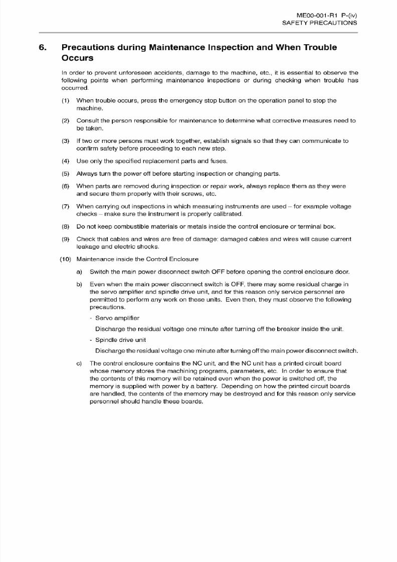
6. Precautions during Maintenance
Inspection
and When Trouble
Occurs
In
order to
prevent
unforeseen
accidents, damage
to the
machine, etc., it
is essential to
observe the
following points
when
performing
maintenance
inspections
or
during
checking when
trouble
has
occurred.
(1)
When
trouble
occurs, press the emergency
stop
button on
the
operation panel to
stop
the
machine.
(2)
Consult the person
responsible for maintenance to
determine
what corrective measures
need
to
be taken.
(3) If two or
more
persons
must work together,
establish
signals
so
that
they
can communicate to
confirm
safety
before
proceeding
to
each
new
step.
(4)
Use
only
the
specified replacement
parts
an d
fuses.
(5)
Always
turn
the
power off
before
starting
inspection
or
changing
parts.
(6)
When
parts
are removed
during
inspection or repair
work, always
replace
them as
they
were
and
secure
them
properly with
their
screws,
etc.
(7)
When
carrying
out
inspections
in
which
measuring
instruments
are used
for
example
voltage
checks
make
sure
the
instrument
is
properly
calibrated.
(8)
Do
not
keep
combustible
materials or metals
inside the
control enclosure
or
terminal
box.
(9)
Check
that
cables and
wires
are
free
of
damage:
damaged cables and
wires
will
cause
current
leakage
and electric
shocks.
(10)
Maintenance inside the Control Enclosure
a)
Switch
the
main
power
disconnect
switch
OFF before
opening
the control enclosure
door.
b)
Even when the main
power
disconnect switch is
OFF,
there
may
some residual
charge in
the
servo
amplifier
and
spindle
drive
unit,
and for this reason
only
service
personnel
are
permitted
to
perform
any
work
on these
units. Even then,
they must observe the following
precautions.
-
Servo
amplifier
Discharge the residual voltage
one minute after
turning
off
the
breaker inside the unit.
-
Spindle
drive
unit
Discharge
the residual
voltage
one minute after
turning
off the main
power
disconnect switch.
c)
The control enclosure contains the NC
unit,
and the NC
unit
ha s
a
printed
circuit board
whose memory
stores the
machining programs,
parameters,
etc.
In
order to
ensure
that
the
contents of this
memory
will
be
retained
even when the
power
is switched
off,
the
memory
is
supplied
with
power
by
a
battery.
Depending
on
how
the
printed circuit
boards
are
handled,
the
contents of
the
memory
may
be destroyed and for this
reason
only
service
personnel
should handle
these
boards.
8/15/2019 Okuma Manuals 391
http://slidepdf.com/reader/full/okuma-manuals-391 6/397
ME00-001-R1
P-(v)
SAFETY
PRECAUTIONS
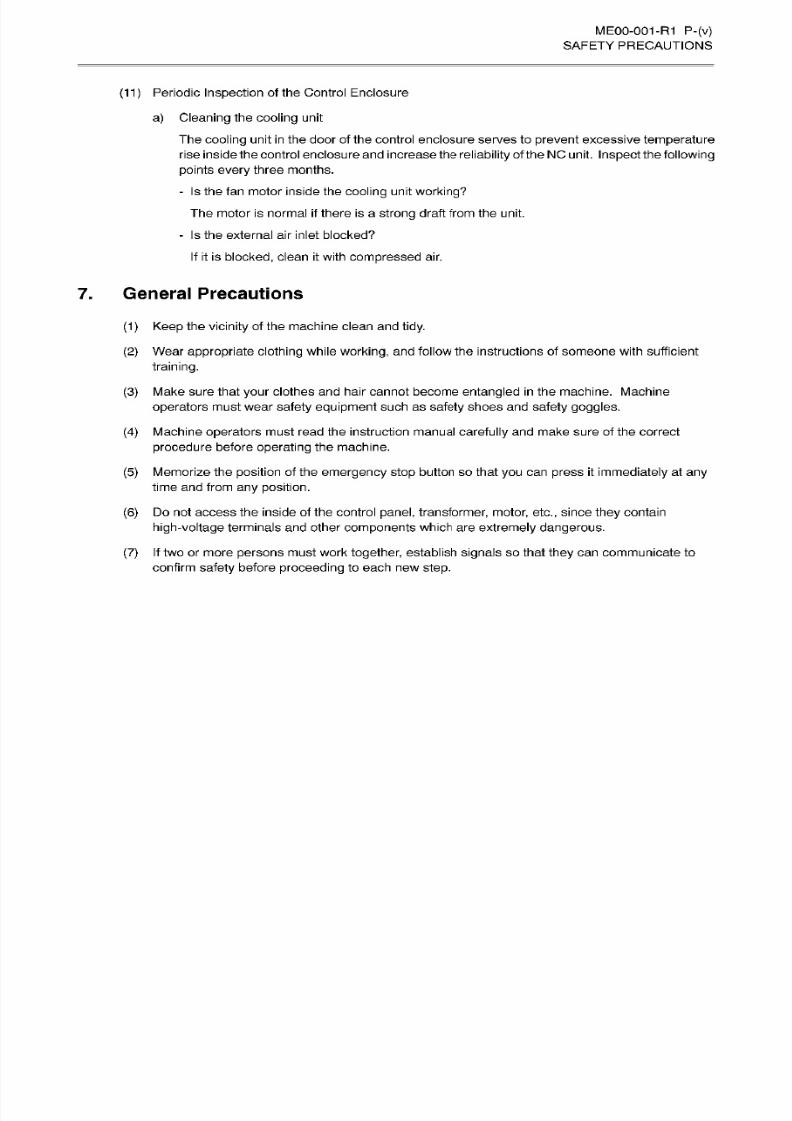
(11) Periodic Inspection of the Control Enclosure
a) Cleaning the
cooling
unit
The
cooling
unit
in
the
door
of the control enclosure serves to prevent excessive temperature
rise inside
the control enclosure
and
increase the
reliability
of theNCunit.
Inspect
the
following
points every
three
months.
-
Is the
fan motor
inside the
cooling
unit working?
The
motor is
normal
if
there
is
a
strong draft from the unit.
-
Is
the external
air
inlet
blocked?
If
it is
blocked,
clean it with
compressed
air.
7.
General Precautions
(1)
Keep
the
vicinity
of the machine
clean and
tidy.
(2)
Wear
appropriate
clothing
while
working,
and
follow
the
instructions
of
someone with sufficient
training.
(3) Make
sure that
your clothes
and hai r
cannot
become
entangled in
the
machine. Machine
operators
must
wear
safety
equipment
such as
safety
shoes and safety
goggles.
(4) Machine
operators
must
read
the
instruction manual
carefully
an d make sure
of
the
correct
procedure
before operating
the machine.
(5)
Memorize the
position
of
the
emergency
stop
button
so that
you
can
press
it immediately
at
any
time
and from
an y
position.
(6)
Do
not
access
the inside
of
the control
panel,
transformer, motor,
etc.,
since
they
contain
high-voltage
terminals and
other
components which are
extremely dangerous.
(7) If two
or more
persons must work together, establish
signals
so
that they can communicate
to
confirm
safety
before
proceeding to
each
new
step.

8/15/2019 Okuma Manuals 391
http://slidepdf.com/reader/full/okuma-manuals-391 7/397
ME00-001-R1
P-(vi)
SAFETY PRECAUTIONS
8. Symbols Used in This
Manual
The
following
warning
indications are
used in
this manual to draw attention to information of
particular
importance.
Read the
instructions
marked
with these
symbols
carefully
and
follow them.
ADANGER
:
Indicates
an
imminent
hazard
which,
if
not
avoided,
will
result
in
death
or
serious
injury.
|AMiG|
|
:
Indicates hazards
which, if
not
avoided,
could result in
death
or
serious
injury.
ACAUTION
:
lnclicates
hazards which,
if
not
avoided,
could
result
in
minor
injuries
or
damage
to
devices
'
or
equipment.
NOTICE
:
Indicates precautions
relating
to
operation
or use.

8/15/2019 Okuma Manuals 391
http://slidepdf.com/reader/full/okuma-manuals-391 8/397
4202-E
P-(i)
INTRODUCTION
INTRODUCTION
This
special
function
manual
contains instructions for
the
OSR
A
careful
reading
of the manual will be of
great
assistance
in obtaining
the full benefit
of al l
the
superior
functions the machine ha s to offer. For the
most
complete
understanding,
this manual should be
read in
conjunction with
the
“Operation Manual
for
OSP”, as
the two
manuals
are
very
closely
related.
8/15/2019 Okuma Manuals 391
http://slidepdf.com/reader/full/okuma-manuals-391 9/397
A.
ANIMATION FUNCTION
TOOL
PATH
DISPLAY FUNCTION
.
C.
NC OPERATION
MONITOR
Hi2-NC
FUNCTION
(HIGH-SPEED
NC).
E.
SYNCHRONIZED
TAPPING
FUNCTION
TOOL MANAGEMENT
FUNCTION.
G. TOOL
LIFE
MANAGEMENT
FUNCTION
PPC
(PALLETE
POOL
LINE
CONTROL)
FOR
HORIZONTAL
MC MULTI-PLANE
APC
(FOR
MX
SERIES)
H.
PPC
(PALLETE
POOL
LINE
CONTROL)
FOR
HORIZONTAL
MC MULTI-STATION
APC
(FOR
MC
SERIES)
I
SPINDLE
THERMAL
DEVIATION
COMPENSATION
SYSTEM
v2
(FOR
STANDARD
AND
ATTACHMENT
MOUNTABLE SPINDLES)
J.
READ/WRITE
AND
GET/PUT
FUNCTIONS
(WITH FILE
INPUT/OUTPUT
FUNCTION)
K.
L.
Hi-CUT
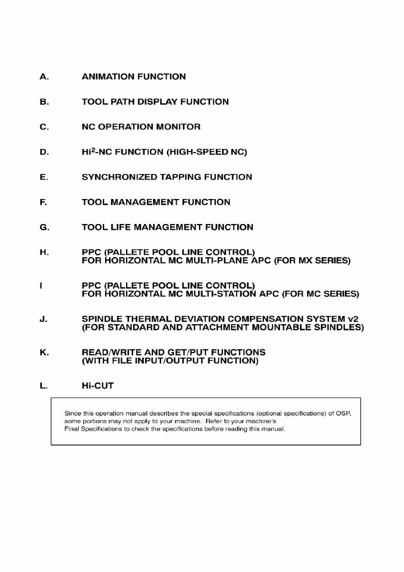
Since this operation manual describes the special specifications
(optional specifications) of
OSP,
some
portions
may
not
apply
to
your
machine. Refer to
your
machine’s
Final
Specifications
to
check the
specifications
before
reading
this
manual.

8/15/2019 Okuma Manuals 391
http://slidepdf.com/reader/full/okuma-manuals-391 10/397
4202-E
P-(i)
TABLE OF
CONTENTS
TABLE
OF CONTENTS
PAGE
A.
ANIMATION FUNCTION
SECTION 1
GENERAL A-1
Special
Features
A-1
.
2. Main Functions
A-1
3.
Screen
Layout
4.
Animation
Screen,
Explanation
of
Terminology
A-5
A-6
SECTION
2
TYPES OF ANIMATION
A-12
1
.
Graphic
Display
Coordinate
System
2.
Explanation
of
Animation Related Functions . .
2-1.
Trace/Animation
2-2.
Tool Kind
2-3.
Material
2-4.
Graphic Erase
2-5. Data
ON/OFF
2-6. High Draw
Graphic
Data
2-8.
Auto Scale
2-9. Area
Change
2-10.
Angle Change
2-11.
Blank
Definition
Function (Blank Define) .
2-12.
Tool Shape Setting
3.
Explanation
of
Animation Related NC
Program
4.
Rotary
Axis, Parallel Axis, 5-Face
Cutting
A-12
A-1
6
A-18
A-20
A-22
A-22
A-23
A-23
A-23
-7.
A-40
A-41
A-44
A-46
A-78
A-82
A-91
SECTION
3 ANIMATION DISPLAY METHOD A-94

8/15/2019 Okuma Manuals 391
http://slidepdf.com/reader/full/okuma-manuals-391 11/397
4202-E
P-(ii)
TABLE OF
CONTENTS
PAGE
B. TOOL PATH DISPLAY FUNCTION
SECTION
1
OVERVIEW
B-1
1.
Features
B-1
2.
Major
Functions B-1
SECTION
2
SETTING OF
DISPLAY
DATA
B-3
1
.
Data
Setting in
the
Graphic
Data
Mode
2. Graphic Data Setting Parameters
3. Data Setting in the
Plane Chance
Mode
B-3
B-4
B-1
2
SECTION 3 TOOL PATH DRAWING B-14
1.
Operations
2. Contents
of
Display
3.
Restart
and
Sequence
Restart
Operations
B-14
B-1
4
B-1
5
SECTION
4
PARAMETERS
B-1
7
C.
NC
OPERATION
MONITOR
SECTION 1 OVERVIEW
C-1
SECTION
2 NC
HOUR
METER C-2
1
.
Contents
of
Display
C-2
2.
Count
Data
and
Set
Data
C-3
3. Alarm
C-3

8/15/2019 Okuma Manuals 391
http://slidepdf.com/reader/full/okuma-manuals-391 12/397
4202-E
P-(iii)
TABLE OF
CONTENTS
PAGE
SECTION 3
NC
WORK COUNTER C-4
1.
Content
of
Display
C-4
2. Count
Data
and
Set
Data C-4
3.
Alarm
C-5
D.
Hi2-NC
FUNCTION (HIGH-SPEED
NC)
SECTION
1
OVERVIEW
D-1
SECTION
2 HIGH-SPEED NC
INTERPOLATION
FUNCTION D-2
SECTION
3 TOLERANCE
CONTROL
FUNCTION D-3
1. Designating
Tolerance Control
Mode
D-3
2.
Tolerance
Control Parameters
D-4
3.
Tolerance
Control Mode
Designation D-7
4.
Tolerance
Control Guide
D-1
3
5.
Alarm
D-1
5
E.
SYNCHRONIZED TAPPING FUNCTION
SECTION 1 OVERVIEW
E-1
SECTION
2
COMMANDS
E-2
SECTION 3 TAPPING CYCLE OPERATIONS
E-5
SECTION
4
PRECAUTIONS
E-7
8/15/2019 Okuma Manuals 391
http://slidepdf.com/reader/full/okuma-manuals-391 13/397
4202-E
P-(iv)
TABLE OF
CONTENTS
PAGE
SECTION 5
TORQUE
MONITORING
FUNCTION
DURING SYNCHRONIZED TAPPING
E-8
SECTION
6 PARAMETERS E-13
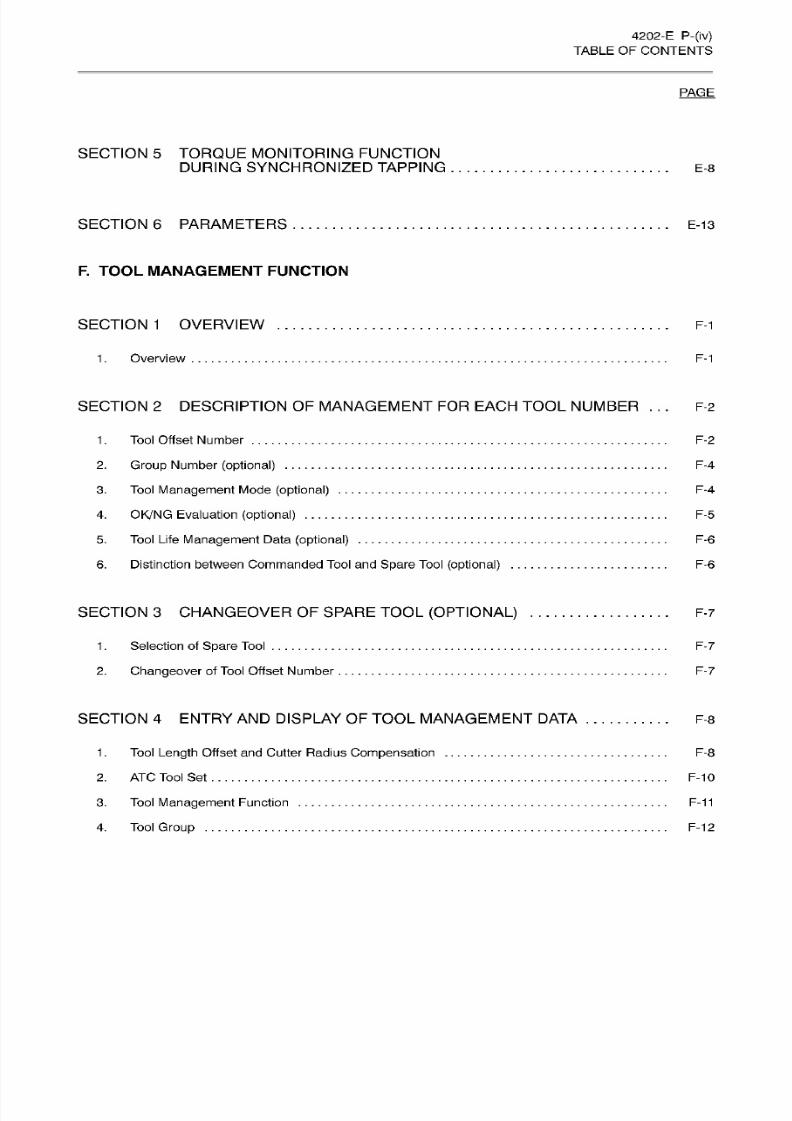
F.
TOOL MANAGEMENT
FUNCTION
SECTION 1 OVERVIEW F-1
1
.
Overview
F-1
SECTION
2
DESCRIPTION OF MANAGEMENT
FOR
EACH TOOL
NUMBER ...
F-2
1
. Tool Offset
Number
F-2
2.
Group
Number
(optional) F-4
3. Tool
Management
Mode
(optional)
F-4
4.
OK/NG
Evaluation
(optional)
5.
Tool
Life
Management
Data
(optional)
6.
Distinction between Commanded Tool and Spare
Tool
(optional)
F-5
F-6
F-6
SECTION 3
CHANGEOVER
OF
SPARE TOOL
(OPTIONAL) F-7
1
.
Selection of
Spare
Tool
2.
Changeover
of
Tool Offset
Number
F-7
F-7
SECTION
4
E NTRY A ND
DISPLAY OF TOOL
MANAGEMENT
DATA
F-8
Tool
Length
Offset
and
Cutter
Radius
Compensation F-8
.
2. ATC
Tool
Set F-10
3.
Tool
Management
Function F-1
1
4.
Tool
Group
F-1
2
8/15/2019 Okuma Manuals 391
http://slidepdf.com/reader/full/okuma-manuals-391 14/397
4202-E
P-(v)
TABLE OF
CONTENTS
PAGE
SECTION 5 RESETTING DEFECTIVE TOOL
DATA
F-13
SECTION
6
MANAGEMENT OF
TOOLS FOR WHICH ATC IS NOT USED F-14
1
.
Command Format
F-14
2.
Tool
Data
Setting
3. Supplements
F-15
F-15
SECTION
7
ALARM
LIST
F-16
G. TOOL
LIFE
MANAGEMENT FUNCTION
SECTION
1
OVERVIEW
G-1
SECTION
2 ENTRY
OF TOOL
LIFE
MANAGEMENT
DATA G-2
1
.
Setting
Tool No.
for
Pot No
1 -1
. Setting Tool No. for P ot N o
2.
Setting
Tool
Life
Management
Data
Setting
Tool
Group
2-2.
Setting Management
Mode
2-3.
Setting SE T TIME
and
LEFT
TIME
Data
G-4
G-4
G-6
G-6
-1.
G-8
G-10
SECTION
3
COMMAND FOR ACTIVATING TOOL LIFE MANAGEMENT
G-1
2
SECTION
4
RESETTING
TOOL
LIFE DATA
G-1
4
1
.
Fo r Usable Tools G-1
4
2. Changing
a Life-expired Tool
with
New
One G-15
3.
Setting
LEFT
TIME Data
to
the
Same
Value
as SET
TIME
Data for
All
Tools G-1
5
8/15/2019 Okuma Manuals 391
http://slidepdf.com/reader/full/okuma-manuals-391 15/397
4202-E
P-(vi)
TABLE OF
CONTENTS
PAGE
SECTION 5 PROGRAM EXAMPLES G-16
1.
Tool
Life
Management by
Tool Used
Time
Data
2.
Tool
Life
Management
by
Count
Data
of
Machining
Cycles
G-16
G-17
SECTION
6
ALARM
LIST G-18
H.
PPC
(PALLETE
POOL
LINE
CONTROL)
FOR
HORIZONTAL MC
MULTI-PLANE
APC
SECTION
1
PREFACE
H-1
SECTION
2
PPC
CYCLE
OPERATION
PROCEDURES H-3
SECTION
3
CREATING
THE
MACHINING PROGRAM
FO R
PPC
CYCLE OPERATION
H-4
1
.
Creating
the
Pallet Exchange Machining Program
2. Creating
the PPC
Cycle
Operation
Machining Program
H-4
H-4
SECTION
4
PPC
PANEL OPERATION
H-5
1
.
Touch
Panel
H-6
Status
transition
using
the MENU and PAGE
Keys
on
the
Touch Panel
Pallet
Carry-in
Screen
Pallet Carry-out Screen
Machining
Schedule
Display
Screen
Manual
Operation
Screen
H-6
-1.
H-8-2.
H-10-3.
H-1
2-4.
1-5.
H-1
4
2.
PPC
Mode Switch
H-17
3.
Schedule
Switch
H-17
Automatic Schedule-1.
H-17
3-2.
Waiting
Schedule
3-3.
Interrupt
Schedule
3-4.
WAITING SCHEDULE STOP Switch
H-17
H-17
H-1
8
8/15/2019 Okuma Manuals 391
http://slidepdf.com/reader/full/okuma-manuals-391 16/397
4202-E
P-(vii)
TABLE OF
CONTENTS
PAGE
4.
EMPTY
PALLET Carry-in Switch H-18
5.
IN
Switch
H-18
6. OUT
Switch
H-18
7. PPC
CYCLE
START
Switch/CYCLE
START Switch
7-1
.
PPC
CYCLE
START
Switch
on
the PPC Panel and the CYCLE
START Switch
on
the Machine
Operation
Panel in the PPC ON
(CONT,
ONE
CYCLE
7-2.
PPC CYCLE
START Switch
on
the
PP C
Panel and
the CYCLE
START Switch
on the Machine
Operation
Panel
in
the PP C OFF State
H-19
H-19
H-20
8.
EMG. STOP Switch
H-20
9. RESTART Switch H-20
SECTION 5 CARRYING
IN
PALLETS
H-21
1
. Carry-in by
the Automatic and
Waiting Schedules
2.
Carry-in
by
the
Interrupt
Schedule
2-1. Machining
Schedule
in the
Interrupt Schedule Mode
on
PP C Panel
3.
Carring in
the
Empty
Pallet
4. Carry-in While
the
PPC
is
Off
H-22
H-24
H-26
H-28
H-30
SECTION
6 CARRYING OUT PALLETS H-32
1.
Carry-out while the
PPC is
On
or Off
2. Automatic
Carrying-out
of
Processed
Pallet when
Only
Tw o
Pallets Are
Used
H-33
H-35
SECTION
7
ASSIGNING PPC CYCLE
OPERATION
MACHINING PROGRAMS
TO
PALLET NUMBERS
H-36
1.
Assigning Procedures H-36
SECTION
8
EDTING
MACHINING
SCHEDULE
H-39
SECTION
9 MACHINING PROGRAM
AND
SYSTEM VARIABLES H-43
1. VPLDT
[1] to
VPLDT [1
2J/VPPCP
H-43
2.
VPLNO H-46
8/15/2019 Okuma Manuals 391
http://slidepdf.com/reader/full/okuma-manuals-391 17/397
4202-E
P-(viii)
TABLE OF
CONTENTS
PAGE
SECTION 10 SETTING SYSTEM MAINTENANCE PARAMETERS
H-47
1. Setting
Data on
the
SETUP.WAITING
ST/MAC.CIR
PNO.
SE T
Screen
H-47
2.
Setting Data on the
[Pallet
Station
No.-Pallet
No.
Table
Screen]
3.
Communication Interface between the Touch Panel
and
NC
(RS232C
Communication
Parameters)
H-48
H-49
SECTION
11
CHECKING
THE PPC
SYSTEM CONDITION
H-50
SECTION 12
NP
COMMAND H-51
SECTION 13
ERRORS
DISPLAYED
ON
THE
PPC
PANEL
H-52
1.
Error at
Carry-in
Operation
. .
2.
Errors
at
Carry-out
Operation
H-52
H-52
3.
Other Errors
H-53
SECTION
14
GENERATED ALARMS H-54
I.
PP C
(PALLETE POOL
LINE
CONTROL) FOR HORIZONTAL MC
MULTI-STATION
APC
SECTION
1
PREFACE
1-1
SECTION
2
PPC CYCLE
OPERATION
PROCEDURES I-3
SECTION
3 CREATING
THE MACHINING PROGRAM
FO R
PPC
CYCLE
OPERATION
I-4
1
.
Creating
the
Pallet
Exchange Machining Program
2. Creating the
PPC
Cycle Operation
Machining Program
I-4
I-4

8/15/2019 Okuma Manuals 391
http://slidepdf.com/reader/full/okuma-manuals-391 18/397
4202-E
P-(ix)
TABLE OF
CONTENTS
PAGE
SECTION
4
PPC
PANEL
OPERATION 1-5
1.
Touch
Panel
I
-6
Status
transition
using
the
MENU and PAGE
Keys
on the
Touch
Panel
Pallet Carry-in
Screen
Pallet
Carry-out Screen
Machining
Schedule
Display
Screen
Manual
Operation
Screen
I
-6
-1.
I-7-2.
I-9
-3.
1-11
-4.
1-5.
1-13
2. PPC
Mode
Switch
1-15
3.
Schedule Switch
1-15
3-1.
Automatic Schedule
1-15
3-2.
Waiting
Schedule
3-3.
Interrupt
Schedule
3-4.
WAITING
SCHEDULE
STOP
Switch
1-15
1-16
1-16
4.
EMPTY
PALLET
Carry-in
Switch
1-16
5. IN Switch 1-16
6.
OUT Switch
1-16
7.
PPC
CYCLE
START
Switch/CYCLE
START
Switch
7-1
.
PPC
CYCLE START
Switch on the PPC Panel and the CYCLE
START
Switch
on
the Machine
Operation
Panel in
the
PPC
ON
(CONT,
ONE CYCLE
7-2.
PPC CYCLE START
Switch
on
the PP C
Panel and
the CYCLE
START
Switch
on
the
Machine
Operation
Panel
in
the PP C OFF State
1-16
1-17
1-18
8.
EMG. STOP Switch 1-18
9. RESTART Switch 1-18
SECTION
5
CARRYING
IN
PALLETS
1-19
1.
Carry-in
by
the Automatic and
Waiting
Schedules
2.
Carry-in
by
the
Interrupt
Schedule
2-1.
Machining
Schedule
in the
Interrupt
Schedule Mode on PP C Panel
3.
Carring in
the
Empty
Pallet
4.
Carry-in
While the
PPC
is Off
I-20
I-22
I-24
I-26
I-28
8/15/2019 Okuma Manuals 391
http://slidepdf.com/reader/full/okuma-manuals-391 19/397
4202-E
P-(x)
TABLE OF
CONTENTS
PAGE
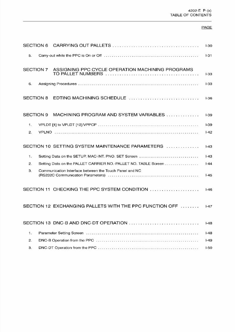
SECTION 6 CARRYING OUT PALLETS 1-30
5.
Carry-out
while
the PPC is
On
or
Off
1-31
SECTION
7
ASSIGNING PPC CYCLE
OPERATION MACHINING
PROGRAMS
TO
PALLET
NUMBERS
I-33
6.
Assigning
Procedures I-33
SECTION 8 EDTING MACHINING SCHEDULE I-36
SECTION 9 MACHINING PROGRAM
AND
SYSTEM VARIABLES I-39
1
. VPLDT
[1]
to
VPLDT
[1
2J/VPPCP
I-39
2. VPLNO I-42
SECTION
10
SETTING SYSTEM
MAINTENANCE
PARAMETERS
I-43
1
. Setting
Data
on
the
SETUP,
MAC-INT. PNO. SET Screen
2. Setting Data on
the
PALLET CARRIER
NO.-PALLET
NO. TABLE Screen
I-43
I-44
3. Communication Interface between the Touch Panel and NC
(RS232C
Communication
Parameters)
I-45
SECTION
11
CHECKING
THE
PPC SYSTEM CONDITION
I-46
SECTION
12
EXCHANGING PALLETS
WITH
THE
PPC
FUNCTION
OFF
I-47
SECTION
13
DNC-B
AND DNC-DT
OPERATION
I-48
1.
Parameter Setting Screen
2.
DNC-B
Operation
from the
PPC .
3.
DNC-DT
Operation
from the
PP C
i-48
I-49
I-50

8/15/2019 Okuma Manuals 391
http://slidepdf.com/reader/full/okuma-manuals-391 20/397
4202-E
P-(xi)
TABLE OF
CONTENTS
PAGE
SECTION
14
ERRORS DISPLAYED ON
THE
PPC
PANEL
1-51
1.
Error
at
Carry-in Operation
. .
2. Errors at
Carry-out
Operation
1-51
1-51
3.
Other
Errors
I-52
4.
AP C Interlock Error
I-53
SECTION
15 GENERATED
ALARMS
I-54
J.
SPINDLE
THERMAL
DEVIATION COMPENSATION SYSTEM
v2
(FOR
STANDARD
AND
ATTACHMENT MOUNTABLE
SPINDLES)
SECTION
1
OUTLINE
J-1
SECTION
2
COMPENSATION
SYSTEM
CONFIGURATION
J-2
SECTION 3 SYSTEM
I
J-3
1
.
Screen for
Checking
Thermal Deviation
Compensation Data
1-1.
A/D
SAMPLING
1-2.
A/DAVE
TIMES
1-3.
TEMPERATURE
1-4.
ESTIMATE
1-5.
COMP.
1-6.
OVERALL
VALUE
1-7. AXIS
(Thermal Deviation)
1/2/3
1-8.
ROTARY DEV.
J-3
J-3
J-3
J-3
J-3
J-3
J-3
J-4
J-4
2. Alarm
Message
3.
Precaution Regarding Thermal Deviation
Compensation
Parameters
3-1. Screen Transition
J-5
J-8
J-8
4.
Thermal Deviation
Comp.
Common Parameter
Screen
1 (Page
1)
4-1.
COMPENSATION SW
(No.1)
J-9
J-10
8/15/2019 Okuma Manuals 391
http://slidepdf.com/reader/full/okuma-manuals-391 21/397
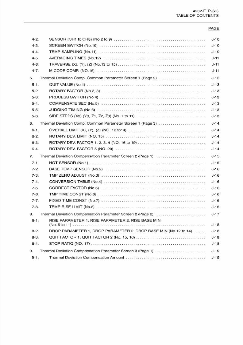
4202-E
P-(xii)
TABLE OF
CONTENTS
PAGE
4-2.
SENSOR
(CH1
to
CH8)
(No.2 to
9)
4-3.
SCREEN SWITCH
(No.10 )
4-4.
TEMP
SAMPLING
(No.11)
4-5. AVERAGING TIMES
(No.12)
4-6.
TRAVERSE
(X),
(Y),
(Z)
(No.
13
to 15)
4-7. M CODE
COMP.
(NO.
16)
5.
Thermal
Deviation
Comp.
Common
Parameter
Screen
1 (Page
2)
5-1.
QUIT
VALUE
(No.1)
5-2.
ROTARY
FACTOR
(No.2,
3)
5-3.
PROCESS SWITCH
(No.4)
5-4. COMPENSATE
SE C (No.5)
5-5. JUDGING TIMING
(No.6)
5-6. SIDE
STEPS
(X3)
(Y3,
Z1
,
Z2 , Z3) (No. 7
to
11)
6.
Thermal
Deviation
Comp.
Common
Parameter
Screen
1 (Page
3)
6-1. OVERALL LIMIT
(X), (Y), (Z)
(NO.
12
to14)
6-2. ROTARY
DEV.
LIMIT (NO.
15)
6-3. ROTARY
DEV.
FACTOR
1, 2, 3, 4
(NO.
1
6 to
1
9)
6-4.
ROTARY
DEV.
FACTOR
5 (NO. 20)
7. Thermal Deviation Compensation Parameter Screen 2
(Page
1)
7-1.
HOT
SENSOR
(No.1)
7-2.
BASE
TEMP
SENSOR
(No.2)
7-3.
TM P ZERO
ADJUST
(No.3)
7-4. CONVERSION
TABLE
(No.4)
7-5. CORRECT
FACTOR
(No.5)
7-6.
TM P TIME
CONST (No.6)
7-7. FIXED TIME
CONST
(No.7)
7-8.
TEMP
RISE
LIMIT (No.8)
8. Thermal Deviation Compensation Parameter Screen
2
(Page
2)
8-1. RISE
PARAMETER 1,
RISE
PARAMETER 2,
RISE BASE
MIN
(No. 9 to
11)
8-2. DROP
PARAMETER 1,
DROP
PARAMETER
2,
DROP
BASE
MIN (No.12
to
14)
8-3.
QUIT FACTOR
1,
QUIT FACTOR
2
(No. 15, 16 )
8-4.
STOP
RATIO
(NO.
17)
9.
Thermal Deviation Compensation Parameter Screen 3
(Page 1)
9-1. Thermal Deviation Compensation Amount
J-10
J-10
J-10
J-11
J-11
J-11
J-12
J-13
J-13
J-13
J-13
J-13
J-13
J-14
J-14
J-14
J-14
J-14
J-15
J-16
J-16
J-16
J-16
J-16
J-16
J-16
J-16
J-17
J-18
J-18
J-18
J-18
J-19
J-19
8/15/2019 Okuma Manuals 391
http://slidepdf.com/reader/full/okuma-manuals-391 22/397
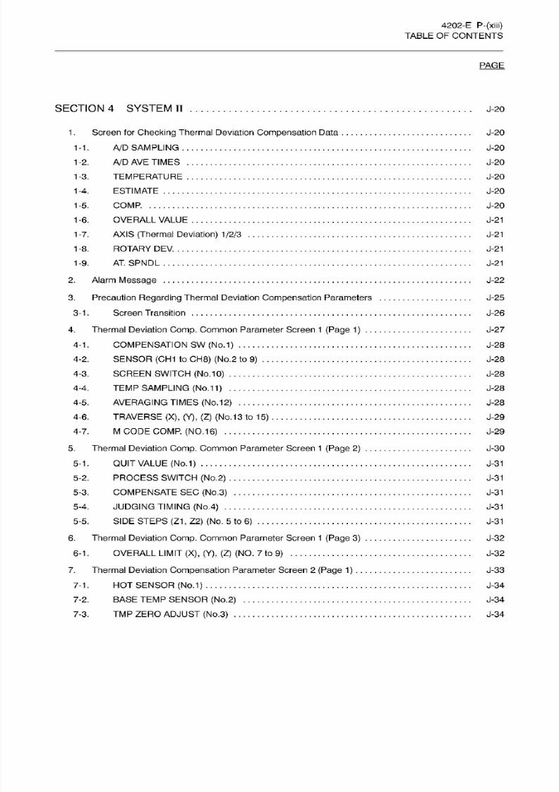
4202-E
P-(xiii)
TABLE OF
CONTENTS
PAGE
SECTION
4
SYSTEM
II
J-20
1.
Screen for
Checking
Thermal Deviation
Compensation
Data
1-1.
A/D
SAMPLING
1-2.
A/DAVE
TIMES
1-3.
TEMPERATURE
1-4.
ESTIMATE
1-5.
COMP.
1-6.
OVERALL
VALUE
1-7.
AXIS
(Thermal Deviation)
1/2/3
1-8.
ROTARY
DEV.
AT.
SPNDL
J-20
J-20
J-20
J-20
J-20
J-20
J-21
J-21
J-21
J-21-9.
2.
Alarm
Message
3.
Precaution
Regarding
Thermal Deviation Compensation Parameters
3-1.
Screen
Transition
J-22
J-25
J-26
4.
Thermal Deviation
Comp.
Common Parameter Screen
1 (Page 1)
4-1.
COMPENSATION
SW (No.1)
4-2. SENSOR
(CH1
to
CH8) (No.2
to
9)
4-3.
SCREEN SWITCH
(No.
10)
4-4.
TEMP
SAMPLING
(No.11)
4-5.
AVERAGING
TIMES
(No.12)
4-6. TRAVERSE
(X),
(Y),
(Z) (No.
13 to
15)
4-7. M
CODE
COMP.
(NO.16 )
5.
Thermal
Deviation
Comp.
Common Parameter Screen
1 (Page
2)
5-1.
QUIT
VALUE
(No.
1)
5-2. PROCESS SWITCH
(No.2)
5-3.
COMPENSATE SEC
(No.3)
5-4.
JUDGING TIMING (No.4)
5-5.
SIDE
STEPS (Z1,
Z2 ) (No.
5 to
6)
6. Thermal Deviation Comp. Common Parameter Screen
1
(Page 3)
6-1.
OVERALL
LIMIT
(X),
(Y),
(Z)
(NO.
7
to
9)
7.
Thermal Deviation Compensation Parameter Screen
2 (Page
1)
. .
7-1.
HOT SENSOR
(No.1)
7-2.
BASE
TEMP
SENSOR
(No.2)
7-3.
TM P
ZERO
ADJUST
(No.3)
J-27
J-28
J-28
J-28
J-28
J-28
J-29
J-29
J-30
J-31
J-31
J-31
J-31
J-31
J-32
J-32
J-33
J-34
J-34
J-34
8/15/2019 Okuma Manuals 391
http://slidepdf.com/reader/full/okuma-manuals-391 23/397
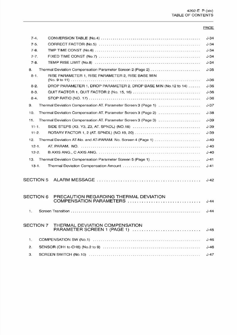
4202-E
P-(xiv)
TABLE OF
CONTENTS
PAGE
7-4.
CONVERSION TABLE
(No.4)
7-5.
CORRECT
FACTOR (No.5)
7-6.
TM P
TIME
CONST
(No.
6)
7-7. FIXED TIME
CONST
(No.7)
7-8.
TEMP
RISE
LIMIT (No.8)
8.
Thermal
Deviation
Compensation
Parameter
Screen 2 (Page 2)
8-1.
RISE
PARAMETER
1,
RISE
PARAMETER 2,
RISE
BASE MIN
(No.
9
to
11)
8-2.
DROP
PARAMETER 1,
DROP
PARAMETER
2,
DROP
BASE MIN
(No.12 to 14)
8-3.
QUIT
FACTOR
1
,
QUIT FACTOR 2
(No.
15,
16)
8-4.
STOP
RATIO
(NO.
17)
J-34
J-34
J-34
J-34
J-34
J-35
J-36
J-36
J-36
J-36
9.
Thermal
Deviation
Compensation
AT.
Parameter Screen
3
(Page
1)
1
0.
Thermal
Deviation
Compensation
AT.
Parameter
Screen 3
(Page
2)
J-37
J-38
11 .
Thermal Deviation
Compensation
AT.
Parameter Screen
3
(Page 3)
11-1.
SIDE STEPS (X3,
Y3 ,
Z3 , AT.
SPNDL)
(NO.18)
11-2. ROTARY
FACTOR
1, 2 (AT. SPNDL) (NO.19, 20)
12.
Thermal
Deviation AT-No.
and AT-PARAM.
No .
Screen
4
(Page
1) .
12-1.
AT.PARAM.NO
12-2. B
AXIS
ANG.,
C AXIS ANG
1
3.
Thermal Deviation
Compensation
Parameter
Screen
5
(Page
1
) . . .
13-1
. Thermal Deviation
Compensation Amount
J-39
J-39
J-39
J-40
J-40
J-40
J-41
J-41
SECTION
5
ALARM
MESSAGE
J-42
SECTION
6
PRECAUTION REGARDING
THERMAL
DEVIATION
COMPENSATION PARAMETERS J-44
1.
Screen Transition J-44
SECTION
7 THERMAL
DEVIATION COMPENSATION
PARAMETER
SCREEN
1
(PAGE 1)
J-45
1. COMPENSATION
SW (No.
1)
....
2.
SENSOR
(CH1
to
CH8) (No.2
to
9)
3.
SCREEN
SWITCH
(No.
10)
J-46
J-46
J-47
8/15/2019 Okuma Manuals 391
http://slidepdf.com/reader/full/okuma-manuals-391 24/397
4202-E
P-(xv)
TABLE OF
CONTENTS
PAGE
4. TEMP SAMPLING
(No.11)
5. AVERAGING TIMES
(No.
12)
6. TRAVERSE (X), (Y),
(Z)
(No.
13
to 15)
J-47
J-47
J-47
SECTION 8 THERMAL DEVIATION
COMPENSATION
PARAMETER
SCREEN
1 (PAGE 2)
J-48
1.
QUIT VALUE
(No.1)
2.
ROTARY
FACTOR
(No.2,
3)
3.
PROCESS SWITCH (No.4)
4.
COMPENSATE
SE C
(No.
5)
5. JUDGING TIMING
(No.6)
6.
SIDE STEPS
(X) (Y, Z1
,
Z2 , Z 3) (No.
7
to
11
)
J-49
J-49
J-49
J-49
J-49
J-49
SECTION
9
THERMAL
DEVIATION COMPENSATION
PARAMETER
SCREEN
1 (PAGE 2)
J-50
1.
HOT
SENSOR
(No.1
2)
2.
BASE
TEMP
SENSOR
(No.13)
3.
TM P
ZERO
ADJUST
(No.1
4)
. .
4. CONVERSION TABLE
(No.
15 )
5.
CORRECT
FACTOR
(No.16 ) . .
6. TM P TIME
CONST
(No.17) .. .
7. FIXED TIME
CONST
(No.
18)
.
8.
TEMP
RISE
LIMIT
(No.1
9)
....
J-51
J-51
J-51
J-51
J-51
J-51
J-51
J-51
SECTION
10 THERMAL
DEVIATION COMPENSATION
PARAMETER
SCREEN
2
(PAGE 2)
J-52
1.
RISE
PARAMETER 1,
RISE
PARAMETER
2, RISE BASE
MIN
(No.
20
to
22 )
J-53
2.
DROP
PARAMETER 1
,
DROP
PARAMETER
2,
DROP
BASE
MIN (No.23
to
25 )
3.
QUIT
FACTOR
1, QUIT
FACTOR
2
(No.
26,
27)
J-53
J-53
8/15/2019 Okuma Manuals 391
http://slidepdf.com/reader/full/okuma-manuals-391 25/397
4202-E
P-(xvi)
TABLE OF
CONTENTS
PAGE
SECTION
11 THERMAL
DEVIATION COMPENSATION
PARAMETER
SCREEN
3
(PAGE
1)
J-54
Thermal Deviation
Compensation Amount
J-54
.
K.
READ/WRITE
AND
GET/PUT
FUNCTIONS
(WITH FILE
INPUT/OUTPUT
FUNCTION)
SECTION 1
GENERAL
K-1
SECTION
2
CONFIGURATION K-2
1. Configuration 1
2.
Configuration 2
K-2
K-2
SECTION 3 FUNCTION
I
K-3
1. READ
Function K-3
2.
WRITE
Function
K-3
3. GET
Function K-4
4. PUT
Function
K-5
SECTION
4
FUNCTION
II(FILE
INPUT/OUTPUT
FUNCTION)
K-7
1.
FOPENA
(FOPENB)
Function
K-7
2.
FWRITC
Function
K-7
3.
READ
Function
K-8
4. WRITE
Function K-8
5.
GET Function
K-9
6. PUT
Function K-9
7.
CLOSE Function K-9
8.
Supplements
K-9
8/15/2019 Okuma Manuals 391
http://slidepdf.com/reader/full/okuma-manuals-391 26/397
4202-E
P-(xvii)
TABLE OF
CONTENTS
PAGE
SECTION 5
EXAMPLE
PROGRAMI K-10
1.
Data
Input
Using READ
and
GET Commands
.
.
2.
Data
Output
Using
PUT
and
WRITE
Commands
K-10
K-11
SECTION
6
EXAMPLE
PROGRAM
II
(FILE
INPUT/OUTPUT
FUNCTION)
K-12
1.
Data Input
by
FOPNEA(B),
READ,
and GET Commands
2. Data
Output
by FWRITC,
PUT,
and WRITE
Commands
.
K-12
K-13
SECTION
7
PARAMETERS
K-14
1
.
NC
Optional
Parameter
(Word)
2. NC
Optional
Parameter (Bit)
.
K-14
K-15
SECTION
8
ALARM K-17
SECTION 9
APPENDIX
K-20
L.
Hi-CUT
SECTION
1
OVERVIEW OF Hi-CUT
L-1
SECTION
2
Hi-CUT CONTROL FUNCTION
L-2
Designating
Hi-Cut
Control Mode
L-2
.
2. Hi
-Cut
Control
Parameters
L-2
3.
Hi-Cut
Control
Mode
Designation
L-4
4.
Hi-Cut Control
Guide L-6

8/15/2019 Okuma Manuals 391
http://slidepdf.com/reader/full/okuma-manuals-391 27/397
A. ANIMATION
FUNCTION
8/15/2019 Okuma Manuals 391
http://slidepdf.com/reader/full/okuma-manuals-391 28/397
4202-E
A-1
A. ANIMATION FUNCTION
SECTION
1
GENERAL
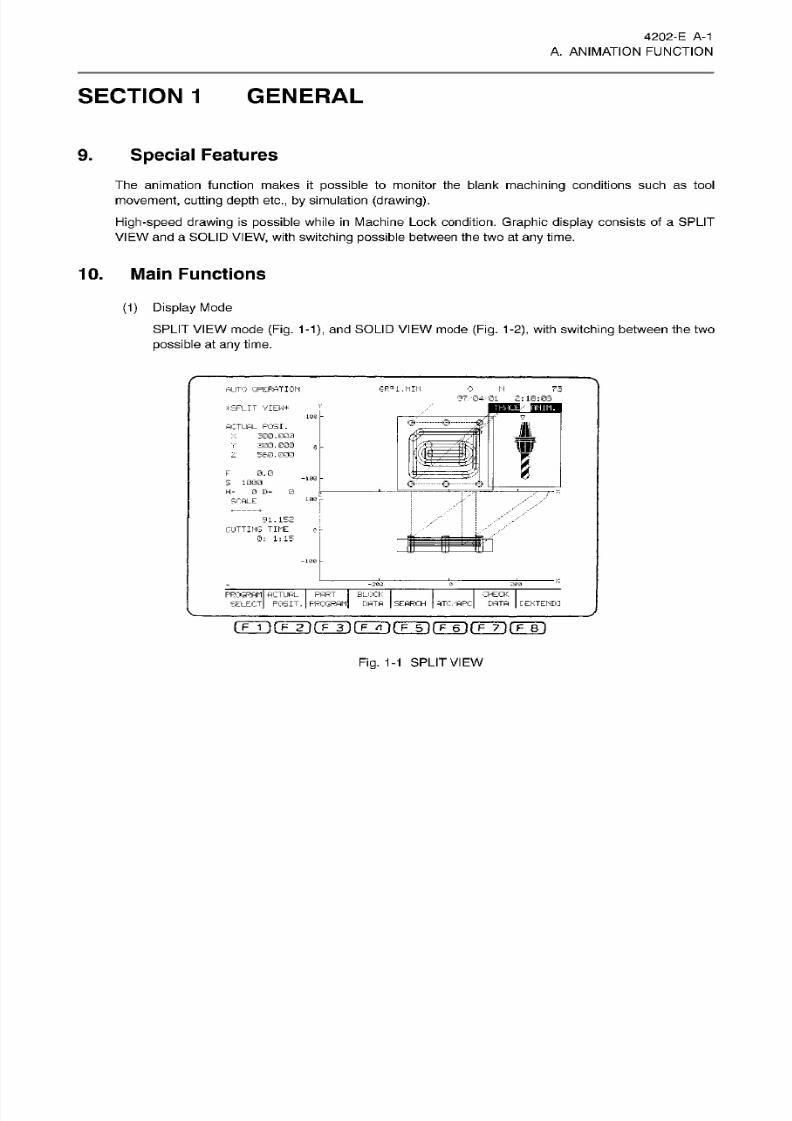
9.
Special
Features
The animation func tion makes it
possible
to monitor the blank
machining
conditions such
as tool
movement, cutt ing depth etc.,
by simulation
(drawing).
High-speed drawing
is
possible
while
in
Machine
Lock condition.
Graphic display
consists
of a SPLIT
VIEW
and
a SOLID VIEW, with
switching possible
between
the
two
at
any
time.
10. Main Functions
(1) Display Mode
SPLIT
VIEW
mode
(Fig. 1-1),
and
SOLID
VIEW
mode
(Fig.
1-2),
with
switching
between the two
possible
at
any
time.
HUTO OPERATION GR°1
.MIN
0
N
73
97,'04,'0i
2:
18:08
tilliH
t
SPLIT
VIEW*
106
a-
$
ACTUAL
P05I.
300.000
300.000
560.000
~T?
e
z
I
0.0
-100
5
1000
H= 0 D=
0
SCALE
91.152
CUTTING
TINE
0: 1:15
0
-203
&
PROGRAM ACTUAL
PART
I
SELECT POSIT. PROGRAM]
BLOCK
DATA SEARCH
ATC/APC
CHECK
DATA
[EXTENDI
Fig.
1-1
SPLIT
VIEW
8/15/2019 Okuma Manuals 391
http://slidepdf.com/reader/full/okuma-manuals-391 29/397
4202-E
A-2
A.
ANIMATION
FUNCTION
AUTO
OPERATION
GRPi .MIN
0
N
73
97/04/01
2 r
18:34
ESSs
_SQ3i9
V
*SOLID
VIEW*
ACTUAL
POSI.
X
3G0.000
V 300.000
2
560.000
JL
o
,
B
0.0
S 1000
H=
0
D=
0
SCALE
69. 120
CUTTING TIME
0:
1:15
z
PROGRAM
ACTUAL
PART BLOCK
T
SELECT
POSIT,
PROGRAM
DATA
SEARCH
ATC/APC
CHECK
E'ATA
[
EXTEND]
I
F
1
IfTTK
F
3)rF7»4fF~5l(T~6lfF~7ÿrF~Bl
Fig.
1-2
SOLID
VIEW
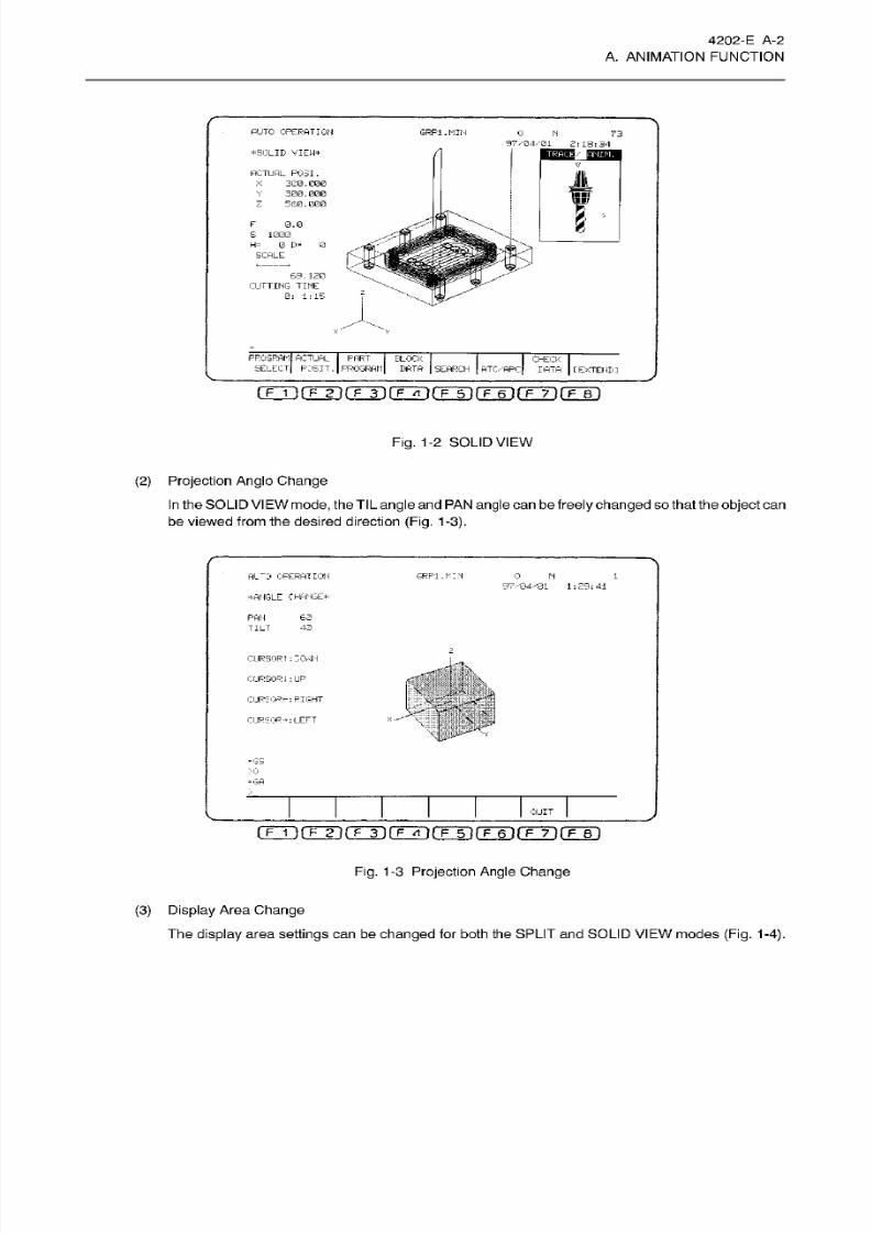
(2)
Projection Anglo Change
In
the SOLI
D
VI
EW mode,
the
TlL angle
and
PA N
angle
can
be
freely
changed
so that the
object can
be viewed from
the
desired direction
(Fig.
1-3).
Al~0
OPERATION
GRPI.
MEN
0
1
97/04/01 1:29:41
WANGLE CHANGE*
PAN
60
TILT
43
z
CURSOR
t
: ECvJH
CURSOR : UP
1
URSOR*-:
RIGHT
|
CURSOR-*:LEFT
S'
=
GS
>Q
—
GA
QUIT
(
F 1
)(7T1I
F
13(ZZ3(Z 13(Z 13CEzI)CElD
Fig.
1
-3
Projection Angle
Change
(3) Display
Area Change
Th e
display
area
settings
can be
changed for
both the SPLIT an d SOLID
VIEW
modes
(Fig. 1-4).
8/15/2019 Okuma Manuals 391
http://slidepdf.com/reader/full/okuma-manuals-391 30/397
4202-E
A-3
A.
ANIMATION
FUNCTION
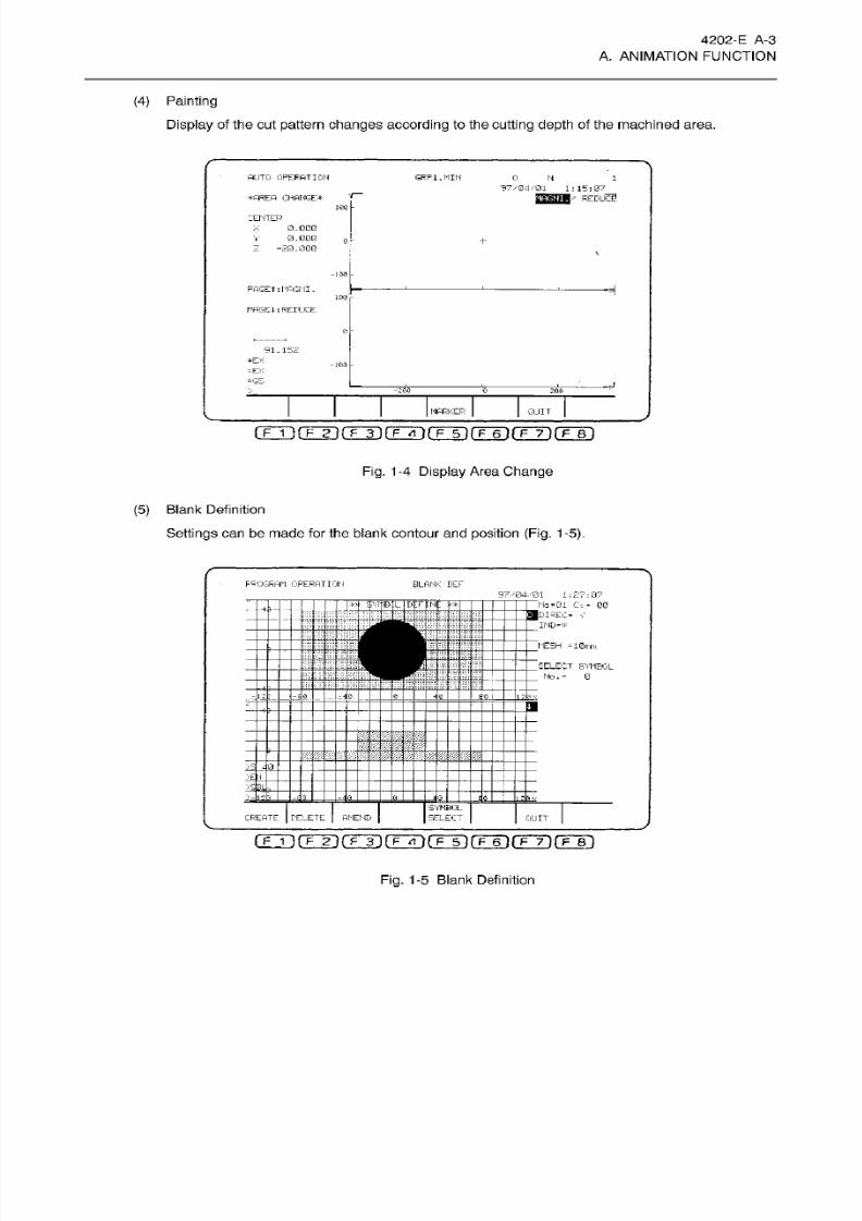
(4) Painting
Display
of the cut
pattern
changes according
to the
cutting
depth
of the machined area.
AUTO
OPERATION
GRFi.MIN 0
N 1
S7V04/Q1
1:15:07
•
REDUCE
AREA CHANGE*
100
CENTER
0.
000
0.000
—
20.
000
+
-
-1-30
H
AGEt
:
MAGNI
.
Im -
PAGEI:REDUCE
0
91
.
152
=EX
-GS
-103
—
T*
-200
0
200
MARKER QUIT
(
F
1
IfTTK
p
3lf F7l'
}rF~5~irÿ60rÿ70fF~Bl
Fig. 1
-4
Display
Area
Change
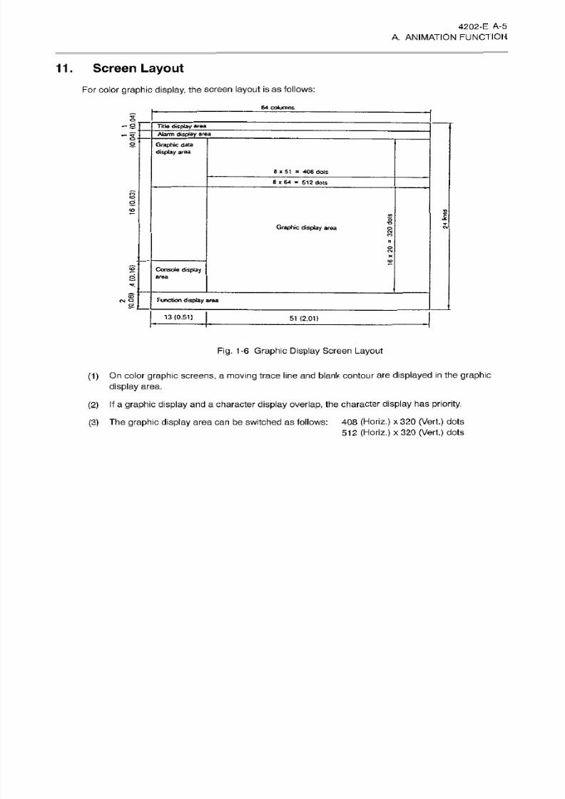
(5)
Blank
Definition
Settings can
be
made
for
the
blank
contour and
position
(Fig.
1-5).
PROGRAM OPERATION
B LA NK B EF
97/04/01.
1:27:07
No =01
Cz
= 0G
-4
1-
ajDIREC- V
IND=*
MESH
=
10mrn
SELECT
SYMBOL
’
No.=
0
go
i
.Am..
0
12b x
a
4-
m
T
il
S T T
pfgl
:
>EN
>-
:
120
M
SYMBOL
SELECT
REATE
DELETE
AMEND
QUIT
fFTirFÿrrT)rFTTirrTirETirrTirF~B~)
Fig. 1-5 Blank Definition

8/15/2019 Okuma Manuals 391
http://slidepdf.com/reader/full/okuma-manuals-391 31/397
4202-E
A-4
A. ANIMATION FUNCTION
(6) Automatic
Setting for
Display
Size
Appropriate
display
size
can
be
automatically
determined
according
to blank size.
(7)
Setting
of
Cutting
Tool Shape
Setting
ca n be made for the
cutting
tool shape.
(8)
Selection
of
Drawing
Speed
Display is possible
for actual
cutting
speed
or
high
speed.
(9) Cutting
Time
Calculation
Cutting
time calculation
function
is available.
(10)
Compatible
for
Rotary
Axis and
Five-face
Machining
Rotary axis,
five-face
machining
is
possible.
(11)
Intervention
for
Return
Operation
Return
search,
sequence
return
operation
intervention is
possible.
8/15/2019 Okuma Manuals 391
http://slidepdf.com/reader/full/okuma-manuals-391 32/397
4202-E
A-5
A.
ANIMATION
FUNCTION
11.
Screen
Layout
For
color
graphic display,
the screen layout
is
as
follows:
64 columns
i
-s'
Title
display
area
Alarm
display area
-I
Graphic
data
display area
S
8
*
51
=
408
dots
8
*
64
=
51 2
dots
§
2
vt
k
5
raphic
display
area
§
M
O
£
S
Console display
area
*r.
4
Function
display
area
S
13(0.51)
51
(2.01)
Fig.
1-6
Graphic
Display
Screen
Layout
(1)
On color
graphic
screens,
a
moving trace
line
and
blank
contour are
displayed in the
graphic
display
area.
(2)
If
a graphic
display and
a
character
display
overlap, the character
display
ha s
priority.
(3)
Th e
graphic display
area
can
be switched as
follows:
408
(Horiz.)
x
320
(Vert.)
dots
512 (Horiz.)
x
320
(Vert.)
dots
8/15/2019 Okuma Manuals 391
http://slidepdf.com/reader/full/okuma-manuals-391 33/397
4202-E A-6-R1
A.
ANIMATION
FUNCTION
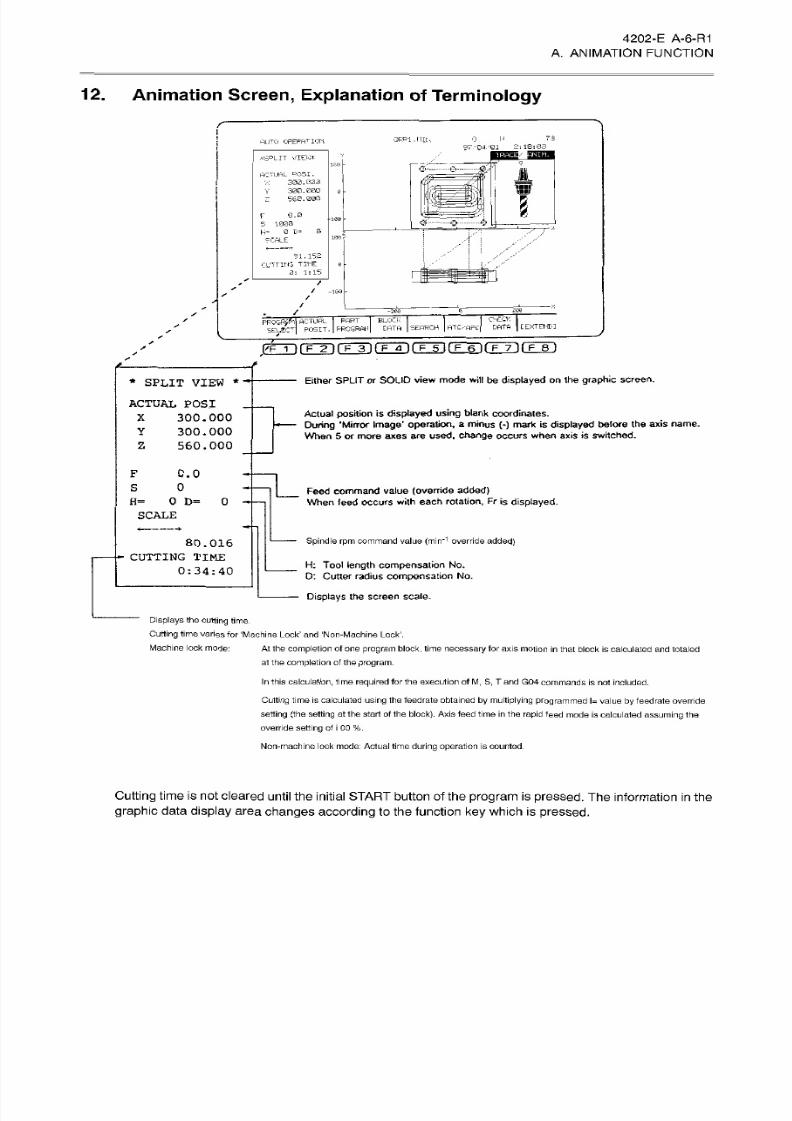
12. Animation
Screen, Explanation
of
Terminology
73
RPl.MIh
AUTO OPERATION
97/04/01
2:18:03
iT3»/
Situm
«S°LIT
VIEW*
&
$ ÿ']
M
1*0
F—
JL
CTUAL
C'05I.
330
.
003
300.000
Z
580.000
1
f
A
0.0
r;<
O
130
* •
1000
H=
0
D=
0
9CALE
100
r
«i.152
CUTTING
TINE
3:
1:15
:
/
s
/
-100
/
/
200
-200
CHECK
DATA
[
EXTENT'
BLOCK
|
DATA
|
SEARCH |
ATO'APC
ROC-fÿpl
ACTUAL
PART
POSIT.
I
PROGRAM
/
FTT1lTÿfFÿlT~73(T~5T(Tÿ(Tÿ(Z8D
Either SPLIT
or
SOLID
view
mode
will
be
displayed on
the
graphic
screen.
*
SPLIT
VIEW
*
ACTUAL
POS.I
300.000
300.000
560.000
Actual
position
is
displayed
using
blank
coordinates.
During
'Mirror Image’
operation,
a minus
(-) mark
is
displayed before
the
axis
name.
When 5 or
more
axes are
used,
change
occurs
when axis
is
switched.
X
Y
Z
0.0
0
_
Feed
command
value
(override
added)
When teed occurs
with
each
rotation,
Fr
is
displayed.
D=
0
=
SCALE
Spindle
rpm
command
value
(min'1
override added)
80.016
CUTTING
TIME
0:34:40
Ft: Tool
length compensation
No.
D:
Cutter radius
compensation
No.
Displays
the screen
scale.
Displays
the
cutting
time.
Cutting
t ime varies for
‘Machine Lock’
and
‘Non-Machine
Lock1.
At
the
completion of
one
program
block,
time
necessary
for
axis
motion in
that block is
calculated and
totaled
a1 the
completion
of the
program.
Machine lock
mode:
In this
calculation,
time
required
for the execution of
M
S,
T
an d G04 commands
is nof
included.
Cutting
time is calculated
using 1he feedrate
obtained by
multiplying programmed
l=
value by
feedrate
override
setting
(the
setting
at
the
start of fhe block).
Axis
feed time in the
rapid
feed
mode is
calculated
assuming
the
override
setting
of
i
00
%.
Non-machine
lock
mode:
Actual
time
during
operation is
counted.
Cutting
time
is
not
cleared until
the
initial START button
of
the
program
is
pressed.
Th e
information
in the
graphic
data display
area
changes
according
to the
function ke y
which
is pressed.
8/15/2019 Okuma Manuals 391
http://slidepdf.com/reader/full/okuma-manuals-391 34/397
4202-E
A-
7
A.
ANIMATION
FUNCTION
PUT0
OPERATION
GRPi.MIN
0 N
1
97/04/01
1:31:
02
1/
RAO
lANIM.IEW#
100
V
ACTUAL F03I.
300.000
3E0.
030
560.030
>:
mr
0
\mwi
2
2
0
.0
*10®
S
0
0 D=
0
=
10®
SCALE
91
.
152
CUTTING
TINE
0: 0: 2
a
-100
-200
0
2®0
CHECK
DPTP
PROGRAM
ACTUAL-
PART
SELECT
POSIT.
PROGRAM
ELOCK
DATA
I
SEARCH
ATC/APC
[EXTEND]
i
F
1
ifFTK
f
3if~FTiTrFinrF~6]fF~7](Tir)
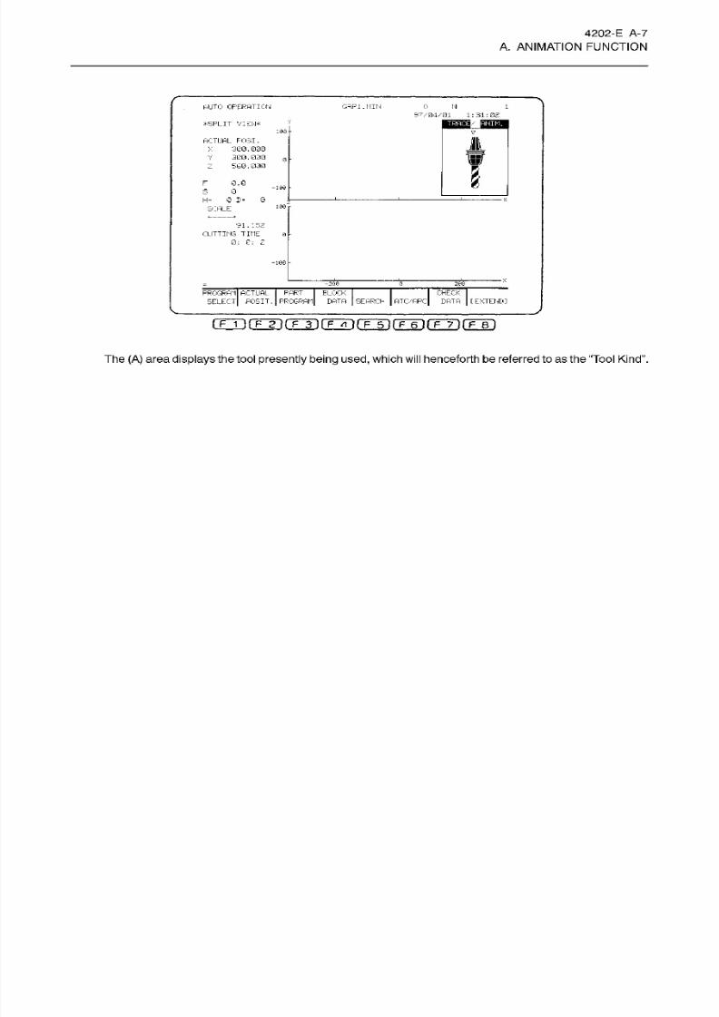
The
(A )
area
displays
the tool
presently being used,
which will henceforth be referred to
as
the “Tool Kind .
8/15/2019 Okuma Manuals 391
http://slidepdf.com/reader/full/okuma-manuals-391 35/397
4202-E A-8
A.
ANIMATION
FUNCTION
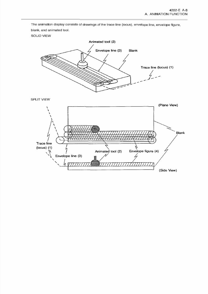
The
animation
display consists of
drawings of the trace
line
(locus), envelope
line,
envelope
figure,
blank,
and
animated
tool.
SOLID VIEW
Animated
tool
(2)
Envelope
line
(3)
Blank
Trace
line
(locus)
(1)
SPLIT
VIEW
(Plane
View)
\
\
\
\
\
\
szzzzzzzzz
/J//
////// / r
\
\
niiiiiiniiiiiiiiiiiiiin
Blank
1
/
m
7
y
VT)
(3
/
/ /
/
Trace
line
(locus)
(1)
\
Animated
tool
(2)
Envelope
figure (4)
\
\
Envelope
line
(3)
\
i
V//////////////////////7
/////////
(Side
View)
8/15/2019 Okuma Manuals 391
http://slidepdf.com/reader/full/okuma-manuals-391 36/397
4202-E
A-9
A. ANIMATION FUNCTION
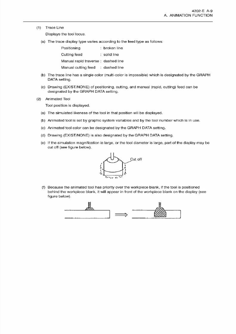
(1 )
Trace Line
Displays
the tool locus.
(a) The trace
display
type
varies
according
to the feed
type
as follows:
Positioning
Cutting feed
Manual
rapid traverse
:
dashed
line
Manual cutting
feed
:
dashed
line
(b) The
trace l ine has a
single
color
(multi-color
is
impossible)
which is
designated by
the GRAPH
DATA
setting.
(c)
Drawing
(EXIST/NONE)
of
positioning, cutting,
an d manual
(rapid,
cutting)
feed can
be
designated by the
GRAPH
DATA setting.
(2 )
Animated
Tool
Tool
position
is
displayed.
(a)
The
simulated
likeness
of
the
tool
in that
position
will
be
displayed.
(b)
Animated tool is
set
by
graphic system
variables
and by the
tool
number which is in
use.
(c)
Animated tool color
can
be
designated by
the
GRAPH
DATA setting.
:
broken line
:
solid
line
(d) Drawing (EXIST/NONE)
is
also
designated
by
the GRAPH
DATA
setting.
(e) If
the simulation
magnification
is
large,
or the tool diameter is
large,
part
of the
display may
be
cut off
(see figure
below).
A
Cut o ff
L
A
(f)
Because
the animated
tool has priori ty
over the
workpiece
blank, if
the
tool
is
positioned
behind
the
workpiece
blank, it
will appear
in
front
of
the
workpiece
blank on the
display (see
figure
below).
8/15/2019 Okuma Manuals 391
http://slidepdf.com/reader/full/okuma-manuals-391 37/397
4202-E
A-
10
A. ANIMATION FUNCTION
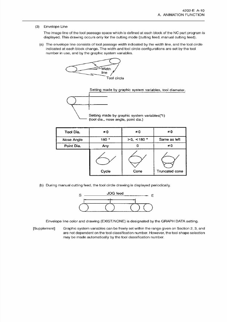
(3) Envelope Line
The
image
line of the tool
passage space
which
is
defined
at
each block of the NO
part program is
displayed.
This
drawing occurs
only
for the
cutting
mode
(cutting feed,
manual
cutting
feed).
(a)
The
envelope
line consists of tool
passage
width indicated
by
the width
line,
and the
tool
circle
indicated
at
each
block
change.
The
width
and
tool circle
configurations are
set
by
the
tool
number
in use,
and
by
the
graphic
system
variables.
Width
line
Tool
circle
Setting
made
by graphic
system
variables,
tool
diameter.
Q
Setting
made by graphic
system
variablesp)
(tool dia.,
nose
angle, point dia.)
*0
ool
Dia. *0
*0
Same as left
ose
Angle 180
e
>0,
<180
•
Point Dia.
Any
0 *0
Cycle Cone
Truncated
cone
(b)
During
manual
cutting feed,
the
tool circle
drawing
is
displayed
periodically.
JO G feed
S
E
C
) ( )
Envelope
l ine color
and
drawing (EXIST/NONE)
is
designated by
the
GRAPH
DATA
setting.
[Supplement]
Graphic system
variables can be
freely
set
within
the
range
given
on
Section
2, 3,
and
are not
dependent
on
the
tool
classification
number.
However, the
tool
shape
selection
may
be m ade
automatically
by
the
tool classification
number.
8/15/2019 Okuma Manuals 391
http://slidepdf.com/reader/full/okuma-manuals-391 38/397
4202-E
A-
11
A. ANIMATION FUNCTION
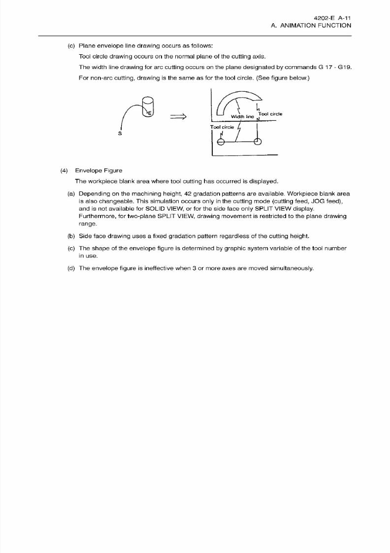
(c) Plane envelope line
drawing occurs
as follows:
Tool
circle
drawing occurs
on
the
normal
plane
of the
cutting
axis.
The width line
drawing for
arc
cutting
occurs on
the
plane
designated
by
commands G 1
7 - G1
9.
For non-arc
cutting, drawing
is the same as for
the
tool
circle.
(See
figure
below.)
I
%
Tool circle
Widlh lir>e
Tool circle
S
(4)
Envelope Figure
The workpiece blank
area
where
tool
cutting has occurred is
displayed.
(a) Depending
on
the machining height, 42 gradation
patterns are available.
Workpiece
blank area
is also
changeable.
This simulation occurs
only in
the
cutting
mode
(cutting
feed,
JOG
feed),
and is not available for SOLID
VIEW,
or for
the
side
face
only
SPLIT
VIEW
display.
Furthermore,
for
two-plane
SPLIT
VIEW, drawing
movement
is restricted
to
the
plane
drawing
range.
(b)
Side face
drawing
uses a fixed
gradation
pattern
regardless
of
the
cutting height.
(c) The shape of
the
envelope figure is determined
by
graphic system
variable of the tool number
in
use.
(d)
The
envelope
figure
is
ineffective
when
3
or
more axes
are moved
simultaneously.
8/15/2019 Okuma Manuals 391
http://slidepdf.com/reader/full/okuma-manuals-391 39/397
4202-E
A-
12
A. ANIMATION FUNCTION
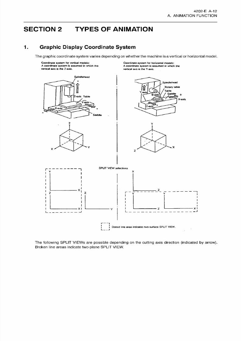
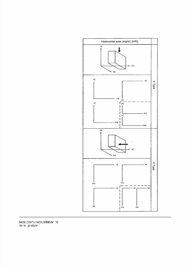
SECTION 2 TYPES
OF
ANIMATION
Graphic
Display Coordinate
System
.
The graphic coordinate
system
varies depending
on whether
the
machine is a vertical or
horizontal
model.
Coordinate
system
(or
verlicaJ
models:
A
coordinate system
is
assumed in
which
the
vertical axis is the
Z-axis.
Coordinate
system
(or
horizontal
models:
A
coordinate
system
is
assumed
in
which the
vertical
axis
is
the Y-axis.
Spindiehead
Spindle
head
Rotary
table
/Table
/ /
Saddle
+
fo)
Y-axis]
8-axis'
tip
Z-axis
Table
—
Y-axis
-
X-axis
(Z-axis
_T
:X-axis
Saddle
Z
Y
i
I
I
X
X
z
SPLIT
VIEW
selections
~l
x
z
r
z
J
L
I
I
Dotted
line
area
indicates two-surlace SPLIT
VIEW.
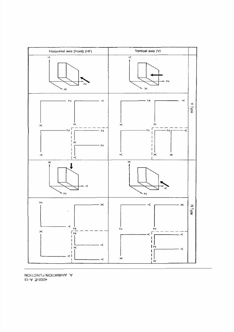
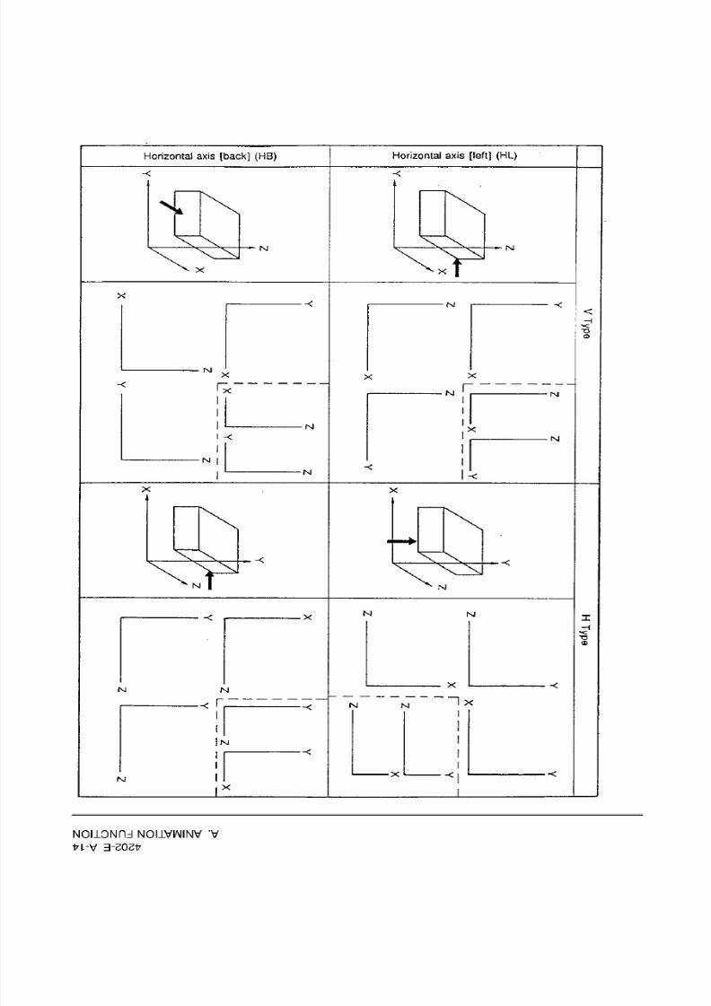
The
following
SPLIT
VIEWs are
possible
depending
on the
cutting
axis
direction
(indicated by arrow).
Broken
line
areas
indicate
two-plane
SPLIT
VIEW.
8/15/2019 Okuma Manuals 391
http://slidepdf.com/reader/full/okuma-manuals-391 40/397
Vertical
axis
(V)
orizontal axis
[front]
(HF)
\
\l
N
V
N
X XI
X
X
x
sj
X
<
H
X
M
r
N
fsi
X
X
X
Xv
X
N
fsl
N
X
X
N
X
rx
xT
x
l
X
I
N
X
I
1*
NOIlONHd
NOI1VIAIINV
'V
SkV
3-ZOZV
8/15/2019 Okuma Manuals 391
http://slidepdf.com/reader/full/okuma-manuals-391 41/397
Horizontal
axis
[left]
(HL)
orizontal
axis
[back]
(HB)
-<
-<
T
XX.
N1
NJ
X
X
X
M
<
H
(D
N
X
X
fx
N
T
INI
N
N
N
N
lx
X
XX
x
Nl
|Ni
INI
N
X X
X
X
N
fNJ
N
x
X
INI
I
IN
I
l
x
X
I
I
NOLLONHd
NOIIVWINV
V
U-V
3-20217
8/15/2019 Okuma Manuals 391
http://slidepdf.com/reader/full/okuma-manuals-391 42/397
Horizontal
axis
[right]
(HR)
X
i
\
N
X
X
-<
<
NJ
X
M
M
INJ
i
X
X
X
NJ
X
X
;g
N
NJ
X
X
X
N
NJ
I
NOLLONRd
NOIIVWINV
V
QkV
3-20217

8/15/2019 Okuma Manuals 391
http://slidepdf.com/reader/full/okuma-manuals-391 43/397
4202-E A-
16
A.
ANIMATION
FUNCTION
Explanation
of
Animation
Related
Functions
.
AUTO
OPERATION
TRACE
/ANIMATE
TOOL
KIND
GRAPHIC
ERASE
HIGH
DRAW
DATA
ON/OFF
RAPHIC
MATERIAL [EXTEND]
GRAPHIC
DATA
AUTO
SCALE
AREA
CHANGE
ANGLE
CHANGE
RAPHIC
[EXTEND]
MDI
OPERATION
TRACE
/ANIMATE
TOOL
KIND
GRAPHIC
ERASE
DATA
ON/OFF
HIGH
DRAW
RAPHIC
MATERIAL [EXTEND]
GRAPHIC
DATA
AUTO
SCALE
AREA
CHANGE
ANGLE
CHANGE
RAPHIC
[EXTEND]
MANUAL OPERATION
TRACE
/ANIMATE
TOOL
KIND
GRAPHIC
ERASE
DATA
ON/OFF
HIGH
DRAW
RAPHIC
MATERIAL
[EXTEND]
AUTO
SCALE
GRAPHIC
DATA
AREA
CHANGE
ANGLE
CHANGE
RAPHIC
[EXTEND]
8/15/2019 Okuma Manuals 391
http://slidepdf.com/reader/full/okuma-manuals-391 44/397
4202-E
A-
17
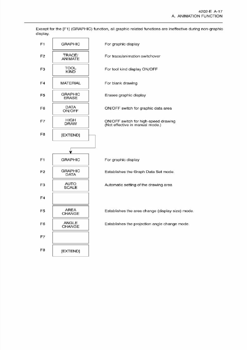
A. ANIMATION FUNCTION
Except for
the [F1]
(GRAPFIIC) function, all
graphic
related functions are
ineffective during non-graphic
display.
F1
GRAPHIC
Fo r
graphic display
TRACE/
ANIMATE
2
For
trace/animation
switchover
TOOL
KIND
3
Fo r
tool kind
display
ON/OFF
F4 MATERIAL
Fo r
blank
drawing
GRAPHIC
ERASE
5
Erases
graphic display
DATA
ON/OFF
ON/OFF
switch
for
graphic
data
area
6
HIGH
DRAW
7
ON/OFF
switch
for
high-speed drawing
(Not
effective
in
manual
mode.)
F8
[EXTEND]
F1
GRAPHIC
Fo r
graphic display
GRAPHIC
DATA
2
Establishes the
Graph
Data Set mode.
AUTO
SCALE
Automatic
setting
of the
drawing
area
3
F4
AREA
CHANGE
F5
Establishes the area
change (display size)
mode.
ANGLE
CHANGE
6 Establishes the
projection angle change
mode.
F7
F8
[EXTEND]
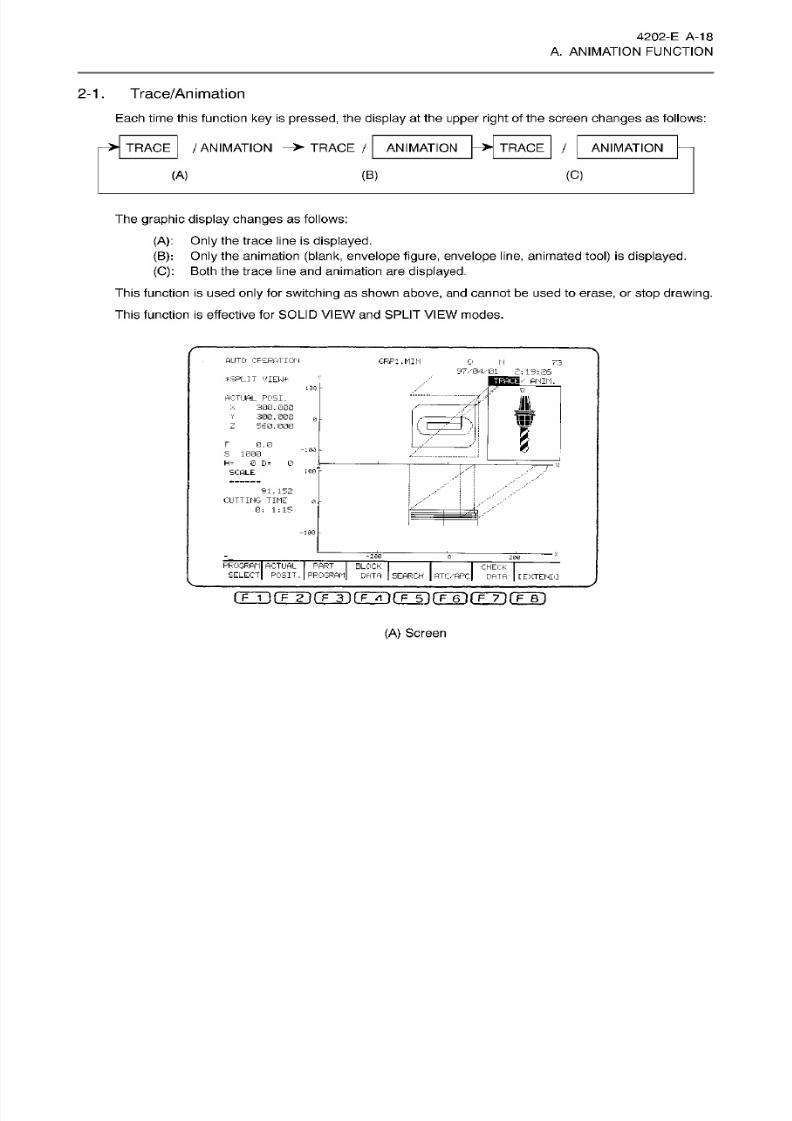
8/15/2019 Okuma Manuals 391
http://slidepdf.com/reader/full/okuma-manuals-391 45/397
4202-E A-
18
A.
ANIMATION
FUNCTION
2-1.
Trace/Animation
Each time
this
function
key
is
pressed,
the
display
at
the
upper
right of
the screen
changes
as
follows:
>
TRACE
>
TRACE
/
ANIMATION
TRACE
/
ANIMATION
ANIMATION
(C)
A)
(B )
The
graphic
display changes
as follows:
(A): Only
the trace line
is
displayed.
(B): Only
the animation
(blank, envelope
figure,
envelope
line, animated tool) is
displayed.
(C):
Both the
trace
l ine and animation are
displayed.
This
function
is used
only
for
switching
as
shown
above,
and
cannot
be used to
erase,
or
stop
drawing.
This
function
is
effective for SOLID
VIEW
and
SPLIT
VIEW
modes.
AUTO OPERATION
GRP:.
MIN
0
N
73
97/04701
_
2;
19:26
pnih-
*
SPLIT
VIEW*
13Q
z
CTUAL
POSI.
X
300.000
Y
30G.0G 0
Z 560.000
ill
H it
III/
B
0.0
-
0
1GB
r
S 1000
H=
0 D=
SCALE
F
91.152
CUTTING
TIME
0: 1:15
0
-100
-200
0
206
PROGRAM ACTUAL
PART
SELECT
POSIT. PROGRAM
BLOCK
DATA
SEARCH
ATC-'APC
CHECK
DATA
[EXTENDI
rrTirrFirÿiÿÿrÿrFÿrr7irF~Bi
(A )
Screen
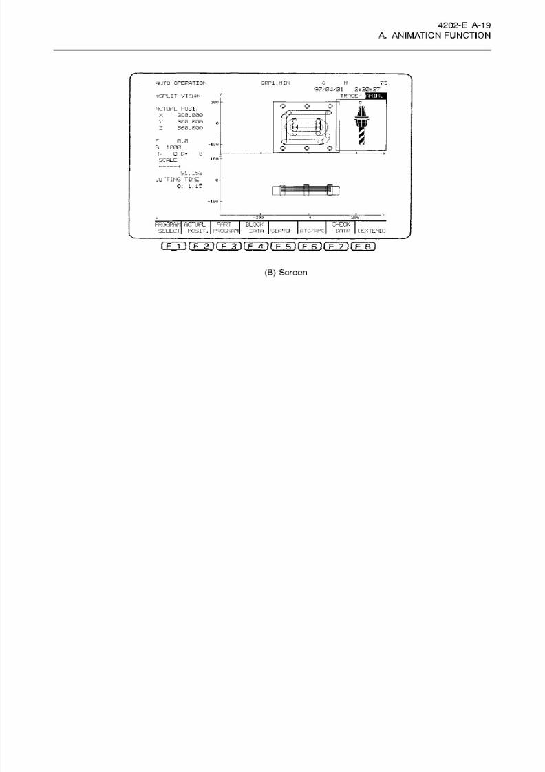
8/15/2019 Okuma Manuals 391
http://slidepdf.com/reader/full/okuma-manuals-391 46/397
4202-E
A-19
A.
ANIMATION
FUNCTION
o
N
73
UTO OPERATION
GRP1.MIN
97X04/01
2:70:27
y
TRACE.'
ANIN .
SPLIT
VIEW*
100
O
O
o
JL
CTUAL POSI.
300
.
000
300
.
000
560
.
000
X
lBBf
0
\1V/
p)
I
.
0.0
D- '
-les
3
1000
H-
0 D=
0
SCALE
O
o
o
X
100
*
91
.
152
CUTTING
TIME
0;
1i
15
0
-100
20020 0
0
CHECK
DATA
FROGR
AN ACT UAL FART
BLOCK
SELECT
POSIT. PROGRAM-
EATA
SEARCH
ATC/APC
I
EXTENDI
i
F
1
)fm(
f
3)rFTi']rr5i(T~6ifF~7irF~Bi
(B )
Screen
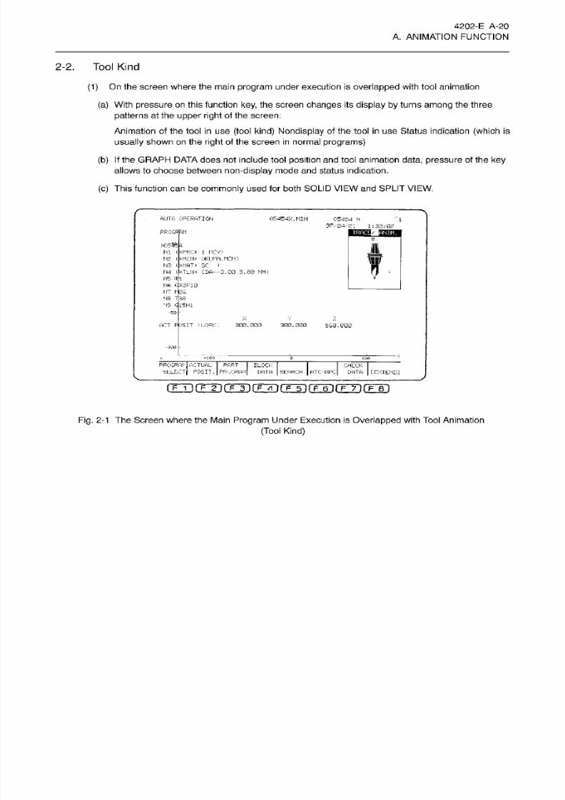
8/15/2019 Okuma Manuals 391
http://slidepdf.com/reader/full/okuma-manuals-391 47/397
4202-E A-20
A. ANIMATION FUNCTION
2-2.
Tool
Kind
(1)
On
the
screen where
the main program
under execution is
overlapped
with tool
animation
(a)
With
pressure
on
this
function key,
the screen
changes
its
display by
turns
among
the three
patterns
at the
upper
right
of
the
screen:
Animation
of
the tool
in
use
(tool kind) Nondisplay
of the tool
in
use
Status indication
(which is
usually shown on
the
right of
the
screen in normal programs)
(b) If
the GRAPH
DATA
does
not
include tool
position and tool animation
data,
pressure
of
the
ke y
allows
to
choose
between non-display mode and status indication.
(c)
This
function
can be
commonly
used
for both
SOLID VIEW
and
SPLIT
VIEW.
AUTO
OPERATION
05454X.
MIN
05454
N
97-'04/ei
1:33:02
1
PROGRAM
W553B4
Ml
<*PRC*
1 MCVJ
N2
t*MCN* OKLIMft.
MCN)
N3
<#MAT*
SC
N4
<
»<TLN*
CDA--3.00 3.00
Ml)
N5
Efl
NS
G30P10
N7
has
MS
T
33
N 9 G 15 H1
)
/
-5Q
X
V z
ACT POSIT
fkOPK;
300.000
300.000
560.000
-100
“ie6 &
PROGRPh
ACTUAL PART
SELECT POSH
.
PRCCRAM
BLOCK
DATA
SEARCH
ATC/flPC
CHECK
DATA
[EXTEND]
(F
i
)(Fiÿro](7ÿ(TT)rFT)rÿ7‘)rF~B4
Fig. 2-1
The Screen where the Main
Program
Under Execution is Overlapped with Tool Animation
(Tool
Kind)
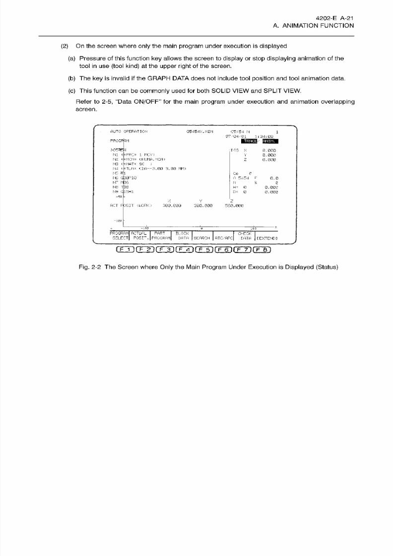
8/15/2019 Okuma Manuals 391
http://slidepdf.com/reader/full/okuma-manuals-391 48/397
4202-E
A-21
A. ANIMATION FUNCTION
(2 )
On
the screen where
only
the
main
program
under execution
is displayed
(a) Pressure of this function
key
allows the
screen
to
display
or
stop displaying
animation of the
tool in
us e
(tool
kind)
at the
upper
right
of the screen.
(b) The
key
is
invalid
if the
GRAPH DATA does not include tool position and tool animation data.
(c) This
function can
be
commonly
used for both SOLID
VIEW
and SPLIT
VIEW.
Refer to
2-5,
“Data
ON/OFF”
for
the main
program
under execution and
animation
overlapping
screen.
AUTO
OPERATION
05454X.I1IN
C54
54
M
97
04.- 01
1
;
34
;
SB
1
PRQGFftM
HI
(
fcPRC*
1 M
CV)
N2
OKLMA.MCN)
N3
':*MHT* SC
J
N4 i.
*TLM* CDA—3 .00 3 .00
MM)
M5
t*=- G30P1G
rr 1*06
HS
7
38
N9 G15H1
MS X
0.000
0.000
0.000
Y
Z
Co
0
0
5454
-
0.0
N
S
e
H=
0
0.000
0.000
=
0
-50
Y
z
AC T
POSIT
(WORK)
300.000
300.000
560.000
103
PROGRAM ACTUAL
PART
BLOCK I
SELECT
P0SI“.
PROGRAM
DATA
SEARCH
ATC/APcI
CHECK
DATA
[EXTENDI
rÿ fTÿ(Tÿ(TTT7fFT1(TT) fTÿrF~r i
Fig.
2-2
The
Screen
where Only the Main Program
Under
Execution is Displayed (Status)
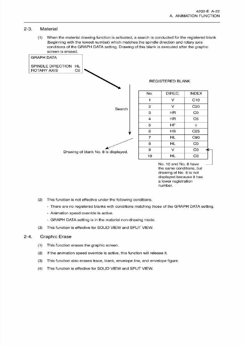
8/15/2019 Okuma Manuals 391
http://slidepdf.com/reader/full/okuma-manuals-391 49/397
4202-E
A-22
A. ANIMATION FUNCTION
2-3. Material
(1)
When
the
material
drawing
function
is
activated,
a
search
is
conducted
for
the
registered
blank
(beginning with
the
lowest number)
which
matches the spindle
direct ion and rotary
axis
conditions of the
GRAPH
DATA
setting.
Drawing of
this blank
is executed
after
the graphic
screen
is erased.
GRAPH DATA
SPINDLE
DIRECTION
HL
ROTARY
AXIS
CO
REGISTERED
BLANK
No.
DIREC.
INDEX
V
C10
C20
Search
HR
CO
HR
C5
HF
*
HB
C25
y
HL
C90
HL
CO
V CO
Drawing
of
blank No. 8 is
displayed.
10
HL
CO
No.
10
and
No.
8
have
the
same
conditions,
but
drawing
of No.
8
is
not
displayed
because it ha s
a
lower
registration
number.
(2)
This
function is
not
effective
under
the
following
conditions.
-
There are
no registered
blanks with
conditions matching those
of the GRAPH
DATA setting.
-
Animation
speed
override
is
active.
-
GRAPH
DATA setting
is
in
the material
non-drawing
mode.
(3)
This function is effective for SOLID
VIEW
and SPLIT
VIEW.
2-4.
Graphic Erase
(1 )
This
function
erases the
graphic
screen.
(2 ) If
the
animation
speed
override is active,
this
function
will release it.
(3)
This function also
erases
trace,
blank,
envelope
l ine, and
envelope
figure.
(4)
This
function
is
effective for SOLID
VIEW
an d
SPLIT
VIEW.

8/15/2019 Okuma Manuals 391
http://slidepdf.com/reader/full/okuma-manuals-391 50/397
4202-E A-23
A. ANIMATION FUNCTION
2-5. Data
ON/OFF
(1) With pressure on
this function
key, the screen changes
its
display
on
its left side by
turns
among
the three patterns:
Display of the
characters
in the graphic
data,
Nondisplay of
them,
and
Display of the
program under
execution
(2) However,
if
the graphic display
area is
limited, pressing
this
key
alternatively changes
the
display
patterns between
the characters
in
the
graphic
data
an d the
program
under execution.
(3)
This
function
is effective
for both
SOLID
VIEW and
SPLIT
VIEW.
2-6.
High
Draw
This function enables high-speed
drawing.
(1)
High-speed drawing
mode
ON/OFF
occurs
each time
this
function
key is
pressed
in
the
auto,
and manual modes
with
machine lock established.
(2)
With riigh
speed
drawing mode,
animation
occurs at
each block.
Drawing occurs in
the
following
order:
trace,
envelope
line,
an d
envelope
figure.
Animated tool
drawing
does not
occur
at this
time.
(3)
The
high-speed drawing
mode is released
by
NO reset or
program
end.
[Supplement]
1. In
the
high-speed drawing mode,
both the GOO and
G01
commands
designate
straight
line
interpolation
to
the designated
value.
Therefore,
the actual trace
(locus) wih
be different.
2.
During h igh-speed drawing, d isplay occurs
at the upper center portion of the
screen.
3.
The line
connecting
the start and en d
point
of the arc is
displayed
for the
3-dimensional
arc
(including
3-dimensional
coordinate
shift;
G02
and
G03) in
the
high-speed
drawing
mode or on the
cycle
start with
the
return search.
2-7.
Graphic
Data
This is
the function for setting
the graphic drawing
conditions.
(1)
The GRAPH
DATA sett ing mode
can be
entered
f rom either the SPLIT
VIEW
or the SOLID
VIEW. If
entered from SPLIT
VIEW display,
setting data
will
be available
which
applies to
the
SPLIT
VIEW only,
as
well
as
data which
applies
to both
the SPLIT
VIEW
and
SOLID
VIEW
displays.
If the
GRAPH
DATA
setting
mode is
entered
from
the
SOLID
VIEW display,
the
reverse
applies.
(2)
Setting data
which
applies
only to the
SPLIT
VIEW
display
is
called ‘SPLIT
VIEW
setting
data’,
setting data which
applies
only to the
SOLID
VIEW display
is
called
‘SOLID
VIEW setting
data’,
and
setting
data which applies to both
is
called 'common
data’.
(3)
The
GRAPH
DATA settings
consist
of
7
pages. Pages
5
through 7
are
reserved
for
data where
infrequent
settings
are
made,
and access to these pages
is restricted
unless
the
PAGE
LIMIT
setting
on
page
3
is set to
NONE
(no page
limit).
If
this
setting
is
EXIST, the
system
will
not
proceed
beyond page 4.
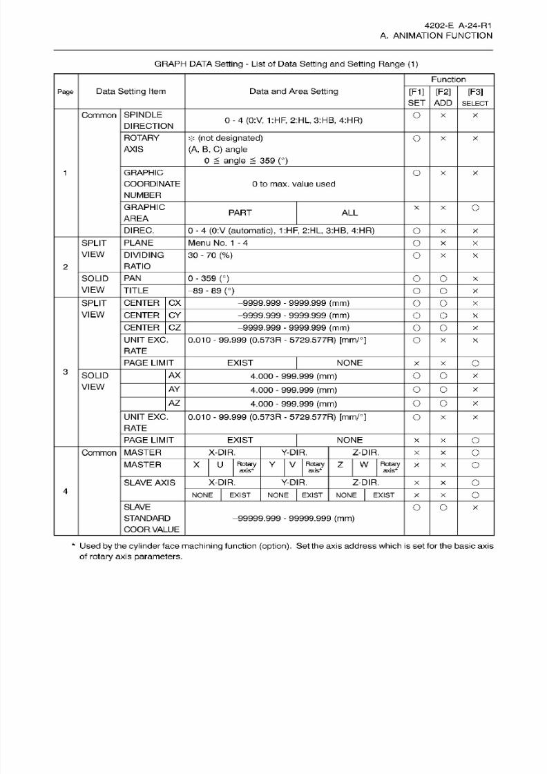
8/15/2019 Okuma Manuals 391
http://slidepdf.com/reader/full/okuma-manuals-391 51/397
4202-E
A-24-R1
A.
ANIMATION
FUNCTION
GRAPH DATA
Setting
- List of Data
Setting
an d
Setting
Range
(1)
Function
Data
Setting
Item
Data
an d
Area Setting
[F1]
[F2] [F3]
age
SET
ADD SELECT
SPINDLE
DIRECTION
Oommon x
0
-
4
(0:V,
1:HF,
2:HL,
3:HB,
4:HR)
ROTARY
*
(not designated)
(A,
B,
C)
angle
0
angle
359
(°)
O
x
AXIS
GRAPHIC
COORDINATE
NUMBER
O
x
0
to
max.
value
used
GRAPHIC
AREA
O
X
PART AL L
DIREC.
0
-
4 (0:V
(automatic),
1:HF,
2:HL,
3:HB, 4:HR)
O
x
SPLIT
VIEW
PLANE
Menu
No. 1
-
4
O
x
X
DIVIDING
RATIO
30
-
70
(%)
O
x
X
2
PAN
0 - 359 (°)
OLID
VIEW
O o
x
TITLE
89
-
89 (°)
O
o
x
CENTER CX
PLIT
VIEW
-9999.999
-
9999.999
(mm)
O
O
x
CENTER
CY -9999.999
-
9999.999
(mm)
O O
x
CENTER CZ
-9999.999
-
9999.999
(mm)
O o
x
UNIT
EXC.
RATE
0.010
-
99.999
(0.573R
- 5729.
577R)
[mm/°]
O
x
X
PAGE
LIMIT
EXIST NONE
O
X
3
AX
OLID
VIEW
O o
.000
-
999.999
(mm)
x
AY
O
O
.000
-
999.999
(mm)
x
AZ
O o
.000
-
999.999
(mm)
x
UNIT EXC.
RATE
0.010 - 99.999 (0.573R -
5729.
577R)
[mm/°]
O
x
PAGE
LIMIT
EXIST NONE
O
X
MASTER
ommon
X-DIR. Y-DIR.
Z-DIR.
O
X
MASTER
X
U
Rotary
axis*
Y V
Rotary
z
w
Rotary
axis*
o
x
axis*
SLAVE AXIS
X-DIR. Y-DIR. Z-DIR.
O
X
4
o
ONE EXIST NONE EXIST NONE
EXIST
X
X
SLAVE
STANDARD
COOR.VALUE
O
o
x
-99999.999
-
99999.999
(mm)
*
Used
by
the
cylinder
face
machining
function
(option).
Set the axis address which
is
set for the basic axis
of
rotary
axis
parameters.
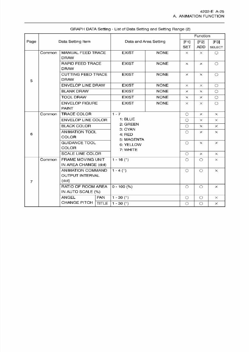
8/15/2019 Okuma Manuals 391
http://slidepdf.com/reader/full/okuma-manuals-391 52/397
4202-E
A-25
A.
ANIMATION
FUNCTION
GRAPH DATA
Setting
- List of Data
Setting
an d
Setting
Range
(2)
Function
Page
Data
Setting
Item Data
and
Area Setting
[F
1] [F2]
[F3]
SE T
ADD SELECT
Common
MANUAL
FEED
TRACE
DRAW
EXIST
NONE
O
x
RAPID FEED
TRACE
DRAW
EXIST
NONE
O
x
CUTTING
FEED
TRACE
DRAW
EXIST
NONE
O
X
5
ENVELOP LINE DRAW
EXIST
NONE
O
x
BLANK D RAW
EXIST
NONE
O
x
TOOL
DRAW
EXIST
NONE
O
x
ENVELOP
FIGURE
PAINT
EXIST NONE
O
x
Common TRACE
COLOR
1
-
7
O
x X
1:
BLUE
2:
GREEN
3: CYAN
4:
RED
5: MAGENTA
6:
YELLOW
7: WHITE
ENVELOP
LINE
COLOR
O
x x
BLACK COLOR
O
x x
ANIMATION TOOL
COLOR
O
x X
6
GUIDANCE TOOL
COLOR
O
x X
SCALE
LINE
COLOR
O
x X
Common
FRAME
MOVING UNIT
IN AREA CHANGE (dot)
1
-
16
n
o o
X
ANIMATION
COMMAND
OUTPUT
INTERVAL
1
-
4(°)
O o
x
(dot)
7
0-100 (%)
ATIO
OF ROOM
AREA
IN
AUTO SCALE (%)
O O
x
ANGEL
CHANGE PITCH
[JITLE
PAN 1 -30
(°)
O
O
x
1
-
30
n
o O
x
8/15/2019 Okuma Manuals 391
http://slidepdf.com/reader/full/okuma-manuals-391 53/397
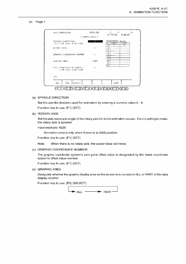
8/15/2019 Okuma Manuals 391
http://slidepdf.com/reader/full/okuma-manuals-391 54/397
4202-E
A-27
A. ANIMATION FUNCTION
(4) Page 1
GRP1.MIH
0
N s
UTO
OPERATION
97/04/01
2:08:27
*
GRAPH
DATA
*
REGISTERED
BLANKPINDLE DIRECTION
0 : V
1
:HF 2:HL
3:
HE
4;HR
DIREC.
_V-
o.
1
*
OTARY
AXIS 2
4
GRAPHIC COORDINATE
NUMBER
5
b
7
PART
_8
RAPHIC
AREA
9
10.
TOOL
DIRECTION
0;V(AUTO)
1 :
HF
£';HL
3:HB
4:
HR
V
=GD
SET
ADD
SELECT
GUIT
(T~T)
(Tÿl
fTTl
fF~T)(Tÿ
(T~6l fF~7~)
f?~Bl
(a)
SPINDLE DIRECTION
Set
the
spindle direction used
for animation
by
entering a
numeric
value
0
- 4.
Function key
to use: [F1]
(SET)
(b)
ROTARY
AXIS
Set the
axis
name
and
angle
of the
rotary
axis
for
which
animation
occurs. If
a
(>]<)
setting
is
made,
the rotary
axis is ignored.
Input example: A230
Animation
occurs
only
when A-axis
is
at
2300 position.
Function
key
to
use:
[F1]
(SET)
Note: When there is no
rotary
axis,
the
cursor
does notmove.
(c)
GRAPHIC
COORDINATE
NUMBER
The
graphic
coordinate
system’s
zero
point
offset value is
designated by
the blank coordinate
system’s
offset value number.
Function
key
to
use:
[F1]
(SET)
(d)
GRAPHIC
AREA
Designate whether the
graphic display
area on
the
screen
is
to consist
of
ALL
or
PART
of
the
data
display
column.
Function
ke y
to
use: [F3]
(SELECT)
PART
LL
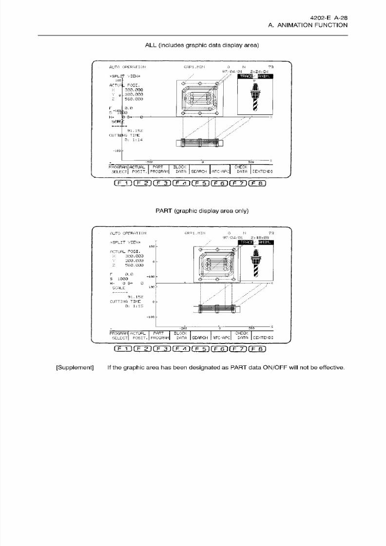
8/15/2019 Okuma Manuals 391
http://slidepdf.com/reader/full/okuma-manuals-391 55/397
4202-E
A-28
A.
ANIMATION
FUNCTION
ALL
(includes
graphic
data
display
area)
AUTO
OPERATION
G.RP1.
MIN 0 H 7.3
97/04
.-'01
2:24:04
a/
SFLfT
VIEW*
TRACI
ANIM.
100
©-
W
CTU-
_
POSI.
300
.
000
.300-000
560.000
>:
B
mr
o
wav
\
0.0
£2/
f
S
10
DB
0- Q
€*
H= e
n
91.152
MG TIME
0:
1:14
CUTIS
-16®
3G0
336
0
BLOCK
DATA
SEARCH
CHECK
DATA
[EXTEND]
PROGRAM ACTUAL
PART
SELECT POSIT
.
PROGRAM
AT
C/
AR C
i
F
1
ifTTii
f
3)f~FTt']rFTnrF~6]fF~7]rFTn
PART
(graphic display
area
only)
GPP
1 . MIN 0 N
73
UTO OPERATION
97/04/01
2: 18:03
a
RACI
ANIM.
ÿSPLIT
VIEW*
100
7
&
&
CTUAL
POSI.
300.000
300.000
560. GOO
fa
L
2
7T 7
mr
i
war
I
F
0.0
-100
S 1000
0
D= 0
0:
©-ÿ
H=
100
r
CALE
r
*
91.152
CUTTING
TIME
0: 1:15
e
-
;
-100
200
200 0
CHECK
4TC/APC L'ATA
PROGRAM ACTUAL
PART
i
SELECT
POSIT. PROGRAM
BLOCK
DATA
SEARCH
[EXTENDI
rFÿfTÿrÿfFÿrÿfÿrÿ7ifF~T)
[Supplement]
If the
graphic
area has been
designated
as PART data
ON/OFF
will
not
be effective.

8/15/2019 Okuma Manuals 391
http://slidepdf.com/reader/full/okuma-manuals-391 56/397
4202-E
A-29
A. ANIMATION FUNCTION
(5) Page 2
SPLIT
VIEW Setting
Data
AUTO
OPERATION
05454X.
MIN
05454
N
97/04/01
2:57:57
0
*
PLANE SELECT
*
PLANE
V
7
DIVIDING
RATIO
50
• K
-
-EX
-GR
=GD
BET ADD
SELECT
QUIT
(F
1
i fFTi(TÿfTTrirr5ÿiT~6nrF7n(TBi
(a) PLANE
The plane to be displayed is designated by the menu
number.
The
following
displays are possible:
Front face, plane, side
face
1-plane
display,
and 2-plane
display.
(b)
DIVIDING RATIO
When
the
2-plane display
is
designated
as
the PLANE
(item a)),
the
relative proportions
of
the
display areas
for
the 2 planes
must be
designated. This setting value will be the vert ical plane
display
ratio for
the
spindle position
in
relation to the entire
display
area.
The
graphic plane
menu
diagrams
are dilferentforthe
‘H type’ and ‘V type’ models.
For
both models, there are
5
types
of
diagrams depending
on
the page
1 SPINDLE
DIRECTION
setting.
On
the following pages,
all
10
of these
diagrams
are shown.
[Supplement]
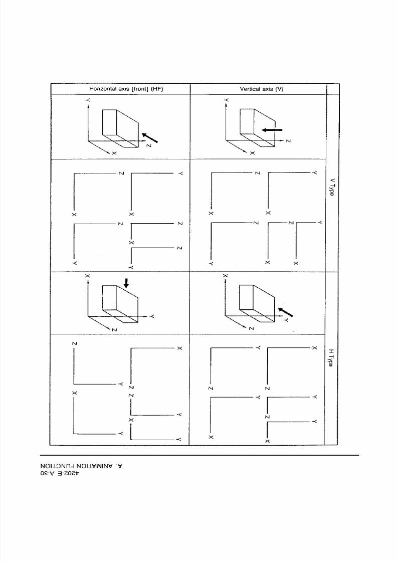
8/15/2019 Okuma Manuals 391
http://slidepdf.com/reader/full/okuma-manuals-391 57/397
Horizontal
axis
[front]
(HF)
Vertical
axis
(V)
X
XN
y
x xl
N
Nl
x
Nl
-<
<
H
-§
o
-<
Jl
J Nl
NJ
X
-<
X
X
X
X
X
x
Nl
Nl
NJ
X
o
NJ
Nl
NJ
X
Nl
X
X
N
X
X
X
NOLLONDd
NOI1VNINV
V
OS-V
3-20217

8/15/2019 Okuma Manuals 391
http://slidepdf.com/reader/full/okuma-manuals-391 58/397
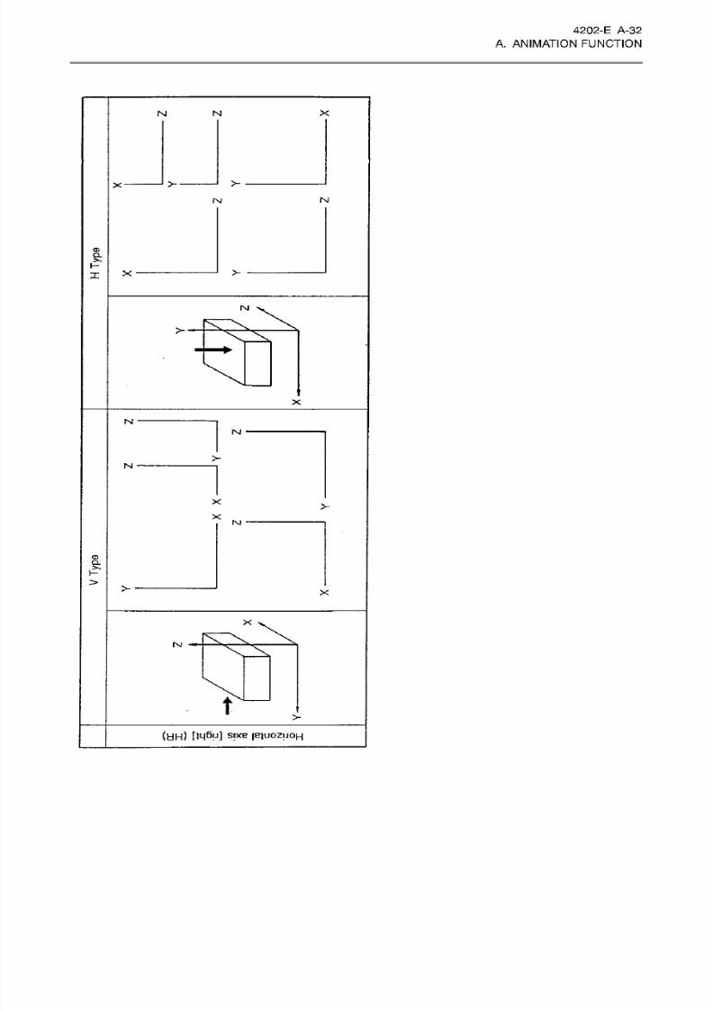
8/15/2019 Okuma Manuals 391
http://slidepdf.com/reader/full/okuma-manuals-391 59/397
4202-E A -32
A.
ANIMATION
FUNCTION
X
I
M
X
INI
NI
<D
o_
X
X
INJ
X
N
X
N
M
CD
CL
>>
>
X
X
X
t
X
(HH) Uÿ\A SIXB
[EIUOZUOH
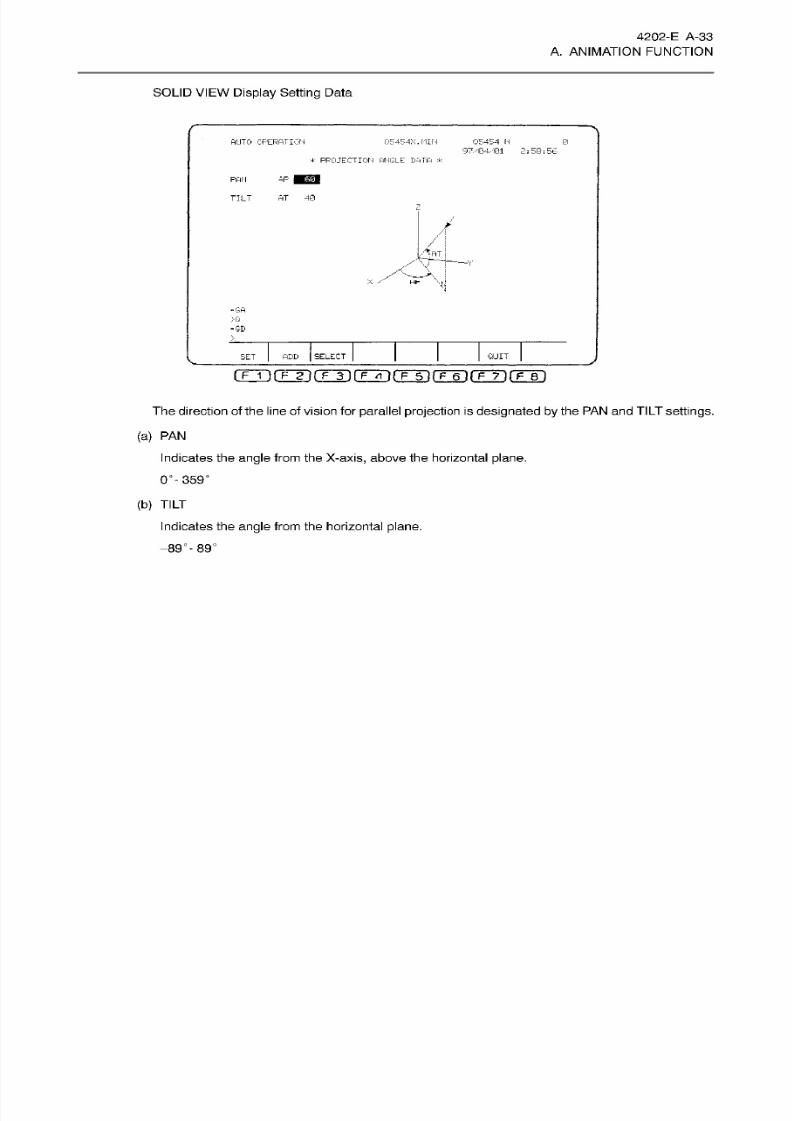
8/15/2019 Okuma Manuals 391
http://slidepdf.com/reader/full/okuma-manuals-391 60/397
4202-E A-33
A. ANIMATION FUNCTION
SOLID
VIEW Display Setting
Data
AUTO OPERATION
G5454X.
MIN
05454
H
97/04,
2
;
53
;
56
a
PROJECT
IO H
ANGLE DATA
*
AP
lEsl
AN
AT
40
ILT
Z
/
/
>:-:T
X
;
-GA
>Q
=GD
ADD SELECT
QUIT
ET
The
direction
of the line of vision for
parallel
projection
is
designated by the PAN and TILT
settings.
(a)
PA N
Indicates the angle
from
the X-axis, above the horizontal plane.
0°- 359°
(b)
TILT
Indicates the angle
from
the horizontal
plane.
-89°-89°

8/15/2019 Okuma Manuals 391
http://slidepdf.com/reader/full/okuma-manuals-391 61/397
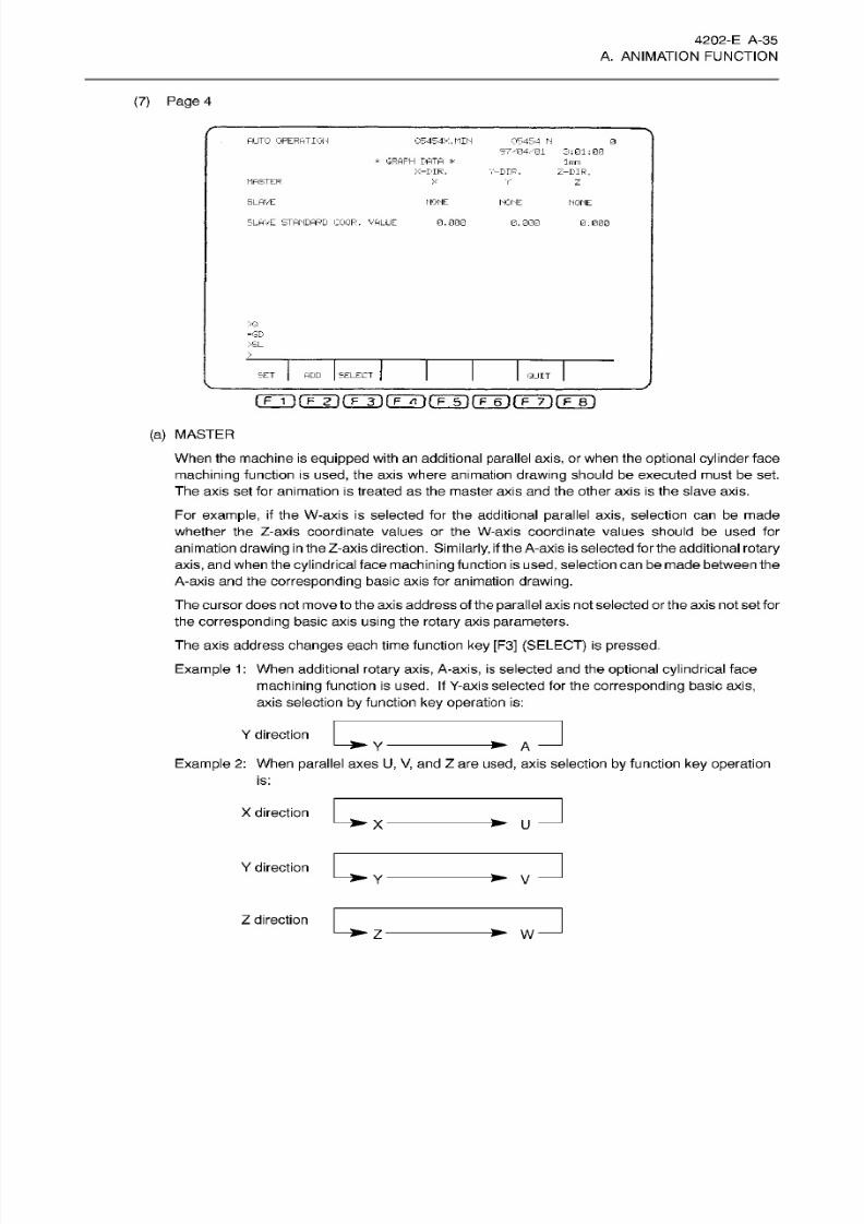
8/15/2019 Okuma Manuals 391
http://slidepdf.com/reader/full/okuma-manuals-391 62/397
4202-E A-35
A. ANIMATION FUNCTION
(7)
Page
4
AUTO OPERATION
05454X.MIN
06454
N
=7/04/01
3:01:00
0
*
GRAPH
DATA
*
-DIR.
1m m
V-DIR.
Z-DIR.
MASTER X
V
z
SLAVE NONE
NONE
NONE
SLAVE
STANDARD
COGR.
VALUE
0.000 0. 000
0.000
xa
-GD
>SL
SET SELECT
DD
QUIT
(TT>(TTirÿiÿnrFTirÿr i rF~T)(TT)
(a)
MASTER
When
the
machine
is
equipped
with an
additional
parallel axis,
or
when
the
optional cylinder
face
machining
function
is
used,
the
axis
where animation
drawing
should be executed
must
be set.
The
axis
set
for animation is
treated
as
the
master axis
and the
other axis is
the slave
axis.
For
example,
if
the W-axis
is
selected
for
the additional
parallel axis,
selection
can
be m ad e
whether the Z-axis coord inate values
or
the W-axis coo rd inate values should be u se d for
animation
drawing in
the Z-axis direction.
Similarly, if
the
A-axis
is
selected
forthe additional
rotary
axis, and
when
the
cylindrical
face
machining
function is
used,
selection
can
be
made
between
the
A-axis and
the
corresponding
basic
axis for animation
drawing.
The cursor does not move to
the
axis address of the
parallel
axis
not
selected or the
axis
not
set
for
the
corresponding basic axis using
the rotary
axis
parameters.
The
axis address changes each time
function
ke y
[F3]
(SELECT) is pressed.
Example
1
:
When additional rotary
axis,
A-axis, is selected
and the
optional
cylindrical
face
machining
function
is used.
If
Y-axis selected
for
the
corresponding
basic
axis,
axis selection
by
function
key operat ion
is:
Y direction
A
Example 2:
When
parallel
axes
U,
V,
and
Z
are
used,
axis
selection
by
function
ke y
operation
is:
X
direction
U
Y
direction
V
Z
direction
W
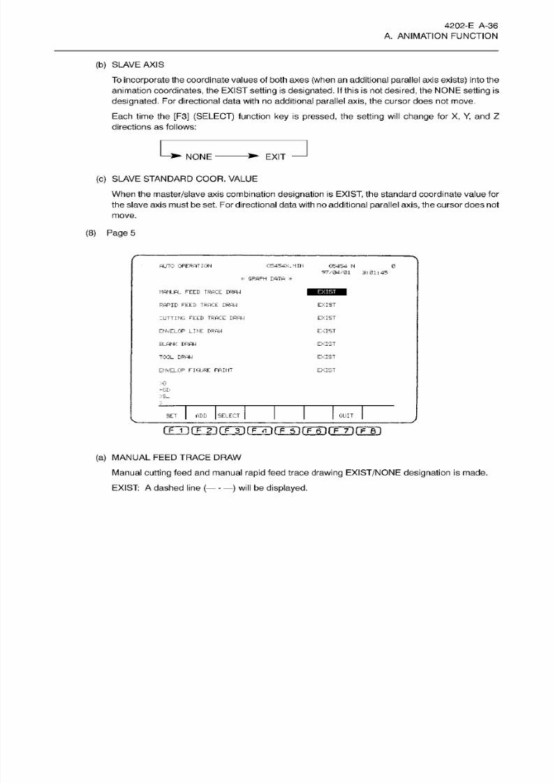
8/15/2019 Okuma Manuals 391
http://slidepdf.com/reader/full/okuma-manuals-391 63/397
4202-E
A-36
A. ANIMATION FUNCTION
(b) SLAVE
AXIS
To incorporate the coordinate values of both axes (when
an
additional parallel axis exists) into the
animation
coordinates,
the EXIST
setting
is
designated.
If
this is not
desired,
the
NONE setting is
designated.
For directional data
with no
additional
parallel axis,
the cursor does not move.
Each time the [F3]
(SELECT)
function
ke y
is pressed, the
setting
will
change
for
X,
Y,
an d
Z
directions
as follows:
1+
EXIT
ONE
(c)
SLAVE
STANDARD
COOR.
VALUE
When
the
master/slave
axis combination
designation
is
EXIST,
the standard coordinate value
for
the
slave axis
must
be set. For directional data
with
no additional
parallel
axis, the
cursor does not
move.
(8)
Page
5
AUTO
OPERATION
05454X.
MIN 05454
N
97/04/01
3:01:45
0
»
GRAPH DATA
*
MANUAL FEED TRACE DRAW
RAPID
FEED
TRACE DRAW
EXIST
CUTTING
FEED TRACE
DRAW EXIST
EXIST
NVELOP
LINE
DRAW
BLANK DRAW
EXIST
EXIST
OOL
DRAW
ENVELOP
FIGURE
PAINT
EXIST
xa
=GD
:>s_
ADD SELECT
QUIT
ET
[~F~I
K
F
2~H
F~3
n
F
tnÿrFÿrrTiprr)
(a)
MANUAL
FEED
TRACE
DRAW
Manual
cutting
feed and manual
rapid
feed trace
drawing
EXIST/NONE
designation
is
made.
EXIST:
A
dashed line
(
---
will
be
displayed.
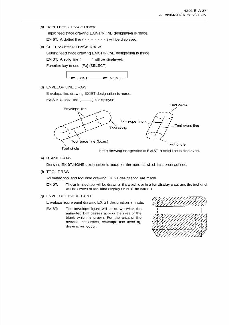
8/15/2019 Okuma Manuals 391
http://slidepdf.com/reader/full/okuma-manuals-391 64/397
4202-E
A-37
A. ANIMATION FUNCTION
(b)
RAPID FEED
TRACE
DRAW
Rapid feed trace
drawing
EXIST/NONE
designation
is made.
EXIST:
A
dotted line {
(c) CUTTING
FEED
TRACE DRAW
Cutting
feed
trace
drawing
EXIST/NONE
designation
is
made.
EXIST:
A solid
line
{
) will be
displayed.
Function
key
to
use: [F3]
(SELECT)
)
will be
displayed.
NONEXIST
(d) ENVELOP LINE
DRAW
Envelope line
drawing
EXIST
designation
is
made.
EXIST:
A
solid
line
{
)
is
displayed.
Tool
circle
Envelope
line
M
Envelope
line
Tool
trace line
Tool
circle
i
i
N
/
\
\
Tool
trace line
(locus)
Tool
circle
Tool
circle
If
the
drawing designation
is
EXIST,
a
solid line
is
displayed.
(e) BLANK DRAW
Drawing
EXIST/NONE
designation is
made
for
the
material which has been defined.
(f) TOOL
DRAW
Animated
tool
and
tool kind drawing
EXIST
designation
are
made.
EXIST:
The animated tool
will
be
drawn at the graphic animation display
area,
and the tool kind
will be
drawn
at tool kind
display
area
of
the screen.
(g)
ENVELOP FIGURE
PAINT
Envelope figure
paint
drawing
EXIST
designation
is
made.
The
envelope
figure
will
be
drawn
when the
animated tool
passes
across the area of the
blank
which is drawn. Fo r
the
area
of
the
material
not
drawn,
envelope
line
(item c))
drawing
will
occur.
EXIST:
i
l
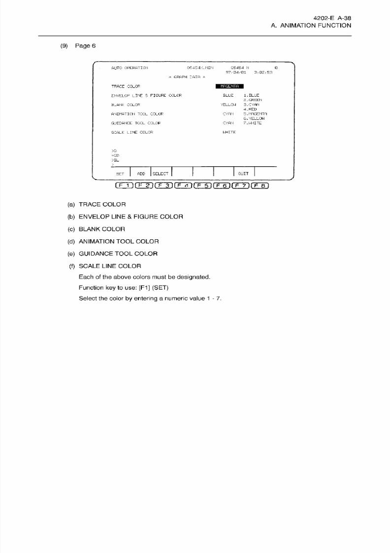
8/15/2019 Okuma Manuals 391
http://slidepdf.com/reader/full/okuma-manuals-391 65/397
4202-E
A-38
A.
ANIMATION
FUNCTION
(9)
Page
6
AUTO
OPERATION 05454M.
MIN
05454 N
97/04/01 3:02:53
G
:*
GRAPH
DATA
*
MAGENTA
RACE COLOR
BLUE
1 .
BLUE
2.
GREEN
3. CYAN
4. RED
5
.
MAGENTA
6. YELLOW
7.
WHITE
ENVELOP
LK C 3- FIGURE
COLOR
'YELLOW
LANK
COLOR
ANIMATION
TOOL COLOR
CYAN
CYAN
UIDANCE
TOOL
COLOR
SCALE
LINE
COLOR
WHITE
>G
=GD
>S L
>
QUIT
ELECTDD
ET
i
F
1
ifTTK
E
3)fÿ4rFinrF~6irF~7ifFir)
(a)
TRACE COLOR
(b)
ENVELOP
LINE
&
FIGURE COLOR
(c)
BLANK
COLOR
(d)
ANIMATION
TOOL COLOR
(e)
GUIDANCE
TOOL
COLOR
(f)
SCALE
LINE
COLOR
Each
of
the
above colors
must
be
designated.
Function
key
to use:
[F1]
(SET)
Select
the
color
by
entering a
numeric
value
1
-
7.
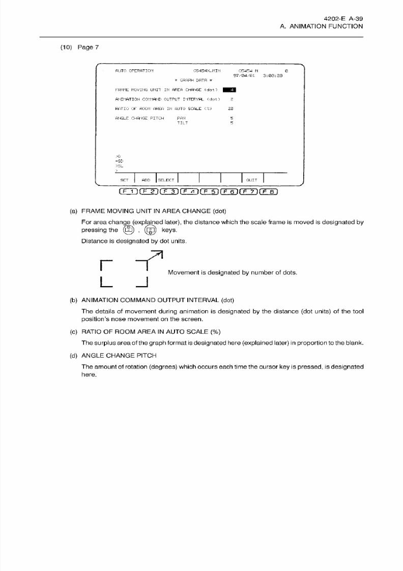
8/15/2019 Okuma Manuals 391
http://slidepdf.com/reader/full/okuma-manuals-391 66/397

8/15/2019 Okuma Manuals 391
http://slidepdf.com/reader/full/okuma-manuals-391 67/397
4202-E A-40
A. ANIMATION FUNCTION
2-8. Auto
Scale
The auto scale function determines the
graphic
area in which
the
blank is drawn automatically.
The auto scale function is as follows:
(1) A registered
blank search
occurs (beginning with lowest registered
number)
for
the
blank with
conditions
which
match the
spindle direction
and
rotary axis
settings
of
the
GRAPH
DATA.
When the blank
is
found,
the
graph
area is automatically
calculated
according
to
the blank
data.
Graph
area
setting is
made
after the
graphic screen
is erased. At
this
time,
a GRAPH
DATA
setting
can be
made for
the surplus
area
aroundthe blank. This
setting
is
made as a
percentage
of the
blank
area.
(2)
The auto
scale
function is
only
effective
fo r the data which
is displayed
while
auto
scale
is
being
executed.
(3)
If no
registered blanks with
the
appropriate
settings
are
found,
a no
blank
data
ERROR
will
occur.
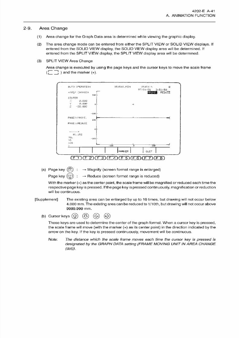
8/15/2019 Okuma Manuals 391
http://slidepdf.com/reader/full/okuma-manuals-391 68/397
4202-E
A-41
A. ANIMATION FUNCTION
2-9. Area
Change
(1)
Area
change for the
Graph
Data
area is
determined while
viewing
the
graphic
display.
(2)
The
area change
mode can
be
entered from either the SPLIT
VIEW
or
SOLID VIEW
displays.
If
entered
from
the SOLID
VIEW
display,
the SOLID
VIEW display area will
be
determined. If
entered
from the
SPLIT VIEW
display,
the
SPLIT
VIEW display
area
will
be
determined.
(3) SPLIT VIEW
Area
Change
Area
change
is executed
by
using
the
page keys
and
the cursor
keys
to
move
the
scale
frame
(
)
and the marker
(+).
AUTO OPERATION
05454X.I1IM
05454 h
97.
E'4-01
3:04:60
H'ftREh
CHANGE*
100
CENTER
X
0.000
Y 0.000
Z
-20.000
0
+
-100
PAGEt
:MAGNI.
100
FAGE1:REDUCE
91.152
>EL
-109
>0
=»;s
4
-20S 3
20Q
MARKER
QUIT
(TTÿrrF)frT)(TTrirrÿrrÿrFÿrF~Bi
(a) Page key
(SB)
:
-»
Magnify (screen
format
range is enlarged)
Page key
(Eg)
:
-* Reduce
(screen
format
range
is
reduced)
With the marker
(+)
as the
center
point,
the scale frame will be
magnified
or
reduced each time the
respective page
key
is
pressed. If the
page
key is
pressed continuously, magnification or reduction
will
be continuous.
[Supplement]
Th e
existing area can
be enlarged by
up
to
10
times,
bu t
drawing will not occur
below
4.000
mm.
The
existing
area canbereduced to
1/1
Oth,
bu t
drawing
will not occur above
9999.999
mm.
(b)
Cursor keys
©
©
© ©
These
keys
are
used to determine the center of the
graph
format.
When a
cursor
ke y is pressed,
the scale frame
will
move
(with
the marker
(+)
as its
center
point)
in
the direction indicated
by
the
arrow
on
the
key.
If
the
key
is
pressed
continuously,
movement
will
be continuous.
Note: The
distance
which
the
scale
frame
moves
each time
the cursor
key
is
pressed
is
designated by
the
GRAPH DATA
setting
(FRAME
MOVING UNIT
IN AREA
CHANGE
(dot)).
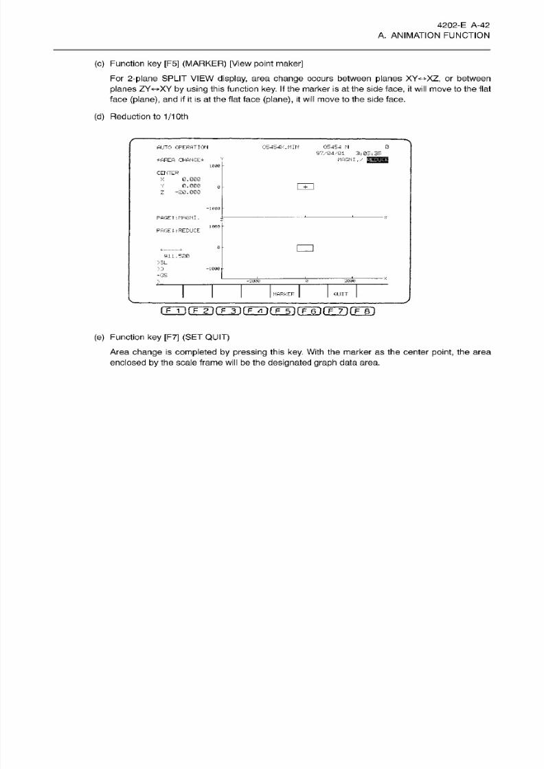
8/15/2019 Okuma Manuals 391
http://slidepdf.com/reader/full/okuma-manuals-391 69/397
4202-E
A-42
A. ANIMATION FUNCTION
(c) Function
ke y
[F5] (MARKER)
[View point
maker]
For 2-plane SPLIT
VIEW display,
area
change
occurs between planes
XY*>XZ,
or between
planes
ZY«-»XY
by
using
this function key. If
the marker is
at the
side
face,
it
will move
to
the
flat
face
(plane),
and
if
it
is at the flat face
(plane),
it
will
move
to the side face.
(d)
Reduction to
1/1
Oth
05454
N
97/04/01
3
:
05 ;
35
MAGNI
. zHMMi
0
UTO
OPERATION
05454X.MIN
*AREA CHANGE*
1000
CENTER
X
0.G00
0.000
Z
-20.000
m
0
-am
PAGEt
:
MAGNI
.
1000
PAGEl
i
REDUCE
o
911.520
>3 L
>:«
-GS
-1000
-2000
-ÿ
28O0
MARKER
QUIT
rrT)f7ÿrÿrFTT)rÿ5irÿ6~)rFÿ~)rF~r)
(e) Function key [F7]
(SET QUIT)
Area change
is
completed by
pressing
this
key.
With
the
marker as th e
center
point,
the
area
enclosed
by
the scale frame
will
be
the designated graph
data area.
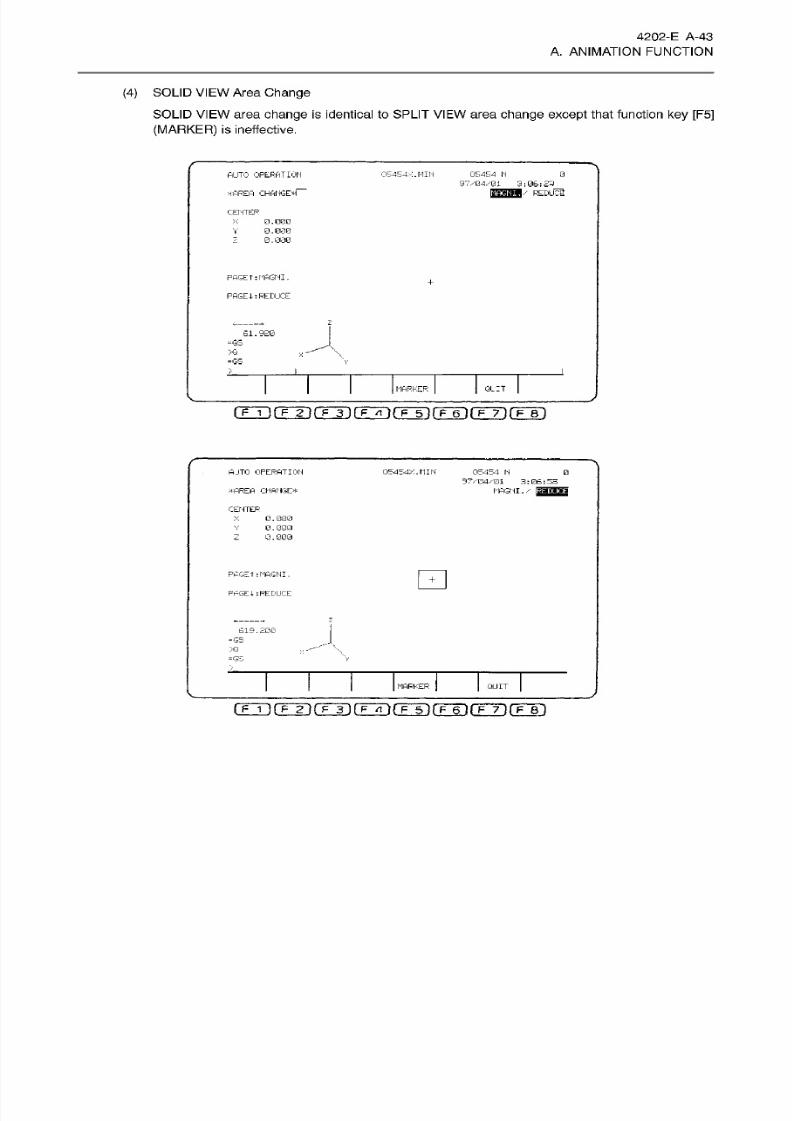
8/15/2019 Okuma Manuals 391
http://slidepdf.com/reader/full/okuma-manuals-391 70/397
4202-E A -43
A.
ANIMATION
FUNCTION
(4)
SOLID VIEW
Area
Change
SOLID VIEW
area
change
is identical to SPLIT
VIEW
area
change
except
that function
key
[F5]
(MARKER)
is ineffective.
AUTO
OPERATION
05454.*:.
MIN 05454 N
97/04/01
3:06:23
0
*AREA
CHANGE* -
U/
REDLICS
CENTER
X 0.000
0.000
0.000
V
z
PHGE
T
:MAGNI
.
+
PAGE :
REDUCE
2
61.920
=G S
\
V
>Q
H
=GS
>
Ql
IT
ARKER
03
)(FSCOT(Xÿ(ÿ31(T~6TrF~7ArF~Bl
A-JTO OPERATION 05454X.MIN
05454
N
97/04/01
3:06:53
MAGNI.
/
gJSSE
0
*AREA
CHANGE*
CENTER
X
0.000
0.000
0.0G0
PAGET:MAGNI .
PAGET
:
REDUCE
z
619.200
=GS
\
>Q
\
«GS V
>
MARKER
QUIT
(
F 1
)(
F
2
It
F
3
][
F A
)(T
5irF~6l(
F~7
If
FBI
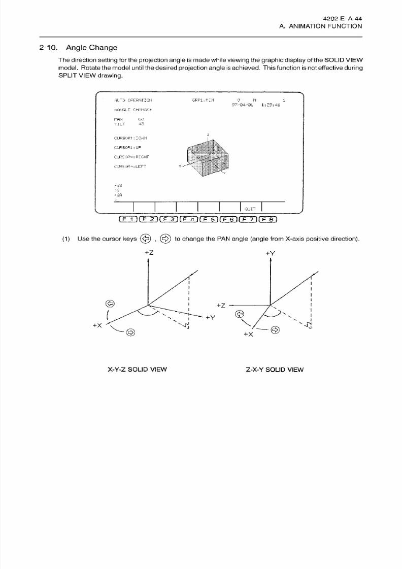
8/15/2019 Okuma Manuals 391
http://slidepdf.com/reader/full/okuma-manuals-391 71/397
4202-E
A-44
A. ANIMATION FUNCTION
2-10.
Angle Change
The
direction
setting
for the
projection
angle is made while
viewing
the
graphic display
of
the SOLID
VIEW
model . Rotate
the
model
until the
desired
projection
angle is
achieved. This function is not effective
during
SPLIT
VIEW drawing.
AL~0 OPERATION
GRPl.l'-IN
i
97.-134/31 1:29:41
WANGLE
CHANGE*
PAN
63
TILT
43
L
OJRSORT
: CCv
IN
.
.»
CURSOR
4 : UP
CURSOR-:
RIGHT
CURSOR-*:LEFT
\
-GS
>0.
-G A
QUIT
(1)
Use the
cursor
keys
,
(ÿ)
to
change
the PAN
angle (angle
from
X-axis
positive
direction).
+Z
+Y
©
+Z
©
Y
V
<3
x
©
+x
X-Y-Z SOLID
VIEW
Z-X-Y SOLID
VIEW
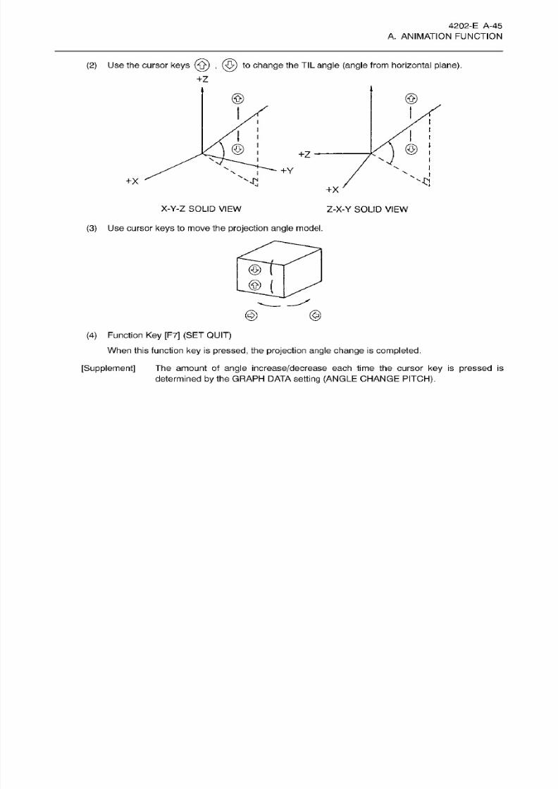
8/15/2019 Okuma Manuals 391
http://slidepdf.com/reader/full/okuma-manuals-391 72/397
4202-E A-45
A. ANIMATION FUNCTION
(2 )
Use
the
cursor
keys
{ÿ)
,
(ÿ)
to
change
the
TIL angle (angle
from horizontal plane).
@
@
© ©
\
+Y
''ÿCl
x
+x
X-Y-Z
SOLID
VIEW
Z-X-Y
SOLID
VIEW
(3)
Use
cursor
keys
to
move the projection
angle
model.
©
©
(
©
©
(4)
Function Key
[F7]
(SET QUIT)
When
this function
key
is
pressed,
the
projection angle change
is
completed.
The
amount
of
angle
increase/decrease
each tim e the cursor ke y
is
pressed
is
determined
by
the GRAPH DATA
sett ing (ANGLE
CHANGE
PITCH).
[Supplement]
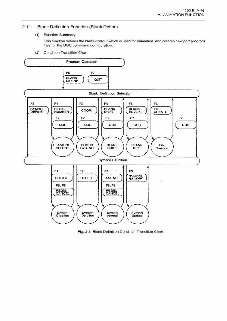
8/15/2019 Okuma Manuals 391
http://slidepdf.com/reader/full/okuma-manuals-391 73/397
4202-E
A-46
A.
ANIMATION
FUNCTION
2-11. Blank Definition
Function
(Blank Define)
(1)
Function
Summary
This function defines
the
blank contour which is
used
for
animation,
and creates
ne w
part
program
files
for th e U GC
command
configuration.
(2)
Condition Transition Chart
)
rogram Operation
F5 F7
DC
BLANK
v
DEFINE
QUIT
V
D
lank
Definition Selection
h
i
,
a
i
•
.
F3
F1
F2 F4
F5 F6
r
BLANK
v
SHIFT
r
FILE
„
CREATE
SYMBOL
,
DEFINE
D
REGIS.
NUMBER
D
) )
D
BLANK
.
ENVLP.
)
OOR.
F7
F7 F7 F7
F7
c
c
c
UIT QUIT QUIT QUIT
QUIT
BLANK
NO.
SELECT
COORD.
SYS. NO .
BLANK
SHIFT
BLANK
SIZE
File
Creation
c
)
ymbol
Definition
i
.
F1
F2
F3
F5
)
)
D
SYMBOL
s
SELECT
REATE DELETE
AMEND
F5.
F6
F5,
F6
REGIS.
S
CANCEL
,
c
c
EGIS.
CANCEL
Symbol
Deletion
Symbol
Creation
Symbol
Amend
Symbol
Update
Fig.
2-3
Blank
Definition Condition Transition Chart
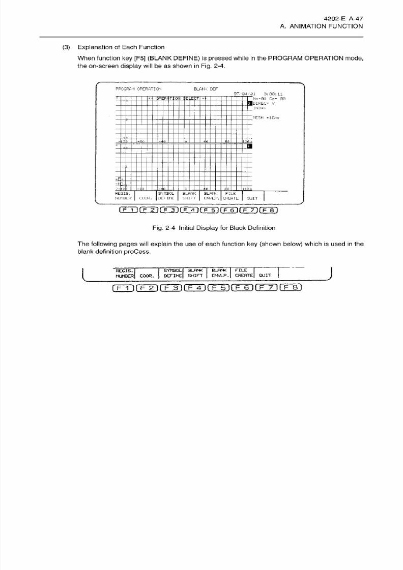
8/15/2019 Okuma Manuals 391
http://slidepdf.com/reader/full/okuma-manuals-391 74/397
4202-E
A-47
A. ANIMATION FUNCTION
(3) Explanation of Each Function
When function
key
[F5] (BLANK DEFINE) is
pressed
while
in the
PROGRAM
OPERATION
mode,
the on-screen display will
be
as
shown
in Fig.
2-4.
PROGRAM
OPERATION
B LA NK D EF
3:
0S: 11
~i
Ho
=01
Co-
00
I
__
DIREC-
V
_
IND=*
F'flRfjlTjO ::E..E
MESH
I -50
=E
SYMBOL
DEFINE
irtr
CREATE
REGIS.
NUMBER
COOR.
BLANK
SHIFT
BLANK
EHVLP.
QUIT
Fig.
2-4 Initial
Display
for Black Definition
The following pages
will
explain the
us e
of each function
key (shown
below) which
is
used
in
the
blank definition
proCess.
J
FILE
CREATE]
QUIT
SYMBOL BLANK
BLANK
DEFINE
SHIFT
ENV1P.
REGIS.
I
NUMBER]
COOR.
rrÿrrÿrrTifrx]fTÿ(Tÿ(TÿrF~8i
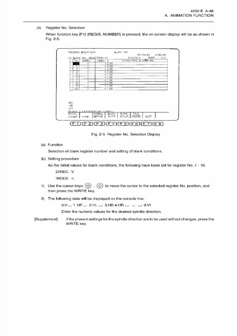
8/15/2019 Okuma Manuals 391
http://slidepdf.com/reader/full/okuma-manuals-391 75/397
4202-E
A-48
A. ANIMATION FUNCTION
(4)
Register
No. Selection
When function
key [F1]
(REGIS.
NUMBER) is
pressed,
the on-screen
display will
be as shown
in
Fig.
2-5.
PROGRAM
OFERATICN
BLANK
DEF
97/04ÿ01
3:08:55
F'AGE 1/1
-flXIS;*
BLANK
No. SELECTION
**
NDEX
COORDINATE:
SYSTEM
NO .
o. BIREC
00
V
00
*
00
V
*
00
_
00
V
*
_6_
00
7
V_
00
*
-ÿn
_v_
V 00
_
*
0
00
=NB
>EN
Select
a
registration
number
SYMBOL
BLANK
BLANK FILE
ENVLP.
CREATE
REGIS.
QUIT
UMBER
COOR. DEFINE
Shi
FT
rrrirrTirFTi(TÿrFTirF~6irF~y)fF~Bi
Fig.
2-5
Register
No. Selection
Display
(a)
Function
Selection
of blank
register
number and setting
of blank conditions.
(b )
Setting
procedure
As the initial values
for
blank
conditions,
the following
have been
set
for register
No. 1-10.
DIREC: V
INDEX:
*
1)
Use
the cursor
keys
{ÿ)
,
(JO)
to
move the cursor to
the
selected
register
No.
position,
and
then
press
the WRITE
key.
2)
The
following
data
will
be
displayed
on
the
console
line:
0:VI_J
1
:HFLJ
2:HL
3:HB4:HR
I_I
LJ
0:V
Enter the numeric
values
for
the desired spindle direction.
[Supplement]
If
the
present settings
for
the
spindle
direction
are to be
used without
changes,
press the
WRITE key.
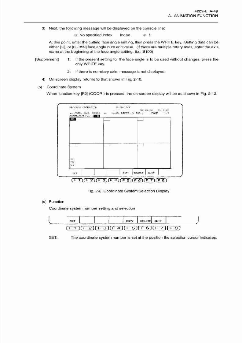
8/15/2019 Okuma Manuals 391
http://slidepdf.com/reader/full/okuma-manuals-391 76/397
4202-E
A-49
A. ANIMATION FUNCTION
3) Next, the
following message will be displayed on
the console line:
T:
No specified index Index
At
this
point,
enter the
cutting
face
angle setting,
then
press
the
WRITE key. Setting
data ca n be
either [> <], or
[0
- 359] face
angle
num-eric
value.
(If
there are multiple
rotary
axes,
enter
the
axis
name at
the
beginning
of
the face
angle sett ing.
Ex.:
B190)
[Supplement] 1
.
If the present
setting
for
the face
angle
is
to
be used without
changes,
press
the
only WRITE key.
2. If
there
is
no rotary
axis,
message
is not
displayed.
4)
On-screen
display
returns to that shown
in Fig.
2-10.
(5)
Coordinate
System
When
function
key
[F2]
(COOR.)
is
pressed,
the on-screen display
will
be
as shown
in
Fig. 2-12.
*
FROGRAM OPERATION
BLANK
LCE
97,
''04/01
3:10:07
**
CORD.
SYS.
DE-SIC.
**
Ho: 01 DIREC: V IND:
*
PAGE
1/1
COORD.
SYS.Ho.
=EX
>C0
CORY
DELETE
QUIT
ET
Fig.
2-6
Coordinate
System
Selection
Display
(a)
Function
Coordinate
system
number
setting
and selection
l
J
OPY
DELETE
QUIT
ET
m ~i
(~F~2i
rr~3i
rFm
rF~6i
rm
fF~8i
SET:
The coordinate
system
number
is
set at the
position
the selection cursor indicates.
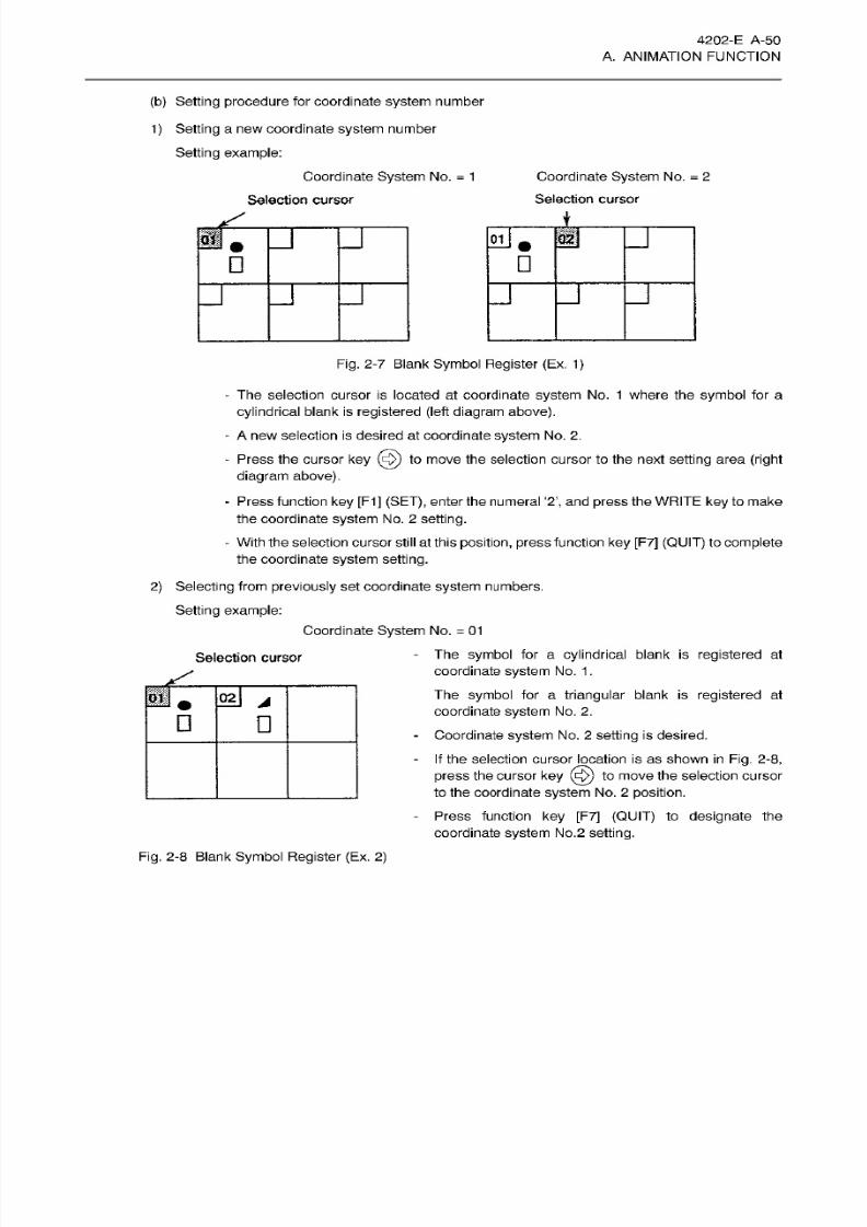
8/15/2019 Okuma Manuals 391
http://slidepdf.com/reader/full/okuma-manuals-391 77/397
4202-E A-50
A. ANIMATION FUNCTION
(b)
Setting
procedure
for
coordinate
system
number
1)
Setting
a
new coordinate
system
number
Setting
example:
Coordinate System No.
=
1
Coordinate System No.
=
2
Selection
cursor
election
cursor
i
if
u
J
Fig.
2-7 Blank Symbol
Register
(Ex.
1)
- The selection cursor is located
at
coordinate system No .
1
where the
symbol
for
a
cylindrical
blank is
registered
(left
diagram
above).
-
A
new selection is desired at
coordinate
system
No. 2.
- Press the
cursor
key
(5)
to move
the
selection
cursor
to
the next
setting
area
(right
diagram above).
-
Press function
ke y
[F1]
(SET),
enter the
numeral ‘2’, and press
the
WRITE key
to make
the
coordinate
system
No .
2 setting.
-
With the selection cursor still at
this
position,
press
function
key
[F7]
(QUIT)
to complete
the coordinate
system sett ing.
2)
Selecting
from
previously
set
coordinate
system numbers.
Setting
example:
Coordinate
System
No.
=
01
The
symbol
for a
cylindrical
blank
is registered
at
coordinate
system
No .
1.
The
symbol
for a
triangular
blank is
registered
at
coordinate
system
No . 2.
Coordinate
system
No.
2
setting
is
desired.
If
the selection
cursor
location
is
as
shown in
Fig.
2-8,
press
the
cursor
key
(ÿ)
to
move
the
selection cursor
to
the coordinate
system
No.
2
position.
Press function
key
[F7]
(QUIT)
to
designate the
coordinate
system
No.2
setting.
Selection
cursor
°*J
A
Fig.
2-8
Blank
Symbol Register (Ex.
2)

8/15/2019 Okuma Manuals 391
http://slidepdf.com/reader/full/okuma-manuals-391 78/397
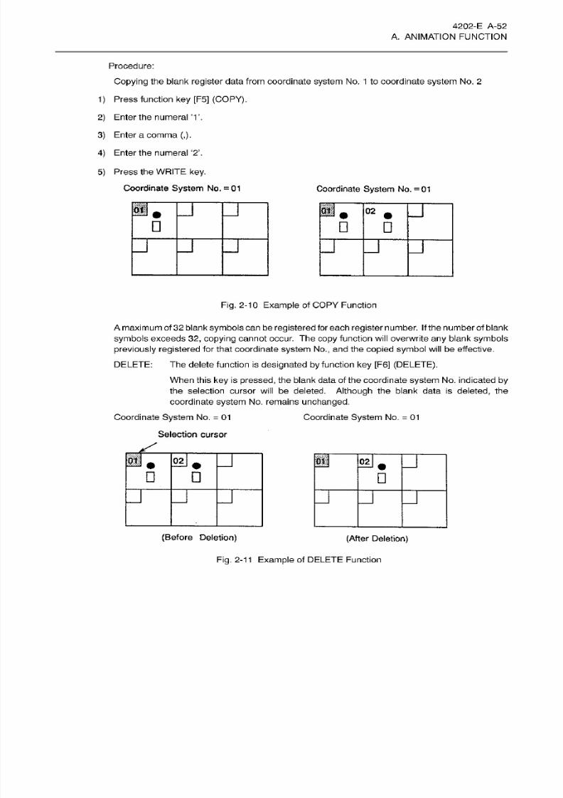
8/15/2019 Okuma Manuals 391
http://slidepdf.com/reader/full/okuma-manuals-391 79/397
4202-E A-52
A. ANIMATION FUNCTION
Procedure:
Copying the
blank
register
data from coordinate
system
No.
1
to coordinate
system
No. 2
1) Press function
ke y
[F5] (COPY).
2) Enter
the
numeral ‘1 ’.
3) Enter
a
comma
(,).
4)
Enter
the
numeral
‘2’.
5)
Press the
WRITE key.
Coordinate System
No.
=
01
Coordinate
System
No .
= 01
J
H.
J
2
n
n
j
Fig.
2-10
Example
of
COPY
Function
Amaximum
of
32
blank
symbols
can
be
registered
for
each register
number.
If the
number
of blank
symbols
exceeds
32,
copying
cannot occur. The
copy
function will overwrite
any
blank
symbols
previously
registered for that coordinate
system
No.,
and the
copied symbol
will be
effective.
DELETE:
The
delete
function
is
designated by
function
key
[F6]
(DELETE).
When
this key
is
pressed,
the blank data
of the coordinate
system
No.
indicated by
the
selection cursor will
be deleted.
Although
the blank
data is deleted,
the
coordinate
system
No. remains
unchanged.
Coordinate
System
No.
=
01
Selection cursor
Coordinate System No.
=
01
02j
if.
J
n
j
u
(Before
Deletion)
(After
Deletion)
Fig.
2-1
1
Example of
DELETE
Function
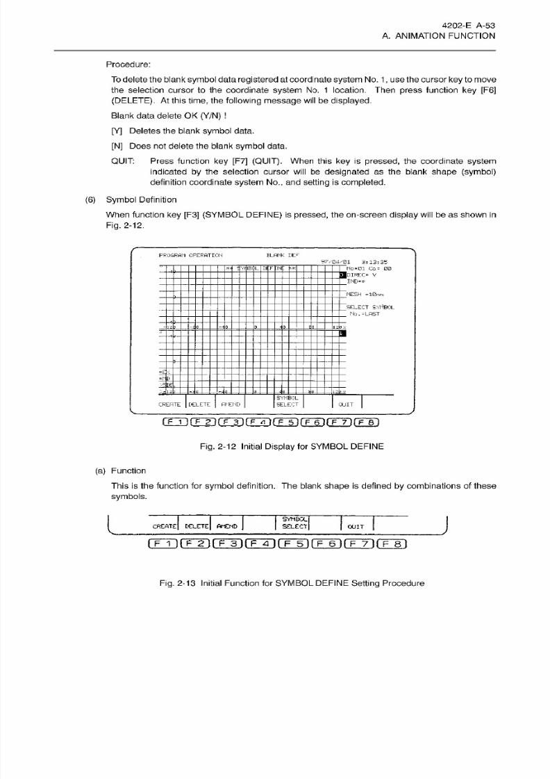
8/15/2019 Okuma Manuals 391
http://slidepdf.com/reader/full/okuma-manuals-391 80/397
4202-E A-53
A. ANIMATION FUNCTION
Procedure:
To delete
the
blank
symbol
data
registered
at coordinate
system
No.
1
, us e the cursor
key
to
move
the selection cursor
to
the
coordinate
system
No . 1
lo ca tio n. T hen
press
function
ke y [F6]
(DELETE).
At
this
time,
the
following
message
will
be
displayed.
Blank data delete OK
(Y/N)
[Y]
Deletes
the
blank
symbol
data.
[N]
Does
not delete the blank
symbol
data.
Press
function
key
[F7]
(QUIT).
When
this
key
is
pressed,
the coordinate
system
ind icated by the selection cursor
will
be
designated as
the blank
shape (symbol)
definition coordinate
system
No.,
and setting
is completed.
QUIT:
(6)
Symbol
Definition
When function
key [F3]
(SYMBOL DEFINE)
is
pressed,
the
on-screen
display will
be
as shown in
Fig.
2-12.
PROGRAM OPERATION BLANK
EE*7
37704ÿ01
3:13:35
Ho -0 1
Co- 00
___
DIREC-
V
____
ND-*
3
r
'I TtF
;
MESH -10mm
SELECT SYfiBOL
.
No.
=LAST
1
a
4-
-
[ -ÿ-
SYMBOL
SELECT
REATE DELETE
AMEND
QUIT
CETTI
(~F~ÿ
(T31
fF~6~)
fF~T) rp~6~)
Fig.
2-12
Initial
Display
for SYMBOL
DEFINE
(a)
Function
This
is the
function
for
symbol
definition.
The
blank
shape
is defined
by
combinations of
these
symbols.
I
J
YMBX
SELECT
REATE DELETE AMEND
QUIT
(TTirFÿ(Tÿ{TÿrF~5~i(~F~6irFTirF~8i
Fig.
2-13
Initial Function
fo r SYMBOL
DEFINE
Setting
Procedure
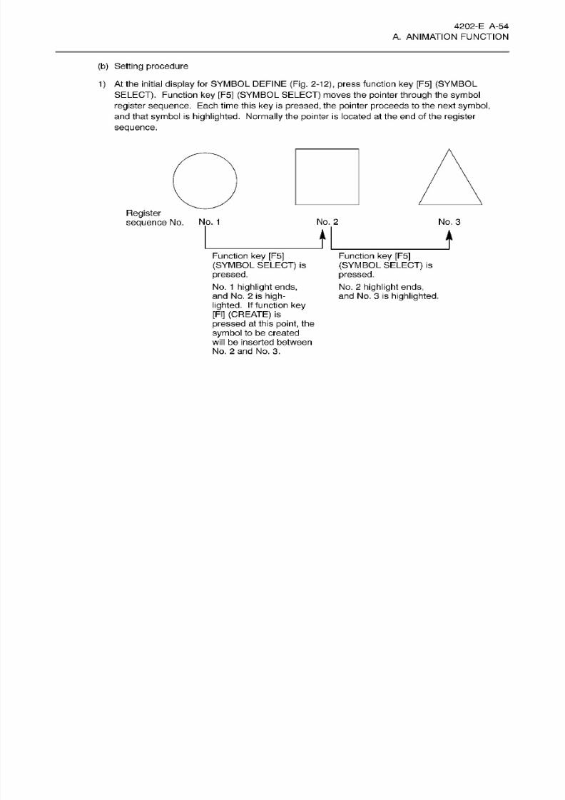
8/15/2019 Okuma Manuals 391
http://slidepdf.com/reader/full/okuma-manuals-391 81/397
4202-E A-54
A. ANIMATION FUNCTION
(b)
Setting
procedure
1) At the
initial
display
for SYMBOL
DEFINE (Fig.
2-12),
press
function
ke y
[F5]
(SYMBOL
SELECT).
Function
ke y [F5] (SYMBOL SELECT) moves
the
pointer
through
the
symbol
register sequence.
Each time this
ke y is
pressed,
the
pointer
proceeds
to
the
next
symbol,
and that
symbol
is
highlighted. Normally
the
pointer
is located at
the
en d
of the
register
sequence.
Register
sequence
No.
No. 1 No.
2
No.
3
I
i
Function
ke y
[F5]
(SYMBOL
SELECT)
is
pressed.
No. 1
highlight ends,
an d No.
2
is
high¬
lighted.
If
function
ke y
[FI]
(CREATE)
is
pressed
at
this
point,
the
symbol
to be created
will
be inserted between
No.
2
and No.
3.
Function
ke y
[F5]
(SYMBOL
SELECT)
is
pressed.
No. 2
highlight
ends,
and
No.
3 is
highlighted.

8/15/2019 Okuma Manuals 391
http://slidepdf.com/reader/full/okuma-manuals-391 82/397
4202-E A-55
A. ANIMATION FUNCTION
2) At the initial
display
for SYMBOL
DEFINE (Fig.
2-18),
press
function
ke y [F1]
(CREATE).
Fig. 2-14
shows the
symbol
select
display.
First,
the symbol
shape
is
determined. Use the
cursor
ke y
to
move the
pointer
to the desired
pattern,
selected from
among
the
8
patterns
displayed
at
the left side of the
screen. ‘With
the
pointer
at the desired
pattern, press
the
WRITE
key,
and this
pattern
is selected.
i
_
m
j
YMBOL
SELECT
QUIT
ELETE WEND
(T~Tÿ (~F~3~)
fF~4~) fÿ~5l
f~F~6~l
(~F~T1
(~F~B~)
PROGRAM
OPERATION
B LA NK DEE
97V04/01
3*
14:
TO
No
=01
Co®
00
—DIREC® V
___
ND-*
'oTl
*4
SY IBOL
DtFtNI
dip
MESH
*
10
mm
I®
SELECT
SYMBOL
.
No.
-LAST
0
T0
• FT
E
1
=
KD_
SYMBOL
SELEET
REfiTE
j
DELETE
AMEND
QUIT
fFÿrrT)(TÿrÿiTÿnÿ6irF~T)rF~8i
Fig. 2-14
SYMBOL
CREATE Function of
Symbol
Select
Display
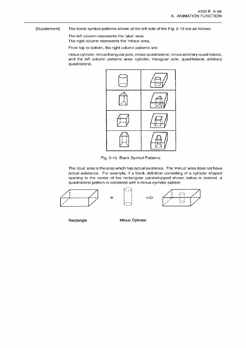
8/15/2019 Okuma Manuals 391
http://slidepdf.com/reader/full/okuma-manuals-391 83/397
4202-E A-56
A. ANIMATION FUNCTION
[Supplement]
The blank
symbol
patterns shown
at
the left side of the
Fig.
2-19 are
as
follows:
The left column
represents
the
‘plus’
area.
The
right
column represents the ‘minus’ area.
From
top
to
bottom,
the
right
column
patterns
are:
minus
cylinder,
minus
triangular
pole,
minus
quadrilateral,
minus
arbitrary
quadrilateral,
and
the left column patterns area: cylinder,
triangular
pole, quadri lateral,
arbitrary
quadrilateral.
Q
fill
few
a
y
&
H
s
Fig.
2-15 Blank
Symbol
Patterns
Th e
'plus’
area
is the
area
which has actual
existence.
The ‘minus’ area
does
not
have
actual existence. For
example,
if
a blank definition
consisting
of a
cylinder
shaped
opening
in
the
center of the
rectangular parallelopiped
shown below is
desired,
a
quadrilateral
pattern
is combined with a
minus
cylinder
pattern.
CM
i*:<
+
/
o
Minus
Cylinder
ectangle
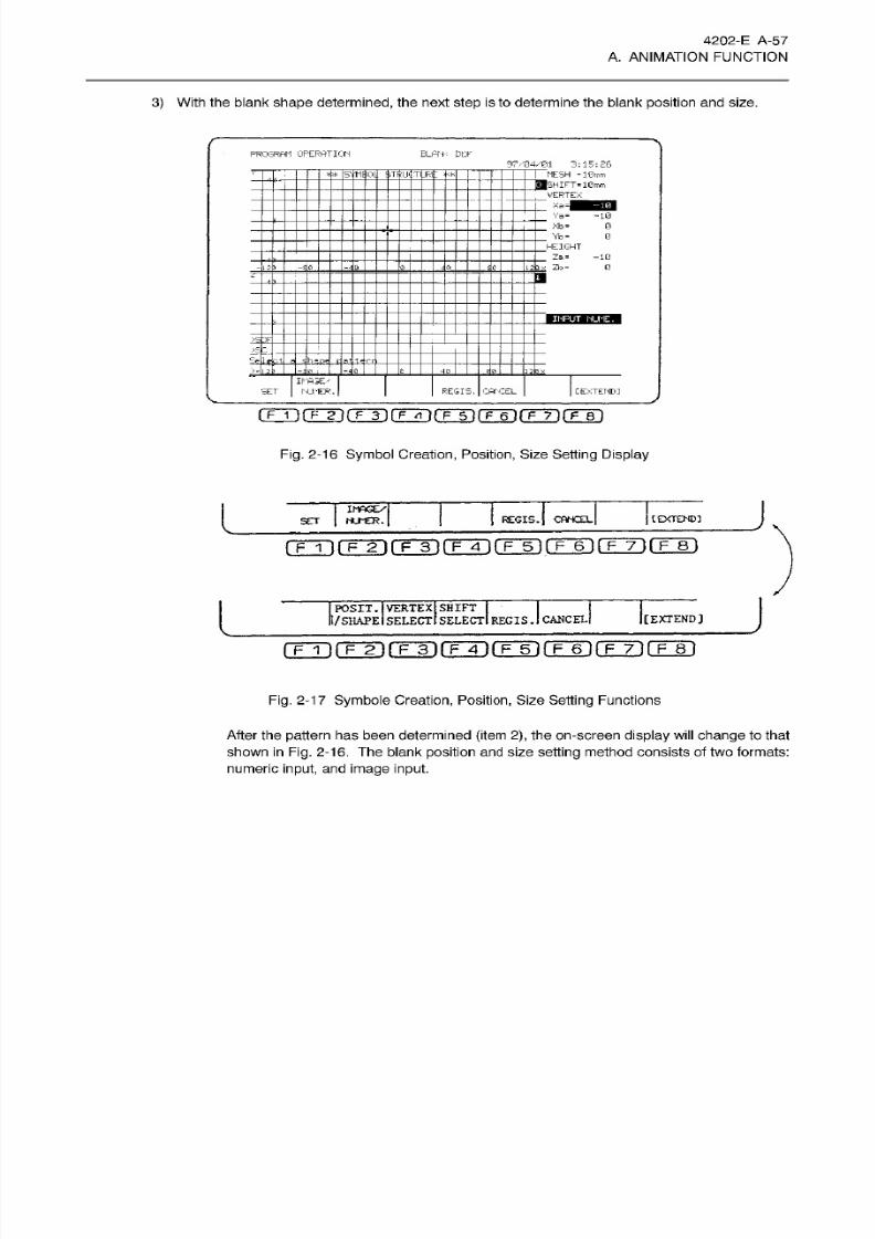
8/15/2019 Okuma Manuals 391
http://slidepdf.com/reader/full/okuma-manuals-391 84/397
4202-E A-57
A. ANIMATION FUNCTION
3) With the blank shape
determined,
the next
step
is to determine the blank position and size.
PROGRPtf
OPERATION
BLPN-:
DEF
97/04/01
3:15:26
|
ME'SH
=
l@mm
__
>HIFT=lGmm
.
VERTEX
__
Xa=|
__
Va= -10
__
Xb =
__
Yb«
__
HEIGHT
__
Za=
-10
2 lx
Zl:i
=
'MflOll
$TRIJ'|:TI
JH
I
*
0
0
0
E<I'r
SE
04 ÿ
IKA3E.T
hUriER
.
REGIS.
CANCEL
[EXTEND]
SET
(TT>(TT]rFT]rFTnrFTirÿ6]rF~7](TT)
Fig.
2-16 Symbol
Creation, Position,
Size Sett ing
Display
J
IMAGE/
KJMER.
[EXTENDI
REGIS.
|
CANC£L|
ET
fFÿnfF~2l[
F
3
i
(~F~4~1
(
F
5
l
pF~6 )
[
F 7
)(
F
8
j
J
OSIT.
VERTEX
SHIFT
I/
SHAPE
SELECT
SELECT
REGIS.
I
CANCEL
[EXTEND]
rrT)(TÿrrrifrT)CFÿrrwirFÿrrm
Fig.
2-17 Symbole Creation,
Position,
Size Setting Functions
After the
pattern
has been determined
(item 2),
the
on-screen
display wi ll change
to that
shown in Fig.
2-16. The
blank
position
and size setting method consists
of
two formats:
numeric
input,
and image
input.
8/15/2019 Okuma Manuals 391
http://slidepdf.com/reader/full/okuma-manuals-391 85/397
4202-E
A-58
A. ANIMATION FUNCTION
(a) Numeric input format
Press
function key [F2]
(IMAGE/NUMBER.)
until INPUT
NAME
is
displayed in
the lower
right
portion
of the
display
shown
in Fig.
2-16.
At
the
right
side of
the
display
shown
in
Fig.
2-14,
there
are coordinate values which
apply
to each
symbol
item. Press
function
ke y
[F1]
(SET),
enter the
numeric
value
and
press
the WRITE key.
This
sets
the
desired coordinate values
which
determine
the
symbol
position
an d
size.
(b)
Image
input
format
Press
the
[F2] (IMAGE/NUMBER.)
function ke y
until
INPUT IMAGE is displayed in the lower
right
portion
of
the
display
shown
in Fig. 2-16.
Image input
consists
of two
modes:
1)
Position
determine
mode
Determines
the
symbol
position.
2) Shape determine mode
Determines the
symbol
size.
(c)
Position determine mode
Press
function ke y [F2]
(POSIT./SHAPE)
shown
in
Fig. 2-17
until
POSITION
is
displayed in
the
lower
right
portion
of the
display
shown
in
Fig.
2-17.
Use
the cursor to move
the
symbol
to the
desired
position.
(d)
Shape
determine mode
Press function
ke y
[F2] (POSIT./SHAPE) shown
in
Fig.
2-1
7 until
SHAPE is
displayed in
the lower
right
portion of
the display
shown
in Fig.
2-16.
The desired shape can be determined
by
using
the
cursor key.
The
page
key
is used for
magnification/reduction.
The blank
symbol
pattern
changes
which
occur by
using
the
page
and
cursor
keys
are
shown
in
Fig.
2-19
to
Fig.
2-21
.
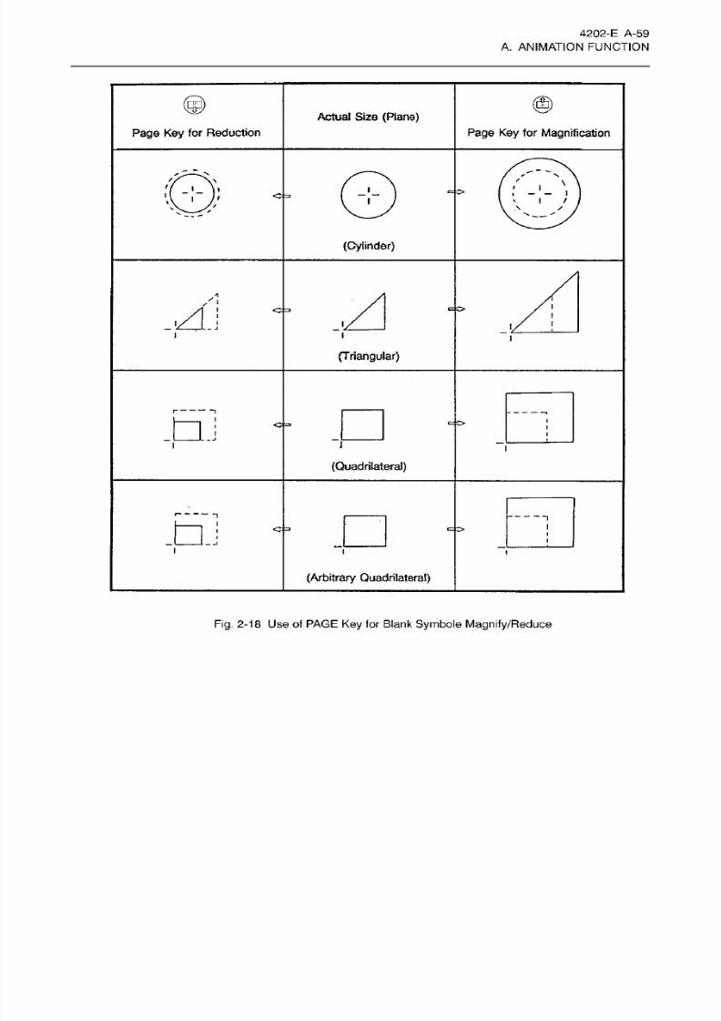
8/15/2019 Okuma Manuals 391
http://slidepdf.com/reader/full/okuma-manuals-391 86/397
4202-E
A-59
A. ANIMATION FUNCTION
Actual
Size
{Plane)
Page
Key
for
Reduction
Page Key
for
Magnification
\
i
i
i
t
I
I
/
\
/
(Cylinder)
s'
.A
i
i
.1
i
i
i
i
(Triangular)
---
-P
Q j
i
i
(Quadrilateral)
---
1
---
dJ
i
i
i
(Arbitrary
Quadrilateral)
Fig.
2-18
Use
of PAGE
Key for
Blank Symbole
Magnify/Reduce
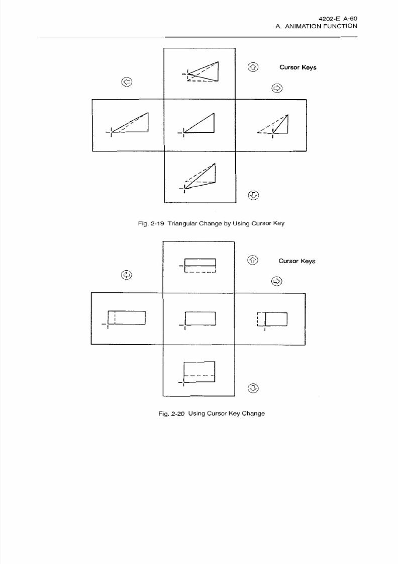
8/15/2019 Okuma Manuals 391
http://slidepdf.com/reader/full/okuma-manuals-391 87/397
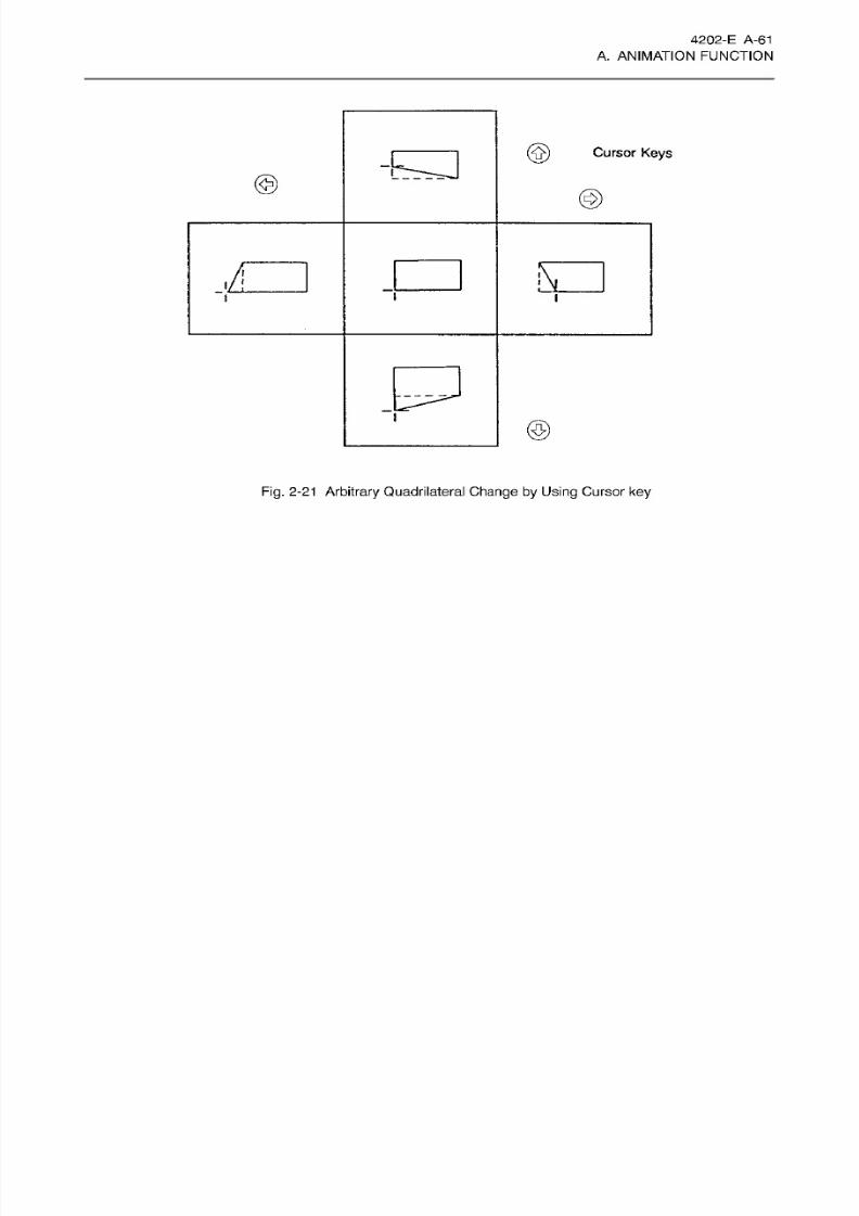
8/15/2019 Okuma Manuals 391
http://slidepdf.com/reader/full/okuma-manuals-391 88/397
4202-E A-61
A. ANIMATION FUNCTION
Cursor Keys
©
©
A
i
©
Fig.
2-21
Arbitrary
Quadrilateral
Change by Using
Cursor
ke y
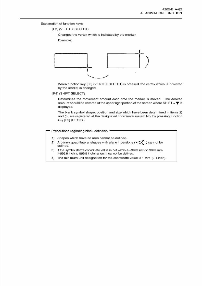
8/15/2019 Okuma Manuals 391
http://slidepdf.com/reader/full/okuma-manuals-391 89/397
4202-E A-62
A. ANIMATION FUNCTION
Explanation of function
keys
[F3]
(VERTEX
SELECT)
Changes the vertex which is indicated
by
the marker.
Example:
When
function
key
[F3]
(VERTEX
SELECT)
is
pressed, the
vertex
which is indicated
by the
market
is
changed.
[F4]
(SHIFT
SELECT)
Determines
the
movement amount
each
time the marker
is
moved.
The
desired
amount
should
be entered
at
the upper
right
portion
of
the screen where SHIFT
=
is
displayed.
The blank
symbol
shape, position
and size which have been determined
in
items
2)
and
3),
are
registered at the designated
coordinate
system
No .
by pressing
function
ke y
[F5] (REGIS.).
—
Precautions regarding blank definition
1
)
Shapes which have no area
cannot
be defined.
2) Arbitrary quadrilateral shapes
with
plane indentions ( )
cannot
be
defined.
3) If the symbol item’s coordinate
value
is
no t
within
a
-9999
mm
to 9999
mm
(-999.9
inch
to 999.9
inch)
range,
it cannot
be defined.
4)
The minimum unit
designation
for the
coordinate value is
1 mm
(0.1
inch).
8/15/2019 Okuma Manuals 391
http://slidepdf.com/reader/full/okuma-manuals-391 90/397
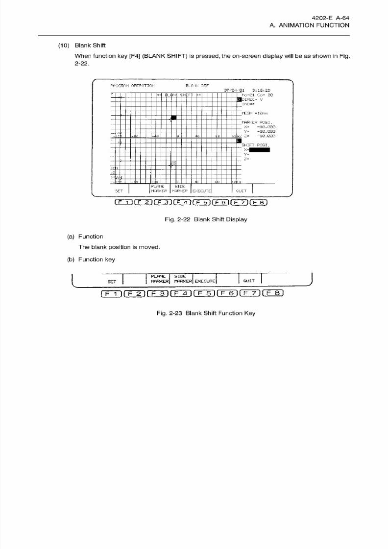
8/15/2019 Okuma Manuals 391
http://slidepdf.com/reader/full/okuma-manuals-391 91/397
4202-E A-64
A. ANIMATION FUNCTION
(10) Blank Shift
When function
ke y
[F4] (BLANK
SFIIFT)
is
pressed, the on-screen
display will
be
as
shown
in Fig.
2-22.
PROGRAM
OPERATION
BLANK DEF
97x34/131 3:
16:25
rn ho
=01
Co*
00
___
DIREC
v
IND«*
IQrr
:r
MESH
=
1
0mm
MARKER POSI.
’
X=
-10.000
.
Y-
-10.000
—10.000
2
Z-
x
SHIFT POSI.
=1
Y=
Z=
’
jl±
I
*Z-
•
PLANE
MARKER
SHE
MARKERET EXECUTE
QUIT
rrrirrTirFTi(TÿrFTirF~6irF~7~)fF~Bi
Fig.
2-22
Blank
Shift Display
(a)
Function
The
blank
position
is moved.
(b )
Function
key
J
PLANE
j
SIDE
j
MARKER
j
MARKER]
EXECUTE
QUIT
SE T
f?~T1
(T~ÿ
f~Fÿ3~)
(~F~4~)
g~F~5~)
(~F~6~I
(
F
7)(~F~8l
Fig.
2-23
Blank Shift
Function Key
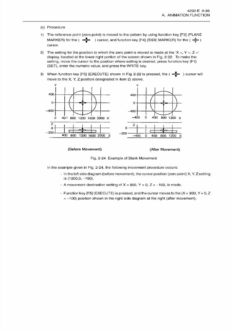
8/15/2019 Okuma Manuals 391
http://slidepdf.com/reader/full/okuma-manuals-391 92/397
4202-E A-65
A. ANIMATION FUNCTION
(c) Procedure
1) The reference
point
(zero point)
is
moved to
the pattern by using
function
ke y
[F3]
(PLANE
MARKER)
for the
(
)
cursor, and
function
key
[F4]
(SIDE MARKER)
for the
( =g= )
cursor.
2)
The setting
for
the
position
to
which
the zero
point
is
moved is made
at
the
‘X
=,
Y
=,
Z
='
display, located at the lower
right
portion of
the screen shown
in Fig.
2-22. To make the
setting,
move the cursor to the
position
where
setting
is desired, press
function
ke y
[F1]
(SET),
enter
the
numeric
value,
an d
press the WRITE key.
3)
When
function ke y [F5]
(EXECUTE)
shown in Fig . 2-22
is
pressed,
the
(
—
) cursor
will
move
to the
X, Y, Z
position
designated
in
item 2)
above.
400
400-
-4
-
0
m
-400-
-400
-400
0
400
800
1
200
X
40 1
800
12 00 1 60 0
2000
X
z
z
0
£
200-
-200
400
800
1200
1600
2000
X
-400
0
400 800
1200
X
(Before
Movement)
(After Movement)
Fig. 2-24
Example of
Blank
Movement
In
the
example
given
in
Fig. 2-24,
the
following movement
procedure
occurs:
-
In
the left
side
diagram
(before
movement)
, the cursor
position (zero point) X,
Y,
Z
setting
is
(1200,0, -100).
-
A
movement destination
setting
of
X
=
800, Y
=
0, Z
= -
100,
is
made.
-
Function
key
[F5]
(EXECUTE) is
pressed,
andthe cursor
moves
to
the (X
=
800,
Y
=
0,
Z
=
-100)
position
shown in the
right
side diagram
at
the
right
(after movement).
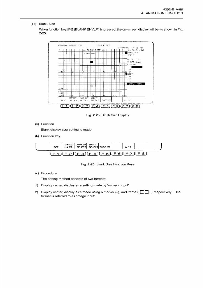
8/15/2019 Okuma Manuals 391
http://slidepdf.com/reader/full/okuma-manuals-391 93/397
4202-E A-66
A. ANIMATION FUNCTION
(11) Blank Size
When function
key
[F5] (BLANK ENVLP.) is pressed, the on-screen
display will
be
as
shown
in
Fig.
2-25.
PROGRAM OPERATION
B LA NK DEF
97/04/01
4:15:49
_
No =01 Co = 00
___
DIREC=
V
____
ND-*
**
BLANK
$IIE
MESH -101mm
j£HIFT«4dot
CEfTTER
=1
Y“
j
i
Z=
1WIDTH
X-
Y-
Z=
INPUT NUME.
_
_
,
S
MARKER SHIFT
SELECT
IMAGE.'
SET
NUMER.
SELECT EcECLTE
Cl
JIT
Fig.
2-25 Blank Size
Display
(a)
Function
Blank display size setting
is made.
(b )
Function
key
J
IMAGE/
MARKER
SHIFT
NJMER.
SELECT
SELECT EXECUTEET
QUIT
rrri(TÿrFÿrrÿrFÿiTÿ(T~7irF~8i
Fig.
2-26
Blank Size
Function Keys
(c)
Procedure
The
setting method
consists
of two formats:
1)
Display
center,
display
size
setting
made
by
‘numeric input’.
2) Display
center, display size
made
using
a marker
(+),
and frame
(
format is referred to as
‘image
input’.
)
respectively.
This
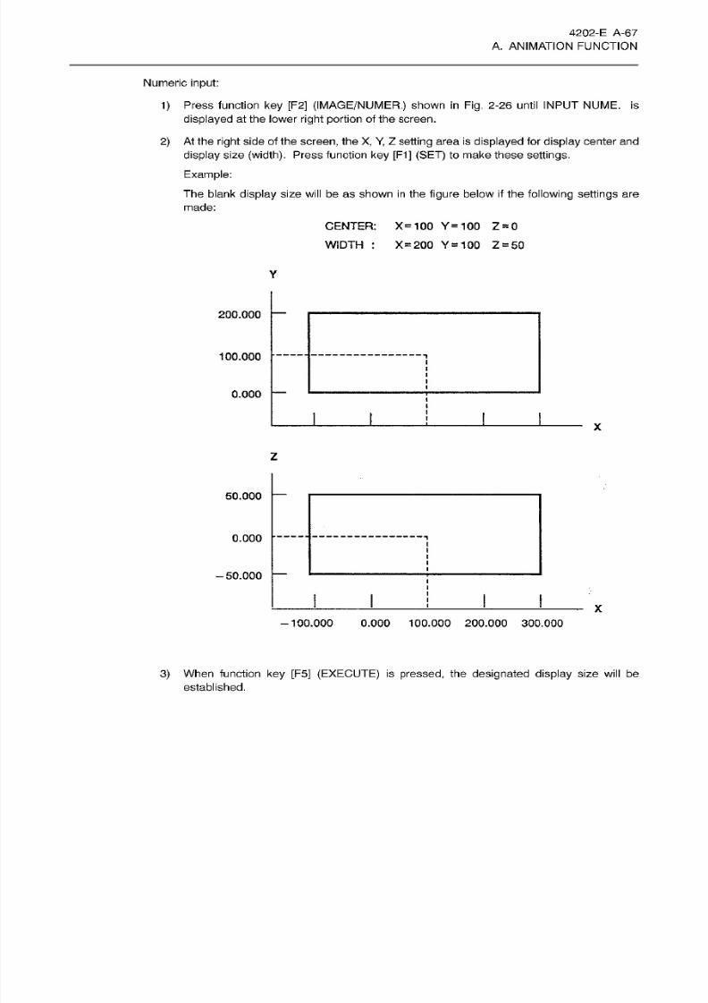
8/15/2019 Okuma Manuals 391
http://slidepdf.com/reader/full/okuma-manuals-391 94/397
4202-E
A-67
A. ANIMATION FUNCTION
Numeric input:
1) Press function
ke y
[F2]
(IMAGE/NUMER.)
shown
in
Fig.
2-26 until INPUT NUME.
is
displayed
at the lower
right
portion
of the
screen.
2)
At the
right
side of the
screen,
the
X, Y,
Z
setting area
is
displayed
for
display
center
and
display
size
(width).
Press function
ke y [F1]
(SET)
to
make these
settings.
Example:
Th e
blank
display
size
will
be
as
shown in the figure below
if
the
following settings
are
made:
CENTER: X=100 Y=100
Z
=
0
WIDTH
: X
=
200
Y
=
10 0
Z
=
50
Y
200.000
100.000
0.000
X
z
50.000
0.000
T
-50.000
X
-100.000
0.000
100.000
200.000
300.000
3)
When function key
[F5]
(EXECUTE)
is
pressed,
the
designated display
size
will
be
established.
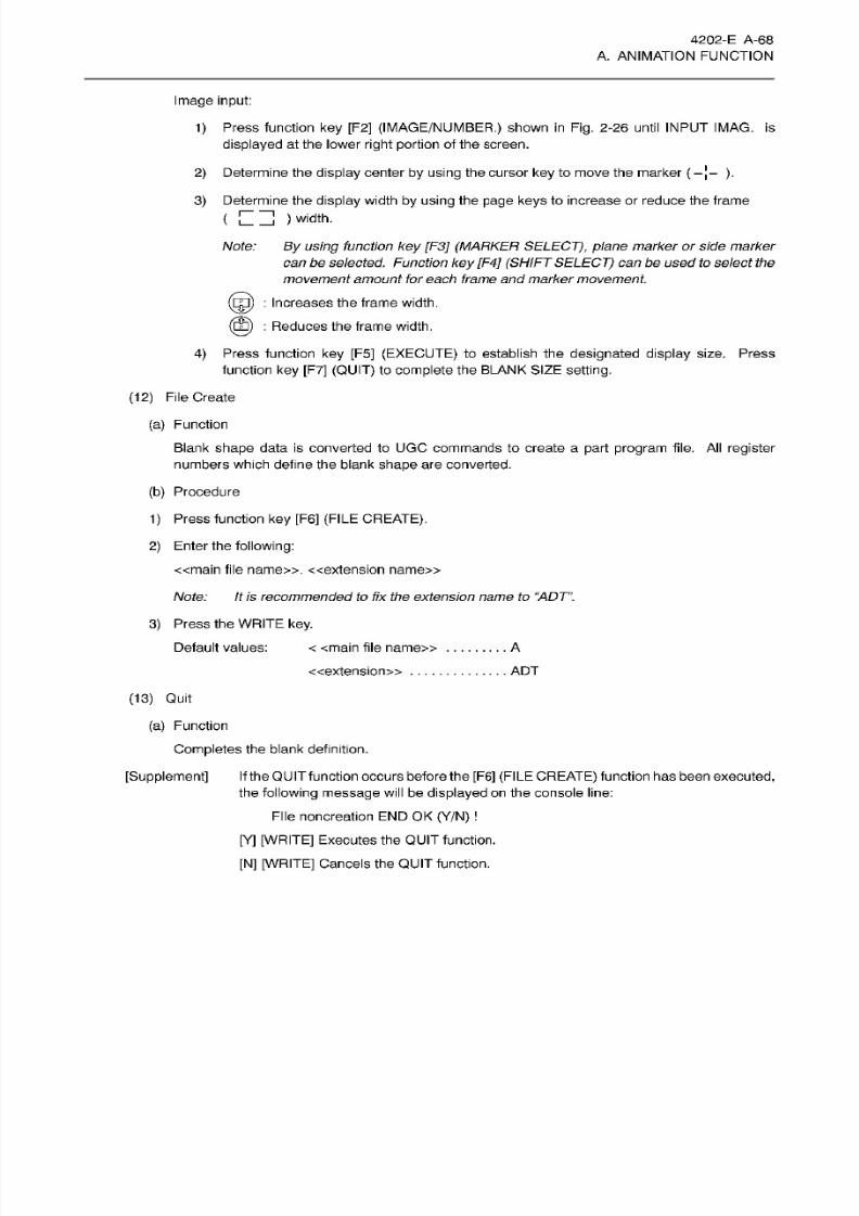
8/15/2019 Okuma Manuals 391
http://slidepdf.com/reader/full/okuma-manuals-391 95/397
4202-E
A-68
A. ANIMATION FUNCTION
Image
input:
1) Press function
ke y
[F2]
(IMAGE/NUMBER.)
shown
in Fig.
2-26
until
INPUT IMAG.
is
displayed
at the lower
right
portion
of the
screen.
2)
Determine
the
display
center
by using
the cursor ke y to
move
the marker
(
-
[- ).
3)
Determine
the
display
width
by using
the
page keys
to
increase or
reduce
the frame
(
) width.
Note:
By
using
function
key
[F3]
(MARKER SELECT),
plane
marker
or side
marker
can
be selected. Function
key
[F4]
(SHIFT SELECT) canbe used
to
select
the
movement
amount fo r each frame
and
marker movement.
©
:
Increases the frame
width.
:
Reduces the frame
width.
4) Press function
key [F5] (EXECUTE)
to establish
the designated
display
size. Press
function
ke y [F7]
(QUIT)
to
complete
the
BLANK
SIZE
setting.
(12)
File
Create
(a) Function
Blank
shape
data is converted to UGC commands to create
a
part
program
file.
Al l register
numbers
which define
the
blank
shape
are
converted.
(b)
Procedure
1)
Press
function
key
[F6]
(FILE CREATE).
2) Enter the
following:
«main
file name». «extension name»
Note:
It is recommended to
fix
the
extension
name
to
“ADT”.
3) Press the
WRITE
key.
Default values:
<
<main
file name» A
ADT
extension»
(13)
Quit
(a)
Function
Completes the blank definition.
[Supplement]
If
the QUIT function occurs before the
[F6]
(FILE CREATE)
function has been
executed,
the
following message
will
be
displayed
on the console l ine:
File noncreation
END
OK
(Y/N)
[Y] [WRITE]
Executes
the
QUIT function.
[N]
[WRITE]
Cancels
the
QUIT function.
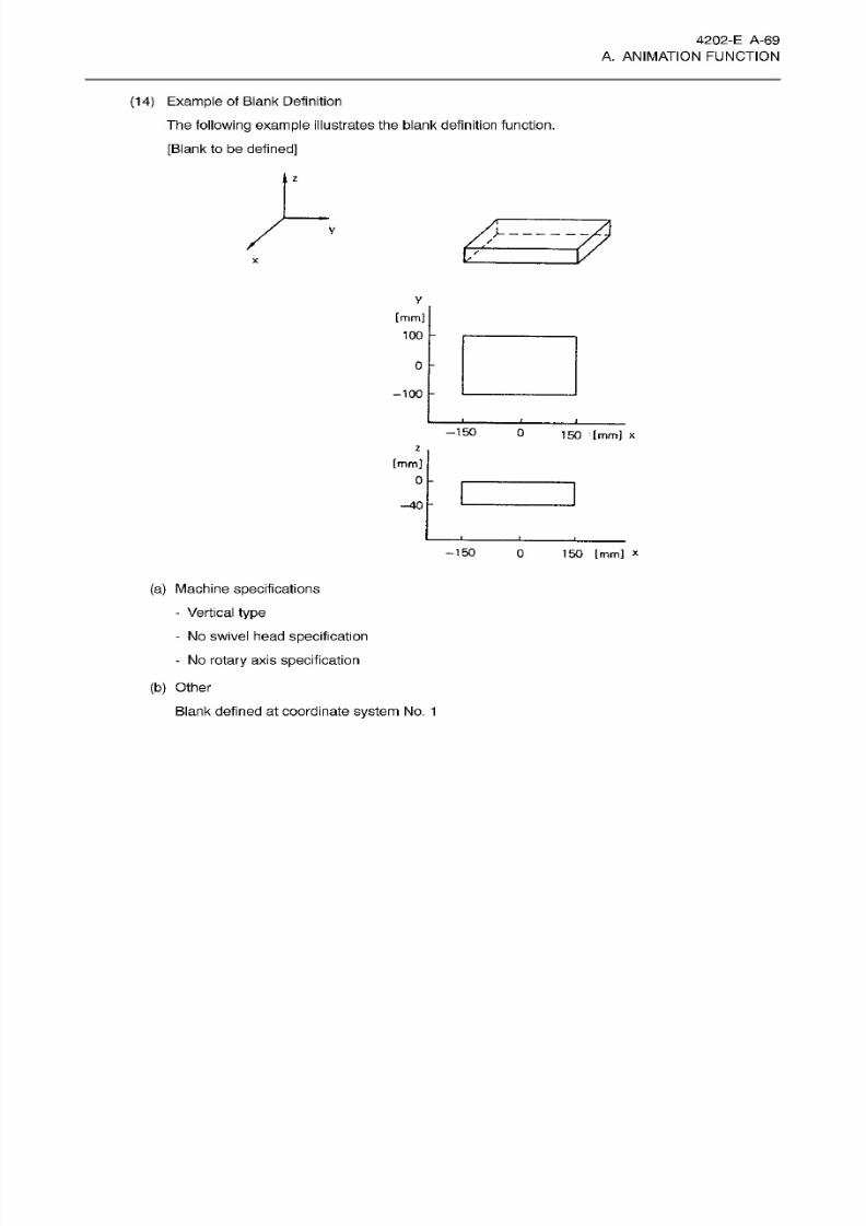
8/15/2019 Okuma Manuals 391
http://slidepdf.com/reader/full/okuma-manuals-391 96/397
4202-E
A-69
A. ANIMATION FUNCTION
(14) Example of B lank
Definition
The
following
example illustrates the blank definition function.
[Blank
to be
defined]
z
y
y
/
X
y
[mm]
10 0
0
-100
-150
0
150
[mm] x
z
[mm]
0
-40
-150
0 150
[mm]
x
(a)
Machine
specifications
- Vertical
type
-
No swivel head
specification
-
No rotary axis specification
(b)
Other
Blank defined at
coordinate
system
No.
1
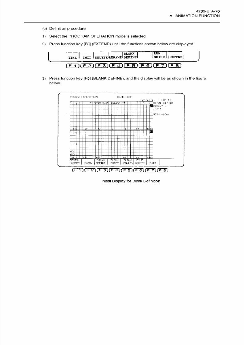
8/15/2019 Okuma Manuals 391
http://slidepdf.com/reader/full/okuma-manuals-391 97/397
4202-E A -70
A.
ANIMATION
FUNCTION
(c) Definition
procedure
1) Select the PROGRAM OPERATION mode
is
selected.
2) Press function
ke y
[F8] (EXTEND)
until the
functions shown below are
displayed.
J
RU N
(BLANK
INIT
I
DELETEIRENAME
I
DEFINE
GUIDE
I
[
EXTEND
]
TIME
rFTirr2irF3irFÿ~)rF~5irF~6irFÿifF~8i
3)
Press function
ke y
[F5]
(BLANK
DEFINE),
and the
display
will be as
shown in the
figure
below.
PR0GRPI1 CFEfMTICN
ELHH-< DEF
97.-04.-31
3:05:11
Ho
=01
Co-
00
I
__
DIREC-
v
IMD=+
V
-H-ft
OPERATION
SELECT
MESH
-10mir
-ilk
-E 0
a.
e_
=3 0
J1
TEF.
£L
REGIS.
HUMBER
SYMBOL
COOR.
BERIME
BLANK
SHIFT
BLANK
ENVLP .
FILE
CREATE
QUIT
(
F
1
)(F
2
|(
F
3)fFTll(
F
5)(T~6lf
F
7)(Tb1
Initial
Display
for
Blank
Definition
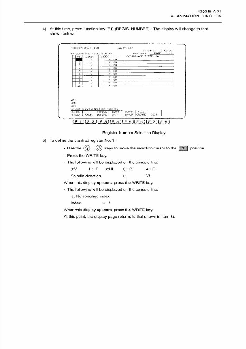
8/15/2019 Okuma Manuals 391
http://slidepdf.com/reader/full/okuma-manuals-391 98/397
4202-E
A-71
A. ANIMATION FUNCTION
4) At this
time, press function ke y [F1]
(REGIS.
NUMBER).
The display will
change
to that
shown
below.
PROGRAM
OPERATION
BLANK
DEF
97K04K01
3:08:55
R-flXIS:
>
F'AGE
1/1
**
BLANK
HO.
SELECTION
**
COORDINATE
SYSTEM Ho.
NDEX
o
. DIREC
so
_
v’
00V
,-lT
V
*
5
V
00
00
_
V
7
00
V_
00
V
00
_
V
00
0
V
-EX
=MB
>EN
Select
r
eg
istra.t
ion
number
SYMBOL BLANK
BLANK
FILE
DEFINE SHIFT
ENVLP.
CREATE
REGIS.
NUMBER
COOR.
QUIT
rrTirrrirFT)(TÿrFTirF~6irF~73fF~r)
Register
Number Selection
Display
5)
To define the blank at
register
No. 1
:
-
Use
the
(ÿ)
, (5)
keys
to
move
the selection cursor to the
|||||
position.
- Press
the
WRITE key.
-
The
following will
be
displayed
on
the console
line:
4:HR
:V
1 :HF
2:HL 3:HB
Spindle direction
When
this
display
appears, press
the WRITE key.
-
The following
will
be displayed on the
console line:
T:
No
specified
index
*
When this
display appears, press
the
WRITE key.
At this
point, the display page
returns to
that shown in
item
3) .
V
:
Index
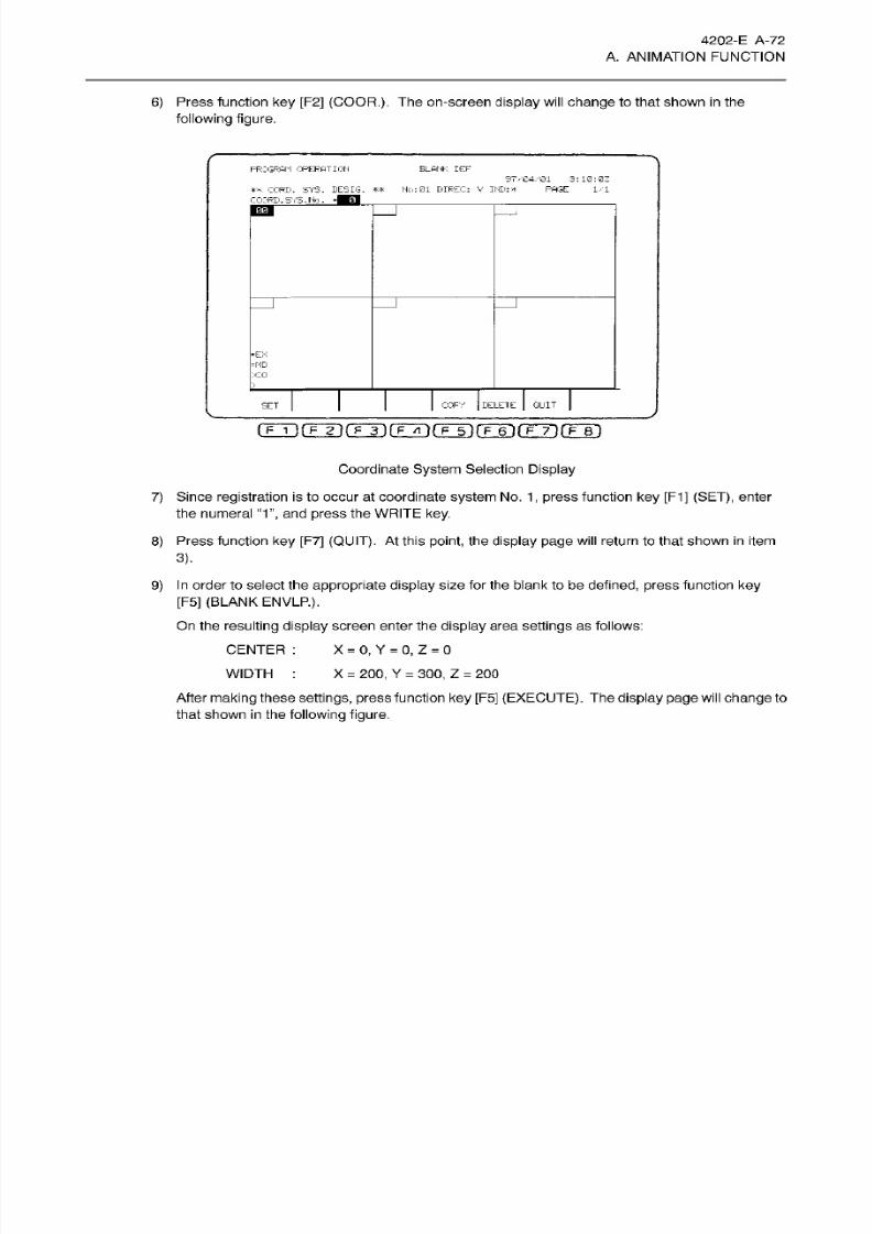
8/15/2019 Okuma Manuals 391
http://slidepdf.com/reader/full/okuma-manuals-391 99/397
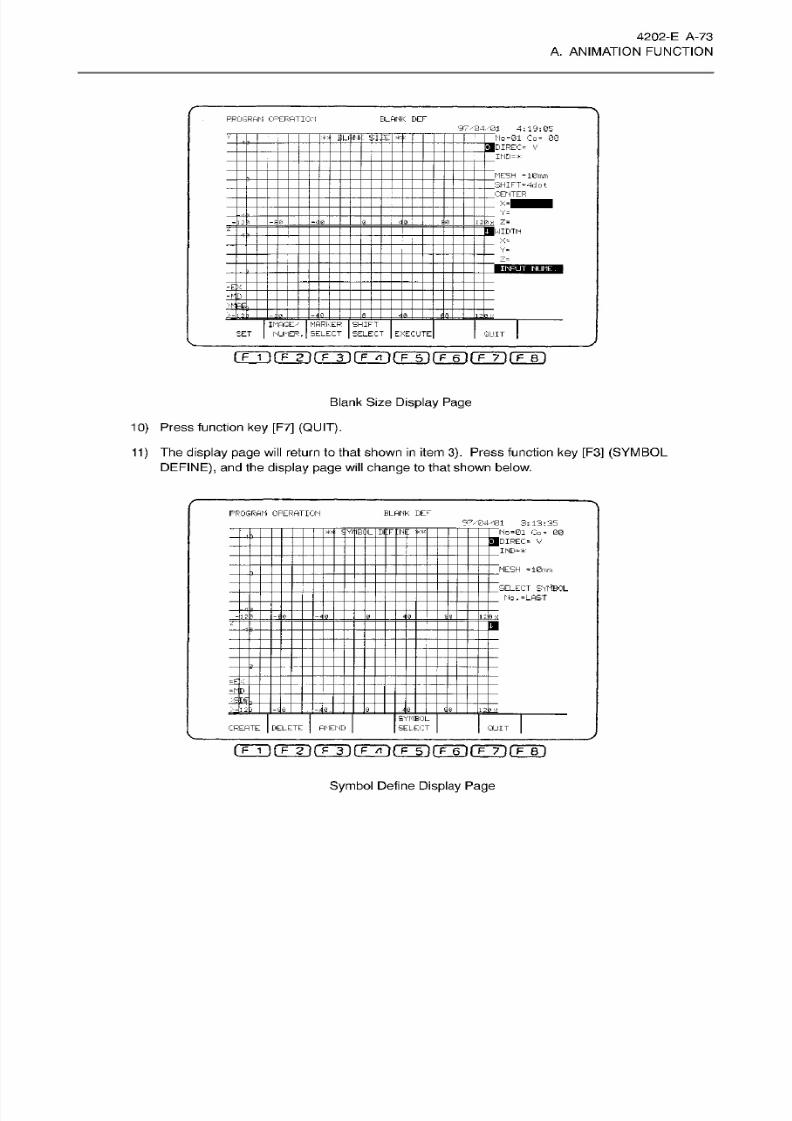
8/15/2019 Okuma Manuals 391
http://slidepdf.com/reader/full/okuma-manuals-391 100/397
4202-E A-73
A. ANIMATION FUNCTION
BLANK
DE F
ROGRAM
OPERATION
97/34/01
4:19:05
:
No -01 Co=
00
__
DIREC-
V
IND-*
i
iLffrNij:
'siiiE
MESH
-10mm
SHIFT-4dot
CENTER
-|
_
V=
Ji
Z*
1NIBTH
X-
V-
z=
INPUT
NUME.
D_
m
IMAGE./
SE T NJMER.
MARKER
SELECT
SHIFT
SELECT
EXECUTE QUIT
(TT>(TTirFTirFGri(TTirÿTirF~7i(TT)
Blank Size
Display Page
10)
Press function
key
[F7]
(QUIT).
11)
The
display
page will
return to that shown
in
item
3).
Press function
ke y [F3]
(SYMBOL
DEFINE),
an d
the
display page
will
change
to that shown below.
PROGRAM
OPERATION
BLANK DE F
97VE4-T31
3:13:35
No-01 Co -
00
___
DIREO
V
____
IHD-*
**
SVitlBJiL
DtFtNE
If*
.MESH
-10mm
’SELECT
SYMBOL
.
No. -LAST
zE
=
M
D_
_
JQ
SYMBOL
SELECT
REATE
|
DELETE
AMEND
QUIT
iTAi(TTirFÿ(TTrirr inrr~6irF~7)(TTri
Symbol
Define
Display Page
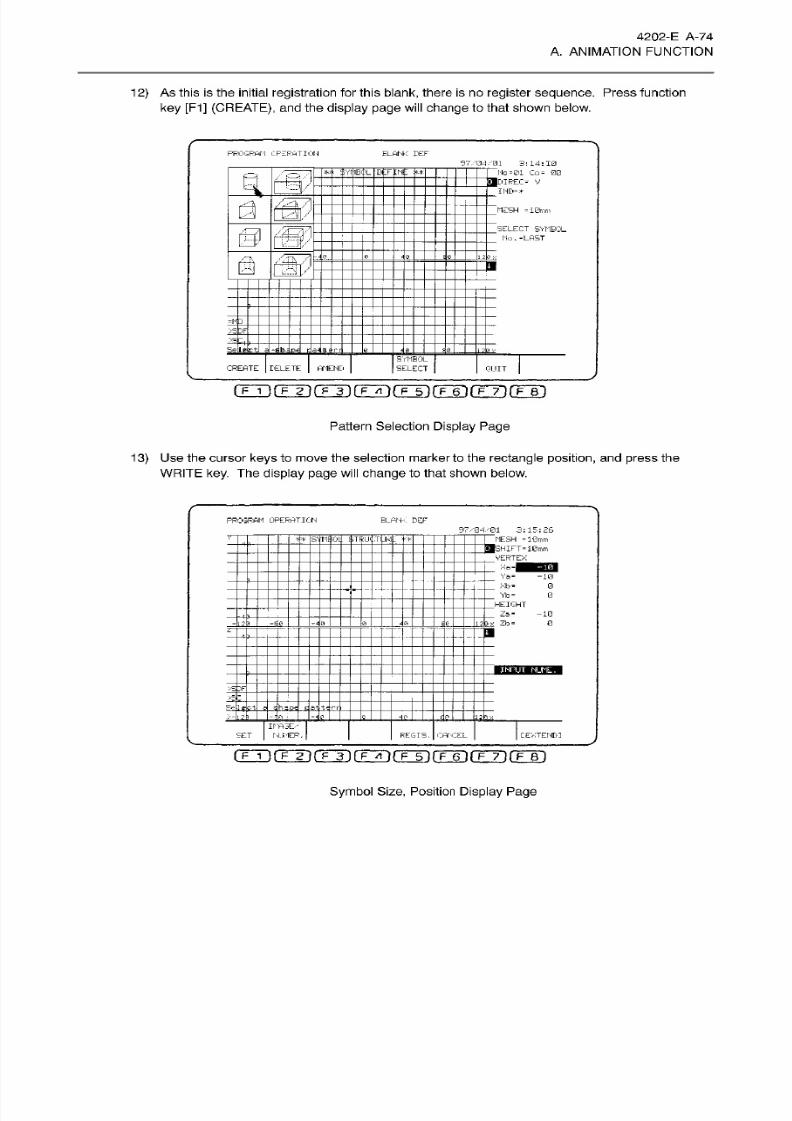
8/15/2019 Okuma Manuals 391
http://slidepdf.com/reader/full/okuma-manuals-391 101/397
4202-E
A-74
A. ANIMATION FUNCTION
1
2)
As this is
the initial
registration
for
this blank,
there
is
no
register
sequence. Press function
ke y [F1]
(CREATE),
and
the
display page
will
change
to
that shown
below.
PROGRAM CPZFHTK'H
ELHNK
DEF
97.
3:14:10
—
FT
No
-01
Co-
00
___
jDIREC- V
IND=»
I
;;vr
iB-;
'L
DfrjNiE
/c=v
a
SP
_MESH
=10rnm
.SELECT
SYMBOL
.
Mo
.=LRST
0
(W
a
a
zt
~
;
-)
hr
SYMBOL
SELECT
REATE
DELETE AMEND
QUIT
rTÿfrÿrÿirÿrÿ5irÿ6~)fFÿi(T~Bi
Pattern
Selection Display Page
13)
Use the
cursor
keys
to
move
the selection marker
to
the
rectangle
position,
and
press
the
WRITE
key. The
display
page
wil l change
to that shown below.
PROGRAM
OPERATION BLGM<
DEF
97 /0 4'0 1 3:1 5:2 6
FT~
MESH
=10mm
__
I
FT
=
10mm
VERTEX
_
INT
x«-|
Ya«
Xb«
-10
0
Yb“ 0
_
HEIGHT
_
Za- -10
jx
Zb-
0
L a
• L
,
..
a
>S0F
h
=
pe
.t*
rt
ir-flSE/
NJMER,
ET
REGIS. CANCEL
C
EXTEND]
nmrrÿrÿrFTÿrr5)rÿ6~)rrT)rF~Bi
Symbol Size,
Position
Display
Page
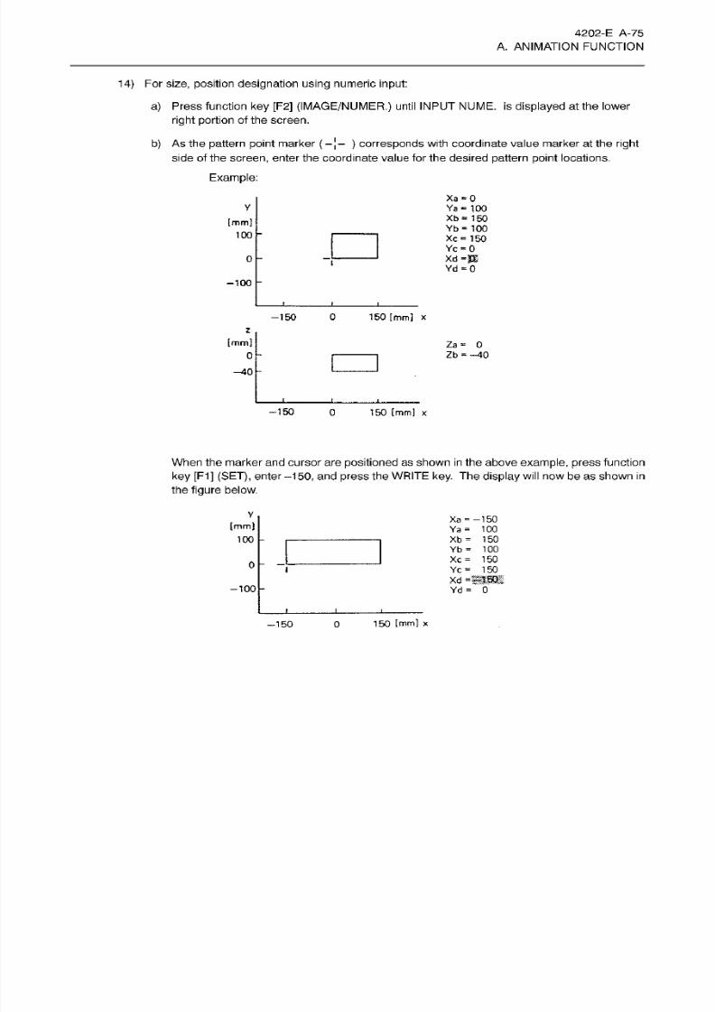
8/15/2019 Okuma Manuals 391
http://slidepdf.com/reader/full/okuma-manuals-391 102/397
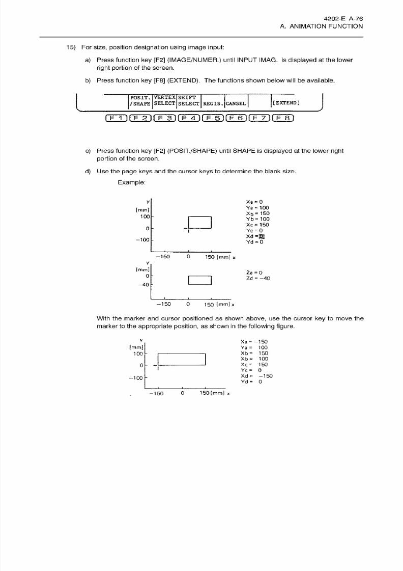
8/15/2019 Okuma Manuals 391
http://slidepdf.com/reader/full/okuma-manuals-391 103/397
4202-E A-76
A. ANIMATION FUNCTION
15) For
size,
position
designation
using image
input:
a) Press function
ke y
[F2]
(IMAGE/NUMER.)
until INPUT IMAG. is
displayed
at the lower
right
portion
of
the screen.
b) Press function
ke y
[F8]
(EXTEND).
The functions shown below
will
be available.
I
J
OSIT.
VERTEX
SHIFT
/SHAPE
SELECT
SELECT
REGIS.
CANSEL
[EXTEND]
c)
Press
function
key
[F2]
(POSIT./SHAPE)
until
SHAPE
is
displayed
at
the
lower
right
portion
of the screen.
d)
Use
the
page keys and
the cursor
keys
to determine
the
blank
size.
Example:
Xa~0
Ya
=
100
y
(mm]
Xb
=
150
Yb= 100
Xc =
150
Yc
=
0
100
0
xd
-m
-100
Yd
-
0
-150
0
150
[mm]
x
[mm]
2a
=
0
Zd
=
—40
150
[mm]
x
150 0
With the
marker
and cursor
positioned
as shown above,
us e
the
cursor
key
to
move the
marker
to the
appropriate position,
as shown
in
the
following
figure.
Xa
• =
—150
Ya
=
100
Xb
=
150
Xb
= 100
Xc
=
150
Yc
=
0
Xd
=
-150
Yd
= 0
[mm]
100
0
-100
150
[mm]
x
150
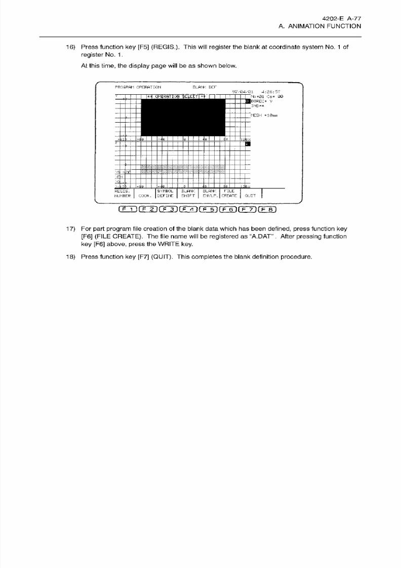
8/15/2019 Okuma Manuals 391
http://slidepdf.com/reader/full/okuma-manuals-391 104/397
4202-E
A-77
A. ANIMATION FUNCTION
16) Press function
key [F5]
(REGIS.).
This will
register
the blank at coordinate
system
No. 1
of
register
No. 1 .
At
this
time,
the
display
page will
be
as
shown below.
B LA NK B EF
ROGRflM
OPERATION
97/04/01
4:26:
5f
No
=01 Co-
00
___
|DIRD;=
v
____
ND-*
CrffFt
I
ESI
j- t
.MESH
-10mm
.
Si
'.
1
E_ANK
SHIFT
SYMBOL
DEFINE
BLANK
ENVLP.
FILE
CREATE
REGIS,
HUMBER COOF.
QUIT
rrrirrTirFTi(TÿrFTirF~6irF~y)fF~Bi
1
7)
For
part program
file creation of the blank
data
which has been
defined,
press function
ke y
[F6] (FILE
CREATE).
The file
name will
be
registered as “A.DAT”
.
After
pressing function
ke y [F6]
above,
press the WRITE
key.
18) Press function
key
[F7]
(QUIT).
This completes
the
blank
definition
procedure.
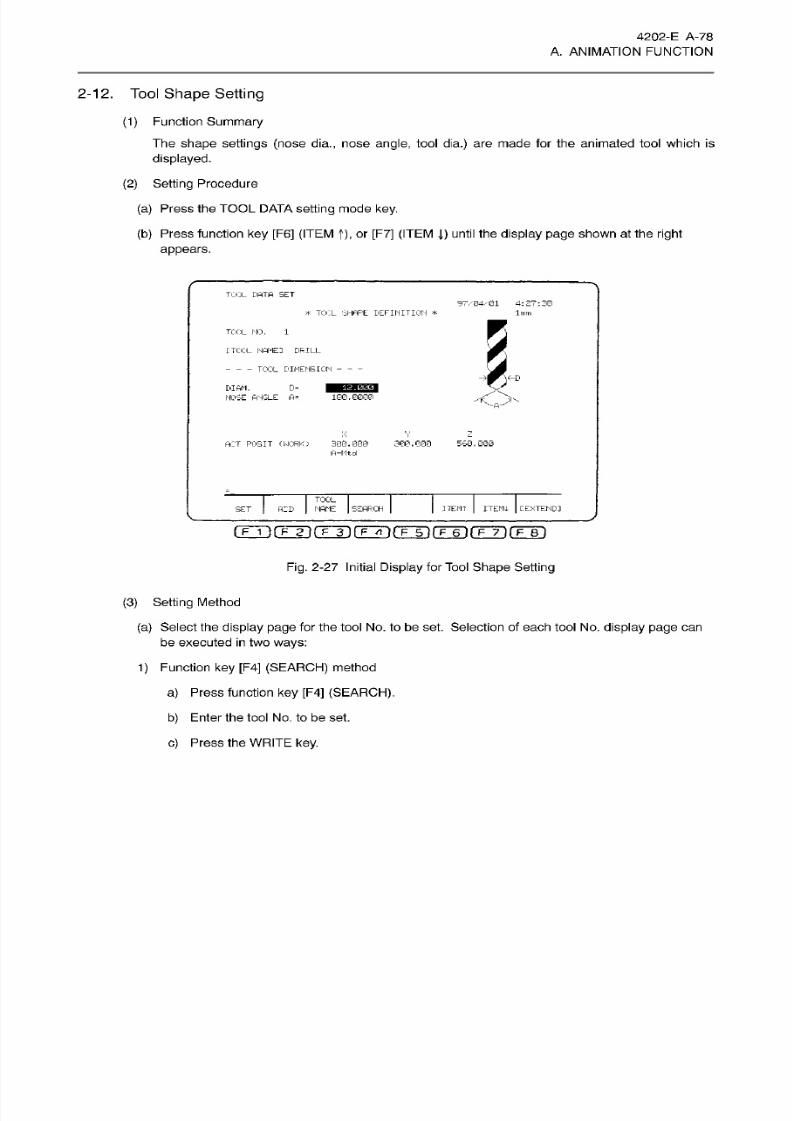
8/15/2019 Okuma Manuals 391
http://slidepdf.com/reader/full/okuma-manuals-391 105/397
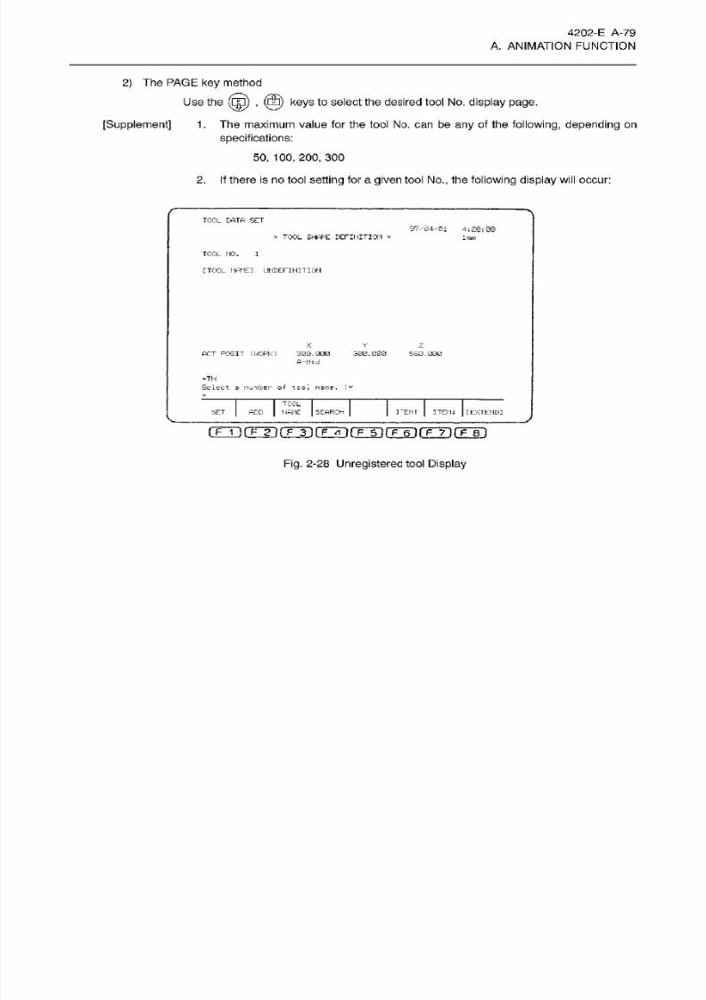
8/15/2019 Okuma Manuals 391
http://slidepdf.com/reader/full/okuma-manuals-391 106/397
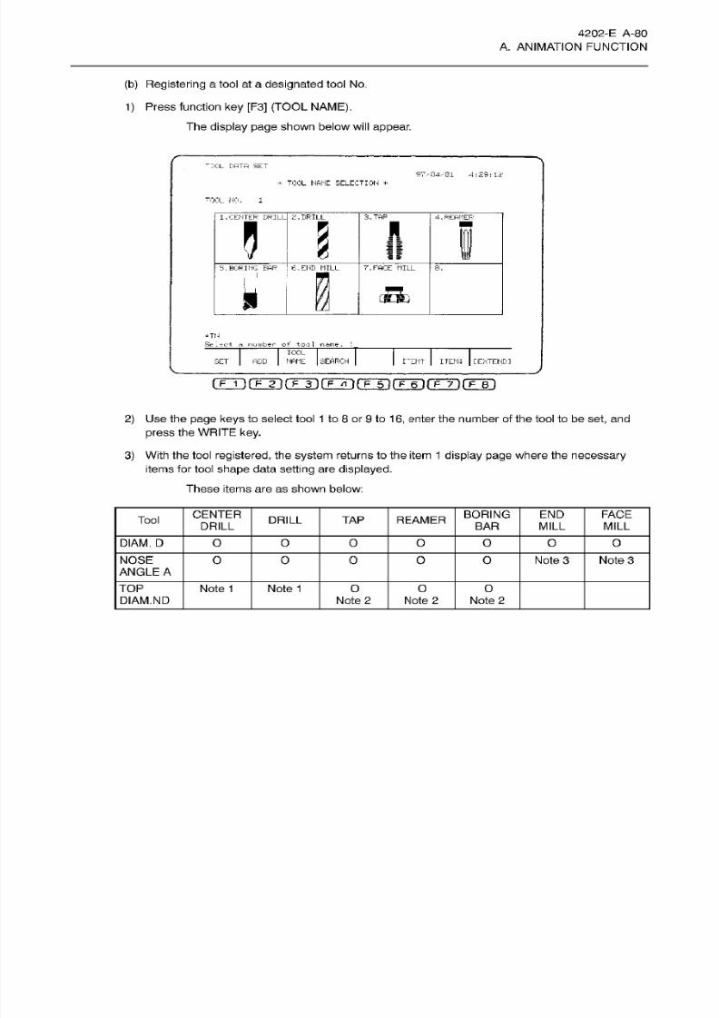
8/15/2019 Okuma Manuals 391
http://slidepdf.com/reader/full/okuma-manuals-391 107/397
4202-E
A-80
A.
ANIMATION
FUNCTION
(b)
Registering
a tool at a
designated
tool No.
1)
Press function
ke y
[F3]
(TOOL NAME).
The
display page
shown below
will
appear.
DOL DATA
SET
S7V04/-01 4:29:12
*
TOOL
NAME
SELECTION
*
TOOL
NO. 1
1.
CENTER
DRILL 2. DRILL 3.
TAP
4.
REAMER
5
H
®
t
6. END MILL
.
BORING BAR 7. FACE MILL 8.
I
5
-TN
Select a number of tool name.
TOOL
ADD MANE SEARCH
IÿEMT
ITEMI
[EXTENDI
ET
(F
1
Ifmif
3
)
\~F~A
}
rF~5~l
TF~6T fF~7T
fF~ET)
2)
Use the
page keys
to select tool
1
to
8
or
9
to
16,
enter
the number
of
the tool to be
set,
and
press
the
WRITE
key.
3)
With the tool
registered,
the
system
returns to the
item
1
display page
where
the
necessary
items
for
tool
shape
data
setting are
displayed.
These items
are as
shown
below:
CENTER
DRILL
BORING FACE
ND
Tool
DRILL TA P REAMER
BAR
MILL MILL
D IAM. D
O O O O O O 0
NOSE
ANGLE
A
O
0
O O
O Note 3 Note
3
TOP
Note 1
Note
1
O O O
DIAM.ND
Note 2 Note 2 Note
2

8/15/2019 Okuma Manuals 391
http://slidepdf.com/reader/full/okuma-manuals-391 108/397
4202-E A-81
A. ANIMATION FUNCTION
[Supplement]
Fo r center drill and
dril l, ND
=
0.
.
If nose angle sett ing
is
A
=
180
degrees,
this data
will
not be referenced.
Fo r
end mill and fflce
mill,
nose
angle sett ing
is
A
=
180
degrees.
The permissible
input
at
this time
is as
follows:
numeric
character
(1
-
16),
an
asterisk
(>i<)
or
the
WRITE
key.
If
a
numeric
character (1 -
16 )
is
entered for a
too l which is no t
displayed,
an
error
will
occur,
and
input
will be impossible.
If
an
asterisk
(T)
is
entered, a
“tool
no t registered’’
undefinition status is
established
at the
tool
number
which was
designated.
If the
WRITE
key is
pressed,
the tool
which is
registered
at
the designated tool
number will
remain as
is, and the display
page
will
return
to
that w hic h w as
displayed before
function
key [F3] (TOOL NAME)
was
pressed.
2.
3.
4.
5.
6.
7.
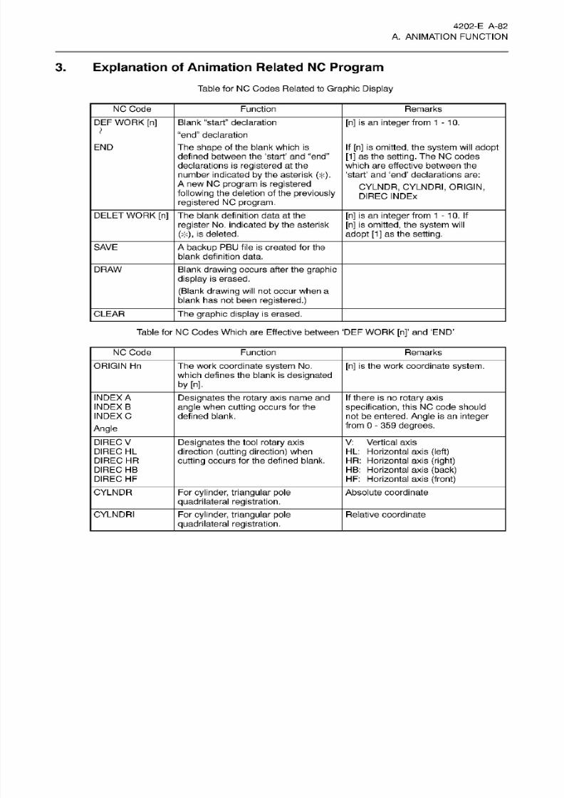
8/15/2019 Okuma Manuals 391
http://slidepdf.com/reader/full/okuma-manuals-391 109/397
4202-E A-82
A. ANIMATION FUNCTION
3.
Explanation of
Animation
Related NC
Program
Table for
NC Codes Related to
Graphic
Display
NC Code Function
Remarks
DEF WORK
[n ] Blank
“start”
declaration
“end” declaration
The
shape
of the blank which is
defined
between
the
‘start’
an d
“end”
declarations is
registered
at
the
number indicated
by
the asterisk
(T).
A
new
NC
program
is registered
following the
deletion of
the previously
registered
NC
program.
[n ]
is an
integer
from
1-10.
)
If
[n] is
omitted,
the
system
will
adopt
[1]
as the
setting. The
NC codes
which are effective between
the
‘start’
an d ‘end’ declarations are:
CYLNDR,
CYLNDRI, ORIGIN,
DIREC
INDEX
END
DELET
WORK
[n ]
The blank
definition
data
at the
register
No. indicated
by
the
asterisk
(A)
,
is
deleted.
[n ]
is
an integer
from 1
-
10.
If
[n]
is omitted,
the
system will
adopt [1]
as
the
setting.
SAVE A
backup PBU file
is
created
for
the
blank definition
data.
DRAW Blank
drawing occurs
after the
graphic
display
is erased.
(Blank
drawing
will
not occur when a
blank has not been
registered.)
CLEAR
The graphic display
is
erased.
Table for NC Codes
Which
are Effective between
‘DEF
WORK
[n]’
an d
‘END’
NC Code
Function Remarks
ORIGIN
Hn The
work
coordinate
system
No.
which defines the blank is
designated
by [n],
[n ]
is the work coordinate
system.
INDEX
A
INDEX B
INDEX
C
Angle
Designates
the
rotary
axis name
an d
angle when
cutting occurs for the
defined blank.
If
there is no
rotary
axis
specification,
this
NC
code should
not be entered.
Angle
is
an integer
from 0
-
359
degrees.
DIREC
V
DIREC
HL
DIREC
HR
DIREC
HB
DIREC
HF
Designates
the tool
rotary
axis
direction
(cutting
direction)
when
cutting occurs
for
the defined
blank.
V:
Vertical
axis
HL: Horizontal axis
(left)
HR :
Horizontal axis
(right)
HB:
Horizontal
axis
(back)
HF: Horizontal
axis
(front)
CYLNDR
For cylinder,
triangular
pole
quadrilateral
registration.
Absolute coordinate
CYLNDRI For
cylinder,
triangular pole
quadrilateral registration.
Relative
coordinate

8/15/2019 Okuma Manuals 391
http://slidepdf.com/reader/full/okuma-manuals-391 110/397
4202-E A-83
A. ANIMATION FUNCTION
(1)
DEF
WORK [n] -
END
[Format]
[Explanation]
DEF
WORK [n ]
-
END, 1
2
n 1
0
The blank
shape
is
registered.
Between the
start
(DEF WORK[n])
declaration
and
the
“END”
declaration,
the
appropriate shape
command string
and
procedure
statement
(refer
to
the
INDEX, DIREC
items
in
the
following pages)
are
registered.
A cylindrical
blank
will be registered as fol lows:
When
registering
a
cylindrical
blank
of
the
bottom center
(250, 0),
bottom
diameter (226),
bottom
height
(0)
andtopface height (81)
with
cutting
direction
(V)
and no
rotary
axis
spec,
at
register
No.
1
,
the
data
input
is a s follows:
DEF
WORK[1]
DIRECV
ORIGINH1
CYLNDR
OP,
[250,0],
226,0,
81
END
(1):
Blank definition “start”
declaration
(2):
Register procedure
statement
(3):
Shape
command
string
(4):
Shape command
string
(5):
“end” declaration
The coordinate
system
which
is
used when blank definition
occurs,
is thatwhich is used
for the NO
program.
The unit is fixed at
1 mm
(0.1
inch).
A
total of 32
blanks
can be
registered
for CYLNDR
and
CYLNDRI
(combined).
A
total of
32
blanks
can be
registered
for ORIGIN.
(2)
CYLNDR and CYLNDRI
These coordinates
vary according
to the
spindle
direction.
Henceforth,
all
explanations
will assume
a
spindle
direction
setting
of
(V:
vertical
axis).
The
coordinates for
the
other
settings
are
as
follows:
HL
(horiz.
left)
HR (horiz. right)
HF (horiz. front)
HB
(horiz.
back)
Example:
Blank
shape command;
CYLNDR
OP
[-250, 0],
226, 0,
81
.
. Cylinder
[Example]
(1)
(2)
(3 )
(4 )
(5)
[Supplement]
XÿZ,
Y-*X,
Z-»Y
XÿZ,
Y-*X,
Z-»Y
X-*Y,
Y-»Z,
Z ÿX
X-*Y,
Y-»Z,
Z ÿX
Top,
bottom
heights
Dia.
Center
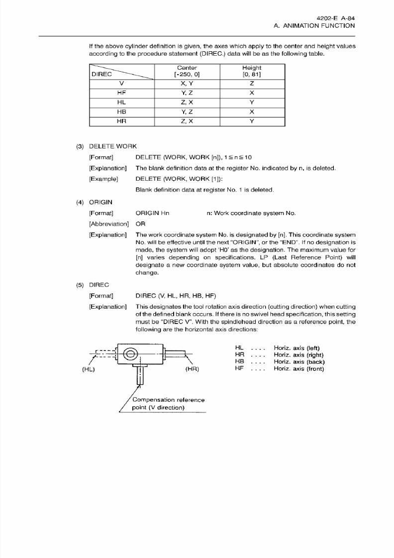
8/15/2019 Okuma Manuals 391
http://slidepdf.com/reader/full/okuma-manuals-391 111/397
4202-E A-84
A. ANIMATION FUNCTION
If
the above
cylinder definition is given, the axes
which
apply
to the center and
height
values
according
to
the
procedure
statement
(DIREC.)
data will be as
the
following
table.
Center
[-250, 0]
Height
[0, 81]
IREC
V X, Y
Z
HF
Y,Z X
HL
Z,X
Y
HB
Y, Z X
HR Z,X
Y
(3)
DELETE
WORK
[Format]
DELETE (WORK,
WORK
[n]), 1 n 1
0
[Explanation]
The blank
definition
data
at the
register
No. indicated
by n,
is
deleted.
[Example] DELETE (WORK,
WORK
[1]):
Blank definition
data
at
register
No.
1
is deleted.
(4)
ORIGIN
[Format]
[Abbreviation]
OR
[Explanation]
The
work
coordinate
system
No . is
designated by
[n].
This coordinate
system
No.
will
be effective until the
next
“ORIGIN”,
or
the
“END”. If
no
designation
is
made,
the
system
will
adopt
‘HO’
as
the
designation.
The
maximum
value
for
[n]
varies depending
on specifications.
LP
(Last
Reference
Point)
will
designate
a
new coordinate
system
value, but absolute
coordinates
do
not
change.
ORIGIN
Hn
n:
Work coordinate
system
No.
(5)
DIREC
[Format]
DIREC (V, HL ,
HR, HB,
HF)
[Explanation]
This
designates the
tool rotation
axis
direction
(cutting direction)
when
cutting
of the
defined blank occurs.
If
there
is
no
swivel head
specification,
this setting
must
be “DIREC V”. With the spindlehead direction as
a
reference point, the
following
are the horizontal axis directions:
HL
....
Horiz. axis
(left)
HR . . .
HB
...
HF
....
Horiz.
axis
(front)
0
~
Horiz.
axis
(right)
Horiz.
axis
(back)
(HR)
HL)
Compensation
reference
point
(V
direction)
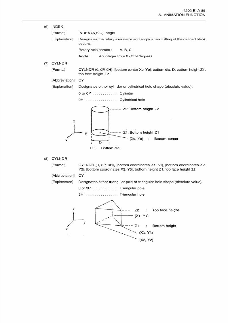
8/15/2019 Okuma Manuals 391
http://slidepdf.com/reader/full/okuma-manuals-391 112/397
4202-E A-85
A. ANIMATION FUNCTION
(6)
INDEX
[Format]
[Explanation]
Designates
the
rotary
axis
name and angle
when
cutting
of the defined blank
occurs.
Rotary
axis
names
:
A , B ,
C
Angle
: An
integer
from
0
-
359
degrees
INDEX
(A,B,C),
angle
(7)
CYLNDR
[Format]
CYLNDR (0,
OP,
OH),
[bottom
center
Xc ,
Yc],
bottom
dia. D,
bottom
height Z1
,
top
face
height
Z2
[Abbreviation]
CY
[Explanation]
Designates either
cylinder
or cylindrical hole
shape (absolute
value).
0 or
OP
Cylinder
Cylindrical hole
H
—
Z2:
Bottom height
Z2
z
--
Z1:
Bottom
height Z1
(Xc,
Yc) :
Bottom center
x.
y
i
x
D
D :
Bottom
dia.
(8) CYLNDR
[Format]
CYLNDR
(3,
3P,
3H),
[bottom
coordinates
X1 ,
VI], [bottom
coordinates X2,
Y2],
[bottom
coordinates
X3 ,
Y3],
bottom height Z1 ,
top face
height 22
[Abbreviation] CY
[Explanation]
Designates
either triangular pole or triangular hole shape (absolute
value).
Triangular
pole
Triangular
hole
3 or 3P
3H
i
z
-
-
Z2
:
To p
face
height
—
(XI,
Y1 )
I
A~
\
y
\
- -
Z1 :
Bottom
height
(X3, Y3)
x
(X2,
Y2)
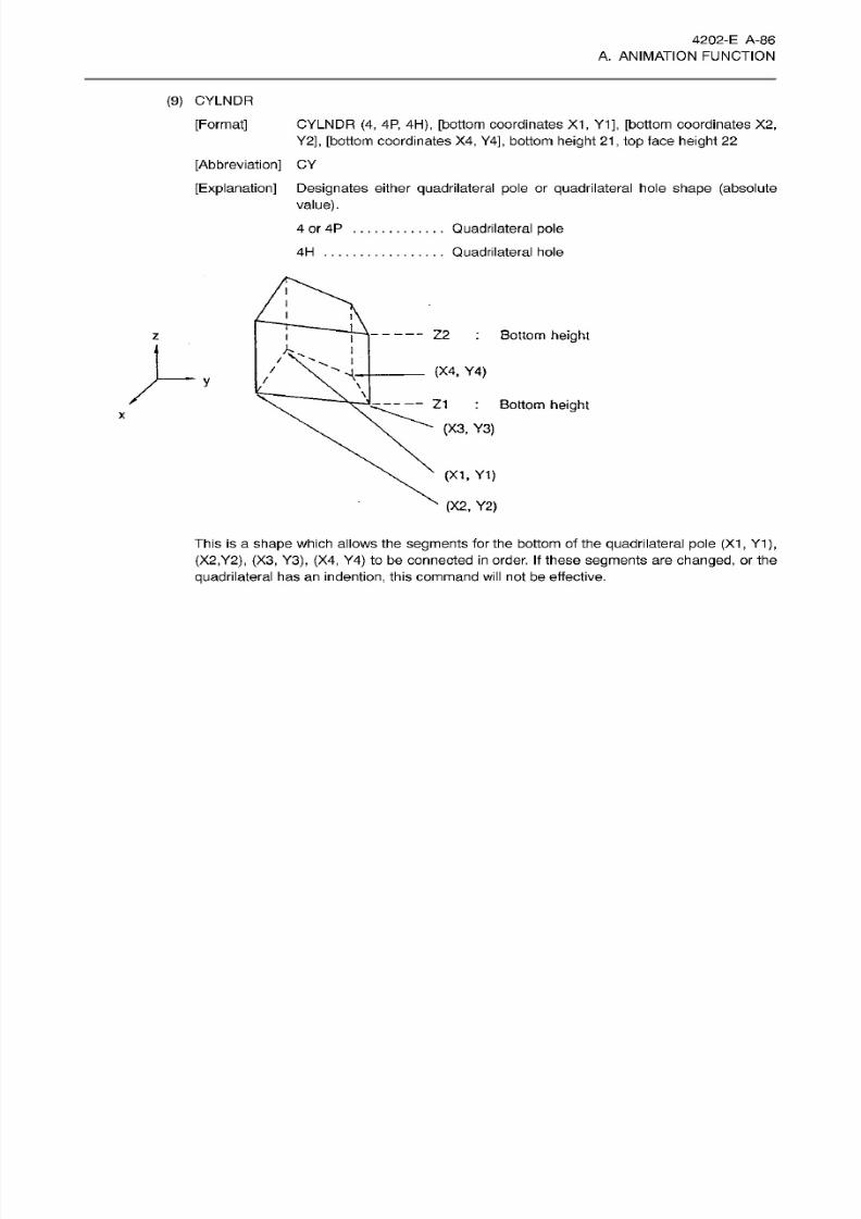
8/15/2019 Okuma Manuals 391
http://slidepdf.com/reader/full/okuma-manuals-391 113/397
4202-E A-86
A. ANIMATION FUNCTION
(9)
CYLNDR
[Format]
CYLNDR
(4 ,
4P,
4H),
[bottom
coordinates
X1,
Y1], [bottom coordinates
X2,
Y2], [bottom
coordinates
X4,
Y4],
bottom
height
21
,
top
face
height
22
[Abbreviation] CY
[Explanation] Designates
either
quadri lateral pole
or
quadrilateral
hole
shape
(absolute
value).
4
or 4P
Quadrilateral
pole
Quadrilateral
hole
H
i
i
l
i
Z2 :
Bottom
height
i
/
/
(X4, Y4 )
M-
\
/
\
Z1
:
Bottom
height
(X3,
Y3)
x
(XI,
Y1)
(X2,
Y2)
This
is
a shape
which
allows the
segments
for
the
bottom of
the
quadrilateral pole (X1,
Y1
),
(X2,Y2), (X3,
Y3),
(X4,
Y4 )
to be
connected
in
order. If
these
segments are changed,
or
the
quadrilateral
has an
indention,
this command will
not
be
effective.
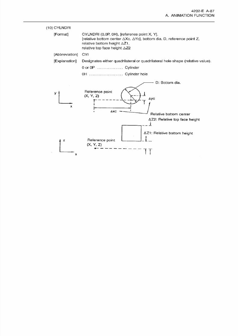
8/15/2019 Okuma Manuals 391
http://slidepdf.com/reader/full/okuma-manuals-391 114/397
4202-E
A-87
A. ANIMATION FUNCTION
(10)
CYLNDRI
[Format] CYLNDRI (0,0P, OH), [reference
point X,
Y],
[relative bottom center
AXc,
AYc],
bottom dia.
D, reference
point
Z,
relative bottom
height AZ1
,
relative
top
face
height AZ2
[Abbreviation]
CYI
[Explanation]
Designates either
quadrilateral
or
quadrilateral
hole
shape (relative value).
Cylinder
Cylinder
hole
Oor OP
OH
D:
Bottom
dia.
Reference
point
(X ,
Y, Z)
-U
Aye
P
r
T
X
I
AXC
Relative
bottom
center
AZ2:
Relative
top
face
height
__1
AZ1:
Relative
bottom
height
Reference
point
(X,
Y,
Z)
z
IT
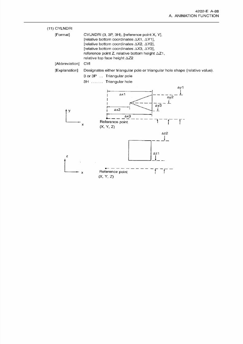
8/15/2019 Okuma Manuals 391
http://slidepdf.com/reader/full/okuma-manuals-391 115/397
4202-E
A-88
A. ANIMATION FUNCTION
(11)
CYLNDRI
[Format]
CYLNDRI
(3,
3P,
3H), [reference point
X,
Y],
[relative
bottom coordinates
AX1
,
AY1],
[relative
bottom coordinates
AX2,
AY2],
[relative bottom coordinates
AX3,
AY3],
reference
point
Z,
relative bottom
height
AZ1
,
relative
top
face
height AZ2
[Abbreviation]
CYI
[Explanation]
Designates
either
triangular pole
or
t riangular hole shape
(relative
value).
3
or
3P
. .
Triangular
pole
Triangular
hole
H
Ay1
1x1
Ay2
1
Ay 3
i
x2
y
AX3
“1
r
eference
point
(X,
Y.
Z)
AZ2
__J_
Az1
z
FT
eference point
(X,
Y,
Z)
x
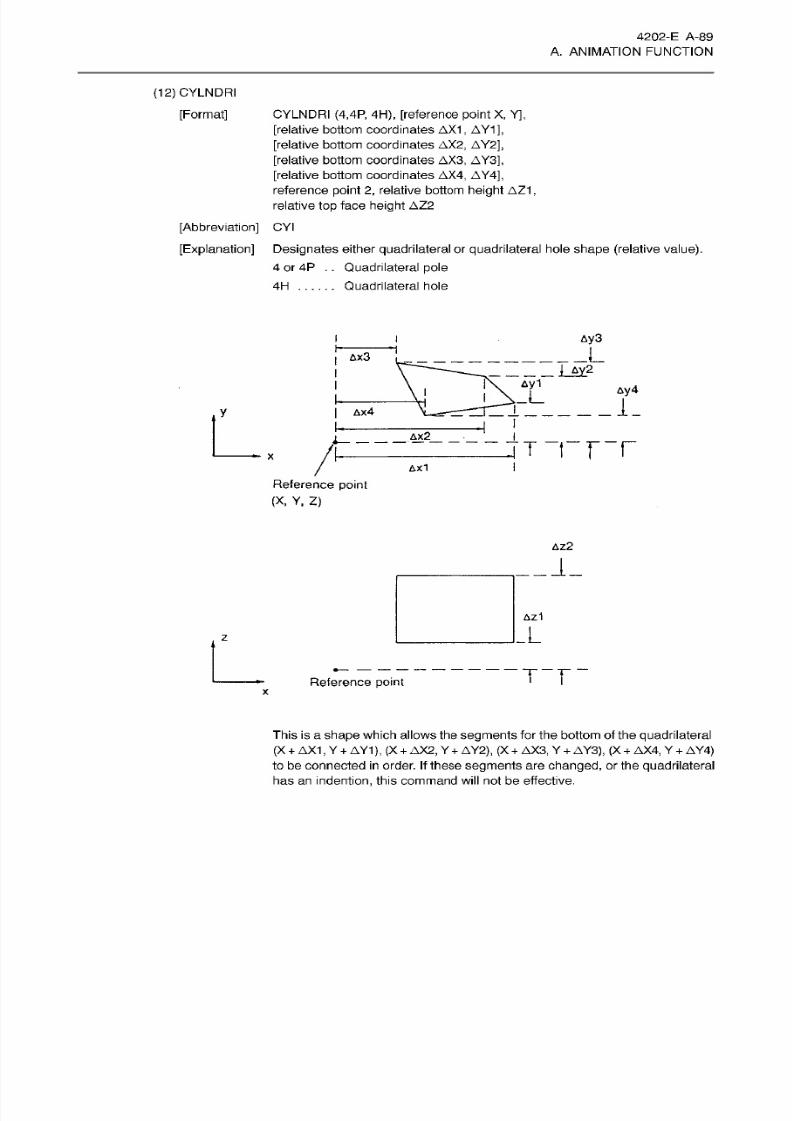
8/15/2019 Okuma Manuals 391
http://slidepdf.com/reader/full/okuma-manuals-391 116/397
4202-E
A-89
A. ANIMATION FUNCTION
(12)
CYLNDRI
[Format] CYLNDRI (4,4P, 4H), [reference
point X,
Y],
[relative bottom coordinates
AX1
, AY1],
[relative
bottom coordinates
AX2,
AY2],
[relative
bottom
coordinates
AX3,
AY3],
[relative
bottom
coordinates
AX4,
AY4],
reference
point
2, relative bottom
height
AZ1,
relative
top
face
height AZ2
[Abbreviation]
CYI
[Explanation]
Designates
either
quadrilateral
or quadrilateral
hole
shape (relative value).
4
or
4P . .
Quadrilateral
pole
Quadrilateral
hole
H
Ay3
L
x3
__
I
&y2
Ay1
Ay4
_L
1
_
x4
AX2_
T T T T
AX l
Reference
point
(X ,
Y,
Z)
AZ2
Az1
z
T“T
eference
point
x
This
is a shape
which allows
the
segments
fo r
the bottom
of the quadrilateral
(X
+
AX 1,
Y
+
AY1
),
(X
+
AX2,
Y
+
AY2),
(X
+
AX3,
Y
+
AY3),
(X
+
AX4, Y
+
AY4)
to
be connected
in
order.
If
these
segments
are changed,
or
the
quadrilateral
has
an
indention,
this command
will
not be
effective.
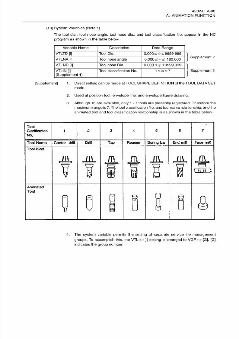
8/15/2019 Okuma Manuals 391
http://slidepdf.com/reader/full/okuma-manuals-391 117/397
4202-E A-90
A. ANIMATION FUNCTION
(13)
System Variables
(Note 1)
The tool
dia.,
tool nose
angle,
tool
nose dia.,
and tool classification
No.
appear
in
the NO
program
as shown
in
the table
below.
Variable Name
Description
Data
Range
VTLTD
[I]
Tool
Dia.
0.000<
+
<
9999.999
Supplement
2
VTLNA
[I]
Tool
nose angle 0.000<
+
<
180.000
VTLND
[I] Tool
nose
Dia.
0.000
<
+
<9999.999
Supplement
3
TLIN
[I]
(Supplement
4)
Tool
classification No.
1
<
+
<
7
[Supplement]
1.
Direct
setting
can
be made at TOOL SHAPE
DEFINITION
of the TOOL DATA
SET
mode.
2.
Used at
position
tool,
envelope line,
an d
envelope figure drawing.
3.
Although
16
are available,
only
1
-
7
tools are presently registered.
Therefore
the
maximum range is
7.
The
tool classification No. and tool name
relationship,
and the
animated
tool and
tool
classification
relationship
is
as
shown
in
the
table
below.
Tool
Clarification
6
7
3
4 5
No,
Boring
bar End
mill
Face
mill
ap
Reamer
ool
Name
Center
drill
Drill
Tool
Kind
M
JL
casÿ
Animated
Tool
§
17
4.
The system
variable
permits
the
setting
of
separate
service li fe
management
groups. To
accomplish
this,
the
VTL++[I]
setting
is
changed
to VGR++[G].
[G]
indicates the group number.
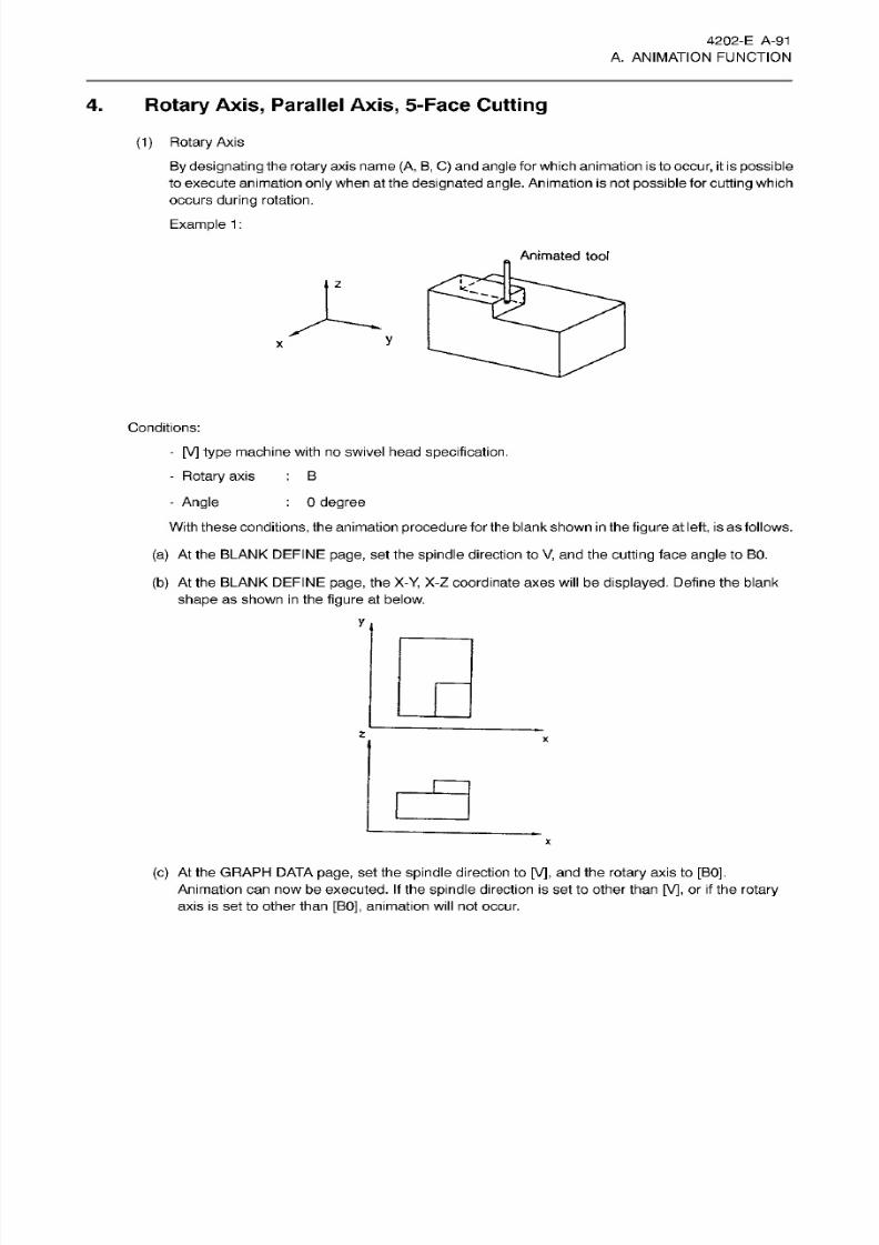
8/15/2019 Okuma Manuals 391
http://slidepdf.com/reader/full/okuma-manuals-391 118/397
4202-E A-91
A. ANIMATION FUNCTION
4. Rotary
Axis,
Parallel Axis, 5-Face
Cutting
(1)
Rotary
Axis
By designating
the rotary
axis
name (A, B, C) and
angle
for
which animation is to
occur,
it
is
possible
to execute
animation
only
when at the
designated angle.
Animation is not
possible
for
cutting
which
occurs
during
rotation.
Example
1
:
Animated
tool
z
y
X
Conditions:
-
[V]
type
machine
with
no swivel head
specification.
-
Rotary axis
B
-
Angle
With
these
conditions,
the animation
procedure
fo r the blank
shown in
the
figure
at
left,
is as follows.
(a)
At
the
BLANK
DEFINE page,
set the
spindle
direction to
V,
and the
cutting
face
angle
to BO.
(b)
At
the
BLANK
DEFINE page,
the
X-Y,
X-Z
coordinate
axes
will
be
displayed.
Define
the blank
shape
as shown in the figure
at
below.
0
degree
z
X
(c)
At
the
GRAPH
DATA page,
set
the
spindle
direction
to [V],
and the
rotary
axis
to
[BO].
Animation
can now
be executed.
If
the
spindle
direction is set to
other than
[V],
or
if
the
rotary
axis is
set to other
than
[BO],
animation
will
not
occur.
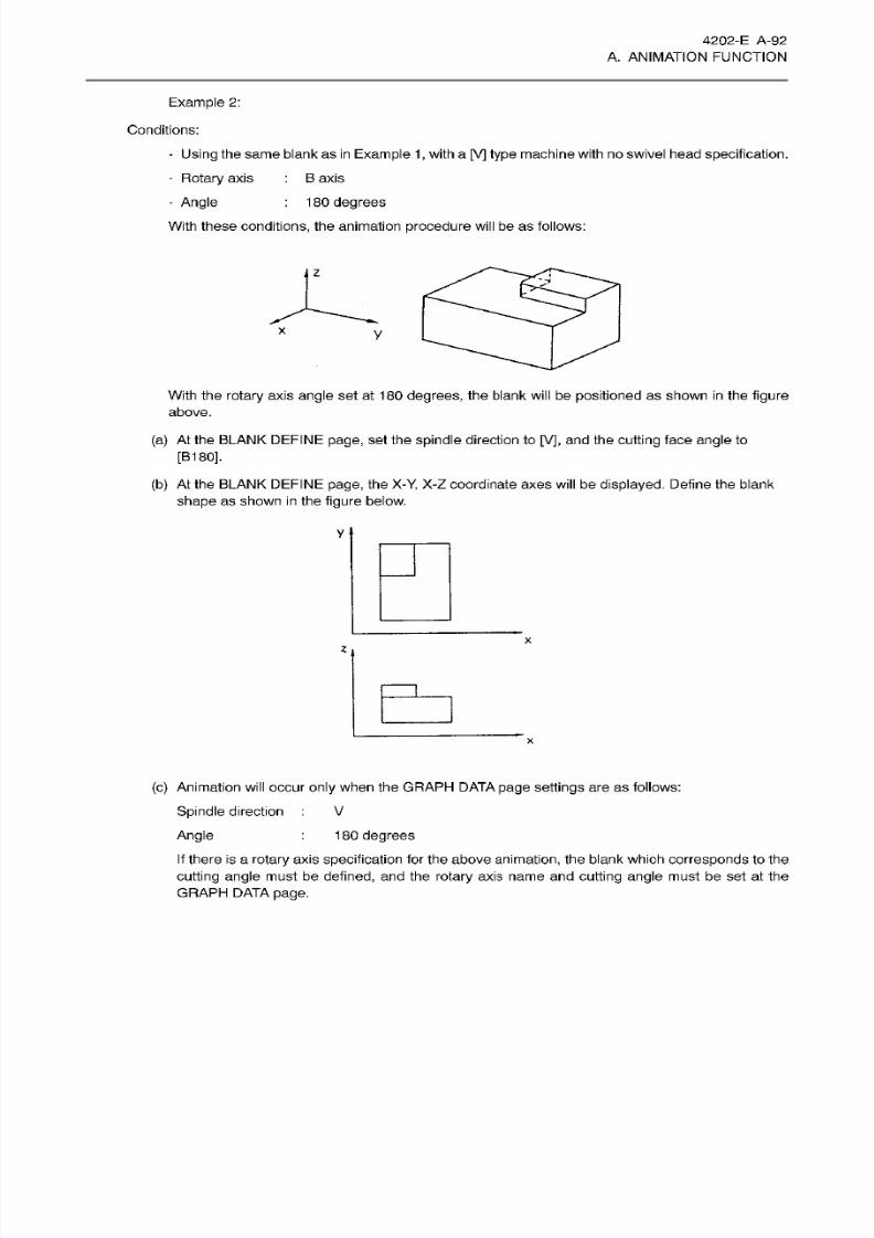
8/15/2019 Okuma Manuals 391
http://slidepdf.com/reader/full/okuma-manuals-391 119/397
4202-E A-92
A. ANIMATION FUNCTION
Example
2:
Conditions:
- Using
the
same
blank as
in Example
1, with a [V]
type
machine with no swivel head specification.
- Rotary
axis
B
axis
- Angle
180
degrees
With these
conditions,
the
animation procedure
will
be
as follows:
z
2
X
y
With
the
rotary
axis angle set at
180
degrees,
the
blank will
be
positioned
as
shown in
the
figure
above.
(a)
At
the
BLANK
DEFINE page,
set
the
spindle direction
to
[V],
and
the
cutting face angle
to
[B180].
(b)
At
the
BLANK
DEFINE page,
the X-Y,
X-Z coordinate
axes
will
be
displayed. Define
the
blank
shape
as
shown
in
the
figure
below.
V
x
z
(c)
Animation will occur
only
when the
GRAPFI
DATA
page settings
are as fol lows:
Spindle
direction
V
Angle
1
80
degrees
If there
is a rotary
axis
specification for the above animation,
the
blank which
corresponds
to the
cutting
angle
must be defined, and the
rotary
axis name and cutting
angle
must
be
set
at the
GRAPH
DATA page.

8/15/2019 Okuma Manuals 391
http://slidepdf.com/reader/full/okuma-manuals-391 120/397
4202-E A-93
A. ANIMATION FUNCTION
(2 )
5-face Cutting
With swivelhead specification, the spindle direction
setting
where animation is desired
in
the
same
manner
as
the
rotary
axis, must be
set
when defining the blank.
For animation to
occur,
the
spindle direction, rotary
axis
name,
and
cutting angle settings
which are
made
at
the
BLANK
DEFINE
page
must
match
the
spindle
position
and
rotary
axis
designations
made
at the GRAPFI DATA
page.
If
animation is to occur
from various
angles
depending
on
the
spindle
direction
and
cutting angle,
each
spindle direction
and
cutting angle setting
which determines the blank
shape
must be defined.
Furthermore,
the
GRAPH
DATA
designations
must match these
settings
for animation to
occur.
(3)
Parallel Axis
The
parallel
axis
(U ,
V, W)
applies
only
to
the
NO
axis. The
following
3
master/slave
axis selections
are
possible
at the GRAPH DATA page:
-
Master axis
only
-
Slave axis
only
-
Master
axis
+
slave axis
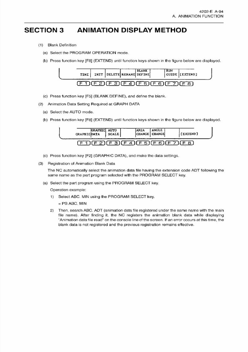
8/15/2019 Okuma Manuals 391
http://slidepdf.com/reader/full/okuma-manuals-391 121/397
4202-E A-94
A. ANIMATION FUNCTION
SECTION 3 ANIMATION DISPLAY METHOD
(1)
Blank
Definition
(a)
Select the PROGRAM OPERATION mode.
(b)
Press
function
key
[F8]
(EXTEND)
until function
keys
shown
in
the figure below
are
displayed.
I
J
LANK
INIT
DELETE
RENAME
DEFINE
RUN
GUIDE
[EXTEND]
IKE
fTÿirÿrFÿrFÿ~irF~5l(~F~6lfT~7irF~8l
(c)
Press
function
key
[F5]
(BLANK
DEFINE),
and
define
the
blank.
(2)
Animation Data Setting Required
at
GRAPH
DATA
(a)
Select the
AUTO
mode.
(b)
Press
function
key
[F8]
(EXTEND)
until
function keys
shown
in
the figure
below
are
displayed.
AREA
ANCLE
CHANGE CHANGE
GRAPHIC
AUTO
GRAPHIC
DATA
SCALE
[EXTEND]
ITT1(TinfT3l(Tÿ(TTnfT~6 l(TTirFiri
(c) Press function
ke y
[F2]
(GRAPHIC
DATA), and make the data
settings.
(3)
Registration
of
Animation
Blank Data
The NO
automatically
select the animation data
file having
the extension
code AD T
following the
same name as
the part program
selected with the PROGRAM
SELECT key.
(a) Select the part
program
using
the PROGRAM SELECT
key.
Operation example:
1
) Select
ABC. MIN
using
the
PROGRAM SELECT
key.
=
PS
ABC. MIN
2)
Then,
search
ABC. ADT
(animation data
file registered
under
the same
name
with the main
file
name).
After
finding
it,
the
NO
registers
the
animation
blank data
while
displaying
“Animation datafile read”
on the console line of
the
screen.
If
an error
occurs
at this
time,
the
blank
data
is
not
registered
and
the previous
registration
remains effective.
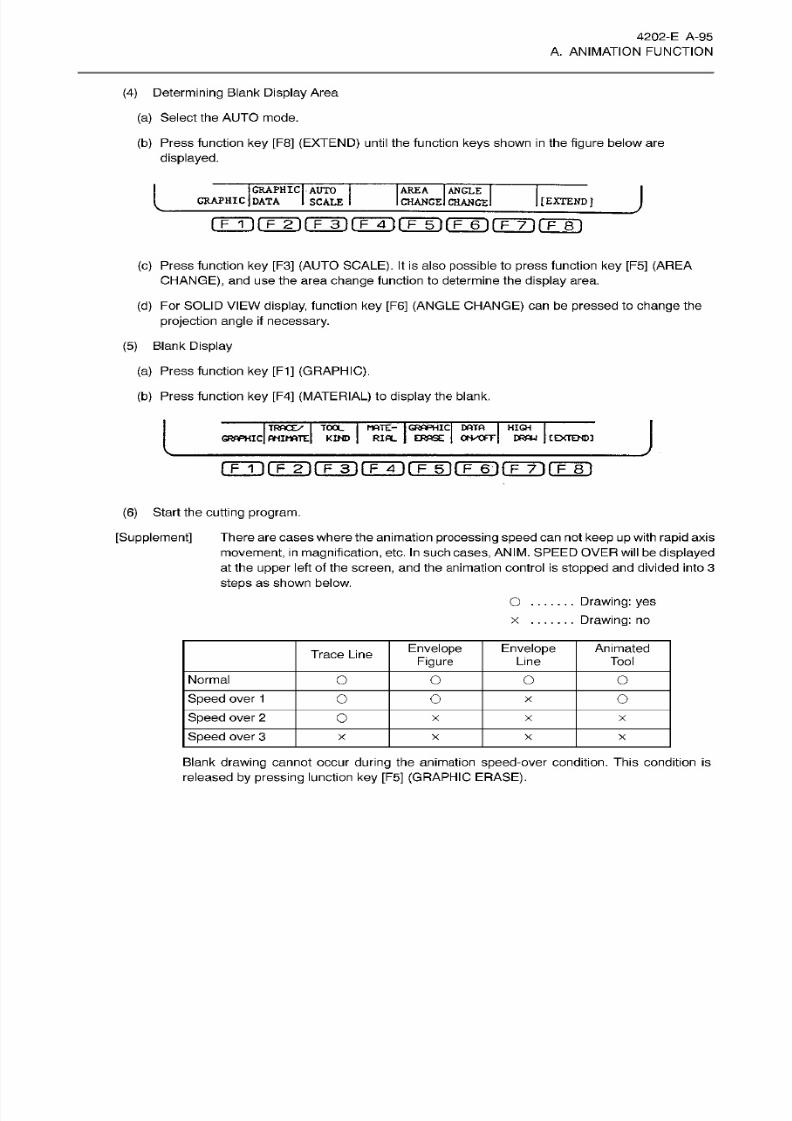
8/15/2019 Okuma Manuals 391
http://slidepdf.com/reader/full/okuma-manuals-391 122/397
4202-E A-95
A. ANIMATION FUNCTION
(4) Determining
Blank
Display
Area
(a) Select the AUTO mode.
(b) Press function
ke y
[F8]
(EXTEND)
until
the
function
keys
shown
in
the
figure
below are
displayed.
I
J
RAPHIC
AUTO
GRAPHIC
DATA
SCALE
AREA
ANGLE
CHANGE
CHANGE
[EXTEND]
(c)
Press
function
key [F3]
(AUTO
SCALE).
It is
also possible
to
press function key [F5]
(AREA
CHANGE),
and use the area
change
function to
determine the
display
area.
(d)
For SOLID
VIEW display,
function
ke y
[F6]
(ANGLE CHANGE)
can be pressed
to
change
the
projection angle
if
necessary.
(5)
Blank
Display
(a) Press function
ke y
[F1]
(GRAPHIC).
(b)
Press function
ke y
[F4] (MATERIAL) to
display
the blank.
I
J
OOL
j
MATE:-
|
GRAPHIC
DATA I HIGH I
KIND
RIAL
ERASE
OrVCFTj
DRAW
I
C
EXTEND]
I TRACE/
I
GRAPHIC
ANIMATE
f~Fin
jT~4l (~F~5l fF~6~)
f~F~8~l
(6)
Start
the
cutting
program.
[Supplement]
There are
cases where
the animation
processing speed can
not
keep
up
with
rapid
axis
movement, in magnification,
etc.
In
such cases, ANIM.
SPEED OVER
will be
displayed
at the upper lef t
of the
screen, and
the
animation control
is
stopped and divided
into
3
steps
as shown
below.
Drawing:
ye s
Drawing:
no
O
x
Envelope
Figure
Envelope
Line
Animated
Tool
race Line
Normal
O o o o
Speed
over
1
O O
o
Speed
over
2
O
x x
X
Speed
over
3
x
x x
X
Blank
drawing
cannot occur
during
the animation speed-over condition. This condit ion
is
released
by
pressing lunction
key [F5]
(GRAPHIC
ERASE).

8/15/2019 Okuma Manuals 391
http://slidepdf.com/reader/full/okuma-manuals-391 123/397
B.
TOOL
PATH DISPLAY
FUNCTION
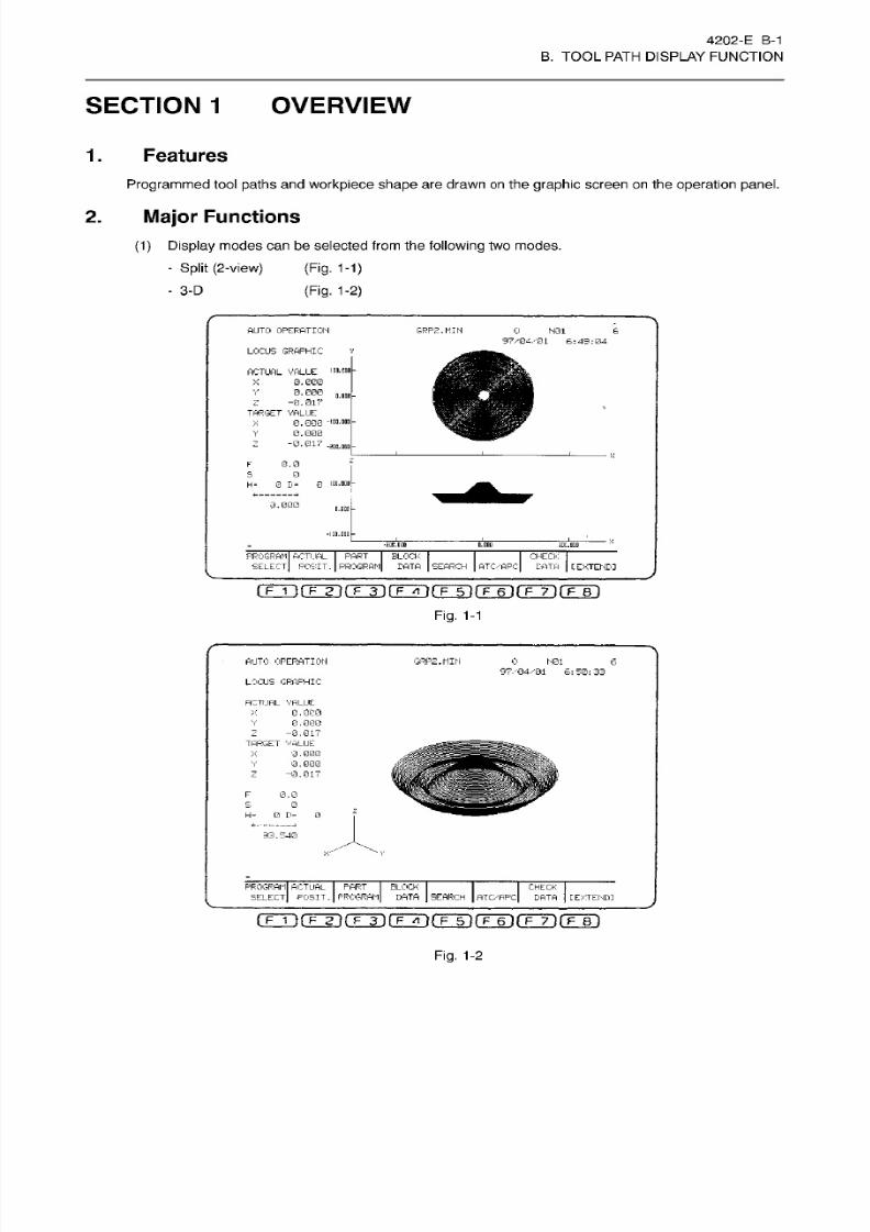
8/15/2019 Okuma Manuals 391
http://slidepdf.com/reader/full/okuma-manuals-391 124/397
4202-E
B-1
B.
TOOL
PATH DISPLAY FUNCTION
SECTION
1 OVERVIEW
Features
.
Programmed
tool paths an d workpiece shape
are
drawn
on
the
graphic screen on
the
operation
panel.
Major Functions
.
0)
Display
modes can be
selected
from
the following two modes.
- Split
(2-view)
-
3-D
(Fig.
1-1)
(Fig.
1-2)
AUTO OPERATION GRP2.MIN
0
N01
6
97/04/01
6:49:04
LOCUS GRAPHIC
i
on .
coo
ACTUAL
VALUE
0.000
0
.
000
-0.01?
TARGET
VALUE
X
K/
O.flDO
0.000
-100.000
0.000
“0.017
X
Y
Z
-SOB-
QUO
X
0.0
s
0
0
IDO-ODD
-
H- 0 D=
0.000
0.000
-100.000
X
i00.000
n.ooo
iDC.QDD
PROGRAM
ACTUAL PART
SELECT
POSIT.
PROGRAM
BLOCK
BATA
SEARCH
CHECK
E'ATA
TC/APC
[EXTEND]
(
F
1
)(F
2
|(
F
3)[ FT»'
It
F
5)(T~6T(
F
7)fTB)
Fig.
1-1
AUTO
OPERATION GRP2.MIN
O
N01
6
97/04/01
6:50:33
LOCUS
GRAPHIC
ACTUAL
VALUE
0.000
0
.00O
-0.017
TARGET
VALUE
0
.
000
0.000
-0.017
X
V
z
X
Y
mm
Z
wBrn
0.0
/C
s
0
z
H= 0
P=
0
«
9
93.54G
...ÿ*ÿ
Y
PROGRAM
ACTUAL
PART
BLOCK
SELECT POSIT. PROGRAM DATA SEARCH
ATC/APC
CHECK
DATA
[EXTEND:
I
F
1
)fF~~2T(
f
3)f FT»')fF~5l(T~6:rF~7:rFTl
Fig. 1-2

8/15/2019 Okuma Manuals 391
http://slidepdf.com/reader/full/okuma-manuals-391 125/397
4202-E
B-2
B. TOOL PATH DISPLAY FUNCTION
(2 )
Drawing
speed
can
be selected from the
following
two modes.
- Programmed
feedrate
-
High drawing
speed
(3)
Display
position and scale can be
changed
while
looking
at tlte tool paths
being
drawn.
(4)
Programmed
shape
display
without actual axis
movements
is possible.
(5)
With 3-D
display mode,
view
angle (elevation
and rotation angles)
can
be
changed
as
required
so that
the
operator
can
check the
programmed
shape
in any angle from any height
level.
(Fig.
1-3)
I
AUTO
OPERATION GRP3.UIN
_0
JL
6_
|
97/07/15
UTTOTOO'
PLANE CHANGE
HEIGHT
25
OIREC.
45
CENTER
X
0.
000
Y
0.
000
Z 200.000
+X
-X
+Y
-Y
+Z
-Z
96.999
>Q
=G A
>GV
>
ANGLE
CHANGE
AREA
PLANE
C
CHANGE
QUIT
rÿT)rTTi (TÿrFÿ(TT)(TÿrF~T)rF~ei
Fig.
1-3
(6)
Restart and
sequence
restart
operations
are both
possible.
(7)
Zero
offset,
cutter
radius offset and
3-D
offset data
are al l added
to draw
the
programmed
tool
paths.

8/15/2019 Okuma Manuals 391
http://slidepdf.com/reader/full/okuma-manuals-391 126/397
4202-E B-3
B. TOOL PATH DISPLAY FUNCTION
SECTION 2 SETTING
OF
DISPLAY
DATA
Set
the data
necessary
for drawing the programmed
tool
paths,
as
required.
Data
Setting
in
the
Graphic
Data
Mode
.
Operation
procedure:
(1)
Select
any
of
the following
operation
modes:
-
AUTO
- MDI
-
MANUAL
(2) Press function
key [F8] (EXTEND)
until the
screen displays
the function
key names
indicated
below.
• EX
-EX
CAflPHIC
ERASE
GRAPHIC PLANE
GRAPHIC]
DATA
OPNGE
t
EXTENDI
rFTl
fF~5l
fF~6n
fF~7l
r~F~8~l
(3)
Press
function
ke y
[F1]
(GRAPHIC).
(4)
Press function
ke y [F2] (GRAPHIC DATA).
AUTO
OPERATION
GRP3.I1IN
0
6
97/04/01
2; 52 ;
09
GRAPH DATA lrnm
PLANE
SELECT
Q
C0:Not draw
1:XY
2:
YZ
3:XZ
4
;
XY-XZ
5:ZY“XY
6:XYZ
7;ZXY)
(0:Do
not-
l:Do)
APID P. DRAW
1
GRAPHIC ZERO
X
0.000
0.000
0.000
I
'GRAPH.
COOR
.
0
;
IHVAL
.
/I
:
VAL .
0
Y
Z
|
GRAPH. COOR.
NUMBER
1
GRAPHIC
AREA
X
350.000
Y
350.000
Z 353.000
V ANGLE DIREC 45
HIGH 25
>;
Angle -from axis
X)
(Angle
from
horizontal
leL'el)
=GD
>
GR.
SET
QUIT
ET
COD
CODCOD
COD
CODCODCOD
CfJL)
(5)
Press the cursor keys (ff)
,
(ZP)
to locate
the cursor
on the desired data
position.
For the data displayed
on
the screen,
refer
to 2, “Graphic data Display Parameters”.
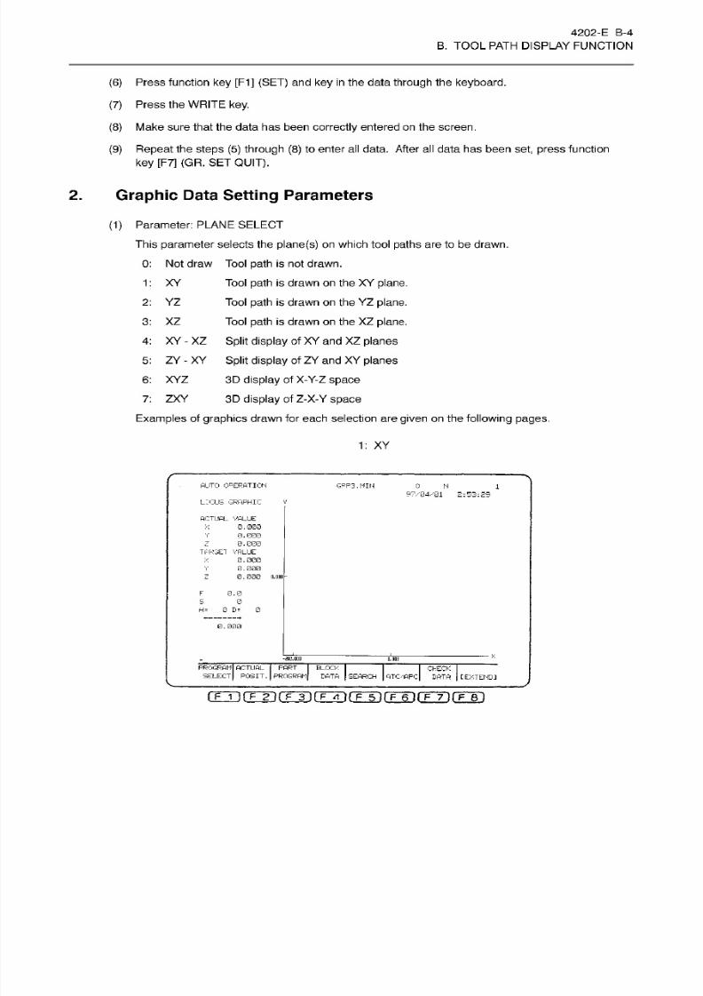
8/15/2019 Okuma Manuals 391
http://slidepdf.com/reader/full/okuma-manuals-391 127/397
4202-E
B-4
B. TOOL PATH DISPLAY FUNCTION
(6) Press function
key [F1]
(SET)
and
key in the data through
the
keyboard.
(7)
Press the
WRITE key.
(8)
Make
sure that
the
data has been
correctly
entered on
the
screen.
(9)
Repeat the
steps
(5)
through
(8)
to
enter
all data.
After
all data has been
set,
press
function
ke y
[F7]
(GR.
SET
QUIT).
2.
Graphic
Data
Setting
Parameters
(1)
Parameter:
PLANE
SELECT
This
parameter selects the
plane(s)
on
which
tool
paths
are to be
drawn.
0:
Not draw
Tool
path
is
not drawn.
Tool
path
is drawn on the
XY
plane.
Tool
path
is
drawn
on
the
YZ
plane.
Tool
path
is drawn on the
XZ
plane.
4: XY
-
XZ
Split
display
of
XY
and
XZ
planes
5: ZY
-
XY
Split
display
of
ZY
an d
XY
planes
3D
display
of
X-Y-Z
space
3D
display
of
Z-X-Y
space
Examples
of
graphics
drawn
for each selection are
given
on
the
following pages.
1: XY
2:
YZ
3:
XZ
6: XYZ
7: ZX Y
1: XY
AUTO
OPERATION
GRP3.MIH
0
N
1
97/04/01
2:53:29
LOCUS
GRAPHIC
ACTUAL
VALUE
0.0SO
0.000
0.000
TARGET
VALUE
0.000
0.000
0.000
on
X
V
z
X
V
z
F
0.0
5
• J
H=
0
D»
0
0.000
/
B.ND
PROGRAMI ACTUAL
PART
BLOCK
SELECT)
POSIT.
PROGRAM
DATA
SEARCH
ATC/APC
CHECK
DATA
C
EXTEND]
rrTifrÿrrrinÿnHrinHnfTÿiTT')

8/15/2019 Okuma Manuals 391
http://slidepdf.com/reader/full/okuma-manuals-391 128/397
4202-E B-5
B.
TOOL
PATH
DISPLAY FUNCTION
2: YZ
AUTO OPERATION
GRP3.MIN
0
N 1
97/04/01
2:54:24
LOCUS
GRAPHIC
z
ACTUAL
VAJJE
0.000
0,000
0
.000
TARGET
VALUE
0.000
0.000
0.000
X
Y
—y
X
Y
Z
O.CDO-
F
0.0
0
0 D-
0
=
0,000
V
-SOD.
00Q
.COD
—
PROGRAM ACTUAL
PART
SELECT
PC S
IT . PROGRAM
BLOCK
DATA
CHECK
DATA
EARCH
ATC/APC
[EXTENDI
i
F
1
)fm(
E
3)rÿTnr5ifT~6irF~7irFTi
3:
XZ
AUTO
OPERATION
GRP3.MIN 0 N
1
97/04/01 2:
97 ;
53
LOCUS
GRAPHIC
ACTUAL
VALUE
0.G00
0
.
000
0.
000
TARGET
VALUE
0.000
0.000
0.000
X
V
z
X
V
z
0.0
DC
0.0
e
H«
0
D=
0
-i
0.000
X
-EDS. ODD
o.oas
PROGRAM
ACTUAL
PART
SELECT
POSIT. PROGRAM,
BLOCK
DATA SEARCH
ATC/APC
CHECK
DATA
[EXTEND]
(TT]rF2]rF3)(FÿrFTurFT]rF~7irF~Bi
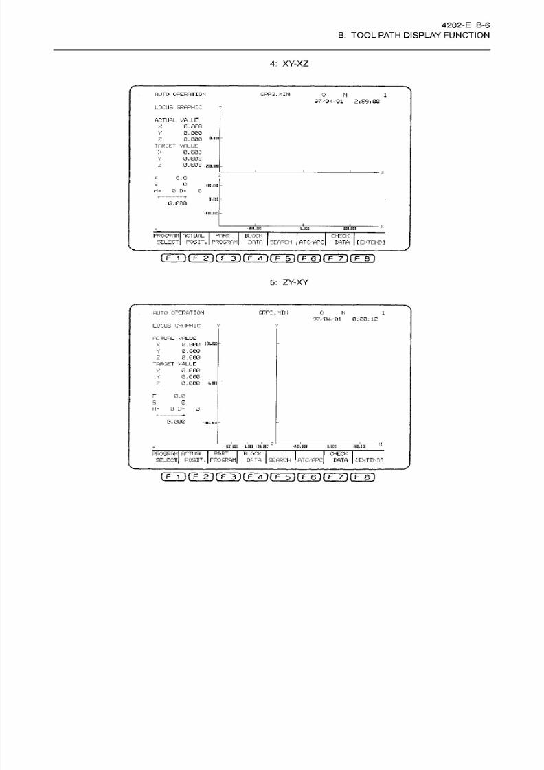
8/15/2019 Okuma Manuals 391
http://slidepdf.com/reader/full/okuma-manuals-391 129/397
4202-E
B-6
B.
TOOL
PATH
DISPLAY FUNCTION
4:
XY-XZ
AUTO OPERATION GRP3.MIN
0
N
1
97/04/01
2:59:08
LOCUS GRAPHIC
Y
ACTUAL
VALLE
0.000
0. 000
0.000
TARGET
VALUE
0.000
0
.
000
0
.
000
X
Y
D.dDO
X
Y
Z
-2D
D.DDO
0.0
S
0
IOD.DDD
H=
0
D
=
0
*-
D.DOD
0.000
• I DE .ODD
X
-3ED. DUD
D.DDD
300.
ODD
PROGRAM
I
ACTUAL
SELECT
PART
POSIT.
I
PROGRAM
BLOCK
BATA
CHECK
I
DATA
I
CEXTENDI
EARCH
ATC/'APC
I
F
1
IfTTll
F
3
}rF~5~irP60rÿ70(TBl
5:
ZY-XY
AUTO
OPERATION
GRP3.NIH
0
H
1
97/04/01
0:00:12
LOCUS GRAPHIC
v
ACTUAL
VALUE
0 . 000
0
.
000
0
.
000
TARGET VALUE
3.000
0.000
0.000
300.DEC
V
z
Y
—
a. BAD
F
0.0
0
0
=
0
D=
0. 000
-3DD.ID0
£
X
-IDD.DDD
D.DDD
IDO.
DEC
-2DD.DDD D.DCD EDD.DDD
PROGRAM ACTUAL
PART
SELECT
POSIT,
PROGRAM,
BLOCK
DATA
SEARCH
ATC/APC,
CHECK
DATA
[EXTEND]
(FTirrÿrÿ(Fÿ(Fÿrÿrr7irF~Bi
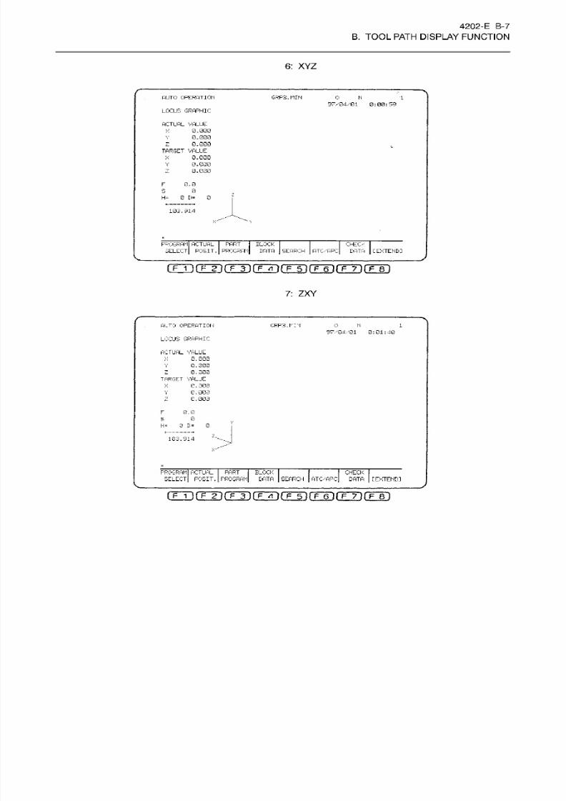
8/15/2019 Okuma Manuals 391
http://slidepdf.com/reader/full/okuma-manuals-391 130/397
4202-E
B-7
B.
TOOL
PATH
DISPLAY FUNCTION
6:
XY Z
AUTO
OPERATION
GRP3.MIN
0 N
1
97/04/01
0:00:59
LOCUS
GRAPHIC
ACTUAL
VALLE
0 .
000
0.
000
0.000
TARGET
VALUE
0
.
000
0.000
0.000
X
V
X
Y
z
0.0
s
0
H= 0 D= 0
103.914
<;
PROGRAM
ACTUAL PART
SELECT
POSIT
.
PROGRAM
BLOCK
DATA
CHECK
DATA
EARCH PTC/
ARC
[EXTEND:
I
F
1
imnt
F
3
1
f~p~4
}rF~5~irÿ6Trÿ7T(TeT
7:
ZX Y
ALTO
OPERATION
GRP3.rr'i 0
N
1
37/04/01
0:01:40
LOCUS GRAPHIC
ACT UAL VAL UE
Q
,
0G 0
0/000
0.
000
TARGET VALUE
0.
300
0,000
0
.
000
X
Y
Z
X
Y
2
F 0.0
0
3
B= 0
=
z...
GJ.S14
>
PROGRAM ACTUAL
PART
SELECT POSIT. PROGRAM
BLOCK
I
DATA
SEARCH
I
ATC/APC
CHECK
DATA
[EXTENDI
(TTirF2irF3)(FFrirFÿrFT:rF~TÿrF~Bi
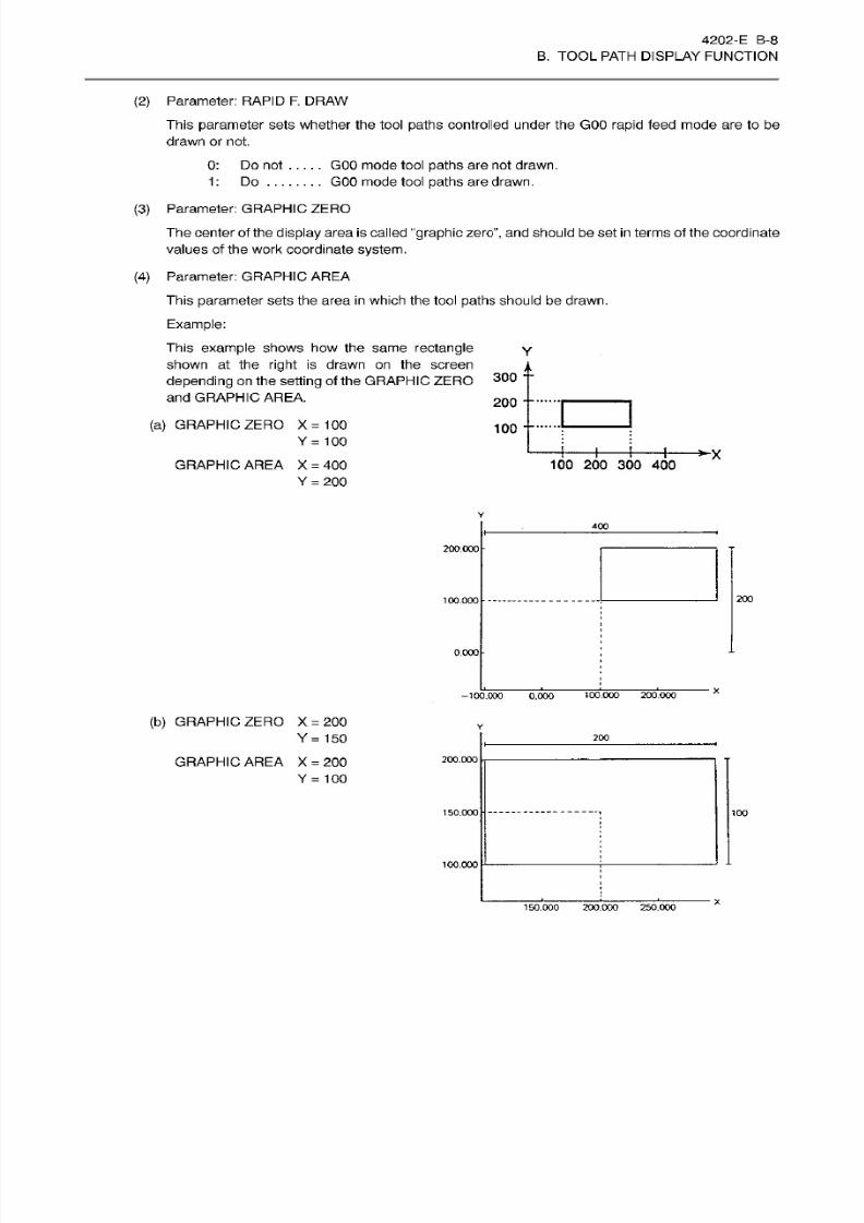
8/15/2019 Okuma Manuals 391
http://slidepdf.com/reader/full/okuma-manuals-391 131/397
4 20 2-E B -8
B.
TOOL
PATH DISPLAY FUNCTION
(2) Parameter:
RAPID F. DRAW
This
parameter
sets
whether
the tool
paths
controlled
under
the GOO rapid feed mode
are
to be
drawn or not.
0:
Do not
1
:
Do
. . .
GOO
mode tool
paths
are
not drawn.
GOO
mode tool
paths
are
drawn.
(3)
Parameter: GRAPHIC ZERO
The center
of
the
display
area is called
graphic
zero”,
an d should be set
in
terms of the coordinate
values of the
work
coordinate
system.
(4)
Parameter: GRAPHIC
AREA
This parameter sets
the area
in
which the tool
paths
should be
drawn.
Example:
This
example
show s h ow the
same
rectangle
shown at the
right
is
drawn on the screen
depending
on
the
setting
of
the
GRAPHIC
ZERO
and GRAPHIC
AREA.
300
--
200
--
(a)
GRAPHIC ZERO
X=100
Y=
100
10 0
--
I
100 200
300
40 0
RAPHIC
AREA X
=
40 0
Y
=
200
400
200.000
200
00.000
0.000
X
100.000
200.000
100.000
0.000
(b) GRAPHIC ZERO X
=
200
Y
=
150
20 0
200.000
GRAPHIC
AREA X
=
200
Y
=
100
150.000
100
100.000
150.000 200.000 250.000
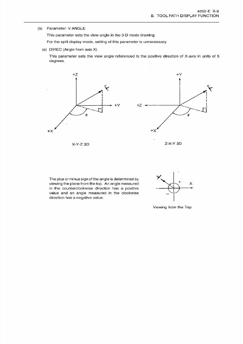
8/15/2019 Okuma Manuals 391
http://slidepdf.com/reader/full/okuma-manuals-391 132/397
4202-E
B-9
B. TOOL PATH DISPLAY FUNCTION
(5) Parameter:
V
ANGLE
This
parameter
sets the view
angle in
the 3-D mode
drawing.
For the split
display mode, sett ing
of this
parameter
is
unnecessary.
(a) DIREC
(Angle
from
axis X)
This
parameter sets
the
view
angle
referenced to the positive direction
of
X-axis in units
of
5
degrees.
+Y
Z
%
Y
+Y
8 8
+X
X
Z-X-Y
3D
-Y-Z
3D
The
plus
or
minus sign
of
the angle
is
determined by
viewing
the
plane
from the
top.
An angle measured
in the counterclockwise direction
has
a
positive
value and an
angle
measured
in
the clockwise
direction has a
negative
value.
+
X
Viewing
from
the Top
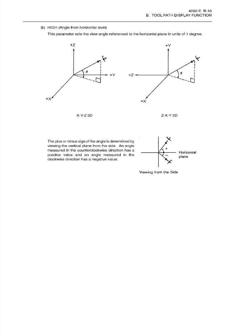
8/15/2019 Okuma Manuals 391
http://slidepdf.com/reader/full/okuma-manuals-391 133/397
4202-E B-10
B. TOOL PATH DISPLAY FUNCTION
(b) HIGH
(Angle
from horizontal level)
This
parameter
sets the view
angle
referenced to
the
horizontal plane
in units
of
1
degree.
+Z
+Y
V
Y
e
6
+Y
-d
+X'
+x
X-Y-Z
3D
Z-X-Y
3D
The
plus
or minus
sign
of the
angle is
determined
by
viewing
the vertical plane from
the
side.
An
angle
measured
in
the counterclockwise direction has
a
positive
value and an
angle
measured
in
the
clockwise
direction
has
a
negative
value.
+
Horizontal
plane
X
Viewing
from
the
Side
8/15/2019 Okuma Manuals 391
http://slidepdf.com/reader/full/okuma-manuals-391 134/397
4202-E
B-11
B. TOOL PATH DISPLAY FUNCTION
(6) Parameter:
GRAPH.
COOR.
The work coordinate
system
solely used
for
drawing can
be
registered as
the
graphic
coordinate
system. This
coordinate
system
is very
convenient for
drawing
the
programmed tool
paths
and
cutting
processes
on the screen
screen, using
a
single
coordinate
system independent
of the work
coordinate
systems
used in
a
part
program.
This
parameter
sets whether the
graphic
coordinate
system
is
made
effective
or
ineffective.
0: To make the
graphic
coordinate
system
ineffective.
Drawing
is conducted sothat
the
origin
of
the
work coordinate
system
in
a
part
program
is set
at
the center of
the
graphic display
((X, Y, Z)
=
(0,
0,
0)).
1: To
make
the
graphic
coordinate
system
effective.
Drawing
is conducted so that
the origin
of
the graphic coordinate
system
is
set
at the
center of
the
graphic display
((X, Y,
Z)
=
(0.
0, 0)).
Note: Whether the
graphic
coordinate
system
is
made
effective or
not
when
power supply
to the
control
is
turned
on or
when
it
is
reset,
can be
determined
by
the
setting
ofNC optional
parameter
(bit)
No .
33
bit 0.
(7)
Parameter: GRAPH. COOR.
NUMBER
Th e
number
for
the work coordinate
system solely
used
fo r graphic drawing can
be set
as
the
graphic
coordinate
system
number.
Setting
range: 0-100
Machine coordinate
system
Work
coordinate
system
number
Note
1:
Once
set,
the
graphic
coordinate
system
number is not cleared when the controlis reset
or
power
supply
to
the
control
is
turned
off.
0
1-100
Note
2:
Setting range
is
0
-
100 as stated
above.
If
a
value
greater
than the
maximum
number
of
work coordinate
system
sets is
set, drawing
is made on
the machine coordinate
system
depending
on
the
specification.
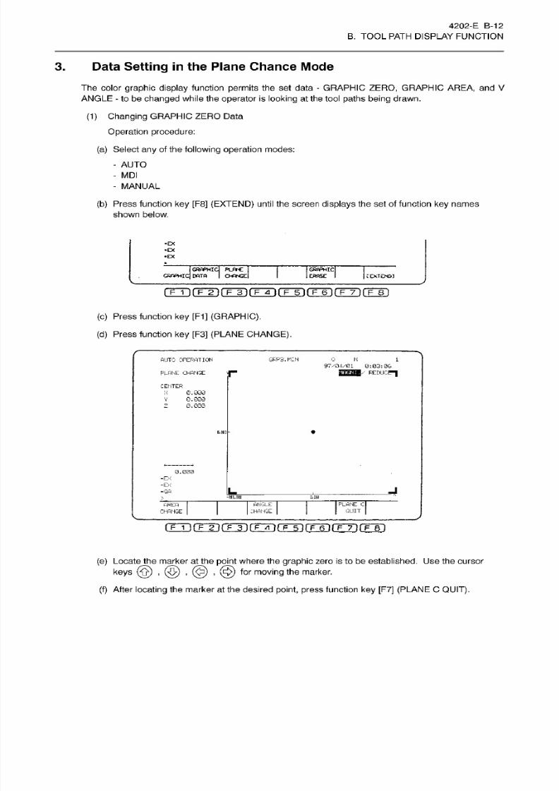
8/15/2019 Okuma Manuals 391
http://slidepdf.com/reader/full/okuma-manuals-391 135/397
4202-E
B-12
B. TOOL PATH DISPLAY FUNCTION
3. Data Setting in the Plane Chance Mode
The color
graphic display
function
permits
the
set data
-
GRAPHIC
ZERO,
GRAPHIC
AREA, and V
ANGLE
-
to be
changed
while the operator is
looking
at
the tool
paths
being
drawn.
(1)
Changing
GRAPHIC
ZERO
Data
Operation procedure:
(a)
Select
any
of
the
following
operation
modes:
AUTO
-
MDI
-
MANUAL
(b)
Press function
key
[F8] (EXTEND) until the
screen displays
the set of function
key
names
shown below.
• EX
• EX
1
RAPHI
OWPHZq
DATA
PLATE
|
OANGEl
GRAPHIC
ERASE I L
EXTENDS
fTÿfTTi(TÿiTÿrpÿrF~6irrTirF~8i
(c)
Press function
key
[F1]
(GRAPHIC).
(d)
Press
function
key
[F3]
(PLANE CHANGE).
AUTO OPERATION
GRP3.MIN
0
N
1
97/04/01 0:03:06
REDUCER
LANE
CHANGE
CENTER
X
0.000
0.000
0.000
V
z
*
.DH0
0.000
=EX
-ÿ4
GA
-290.0110
0.010
ANGLE
CHANGE
PLANE C
QUIT
AREA
CHANGE
nmrrÿrÿrFGÿrr5)rÿ6irr7irF~ri
(e)
Locate the marker
at
the
point
where the
graphic
zero is to
be
established.
Use
the cursor
keys
(0)
,
(5)
,
@ )
,
@
for
moving
the
marker.
(f)
After
locating
the
marker at
the desired
point,
press
function
key [F7]
(PLANE
C
QUIT).
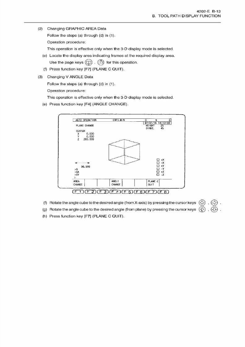
8/15/2019 Okuma Manuals 391
http://slidepdf.com/reader/full/okuma-manuals-391 136/397
4202-
E
B-13
B. TOOL PATH DISPLAY FUNCTION
(2 )
Changing
GRAPHIC
AREA
Data
Follow the
steps
(a)
through
(d )
in
(1).
Operation procedure:
This
operation
is effective
only
when the 3-D
display
mode
is
selected.
(e) Locate the
display
area
indicating
frames at the required
display
area.
Use
the
page
keys
(fg)
,
(23)
for
this
operation.
(f)
Press
function
ke y
[F7]
(PLANE
C
QUIT).
(3)
Changing
V
ANGLE Data
Follow the
steps
(a)
through (d) in
(1).
Operation
procedure:
This
operation
is
effective
only
when the 3-D
display
mode
is
selected.
(e)
Press function key [F4]
(ANGLE
CHANGE).
I
AUTO
OPERATION
GHP3.MIN
J).
JL
ii
I
97/07/1
5 1
4MO:00
PLANE CHANGE
HEIGHT
25
DIREC.
45
CENTER
X
0.
000
Y
0.
000
Z 200.000
+X
-X
+Y
-Y
+z
-z
«a--
—
96.999
>0
=G A
>GV
>
ANGLE
CHANGE
AREA
PLANE
C
CHANGE
QUIT
rrrÿrrÿ(Tÿ(TTTirr5~)rF~6i(T~TirÿBi
(f) Rotate the
angle
cube to the desired
angle
(from
X-axis)
by pressing
the cursor
keys
@)
,
(c$)
.
(g)
Rotate the
angle
cube to the desired
angle
(from plane)
by pressing
the cursor
keys .
(h)
Press function
ke y
[F7] (PLANE C
QUIT).
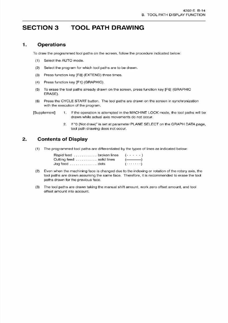
8/15/2019 Okuma Manuals 391
http://slidepdf.com/reader/full/okuma-manuals-391 137/397
4202-E
B-14
B. TOOL PATH DISPLAY FUNCTION
SECTION 3
TOOL PATH
DRAWING
Operations
.
To draw the programmed
tool
paths
on
the
screen,
follow
the
procedure
indicated
below:
(1)
Select
the
AUTO mode.
(2)
Select
the program
for which
tool paths are
to
be
drawn.
(3)
Press function
key
[F8]
(EXTEND)
three
times.
(4) Press
function ke y
[F1]
(GRAPHIC).
(5)
To
erase
the tool paths already drawn on
the
screen, press
function
key
[F6]
(GRAPHIC
ERASE).
(6)
Press
the
CYCLE
START button. The tool
paths
are
drawn on
the screen
in synchronization
with
the
execution of
the
program.
[Supplement]
1
. If the
operation is
attempted
in
the
MACHINE LOCK
mode, the
tool
paths will be
drawn while actual axis movements do not
occur.
2. If “0 (Not
draw)” is set at
parameter
PLANE
SELECT on
the
GRAPH
DATA page,
tool
path
drawing
does not occur.
2.
Contents
of
Display
(1)
The programmed
tool
paths
are differentiated
by the
types
of
lines
as indicated below:
Rapid
feed
.
Cutting
feed
Jog
feed
. . .
(2)
Even when
the machining
face
is changed due
to
the indexing
or rotation
of the
rotary
axis, the
tool paths are drawn
assuming
the
same
face. Therefore, it
is
recommended to erase the tool
paths
drawn
for
the
previous
face.
(3) The tool paths are drawn
taking
the manual shift
amount,
work
zero
offset
amount,
and tool
offset
amount
into
account.
broken lines
solid
lines
dots
( )
(
)
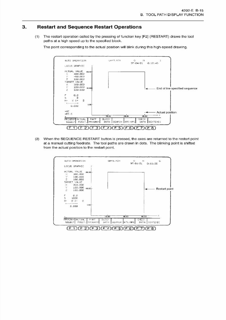
8/15/2019 Okuma Manuals 391
http://slidepdf.com/reader/full/okuma-manuals-391 138/397
4202-E B-15
B. TOOL PATH DISPLAY FUNCTION
3.
Restart
and
Sequence
Restart
Operations
(1)
The
restart
operation
called
by
the pressing
of
function ke y [F2] (RESTART)
draws the tool
paths
at a
high
speed up
to the
specified
block.
Th e point
corresponding
to the actual
position
will
blink
during
this
high-speed drawing.
rjRpa.MTN
0
UTO OPERATION
W
1
97/04ÿ01
0:10:46
LOCUS
GRAPHIC
ACTUAL VALUE
300.003
-50.003
100.000
TARGET
VALUE
300.000
100.000
100.000
m.
HDD
X
Z
A
Y
100. COD
En d of tne
specified sequence
z
F
0.0
0
H= 0 D- 0
Q.OOQ
0.030
-GE
Actual position
=RS 6
K
IDO. ODD 2DD.BDE
3BD.0DU
PROGRAM
ACTUAL FART
BLOCK
SELECT
POSIT.
PROGRAM DATA SEARCH ATC/APC
CHECK
DATA C
EXTEND]
(TT]rrr i rÿ(Txn(TÿrF~ÿrF~7-)rF~B]
(2) When the SEQUENCE
RESTART
button
is
pressed, the axes are returned to
the
restart
point
at
a manual
cutting feedrate.
The tool paths
are
drawn
in
dots.
The blinking point
is shifted
from
the
actual
position
to
the
restart
point.
AUTO
OPERATION GFP3.MIN
0
IN
6
97/04/01 0:11:
EE
LOCUS GRAPHIC
ACTUAL VALUE
300.000
100.000
100.000
TARGET VALUE
300.000
100.000
100.000
sno.Don
V
:
x
Y
m.m
-
Restart point
z
F
0.0
S
1000
H=
0 D=
0
l-POII
0.000
inn.DUD
2an.ncn
m.m
PROGRAM
ACTUAL
PART
BLOCK
SELECT
POSIT'. PROGRAM
DATA
SEARCH
ATC/APC
CHECK
DATA
[EXTENDI
rrrirrT)rÿ(TÿrFÿrF~6TrF~7~)rF~BT

8/15/2019 Okuma Manuals 391
http://slidepdf.com/reader/full/okuma-manuals-391 139/397

8/15/2019 Okuma Manuals 391
http://slidepdf.com/reader/full/okuma-manuals-391 140/397
4202-E
B-1 7
B. TOOL PATH DISPLAY FUNCTION
SECTION 4 PARAMETERS
NO
optional parameter (bit)
No.
33 bi t 0
Effective/ineffective
of
graphic
coordinate
system
0:
Graphic
coordinate
system
is
made
ineffective when
power
supply
is
turned
on or
the
control is
reset.
1 :
Graphic
coordinate
system
is
made
effective when
power supply
is turned
on
or
the control
is
reset.

8/15/2019 Okuma Manuals 391
http://slidepdf.com/reader/full/okuma-manuals-391 141/397

8/15/2019 Okuma Manuals 391
http://slidepdf.com/reader/full/okuma-manuals-391 142/397
4202-E
C-1
C. NC
OPERATION
MONITOR
SECTION
1 OVERVIEW
This
function
has
two
sub
functions as
N C H OU R
METER
and NC WORK
COUNTER.
The
NC HOUR
METER
function:
Accumulates
the
following
hours and
displays
them on the
screen.
P OW ER O N
TIME
NC RUNNING
TIME
SPINDLE REVOLUTION
TIME
CUTTING
TIME
EXTERNAL
INPUT
TIME
The
NC WORK C OUN TER function: Has four work
counters
an d
counter
data
of individual
counters
is
displayed
on the screen. These four counters can be
used
as
required.
In addition,
data
can be
preset
for each t imer and counter. When
the COUNT
dataexceeds
the
SE T
value,
alarm
signal
is
output.

8/15/2019 Okuma Manuals 391
http://slidepdf.com/reader/full/okuma-manuals-391 143/397
4202 -E C-2
C. NC OPERATION MONITOR
SECTION 2
NC
HOUR
METER
Contents
of
Display.
Press
function
ke y
[F6]
(ITEM
f)
or
[F7]
(ITEM
1)
after selecting the PARAMETER SET
mode,
then the NC
HOUR
METER screen will be
displayed.
I
PARAMETER SET
97/07/15
14:f0l00
*
NC
HOUR
METER
*
COUNT
SET
99999
:
59:59
0
:
0: 0
1
;«s
0
:
0
:
0
22222
:
22
:
22
99999
:
59
:
59
0
:
0
:
0
1.
POWER
ON
TIME
2.
NC
RUNNING TIME
3.
SPINDLE REVOLUTION
TIME
4.
CUTTING
TIME
5.
EXTERNAL
INPUT
TIME
Y Z
B
AC T POSIT
(WORK)
2288.000 2288.000 240.000
0.000
ITEM
t
[EXTEND]
EARCH
ITEM
]
ET
ADD
(T~F1
fTTH
rF~ÿ~|
fF~6l
fF~7ÿ
f?~Bl
Details
of
the
display
contents
are
explained
below:
The units of
displayed
data
are “hours:minutes:seconds”.
(1)
POWER ON
TIME
This accumulates duration of time
in
which
power supply
to the NC is
on .
(2)
NC
RUNNING
TIME
This
accumulates duration of
time
in
which NC
is
operating.
Note
that
operation
time
in
the
machine
lock
mode is
not
accumulated.
(3) SPINDLE
REVOLUTION
TIME
This
accumulates
duration of
time
in
which
the
spindle
has
been
rotat ing. However,
the time in
which
the
control
is
placed
in
the machine
lock
mode is
not
accumulated
since the
spindle
is
not
rotating in
this mode.
(4)
CUTTING
TIME
This accumulates duration of
time
in
which
axes are
fed in cutting
feedrates.
However,
the time
in
which the control is p laced in
the
machine
lock
mode
is
not accumulated.
(5)
EXTERNAL
INPUT
TIME
This accumulates duration of
time
in which
the
external
input
signal
is ON.
8/15/2019 Okuma Manuals 391
http://slidepdf.com/reader/full/okuma-manuals-391 144/397
4202-E C-3
C. NC OPERATION MONITOR
2.
Count
Data
and
Set Data
(1)
Setting
of
both
the COUNT
(accumulated)
and SET
(not accumulated)
data is
possible
by
locating
the cursor
at
the
required
data
position.
(2)
If
the
COUNT
data exceeds the value
set
at
SET,
alarm
signal
is
output.
(3)
When
output
of the alarm
signal
is not
required,
set
“0:0:0”
at the SET column.
(4)
The
maximum
setting
values for both COUNT and
SET are
99999:59:59.
(5)
Setting format is
“hours:minutes:seconds” and omission
is not al lowed.
Example:
S
0:28:59
Be sure to
place
a colon.
3. Alarm
If
any
on e of
the COUNT
values exceeds
the SE T
value,
the following
alarm
occurs and
cycle
start of
the NC is
disabled.
3239
ALARM-C
Running
hour over
X
[Index] None
[Character-string]
None
[Code]
X= 1 Alarm with power on time
timer
Alarm with
NC
on
time
timer
Alarm
with
spindle on time t imer
Alarm with cutting time timer
Alarm
with
external
input
time
t imer
2
3
4
5
To reset the
alarm,
(1)
Set COUNT value smaller than SET value.
(2)
Set
SET
value
larger than COUNT value.
(3)
Set
SET
value
at 0:0:0.
Reset
the
NC
after
taking
any
of
the
above indicated
measures.
Note that simple NC reset
operation
cannot reset this alarm.
Note:
if
measure
3
is
taken,
alarm check
is
not conducted.
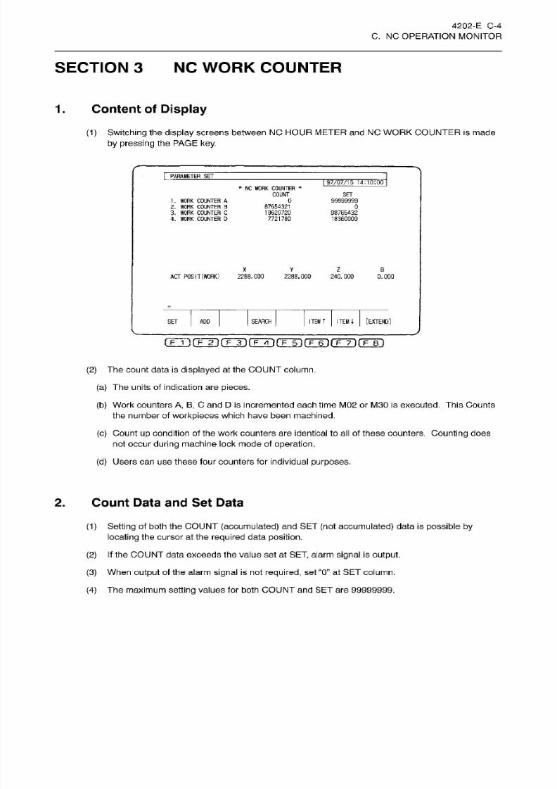
8/15/2019 Okuma Manuals 391
http://slidepdf.com/reader/full/okuma-manuals-391 145/397
4202 -E C-4
C. NC OPERATION MONITOR
SECTION 3
NC
WORK COUNTER
1.
Content of
Display
(1)
Switching
the display
screens between NC HOUR
METER
and NC WORK COUNTER is made
by
pressing
the
PAGE
key.
PARAMETER
SET
I
97/07/15
14:10:00
*
NC
WORK
COUNTER
*
COUNT
SET
0
99999999
. WORK
COUNTER
A
2.
WORK COUNTER
B
3. WORK
COUNTER
C
4. WORK COUNTER D
87654321
19620720
7721780
0
98765432
18360000
X
Z
B
AC T
POSIT
(WORK)
2288.000 2288.000 240.000
0.000
ITEM
t
ITEM
i
[EXTEND]
EARCH
ET
AD D
(TlirFTÿ('TT1(TTÿ(TÿfFÿfF~T)fF~Bl
(2)
The count data is
displayed at
the
COUNT
column.
(a) The
units
of indication are pieces.
(b) Work counters
A,
B,
C and D is incremented
each time M02 or M30 is
executed.
This
Counts
the number of
workpieces
which have been machined.
(c)
Count up condition
of the
work counters are
identical to al l of these
counters. Counting does
not occur
during
machine lock mode of
operation.
(d)
Users
ca n us e these
four
counters for individual
purposes.
2.
Count
Data and Set
Data
(1 )
Setting
of both the COUNT
(accumulated)
and
SET
(not
accumulated)
data is
possible
by
locating
the cursor
at
the
required
data
position.
(2 )
If
the COUNT data exceeds the value set at
SET,
alarm
signal
is
output.
(3)
When
output of
the
alarm
signal
is not
required,
set
“0 ” at
SE T column.
(4)
The maximum setting values for both
COUNT
and
SE T are 99999999.
8/15/2019 Okuma Manuals 391
http://slidepdf.com/reader/full/okuma-manuals-391 146/397
4202-E
C-5
C. NC
OPERATION
MONITOR
3. Alarm
If an y
one of
the
COUNT
values exceeds
the SET
value,
the
following
alarm occurs and
cycle
start
of
the
NC
is disabled.
Work counter over240
The active
work
counter data has exceeded the full
count value.
[Code]
X
=
1
Alarm
with work
counter
A
Alarm
with
work counter
B
Alarm with work counter
C
Alarm with work
counter
D
2
3
4
[Measures
to
Take]
1)
Designate
a count value which
is
smaller than the
setting
value.
2) Designate
a
setting
value
which
is
larger
than the count
value.
3) Designate
a
setting
of
“0”.
To
reset
the
alarm,
(1)
Se t
COUNT
value
smaller
than
SE T value.
(2) Se t
SET
value
larger than COUNT
value.
(3)
Set SET value at
0.
Reset
the
NC
after
taking
any of the above
indicated
measures.
Note
that s imple NC reset operation
cannot reset
this
alarm.
Note:
ff
measure
3
is
taken,
alarm check is not conducted.

8/15/2019 Okuma Manuals 391
http://slidepdf.com/reader/full/okuma-manuals-391 147/397
D.
Hi2-NC FUNCTION
(HIGH-SPEED NC)
8/15/2019 Okuma Manuals 391
http://slidepdf.com/reader/full/okuma-manuals-391 148/397
4202-E
D-1
D.
Hi2-NC
FUNCTION
(HIGH-SPEED
NC)
SECTION
1
OVERVIEW
(1)
Th e Hi2-NC function
consists
of the
following
functions:
(a)
High-speed
NC
interpolation
function
which
makes
high
cutting
feedrate for continuous minute
motion blocks
possible.
(b)
Quick response,
high-accuracy
servo
function and tolerance control function which
ensure
high
machining accuracy
on
sculptured surface and
edges.
(2)
The
high-speed
NC
interpolation
function allows
high
cutting feedrate for
cutting
sculptured
surface.
(3)
The
part
program
used
to cut sculptured surface
consists
of
continuous minute
motion blocks
which are created
by
dividing
the sculptured
surface
into
proper
segments
and arcs. The
high-speed
NC
interpolation
function has the
capability
to
read these
minute motion command
blocks and
carries
out
interpolation
at a high speed
to
provide improved high
cutting
feedrate.
The
quick
response, high
accuracy servo
function
and
the
tolerance
control function
greatly
improve
the machined
shape accuracy on
sculptured
surface and
edges. Especially,
the
tolerance
control
function controls
axis feedrates so that the error
on
the machined
shape
is
always
limited within
the
designated
tolerance
while
cutting
sculptured
surface
and edges
at
a
high speed.
With
this
function,
consistently high machining accuracy
is
ensured.
(4)

8/15/2019 Okuma Manuals 391
http://slidepdf.com/reader/full/okuma-manuals-391 149/397
4202-E
D-2
D.
Hi2-NC
FUNCTION
(HIGH-SPEED
NC)
SECTION 2 HIGH-SPEED
NC
INTERPOLATION
FUNCTION
(1)
Th e
high-speed
NC interpolation function
is
developed
by
increasing
the NC interpolation speed
of
the
NC
itse lf . This
means
that;
(a)
high
cutting
feedrate for
continuous minute motion
blocks
is
achieved
using
the
same
program
format
as applied
for conventional
programs,
and
(b)
the same
NC
operations,
such as the sequence
restart,
manual intervention, etc.,
as
available
with the
conventional NC
can be used.
(2)
The high-speed
NC
function reads
more than 9 blocks of commands into the buffer
automatically
when minute motion
blocks
are continued
in
the
part program
so
that the stable
high-speed
NC
interpolation
is
possible.
8/15/2019 Okuma Manuals 391
http://slidepdf.com/reader/full/okuma-manuals-391 150/397
4202-E
D-3
D.
Hi2-NC
FUNCTION
(HIGH-SPEED
NC)
SECTION 3 TOLERANCE CONTROL FUNCTION
The tolerance control
function
guarantees machining
accuracy for any
type
of
workpiece shape
by
the ‘‘automatic control
of
cutting
feedrate
meeting
the
shape being
machined”,
the
technology
realized
on
the
base
of
quick-response,
high-accuracy
servo
function.
To obtain
required
accuracy,
only
the
designation
of allowable
tolerance is necessary in the
program.
Modification
of
feedrates
corresponding to
the
shape to
be cut
is not necessary any
more.
(1)
(2)
(3)
By designating
the upper
limit
of
the cutting
feedrate,
which
is
determined
according to cutting
conditions
(workpiece
material,
tool
type,
spindle speed, etc.), the maximum
value
of
feedrate
is
clamped
at this upper
limit.
Therefore,
automatic feedrate
control
which meets the
cutting
conditions
is enabled.
(4)
Furthermore,
the
tolerance control
function
‘‘automatically
determines
the
optimum servo control
parameters
best
fitting
to
cutting” based
on
the
upper
limit
of
feedrate which
is
determined
according
to the
cutting
conditions.
Therefore, high-speed, high-accuracy machining
is
always
possible regardless
of
cutting
conditions.
Because automatic
cutting
feedrate control
in
the tolerance control
function
is carried out while
actual
tool
position
is
monitored, machining
accuracy
is
consistently high.
In addit ion,
the
consistently high
accuracy
machining
is realized
in high
feedrates
through
the
feed forward
control which
secures
the
machining accuracy
without
lowering
feedrates
excessively,.
(5)
1.
Designating
Tolerance
Control
Mode
To turn
on
the
tolerance
control
function, designate
the “TOLERANCE
CONTROL ON”.
(1
)
Set
the
following
tolerance control
parameters
according
to the
type
of
machining:
(a)
CONTROL AXIS
(b) HIGH-SPEED MODE
(c) MAXIMUM FEEDRATE
(d) WORK TOLERANCE
(e) FILTER
VALUE
(f)
FILTER MODE
(g)
SMOOTHING MODE
(h)
SMOOTHING
LENGTH
(i)
SMOOTHING
FILTER
VALUE
(2)
Designation
of the tolerance control mode
is
made
in the
following two methods:
(a)
Parameter setting
(b)
Program
command

8/15/2019 Okuma Manuals 391
http://slidepdf.com/reader/full/okuma-manuals-391 151/397
4202-E
D-4
D.
Hi2-NC
FUNCTION
(HIGH-SPEED
NC)
(3) The tolerance control is effective
only
to the
cutting
feed commands
in
the “feed per minutes”
mode
programmed in
the
tolerance control
mode.
In
other
words,
the tolerance
control
is not
effective to the
rapid
feed commands and
the
feed/rev.
commands
programmed in
the tolerance
control mode.
(4)
Concerning
the
axes,
the
tolerance control is effective
only
to
the
basic three
axes
(X ,
Y,
Z)
and
their
parallel
axes
(U,
V,
W).
Fo r
the
rotating
axes
(A,
B,
C),
the tolerance control
is not
effective.
2.
Tolerance
Control
Parameters
(1)
CONTROL
AXIS
(a)
This
parameter selects
the
axes
for which the tolerance control is
made
effective.
(b)
Selection
of the
axis names
is possible between
the
basic
axes
(X, Y, Z) and
linear additional
axes (U,
V,
W).
That
is,
theaxis
names can
be
selected
for
each
Cartesian
coordinate
system
axis
independently:
-
X
direction:
X (basic)
/
U
(additional)
-
Y direction: Y (basic)
/V
(additional)
-
Z
direction:
Z
(basic)
/
W (additional)
(2)
HIGH-SPEED MODE
(a)
The tolerance control function
provides
the following
four control modes and
it
is
possible
to
select
any
of
these modes
to
carry out machining.
-
Normal mode
-
High-speed
mode
1
-
High-speed mode 2
-
High-speed
mode
3
(b) With the tolerance control
function, feedrates are
automatically
controlled
by
the combination
of
the
closed loop
control,
in
which
consistently high accuracy is
secured
for any
workpiece
shape, and
the feed forward control,
in
which
high
accuracy is
secured
without lowering
feedrates
excessively by
estimating machining
error
in
advance.
The feed forward
control,
due to its characteristic that
it
estimates
machining
error
in
advance,
an
error
greater
than
the
preset
tolerance
might be
generated
if slide
hold or other
operation
is
attempted, (positioning
error
in
this
case)
(c)
Therefore,
the
tolerance control
function
permits
the
selection of
control
mode
so
that
the
control best fitting
to
user’s
requirements
is selected between the normal mode, which does
not
include
the feed
forward
control,
and the high-speed
mode,
which
includes the feed
forward control to allow
high-speed cutting.
(d)
The features
of the
high-speed
mode
are
briefly stated
below:
1)
Cutting
time
Cutting
time differs
as
shown below
according
to the selection of the control mode.
Normal mode
>
High-speed
mode 1
>
High-speed
mode
2
>
High-speed
mode 3
8/15/2019 Okuma Manuals 391
http://slidepdf.com/reader/full/okuma-manuals-391 152/397
4202-E D-5
D.
Hi2-NC
FUNCTION
(HIGH-SPEED
NC)
2)
Cutting accuracy
During
normal
cutting
In
the
high-speed
mode 1,
high-speed
mode
2 and high-speed
mode
3,
workpiece
is
finished
within
the set
tolerance
as in the
normal mode.
Slide
hold
button is
pressed
during
cutting
Positioning
error
as
indicated below is
generated
when
cutting
is
being
carried
ou t on curved
surface with small
curvature.
Positioning
error is not
generated.
High-speed
mode
1 . . .
Less than
the
set
tolerance
High-speed mode 2
. . .
Less than
3 t imes the
set
tolerance
High-speed mode
3
. . .
Less than
5
times
the
set tolerance
(3)
MAXIMUM
FEEDRATE
(a)
Feedrate upper limit sets the maximum value of feedrate which is applicable when
cutting
is
carried
out
using
the
tolerance control.
Feedrate
upper limit
=
Maximum value of feedrate command
Normal mode
(b) Because the tolerance control function determines
automatically
the
optimum
servo control
parameters using
the feedrate
upper
limit
value,
consistently
high
accuracy
with
high
speed
is
guaranteed
for
any type
of
machining. Therefore,
if
the
maximum
feedrate
changes
due
to
the
change
in the
type
of machining,
it
is
recommended
to
change the
setting
for
this
parameter.
(c) The
maximum
value of feedrate
designated
in
“per
minute
mode
is
limited
by
this
value.
(4)
WORK TOLERANCE
(a) This
parameter
sets the allowable
machining
error when
the workpiece
is machined
using
the
tolerance control
function.
Tolerance
=
Allowable
machining
error
By
setting
this
parameter,
the
workpiece
is finished within
allowable
error.
(b)
Because
the
tolerance control
function controls
cutting
feedrate
based
on
the
set
tolerance, it
is
recommended to
set
a
large
value
within
allowable
error
so that a
workpiece
is
machined
by
high
feedrates.
Due to the control characteristic that diameter reduction
in
arc
cutting
and
dulling
at corners
will
become
greater
as
higher
feedrate
is
used,
although
smaller tolerance
reduces error,
feedrate
is
lowered at
the same
elongating
total
cutting
time.
When
cutting
free-formed
curve,
which is
approximated
with minute motion blocks of line and arc
command
(programmed
shape):
0)
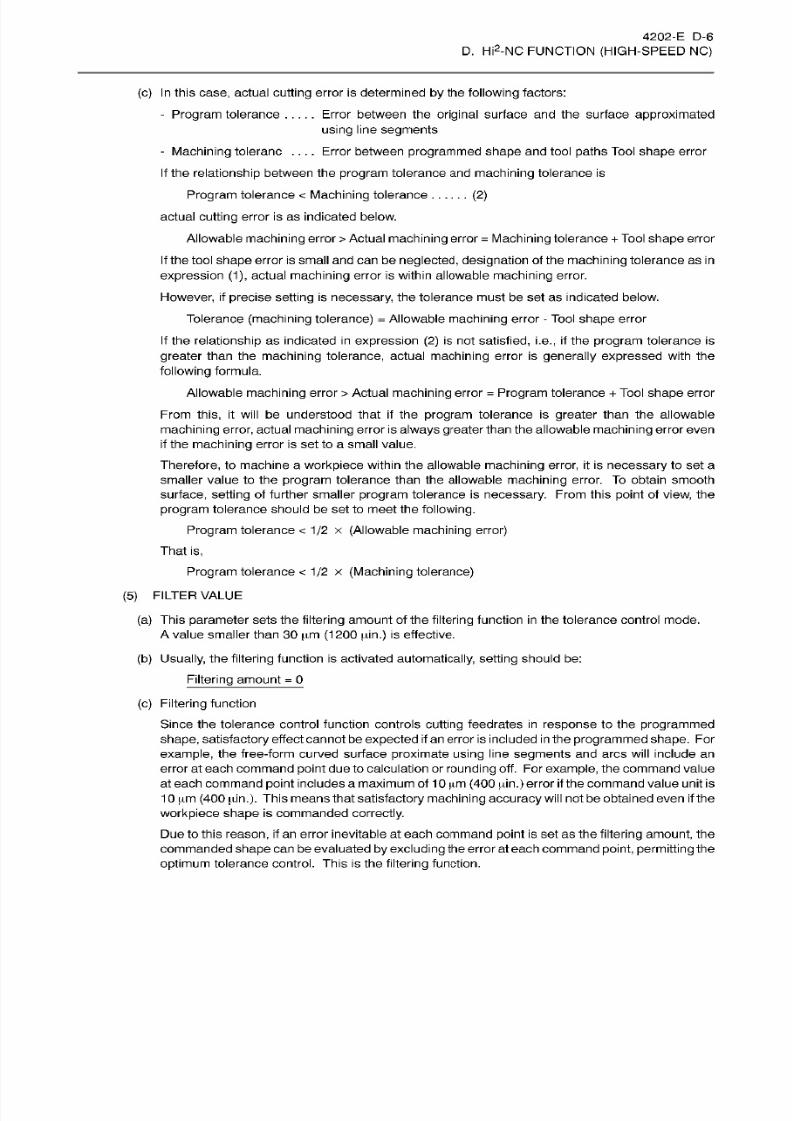
8/15/2019 Okuma Manuals 391
http://slidepdf.com/reader/full/okuma-manuals-391 153/397
4202-E D-6
D.
Hi2-NC
FUNCTION
(HIGH-SPEED
NC)
(c)
In this
case, actual
cutting
error is determined
by
the
following
factors:
- Program
tolerance
.....
rror
between the
original
surface and the surface approximated
using
line
segments
-
Machining
toleranc
....
Error between
programmed
shape
and tool
paths
Tool
shape
error
If
the
relationship
between
the
program
tolerance and
machining
tolerance
is
Program
tolerance
<
Machining
tolerance
(2)
actual
cutting
error is
as
indicated below.
Allowable
machining
error
>
Actual
machining
error
=
Machining
tolerance
+
Tool
shape
error
If
the tool
shape
error
is
small
and
can
be
neglected, designation
of
the
machining
tolerance
as
in
expression
(1), actual machining error is
within
allowable machining
error.
However,
if
precise
setting is
necessary,
the
tolerance
must
be set
as
indicated
below.
Tolerance
(machining
tolerance)
=
Allowable machining
error -
Tool shape
error
If
the relationship as indicated
in
expression
(2)
is
not
satisfied,
i.e.,
if
the
program
tolerance
is
greater than
the
machining
tolerance, actual
machining
error
is
generally
expressed with the
following formula.
Allowable
machining
error
>
Actual
machining
error
=
Program
tolerance
+
Tool
shape error
From this,
it
will
be understood that
if
the program tolerance is
greater
than the allowable
machining error, actual machining
error
is always greater
than
the
allowable
machining
error
even
if the machining
error is
set
to a
small value.
Therefore,
to machine a
workpiece
within
the
allowable
machining error,
it is
necessary
to set a
smaller value
to
the program
tolerance
than
the
allowable
machining
error. To
obtain smooth
surface,
setting
of further smaller
program
tolerance is
necessary.
From this
point
of view, the
program
tolerance should
be
set
to meet
the
following.
Program
tolerance
<
1/2
x
(Allowable
machining
error)
That
is,
Program
tolerance
<
1/2
x
(Machining tolerance)
(5)
FILTER
VALUE
(a)
This
parameter
sets the
filtering
amount of the
filtering
function
in
the tolerance control mode.
A
value smaller than 30
|im
(1200
pin.) is effective.
(b)
Usually, the filtering function
is
activated automatically,
setting
should be :
Filtering
amount
=
0
(c) Filtering
function
Since
the tolerance
control function
controls
cutting
feedrates
in
response
to
the
programmed
shape,
satisfactory
effect cannot be
expected
if an error
is
included in the
programmed shape.
For
example,
the
tree-form curved surface
proximate
using
line
segments
and
arcs
will
include
an
error
at
each
command
point due
to calculation or
rounding
off.
For
example,
the
command
value
at each command
point
includes
a
maximum
of 1
0
pm
(400 pdn.)
error if the command value unit
is
1
0 urn (400 pin.). This means
that
satisfactory
machining accuracy will
not be obtained
even if
the
workpiece shape
is
commanded
correctly.
Due to this
reason,
if
an error inevitable at
each
command
point
is set
as
the
filtering amount,
the
commanded
shape
can be evaluated
by excluding
the
error
at
each
command
point, permitting
the
optimum
tolerance control.
This
is
the filtering function.
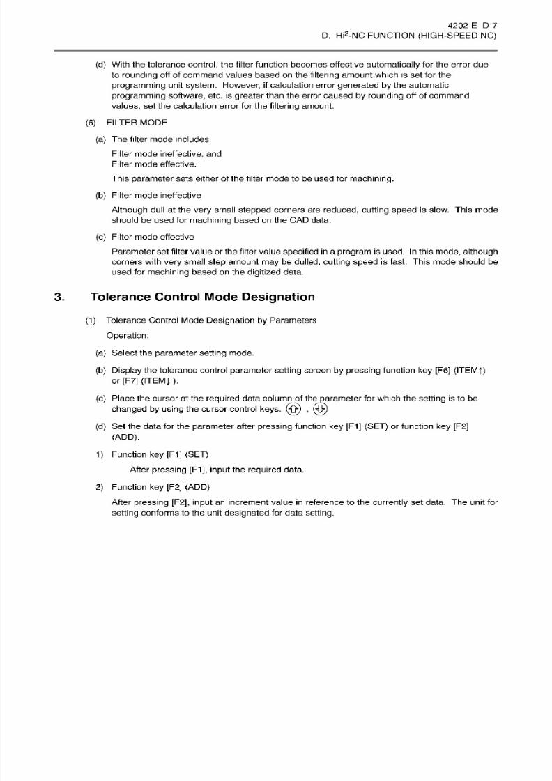
8/15/2019 Okuma Manuals 391
http://slidepdf.com/reader/full/okuma-manuals-391 154/397
4202-E
D-7
D.
Hi2-NC
FUNCTION
(HIGH-SPEED
NC)
(d)
With the tolerance control, the
filter
function becomes
effective automatically
for the error due
to rounding off of command values based
on
the filtering
amount which
is set
for
the
programming
unit
system.
However,
if calculation
error
generated by
the automatic
programming
software, etc. is
greater
than
the error caused
by rounding
off
of
command
values,
set the calculation error for the
filtering amount.
(6)
FILTER
MODE
(a)
The filter mode includes
Filter mode
ineffective, and
Fil ter mode
effective.
This
parameter
sets either of the filter mode to be used for
machining.
(b)
Filter mode
ineffective
Although
dull at the
very
small
stepped
corners
are
reduced,
cutting
speed
is slow.
This
mode
should be
used
for
machining
based
on
the CAD data.
(c)
Filter mode
effective
Parameter
set filter value or
the filter
value
specified
in
a
program
is
used.
In
this
mode, although
corners with
very
small
step
amount
may
be
dulled, cutting speed
is fast. This mode should be
used
for
machining
based
on
the
digitized
data.
3. Tolerance
Control
Mode Designation
(1 ) Tolerance Control Mode
Designation by
Parameters
Operation:
(a)
Select
the
parameter
setting mode.
(b)
Display
the
tolerance control
parameter
setting
screen
by pressing
function
key
[F6]
(ITEMf)
or [F7]
(ITEMj ).
(c)
Place
the
cursor at the
required data column
of
theparameter
for
which
the setting is to
be
changed
by using
the cursor control
keys.
(ÿ)
,
(d)
Set the data for
the
parameter after
pressing
function
key [F1] (SET)
or function
key
[F2]
(ADD).
1) Function
ke y
[F1]
(SET)
After
pressing
[F1],
input
the
required data.
2)
Function
key
[F2]
(ADD)
After
pressing
[F2], input
an
increment
value
in
reference to
the
currently
se t
da ta. T he
unit for
setting
conforms
to
the
unit designated
for data setting.
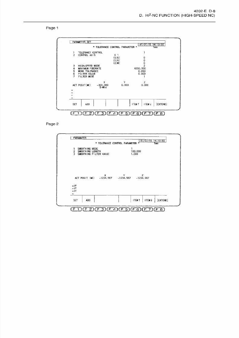
8/15/2019 Okuma Manuals 391
http://slidepdf.com/reader/full/okuma-manuals-391 155/397
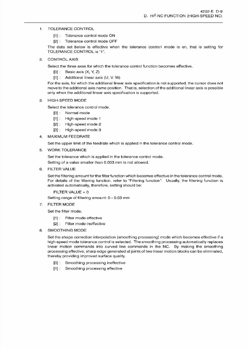
8/15/2019 Okuma Manuals 391
http://slidepdf.com/reader/full/okuma-manuals-391 156/397
4202-E D-9
D.
Hi2-NC
FUNCTION
(HIGH-SPEED
NC)
1 .
TOLERANCE CONTROL
[1]
:
Tolerance control mode ON
[2]
:
Tolerance
control
mode
OFF
The data
set
below is
effective
when the tolerance control m ode is
on ,
that
is
setting
for
TOLERANCE
CONTROL
is
“1”.
2.
CONTROL
AXIS
Select the
three
axes for
which
the tolerance control
function
becomes effective.
[0] :
Basic
axis (X,
Y,
Z)
[1]
:
Additional
linear
axis
(U,
V.
W)
For the axis, for which the additional linear axis
specification
is not
supported,
the
cursor does not
move
to the additional
axis name
position.
That
is,
selection of the
additional
linear
axis
is
possible
only
when the additional
linear
axis
specification
is
supported.
3.
HIGH-SPEED
MODE
Select the tolerance control mode.
[0]
:
Normal mode
[1]:
High-speed mode 1
[2]
: High-speed
mode
2
[3] :
High-speed
mode
3
4.
MAXIMUM FEEDRATE
Set the upper limit of the feedrate which is
applied
in
the
tolerance
control mode.
5.
WORK TOLERANCE
Set the
tolerance
which is
applied
in
the tolerance control
mode.
Setting
of
a
value
smaller
than 0.003
mm
is
not
allowed.
6.
FILTER
VALUE
Se t the
filtering
amount for
the filter
function which
becomes effective in the tolerance control
mode.
Fo r details of the filtering
function,
refer to “Filtering
function”.
Usually, the filtering function
is
activated automatically, therefore,
setting
should
be :
FILTER
VALUE
=
0
Setting
range of
filtering
amount:
0
-
0.03 mm
7. FILTER
MODE
Set
the filter
mode.
[1]:
Filter
mode
effective
[2]
:
Filter
mode
ineffective
8.
SMOOTHING MODE
Set
the
shape
correction
interpolation (smoothing processing)
mode which
becomes
effective
if
a
high-speed
mode tolerance control
is
selected.
The
smoothing
processing
automatically
replaces
linear motion
commands
into
curved
line commands
in
the
NC.
By
making
the
smoothing
processing
effective, sharp
edge generated at joints
of two
linear motion
blocks
can
be
eliminated,
thereby providing
improved
surface
quality.
[0] :
Smoothing processing
ineffective
[1]
:
Smoothing
processing
effective
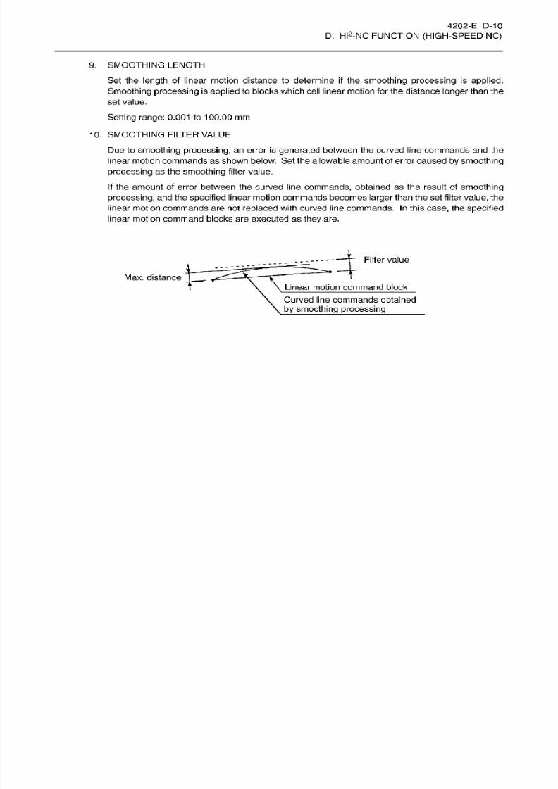
8/15/2019 Okuma Manuals 391
http://slidepdf.com/reader/full/okuma-manuals-391 157/397
4202-E D-10
D.
Hi2-NC
FUNCTION
(HIGH-SPEED
NC)
9.
SMOOTHING
LENGTH
Set the
length
of linear motion distance to determine
if
the
smoothing processing
is applied.
Smoothing processing
is
applied
to blocks which call
linear
motion for
the
distance
longer
than
the
set
value.
Setting
range:
0.001
to
100.00
mm
10.
SMOOTHING
FILTER
VALUE
Due
to
smoothing processing,
an error is
generated
between the
curved l ine commands
and
the
linear motion commands
as
shown below. Set
the
allowable amount of error
caused
by
smoothing
processing as the smoothing
filter value.
If the amount
of error
between the
curved
line commands,
obtained as
the resul t
of
smoothing
processing,
and the
specified
linear
motion
commandsbecomes
larger than
the
set filter value, the
linear motion commands
are not
replaced
with curved line commands.
In
this
case,
the
specified
linear
motion command blocks are executed
as
they
are.
Filter
value
1=
ax.
distance
Linear
motion command
block
Curved
line
commands obtained
by smoothing processing_
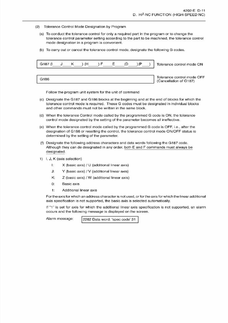
8/15/2019 Okuma Manuals 391
http://slidepdf.com/reader/full/okuma-manuals-391 158/397
4202-E
D-11
D.
Hi2-NC
FUNCTION
(HIGH-SPEED
NC)
(2) Tolerance Control Mode
Designation
by
Program
(a) To conduct the tolerance control for
only
a
required
part in
the
program
or to
change
the
tolerance control
parameter
setting according
to the
part
to be
machined,
the tolerance control
mode
designation in
a
program
is convenient.
(b)
To
carry
out
or
cancel the tolerance control
mode, designate
the
following
G
codes.
G187
(I
_
J
_
K
_
)
(H
_
)
F
_
E
_
(D
_
)(P
_
)
Tolerance
control mode
ON
Tolerance control mode
OFF
(Cancellation
of
G187)
186
Follow the
program
unit
system
for
the unit o f command
(c)
Designate
the
G187
an d
G186
blocks
at
the
beginning
and at the end
of
blocks
for
which the
tolerance control mode
is
required.
These
G codes must be
designated in
individual blocks
and
other
commands must not be written
in
the same block.
(d)
When the tolerance Control mode called
by
the
programmed
G code is
ON,
the tolerance
control mode
designated by
the
setting
of the
parameter
becomes
all ineffective.
(e)
When the tolerance control mode called
by
the
programmed
G code
is
OFF,
i.e.,
after the
designation
of
G186 or
resetting
the
control,
the
tolerance control
mode
ON/OFF
status is
determined
by
the
setting
of the
parameter.
(f) Designate
the
following
address characters and data words
following
the
G187
code.
Although they
ca n
de
designated in
any
order,
both
E
and
F
commands
must
always
be
designated.
1)
I,
J,
K (a xis
selection)
I:
X (basic axis)
/
U
(additional
linear
axis)
J:
Y (basic axis)
/
V
(additional
linear
axis)
K: Z
(basic axis)
/
W (additional
linear
axis)
0: Basic
axis
1
:
Additional
l inear axis
For the
axis for
which
an
address character is
not
used,
or
for
the
axis
for whichthe
linear
additional
axis specification is
not
supported,
the basic axis is
selected
automatically.
If
“1” is
set
fo r axis fo r
which
the additional linear axis specif ication is
not supported,
an alarm
occurs an d the
following message
is
displayed
on the screen.
Alarm
message:
2262 Data word:
‘spec
code’ 31
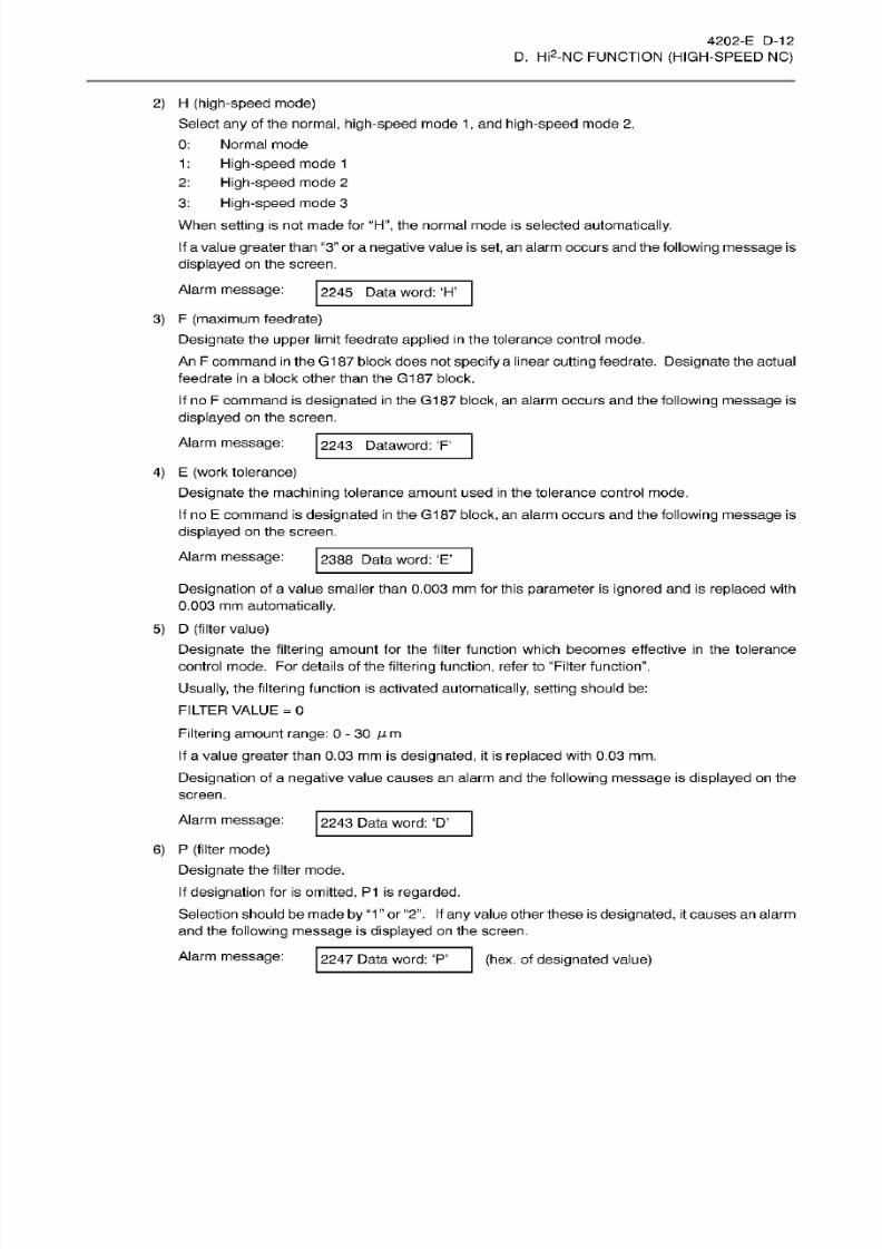
8/15/2019 Okuma Manuals 391
http://slidepdf.com/reader/full/okuma-manuals-391 159/397
4202-E
D-12
D.
Hi2-NC
FUNCTION
(HIGH-SPEED
NC)
2)
H (high-speed
mode)
Select any
of the
normal, high-speed mode 1
, and
high-speed
mode
2.
0:
Normal mode
1: High-speed
mode
1
2:
High-speed
mode
2
3:
High-speed
mode
3
When setting is not
made
for
“H”,
the
normal mode is selected
automatically.
If
a
value greater
than “3” or a
negative
value
is
set,
an
alarm
occurs
and the
following message is
displayed
on the screen.
Alarm
message:
2245 Data word:
‘H’
3)
F
(maximum
feedrate)
Designate
the upper limit feedrate
applied
in
the
tolerance control
mode.
An
F
command
in
the
G187 block
does
not
specify
a
linear
cutting
feedrate.
Designate
the actual
feedrate
in a
block
other
than
the
G187
block.
If
no
F
command
is
designated
in the
G187
block, an
alarm
occurs and
the
following message is
displayed on
the screen.
Alarm
message:
2243
Dataword:
'F'
4)
E
(work
tolerance)
Designate
the
machining
tolerance amount used
in
the tolerance control mode.
If
no
E
command is
designated
in the G1
87
block,
an
alarm
occurs
an d
the
following
message
is
displayed
on
the
screen.
Alarm
message:
2388 Data
word:
‘E’
Designation
of
a
value smaller than 0.003 mm for this
parameter is ignored
and is replaced with
0.003
mm automatically.
5)
D
(filter
value)
Designate
the filtering
amount
for the f il ter function which becomes effective
in
the tolerance
control m ode. F or details of
the filtering function,
refer to “Filter function”.
Usually,
the
filtering
function
is
activated
automatically,
setting should be:
FILTER
VALUE
=
0
Filtering
amount
range:
0-30
Aim
If a
value
greater
than 0.03
mm is designated, it
is replaced with 0.03
mm.
Designation
of a
negative
value
causes an
a la rm and the
following message
is
displayed
on the
screen.
Alarm
message:
2243 Data word:
‘D ’
6)
P
(filter
mode)
Designate
the filter
mode.
If
designation
for is omitted,
P1 is regarded.
Selection
should
be
made
by “1
” or
“2”. If
any
value other
these
is
designated,
it causes
an
alarm
and the
following
message
is
displayed
on
the
screen.
Alarm message:
2247
Data
word:
‘P’
(hex.
of
designated
value)

8/15/2019 Okuma Manuals 391
http://slidepdf.com/reader/full/okuma-manuals-391 160/397
4202-E D-13
D.
Hi2-NC
FUNCTION
(HIGH-SPEED
NC)
4.
Tolerance Control
Guide
In
the
Check Data
pages
accessible
in
the
automatic
operation
mode,
the TOLERANCE
CONTROL
GUIDE
page
is
contained.
Using
this
display
page,
the tolerance control
setting
and state
can
be monitored.
To
display
the
TOLERANCE
CONTROL GUIDE
page,
follow the
any
of the
procedure
indicated below:
(1)
After
pressing
function
key
[F7]
(CHECK
DATA),
press
the
PAGE
ke y
repeatedly
until
the
TOLERANCE
CONTROL GUIDE
page is
displayed.
(2)
Press function
key
[F5] (SEARCH)
and
the
WRITE
key
to
display
the CHECK
DATA
DIRECTORY page. Using this page, key in the
number
corresponding
to
the
TOLERANCE
CONTROL GUIDE
page
to
directly display
the
required
page.
AUTO
OPERATION TEST.
MIN
0100
N2148
38
’
97/07/1
5 14:10:00
*
TOLERANCE GUIDE
*
PAGE
78
1mm
TOLERANCE
CONTROL
EXECUTE
PROGRAM
G
1
8 7
I
J
K
PARAMETER
TOLERANCE CONTROL
CONTROL AXIS
HIGH-SPEED MODE
M A X IM U M F E E DR A T E
WORK TOLERANCE
FILTER
VALUE
FILTER
MODE
CONDITION
EXIST
(X
Y
Z)
0
F
6000.
000
0.010
0.010
E
D
p
1
S-Mtd
ACTUAL
PART
BLOCK
POSIT.
I
PROGRAM
I
DATA
PROGRAM
SELECT
CHECK
[EXTEND]
SEARCH
DATA
(Tji(Tÿ(Tÿ(TÿrFT)frÿrFÿrrr)
8/15/2019 Okuma Manuals 391
http://slidepdf.com/reader/full/okuma-manuals-391 161/397
4202-E
D-14
D. Hi2-NC
FUNCTION
(HIGH-SPEED
NC)
1
.
TOLERANCE CONTROL
NONE E XE CUTE Indicates that the
tolerance control
is
not
effective.
Indicates that the tolerance control
is
effective.XECUTE
2.
PROGRAM,
PARAMETER
Indicates which
of
the
settings
is
effective
to
activate
the
tolerance
control; currently
used
setting
is
indicated
by
the reverse
display.
3. G187
TOLERANCE
CONTROL
Indicates the current tolerance mode
on/off
state.
OFF The tolerance control mode
is
off.
ON The tolerance
control
mode
is
on.
The
following
data
is effective
only when the
tolerance
control mode
is
on.
4.
UK CONTROL AXIS
Indicates the three axes
for which the
tolerance control mode is
effective.
5.
H HIGH-SPEED MODE
Indicates
the
currently effective high-speed
mode.
‘0’
Normal mode
T
High
speed
No.
1 mode
‘2’
High
speed
No .
2
mode
'3 '
High
speed
No . 3
mode
6.
F
MAXIMUM FEEDRATE
Indicates
the currently
effective
maximum
feedrate.
7.
E
WORK TOLERANCE
Indicates the
currently
effective
machining
tolerance amount.
8.
D FILTER
VALUE
Indicates the currently effective
filtering
amount.
9.
P
FILTER
MODE
Indicates the currently selected
filter
mode.
'
1
’
Filter mode
effective
‘2’
Filter
mode
ineffective
8/15/2019 Okuma Manuals 391
http://slidepdf.com/reader/full/okuma-manuals-391 162/397
4202-E D-15
D.
Hi2-NC
FUNCTION
(HIGH-SPEED
NC)
5. Alarm
Alarm A
1
266 Tolerance
control error
The
tolerance control could
not
be
executed due
to
an
error
in
the NC control software processing.
Note: This alarm
is
not related
with
operators error.
[Code]
1->
Writing
to the
GD
buffer was not
successful
while the tolerance control
module
was
executed
under
the
condition that the
tolerance
control mode was selected and that the
high-speed
mode
setting
was
not “0”.
Or,
reading fro m the G D
buffer was
not
successful while
the interpolation
module
was
executed.
1
00->Though
it
computing
centrum
by smoothing
processing
of
tolerance control
mode,
it failed.
[Probable
Faulty
Locations]
Problem
with software
[Measures
to
Take]
Inform us.

8/15/2019 Okuma Manuals 391
http://slidepdf.com/reader/full/okuma-manuals-391 163/397
E.
SYNCHRONIZED TAPPING FUNCTION

8/15/2019 Okuma Manuals 391
http://slidepdf.com/reader/full/okuma-manuals-391 164/397
4202-E
E-1-R1
E. SYNCHRONIZED
TAPPING
FUNCTION
SECTION
1
OVERVIEW
This
function carries
out
tapping by synchronizing
axis feedrate
and
spindle speed.

8/15/2019 Okuma Manuals 391
http://slidepdf.com/reader/full/okuma-manuals-391 165/397

8/15/2019 Okuma Manuals 391
http://slidepdf.com/reader/full/okuma-manuals-391 166/397
4202-E E-3
E. SYNCHRONIZED TAPPING FUNCTION
(2 )
Details of Commands
(a) G code
call ing tapping cycle
(G84, G284)
The
G84 code
calls either
the
conventional
float
tapping mode
or
synchronized tapping
mode
depending
on
the
setting
at bit
7
of
optional
parameter
(bit)
No.
17. If
the
synchronized
tapping
specification
is not
selected,
the float
tapping
mode
is
called
regardless
of the parameter
setting.
(b) G code
calling
reverse
tapping cycle
(G74, G274)
The
tapping
mode called
by the
G74 code is
determined also by the setting at bit 7 at
optional
parameter
(bit)
No. 17. The
G274
code
is
same as the G284.
Synchronized
tapping
loat
tapping
G84,
G74
O O
G284,
G274
O
(c)
Tapping
position
(X,
Y)
These coordinate values determine the
tapping position.
If
these
are not designated,
the X
or
Y coordinate value
effective
in
the
previous block becomes
effective.
(d)
Bottom level
of
tapping cycle
(Z)
The bottom
level
is
designated in
the coordinate
system
in
the
G90
mode or
as
the distance
from
the
R-point
level
in
the
G91
mode.
Thiscommand can be omitted.
In
this
case, the
general
rule for f ixed
cycles
applies.
For
general
rule,
refer to
the
Programming Manual.
(e)
R-point level
(R)
This designates the
R-point
level.
This command
can be omitted.
In
this
case,
the
general
rule
for
fixed
cycles
applies.
(f)
Spindle
start
position
at
R-point
level
(E)
This
designates
the
tapping starting
position
(spindle
index
position
-
absolute
position).
This
command is effective
only in
the
synchronized tapping
mode and is
ignored in
the f loat
tapping
mode
(This
does
not
cause
an
alarm.)
This
command
can
be omitted.
In
this
case,
the
general
rule
for
hole
machining
data
in
the
fixed
cycle
applies.
That
is,
in
the
fixed
cycle mode,
this command
is treated
as
the
modalcommand. If
this command
is
omitted,
and no
E
command has been
designated up
to
the
previous block
after
the
entry
to
the fixed cycle
mode, thestart position control is
not carried ou t
and the
cutting begins
from
the
actual
position.
(g)
Dwell
period
at
the bottom level (P)
This
designates the
dwell
period
at the bottom
leve l. Dwell
period
can
be
designated in
the
same
manner as
designated
using the
GQ4
code.
This command
can
be omitted.
In
this
case,
the
general
rule for fixed
cycles applies.
(h)
Dwell
period
at
the
R-point
level
in
the return
cycle (Q)
This
designates the
dwell
period at the
R-point
level.
It
is
designated in
the same manner
as
a
P
command.
This command can
be
omitted.
In
this
case,
the
general
rule for fixed
cycles applies.
8/15/2019 Okuma Manuals 391
http://slidepdf.com/reader/full/okuma-manuals-391 167/397
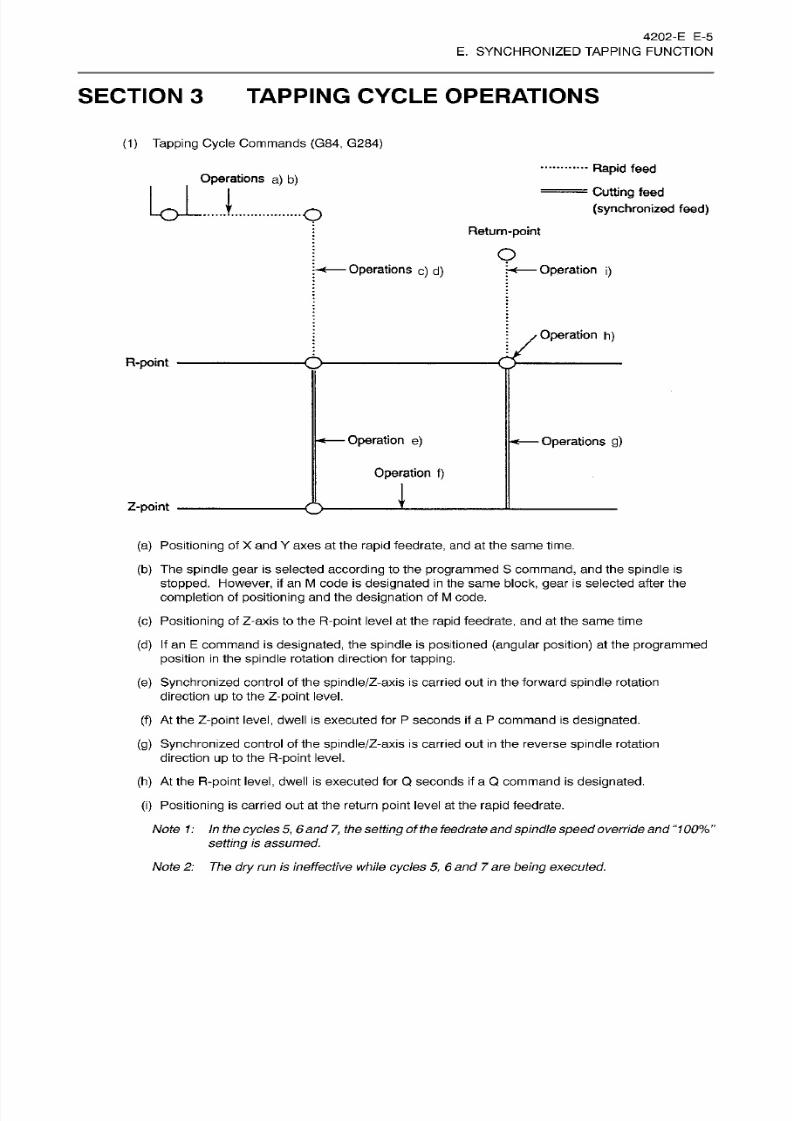
8/15/2019 Okuma Manuals 391
http://slidepdf.com/reader/full/okuma-manuals-391 168/397
4202-E E-5
E. SYNCHRONIZED TAPPING FUNCTION
SECTION 3
TAPPING
CYCLE
OPERATIONS
(1)
Tapping
Cycle Commands
{G84, G284)
Rapid
feed
Cutting
feed
(synchronized feed)
Operations
a)
b)
U-
t
O
Return-point
o
Operations
c)
d)
Operation
i)
Operation
h)
R-point
Operation
e)
Operations
g)
Operation
f)
1
-point
(a) Positioning
of
X
and
Y
axes at
the rapid
feedrate,
and
at
the
same time.
(b)
The spindle
gear is selected according to
the
programmed
S
command,
an d
the spindle is
stopped.
However,
if an M code
is
designated in the same block,
gear
is
selected after
the
completion
of
positioning
and
the
designation
of
M
code.
(c)
Positioning
of
Z-axis
to the
R-point
level at the
rapid
feedrate,
and
at the
same
time
(d) If
an
E
command
is
designated,
the spindle is
positioned (angular position) at
the
programmed
position
in
the
spindle
rotation direction
for
tapping.
(e)
Synchronized
control of the spindle/Z-axis
is
carried out in
the
forward spindle rotation
direction
up
to
the
Z-point
level.
(f)
At the Z-point
level,
dwell
is
executed for
P
seconds
if
a
P
command is
designated.
(g) Synchronized
control of the
spindle/Z-axis
is carried out
in
the
reverse
spindle rotation
direction
up
to the
R-point
level.
(h)
At
the R-point
level,
dwell is executed
for
Q
seconds
if
a Q command
is
designated.
(i) Positioning
is carried
out
at
the
return
point
level at the
rapid
feedrate.
Note
1: In the cycles
5,
6
and
7,
the
setting
of
the
feedrate and
spindle speedoverride
and
“100%
”
setting
is assumed.
Note
2:
The
dry
run
is
ineffective
while
cycles
5,
6
and
7
are
being
executed.
8/15/2019 Okuma Manuals 391
http://slidepdf.com/reader/full/okuma-manuals-391 169/397
4202-E E-6
E. SYNCHRONIZED TAPPING FUNCTION
(2 )
Reverse
Tapping
Cycle Commands
(G74,
G274)
Compared
to the
cycles
explained
in (1),
the
spindle
rotating
direction for the
cycles
4,
5
and
7 is
reversed.
Other
operations
are
completely
the same as explained
in
(1).
1. In the tapping cycle using
the
floating
tapper,
the sPindle is rotating
at the
completion
of
the
cycle.
However,
in
the
synchronized tapping
cycle,
the
spindle
stops
at the
completion
of the
cycle.
2. If the
control
is
reset
during synchronized
tapping
cycle,
the
gear
remains
as
selected
for the
synchronized tapping
operation.
However,
the
gear is selected
according
to the S
command
value when the
spindle
rotation command
(M03,
M04),
spindle
orientation command
(M19, M118, M119),
S
command,
or
manual
spindle operation
is executed after that.
[Supplement]
(3)
Slide Hold
(a)
When
the
SLIDE
HOLD
button
is
pressed
during
the
execution of step 5, the spindle stops
immediately.
The Z-axis
is
fed
to
the
R-point level while being controlled
in
synchronization
with
spindle
reverse rotation. When the
Z-axis
has
reached
the R-point
level,
it stops.
(b)
When the
SLIDE
HOLD button is pressed
during
the
execution
of
step
5, the Z-axis is
decelerated.
However,
the distance up to the R-point
level is
larger
than the
distance up to the
Z-point level,
the
tapping cycle is
continued while
ignoring
the slide hold command. The Zaxis
stops
when it has
reached
the
R-point
level.
(c)
When the
SLIDE
HOLD button is
pressed
during
the execution of
step
6
or
7,
the Z-axis
stops
after it
has reached the
R-point
level.
(d)
When the CYCLE
START
button
is
pressed
while
the
Z-axis is
temporari ly stopped
at
the
R-point
level, synchronized
control of the
spindle/Z-axis
is
carried out
up
to the
Z-point
level.
[Supplement]
The
MID
AUTO MANUAL
key
is not
operative
when
the
Z-axis is
temporarily
stopped
at
the
R-point
level.
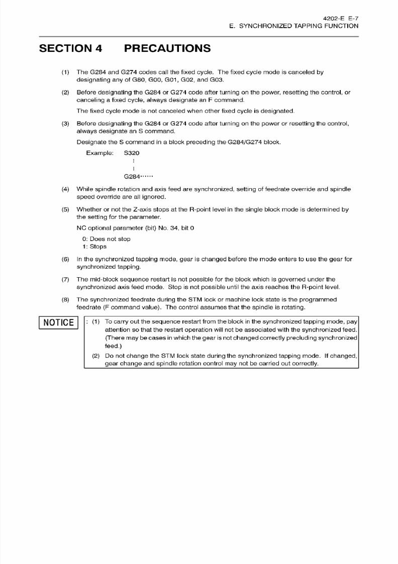
8/15/2019 Okuma Manuals 391
http://slidepdf.com/reader/full/okuma-manuals-391 170/397
4202-E
E-7
E. SYNCHRONIZED TAPPING FUNCTION
SECTION 4
PRECAUTIONS
The G284
and
G274
codes
call
the
fixed
cycle. The
fixed
cycle
mode
is canceled by
designating any
of
G80,
GOO,
G01
, G02,
and
G03.
Before
designating the
G284 or G274
code
after
turning
on
the
power,
resetting
the
control, or
canceling
a
fixed
cycle,
always
designate
an
F
command.
The fixed cycle
mode is not canceled
when
other fixed
cycle
is
designated.
Before
designating
the
G284
or G274 code after
turning
on
the
power
or
resetting
the
control,
always
designate
an S command.
Designate the S command in
a block
preceding
the
G284/G274
block.
Example:
S320
(1)
(2)
(3)
;
G284
(4)
While spindle rotation and
axis
feed
are
synchronized,
setting
of
feedrate
override and spindle
speed override are al l
ignored.
Whether
or not the
Z-axis stops at
the
R-point
level
in
the
single
block
mode is
determined
by
the
setting
for
the parameter.
NC optional parameter
(bit)
No.
34,
bit
0
0:
Does not
stop
1
: Stops
In
the
synchronized tapping mode,
gear
is
changed
before
the
mode enters
to
use
the
gear for
synchronized tapping.
The
mid-block sequence restart
is
not
possible
for the block which is
governed
under
the
synchronized
axis feed mode.
Stop
is not
possible
until the axis reaches the
R-point
level.
The
synchronized
feedrate
during
the
ST M lock
or
machine lock
state is the
programmed
feedrate
(F
command
value).
The control
assumes
that the
spindle
is
rotating.
(5)
(6)
(7)
(8)
NOTICE
:
(1) To
carry
out the
sequence restart
from
the block in
the
synchronized
tapping mode,
pay
attention so that the restart
operation
will
not be associated
with
the
synchronized
feed.
(There may
be cases
in which
the
gear is not changed correctly precluding
synchronized
feed.)
(2)
Do
not
change the STM
lock state
during the synchronized tapping mode. If changed,
gear change an d
spindle
rotation
control may not be carr ied
out
correctly.
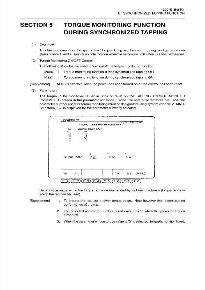
8/15/2019 Okuma Manuals 391
http://slidepdf.com/reader/full/okuma-manuals-391 171/397
4202-E E-8-R1
E. SYNCHRONIZED
TAPPING
FUNCTION
SECTION 5
TORQUE
MONITORING FUNCTION
DURING SYNCHRONIZED TAPPING
(1)
Overview
This
functions monitors the
spindle
load
torque
during synchronized tapping,
an d generates
an
alarm
of
level B and suspends
spindle
rotation when
the set
torque
limi t value has been
exceeded.
(2) Torque
Monitoring
ON/OFF
Control
The
following
M
codes are
used
to turn
on/off
the
torque
monitoring
function.
M326 Torque
monitoring
function
during synchronized
tapping OFF
M327
Torque
monitoring
function
during synchronized tapping
ON
[Supplement]
M326 is
effective
when the
power
has
been
turned on or the control has been reset.
(3)
Parameters
The
torque
to
be monitored
is
set
in
units
of
N*m
on
the
TAPPING
TORQUE
MONITOR
PARAMETER
screen
in
the parameter
set
mode.
Since
five
sets
of
parameters
are
used,
the
parameter
number used for
torque
monitoring
must be
designated using
system
variable VTMNO.
An
asterisk
is displayed
for
the
parameter
currently
selected.
I
PARAMETER
SE T
97/07/15
14:i0:00
*
TAPING
TORQUE
MONITOR
PARAMETER
*
MONITOR
TORQUE [N*m]
O.
'00
*
1
2
15
3
0
5-
127
X
v
z
ACT
POSIT
(WORK)
0.001
A-Mtd
0.001 0.001
ITEM
T
ITEM
i
[EXTEND]
ET ADO
[~F~I
if
F
2
H
F~
3
)
[
F zi
lrrinrFnrmrm
Set a
torque
value within the
torque range recommended
by
tool manufacturers
(torque range in
which
the tap
ca n be used).
[Supplement]
1
.
To
protect the
tap,
set
a
lower
torque value.
Note however
this lowers
cutting
performance
of the
tap.
2.
The selected parameter
number
is
not
erased
even when
the
power
has been
turned off.
3. When
the
parameter
whose
torque
value
is
“0 ”
is
selected,
torque
is
not monitored.
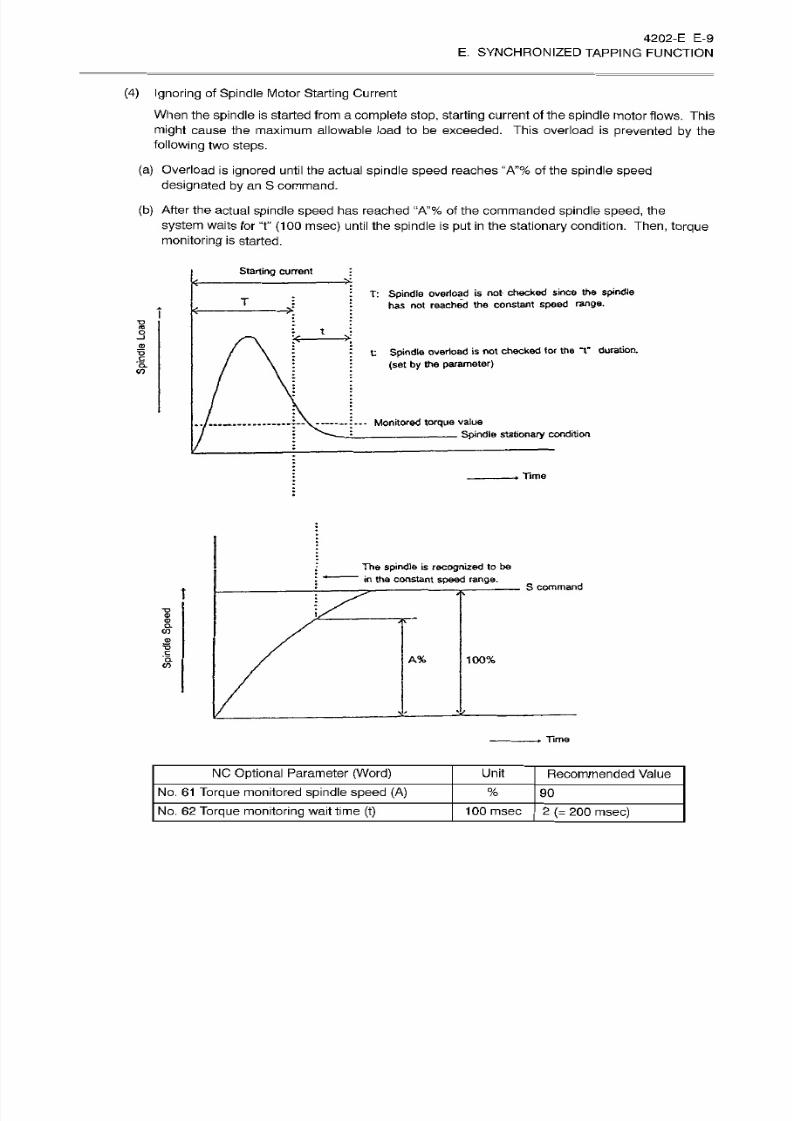
8/15/2019 Okuma Manuals 391
http://slidepdf.com/reader/full/okuma-manuals-391 172/397
4202-E
E-9
E.
SYNCHRONIZED TAPPING
FUNCTION
(4 )
Ignoring
of
Spindle
Motor
Starting
Current
When the
spindle
is
started from
a
complete
stop,
starting current of the
spindle
motor
flows.
This
might cause
the maximum
allowable
load to be exceeded.
This
overload is
prevented
by the
following
two
steps.
(a)
Overload
is ignored
until
the
actual
spindle speed reaches “A”%
of
the
spindle
speed
designated by
an
S command.
(b)
After
the
actual
spindle speed
has
reached “A”%
of the
commanded spindle
speed,
the
system
waits
for
T
(100
msec)
until
the spindle
is put in
the
stationary condition.
Then, torque
monitoring
is
started.
Starting current
T:
Spindle
overload
is
not
checked
since
the
spindle
has
not reached
the constant
speed
range.
13
t
3
<-
o
t
spindle
overload
is not
checked
to r
the
*Y
duration.
(set by
the
parameter)
M
.
—
:
—
Monitored
torque
value
Spindle
stationary
condition
Time
The
spindle
is
recognized
to be
in the
constant
speed
range.
S
command
1
O.
c
n
©
A%
100%
CO
Time
NC Optional
Parameter
(Word)
Unit
Recommended
Value
No.
61 Torque
monitored
spindle speed
(A)
%
90
No.
62
Torque
monitoring wait time
(t) 1
00
msec
2
(=
200
msec)

8/15/2019 Okuma Manuals 391
http://slidepdf.com/reader/full/okuma-manuals-391 173/397
4202-E
E-10
E. SYNCHRONIZED TAPPING FUNCTION
(5) Torque
Monitoring
Method
If the spindle load
torque
exceeds the set value for about
10;Tn
(msec)
continuously,
the
following
alarm is
displayed
and the
spindle stops immediately.
The
Z-axis
is
fed
to the
point-R
level
in
the
synchronization
with
spindle
reverse
rotation. When the Z-axis has reached the
R-point
level,
it
stops.
Alarm
B 2447 Synchronous
tap’s torque
low
The
torque
is monitored until deceleration
is started.
A value for “n” is set
at
NC
optional parameter (word)
No.
21
.
NC optional
parameter
(word)
No. 21
Allowable number
(n)
for
torque
over
monitoring
-
recommended value: 4
[Supplement]
Torque
monitoring
is not carried out when “0” is set.
(6)
Display
The
torque
monitoring
process
is
displayed
on
the
following three screens: 2nd page
of
the
ACTUAL POSITION
screen,
the
MAIN
PROGRAM
(execution)
screen,
and the
MAIN
PROGRAM
(read)
screen. A sym bol “V” is indicated
above
the
LOAD DISPLAY
bar graph. This
is
the
maximum
load
torque.
AUTO OPERATION
TEST-1
.lilIN
0100 MA3
J5_
97/07/15
14:10:00
LOAD
DISPLAY
CTUAL POSITION
1m m
200
{%)
100
0.000
0.000
0.000
0.0000
X
T
s
Y
T65?T
TORQUE
MON
I
TOR
(110%)
Z
X
OK
B
Y
OKo
0
0
100
z
.0M
OK
H=
0 TOUCH
SENSOR
D=
0
TOUCH
PROBE
B
OK
CHECK
ROGRAH
ACTUAL
PART
BLOCK
SELECT
I
POSIT
I
PROGRAM
I
DATA
[EXTEND]
SEARCH
DATA
rFÿrr2iroiirTÿrFÿnnnfiÿiT~ÿ
2nd
Page of the
ACTUAL POSITION Screen
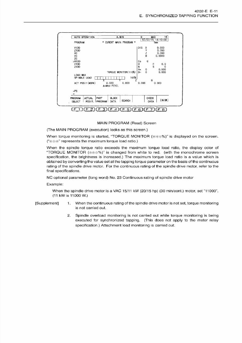
8/15/2019 Okuma Manuals 391
http://slidepdf.com/reader/full/okuma-manuals-391 174/397
4202-E
E-11
E. SYNCHRONIZED TAPPING FUNCTION
I
AUTO OPERATION
A. MIN
0
MA3 J5_
97/07/15
14:10:00
*
CURE
NT MAIN
PROGRAM
*
ROGRAM
lm m
Y100
DIS
X 0.000
0.000
0.000
0.0000
Z10C
Y
xc
z
B
O
zc
>X100
Co
0
Y100 0
F
0.0
Z100
N
s
0
0 0.000
0.000
H=
TOROUE MON
I
TOR
(11
OX )
D= 0
LOAD
MAX
SPINDLE
LOAD
1
6554
T
V
z B
ACT POSIT
(WORK)
0.000 0.000
A-Mtd FCYCL
0.000 0.000
=PS
PROGRAM
ACTUAL
PART BLOCK
SELECT
I
POSIT.
I
PROGRAM
I
DATA
CHECK
mm
EARCH
DATA
MAIN
PROGRAM
(Read)
Screen
(The MAIN
PROGRAM
(execution)
looks as this
screen.)
When
torque
monitoring
is
started,
“TORQUE
MONITOR
(;['**%)”
is
displayed
on the screen.
(“> <*>]<” represents
the maximum
torque
load
ratio.)
When
the
spindle torque
rat io exceeds
the
maximum
torque
load ratio, the display
co lo r of
“TORQUE
MONITOR
(>M<*%)
is
changed
from
white to red.
(with
the monochrome screen
specification,
the brightness is
increased.)
The
maximum
torque
load
ra tio is
a
value which
is
obtained
by converting the
value set at
the tapping
torque parameter
on the basis of
the continuous
rating of the spindle drive motor.
For
the continuous rating of the spindle drive
motor,
refer
to the
final
specifications.
NC
optional parameter
(long
word)
No.
23
Continuous rating
of spindle drive
motor
Example:
When the spindle drive motor is a VAC
15/11
kW
(20/15 hp) (30 min/cont.)
motor, set
“11000”.
(11 kW
is 11000 W.)
[Supplement] 1
.
When the continuous
rating
of the spindle drive
motor
is no t set,
torque
monitoring
is
not
carried
out.
2.
Spindle
overload
monitoring
is
not carried
out while
torque
monitoring
is
being
executed
for
synchronized
tapping.
(This
does
not
apply
to the meter
relay
specification.)
Attachment
load
monitoring is carried out.

8/15/2019 Okuma Manuals 391
http://slidepdf.com/reader/full/okuma-manuals-391 175/397
4202-E
E-12
E. SYNCHRONIZED TAPPING FUNCTION
(7)
System
Variables
(a)
Tapping
torque monitored
parameter
No.
[VTMNO]
-
Read and write
operations
are
possible.
-
Setting range
-
The
value
set at
“VTMNO”
is backed
up .
When a value is not
set,
the
value
previously
set
becomes
effective.
Initial
setting
is
“1 .
(b)
Tapping
torque
monitored
parameter
1
to
5
[VTMDT
(n)]
-
“n”
means
parameter
No. 1 to
5
-
Only
read
operation
is
possible.
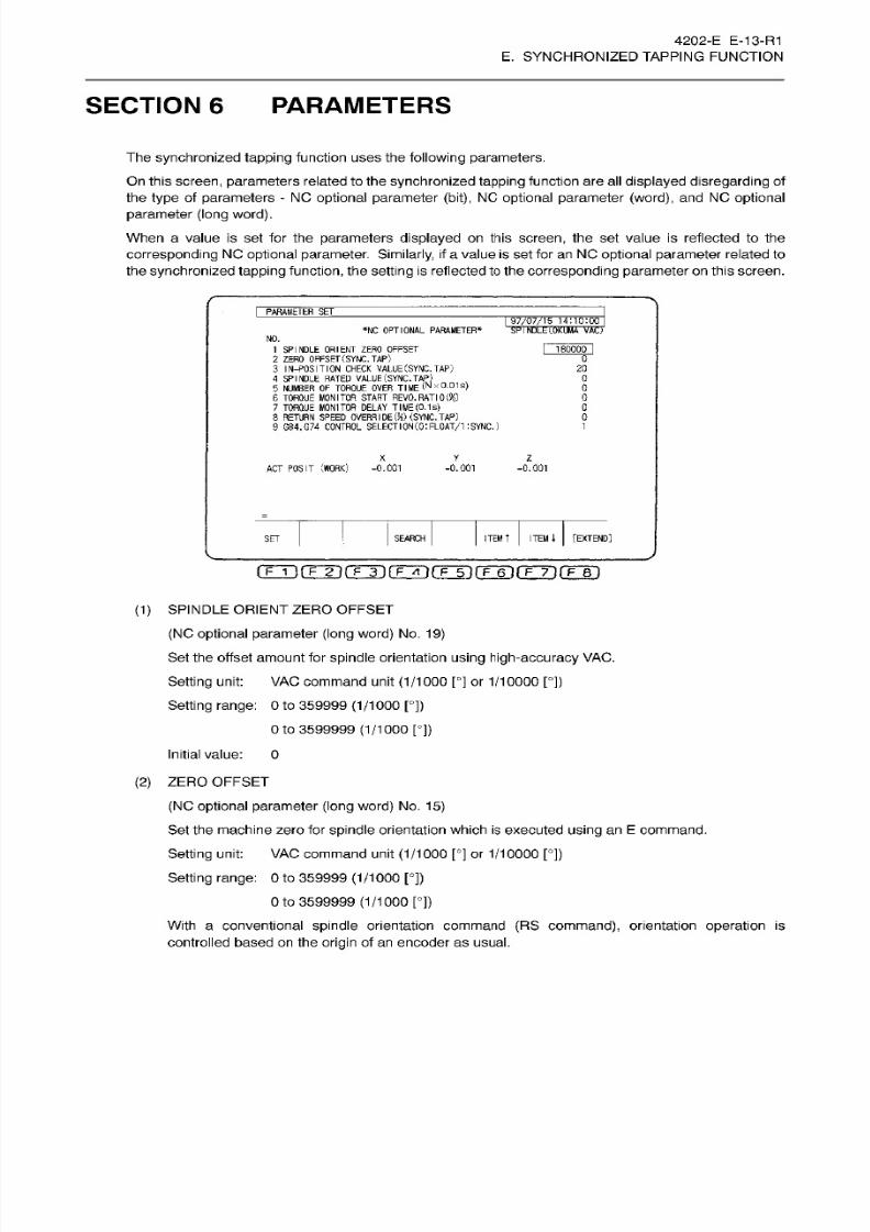
8/15/2019 Okuma Manuals 391
http://slidepdf.com/reader/full/okuma-manuals-391 176/397
4202-E E-13-R1
E. SYNCHRONIZED
TAPPING
FUNCTION
SECTION 6 PARAMETERS
The synchronized tapping
function
uses the fol lowing
parameters.
On this
screen,
parameters
related to the
synchronized tapping
function are all
displayed disregarding
of
the
type
of
parameters
-
NC
optional parameter
(bit),
NC
optional
parameter
(word),
and NC optional
parameter
(long word).
When
a
value is
se t
for the
parameters displayed
on this
screen,
the
set value is
reflected
to the
corresponding
NC
optional
parameter.
Similarly,
if
a
value
is se t for an NC
optional
parameter
related to
the
synchronized tapping function,
the
setting
is
reflected
to the
corresponding
parameter
on this screen.
I
PARAMETERW
|
97/07/15
14:10:00
*NC OPTIONAL
PARAMETER*
SP
I
NDLE
I.OKUMA VACJ
NO.
180000
I
SPINDLE
ORIENT ZERO
OFFSET
2
ZERO OFFSET
(SYNC.
TAP)
3
IN-POSITION CHECK
VALUE
(SYNC.
TAP)
4 SPINDLE RATED VALUE
(SYNC.
TAP)
5 NUMBER
OF
TORQUE
OVER
T
I
ME
(N
x°-01
s>
6
TORQUE
M O NITO R S T AR T
REVO.
RATION)
1 TORQUE
MONITOR
DELAY
TIME
(0.1s)
8 RETURN SPEED
OVERRIDE®
(SYNC.
TAP)
9
G84.G74
CONTROL
SELECTION(0:
FLOAT/I
:
SYNC.
)
¥
20
0
0
0
0
0
1
X
Y
z
AC T
POSIT
(WORK)
-0.001
-0,
001 -0.001
ITEMt ITEMi
[EXTEND]
EARCH
ET
nÿfFin(Tÿ iTÿrÿ inrF~6~)rF~7i fF i r )
(1 )
SPINDLE ORIENT ZERO OFFSET
(N C
optional
parameter
(long
word)
No.
19 )
Set
the offset amount for
spindle
orientation using
high-accuracy
VAC.
Setting
unit: VAC
command
unit
(1/1000
[°]
or
1/10000
[°])
Setting range:
O to 359999
(1/1000
[°])
O to 3599999
(1/1000
[°])
Initial
value:
0
(2)
ZERO
OFFSET
(N C
optional
parameter
( long word) No.
15)
Set the
machine
zero
for spindle orientation
which
is executed
using an
E
command.
Setting
unit:
VA C command
unit
(1/1000
[°] or
1/10000
[°])
Setting
range: 0
to 359999
(1/1000 [°])
Oto
3599999
(1/1000 [°])
With
a
conventional
spindle
orientation command
(R S command),
orientation
operation is
controlled
based
on
the
origin
of
an
encoder
as
usual.
8/15/2019 Okuma Manuals 391
http://slidepdf.com/reader/full/okuma-manuals-391 177/397
4202-E E-14-R1
E. SYNCHRONIZED
TAPPING
FUNCTION
(3)
IN-POSITION CHECK VALUE
(N C optional
parameter
( long word)
No.
16)
Set the
spindle
in-position
check value to be
applied
to
synchronized tapping operation.
Setting
unit: VAC command unit
(1/1000
[°]
or
1/10000
[°])
Setting range:
1
to 359999
(1/1000
[°])
10 to 3599999
(1/1000
[°])
(4)
SPINDLE
RATED
VALUE
(NC
optional parameter
(long word) No.
23)
Setting
unit:
W (watt)
Setting range:
11
0
to
99999999
Initial value:
0
(5)
NUMBER
OF
TORQUE
OVER
TIME
(NC optional
parameter
(word)
No.
21)
Setting
unit: Times
Setting range:
0 to 32
Initial value: 0
Recommended
setting: 4
[times]
(6) TORQUE MONITOR START REVO. RATIO
(NC optional
parameter
(word)
No.
61)
Setting
unit:
%
Sett ing range:
Oto 100
Initial value: 0
Recommended setting: 90 [%]
(7)
TORQUE MONITOR
DELAY TIME
(NC
optional
parameter
(word) No. 62)
Setting
unit:
100 msec
Setting range:
Oto 1000
Initial
value: 0
Recommended
setting: 2 (200 [msec])
(8)
RETURN SPEED
OVERRIDE
(NC
optional parameter
(word)
No.
113)
Setting
unit:
%
Setting
range:
1
to 200
Initial value:
0
(treated
as
100
[%])

8/15/2019 Okuma Manuals 391
http://slidepdf.com/reader/full/okuma-manuals-391 178/397
4202-E E-15
E. SYNCHRONIZED TAPPING FUNCTION
(9)
G84,
G74 CONTROL SELECTION
(NC optional
parameter
(bit)
No. 17,
bit
7)
Specify
whether G84 and
G74,
specified
in
a
program,
should be controlled
in
the float
tapping
mode or
the synchronized tapping
mode.
[0]
:
G84
and
G74
are
controlled in
the float
tapping
mode.
[1]: G84
an d
G74
are
controlled in
the
synchronized
tapping mode.

8/15/2019 Okuma Manuals 391
http://slidepdf.com/reader/full/okuma-manuals-391 179/397
F. TOOL MANAGEMENT FUNCTION
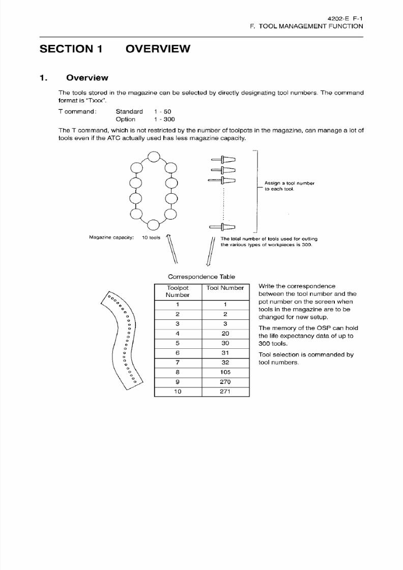
8/15/2019 Okuma Manuals 391
http://slidepdf.com/reader/full/okuma-manuals-391 180/397
4202-E
F-1
F.
TOOL MANAGEMENT FUNCTION
SECTION
1
OVERVIEW
1.
Overview
The
tools stored in the
magazine
can
be selected
by directly designating
tool numbers. The
command
format is “Txxx”.
T command
:
Standard
Option
The
T
command,
which
is
not
restricted by
the number of
toolpots in
the
magazine,
can manage
a lot of
tools
even if the
ATC
actually
used
has
less
magazine capacity.
1
-50
1
-300
Assign
a
tool number
—
to each tool.
Magazine
capacity:
10 too ls
Th e
total
number
of
tools used fo r cutting
the various
types
of workpieces is 300.
Correspondence
Table
Write
the
correspondence
between the tool number and the
pot
number on the screen when
tools
in
the
magazine
are to
be
changed
for
new
setup.
The
memory
of the
OSP can hold
the life
expectancy
data
of
up
to
300
tools.
Tool
selection
is
commanded by
tool
numbers.
Too
Ipot
Number
Tool
Number
°°oo
1
1
2
2
o
3 3
4
20
o
5 30
o
6
31
o
7
32
o
8 10 5
o
9
27 0
10
271
8/15/2019 Okuma Manuals 391
http://slidepdf.com/reader/full/okuma-manuals-391 181/397
4202-E
F-2
F.
TOOL MANAGEMENT FUNCTION
SECTION 2 DESCRIPTION
OF
MANAGEMENT FOR
EACH TOOL
NUMBER
1.
Tool
Offset
Number
The tool
offset
numbers are
normally
specified
in
a part
program
as
H
number or
D
number
directiy.
In
addition,
1st
offset number, 2nd offset number and 3rd offset number can be used for specification.
When the
tool offset
data is
considered
to be
particular
to
each
tool,
the
tool offset
number
is
determined
solely corresponding
to the tool to be used.
This
concept is
essential for
spare tool
changing.
Because
the
tool offset number
of a spare tool cannot
be
specified
in
a
part
program.
(1)
1st
Offset Number
Specify HA
or
DA
in the
part
program.
-
HA
substitutes for the conventional
tool
length
offset number.
-
DA
substitutes for the conventional cutter
radius
compensation
number.
When
specifying HA
or
D A, H
number or
D
number
will be
the same number
as
the tool number of
the
active tool.
(2)
2nd Offset Number
Specify HB
or
DB
in the
part
program.
-
HB
substitutes for the conventional tool
length
offset
number.
-
DB
substitutes
for
the conventional
cutter
radius
compensation
number.
When specifying
HB
or
DB, the
number
of offset
number
2
which has
setforthe
tool number
of
the
active tool
will
be
H
or
D number, respectively.
(3)
3rd
Offset
Number
Specify
HC or
DC
in
the
part
program.
-
HC substitutes
for the
conventional tool
length
offset number.
-
DC substitutes
for the
conventional cutter
radius
compensation
number.
When specifying
HC or
DC, the
number of offset number
3
which has set
for
the
tool
number of
the
active
tool
will
be
H
or
D
number,
respectively.
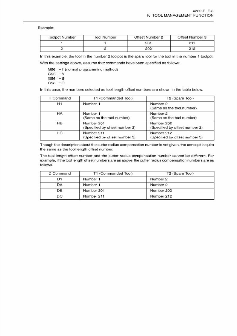
8/15/2019 Okuma Manuals 391
http://slidepdf.com/reader/full/okuma-manuals-391 182/397
4202-E
F-3
F.
TOOL MANAGEMENT FUNCTION
Example:
Offset Number
2
Offset Number 3oolpot Number
Tool
Number
1 1
201
211
2
2 202
212
In
this example,
the
tool in
the number
2
toolpot
is the spare tool for the
tool in the
number
1
toolpot.
With
the
sett ings above,
assume
that
commands
have
been
specified
as
follows:
G56
H1
(normal programming method)
G56
HA
G56
HB
G56
HC
In this case, the
numbers selected as tool
length
offset
numbers are
shown in
the table below.
H
Command
T1 (Commanded Tool) T2 (Spare Tool)
Number
1
Number
2
(Same
as the tool
number)
H1
HA Number
1
(Same
as the tool
number)
Number
2
(Same
as the tool
number)
HB
Number
20 1
(Specified
by
offset number 2)
Number
20 2
(Specified
by
offset number 2)
HC
Number
211
(Specified by
offset number
3)
Number 212
(Specified by
offset number
3)
Though the
description
about
the cutter radius
compensation
number is not given,
the
concept
is
quite
the same as the tool
length
offset number.
The tool
length
offset number
and
the
cutter
radius
compensation number
cannot
be
different. For
example, if
the tool
length
offset
numbers
are as
above, the
cutter radius compensation
numbers are
as
follows.
D Command T1
(Commanded
Tool)
T2
(Spare
Tool)
D1
Number
1
Number
2
DA
Number
1 Number
2
DB Number
20 1
Number
20 2
DC Number
211
Number 212
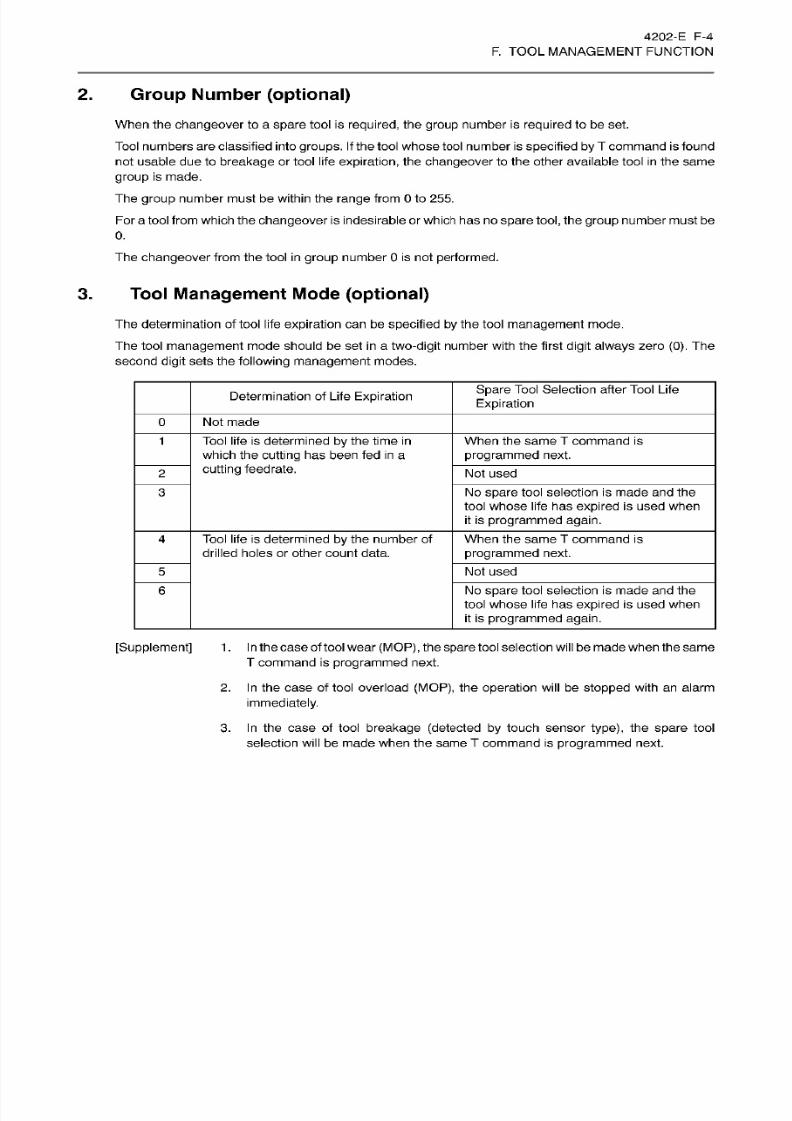
8/15/2019 Okuma Manuals 391
http://slidepdf.com/reader/full/okuma-manuals-391 183/397
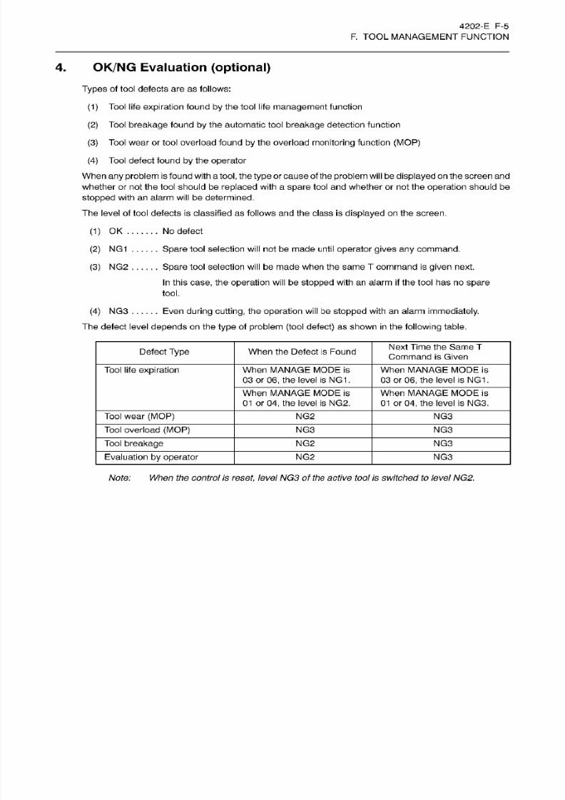
8/15/2019 Okuma Manuals 391
http://slidepdf.com/reader/full/okuma-manuals-391 184/397
4202-E F-5
F.
TOOL MANAGEMENT FUNCTION
4.
OK/NG
Evaluation
(optional)
Types
of
tool
defects are
as
follows:
(1)
Tool life
expiration
found by the tool
life
management
function
(2)
Tool
breakage
found
by
the
automatic tool
breakage
detection function
(3)
Tool
wear or tool overload found
by
the overload
monitoring function
(MOP)
(4)
Tool
defect
found
by
the
operator
When any
problem
is
fou
nd with a tool,
the
type
or cause of
the
problem will
be
displayed on the screen
and
whether or no t the
tool
should be
replaced
with
a
spare
too l and whether or
not
the
operation
should
be
stopped with
an alarm
will
be determined.
The level
of
tool defects is classified as follows and the class is
displayed
on the screen.
(1) OK.
(2)
NG1
(3)
NG 2
No
defect
Spare
tool
selection
will
not
be made until
operator
gives any
command.
Spare
tool selection
will
be made when the
same
T command is
given
next.
In
this case, the
operation
will
be
stopped
with
an alarm
if
the tool has no
spare
tool.
(4)
NG3
......ven
during cutting,
the
operation will
be
stopped
with an alarm immediately.
The defect level
depends
on the
type
of
problem
(tool
defect)
as shown in the following table.
Next Time
the Same T
Command
is Given
efect
Type
When the Defect is Found
Tool
life
expiration
When
MANAGE
MODE
is
03
or
06,
the level
is
NG 1.
When
MANAGE
MODE
is
03 or 06 ,
the
level is
NG1
.
When
MANAGE
MODE
is
01 or
04,
the leve l is NG2.
When
MANAGE
MODE
is
01 or
04,
the leve l is
NG3.
Tool
wear (MOP) NG2
NG 3
Tool overload
(MOP)
NG3 NG3
Tool
breakage
NG2 NG3
Evaluation
by
operator NG2 NG3
Note: When the
control
is
reset,
levelNG3
of
the
active
tool is
switched
to
level
NG2.
8/15/2019 Okuma Manuals 391
http://slidepdf.com/reader/full/okuma-manuals-391 185/397
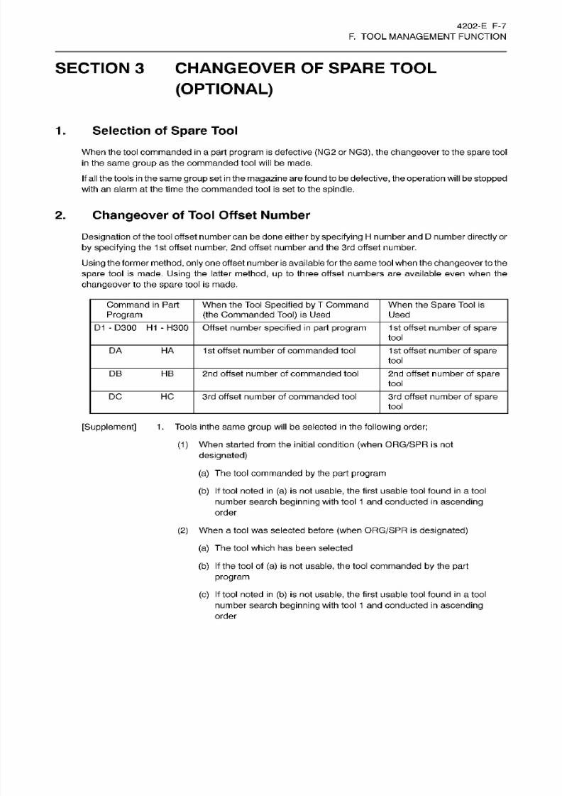
8/15/2019 Okuma Manuals 391
http://slidepdf.com/reader/full/okuma-manuals-391 186/397
4202-E
F-7
F.
TOOL MANAGEMENT FUNCTION
SECTION 3 CHANGEOVER
OF
SPARE TOOL
(OPTIONAL)
1
.
Selection
of
Spare
Tool
When the tool commanded
in
a
part
program
is
defective (NG2 or NG3), the
changeover
to the
spare
tool
in the
same
group
as the
commanded
tool
will be
made.
If
al l
the
tools in
the
same
group set
in
the magazine are
found to
be defective, the
operation
will
be
stopped
with an alarm at
the time the
commanded
tool is
set to the
spindle.
2.
Changeover
of
Tool
Offset Number
Designation
of the tool offset number
can
be done either
by specifying H number and D
number
directly
or
by
specifying
the
1st offset
number,
2nd
offset
number
and
the
3rd
offset
number.
Using the
former
method,
only
one
offset
number
is available for
the same tool when
the
changeover
to
the
spare
tool
is
made.
Using
the
latter
method, up
to three
offset
numbers
are
available even when the
changeover
to the
spare
tool is made.
Command
in
Part
Program
When
the
Tool
Specified
by
T
Command
(the
Commanded
Tool) is
Used
When
the
Spare
Tool is
Used
D1
-
D300
H1
-
H300
Offset number
specified
in
part
program 1st
offset
number
of
spare
tool
DA
HA
1st offset number of
commanded
tool 1st offset number of
spare
tool
2n d offset number of
commanded
tool 2nd
offset number
of
spareB
HB
tool
DC
HC
3rd
offset
number of
commanded
tool
3rd
offset
number
of
spare
tool
[Supplement]
1
.
Tools
inthe
same
group
will
be selected
in
the following
order;
(1)
When started from the initial condition
(when
ORG/SPR
is
not
designated)
(a)
The
tool commanded by
the part program
(b)
If
tool
noted
in (a)
is
not
usable,
the
first
usable
tool found
in
a
tool
number
search beginning
with tool
1
an d
conducted in ascending
order
(2)
When
a tool
was selected
before
(when
ORG/SPR
is designated)
(a)
The
tool
which
has
been
selected
(b) If
the tool of
(a)
is
not
usable,
the
tool commanded
by
the
part
program
(c) If
tool
noted
in
(b)
is not
usable,
the
first
usable tool
found
in
a tool
number
search
beginning
with
tool
1 and
conducted
in ascending
order
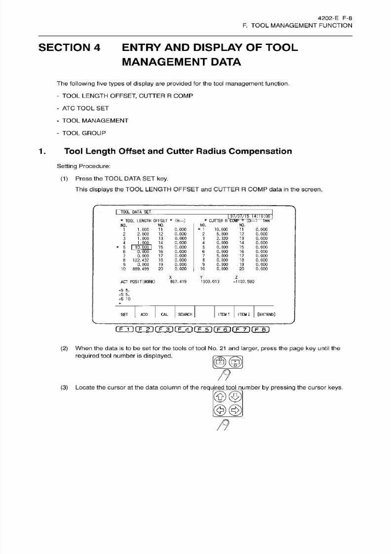
8/15/2019 Okuma Manuals 391
http://slidepdf.com/reader/full/okuma-manuals-391 187/397
4202-E
F-8
F.
TOOL MANAGEMENT FUNCTION
SECTION 4 ENTRY AND DISPLAY OF TOOL
MANAGEMENT
DATA
The
following
five
types
of display are
provided for the tool
management
function.
-
TOOL
LENGTH
OFFSET,
CUTTER
R
COMP
-
AT C
TOOL
SET
- TOOL MANAGEMENT
-
TOOL
GROUP
1.
Tool Length
Offset
and Cutter
Radius
Compensation
Setting
Procedure:
(1 )
Press
the TOOL
DATA
SET key.
This
displays
the TOOL
LENGTH OFFSET an d CUTTER
R
COMP
data in
the
screen.
TOOFOATA SE T
I
s.7,/07/15.1'1-10.-00
*
CUTTER R COMP
*
(D—
)
Tim
*
TOOL LENGTH
OFFSET
*
(H—
)
NO.
NO.
NO.
NO.
0.000
0.000
0.000
0.000
15
0.000
16
0.000
0.000
0.000
0.
000
0.
000
*
1
10.000
2
5.000
3
2.320
4
0.000
5 0.000
6 0.000
5.000
8
0.000
9
0.000
10 0.000
11
0.000
12
0.000
13 0.000
14
0.000
15
0.000
16
0.000
17
0.000
18
0.000
19
0.000
20
0.000
1
1.000 11
2
2.000
12
3 1.000
13
4
1.00Q_
14
*
5
rnn
6 0.
7
0.000
17
8
122.432 18
9 0.000
19
10 889.499
20
7
Z
Y
ACT POSIT
(WORK)
867.419
1000.013
-1102.580
=S 5.
=S
S.
=S
10
[EXTEND]
TE M
t
ITEM
A
AL
SEARCH
ET
ADD
gji(TT)rrTirFÿ(TTi(Tÿ(TÿrF~8')
(2)
When the data
is
to be set for the tools
of
tool No. 21 an d
larger, press
the
page key
until
the
required
tool number
is displayed.
MM
(3)
Locate
the
cursor
at the
data
column
of
the
required
tool number by pressing
the
cursor
keys.
®©
@@
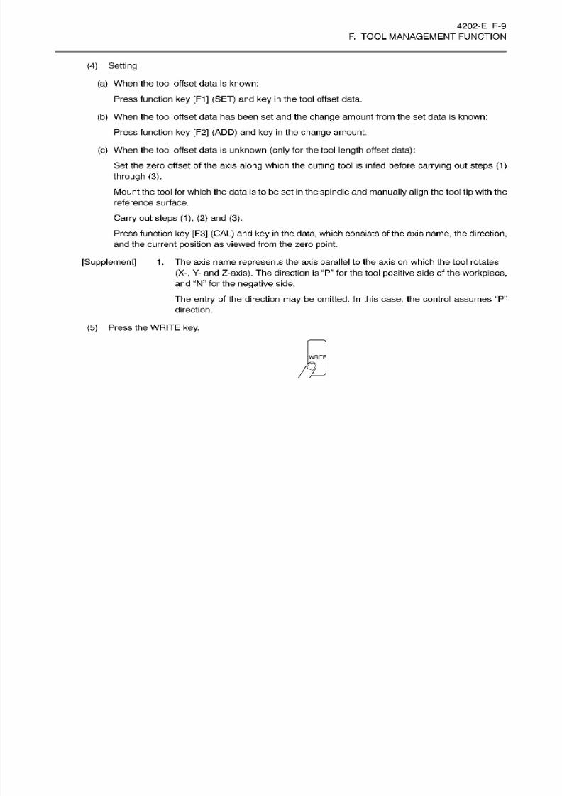
8/15/2019 Okuma Manuals 391
http://slidepdf.com/reader/full/okuma-manuals-391 188/397
4202-E F-9
F.
TOOL MANAGEMENT FUNCTION
(4) Setting
(a) When the tool offset data is known:
Press function
ke y
[F1]
(SET)
and
key in the
tool offset data.
(b) When
the
tool offset data has been set and
the
change
amount
from the set
data
is known:
Press
function
ke y
[F2]
(ADD)
and
ke y in
the
change
amount.
(c) When the tool offset data is unknown
(only
for the
tool
length
offset
data):
Set the zero
offset
of
the
axis
along
which
the
cutting
tool is
infed
before
carrying
ou t
steps
(1)
through
(3).
Mount
the
tool
for which the
data
is to
be
set
in
the
spindle
and
manually align the tool
tip
with the
reference surface.
Carry
out
steps
(1),
(2) and (3).
Press
function
key
[F3]
(CAL) and ke y in the data,
which
consists
of
the axis
name,
the direction,
and
the
current
position as viewed
from
the
zero point.
[Supplement]
1. The axis name
represents
the axis
parallel
to the
axis
on which the tool rotates
(X-,
Y-
and Z-axis). The direction
is
“P ”
for the tool positive side of the workpiece,
and “N”
for
the negative
side.
The
entry
of the direction
may
be
omitted.
In
this
case,
the control
assumes “P”
direction.
(5) Press the
WRITE key.
WRITE
m
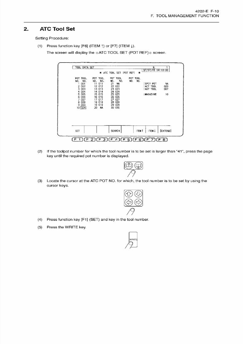
8/15/2019 Okuma Manuals 391
http://slidepdf.com/reader/full/okuma-manuals-391 189/397
4202-E
F-1
0
F.
TOOL MANAGEMENT FUNCTION
2.
ATC Tool
Set
Setting
Procedure:
(1)
Press
function ke y [F6] (ITEM
T)
or
[F7]
(ITEM ().
The
screen
will display
the
*ATC
TOOL
SET
(POT
REF)*
screen.
I
TOOL
DATA
SE T
N_
1
97/07/15
14:10:00
*
ATC TOOL
SE T
(POT REF)
*
PO T TOOL
NO. NO.
1
001
2
002
3 003
4
004
5
005
6 006
7
007
8 008
POT
TOOL
NO. NO.
ii on
12
012
13
013
14
014
15
015
16 016
17
017
18 018
19
019
20 NA
PO T TOOL POT TOOL
NO.
NO. NO. NO.
21 NA
22 022
23 023
24
024
25
025
26
026
27
027
28 02 8
29 029
30 030
ISPCY
POT
:ACT
TOOL
:NXT
TOOL
NA
020
007
:
MAGAZINE
10
9 009
10l02ll
ITEM
i
[EXTEND]
EARCH
ITEM
tET
rrT)fTÿrÿrFFr)rÿirÿ6iiTÿirF~r)
(2)
If
the toolpot
number for
which
the
tool number
is
to be set
is
larger than
“41”,
press
the
page
key
until the
required
pot
number is
displayed.
<
(3) Locate the cursor
at
the ATC
PO T NO.
for which,
the tool
number is to
be
set by using the
cursor keys.
©©
@@
(4)
Press function
key
[F1]
(SET)
and
ke y in
the tool number.
(5)
Press the WRITE
key.
WRITE
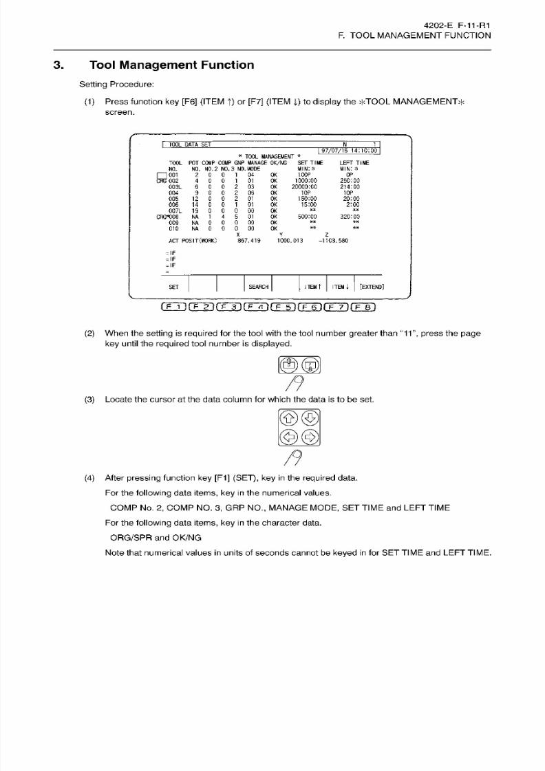
8/15/2019 Okuma Manuals 391
http://slidepdf.com/reader/full/okuma-manuals-391 190/397
4202-E F-11-R1
F.
TOOL MANAGEMENT FUNCTION
3. Tool
Management
Function
Setting Procedure:
(1)
Press
function
key
[F6]
(ITEM t)
or
[F7]
(ITEM 1) to display the
*TOOL
MANAGEMENT*
screen.
I
TOOL
DATA
SET
Jt 1
|
97/07/15
14:10:00
*
TOOL
MANAGEMENT
*
TOOL
PO T C OM P C OM P GNP
MANAGE
OK/NG
NO .
NO.
NO. 2 NO . 3 NO .
MODE
001
2 0
0
1 04 OK 100P
002
4
0
0
1
01
OK
1000:00
003L
6
0 0
2
03 OK 20000:00
004
9
0
0
2
06 OK
005
12
0
0
2
01 OK
006
14
0
0
1
01
OK
007L 19 0 0
0 00
OK
CRG*008
NA 1
4 5 01 OK 500:
00
009
NA
O O
0
00 OK
010 NA
0
O O 00 OK
SE T TIME
MIN:
S
LEFT TIME
MIN:
S
OP
250:00
214:00
10P 10P
’S
20:00
2:00
320:00
X
Y
Z
AC T
POSIT
(WORK)
867.419 1000.013 -1103.580
=
IF
=
IF
=
IF
[EXTEND]
TE M
t
ITEM
l
ET
SEARCH
CFT)
fFin
fF~n
m rim ri
rF~nm ri
(2)
When
the setting
is
required
for the tool with
the
tool
number
greater than “11
”, press
the page
key until the
required
tool number
is
displayed.
00,
(3)
Locate the cursor at the
data
column for which the data is to be
set.
©©
mm
(4)
After
pressing
function key
[F1]
(SET), key
in
the required
data.
Fo r the
following
data items, key
in
the numerical
values.
COMP
No .
2,
COMP NO.
3,
GRP
NO.,
MANAGE
MODE,
SET
TIME
and
LEFT TIME
Fo r the
following
data
items, ke y in
the
character
data.
ORG/SPR
and
OK/NG
Note
that numerical values
in
units
of seconds
cannot
be
keyed in
for
SET
TIME
and
LEFT TIME.
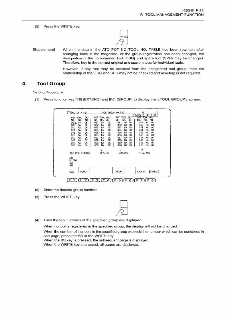
8/15/2019 Okuma Manuals 391
http://slidepdf.com/reader/full/okuma-manuals-391 191/397
4202-E
F-1
2
F.
TOOL MANAGEMENT FUNCTION
(5) Press the
WRITE
key.
WRITE
[Supplement]
When
the
data
in
the
ATC
POT
NO./TOOL
NO.
TABLE
has been
rewritten
after
changing
tools
in
the
magazine,
or the
group
registration
has been
changed,
the
designation
of the commanded tool
(ORG)
and
spare
tool
(SPR)
may be
changed.
Therefore, ke y in
the
correct
original
and
spare
status
for
individual
tools.
However,
If
an y
tool
may
be
selected
from the
designated tool group, then
the
relationship
of
the
ORG and SPR may not be
checked
and
rewriting
is
not required.
4.
Tool
Group
Setting
Procedure:
(1)
Press function key [F8]
(EXTEND)
and
[F5]
(GROUP)
to
display
the
*TOOL
GROUP*
screen.
TOOL GROUP NO. 000TOOL DATA~SET
Ji.
1
97/07/15
14:10:00
POT
TOOL
OK /
NO. NO.
NG
021
NA
OK
022
NA
OK
023
NA OK
024
NA OK
025 NA
OK
026
NA
OK
027
NA
OK
028 NA
OK
029
NA
OK
030
NA
OK
PO T TOOL
OK /
NO. NO. NG
007L 18 OK
009
NA
OK
010 NA
OK
014
NA
OK
015
NA OK
016 NA
OK
017
NA OK
018
NA OK
019
NA
OK
050
NA OK
POT
TOOL
OK/
NO. NO.
NG
031
NA
OK
032
NA
OK
033
NA
OK
034
NA OK
035
NA
OK
036
NA
OK
037 NA
OK
038 NA OK
039
NA
OK
040
NA OK
POT
TOOL
OK/
NO. NO.
NG
041
NA
OK
042
NA
OK
043
NA
OK
044
NA
OK
045
NA
OK
046
NA
OK
047
NA
OK
048 NA OK
049
NA
OK
050
NA
OK
Z
Y
AC T
POSIT
(WORK)
367.419
1000.013 -1102.580
=IB
=S
ORG
=EX
=GR
BACKUP
[EXTEND]
ROUP
EAD PUNCH
rrrÿriÿnHrinÿnÿnHnrFÿrriri
(2) Enter
the
desired
group
number.
(3)
Press the
WRITE
key.
WRITE
(4)
Then
the tool numbers of the
specified
group
are
displayed.
When no tool
is
registered in
the
specified group,
the
display
will
not be
changed.
When the
number
of the tools
in
the
specified
group
exceeds the
number which ca n
be contained
in
one page,
press
the BS or the
WRITE key.
When the BS
key
is
pressed,
the
subsequent
page is
displayed.
When
the
WRITE
key
is
pressed, al l pages are displayed.
8/15/2019 Okuma Manuals 391
http://slidepdf.com/reader/full/okuma-manuals-391 192/397
4202-E F-13
F.
TOOL MANAGEMENT FUNCTION
SECTION 5
RESETTING
DEFECTIVE TOOL
DATA
When a tool is once
found
to be
defective
du e to
various causes
as
described in Section
2,
4.
“OK/NG
Evaluation”,
the
OK/NG
data
of the
tool remains NG until the
operator
rewrites the data to
OK.
When
the
cause
of
the
defect
is removed
or
the
tool
is
changed,
enter
the
data
OK. Other tool
management
data should a lso be
rewritten,
as needed.
Even if
there are
more
than
one
causes
for
the
defect, only one
cause
is
shown
on the
screen.
Thus, when
removing the cause
displayed
and entering the data
“OK”,
the other cause
will be
shown
on the screen
and
the data remains “NG”.
Only
after
all the
causes are
removed,
“OK”
is
shown
on
the screen.
Precautions
in
resetting
NG
data for each
cause are as
follows:
(1) Tool Life (LIFE)
When
the
lower
digit
of
the
TOOL
MANAGEMENT
mode data
is
1 or 4 and the
LEFT T IME
is
negative,
the
tool defect
data
will
be “NG2”. “LIFE” is
displayed
as the cause
on
the
screen.
Change
the
tool
with new
one
and
rewrite the tool life
data,
and
then
rewrite the
OK/NG
data
to
“OK”.
To usethe
current
tool
for a
while,
modify
the tool
management
mode data or
rewrite
the
LEFT
TIME
data
to be
positive, and
then rewrite the
OK/NG
data to “OK”.
(2)
Tool
Breakage (found
by the
automatic tool
breakage
detection function) (BREAK)
When
the toolbreakage is found
by
the
automatic
tool
breakage
detection function,
the
OK/NG
data
will be set
as
“NG2”.
“BREAK”
is
displayed
as
the cause.
Change
the
defective tool with new
one
and then
rewrite
the
OK/NG
data
to
“OK”.
(3)
Overload
(found
by
MOP) (OVLOAD)
When the MOP
sends the
overload alarm
signal,
the
OK/NG
data
will
be
“NG3” andthe NC
will
stop.
“OVLOAD” is
displayed as the cause on the
screen.
When
the NC RESET
button
is
pressed, “NG3”
will
change
to
“NG2”.
Examine the
cause
of overload and
take
the
required
measures such as
replacement
of
the
tool,
and
then
rewrite
the
OK/NG
data to “OK”.
(4)
Tool Wear
(found by MOP) (WEAR)
When
the
MOP
sends
the tool wear a larm signa l, the
OK/NG
data
will
be
“NG2”.
“WEAR”
is
displayed
as
the cause on the screen.
Examine the
causes
of the defect and take the
required
measures such as replacement of the
tool,
and
then rewrite the
OK/NG
data to
“OK”.
(5)
User
(judgement by
operator)
(USER)
When “NG”
is
entered
as
the
OK/NG
data from the operation panel,
the
OK/NG
data
will
be
“NG2”.
“USER”
is
displayed
as
the cause
on
the
screen.
After
taking
the
required
measures,
rewrite
the
OK/NG
data to “OK”.
8/15/2019 Okuma Manuals 391
http://slidepdf.com/reader/full/okuma-manuals-391 193/397
4202-E
F-14
F.
TOOL MANAGEMENT FUNCTION
SECTION 6 MANAGEMENT
OF
TOOLS FOR WHICH
ATC IS
NOT
USED
For
MDB
which is
not
equipped with
ATC,
and
for
large
diameter tools
and
universal attachments which
cannot
be stored
in
the ATC
magazine,
tool life
management
and automatic tool
length
offset are
possible.
The
tool
numbers
can be
designated by
either
using
a
program
or
setting
switches for
manual
tool
setting.
Fo r a
group
number used
by
the tool
management
function, always
set
“0”.
1.
Command
Format
TN
=
(>]<> <: 0 to the
number
of
tool offset
pairs)
Designate
the
tool number
for
the
next
tool.
The timing at
which the
set tool number
data is transferred
from the
next
tool
to
the
active tool:
(1)
Without ATC (MDB)
After
the completion of M06 (impossible
in
the manual
mode)
(2) Manual
Tool
Change for ATC Specification
After the completion
of M70
(3)
Attachment
for
which ATC
cannot
be Used
After
the
completion
of
M177
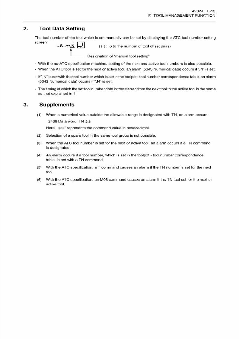
8/15/2019 Okuma Manuals 391
http://slidepdf.com/reader/full/okuma-manuals-391 194/397
4202-E
F-15
F.
TOOL MANAGEMENT FUNCTION
2.
Tool Data Setting
The tool number of the tool which
is
set
manually
can be
set
by
displaying
the AT C tool
number
setting
screen.
=5-**ÿ
[j]
(;F:<:
0
to
the
number of tool offset pairs)
L_
Designation
of
“manual
tool
setting”
-
With the no-ATC
specification
machine, sett ing
of the next
and
active tool numbers
is
also
possible.
-
When the
AT C
tool
is
set for the next or active
tool, an
alarm
(5343
Numerical
data) occurs if “,N” is
set.
-
If
“,N”
is
set with the tool number which is set
in
the
toolpot
-
toolnumber
correspondence table,
an alarm
(5343
Numerical
data)
occurs
if “,N” is
set.
-
The
timing
at which theset tool number data
is
transferred from
the
next tool tothe active tool
is
the same
as that
explained
in 1.
3.
Supplements
0)
When
a numerical
value outside
the
allowable range
is
designated
with
TN ,
an
alarm occurs.
2438
Data
word: TN
*> ;
Here,
represents
the
command value
in hexadecimal.
(2)
Selection of a
spare
tool
in
the
same
tool
group
is not
possible.
(3) When the
AT C
tool number
is
set for the next
or
active
tool,
an alarm occurs
if
a
TN
command
is
designated.
An
alarm
occurs
if
a
tool
number,
which is set
in the
toolpot
-
tool number correspondence
table,
is set with
a
TN
command.
(4)
With
the
ATC specification, a
T
command causes an alarm
if
the
TN
number
is
set for
the
next
tool.
(5)
(6) With
the ATC
specification,
an
M06
command causes an alarm if
the
TN
tool set for the
next or
active
tool.

8/15/2019 Okuma Manuals 391
http://slidepdf.com/reader/full/okuma-manuals-391 195/397

8/15/2019 Okuma Manuals 391
http://slidepdf.com/reader/full/okuma-manuals-391 196/397
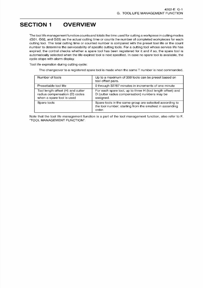
8/15/2019 Okuma Manuals 391
http://slidepdf.com/reader/full/okuma-manuals-391 197/397
4202-E G-1
G. TOOL
LIFE
MANAGEMENT FUNCTION
SECTION
1
OVERVIEW
The tool
life
management
function counts
and
totals
the
time
used
for
cutting
a
workpiece
in cutting
modes
(G01
,
G02, and
G03)
as the actual
cutting
time
or
counts the number
of
completed
workpieces
for each
cutting tool.
The
total
cutting
time
or
counted
number
is
compared
with
the
preset
tool
life
or
the
count
number
to determine the
serviceability
of
specific
cutting
tools.
For a
cutting
tool
whose
service life has
expired,
the
control
checks
whether
a spare tool
has been
registered for
it
and
if so ,
the
spare tool
is
automatically
selected when the
life-expired
tool is next
specified.
In
case no
spare
tool is
available,
the
cycle
stops
with
alarm display.
Tool life
expiration
during cutt ing cycle:
The
changeover
to
a
registered
spare
tool
is made
when the same
T
number
is next
commanded.
Number
of tools
Up
to a maximum of
300
too ls can
be
preset
based
on
tool
offset
pairs.
Presettable
tool l ife
0
through
32767 minutes
in
increments of one minute
Tool
length
offset
(H)
and
cutter
radius
compensation
(D)
codes
when
a
spare
tool is used
Fo r each
spare tool, up
to three
H (tool length offset)
and
D
(cutter
radius
compensation)
numbers
may
be
assigned.
Spare
tools
Spare
tools
in
the
same group
are selected
according
to
the tool
number; starting
from the smallest
in
ascending
order.
Note that the tool life
management
function is
a
part
of
the tool
management function,
also
refer
to
F.
“TOOL MANAGEMENT FUNCTION”.
8/15/2019 Okuma Manuals 391
http://slidepdf.com/reader/full/okuma-manuals-391 198/397
4202-E
G-2
G. TOOL
LIFE
MANAGEMENT FUNCTION
SECTION 2 ENTRY OF TOOL
LIFE
MANAGEMENT
DATA
The tool life
management
data
is
set
in
the
following sequence.
Setting
Procedure:
(1)
Set the tool number for a toolpot number.
(2)
Group
the tools.
(3)
Se t
the
management
mode.
(4)
Enter
the
tool life
data
-
SE T
TIME
an d
LEFT TIME.
When
the tool
life
is
counted
in
terms
of
“time”,
the tool
life
should
be set
in
minutes and
seconds,
and
when
it
is determined
by
the
“number
of
finished
workpieces”,
the tool life should
be set
as
the
number
of
workpieces that can be f inished before the tool life
expires.
(5)
When the second and the th ird
offset
data are to be
used,
set
the
offset
numbers
for
them
individually.
The command “TLFON”
programmed
after
the
above setting, starts
the
tool life
management.
The data
setting
procedure
for individual steps
(1
)
through
(4)
are explained in details. For step
(5),
refer
to
Part
I,
“Tool
Management
Function”
-
Enter toolnumbers
corresponding
to the
pot
number in the
ATC POT NO .
/TOOL
NO . TABLE since
the
tool
life is monitored for individual tools.
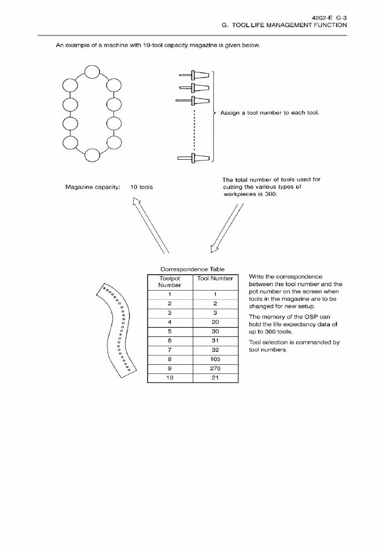
8/15/2019 Okuma Manuals 391
http://slidepdf.com/reader/full/okuma-manuals-391 199/397
4202-E G-3
G. TOOL
LIFE
MANAGEMENT FUNCTION
An
example of a machine with 10-tool
capacity magazine
is
given
below.
Assign
a
tool
number to each
tool.
£=[t=lJ
The total number
of tools
used
for
cutting
the
various types
of
workpieces
is 300.
Magazine
capacity:
10 tools
Correspondence
Table
Write the
correspondence
between the
tool
number and the
pot
number
on
the screen when
tools in the
magazine are to
be
changed
for new
setup.
The
memory of the OSP can
hold
the
life
expectancy
data of
up
to
300
tools.
Tool selection
is
commanded
by
tool numbers.
Toolpot
Number
Tool Number
V
1 1
o
2 2
3
3
4
20
o
5
30
o
6
31
O
7
32
O
O
8 10 5
O
9
270
10
21
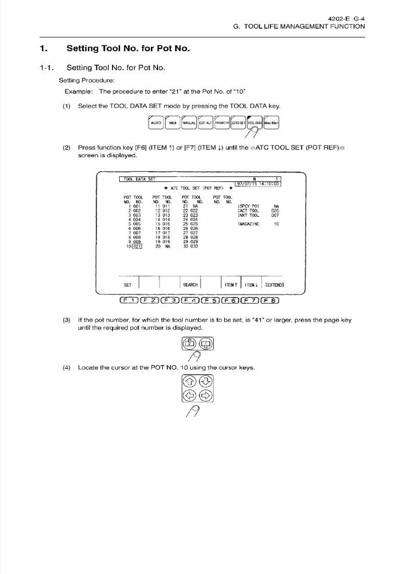
8/15/2019 Okuma Manuals 391
http://slidepdf.com/reader/full/okuma-manuals-391 200/397
4202-E
G-4
G. TOOL
LIFE
MANAGEMENT FUNCTION
1
. Setting
Tool
No. for Pot No.
1-1 .
Setting
Tool No.
fo r Pot No.
Setting Procedure:
Example:
The procedure
to enter “21
at the Pot No.
of
“10”
(1)
Select the
TOOL DATA
SET mode
by pressing the
TOOL
DATA key.
lÿAUTO j
j ÿMDI
j
IÿANUAI j Aliij
jpAflMETfflj jzERQ
S T|ÿQÿ T J
jljac Manj
(2)
Press
function
key
[F6]
(ITEM
f)
or [F7]
(ITEM
|) until
the
*ATC
TOOL
SE T
(POT
REF)*
screen is
displayed.
I
TOOL
DATASET
N
1
197/07/15
14:10:00
*
ATC
TOOL
SE T
(POT REF)
*
P OT T OO L
NO. NO.
P OT T OO L
NO.
NO .
11
011
12
012
13
013
14
014
15
015
16 016
17
017
18 018
19
019
20
NA
POT TOOL POT
T00L
N0. NO .
NO.
NO .
21
NA
22 022
23 023
24
024
25 025
26
026
27
027
28 028
29 02 9
30
030
1 001
:SPCY PO T
:
ACT TOOL
:NXT TOOL
NA
2
002
3 003
4
004
5 005
6
006
7 007
8 008
02 0
007
:MAGAZINE
10
9
009
10l02i1
ITEM
I
[EXTEND]
ET
SEARCH
ITEM t
[F~1
)(F
2}(F~3J[F
<1
)PHTlPHn(T'TirF~Fl
(3) If
the
po t
number,
for
which the tool number
is
to be
set,
is
“41”
or
larger, press
the page
ke y
until the
required pot
number
is
displayed.
(4)
Locate
the
cursor
at
the
PO T NO.
1
0
using
the cursor
keys.
©©
@@
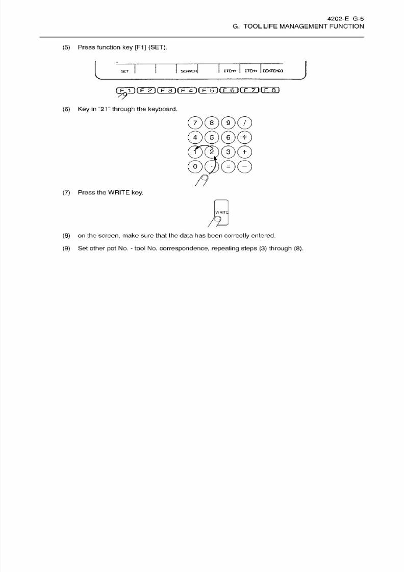
8/15/2019 Okuma Manuals 391
http://slidepdf.com/reader/full/okuma-manuals-391 201/397
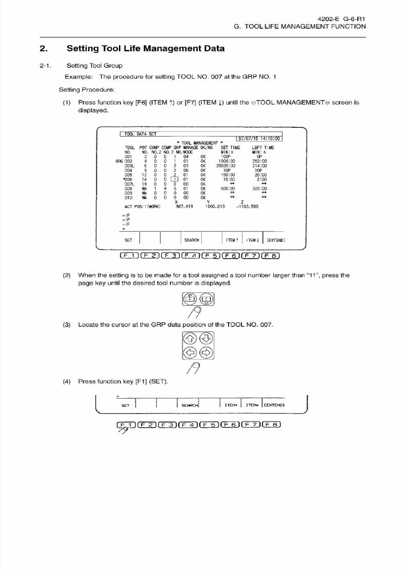
8/15/2019 Okuma Manuals 391
http://slidepdf.com/reader/full/okuma-manuals-391 202/397
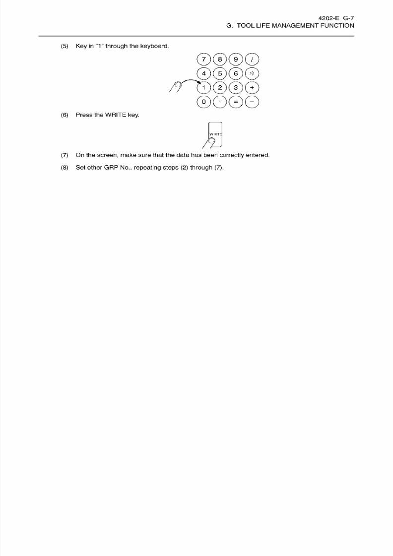
8/15/2019 Okuma Manuals 391
http://slidepdf.com/reader/full/okuma-manuals-391 203/397
4202-E G-7
G. TOOL
LIFE
MANAGEMENT FUNCTION
(5)
Key in “1
”
through
the
keyboard.
0®@©
12 3
+
(6) Press the
WRITE
key.
WRITE
(7) On the
screen,
make sure that the
data
has been
correctly
entered.
(8)
Set
other
GRP
No., repeat ing
steps
(2 )
through
(7).
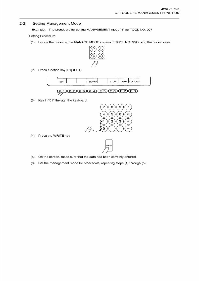
8/15/2019 Okuma Manuals 391
http://slidepdf.com/reader/full/okuma-manuals-391 204/397
4202-E G-8
G. TOOL
LIFE
MANAGEMENT FUNCTION
2-2. Setting
Management
Mode
Example:
The
procedure
for
setting
MANAGEMENT mode
“1 ”
for
TOOL NO.
007
Setting
Procedure:
(1)
Locate
the
cursor
at the
MANAGE MODE
column
of
TOOL NO.
007
using
the
cursor
keys.
©©
©@l
(2)
Press
function
key
[F1]
(SET).
L
J
te m
j
ITETH
|
[EXTEND]
SEARCH]
ET
rFÿrnÿnÿrrÿfFÿrFÿrFrirrs)
79
(3)
Key
in
‘‘01
”
through
the
keyboard.
©®@©
©©©©
j©©@©
0
(4)
Press the
WRITE key.
WRITE
/©
(5)
On the
screen,
make sure that the data has been
correctly
entered.
(6)
Set
the
management
mode for
other
tools, repeating
steps (1) through
(5).
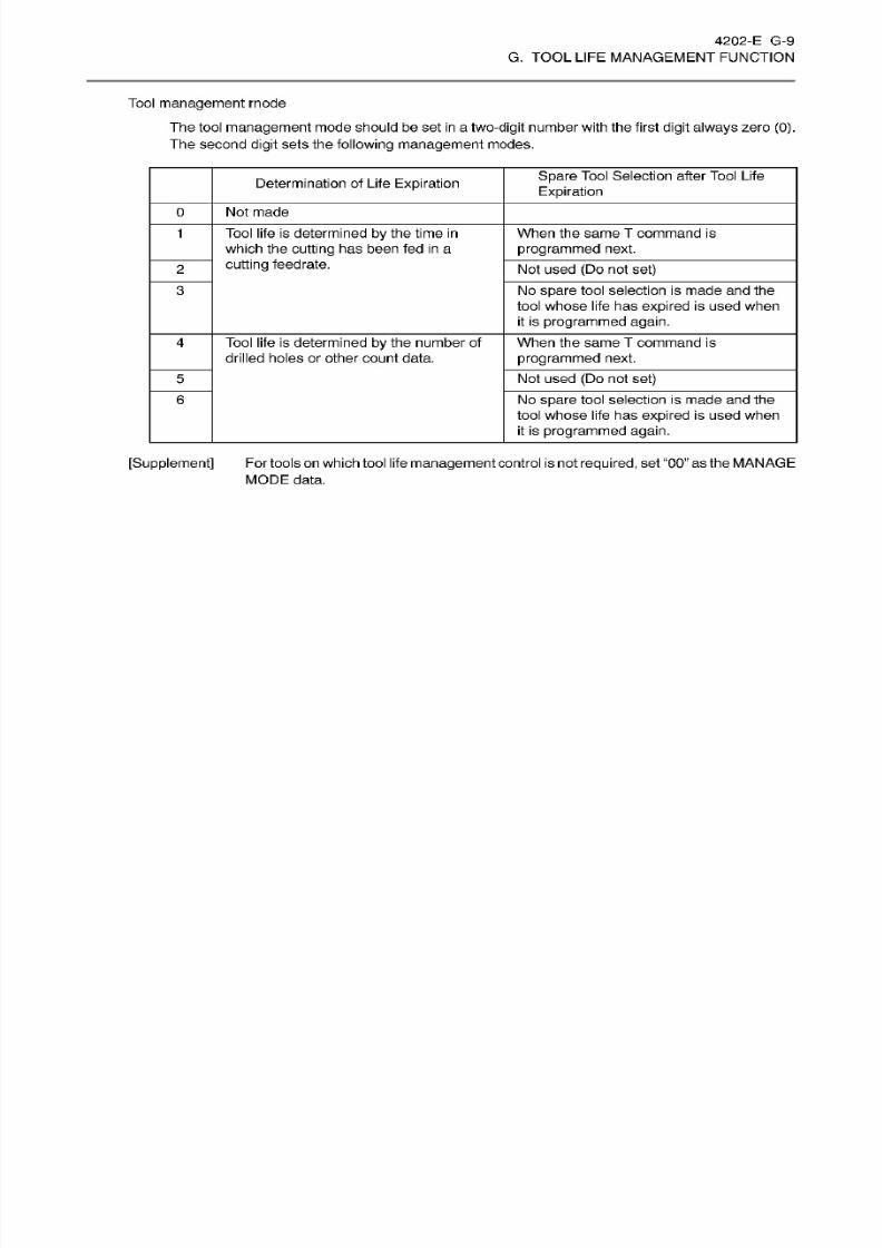
8/15/2019 Okuma Manuals 391
http://slidepdf.com/reader/full/okuma-manuals-391 205/397
4202-E G-9
G. TOOL
LIFE
MANAGEMENT FUNCTION
Tool
management
mode
The tool
management
mode should be set
in
a
two-digit
number with the first
digit always
zero
(0).
The second
digit
sets
the following
management
modes.
Spare
Tool
Selection after
Tool
Life
Expiration
etermination
of
Life
Expiration
Not made
Tool life is determined
by the time
in
which the
cutting
has been fed
in
a
cutting
feedrate.
When the
same T command is
programmed
next.
1
Not
used (Do not set)
No
spare
tool
selection
is
made an d
the
tool whose life has
expired
is
used
when
it
is
programmed
again.
3
Tool life
is
determined
by the
number
of
drilled holes or other
count
data.
When
the same
T
command
is
programmed
next.
4
No t
used
(D o
not
set)
No
spare
tool selection is made and the
tool
whose life
has expired
is
used
when
it
is
programmed again.
6
[Supplement]
For tools on which tool life
management
control isnot
required,
set
“00”
asthe MANAGE
MODE data.
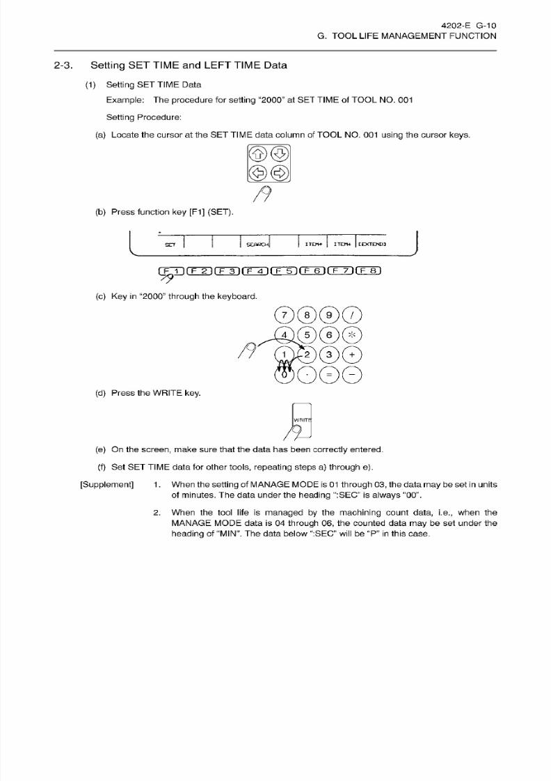
8/15/2019 Okuma Manuals 391
http://slidepdf.com/reader/full/okuma-manuals-391 206/397
4202-E G-10
G. TOOL
LIFE
MANAGEMENT FUNCTION
2-3.
Setting
SET
TIME
and
LEFT TIME
Data
(1)
Setting
SET
TIME
Data
Example:
The
procedure
for
setting
“2000”
a t S ET
TIME
of TOOL
NO.
001
Setting
Procedure:
(a)
Locate the cursor at the SE T
TIME
data column of TOOL NO . 001
using
the cursor keys.
©©
©@l
(b)
Press function
key
[F1]
(SET).
L
J
TEm
|
ITEru
|
[EXTEND]
SEARCH]
ET
fF©T
fF~ÿ
[~F~3l f~F~4~)
f~F~5l l~F~6T
t~Fÿ7l
(~F~8l
79
(c) Ke y in
“2000”
through
the keyboard.
0®®0
00®®
£)®0
O0O
(d)
Press the
WRITE key.
WRITE
(e)
On the
screen,
make sure
that
the
data ha s been
correctly
entered.
(f)
Set
SET TIME
data for other tools,
repeating
steps
a)
through
e).
[Supplement] 1
.
When
the setting
of
MANAGE MODE is
01
through 03, the
data
may be
set in
units
of minutes. The data under the
heading “:SEC”
is
always
“00”.
2. When the tool life
is
managed by
the
machining
count
data, i.e.,
when the
MANAGE
MODE data
is
04
through
06,
the counted data
may
be set under the
heading
of
“MIN”.
The data below “:SEC”
will
be
“P ” in
this case.
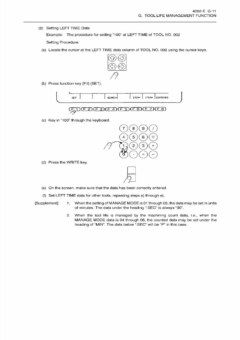
8/15/2019 Okuma Manuals 391
http://slidepdf.com/reader/full/okuma-manuals-391 207/397
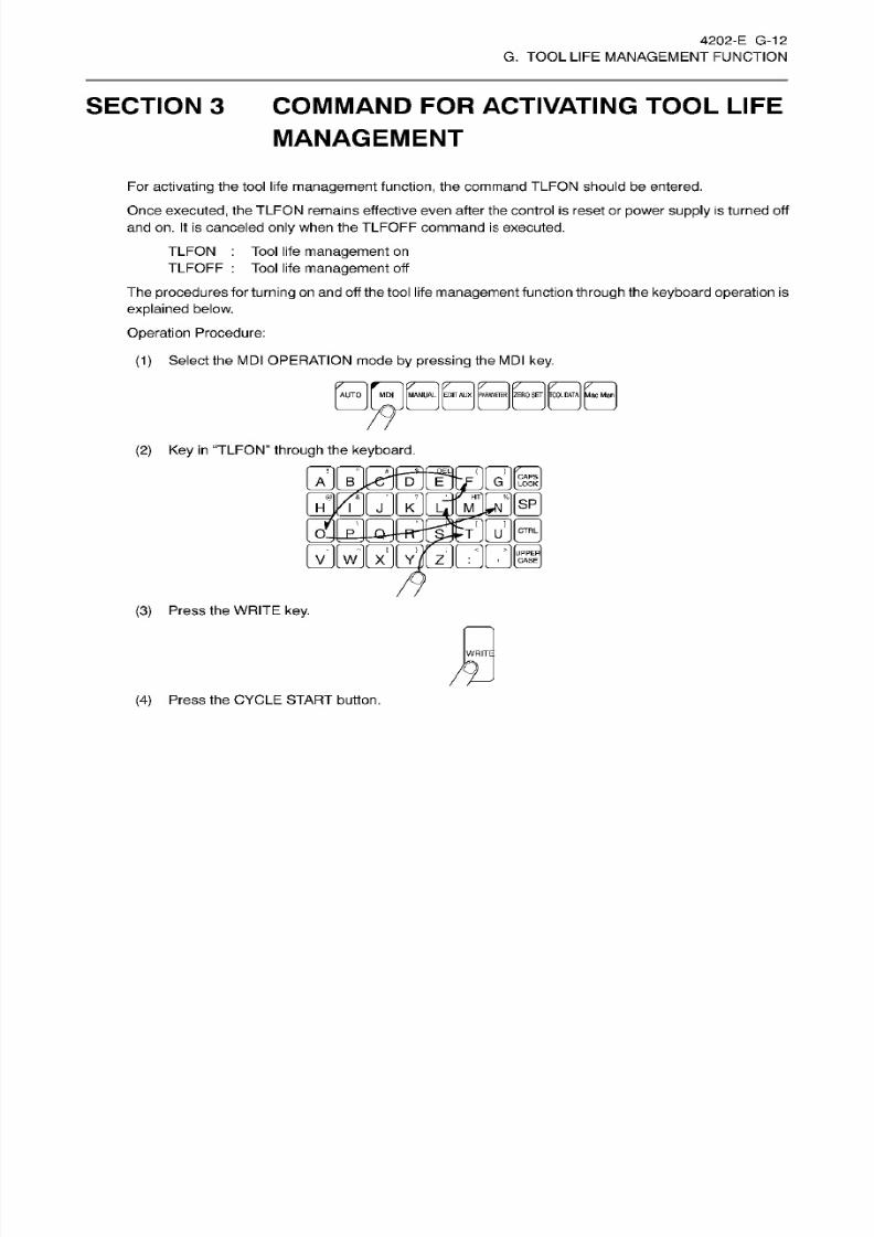
8/15/2019 Okuma Manuals 391
http://slidepdf.com/reader/full/okuma-manuals-391 208/397
4202-E G-12
G. TOOL
LIFE
MANAGEMENT FUNCTION
SECTION 3
COMMAND
FOR ACTIVATING
TOOL LIFE
MANAGEMENT
For
activating
the
tool
life
management
function,
the
command TLFON should be entered.
Once
executed,
the TLFON remains
effective even after
the control is reset or
power
supply
is
turned
off
and on. It is canceled only when the TLFOFF command is
executed.
TLFON
Tool
life
management
on
TLFOFF
: Tool life
management
off
The
procedures
for
turning
on and
off
the tool life
management
function
through
the
keyboard operation
is
explained
below.
Operation
Procedure:
(1)
Select the
MDI
OPERATION mode
by pressing
the
MDI key.
IÿAUTO
j
p
MDI
j
pmUAI jpr/mxj pMliEIERj
pR O
SElj j rOOL
PAJa| jta:
Manj
//
(2)
Key
in
“TLFON”
through the keyboard.
SSB
W~/
H
V\
(
D E
3®
G)@
o.
T
(3)
Press the WRITE key.
WHITE
(4)
Press the
CYCLE
START
button.
8/15/2019 Okuma Manuals 391
http://slidepdf.com/reader/full/okuma-manuals-391 209/397
4202-E G-13
G. TOOL
LIFE
MANAGEMENT FUNCTION
[Supplement] 1
.
Fo r
tools
for which tool life
management
control
is
not required,
set
“00”
as
the
MANAGE
MODE
data.
2.
Fo r tools
for
which automatic
spare tool
selection is not
desired,
set
“0”
at the GRP
NO. data. With
this
setting, only
the tool
life
management
is
accomplished
and
the
T
command
calling
the tool whose life has
expired
sets the commanded tool in the
spindle.
The action that
follows
depends
on
the setting
of the
MANAGE DATA.
3 or 6
____
utting is continued.
1 or
4 ....
Alarm
occurs.
(Alarm message:
Active tool
NG3)
3.
When the tool life
management
is
carried out
in
terms of
a count
number,
the
command
TLCO
should
be used
in
addition to
the command TLFON. The manner
for
entering
the TLCO
command
is
explained
on
the
fol lowing page.
Operation
Procedure:
(a)
Press the
MDI key.
(b) Key-in
“TLCO
Qxxx”
through
the
keyboard.
Flere, “xxx”
indicates
the
number
to be deducted
from
the set count
data. I ts range is
from 0
to 999.
(c)
Press
the
WRITE key.
(d)
Press the
CYCLE START
button.
-
When
this
command
is
given
while
the
management
mode
of
the
tool
in
the
spindle
is
“count”,
the number
entered following
the
address character
Q is
deducted from the
LEFT TIME
data
of that tool.
-
In
case
no
number is
specified
following
“Q”,
then the data
is counted down
by
on e
(1).
-
The
TLCO
command is not a modal command. That
is,
the deduction
or
counting
down
is
made only
when
it
is
commanded.
The
explanations
of
the commands used in the tool
life
management
function,
such
as
TLFON,
TLFOFF
an d
TLCO, ha ve bee n given assuming the MDI mode
operation.
In
the automatic mode operation, these commands
may
be issued
in
the
same
manner.
8/15/2019 Okuma Manuals 391
http://slidepdf.com/reader/full/okuma-manuals-391 210/397
4202-E G-14
G. TOOL
LIFE
MANAGEMENT FUNCTION
SECTION 4
RESETTING
TOOL
LIFE DATA
1.
For Usable Tools
Fo r
tools
whose
preset
tool life
has
expired
bu t the
operator
has judged
that
it
can
be
still
used for
cutting,
change
the
tool life data
using
the following
procedure.
Setting
Procedure:
(1)
Select the TOOL
DATA
SET mode
by pressing the
TOOL
DATA key.
(2)
Press function
key
[F6]
(ITEM f) or [F7]
(ITEM
|)
until the screen
displays
the
*TOOL
MANAGEMENT*
screen.
(3)
Following
the step
(2)
in 2-2-3,
enter
the expected
remaining
l ife as the
LEFT TIME
data.
(4)
Locate
the cursor
at
the
OK/NG
column
using
the
cursor
keys.
(5)
Press function
ke y [F1] (SET).
(6)
Ke y
in
“OK
through
the
keyboard.
(7)
Press the WRITE key.
(8)
On
the
screen,
make sure that the data ha s been
correctly
entered.
Example:
SET
TIME LEFT TIME
100:00 -5:28
If an
operator
has
judged
that the
tool
is
stil l usable
for additional 30
minutes,
the
setting should
be :
SET TIME LEFT TIME
100:00 30:00
8/15/2019 Okuma Manuals 391
http://slidepdf.com/reader/full/okuma-manuals-391 211/397
4202-E
G-15
G. TOOL
LIFE
MANAGEMENT FUNCTION
2.
Changing
a
Life-expired
Tool with
New One
The
LEFT T IME
data
must be
reset
after
exchanging
the
life-expired
tool
with a
new
tool.
Follow the
procedure
below
for
resetting
the
data.
Setting
Procedure:
Set the tool length offset and cutter
radius compensation
data of the
new
tool first.
For
the
setting
procedure,
refer to Section 4-1. “Tool
Length
Offset and
Cutter
Radius
Compensation’’
in Section 1 .
Press function key [F6]
(ITEM
t)
or
[F7] (ITEM
J,)
until the screen
displays the
*TOOL
MANAGEMENT:;;
screen.
(1)
(2)
Following
the steps
in
Section
2-2-3,
set the tool
life
data
in
terms of time or count number
depending on
the MANAGE MODE
setting at the
SE T
TIME
and
LEFT TIME
data.
In case
the SE T
TIME
data
is
the
same
as the
one previously entered, then
the data
only for the
LEFT TIME
should be
entered.
(3)
(4)
Locate the cursor to the
NG/OK
column
using
the
cursor
keys.
(5) Press function
ke y
[F1]
(SET).
(6)
Key
in
“OK”
through
the
keyboard.
(7) Press the
WRITE
key.
(8)
On
the
screen,
make
sure
that
the data has been entered correctly.
Example:
SE T
TIME LEFT TIM E
50:00
-3:14
In
case the SET
TIME
data
is
the same as the one
previously
set,
the
setting
should be:
SET
TIME LEFT
TIME
50:00 50:00
3.
Setting
LEFT TIME
Data
to the Same Value
as SET
TIME
Data
for
All
Tools
Setting Procedure:
(1)
Press
the
MDI key.
(2)
Enter the
command TLFR through
the
keyboard.
(3)
Press the
WRITE key.
(4)
Press
the
CYCLE START button.
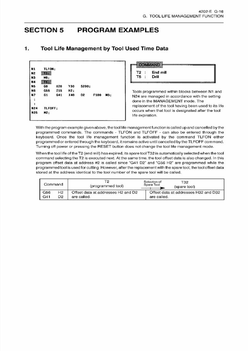
8/15/2019 Okuma Manuals 391
http://slidepdf.com/reader/full/okuma-manuals-391 212/397
4202-E G-16
G. TOOL
LIFE
MANAGEMENT FUNCTION
SECTION 5
PROGRAM
EXAMPLES
1. Tool
Life Management
by Tool
Used Time
Data
N1 TLFON;
T2
:
End
mill
T5
:
Drill
N2
N3 M6;
N4
NS GO X20 Y30
S200;
N6 G56
Z1S
H2;
N7
G1
G4 1
X40 D2
FIDO
H3;
Tools
programmed
within blocks between N1 and
N24
are
managed in
accordance
with
the
setting
done
in
the MANAGEMENT mode.
The
replacement
of
the
tool
having
been
used
to
its
life
occurs
when
that
tool
is
designated
after
the
tool
life
expiration.
:
:
N2 4 TLFOFF;
N25 M2;
With the
program example
givenabove,
thetool life
managementfunction
is called
up
and cancelled
by
the
programmed
commands.
The
commands
-
TLFON and
TLFOFF
-
can also be entered through the
keyboard. Once the tool
life
management
function is activated by the command
TLFON
either
programmed
or
entered through
the
keyboard, it
remains active until cancelled
by
the TLFOFF command.
Turning
off power or pressing
the
RESET
button does
not
change the tool l ife management
mode.
When the tool life of the T2
(end mill)
ha s
expired,
its
spare
tool
T3 2 is automatically
selected when the
tool
command
selecting the T2
is executed next.
At
the
same
time, the tool offset data is also
changed. In
this
program
offset data
at
address
#2
is
called
since
“G41
D2”
and “G56 H2”
are
programmed
while
the
programmed
tool is used for
cutting. Flowever,
after the replacementwith
the
spare
tool,
the
tool offset data
stored at the address identical to the tool number of the
spare
tool
will
be called.
T2 Selection
of
Spare
Tool
T3 2
Command
(programmed tool)
(spare
tool)
G56 H2
G41
D2
Offset
data
at addresses
H2
and
D2
are
called.
Offset data at addresses H32 and D32
are called.
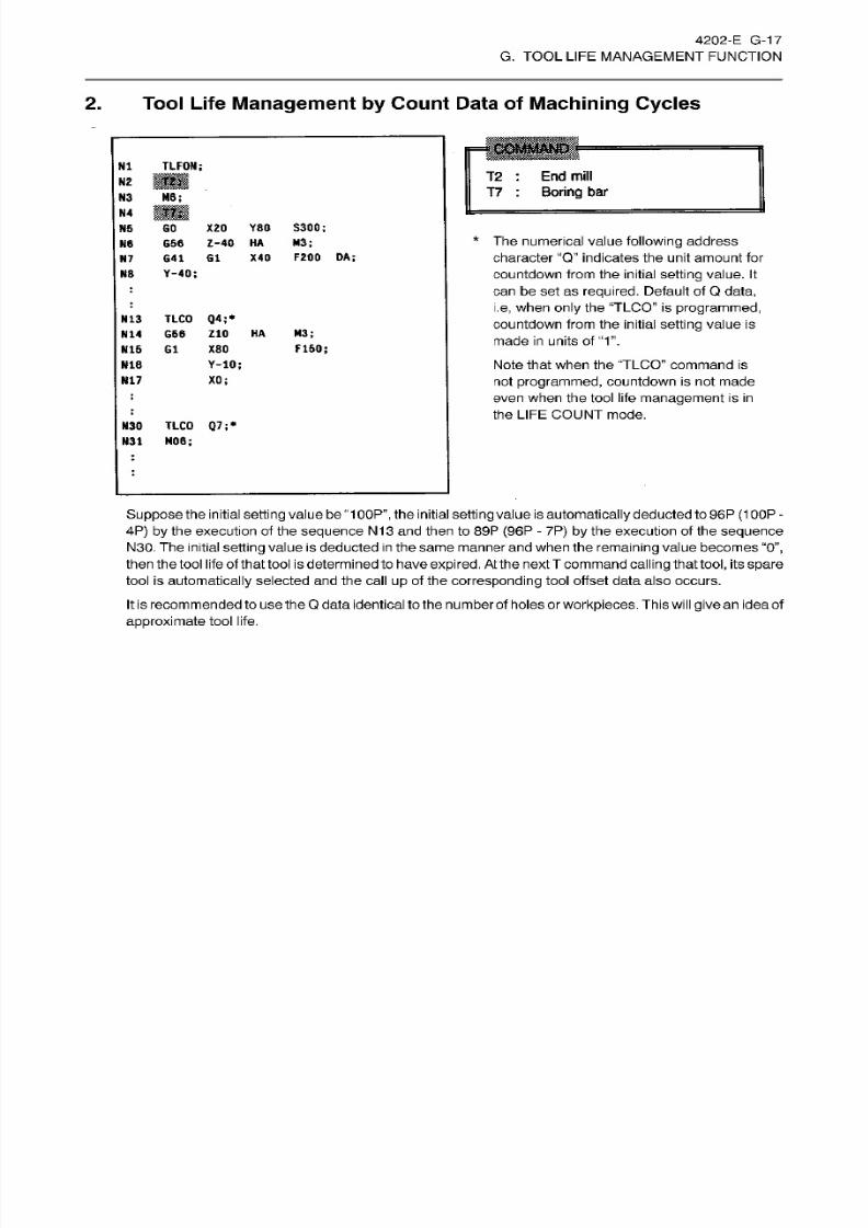
8/15/2019 Okuma Manuals 391
http://slidepdf.com/reader/full/okuma-manuals-391 213/397
4202-E G-1
7
G. TOOL
LIFE
MANAGEMENT FUNCTION
2.
Tool Life
Management
by Count
Data
of Machining
Cycles
COMMAND
N1 TLFON;
T2
:
End
mill
T7
:
Boring
bar
N2
M6 ;
3
N4
GO
X20
Y8 0
S300;
G56
Z-40
HA
M3;
G41
G1
X4 0 F200
DA;
Y-40;
N5
*
The numerical value
following
address
character
“Q”
indicates the unit amount for
countdown from the initial
setting
value.
It
can
be
set as
required.
Default of Q
data,
i.e,
when
only
the
'TLCO” is
programmed,
countdown from the
initial setting
value
is
made in
units
of
“1”.
Note that
when
the
TLCO”
command
is
not
programmed, countdown
is
not
made
even when the tool
life
management
is
in
the
LIFE
COUNT mode.
N7
N8
:
:
TLCO
Q4;*
G56
Z10
HA M3;
F150;
N13
N1 4
N15 G1
X80
Y-10;
16
N17
XO;
:
:
TLCO
Q7;*
30
M06;
31
:
:
Suppose
the initial
setting valuebe “100P”, the
initial
setting value
is
automatically deducted
to
96P
(1OOP
-
4P) by
the execution of the
sequence
N13 and then to 89P
(96P
-
7P) by
the execution of the sequence
N30.
The initial setting value is deducted
in
the
same manner
and
when
the remaining value becomes
“0”,
then
the
tool
life
of
that
tool isdetermined
to have
expired.
At
the nextT
command
calling
thattool,
its
spare
tool is
automatically
selected and
the
call
up
of
the corresponding
tool offset data also occurs.
It
is recommended to use the Q data identical tothe number of holes or workpieces. This
will give an
ideaof
approximate
tool life.
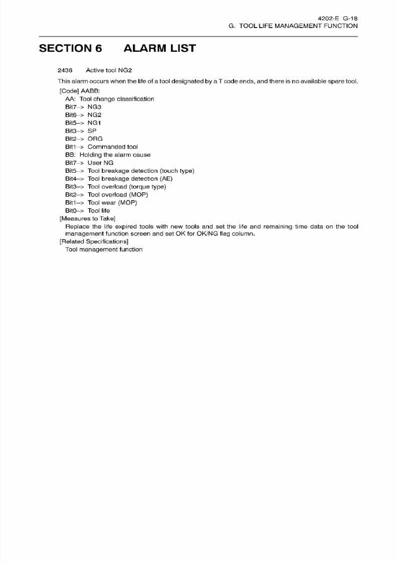
8/15/2019 Okuma Manuals 391
http://slidepdf.com/reader/full/okuma-manuals-391 214/397

8/15/2019 Okuma Manuals 391
http://slidepdf.com/reader/full/okuma-manuals-391 215/397
H.
PPC
(PALLETE
POOL
LINE
CONTROL)
FOR HORIZONTAL
MC
MULTI-PLANE APC
(FOR
MX
SERIES)
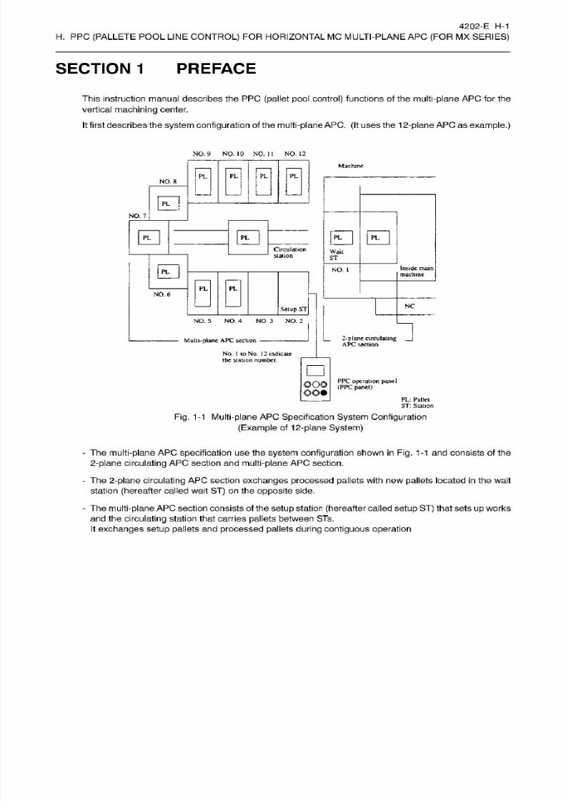
8/15/2019 Okuma Manuals 391
http://slidepdf.com/reader/full/okuma-manuals-391 216/397

8/15/2019 Okuma Manuals 391
http://slidepdf.com/reader/full/okuma-manuals-391 217/397
4202-E
H-2
H.
PPC
(PALLETE
POOL
LINE
CONTROL)
FOR HORIZONTAL MC MULTI-PLANE AP C
(FOR
MX
SERIES)
- The
circulating
station of the multi-planeAPC
section,
pallet
carry-in
from the
setup ST
toeach
ST,
pallet
carry-out
from each ST to the
setup
ST
can
be controlled
from the
operat ion panel
called
PPC
panel.
-
The
2-plane
circulating
APC section and
machining scheduling can
be controlled from the NC
operation
panel
of the machine.
-
The above
system
allows
for
long-time
continuous
processing
with
operator
or
without
operators
according
to
machining
schedules.

8/15/2019 Okuma Manuals 391
http://slidepdf.com/reader/full/okuma-manuals-391 218/397
4202-E
H-3
H.
PPC
(PALLETE
POOL
LINE
CONTROL)
FOR HORIZONTAL MC MULTI-PLANE AP C
(FOR
MX
SERIES)
SECTION 2 PPC
CYCLE
OPERATION
PROCEDURES
Fo r
executing
PPC
cycle
operation on
the
system,
fol low the
procedures
shown below.
(1)
Create the
PPC
cycle
operation
machining program.
(Section 3.)
1
(2)
Assign
PP C
cycle
operation
machining
programs
to pallet
numbers.
(Section
7.)
I
(3)
Carry
in
and out
pallets
to and from each ST.
(Section
5
and 6.)
I
(4)
Edit
machining
schedules.
(Section
8.)
I
Start

8/15/2019 Okuma Manuals 391
http://slidepdf.com/reader/full/okuma-manuals-391 219/397
4202-E
H-4
H.
PPC
(PALLETE
POOL
LINE
CONTROL)
FOR HORIZONTAL MC MULTI-PLANE AP C
(FOR
MX
SERIES)
SECTION 3 CREATING
THE
MACHINING
PROGRAM
FOR PPC
CYCLE
OPERATION
For PPC
cycle
operation,
the
user
must create two
kinds
of
dedicated
machining
programs.
-
Pallet
exchange machining
program
-
PPC
cycle
operation
machining
program
1. Creating
the Pallet
Exchange
Machining
Program
Create the
circulation
program
for
the
2-plane
circulating
APC on
the
machine
as
shown
below and
store
it
into
MD1:.
Filename: PPC9999.MIN
Contents:
0????
where
????
indicates
any
name.
2-plane
circulating
AP C
circulation
instruction
Program
end instruction
M160
M02
2.
Creating
the
PPC Cycle
Operation
Machining
Program
Create
the
PP C
cycle
operation machining program
as
shown
below
and
store it
into
MD1 :.
File
name:
PPC?????????????.
MIN
(?...
indicate
an y name.)
where ????
indicates
any
name.
ontents:
O????
[Process]
M02
Program end
instruction
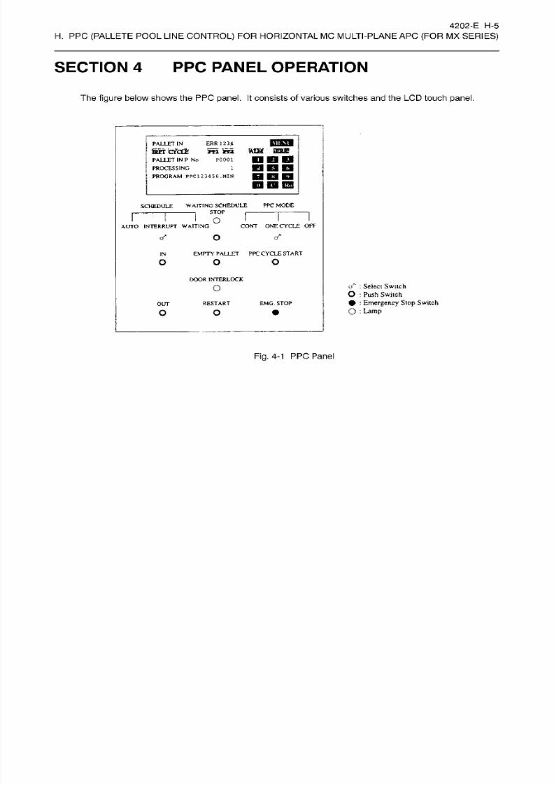
8/15/2019 Okuma Manuals 391
http://slidepdf.com/reader/full/okuma-manuals-391 220/397
4202-E
H-5
H.
PPC
(PALLETE
POOL
LINE
CONTROL)
FOR HORIZONTAL
MC
MULTI-PLANE AP C
(FOR
MX
SERIES)
SECTION
4 PPC PANEL OPERATION
The figure
below
shows
the PP C
panel. It
consists of
various switches
and
the
LCD
touch
panel.
pun
me
PALLET
IN
fePT
cVcLfe
PALLET
INP
No
PROCESSING
PROGRAM
PPC123456.MN
ERR
123.4
*ri
re t
P0001
1
Q
D
ns
WAITING SCHEDULE
PP C MODE
STOP
|
—
-
—
SCHEDULE
o
CONT
ONE
CYCLE
OFF
UTO
INTERRUFT
WAITING
cr*
EMPTY
PALLET
PPC CYCLE
START
N
o
DOOR
INTERLOCK
:
Select
Switch
O
:
Push
Switch
•
:
Emergency Stop
Switch
O
:
Lamp
O
RESTART EMG.
STOP
UT
o
Fig.
4-1
PP C
Panel
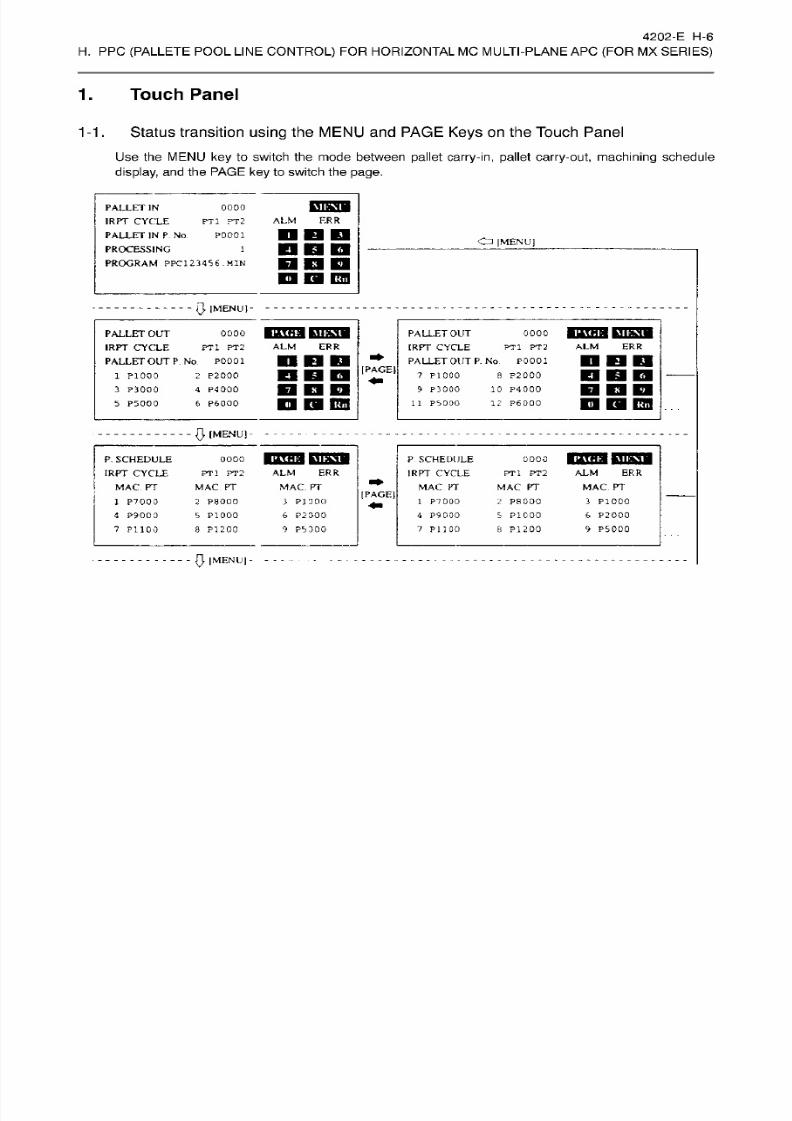
8/15/2019 Okuma Manuals 391
http://slidepdf.com/reader/full/okuma-manuals-391 221/397
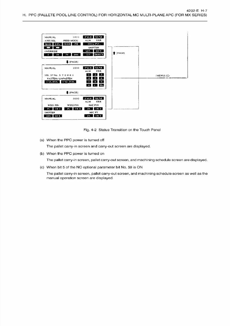
8/15/2019 Okuma Manuals 391
http://slidepdf.com/reader/full/okuma-manuals-391 222/397
4202-E
H-7
H.
PPC
(PALLETE
POOL
LINE
CONTROL)
FOR HORIZONTAL MC MULTI-PLANE AP C
(FOR
MX
SERIES)
coco
1203
EES
FEED
MODE
ALM ERR
MANUAL
AXISSEL
KffHW
m
iimiin
MUIM
ITI.K
INV.
SHIFTER
OVERRIDE
t
IPAGEI
rmgq
f
[PAGEI
oooo
fcimrn
CnSW
ALM
ER R
MANUAL
D D E S
EL
ST N o. S
T
0
0
0
I
FASTEN
/
UNFASTEN
[MENU]
BOD
22
2B
ESI
HHHI91
IPlfRl
I
[PAGEI
WHHW MIMOIM
ANUAL
0000
ERRLM
M/C
PIN
SSt
PIN WSS2
PIN
M/C FT
HIFTER
M
FTTOT
21112
CSH
Fig. 4-2
Status Transition
on
the Touch Panel
(a) When the PPC power is turned off
The
pallet carry-in
screen
and carry-out
screen
are
displayed.
(b)
When
the
PPC
power
is turned
on
The
pallet
carry-in screen, pallet
carry out
screen,
an d
machining schedule
screen are
displayed.
(c)
When bit
5
of the NO
optional
parameter
bit No.
59
is ON
The
pallet carry-in
screen,
pallet
carry-out screen,
and
machining
schedule screen as well as the
manual
operation
screen are
displayed.
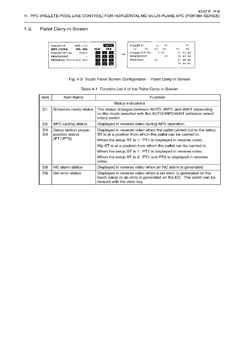
8/15/2019 Okuma Manuals 391
http://slidepdf.com/reader/full/okuma-manuals-391 223/397
4202-E H-8
H.
PPC
(PALLETE
POOL
LINE
CONTROL)
FOR HORIZONTAL MC MULTI-PLANE AP C
(FOR
MX
SERIES)
1-2.
Pallet
Carry-in
Screen
Pistil
AIM
ERA
PALLET
IN Al
B1
D2
D3 D4
PALLET
IN
P No
P
B2
PROCESSING
PROGRAM
Cl
RR
12 3*.
PTl VT2
PALLET
IN
IRPT
CYCLE
PALLET
tN
P.
No
POOC
1
PROCESSING
PROGRAM
PPC1234S6
MIN
DS
D6
1
DBD
EI
E;
EJ
E4
E5
E6
L~
ZB E9
Ea
Eb
Ec
B3
DDD
Hi
EB
rw
A2
Fig.
4-3
Touch
Panel
Screen Configuration
Pallet Carry-in Screen
Table
4-1
Function
List
2
of the Pallet
Carry-in
Screen
Item Item Name
Function
Status
indications
Schedule mode status The status
changes
between AUTO,
IRPT,
and WAIT
depending
on
the mode selected with the
AUTO/I
RPT/WAIT
schedule select
rotary
switch.
D1
D2 APC
cycling
status
Displayed in reverse
video
during
APC
operation.
D3
Setup
station
proper
position
status
(PT1/PT2)
Displayed
in
reverse
video when
the
pallet
carried out
to
the setup
ST
is
at a
position
from
which the pallet
can
be carried
in.
When
the
setup
ST is 1
:
PT1
is
displayed in reverse
video.
Wp
ST is at
a
position
from
which the pallet
can
be carried in.
When
the
setup
ST is 1:
PT 1
is
displayed
in reverse video.
When
the
setup
ST
is 2: PT 1 an d
PT2
is
displayed in
reverse
video.
D4
D5
NC alarm status
Displayed
in reverse video when an NC alarm is
generated.
Se t error status
6 Displayed in
reverse video when a set error is
generated
on the
touch
panel
or an error is
generated
on the EC. The alarm can be
cleared with the clear
key.

8/15/2019 Okuma Manuals 391
http://slidepdf.com/reader/full/okuma-manuals-391 224/397
4202-E H-9
H.
PPC
(PALLETE
POOL
LINE
CONTROL)
FOR HORIZONTAL MC MULTI-PLANE AP C
(FOR
MX
SERIES)
Table
4-2
Function List
2
of the Pallet Carry-in
Screen
Item Item Name Function
Input
keys
C1 MENU key Switches
to the
pallet carry-out
screen.
0
to 9,
Clear,
and
Return
keys
E1 Enters and
decides the
numeric value
indicating
the
pallet
number
to
carry-in
pallets.
The
Clear
key clears the
value to
“0000.”
to
Ec
Indications
Displays an
alarm or error comment
if an
NC alarm or a set error
occurs
on the PPC.
A1
Alarm
and error
comment
A2
Program
name
Displays
the
program
name of a
pallet
when a
pallet
number is
entered from the ten-key pa d
when
a
pallet
is carried in
from
the
setup
ST.
Program
name
(9
characters or
less):
PPC??????.
MIN
Program
name
(13
characters or
less):
PPC?????????
(MIN omitted)
Program name
(16
characters or
less):
????????????? (PPC/.MIN
omitted)
Only up
to 13 characters
can
be
displayed.
The
program name
is
not
displayed
when the PP C is off.
B1
Alarm and error
number
Displays the code of
an
error when
an
NC alarm or a set error
occurs
on the PPC.
NC alarm:
4
digits,
set
error:
2 digits
Carry-in
pallet
number
Displays the
pallet
number
entered from the ten-key
pad
when
a
pallet
is carried
in
from the
setup
ST .
B2
Displays
the processing order
of
a
pallet
after
a
pallet number is
entered
from the
ten-key
pad
when
a
pallet
is carr ied in
from the
setup
ST.
A
value of 0
is displayed
when the PP C
is
off.
B3 Processing
order

8/15/2019 Okuma Manuals 391
http://slidepdf.com/reader/full/okuma-manuals-391 225/397

8/15/2019 Okuma Manuals 391
http://slidepdf.com/reader/full/okuma-manuals-391 226/397
4202-E
H-11
H.
PPC
(PALLETE
POOL
LINE
CONTROL)
FOR HORIZONTAL MC MULTI-PLANE AP C
(FOR
MX
SERIES)
Table
4-4
Function List
2
of
the
Pallet Carry-out Screen
Item Item Name Function
Input
keys
C1 MENU key Switches
to
the
machining
schedule
display
screen.
02 PAGE
key
Switches
the
next page o f
the
setup
SE T
pallet carry-out
screen.
After all
processed pallet
numbers are
displayed,
the screen
returns to
page
1
.
E1
0
to
9,
Clear,
and
Return
keys
Enters
and
decides
the
numeric
value
indicating
the
pallet
number
to
carry
out
pallets.
The Clear
key
clears
the
value to “0000”.
The
Clear
ke y clears
the value to
“0000.”
to
Ec
Indications
A1 Alarm
and
error
comment
Displays
an
alarm or error comment
if an NC
alarm
or a
set
error
occurs on
the PPC.
B1
Alarm
and error
number
Displays
the code of
an
erro r when an NC
alarm
or a set error
occurs
on
the PPC.
NC alarm:
4 digits,
set error:
2 digits
B4
Carry-out pallet
number
Displays the
pallet
number
entered
from
the ten-key pa d
when a
pallet
is carried out to
the setup ST.
F1
Processed
pallet
display
order
Displays
the
display
order of all
processed
pallet numbers as well
as
the
pallet
number. The number of
pairs
displayed
is the
same
as
of
the
number of
processed pallets.
A
value of 0
is displayed
when the
PP C is off.
to
F6
Processed
pallet
number
Displays
al l
processed pallet
numbers
in
order of
process
completion.
6
pairs
can be
displayed in
one
page.
(the
maximum
number
is
50
pallets.)
The number of
pages
varies
depending on
the
processed
pallet
number.
Processed
pallet
number:
up
to 6
. . .
Processed
pallet
number:
7
to
12
.. .
Processed
pallet
number:
13
to
1
8
Processed
pallet
number:
1
9
to
24
0000
is
displayed
when the PPC is off.
Fa
to
Ff
1-page
indication
2-page
indication
3-page
indication
4-page
indication
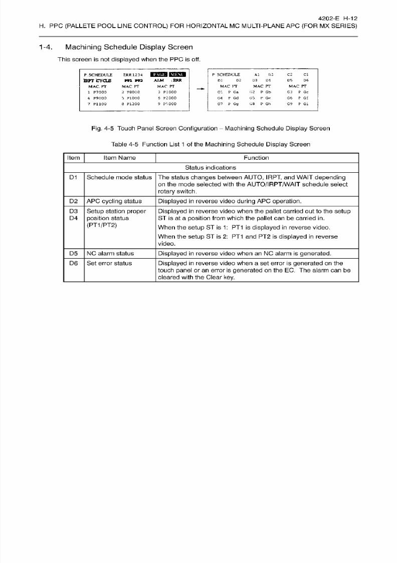
8/15/2019 Okuma Manuals 391
http://slidepdf.com/reader/full/okuma-manuals-391 227/397
4202-E
H-12
H.
PPC
(PALLETE
POOL
LINE
CONTROL)
FOR HORIZONTAL MC MULTI-PLANE AP C
(FOR
MX
SERIES)
1-4.
Machining
Schedule
Display
Screen
This
screen
is
not
displayed
when
the
PPC
is
off.
ERR
1234
HBS3KQ83S
m
rra
AIM
ERR
MAC.PT
2
?90O0
S
P1000
8 P1200
C2
SCHEDULE
Al
111 Cl
. SCHEDULE
fen*
CYCLE
MAC.
rr
1
P7000
4 P9000
7
P1100
D21 D3
O'. D5
D6
MAC PT
c.2 P Gb
C5
P
Ge
G8
P Gh
MAC.PT
G3 P
Gc
Cb
P
G£
G9
P Gi
MAC
PT
3
P1000
6
P2000
MAC
PT
G'.
P Ga
G4
P
Gd
G7
P
Go
Pr»000
Fig.
4-5
Touch
Panel Screen
Configuration
-
Machining
Schedule
Display
Screen
Table
4-5
Function
List
1
of the
Machining
Schedule
Display Screen
Item Item Name Function
Status
indications
D1
Schedule mode status The status changes
between AUTO,
IRPT,
an d
WAIT
depending
on
the mode selected
with
the
AUTO/IRPT/WAIT
schedule select
rotary
switch.
D2 APC
cycling
status
Displayed in reverse
video
during
APC
operation.
Setup
station proper
position
status
(PT1/PT2)
D3
Displayed in
reverse video when the
pallet
carried
out
to the
setup
ST
is at
a
position
from which the
pallet
can
be carr ied
in.
When
the
setup
ST
is
1:
PT 1
is
displayed in reverse
video.
When the
setup ST is
2:
P T1 a nd P T2
is
displayed in reverse
video.
D4
D5
NC alarm status Displayed in reverse video when an NC alarm is
generated.
Se t error status
Displayed in
reverse video when a set
error is generated on
the
touch panel
or an error
is
generated
on the EC. The alarm can be
cleared with the Clear
key.
D6
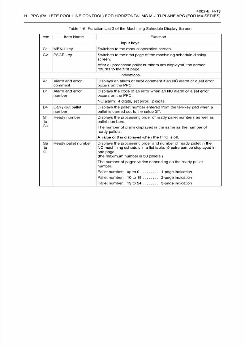
8/15/2019 Okuma Manuals 391
http://slidepdf.com/reader/full/okuma-manuals-391 228/397
4202-E H-13
H.
PPC
(PALLETE
POOL
LINE
CONTROL)
FOR HORIZONTAL MC MULTI-PLANE AP C
(FOR
MX
SERIES)
Table 4-6 Function List
2
of the
Machining
Schedule
Display
Screen
Item Item Name Function
Input
keys
C1 MENU key Switches
to
the manual
operation
screen.
02 PAGE
key
Switches to the next page of the
machining
schedule display
screen.
After al l
processed
pallet
numbers are
displayed,
the
screen
returns to the first
page.
Indications
A1
Alarm
and
error
comment
Displays an
alarm or error comment
if an
NO
alarm
or a
set
error
occurs on
the PPC.
B1
Alarm and
error
number
Displays the code
of an error
when
an
NC alarm or a set
error
occurs
on
the
PPC.
NC
alarm:
4
digits,
set
error:
2
digits
B4
Carry-out pallet
number
Displays the pallet
number
entered
from
the ten-key pa d
when
a
pallet
is carried
out
to
the setup ST.
G1 Displays
the
processing
order
of
ready
pallet
numbers as well as
pallet
numbers.
The number of p[airs
displayed
is the same
as
the
number
of
ready
pallets.
A
value of
0
is displayed
when the PPC is off.
Ready
number
to
G9
Ga
Displays the processing
order
and
number of
ready
pallet
in the
NC
machining
schedule
in
a
list
table.
9
pairs
ca n be
displayed in
one
page.
(the
maximum number is
50
pallets.)
The number
of
pages
varies
depending
on
the ready pallet
number.
Pallet
number:
up
to
9
.
Pallet number:
10
to
18
Pallet number: 1
9
to
24
Ready
pallet
number
to
Gi
1-page
indication
2-page
indication
3-page
indication

8/15/2019 Okuma Manuals 391
http://slidepdf.com/reader/full/okuma-manuals-391 229/397
4202-E H-14
H.
PPC
(PALLETE
POOL
LINE
CONTROL)
FOR HORIZONTAL
MC
MULTI-PLANE AP C
{FOR
MX
SERIES)
1-5.
Manual
Operation Screen
This
screen is
display 6. FEED
MODE
ICDSQI
AL M ERR
P\<.
MANUAL
AXIS
SEL
b
1
C2 Cl
RR 1234
FEED MODE
MANUAL
AXIS SEL
A
1
FEED MODE
DS
D6
X?
6
.K
iw.
y.2
xs
i
i:i:nl
PH
OI.
X3
y.4
SHIFTER
HIFTER
OVERRIDE
Xdc
nv.
I
KI:T.
VERRIDE
xf
8 X9 xba
Xc
nous
HI
l
1PAGE)
key
a
nm
ALM ERR.
ERR
12
34
V
\<
MANUAL
B1 C2 Cl
ANUAL
A1
D6S
El E2 E3
E4
E5 EG
BS
SEL.
ST No.
S T
0
0
0 I
FASTEN
/
UNFASTEN
SEL
ST
No
ST
FASTEN
/
UNFASTEN
Hh E7 E8 E9
g
INI.ros.
D
a
ES I
La
Eb
Ec
J.
[PACE]
key
i*\<
;i;
RR
12
34 C2 Cl
ANUAL MANUAL Al
B
1
ALM ERR
DS DS
WSS2
PIN
WSSI
PI N
Hi
Hj
SHIFTER
WSS2
PIN M/C PIN
SSI
PIN
MAC PIN
HK
HI
l
I Oil
Hm
Hn
l
I
M/C PT
/C
PT
HfFTER
r
Hd
HO
HP
e
l>\.|
KKT.
Fig.
4-6
Touch Panel
Screen
Configuration
Manual
Operation Screen
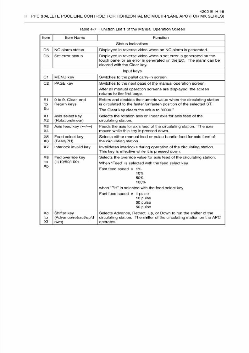
8/15/2019 Okuma Manuals 391
http://slidepdf.com/reader/full/okuma-manuals-391 230/397
4202-E H-15
H.
PPC
(PALLETE
POOL
LINE
CONTROL)
FOR HORIZONTAL MC MULTI-PLANE AP C
(FOR
MX
SERIES)
Table
4-7
Function List 1 of the Manual Operation
Screen
Item Item Name Function
Status
indications
D5
NC alarm status
Displayed
in reverse
video
when an NC alarm is
generated.
D6 Se t error status
Displayed in
reverse
video when a
set
error
is
generated
on
the
touch
panel
or an error is
generated
on the EC.
The
alarm can be
cleared with the Clear
key.
Input
keys
C1 MENU
key
Switches to the pallet
carry-in
screen.
C2 PAGE
key
Switches to the next page
of
the manual
operation
screen.
After all manual
operation
screens are
displayed,
the screen
returns to
the first page.
E1
0
to
9, Clear,
and
Return
keys
Enters
and
decides the numeric value when the
circulating station
is
circulated
to
the
fasten/unfasten
position of
the
selected
ST.
Th e
Clear
key clears
the
value
to
0000.”
to
Ec
Selects
the rotation
axis
or linear
axis for axis
feed of the
circulating
station.
X1
Axis select
key
(Rotation/linear)2
X3 Axis feed
ke y
(«-/-*)
Feeds the axis for axis feed of the
circulating
station. The
axis
moves while this
ke y is pressed
down.
4
Selects either manual feed or
pulse-handle
feed
for
axis feed of
the
circulating
station.
X5 Feed
select key
(Feed/PH)
6
X7
Interlock invalid
key
Invalidates interlocks
during
operation
of the
circulating
station.
This
ke y
is effective
while it
is
pressed
down.
X8
Fed override
key
(1/10/50/100)
Selects
the override value for
axis
feed of
the
circulating
station.
When
Feed”
is
selected
with
the feed select key
Fast feed speed
x
1%
10%
50%
100%
when PH”
is
selected with the feed select
key
Fast
feed
speed
x
1
pulse
10
pulse
50
pulse
50
pulse
to
Xb
Xc Shifter
key
(Advance/retract/up/d
own)
Selects
Advance,
Retract,
Up, or Down to run the shifter of the
circulating
station.
The
shifter
of
the circulating
stat ion on
the
APC
operates.
to
Xf
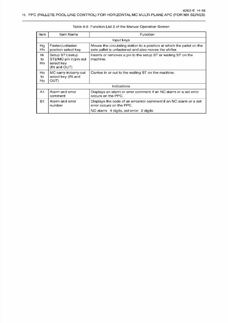
8/15/2019 Okuma Manuals 391
http://slidepdf.com/reader/full/okuma-manuals-391 231/397
4202-E H-16
H.
PPC
(PALLETE
POOL
LINE
CONTROL)
FOR HORIZONTAL MC MULTI-PLANE AP C
(FOR
MX
SERIES)
Table 4-8 Function List
2
of the Manual Operation
Screen
Item Item Name Function
Input
keys
Hg
Fasten/unfasten
position select
key
Moves the
circulating
station
to a
position
at which the
pallet
on the
sele
pallet
is
unfastened
and
also moves the
shifter.
h
Hi Setup ST1/setup
ST2/MC
pin
in/pin
out
select key
(IN
an d
OUT)
Inserts
or
removes
a pin to the
setup ST
or waiting ST on
the
machine.o
Hn
MC
carry-in/carry-out
select key (IN
and
OUT)
Carries in
or out
to the
waiting
ST on the machine.o
to
Hp
Indications
A1
Alarm and
error
comment
Displays
an alarm
or
error comment
if
an NC
alarm or a
set error
occurs
on
the
PPC.
Displays
the code of
an
erroerror
comment if an NC
alarm or a set
error
occurs
on
the
PPC.
NC
alarm:
4
digits,
set error:
2 digits
B1
Alarm
and error
number
8/15/2019 Okuma Manuals 391
http://slidepdf.com/reader/full/okuma-manuals-391 232/397
4202-E
H-17
H.
PPC
(PALLETE
POOL
LINE
CONTROL)
FOR HORIZONTAL MC MULTI-PLANE AP C
(FOR
MX
SERIES)
PPC Mode
Switch
.
Three
PPC modes
are
available:
continuous,
one
cycle,
and
off. This
section describes these PPC
modes.
Continuous
Used to run the machine
continuously according
to
the
PPC schedule.
Used to
process
one
pallet
only
of a PPC schedule.
Used
to disable PPC schedules.
One
cycle
Off
-
If
the
operation
mode is
changed
to PPC ON
(continuous/one cycle)
or PPC OFF
by
the PP C MODE
switch on the PP C
panel, both the
PPC side
and NC
side are reset.
Schedule Switch.
The PPC
schedule
registration function
provides three
types of
schedules: automatic,
waiting,
and
interrupt. When pallets are carried
in,
the operator can
select either of these
types
with
this
schedule
switch to
register
various schedules for carried-in
pallets.
Automatic Schedule
-1.
Automatic
schedule
is normal
schedule.
At
pallet
carry-in, set
this
switch
to “Automatic” at
pallet
to
carry
in a
pallet,
and
the
pallet
is
added
to
the
pallet
registered
last
by
automatic schedule.
Set
the
PPC mode switch to “CONT.” or “One
cycle”
then
press
the “PPC CYCLE START
switch,
and the
machine
processes
pallets
according
to a
registered
schedule.
Waiting
Schedule
Waiting
schedule
is
used to
pallets
ready
for
processing
on the
pallet
station but
process
them later.
Set this switch to “WAITING” when
carrying in
a
pallet,
the
pallet
is
added to the
one
registered
last
by
waiting
schedule.
If
it
takes much time to
process
them and the operator
wants
to
execute
processing
at
night,
the operator
prepares pallets
on
the ST for processing and
registers
them
by
the
waiting
schedule
in advance. The
operator
sets the PPC mode switch to “CONT.”
and
presses the PPC
CYCLE
START
switch, and
the
machine
processes
those pallets
after all
pallets registered in the
automatic schedule
complete.
3-2.
Interrupt
Schedule
Interrupt
schedule
is
used
to
interrupt
any
registered
schedule
for
scheduling when urgent processing
is
required.
Set
this
switch to “INTERRUPT” when
carring in
a
pallet,
and the machine
registers i t as
the first on e
registered
by
the automatic
schedule,
unless
the
pallet
with
processing
order
1
is not processed
on the
machine
at
that t ime. At this time,
the
pallet
is
carried
into the
waiting
St.
If
pallets
are carried
in
cont iguously by
the
interrupt
schedule,
the
machine
stores
the
pallet
numbers
carried with
INTERRUPT
and
additionally
registers
them
sequentially.
If
the
operator
once
set
the
switch
to a position
other
than
INTERRUPT,
then
returns
to INTERRUPT,
a
pallet
is also
interrupted
to the
first
on e
registered by
the automatic
schedule.
Once
registered,
pallets are processed
in
the same
way
as pallets
registered
by the
automatic
schedule.
3-3.
8/15/2019 Okuma Manuals 391
http://slidepdf.com/reader/full/okuma-manuals-391 233/397
4202-E H-18
H.
PPC
(PALLETE
POOL
LINE
CONTROL)
FOR HORIZONTAL MC MULTI-PLANE AP C
(FOR
MX
SERIES)
3-4. WAITING
SCHEDULE
STOP Switch
When
the
operator
sets this switch
to ON
during
continuous
operation in
PPC
continous
mode,
the
machine stops after
processing
the pallets
in
the automatic
schedule (pallets
with
schedule
attribute
[1]).
While
this
switch
is
OFF, the
machine starts processing
the pallets in the
waiting schedule
(pallets with
schedule
attribute
[0])
after
the
automatic
schedule completes.
While
this
switch
is
ON,
the
WAITING SCHEDULE STOP lamp
lights.
4.
EMPTY
PALLET Carry-in
Switch
Press
this
switch to carry
in
pallets
to
the
pallet
station
without registering
them to
the
PP C
schedule.
5. IN Switch
Press
this switch to
register in
pallets
to a PP C
schedule,
then
carriy
in
them
from
the setup
station to the
pallet
station.
6. OUT Switch
Press
this
switch
to
carry
out processed pallets
from
the
pallet
station to
the
setup
station.
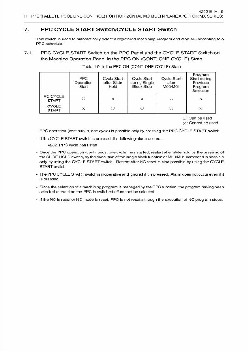
8/15/2019 Okuma Manuals 391
http://slidepdf.com/reader/full/okuma-manuals-391 234/397
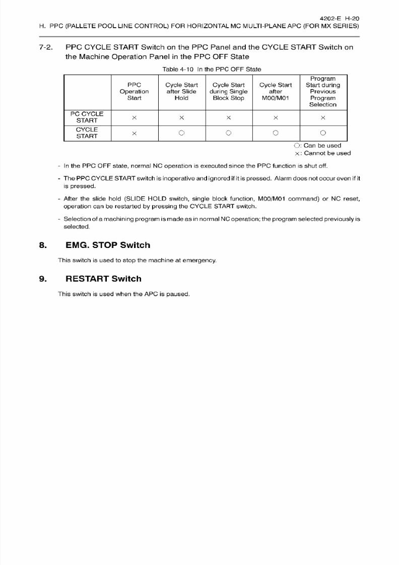
8/15/2019 Okuma Manuals 391
http://slidepdf.com/reader/full/okuma-manuals-391 235/397
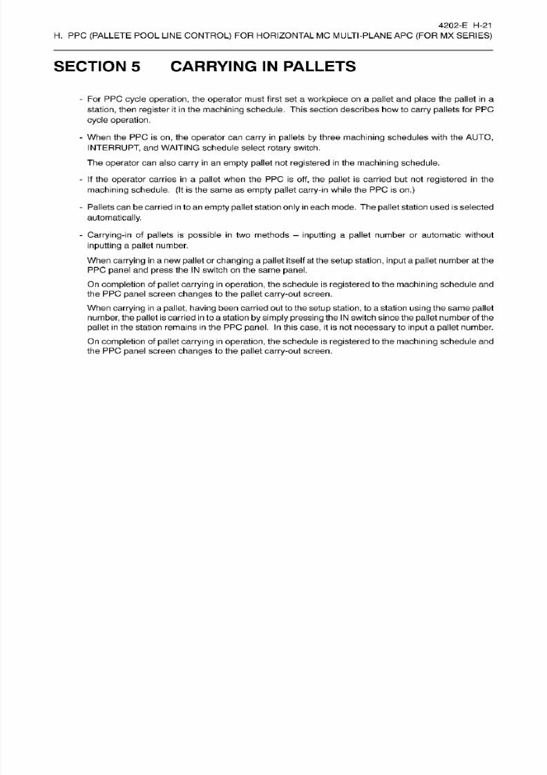
8/15/2019 Okuma Manuals 391
http://slidepdf.com/reader/full/okuma-manuals-391 236/397
4202-E
H-21
H.
PPC
(PALLETE
POOL
LINE
CONTROL)
FOR HORIZONTAL MC MULTI-PLANE AP C
(FOR
MX
SERIES)
SECTION 5 CARRYING
IN
PALLETS
-
Fo r
PP C cycle
operation,
the
operator
must
first
set a
workpiece
on a
pallet
and
place
the
pallet
in
a
station,
then
register
it in the
machining
schedule.
This
section
describes how to
carry pallets
for PPC
cycle operation.
-
When
the
PPC is
on,
the
operator
can
carry in pallets
by
three
machining
schedules
with
the
AUTO,
INTERRUPT,
and
WAITING schedule select
rotary
switch.
The operator
can also
carry in an
empty
pallet not registered in the machining schedule.
-
If
the operator
carries in
a
pallet
when
the PPC
is
off, the
pallet is
carried
but
not
registered in
the
machining schedule.
(It
is
the
same as
empty pallet carry-in
while the
PP C
is
on.)
-
Pallets
can
be carried
in
to
an
empty pallet
station
only in
each mode. The
pallet
station
used
is selected
automatically.
-
Carrying-in
of
pallets
is
possible
in
two
methods
-
inputting
a
pallet number
or
automatic
without
inputting
a pallet number.
When
carrying in
a
new
pallet or
changing
a pallet itself at the
setup
station,
input
a pallet number at the
PPC panel
and
press
the
IN
switch
on
the
same
panel.
On completion of pallet
carrying in
operation, the schedule is
registered
to the
machining
schedule and
the
PPC
panel
screen
changes
to
the
pallet
carry-out
screen.
When
carrying in
a
pallet, having
been carriedout
to
the
setup
station,
to
a
station
using
the
same
pallet
number, the
pallet
is
carried in to
a station
by simply
pressing the IN
switch since
the
pallet
number of
the
pallet
in
the station
remains
in
the PPC
panel.
In
this
case,
it
is
not
necessary
to
input a
pallet
number.
On
completion
of
pallet carrying in operation,
the
schedule is
registered
to
the
machining
schedule
and
the PPC
panel
screen
changes
to
the
pallet carry-out
screen.
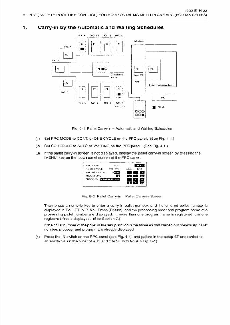
8/15/2019 Okuma Manuals 391
http://slidepdf.com/reader/full/okuma-manuals-391 237/397
4202-E
H-22
H.
PPC
(PALLETE
POOL
LINE
CONTROL)
FOR HORIZONTAL MC MULTI-PLANE AP C
(FOR
MX
SERIES)
1. Carry-in by the Automatic and
Waiting
Schedules
NO
9
NO . 10
NO .
II
NO. 12
Machine
PL
PL
L PL
NO.
R
-
IcJ.
IB
NO .
7
B B B
L
BIN
Circulation
jUalion
Wa n ST
B
NO
I
Inside
main
machine
PL
L
PL
Pl.
NO .
6
i
NC
NO.
5 NO .
4
NO. 3 NO.
2
Setup
ST
B
Work
Fig.
5-1
Pallet
Carry-in
-
Automatic
an d
Waiting
Schedules
(1) Set PPC
MODE to
CONT.
or ONE
CYCLE on
the
PPC
panel.
(See Fig.
4-1
.)
(2) Set
SCHEDULE
to
AUTO
or
WAITING on
the PP C
panel.
(See
Fig.
4-1.)
(3) If
the
pallet
carry-in
screen
is not
displayed, display
the
pallet
carry-in
screen
by
pressing the
[MENU]
key on
the touch panel screen of the PPC panel.
T
PALLET IN
AUTO CYCLE PT1 ?r:
PALLET IN P.
No
PROCESSING
PROGRAM
F7J2J
BB5M
0CO
ERR
LM
prrrn
DBD
nan
non
19
m
ITW
Fig.
5-2
Pallet Carry-in
Pallet Carry-in Screen
Then
press a
numeric
key
to enter a
carry-in
pallet number,
and
the
entered
pallet
number is
displayed in
PALLET
IN P.
No.
Press
[Return],
and
the
processing
order
and
program name
of a
processing pallet
number are displayed.
If
more
than
one program name
is registered,
the one
registered first is
displayed.
(See Section 7.)
If
the
pallet
number
of
the
pallet
in the
setup
station is
the
same
as that carried
ou t
previously, pallet
number,
process,
and program
are
already displayed.
(4)
Press the IN switch
on the
PPC panel (see
Fig.
4-1), and
pallets
in the
setup
ST are carr ied
to
an
empty ST
(in
the order of
a,
b,
and
c
to ST
with
No.9 in Fig.
5-1).

8/15/2019 Okuma Manuals 391
http://slidepdf.com/reader/full/okuma-manuals-391 238/397
4202-E H-23
H.
PPC
(PALLETE
POOL
LINE
CONTROL)
FOR HORIZONTAL MC MULTI-PLANE AP C
(FOR
MX
SERIES)
(5) When pallets are carried
in in
AUTO mode,
pallets are scheduled at the last of the automatic
schedule
(schedule
attribute
1) ;
and
when
in
WAITING
mode,
they are scheduled
at
the
last of
the
waiting
schedule
(schedule
attribute
0). (See
Section
8. )
(6)
After
carrying
in
of a
pallet,
the PPC
panel
screen
automatically
changes to the
pallet
carry-out
screen.
OOCO
IPHTW
«ÿ
PT1
PT2
ALM ERR
PALLET
IN
ALTO
CYCI.F.
PALLET
IN
P No
PROCESSING
PROGRAM
nTT*
PALLET
OUT
IRPT
CYCLE
_
PALLET
OU T
P.
No.
PHTH
1
P1000
3
P:IOOO
5 PSOOO
COO 3
ERR
TI
PT : ALM
pflTFI
DB
B
E
2 P2000
4
P4000
6 P6000
DOB
B E9
m
OP
IB
KB
Effl
Fig.
5-3 Screen Transfer
from
Pallet Carry-in Screen to Pallet Carry-out Screen

8/15/2019 Okuma Manuals 391
http://slidepdf.com/reader/full/okuma-manuals-391 239/397
4202-E
H-24
H.
PPC
(PALLETE
POOL
LINE
CONTROL)
FOR HORIZONTAL MC MULTI-PLANE AP C
(FOR
MX
SERIES)
2.
Carry-in by the
Interrupt
Schedule
NO.
9
NO.
10
NO. II
NO.
12
Machine
PLL
PL
L
NO .
8
Mr
0
NO.
7
0
0
PLB
[ci
LB(b|
Circulation
station
Watt
ST
0
NO.
I
Inside
main
machine
PL
PL
PL
L
NO .
6
5:1
NC
NO.
5
NO-
4
NO . 3 NO
2
Setup ST
:
Work
Fig.
5-4
Pallet
Carry-in
-
Interrupt
Schedule
(1) Set PPC
MODE to
CONT.
or ONE
CYCLE on
the
PPC
panel.
(See Fig.
4-1
.)
(2) Set
SCHEDULE
to
IRPT.
(See
Fig.
4-1.)
(3) If
the
pallet
carry-in
screen
is not displayed,
display
the pallet carry-in
screen
by
pressing the
[MENU]
key on
the touch panel screen of the PPC panel.
I'Al.LLT
IN
HUT
CYCLE
PALLET IN P.
No.
PROCESSING
PR
OGHAM
F3OT
0000
PT1
PT 2 ERR
LM
WW
WM Kl
D
Dun
KH
n
m
Fig.
5-5
Pallet
Carry-in
Pallet
Carry-in
Screen
Then
press
a
numeric
key
to enter a
carry-in
pallet
number, and the
entered
pallet
number is
displayed
in
PALLET
IN
P.
No. Press
[Return],
an d
the
processing
order
an d
program
name
of
a
processing
pallet
number are
displayed.
If more than one
program name
is
registered,
the one
registered
first is
displayed. (See
Section
7.)
If the
pallet
number
of
the
pallet in
the
setup
station
is
the same as that carried
out
previously,
pallet
number,
process,
and
program
are
already displayed.
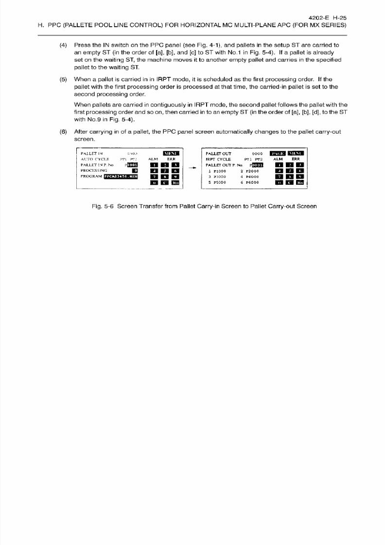
8/15/2019 Okuma Manuals 391
http://slidepdf.com/reader/full/okuma-manuals-391 240/397
4202-E H-25
H.
PPC
(PALLETE
POOL
LINE
CONTROL)
FOR HORIZONTAL MC MULTI-PLANE AP C
(FOR
MX
SERIES)
Press the
IN
switch on
the
PPC panel (see
Fig.
4-1), and pallets
in
the
setup
ST are carried to
an empty
ST
(in
the
order
of [a], [b],
and [c ]
to ST with
No.1 in
Fig. 5-4).
If
a
pallet
is
already
set
on
the
waiting ST,
the machine
moves it
to another
empty pallet
and
carries
in
the
specified
pallet
to
the waiting
ST.
When a
pallet
is
carried in in
IRPT mode,
it is
scheduled
as
the
first
processing
order.
If
the
pallet
with the
first
processing
order is processed
at
that
time,
the
carried-in pallet
is
set
to the
second
processing
order.
When
pallets
are
carried
in contiguously in IRPT
mode, the
second
pallet
follows the
pallet
with
the
first
processing
order and
so on,
then carried
in
to an
empty
ST
(in
the order of [a], [b],
[d],
to the ST
with
No.9
in
Fig. 5-4).
After
carrying in
of
a
pallet, the
PPC
panel
screen
automatically changes
to the
pallet carry-out
screen.
(4)
(5)
(6)
ooco
rami
BTCT
PTl
PT2
ALM
ERR
PALLET
JN
AUTO
CYCLE
PALLETOUT
IRPT CYCLE
_
PALLET OUT P.No.
pffiETl
2 P2000
4 P4QOO
6 P6000
(iOOO
ER R
TL PT: ALM
nnn
n
B
D
m
Kina
n
EB DO
PALLET
IN
P
No
PROCESSING
PROGRAM
HOT
1 P1000
3
P3000
5 PS
000
D
DD
IB
B
Efl
Fig.
5-6 Screen Transfer
from
Pallet Carry-in Screen
to Pallet
Carry-out Screen

8/15/2019 Okuma Manuals 391
http://slidepdf.com/reader/full/okuma-manuals-391 241/397
4202-E H-26
H.
PPC
(PALLETE
POOL
LINE
CONTROL)
FOR HORIZONTAL MC MULTI-PLANE AP C
(FOR
MX
SERIES)
2-1.
Machining
Schedule
in
the Interrupt
Schedule
Mode
on
PPC
Panel
Fo r the
pallet
carried in
in
the
interrupt
mode,
scheduling
method differs
depending
on the
setting
for
optional parameter
(bit) No.
63, bi t
1 .
If
pallets are carried
in, in
the
order
of
pallet
Nos.
6, 7,8,
and
9 while the
setting
for
the bit above
is
“OFF”,
the schedule
of
these pallets is
registered as
No.
1
,
2,
3,
and
4
as shown
in
Fig.
5-7.
After
carrying in pallets
in the interrupt
mode,
return theschedule mode
on
the PPC
panel
to automatic.
If
the mode is
changed
back
to
interrupt
and pallets
are carried
in
again
in
the
interrupt mode,
carrying
in
of
pallet
in the
interrupt
mode
is
possible
for the
pallets
having been carr ied in in
the
interrupt
mode
previously.
If
the PPC
cycle
operation
is executed
with
the
mode
set in the
interrupt mode, machining is
not executed
for the
pallets
carried
in
in
the interrupt
mode. To
execute machining for these
pallets,
return
the
mode to
automatic.
PARAMETER SET
*
MACHINING
SCHEDULE
OF
PALLET
*
SCHEDULE
ATT
0:
WAIT
/
I;
AUTO
PAGE
I
MAC. -SCH. PN O
No. 1
No.
2
No.
3
P0006
P0007
P0008
1
1
1
No .
4
P0009
1
No .
5
No. 6
No.
7
No .
8
No. 9
No .
10
P0001
P0002
P0003
P****
P****
1
1
1
0
0
P:
0
X
Y
Z
ACT POSIT
(WORK)
-551.552 100.000
100.000
A-Mtd
=MV_7[RETURN)
SC H
ITEM
T
ITEM
4-
[EXTENDI
EL SEARCH
OVE ADD
CHC
i
gj i (TT)rrT)rFÿ(TTi(TÿrF~T)rF~Bi
Fig. 5-7
Machining
Schedule of Pallet Screen
1

8/15/2019 Okuma Manuals 391
http://slidepdf.com/reader/full/okuma-manuals-391 242/397
4202-E
H-27
H.
PPC
(PALLETE
POOL
LINE
CONTROL)
FOR HORIZONTAL MC MULTI-PLANE AP C
(FOR
MX
SERIES)
If
pallets are carried
in, in
the order of palletNos.
6,
7,
8, and
9 while the
setting for
the bit above is
“ON”,
the
schedule
of these
pallets
is
registered
as
No.
4,
3,
2,
and 1 as shown
in Fig.
5-8.
Differing
from
the state of bit OFF,
machining
can
be continuously executed
even
if
the
mode selection at
the PP C
panel
is
interrupt.
PARAMETER
SET
*
MACHINING
SCHEDULE
OF PALLET
*
SCHEDULE
ATT
0: WAIT
/ I:
AUTO
PACE
I
MAC.
-SCH.
PNO.
No.
1
No. 2
No. 3
P0009
P0008
P0007
1
1
1
No.
4
P0006
1
No. 5
No. 6
No. 7
No.
8
No. 9
No.
10
P0001
P0002
P0003
P****
1
1
1
0
0
0
z
Y
AC T
POSIT
(WORK)
-551 .552 100 .000
100.000
A-Mtd
=MV_7[
RETURN]
SC H
ITEM
T
ITEM 4-
[EXTEND]
OV E
ADD DEL
SEARCH
CHG
nrTinrTirry)rFÿrTTinHnnÿiTiri
Fig.
5-8
Machining
Schedule of Pallet
Screen 2
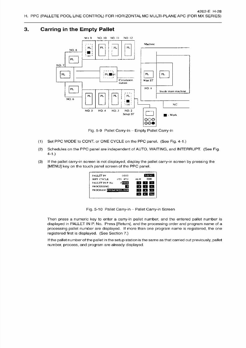
8/15/2019 Okuma Manuals 391
http://slidepdf.com/reader/full/okuma-manuals-391 243/397
4202-E H-28
H.
PPC
(PALLETE
POOL
LINE
CONTROL)
FOR HORIZONTAL MC MULTI-PLANE AP C
(FOR
MX
SERIES)
3. Carring in the
Empty
Pallet
NO.
9
NO .
10
NO .
II
NO.
12
Machine
i
PL
L PL
L
NO. 8
(c|
NO. 7
E3
0
L*|h
Circulation
station
Wail
ST
0
NO .
i
Inside main
machine
Q
PL
L PL
O.
6
Sll
NC
NO.
5 NO .
4
NO .
3 NO.
2
Setup
ST
:
Work
©O©
Fig.
5-9 Pallet Carry-in
Empty
Pallet Carry-in
(1)
Set PPC
MODE
to CONT. or ONE CYCLE on
the
PPC
panel.
(See
Fig. 4-1
.)
(2)
Schedules on the PP C
panel
are
independent
of
AUTO,
WAITING,
and INTERRUPT.
(See
Fig.
4-1.)
If
the
pallet
carry-in screen is
not
displayed,
display
the
pallet carry-in screen by
pressing
the
[MENU]
key
on the
touch panel screen
of the PPC
panel.
(3)
mmii
000
ITI
PT2
PALLITT
IN
IRPT
CYCLE
PALLET IN
P.
No
PROCESSING
PROGRAM
TT&?
ERR
LM
PETTH M l M l
Ml
E DBD
mm
ana
Q
nES
Fig.
5-10
Pallet
Carry-in
Pallet
Carry-in
Screen
Then
press
a
numeric
ke y
to enter a
carry-in
pallet
number,
and
the entered pallet
number is
displayed
in PALLET
IN
P. No.
Press [Return],
and
the
processing
order
and
program name of a
processing
pallet
number are
displayed. If
more
than
one program name
is registered,
the one
registered first
is
displayed.
(See
Section
7.)
If
the pallet number of the pallet in the
setup
station is the same
as
that carried out previously, pallet
number,
process, and
program
are
already
displayed.

8/15/2019 Okuma Manuals 391
http://slidepdf.com/reader/full/okuma-manuals-391 244/397
4202-E H-29
H.
PPC
(PALLETE
POOL
LINE
CONTROL)
FOR HORIZONTAL MC MULTI-PLANE AP C
(FOR
MX
SERIES)
(4)
Press the
EMPTY PALLET
switch
on
the PP C panel (see
Fig.
4-1),
and
pallets
in the setup ST
are
carried to
an
empty
ST
(in
the
order
of [a],
[b],
and [c] to
ST with
No.9
in Fig. 5-9).
(5)
Pallets are not
registered
to schedules.
(6)
After carrying in
of
a
pallet, the PP C panel
screen automatically changes
to
the
pallet
carry-out
screen.
PALLET
IN
ALTO CYCLE
PALLET
IN
P
No
PROCESSING
PROGRAM
HCT
cooc
?T l
PT:1
PALLET OU T
IRPT
CYCLE
PALLET OUT
P.
No.
p
wfal
1 P1000
3
P3000
5
P5000
0000
ER R
LM
ERR
ALM
T1
PT2
DDD
DBD
2 P2000
4
P4000
6 P6000
BBD
O
KB
U35
DDD
n KB
CO
Fig. 5-11
Screen Transfer from
Pallet
Carry-in
Screen
to Pallet
Carry-out
Screen

8/15/2019 Okuma Manuals 391
http://slidepdf.com/reader/full/okuma-manuals-391 245/397
4202-E H-30
H.
PPC
(PALLETE
POOL
LINE
CONTROL)
FOR HORIZONTAL MC MULTI-PLANE AP C
(FOR
MX
SERIES)
4.
Carry-in While the
PPC is Off
NO .
9
NO .
10
NO.
II
NO .
12
Machine
PL
PL
L PL
NO .
8
-Id-
El
NO .
7
0 0
:
PLBjbi
Ctrculalion
station
wait
ST
0
NO .
1
Inside
main machine
II? PL
PL;
L
NO .
6
t»
~[
NC
NO. 5 NO.
4
NO. 3
NO.
2
Setup
ST
:
Work
DO©
©©•
Fig.
5-12 Pallet Carry-in
Carry-in while the PPC is Off
(1)
Set PPC M ODE to OFF on the PP C
panel.
(See
Fig.
4-1.)
(2)
Schedules
on
the PP C
panel are independent of AUTO, WAITING,
AN D
INTERRUPT.
(See
Fig.
4-1.)
(3) If
the
pallet
carry-in screen
is not
displayed, display
the
pallet
carry-in
screen
by pressing
the
[MENU]
key on
the touch panel screen of the PPC
panel.
PALLET
IN
IKPT CYCLE
PALLET IN P No.
PROCESSING
PROGRAM
0000
FT1 PT2
ERR
LM
non
HDD
M l IB
IBB
Fig. 5-13 Pallet Carry-in
Pallet Carry-in Screen
Then
press
a
numeric
ke y
to enter a
carry-in
pallet
number,
and the ente red
pallet
number is
displayed
in PALLET IN P.
N o. P ress
[Return],
While the PP C is
off,
the processing
order
an d
program name of a
processing
pallet
number are not
displayed.
(PROCESSING
is
0 an d
no
PROGRAM
is
displayed.)
If
the
pallet number
of
the
pallet
in
the
setup
station is the
same
as
that carried out
previously,
pallet
number,
process,
and
program
are
already displayed.

8/15/2019 Okuma Manuals 391
http://slidepdf.com/reader/full/okuma-manuals-391 246/397
4202-E H-31
H.
PPC
(PALLETE
POOL
LINE
CONTROL)
FOR HORIZONTAL MC MULTI-PLANE AP C
(FOR
MX
SERIES)
(4)
Press the
IN
switch on
the
PPC panel (see
Fig.
4-1), and pallets
in
the
setup
ST are carried to
an empty
ST
(in
the
order
of [a], [b], and
[c ]
to ST with
No.
9
in
Fig.
5-12).
(5)
Pallets are not
registered
to schedules.
(6)
After carrying in
of
a
pallet, the PP C panel
screen automatically changes
to
the
pallet
carry-out
screen.
itTHTW
«nw
ALLET
IN
ALTO CYCLE
PALLET
IN
P
No
PROCESSING
PROGRAM
HCT
cooc
?T l
PT:1
PALLET OU T
IRPT
CYCLE
PALLET OUT
P.
No.
p
wfal
1 P1000
3
P3000
5 PS
000
0000
ER R
LM
ERR
ALM
T1
PT2
DDD
DBD
2 P2000
4
P4000
6 P6000
BBD
O
KB
U35
DDD
n KB
CO
Fig.
5-14
Screen
Transfer
from
Pallet
Carry-in
Screen
to Pallet Carry-out Screen
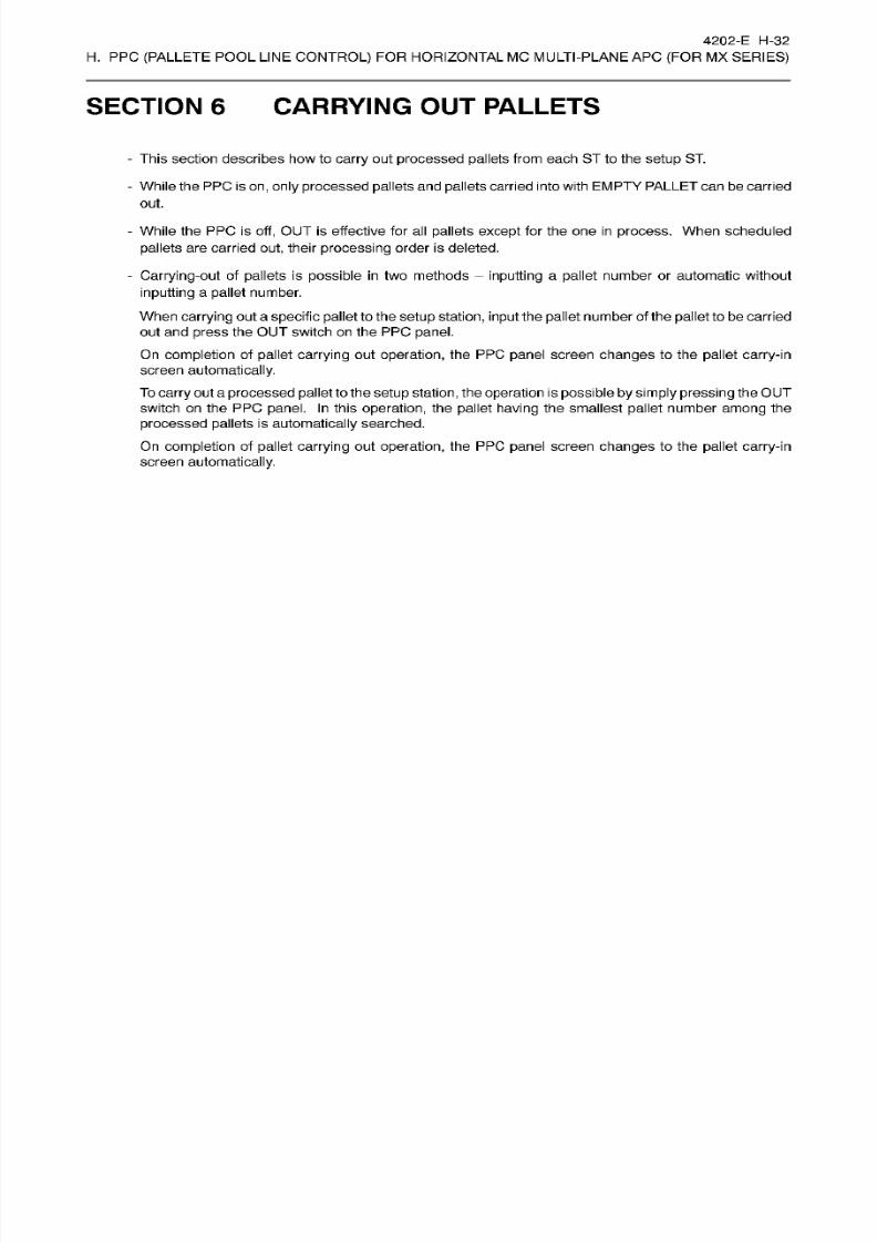
8/15/2019 Okuma Manuals 391
http://slidepdf.com/reader/full/okuma-manuals-391 247/397
4202-E H-32
H.
PPC
(PALLETE
POOL
LINE
CONTROL)
FOR HORIZONTAL MC MULTI-PLANE AP C
(FOR
MX
SERIES)
SECTION 6 CARRYING
OUT
PALLETS
-
This
section describes
how
to
carry
out
processed pallets
from
each
ST
to
the
setup
ST.
-
While the PPC is
on ,
only
processed pallets and pallets carried into with
EMPTY
PALLET
can
be
carried
out.
-
While the PPC is
off,
OUT
is effective for
all
pallets
except for
the on e
in
process.
When scheduled
pallets
are carried
out,
their
processing
order
is
deleted.
-
Carrying-out
of
pallets is
possible in
two methods
inputting
a pallet number or automatic without
inputting
a
pallet
number.
When carrying
out a
specific pallet
to the
setup
station, input
the
pallet
number of the
pallet
to
be
carried
out an d press
the OUT switch on
the
PP C
panel.
On
completion
of
pallet
carrying
out
operation,
the PPC
panel
screen changes
to the
pallet
carry-in
screen
automatically.
To
carry
out a
processed pallet
to the
setup
station,
the
operation
is
possible
by simply pressing
theOUT
switch
on
the PPC panel.
In
this
operation,
the
pallet
having
the
smallest
pallet
number
among
the
processed
pallets
is
automatically
searched.
On completion
of pallet
carrying
out operation,
the
PP C
panel screen changes
to
the
pallet
carry-in
screen automatically.
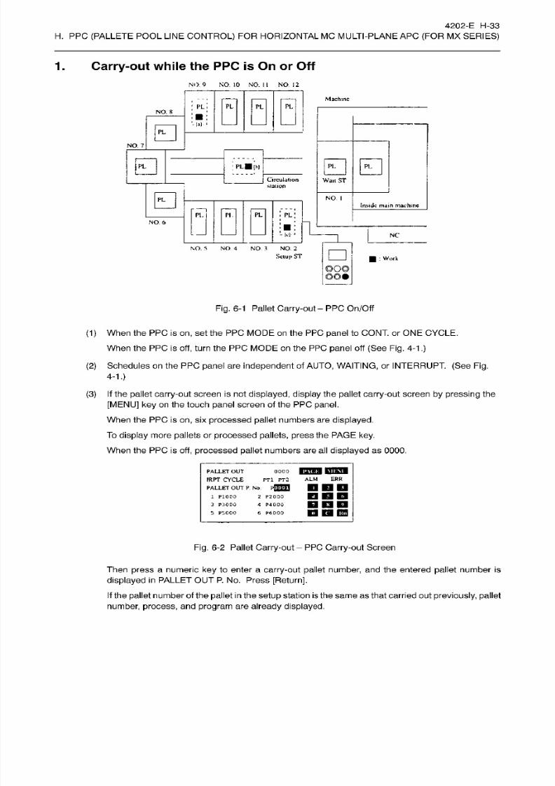
8/15/2019 Okuma Manuals 391
http://slidepdf.com/reader/full/okuma-manuals-391 248/397
4202-E H-33
H.
PPC
(PALLETE
POOL
LINE
CONTROL)
FOR HORIZONTAL MC MULTI-PLANE AP C
(FOR
MX
SERIES)
1
. Carry-out
while
the PPC
is
On
or
Off
NO .
9
NO 10
NO.
II
NO .
12
Machine
PL
PL
L
PL
NO . 8
[ • > -
0
NO.
7
0
0 0
LBib)
Circulation
station
Wan
ST
0
NO
I
Inside
main
machine
PL
I. PI PL
NO .
6
-
[<l
NC
NO
5
NO
4
NO 3 NO .
2
Setup
ST
:
Work
©o©
Fig.
6-1
Pallet
Carry-out
-
PP C
On/Off
(1)
When
the
PPC
is
on , set
the PPC
MODE on
the
PPC
panel
to CONT.
or ONE
CYCLE.
When
the
PPC
is off,
turn
the PPC MODE
on the
PP C
panel
off (See
Fig.
4-1
.)
(2)
Schedules
on
the
PP C
panel
are
independent
of
AUTO, WAITING,
or INTERRUPT.
(See Fig.
4-1.)
(3) If
the
pallet
carry-out
screen is
not
displayed, display
the
pallet
carry-out
screen by pressing the
[MENU]
ke y
on
the touch
panel
screen of
the
PPC
panel.
When
the
PPC
is
on ,
six
processed
pallet
numbers are
displayed.
To
display
more
pallets
or
processed
pallets,
press
the PAGE
key.
When the
PPC
is
off,
processed pallet
numbers are al l
displayed as
0000.
0000
iPTini MIHB
PT l
PT2
ALM ERR
PALLET
OUT
fRPT
CYCLE
PALLET
OU T
P.
No .
F®fl
2 P2000
4
P4000
6
P6000
1
P1000
3
P:JOOO
5
P5000
DDD
IQ
IBH
Fig.
6-2 Pallet Carry-out PP C Carry-out Screen
Then
press
a numeric
key
to
enter
a
carry-out
pallet
number,
and the
entered
pallet
number
is
displayed in PALLET
OUT
P. N o. P re ss
[Return],
If
the
pallet number of the
pallet
in
the setup
station
is
the same
as
that
carried out previously, pallet
number,
process,
and
program
are
already
displayed.
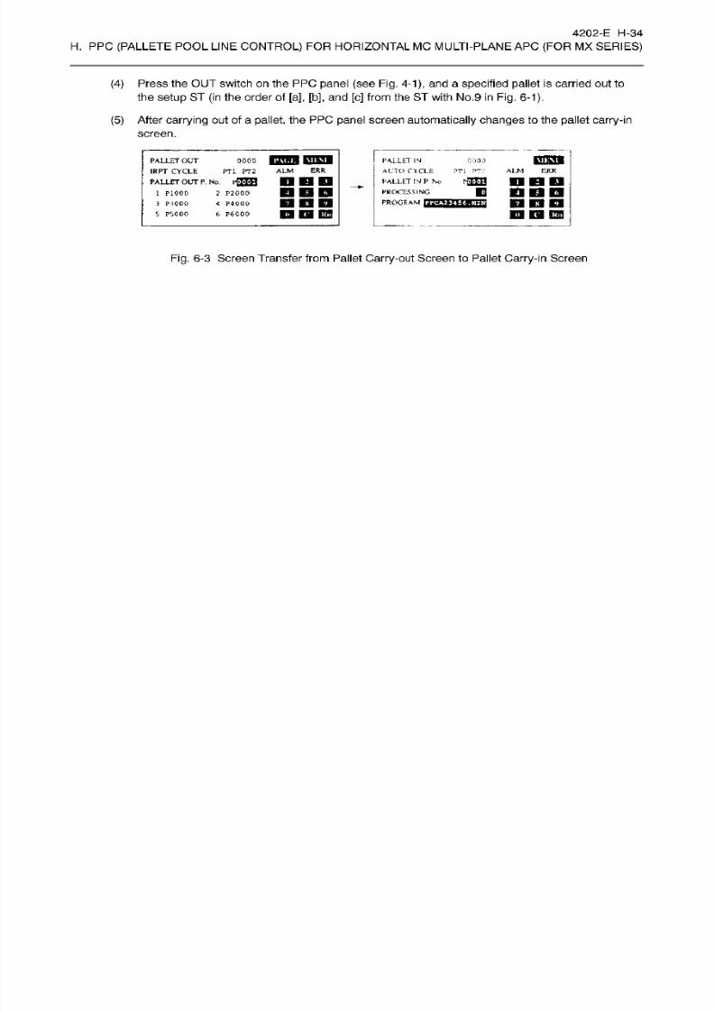
8/15/2019 Okuma Manuals 391
http://slidepdf.com/reader/full/okuma-manuals-391 249/397
4202-E H-34
H. PP C
(PALLETE
POOL
LINE
CONTROL)
FOR HORIZONTAL MC
MULTI
-PLAN
EAPC
(FOR
MX
SERIES)
(4)
Press
the
OUT
switch
on the PP C
panel (see
Fig.
4-1),
and
a
specified
pallet
is
carried
out to
the
setup
ST (in the order
of
[a], [b],
and
[c]
from the ST with No.
9
in Fig. 6-1).
(5)
After
carrying
out of a
pallet,
the PPC
panel
screen
automatically changes
to the
pallet carry-in
screen.
IBTOI
ALLET OU T
IRPT CYCLE
PALLET
OUT
P. No.
2 P2000
4
P4000
6 P6000
PALLET
IN
AUTO
CYCLE
PT1 PT::
PALLET IN
P
No
PROCESSING
PROGRAM
cooo000
ERR
LM
ALM
ERR
T1 PT2
P0EJ
DBD
DDD
PiOOO
3
PilOOO
5
PSOOO
BOD
nm
non
Dm
BO
Fig.
6-3
Screen Transfer
from
Pallet Carry-out Screen to Pallet Carry-in Screen
8/15/2019 Okuma Manuals 391
http://slidepdf.com/reader/full/okuma-manuals-391 250/397
4202-E H-35
H.
PPC
(PALLETE
POOL
LINE
CONTROL)
FOR HORIZONTAL MC MULTI-PLANE AP C
(FOR
MX
SERIES)
2.
Automatic Carrying-out of Processed Pallet when Only
Two
Pallets
Are Used
When the
system
uses three or more
pallets,
the
pallet
placed in
the
waiting
station
is
automatically
carried
ou t to
the
setup
station since the
operation
to
change the
pallet
with the
on e
in
other stations
is
necessary.
However,
if
only
two
pallets
are
used, there
are
no
operations
to
change the
pallet
in
the waiting
station
with
the pallet in
other
station,
requiring
an
operator
to execute
pallet
carry-out
operation
each
time the
pallet
in
the
waiting station is
carried
ou t to
the setup
station.
To
facilitate the system operation
when
only
two
pallets
are used,
set
“ON” for
optional parameter (bit)
No.
63,
bit 0, which makes the
function
to
automatically
carry ou t
the
processed pallet to
the
setup
station
effective.
-
The
setting
for
optional parameter
(bit)
No .
63,
bit
0
determines whether
or
not this
specification
is
effective
(effective: 1,
ineffective:
0).
Default is “0”
(ineffective).
-
Operation
conditions:
Not
during
pallet
carrying-in
or
carrying-out
operation.
PPC
operation
error
not
displayed.
There
are
no second
and
later
machining
schedule.
There is no
pallet in
the
setup
station.
There is a
processed
pallet
in the
waiting
station.
The machine is not a
pallet
operation
disabled
state.
The
pallet
in
the
waiting
station is
automatically
carried out when
all
of the conditions above are satisfied.
Automatic
pallet
carrying-out
operation
from the
waiting
station is
completed
when the
pallet
is carried
out
to the
setup
station;
the
pallet carry-out
command
output
to the machine is turned off.
-
If there is
a
pallet
in
the
setup station,
the
system
operation stops
even after
the
completion
of
machining
in
the machine and automatic
carrying
ou t from
the
waiting
station
is not executed.
-
If the
next
machining
schedule
already
exists when
the machining starts in the
machine,
no
special
processing is
executed
since
the specification is “the
pallet
in
the
waiting stationis automatically
carried
out
hen the next pallet command
is
output”.
- The last processed
pallet
remains in
the machine
and is not
carried
out
automatically.
In
this
case,
the
operator
should carry
in
a
dummy
pallet into the
waiting
station, executes
M160,
then carries
out
the
pallet.
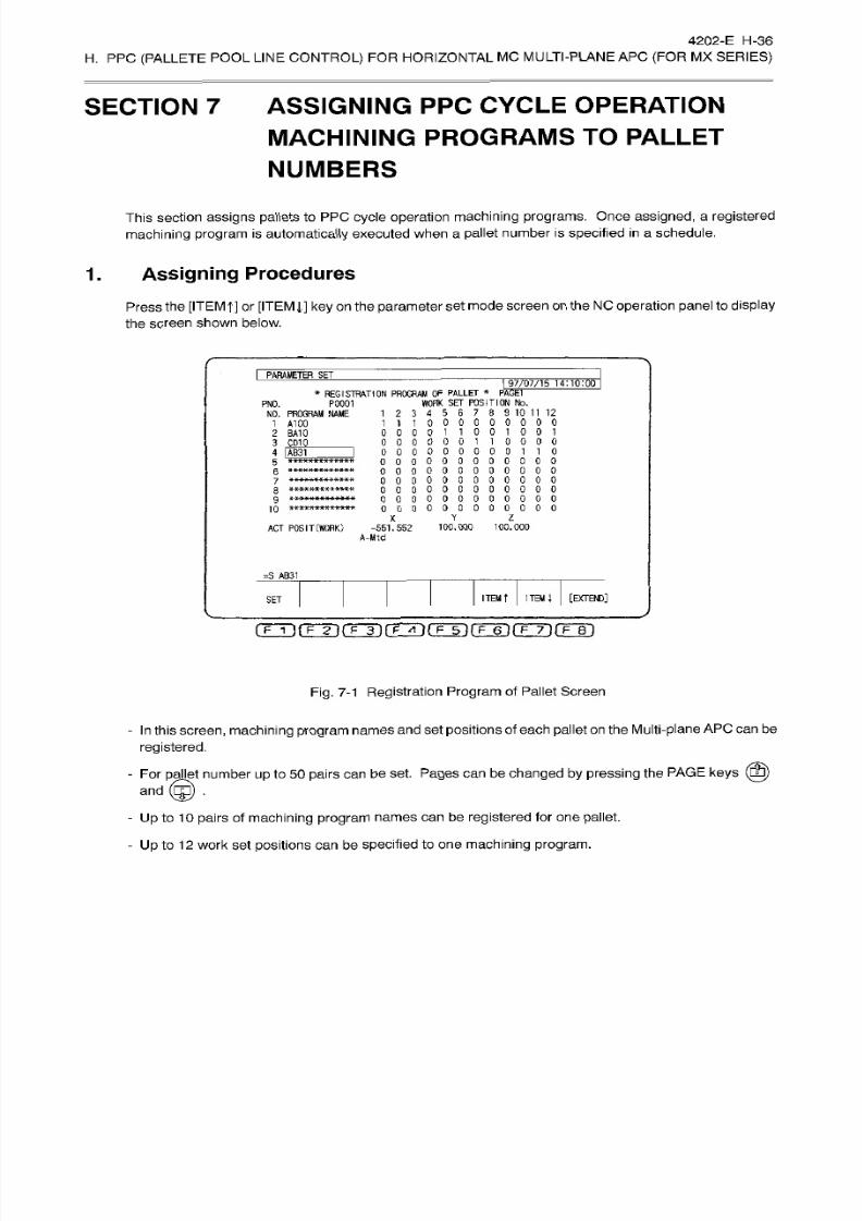
8/15/2019 Okuma Manuals 391
http://slidepdf.com/reader/full/okuma-manuals-391 251/397
4202-E
H-36
H.
PP C (PALLETE
POOL
LINE
CONTROL)
FO R
HORIZONTAL
MC
MULTI-PLANE
APC
(FOR
MX
SERIES)
SECTION
7 ASSIGNING
PPC CYCLE
OPERATION
MACHINING
PROGRAMS
TO
PALLET
NUMBERS
This section assigns pallets
to
PPC
cycle operation
machining
programs.
Once
assigned,
a
registered
machining
program
is
automatically
executed
when a
pallet number is
specified
in
a
schedule.
1.
Assigning
Procedures
Press the
[ITEM
t]
or
[ITEM
J,] key
on the
parameter set
mode
screen on the
NO operation
panel to
display
the screen
shown below.
I
PARAMETER~SET
97/07/15
14:10:00
*
REGISTRATION
PROGRAM OF
PALLET
*
PAGE
WORK SE T POSITION No.
1
2
3
4
5 6
7 8
9
10 11 12
111000000000
000011001001
0000001
10000
000000000110
00000000
0 0 0 0
0 0
000000000
000000000
000000000000
000000000000
X Y
Z
AC T POSIT
(WORK)
-551.552
100.000 100.000
A-Mtd
PS 071
NO.
NO.
PROGRAM
NAME
1 A100
2 BA10
3
CD12
4
IAB31
0 0 0 0
0 0 0
0
0
0 0
0
0 0
5
0
0
HXXXXMXKX
H*
7
»-X K X*'X
X -X X9BBE*
ÿ**ÿ *»*****ÿ**
10
=S AB31
ITEM
ITEM
i
[EXTEM)]
ET
nÿrrrirÿnÿnÿrrÿ
prying
Fig. 7-1
Registration
Program
of
Pallet
Screen
-
In
this
screen,
machining program
names
and
set
positions
of each
pallet on
the
Multi-plane AP C
can be
registered.
- For
pallet
number
up
to
50
pairs
can
be
set.
Pages ca n be
changed
by
pressing
the
PAGE
keys
(0)
©
nd
- Up to
10
pairs
of
machining
program names
can be
registered
for
one pallet .
-
Up
to
12
work
se t
positions can
be specified to
one
machining program.
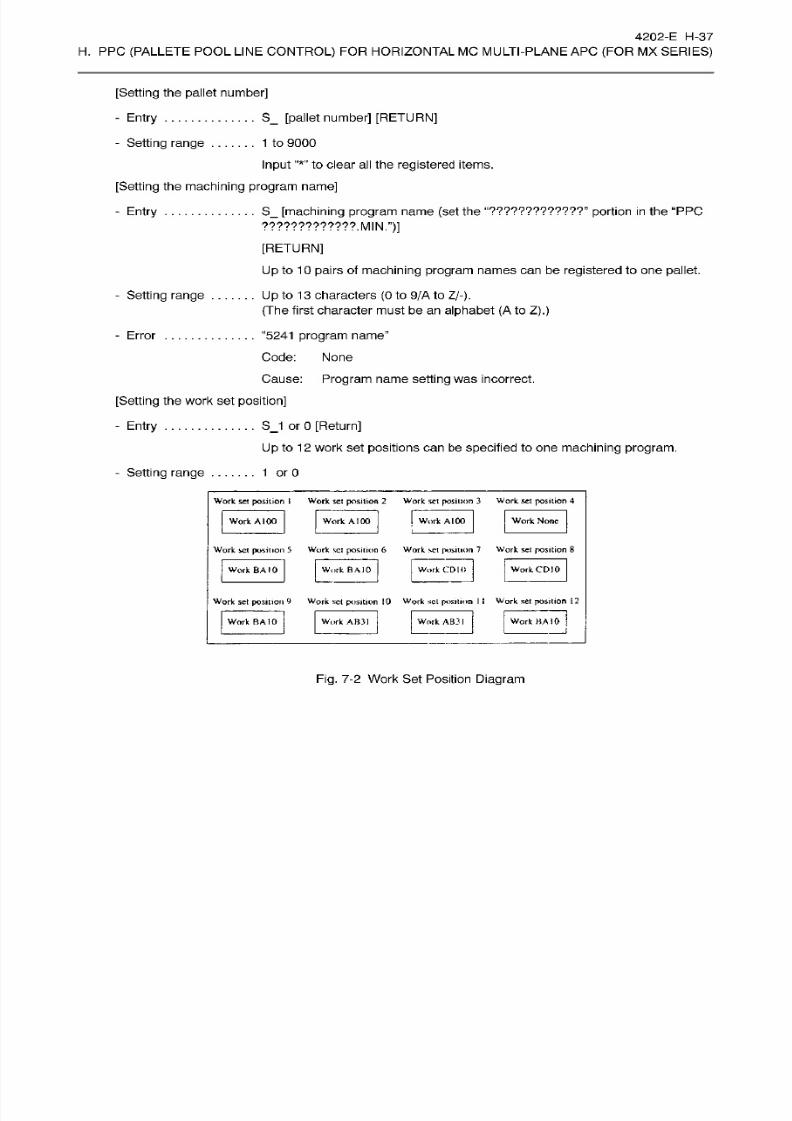
8/15/2019 Okuma Manuals 391
http://slidepdf.com/reader/full/okuma-manuals-391 252/397
4202-E H-37
H.
PPC
(PALLETE
POOL
LINE
CONTROL)
FOR HORIZONTAL MC MULTI-PLANE AP C
(FOR
MX
SERIES)
[Setting
the pallet number]
-
Entry
-
Setting
range
S_
[pallet number] [RETURN]
1 to
9000
Input to clear
al l the
registered
items.
[Setting
the
machining program
name]
-
Entry
S_
[machining
program
name
(set
the
“?????????????”
portion
in
the
“PPC
?????????????.MIN.”)]
[RETURN]
Up
to 10
pairs
of
machining
program names can
be registered
to on e
pallet.
Up
to 13
characters
(0
to
9/A
to
Z/-).
(The
first character must
be an
alphabet (A
to
Z).)
-
Setting range
“5241
program
name’’
Code: None
Cause:
Program
name
setting
was
incorrect.
-
Error
[Setting the work set
position]
SJ
or 0
[Return]
Up
to
12 work
set
positions
can be
specified
to one
machining program.
-
Entry
-
Setting
range
1
orO
Work
set position I Work scl position
2
Work set
position
3
Work set
position
4
Work
A 1
00
Work
None
ork
AI00
Work
A
100
L
Work set position 5
Work
set position
6 Work
set
position
7 Work
scl
position 8
Work BAIO
|
Work CDJ0
ork
BA 10
Work CD10
Work
set
position
9
Work
set position 10
Work
scl
position 1 1
Work set
position
12
Work BA 10
ork
BA
10
Work AB31
Work AB 3
1
Fig. 7-2
Work
Set Position
Diagram

8/15/2019 Okuma Manuals 391
http://slidepdf.com/reader/full/okuma-manuals-391 253/397
4202-E H-38
H.
PPC
(PALLETE
POOL
LINE
CONTROL)
FOR HORIZONTAL MC MULTI-PLANE AP C
(FOR
MX
SERIES)
-
If one
machining
program
machines
one
pallet, set as shown below.
PARAMETER
SET
I
97/07/15
14:10:00
*
REGISTRATION
PROGRAM OF PALLET
*
PAGE1
WORK SET POSITION No .
1
2 3
4
5
6 7
8
9
10 11
12
1
00000000000
000000000000
0 0 0
0
0
0 0
0
0 0 0 0
0 0 0 0 0
0
0
0
0 0 0
0
oooooooooooo
000000000000
oooooooooooo
oooooooooooo
oooooooooooo
P0001
NO.
NO.
PROGRAM
NAME
1
A2356
2
3
0
0 0
0 0
0 0
0
0 0
4
5
6
7
*************
8
?
10
X Y
Z
AC T
POSIT
(WORK
-551.552
100.000
100.000
A-MId
=S
AB31
ITEM
l
[EXTEND]
TEM
t
ET
(TT>(TTirFTirÿr iÿ(T~r)(T'T)(TBi
Fig.
7-3 For One
Pallet,
One
Machining Program -
One
Machining
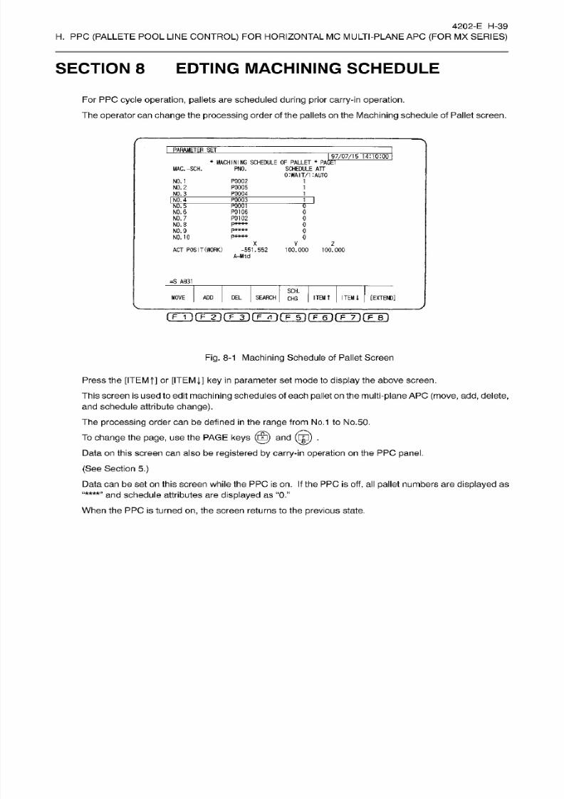
8/15/2019 Okuma Manuals 391
http://slidepdf.com/reader/full/okuma-manuals-391 254/397
4202-E H-39
H.
PPC
(PALLETE
POOL
LINE
CONTROL)
FOR HORIZONTAL MC MULTI-PLANE AP C
(FOR
MX
SERIES)
SECTION 8 EDTING MACHINING
SCHEDULE
Fo r PPC
cycle
operation, pallets
are
scheduled
during
prior
carry-in
operation.
The
operator
can change the
processing
order of
the
pallets
on
the
Machining
schedule of
Pallet screen.
PARAMETER
SE T
I
97/07/15
*
PAGET
14:10:00
*
MACHINING
SCHEDULE
OF
PALLET
SCHEDULE ATT
0:WAIT/1
:AUT0
MAC.-SCH.
PNO.
NO .
1
P0002
P0005
P0004
1
NO .
2
1
NO . 3
1
NO. 4 P00C3
M
NO . 5
NO .
6
TOOT
P0106
P0102
pit
K
M
K
0
0
NO . 7
0
NO .
8
0
NO . 9 0
NO. 10
0
X
V
z
AC T
POSIT(WORK)
-551.552
100.000
100.000
A-Mtd
=S
AB31
SCH.
ITEM
t
[EXTEND]
OVE
AD D
DEL
SEARCH
ITEM
l
HG
Fig.
8-1
Machining
Schedule of Pallet Screen
Press the [ITEMf]
or
[ITEM J,]
ke y in
parameter set mode to
display
the above screen.
This
screen is used to edit
machining
schedules of
each pallet
on
the multi-plane AP C
(move,
add, delete,
and schedule attribute
change).
The
processing
order can be
defined
in
the range from No.1 to
No.50.
To
change
the
page,
us e
the
PAGE
keys
(©)
and
(ÿ)
.
Data
on
this
screen can
also
be
registered by carry-in
operation
on
the PPC
panel.
(See
Section
5.)
Data
can
be set
on
this
screen
while the
PPC is on. If
the PPC
is
off, al l
pallet
numbers
are
displayed
as
and schedule attributes are
displayed
as
“0.”
When the PP C is
turned on,
the
screen
returns to the
previous state.
“****”
8/15/2019 Okuma Manuals 391
http://slidepdf.com/reader/full/okuma-manuals-391 255/397
4202-E H-40
H.
PPC
(PALLETE
POOL
LINE
CONTROL)
FOR HORIZONTAL MC MULTI-PLANE AP C
(FOR
MX
SERIES)
(1)
Moving Machining Schedules
- The
operator
can move the
processing
order of
machining
schedules.
-
Move the
cursor to
a
line
containing
the
pallet whose
machining
schedule
is
to be
moved,
press
the
[MOVE] function
key.
Enter a required
processing
order
and
press [RETURN], The pallet number
moves
to
the line selected
for
the
new processing
order.
The schedule attribute
also moves accordingly
and the tab le
is
updated.
Moving
procedures
. . .
MV_[processing
order]
[RETURN]
Moving range
1
to
maximum stat ion
number
If
the
pallet
with
processing
order
1
is
in
process
on the
machine,
it cannot
be
moved to
processing
order
1.
If
a pallet
sharply
exceeds the
present
processing
order even if it
does
not
exceeds the
maximum station number, it
is
added after
the
maximum processing
order
set
at
present
and
no
blank
processing orders
are
generated.
“5286
Set condition error
Code
:1
The pallet
at
the
source cursor position
is
not
ready
for
machining.
(The
pallet
number at the source
cursor
position is
not
found.)
:2
Th e
same
pallet number
is
specified
as
the
source and
destination.
Error
:3
Th e
destination
pallet
is not
ready
for
processing.
(The pallet
number
at
the
destination
cursor
position
is
not
found.)
(2)
Adding Machining
Schedules
-
Machining
schedules can be added.
-
Move
the
cursor
to
a
line to which
a
machining
schedule is
to
be added
and
press
the
[ADD]
function
key.
Enter
a new
pallet
number
and
press [RETURN],
The
entered
pallet
number is
added
using
the
schedule attribute of
the
source l ine and the table is
updated.
Adding
procedure
NSJpallet
number]
[RETURN]
Addition
range
1
to maximum station number
Machining
schedules
can
be added
for
only
pallets
registered in
the
pallet
station
number/pallet number table.

8/15/2019 Okuma Manuals 391
http://slidepdf.com/reader/full/okuma-manuals-391 256/397
4202-E
H-41
H.
PPC
(PALLETE
POOL
LINE
CONTROL)
FOR HORIZONTAL MC MULTI-PLANE AP C
(FOR
MX
SERIES)
“5286 Set
condition error”
Code
:
1 The
pallet
at the source cursor
position
is not
ready
for
machining.
(The pallet
number at the
source
cursor
position
is not
found.)
:2 The
pallet
number to be added
is
not found.
:3 The
operator
attempted
to
add
a
pallet
number
not
registered
in
the pallet station number/pallet number table.
:4
The
operator attempted to add a pallet number
whose
processing
number
is
already
set.
Error
(3) Searching for Machining
Schedules
-
The operator can search the
processing
order
of machining
schedules and move them
with
the
cursor.
-
Press
the [SEARCH] function and
enter a
processing
order to
be
searched.
The cursor
moves
to
the
line
containing
the entered
processing
order.
Search
procedure
order] [RETURN]
1
to maximum
processing
order
registered
“5286 Set
condition error”
Code
:1 The
pallet
at
the
source cursor position
is not ready
for
machining.
(The pallet
number at the source cursor position is not
found.)
Search
range
Error
(4) Deleting Machining
Schedules
-
Machining schedules
can
be deleted.
-
Move
the
cursor
to a line from which the
machining schedule
is to
be
deleted and
press
the
[DEL]
function.
The l ine selected with the cursor is
deleted
and
the
table
is
updated.
Delete
procedures
____
EL
[RETURN]
Delete
range 1
to maximum
processing
order
registered
If
the
pallet
with
processing
order
1
is
in process
on the
machine,
it
cannot be
deleted.
“5286
Set condition
error”
Code :1
The
pallet
at the source
cursor
position
is
not
ready
for
machining.
(The
pallet
number at
the source cursor
position
is
not
found.)
Error
8/15/2019 Okuma Manuals 391
http://slidepdf.com/reader/full/okuma-manuals-391 257/397
4202-E
H-42
H.
PPC
(PALLETE
POOL
LINE
CONTROL)
FOR HORIZONTAL MC MULTI-PLANE AP C
(FOR
MX
SERIES)
(5)
Changing
the Schedule Attribute
- The schedule attribute
can
be selected from wait or automatic. The default is wait operation “0.”
-
Move the
cursor to the
processing
order whose
schedule
attribute is to be
changed
and press
the
[SCH.
CHG]
function.
When the schedule attribute
is “0,”
it
changes
to
“1 ;
and when
“1,”
it
changes
to
“0.”
Change procedures
. .
SCH [RETURN]
Change range
Oor
1
Fo r the
pallet
to be machined
by
wait operation, enter “0.”
Fo r
the pallet to be
machined
by automatic operation,
enter
“1
Changing
SCHEDULE
ATT
from
“0”
(WAIT)
to “1”
(AUTO),
the
processing
order moves after the last
pallet
with
SCHEDULE ATT
of
“1”
(AUTO).
Changing
SCHEDULE
ATT
from
“1”
(AUTO)
to
“0”
(WAIT),
the
processing
order moves
after the
last
pallet
with
SCHEDULE
ATT
of
“0”
(WAIT).
“5286
Set
condition
error
Code :1 The
pallet
at the source
cursor
position
isnot
ready
for
machining.
(The
pallet
number at
the source cursor
position
is not
found.)
Error
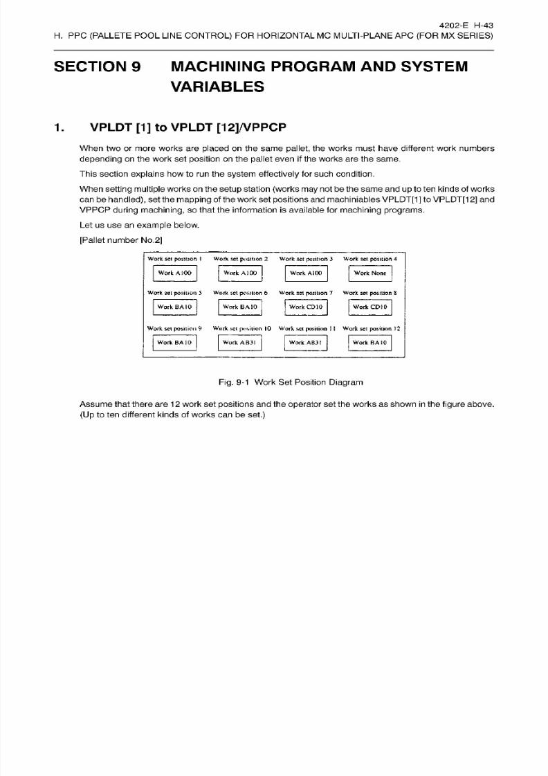
8/15/2019 Okuma Manuals 391
http://slidepdf.com/reader/full/okuma-manuals-391 258/397
4202-E H-43
H.
PPC
(PALLETE
POOL
LINE
CONTROL)
FOR HORIZONTAL MC MULTI-PLANE AP C
(FOR
MX
SERIES)
SECTION 9 MACHINING
PROGRAM AND
SYSTEM
VARIABLES
1
.
VPLDT [1
]
to
VPLDT [12]/VPPCP
When two or
more
works are
placed
on
the
same
pallet,
the works
must
have
different
work numbers
depending
on the work
set position
on
the pallet
even
if
the works are the same.
This section
explains
howto run
the
system
effectively
for such condit ion.
When
setting
multiple
works
on
the setup
station
(works
may
not be
the same
and
up
to tenkinds of
works
can
be
handled),
set
the
mapping
of the
work set
positions
an d
machiniables VPLDT[1]
to
VPLDT[1
2] and
VPPCP
during machining,
so that the
information
is
available
for
machining programs.
Le t us u se a n
example
below.
[Pallet
number
No .
2]
Work sc i
position
I
Work set
position
2
Work se t position
3
Work
set position
4
Work A 100 Work
A)
00
Work None
ork
A100
Work set position
5
Work set position
6
Work set position 7 Work set posit ion 8
Work
CD
10ork
BA
10
Work
BA
10 Work CD10
Work set position 9
Work
set
position 10
Work
set position
1
1
Work set
position
12
Work
AB31
ork BA
10 Work
AB31
Work BA
10
Fig.
9-1 W ork
Set Position
Diagram
Assumethat there are
12
work set
positions
and the
operator
set
the
works
as
shown
in
the
figure
above.
(U p
to ten
different
kinds
of works
can
be
set.)

8/15/2019 Okuma Manuals 391
http://slidepdf.com/reader/full/okuma-manuals-391 259/397
4202-E
H-44
H.
PPC
(PALLETE
POOL
LINE
CONTROL)
FOR HORIZONTAL MC MULTI-PLANE AP C
(FOR
MX
SERIES)
The
operator assigns
work set positions to
machining programs
for a pallet
in
advance.
PARAMETER
SE T
97/07/15
14:10:00
*
REGISTRATION PROGRAM
OF PALLET
*
PAGE1
WORK
SET
POSITION
No.
1
2
3
4
5
6
7
8 9 10
11
12
111000000000
000011001001
0000001
10000
0000000001
1 0
000000000000
0 0 0 0 0 0 0 0
0
0 0 0
000000000000
000000000000
0 0 0 0 0 0 0 0 0 0 0 0
000000000000
P0002
NO . PROGRAM
NAME
1
A100
2 BA10
3 CD10
_
,
4
[AB31
PNO.
5
6
8
9
10
X
Y
Z
ACT
POSIT(WORK)
-551.552
100.000
100.000
A-Mtd
=S AB31
[EXTEND]
TEM
ITEM
4
ET
(ÿ~T)
(~F~T1
fF~3l
fF~ÿ fFÿ
fF~6l
fF~7~)
fF~in
Fig.
9-2
Registration Program
of Pallet Screen
When
this
pallet
is carr ied into
the
machine,
the
NC
first selects a
program automatically,
then set
system
variables
as
shown
below.
VPLDT[1]=1
,
VPLDT[4]=0,
VPLDT[7]=0,
VPLDT[10]=0,
VPPCP=$007H
VPLDT[2]=1
,
VPLDT[5]=0,
VPLDT[8]=0,
VPLDT[11]=0,
VPLDT[3]=1
VPLDT[6]=0
VPLDT[9]=0
VPLDT[12]=0
The machining program
checks the value of
VPLDT[1]
to
VPLDT[12]
(1 orO) and
the NC machines
works
while
checking
whether a work with PPCA100.MIN is set
at
each work set position from
1
to
12.
The
machining
program
also
checks hexadecimal data of
VPPCP=$007H
and
the
NC
machines works
while
checking
whether a work with PPCA100.MIN is set
at
each work set position
from
1
to 12
in
the
same
way as VPLDT[1] to VPLDT[12].
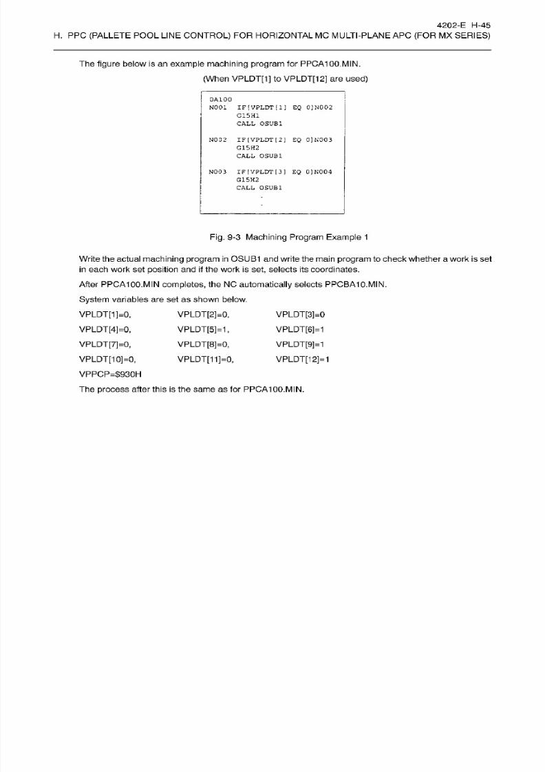
8/15/2019 Okuma Manuals 391
http://slidepdf.com/reader/full/okuma-manuals-391 260/397
4202-E H-45
H.
PPC
(PALLETE
POOL
LINE
CONTROL)
FOR HORIZONTAL MC MULTI-PLANE AP C
(FOR
MX
SERIES)
The figure below is
an
example
machining
program for
PPCA100.MIN.
(When VPLDT[1] to VPLDT[12] are used)
OAIOO
N001
IF
VPLDT
[
1
J
EQ
0]N002
G15H1
CALL OSUB1
N002 IF
[VPLDT [
2
]
EQ
0]K003
G15H2
CALL
OSUB1
N003
IF
[VPLDT
[3 ]
EQ
0]N004
G15H2
CALL OSUB1
Fig.
9-3
Machining Program
Example
1
Write
the
actual
machining
program
in
OSUB1 and write the main program to check whether
a
work
is set
in
each work set
position
and if the work
is set,
selects its coordinates.
After
PPCA100.MIN
completes,
the NO
automatically
selects
PPCBA10.MIN.
System
variables are
set
as shown
below.
VPLDT[2]=0,
VPLDT[5]=1,
VPLDT[8]=0,
VPLDT[11]=0,
VPLDT[1]=0,
VPLDT[4]=0,
VPLDT[7]=0,
VPLDT[10]=0,
VPPCP=$930H
The
process
after
this
is
the sam e as
for
PPCA100.MIN.
VPLDT[3]=0
VPLDT[6]=1
VPLDT[9]=1
VPLDT[12]=1
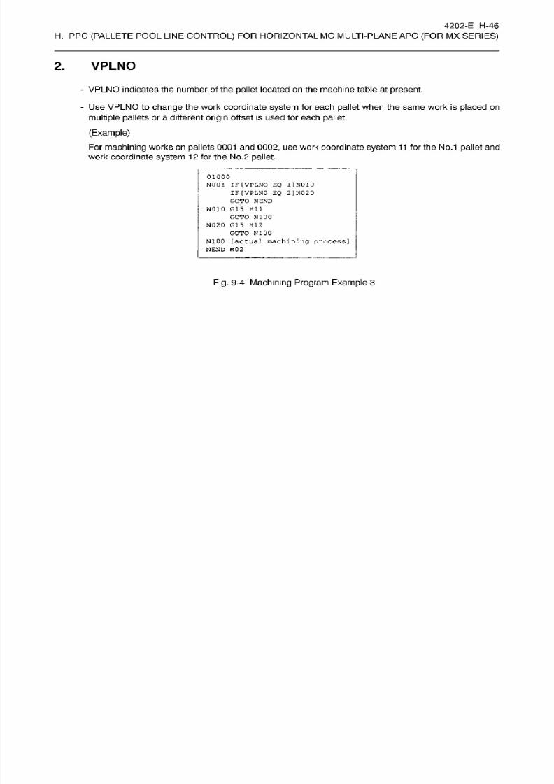
8/15/2019 Okuma Manuals 391
http://slidepdf.com/reader/full/okuma-manuals-391 261/397
4202-E H-46
H.
PPC
(PALLETE
POOL
LINE
CONTROL)
FOR HORIZONTAL MC MULTI-PLANE AP C
(FOR
MX
SERIES)
2.
VPLNO
-
VPLNO indicates
the number
of
the
pallet
located
on
the machine table
at
present.
-
Use VPLNO to
change
the work coordinate
system
for each
pallet
when the
same
work is
placed
on
multiple pallets
or
a
different
origin
offset
is
used
for
each
pallet.
(Example)
Fo r
machining
works on
pallets 0001
and
0002,
us e work
coordinate
system
11
for the No.1
pallet
and
work
coordinate
system
12
for the
No.2
pallet.
oiooo
N001
IF
(VPLNO
EQ
1]N010
IF
(VPLNO
EQ
2
]
N020
GOTO NEND
N010
G15
HI
1
GOTO N100
N020 G15
H12
GOTO
N100
N100
[actual
machining
process]
NEND M0 2
Fig.
9-4
Machining Program
Example
3
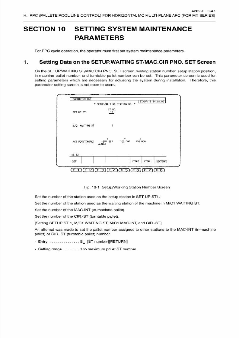
8/15/2019 Okuma Manuals 391
http://slidepdf.com/reader/full/okuma-manuals-391 262/397
4202-E
H-47
H.
PPC
(PALLETE
POOL
LINE
CONTROL)
FOR HORIZONTAL MC MULTI-PLANE AP C
(FOR
MX
SERIES)
SECTION 10 SETTING SYSTEM
MAINTENANCE
PARAMETERS
For PPC
cycle
operation,
the
operator
must
first
set
system
maintenance
parameters.
1. Setting
Data
on the
SETUP.
WAITING
ST/MAC.CIR
PNO. SET
Screen
On the SETUP.WAITING
ST/MAC.CIR
PNO. SET screen, waiting station
number,
setup
station position,
in-machine
pallet
number,
and
turntable
pallet
number can be
set.
This
parameter
screen is
used for
setting parameters
which
are necessary
for
adjusting
the
system during
installation.
Therefore,
this
parameter
setting
screen
is not open
to
users.
I
PARAMETER SET
I
97/07/15
14:10:00
*
SETUP/WAITING
STATION
NO.
*
ST-N0.
121
ET UP
ST
I
M/Cl
W A IT IN G S T
1
X
Z
AC T PO S
I
T
(WORK)
-551.552
100.000
100.000
A-Mtd
=S
12
ITEM
t
ITEM
i
[EXTEND]
ET
o
i
) (Fÿrÿ(Tÿ(TT)r r6 i rF-T)rF~r)
Fig.
10-1
Setup/Working Station
Number Screen
Set the number of the station used
as
the
setup
station
in
SE T
UP
ST1
.
Set the number of the station
used
as
the
waiting
stat ion of
the
machine
in
M/C1
WAITING
ST.
Set the number of the MAC-INT
(in-machine
pallet).
Set
the
number of
the
CIR.-ST
(turntable pallet).
[Setting
SETUP
ST
1,
M/C1
WAITING
ST,
M/C1
MAC-INT,
and
CIR.-ST]
An
attempt
was made to se t the
pallet
number assigned
to other stat ions to
the
MAC-INT (in-machine
pallet)
or CIR.-ST
(turntable pallet)
number.
S_
[ST number][RETURN]
1
to maximum
pallet
ST number
-
Entry
-
Setting range
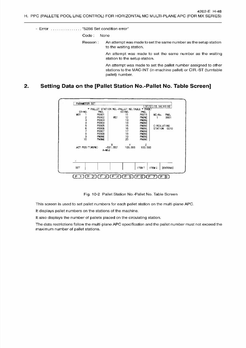
8/15/2019 Okuma Manuals 391
http://slidepdf.com/reader/full/okuma-manuals-391 263/397
4202-E H-48
H.
PPC
(PALLETE
POOL
LINE
CONTROL)
FOR HORIZONTAL MC MULTI-PLANE AP C
(FOR
MX
SERIES)
“5286 Se t
condition error”Error
Code
:
None
Reason
: An attempt
was madeto set the same number as the
setup
station
to the
waiting
station.
An
attempt
wa s
made to
set
the
same
number
as
the
waiting
station
to
the setup
station.
An
attempt
was made to set
the
pallet
number
assigned
to other
stations to the
MAC-INT
(in-machine
pallet)
or CIR.-ST
(turntable
pallet)
number.
2.
Setting
Data
on the
[Pallet
Station No.-Pallet
No.
Table
Screen]
PARAMETER SET
J.
97/07/15
14:10:00
*
PALLET
STATION NO .
-PALLET
NO. TABLE
ST-NO.
PAGE
ST-NO.
MS I
1
PNO.
PNO.
P0001
11
POOH
MC-No. PNO.
1 0001
PQ002
P0003
PQ004
P0005
P0006
P0007
P0008
PNONE
PNONE
WS1
12
PNONE
PNONE
PNONE
PNONE
PNONE
PNONE
PNONE
PNONE
PNONE
3
13
4
14
5 15
CIRCULATING
STATION
0010
15
7 17
e
18
9
19
10 20
X
Y
Z
ACT POSIT
(WORK)
-551.552
A-Mtd
100.000
100.000
ITEM
1
[EXTEND]
ET
ITEM
T
(Tji(Tÿ(Tÿ(TÿrFT)frÿfFÿrrr)
Fig.
10-2
Pallet Station No.-Pallet No. Table Screen
This
screen is used
to set
pallet
numbers
for
each
pallet station
on
the multi-plane
APC.
It
displays
pallet
numbers
on
the
stations of the
machine.
It also
displays
the
number
of
pallets placed on the
circulating
station.
The
data
restrictions
follow
the
multi-plane
APC
specification
and
the pallet
number
must not exceed the
maximum
number of
pallet
stations.
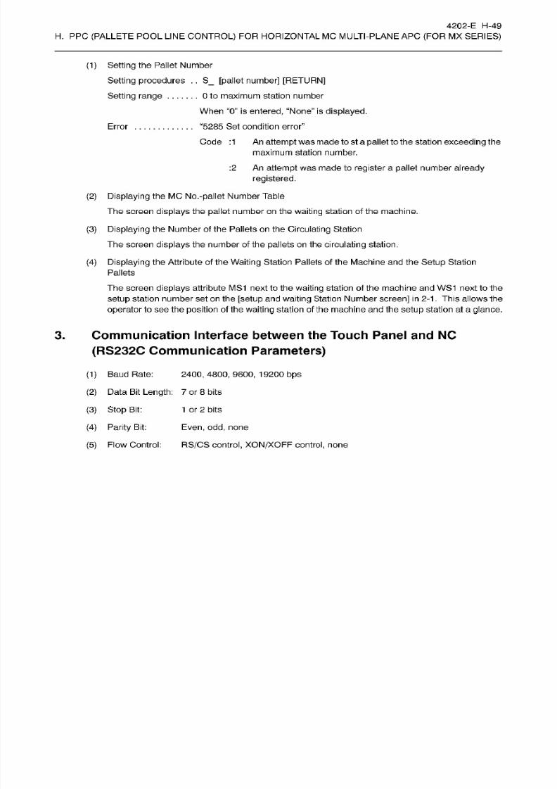
8/15/2019 Okuma Manuals 391
http://slidepdf.com/reader/full/okuma-manuals-391 264/397
4202-E H-49
H.
PPC
(PALLETE
POOL
LINE
CONTROL)
FOR HORIZONTAL MC MULTI-PLANE AP C
(FOR
MX
SERIES)
(1 )
Setting
the Pallet Number
Setting
procedures
. .
S_
[pa llet number] [RETURN]
Setting range
0 to maximum station number
When
“0”
is
entered,
“None” is
displayed.
“5285 Set condition error”
Code
:1
An
attempt
was made
to
st
a
pallet to
the station
exceeding
the
maximum station
number.
:2
An
attempt
was
made to
register
a
pallet number
already
registered.
Error
(2)
Displaying
the MC
No.
-pallet
Number
Table
The screen
displays
the
pallet
number on the
waiting
station of
the machine.
(3) Displaying
the Number of
the Pallets on the Circulating Station
The screen displays
the
number
of
the
pallets
on
the circulating
station.
(4)
Displaying
the Attribute of the
Waiting
Station Pallets of the Machine
and
the
Setup
Station
Pallets
The screen displays attr ibute
MS1 next to the
waiting station
of the
machine
an d WS1 next to
the
setup
station number set
on
the
[setup
and waiting Station Number
screen]
in 2-1
.
This
allows the
operator
to se e
the
position of the
waiting
station
of the
machine
and the
setup station
at a
glance.
3. Communication Interface
between
the
Touch Panel
and NC
(RS232C Communication
Parameters)
(1 )
Baud Rate:
2400,
4800, 9600,
19200 bps
(2 ) Data
Bit
Length:
7
or 8 bits
(3)
Stop
Bit:
(4) Parity
Bit:
1
or
2
bits
Even, odd,
none
(5)
Flow
Control:
RS/CS
control,
XON/XOFF
control,
none
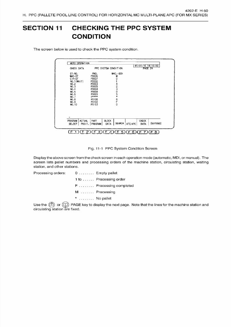
8/15/2019 Okuma Manuals 391
http://slidepdf.com/reader/full/okuma-manuals-391 265/397
4202-E H-50
H.
PPC
(PALLETE
POOL
LINE
CONTROL)
FOR HORIZONTAL MC MULTI-PLANE AP C
(FOR
MX
SERIES)
SECTION 11
CHECKING THE
PPC
SYSTEM
CONDITION
The
screen
below
is
used
to
check the PPC
system
condition.
I
AUTO
OPERATION
I
97/07/15
14:10:00
PP C
SYSTEM CONDITIONHECK DATA
PAGE
24
ST-NO.
MAC-ST
CIR-ST
NO .
1
(WAIT)
PNO.
MAC.
-SCH
P0006
P0007
P0002
P0003
P0005
P0004
P0008
P0001
p*#**
P0106
P0102
P0103
M
0
1
NO. 2 4
NO .
3 2
3
O.
4
0
O. 5
NO . 6
5
NO .
7
NO.
8
6
NO .
9
F
D
O. 10
BLOCK
ROGRAM
ACTUAL
PART
SELECT| POSIT.
I
PROGRAM
CHECK
[EXTEND]
EARCH
]
ATC/APC
ATA DATA
nrrifÿinrrTi[TTÿrFir)PHnrrT)iTin
Fig.
11-1
PPC
System
Condition
Screen
Display
the above
screen
from the check
screen
in each
operation
mode
(automatic, MDI,
or
manual).
The
screen lists pallet numbers an d
processing
orders of the machine
station, circulating
station,
waiting
station,
and
other
stations.
Processing
orders:
Empty
pallet
Processing
order
Processing
completed
Processing
No
pallet
Use the
(SB)
or
([g)
PAGE
key to
display the
next
page.
Note that the lines
for
the
machine station
and
circulating
station
are
fixed.
0
1
to
F
M

8/15/2019 Okuma Manuals 391
http://slidepdf.com/reader/full/okuma-manuals-391 266/397
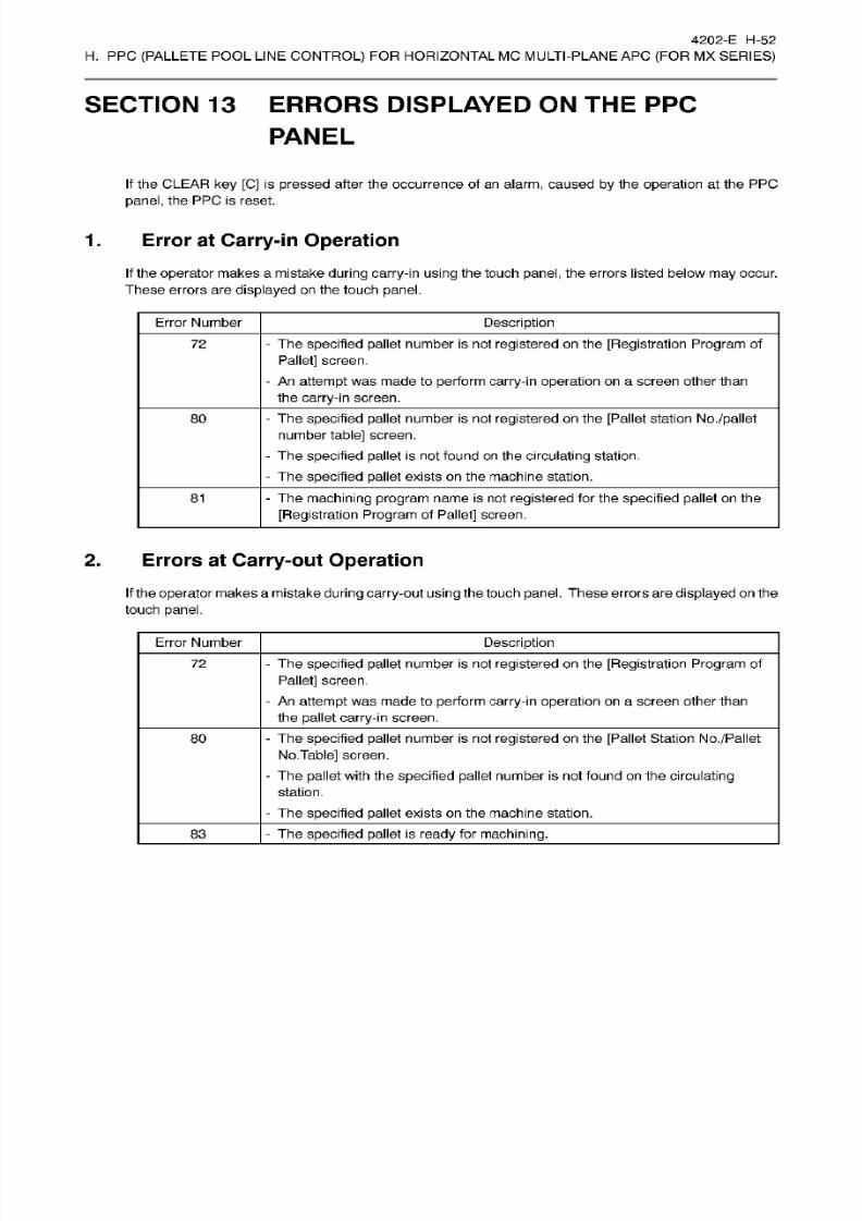
8/15/2019 Okuma Manuals 391
http://slidepdf.com/reader/full/okuma-manuals-391 267/397
4202-E H-52
H.
PPC
(PALLETE
POOL
LINE
CONTROL)
FOR HORIZONTAL MC MULTI-PLANE AP C
(FOR
MX
SERIES)
SECTION 13
ERRORS
DISPLAYED
ON
THE PPC
PANEL
If
the CLEAR
ke y
[C]
is pressed after
the
occurrence
of
an
alarm,
caused
by
the
operation
at
the PPC
panel,
the PPC is reset.
1.
Error at Carry-in
Operation
If the
operator
makes a mistake
during
carry-in
using
the touch panel, the
errors
listed
below may
occur.
These
errors
are
displayed
on the touch
panel.
Error
Number
Description
-
The specified pallet number
is
not
registered
on the
[Registration Program
of
Pallet] screen.
-
An
attempt
was
made to
perform carry-in
operation
on
a
screen
other than
the
carry-in
screen.
72
-
The specified pallet number is not
registered
on
the [Pallet station No./pallet
number
table]
screen.
-
The
specified
pallet
is
not found on
the
circulating
station.
-
The
specified pallet
exists on the machine
station.
80
-
The
machining program
name is not
registered
for
the
specified pallet
on the
[Registration Program
of
Pallet]
screen.
81
2.
Errors
at
Carry-out Operation
If
the operator makes amistake
during
carry-out
using
the
touch panel. These
errors are
displayed
on
the
touch
panel.
Error Number
Description
72
-
The
specified pallet
number is
not registered on
the
[Registration Program of
Pallet] screen.
-
An
attempt was
made to perform carry-in
operation on
a
screen
other than
the pallet carry-in
screen.
80
-
The
specified pallet
number
is
not
registered
on the
[Pallet
Station
No./Pallet
No.Table]
screen.
-
The
pallet with the
specified pallet
number is not found
on
the
circulating
station.
-
The specified pallet exists on the machine
station.
-
The specified pallet is
ready
for
machining.
3

8/15/2019 Okuma Manuals 391
http://slidepdf.com/reader/full/okuma-manuals-391 268/397
4202-E H-53
H.
PPC
(PALLETE
POOL
LINE
CONTROL)
FOR HORIZONTAL MC MULTI-PLANE AP C
(FOR
MX
SERIES)
3. Other
Errors
Error Number
Description
-
During the
execut ion of
carry-in
or
carry-out
operation,
the
pallet
number of
the pallet being carried
in
or
out
is changed
or
deleted on
the [Registration
Program of
Pallet] screen.
-
During the
execution of
machining,
the
pallet
number of
the objective
pallet
is
changed
or
deleted on the
[Registration Program
of
Pallet] screen.
99
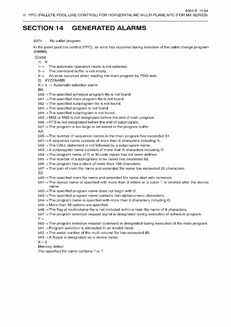
8/15/2019 Okuma Manuals 391
http://slidepdf.com/reader/full/okuma-manuals-391 269/397
4202-E
H-54
H.
PPC
(PALLETE
POOL
LINE
CONTROL)
FOR HORIZONTAL MC MULTI-PLANE AP C
(FOR
MX
SERIES)
SECTION
14
GENERATED ALARMS
2374
No
pallet
program
In
the
pallet pool
line
control
(PPC),
an
error
has
occurred
during
selection of the
pallet
change program
(09999).
[Code]
1) X:
1->
The automatic
operation
mode
is
not selected.
2->
The command
buffer is not empty.
3->
An
error
occurred when
reading
the
main
program by
PD O
task.
2)
XYZZAABB:
X
=
1
>
Automatic
selection
alarm
BB:
bitO->The specified
schedule
program
file is not found.
bit1->The
specified
main
program
file
is
not found.
bit2->The
specified
subprogram
file is not
found.
bit3->The specified
program
is not found.
bit4->The
specified
subprogram
is not
found.
bit5->M02
or M03 is not
designated
before
the
end of
main program.
bit6->RTS
is
not
designated
before the end of
subprogram.
bit7->The
program is
too
large
to be
stored in the program
buffer.
AA :
bitO->The
number of
sequence names
in
the main program has exceeded 31.
bit1—
>A
sequence name consists of more than 5
characters including
N.
bit2 >The
CALL
statement
is not
followed by
a
subprogram
name.
bit3
>
A
subprogram
name
consists
of
more
than
5
characters
including
0.
bit4->The
program
name of G or
M
code
macro
ha s not been defined.
bit5->The number
of
subprograms
to be called has exceeded 63.
bit6ÿ>The
program has
a b lock o f more
than 156 characters.
bit7 >The
sum
of main file name
and extended
file
name has
exceeded 20
characters.
ZZ :
bitO->The
specified
main file
name
and extended file
name start
with numerals.
The device
name
is
specified
with more
than
3
letters or a colon is omitted
after
the device
name.
bit1
bit2->The
specified program name does not begin
with O.
bit3->The
specified program name contains non-alphanumeric characters.
bit4->The
program
name
is
specified with
more
than
5
characters
including
0.
bit5->More
than
16 options
are
specified.
bit6->The flag
of multivolume file
is
not included within a main
file
name of 8
characters.
bit7->The
program
selection
request
signal
is
designated during
execution of schedule
program.
Y
=
bitO->The
program selection
request
command is
designated during execution
of the main
program.
bit1->
Program selection
is
attempted
in an
invalid mode.
bit2->The
serial
number of
the
multi volume
file
has exceeded
99 .
bit3->
A
floppy is
designated
as
a device name.
X
=
2
Memory
defect
The
specified file
name
contains
*
or
?.
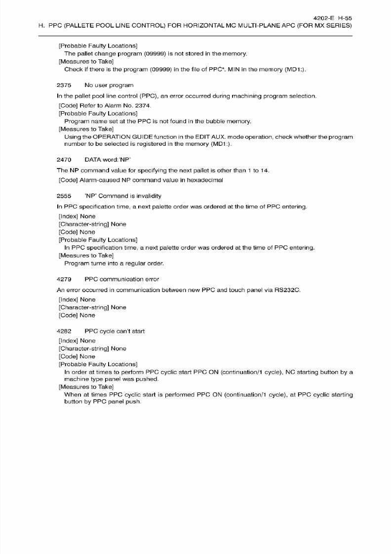
8/15/2019 Okuma Manuals 391
http://slidepdf.com/reader/full/okuma-manuals-391 270/397

8/15/2019 Okuma Manuals 391
http://slidepdf.com/reader/full/okuma-manuals-391 271/397
I.
PPC
(PALLETE
POOL
LINE
CONTROL)
FOR HORIZONTAL
MC MULTI-STATION
APC
(FOR
MC
SERIES)

8/15/2019 Okuma Manuals 391
http://slidepdf.com/reader/full/okuma-manuals-391 272/397
4202-
E
1-1
-A1
I. PPC (PALLETE
POOL
LINE
CONTROL)
FOR
HORIZONTAL MC MULTI-STATION AP C
(FOR
MC
SERIES)
SECTION
1
PREFACE
(1)
The
pallet pool
described in this
manual
consists
of the
multi-pallet
magazine
and the
setup
station where
workpieces
are
mounted onto and removed
from the
pallet.
(2)
The
pallet
pool line
control
(PPC)
operation panel
is installed
at
the
setup
station.
(3)
In this
system,
the
machining
sequence
is
determined by
the order the
workpieces
are mounted
onto
the
pallets
by
the
operator;
the
pallets
are
sequentially loaded
to the
machining
center
and
it
can
cut
workpieces
in succession
with
virtually
no
machine
stoppage
time.
(4)
Moreover,
the
machining sequence can be changed
fo r
workpieces
which
require
cutting
urgently
(urgent
workpiece).
(5)
This
example
is for a
12-pallet
magazine
with a
single
setup
station.
Machining
center
table
l
O
Pallet
pool
line
operation
panel
Setup station
0
:
represents
pallets.
Q
:
represents
carriers
without
pallets.
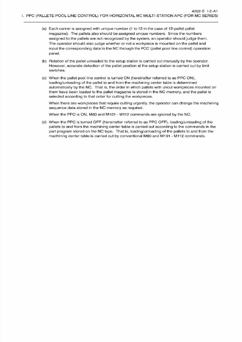
8/15/2019 Okuma Manuals 391
http://slidepdf.com/reader/full/okuma-manuals-391 273/397
4202-E
I-2-A1
I. PPC (PALLETE
POOL
LINE
CONTROL)
FOR
HORIZONTAL MC MULTI-STATION AP C
(FOR
MC
SERIES)
(a)
Each
carrier
is
assigned
with
unique number
(1
to
12
in
the
case of
1
2-pallet
pallet
magazine). The
pallets
also should be assigned
unique
numbers. Since the numbers
assigned
to
the
pallets
are
not
recognized by
the
system,
an
operator
should
judge
them.
The
operator
should also judge whether or not a
workpiece
is mounted on the
pallet
and
input
the
corresponding
data to the NC
through
the
PC C
(pallet
pool
line
control)
operation
panel.
(b)
Rotation of
the
pallet
unloaded to
the
setup
station is
carried
out
manually by the
operator.
However,
accurate detection
of the
pallet
position
at
the
setup
station is carried
out
by
limit
switches.
(c)
When
the
pallet
pool
l ine control is turned ON
(hereinafter
referred to as PPC
ON),
loading/unloading
of the
pallet
to and
from
the
machining
center
table is
determined
automatically by
the NC. That
is,
the order
in
which pallets
with
uncut
workpieces mounted on
them have been
loaded to the pallet
magazine is
stored
in
the NC
memory,
an d
the pallet is
selected
according
to that
order
for
cutting the
workpieces.
When
there
are
workpieces
that
require
cutting
urgently, the
operator
can
change
the
machining
sequence
data
stored in
the NC
memory
as
required.
When the PPC is ON, M60
an d
M101
-
M112
commands are
ignored by
the NC .
(d)
When
the
PPC is
turned OFF
(hereinafter
referred to
as
PP C
OFF),
loading/unloading
of the
pallets
to
an d
from the
machining
center table is
carried
ou t
according
to the commands
in
the
part
program
stored on
the NC tape.
That
is, loading/unloading
of the
pallets
to
an d from the
machining
center table
is carried out
by
conventional
M60
and
M101
-
M112
commands.

8/15/2019 Okuma Manuals 391
http://slidepdf.com/reader/full/okuma-manuals-391 274/397
4202-E I-3-A1
I.
PPC
(PALLETE
POOL LINE
CONTROL)
FOR HORIZONTAL
MC MULTI-STATION APC
(FOR
MC
SERIES)
SECTION 2 PPC
CYCLE
OPERATION
PROCEDURES
Fo r
executing
PPC
cycle
operation on
the
system,
fol low the
procedures
shown below.
(1)
Create the
PPC
cycle
operation
machining program.
(Section 3.)
1
(2)
Assign
PP C
cycle
operation
machining
programs
to pallet
numbers.
(Section
7.)
I
(3)
Carry
in
and out
pallets
to and from each ST.
(Section
5
and 6.)
I
(4)
Edit
machining
schedules.
(Section
8.)
I
Start
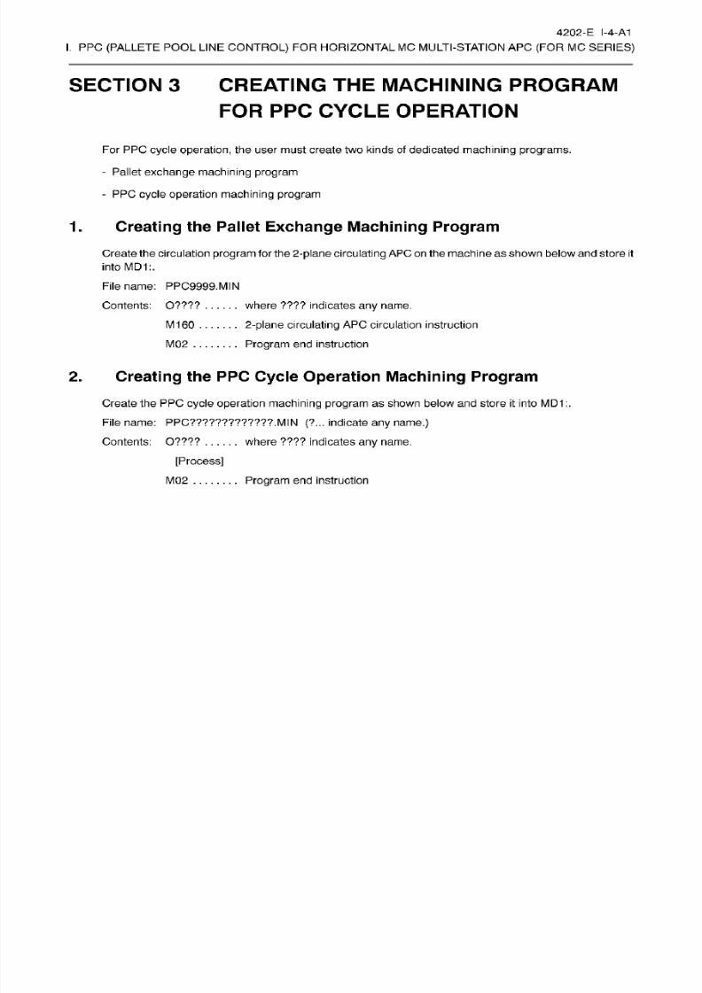
8/15/2019 Okuma Manuals 391
http://slidepdf.com/reader/full/okuma-manuals-391 275/397
4202-E
I-4-A1
I.
PPC
(PALLETE
POOL LINE
CONTROL)
FOR HORIZONTAL
MC MULTI-STATION APC
(FOR
MC
SERIES)
SECTION 3 CREATING
THE
MACHINING
PROGRAM
FOR PPC
CYCLE
OPERATION
For PPC
cycle
operation,
the
user
must create two
kinds
of
dedicated
machining
programs.
-
Pallet
exchange machining
program
-
PPC
cycle
operation
machining
program
1. Creating
the Pallet
Exchange
Machining
Program
Create the
circulation
program
for
the
2-plane
circulating
APC on
the
machine
as
shown
below and
store
it
into
MD1:.
Filename: PPC9999.MIN
Contents:
0????
where
????
indicates
any
name.
2-plane
circulating
AP C
circulation
instruction
Program
end instruction
M160
M02
2.
Creating
the
PPC Cycle
Operation
Machining
Program
Create
the
PP C
cycle
operation machining program
as
shown
below
and
store it
into
MD1 :.
File
name:
PPC?????????????.
MIN
(?...
indicate
an y name.)
where ????
indicates
any
name.
ontents:
O????
[Process]
M02
Program end
instruction

8/15/2019 Okuma Manuals 391
http://slidepdf.com/reader/full/okuma-manuals-391 276/397
4202-E I-5-A1
I.
PPC
(PALLETE POOL
LINE
CONTROL)
FOR
HORIZONTAL
MC
MULTI-STATION
AP C
(FOR
MC
SERIES)
SECTION
4 PPC PANEL OPERATION
The figure
below
shows
the PP C
panel. It
consists of
various switches
and
the
LCD
touch
panel.
pun
me
PALLET
IN
fePT
cVcLfe
PALLET
INP
No
PROCESSING
PROGRAM
PPC123456.MN
ERR
123.4
*ri
re t
P0001
1
Q
D
ns
WAITING SCHEDULE
PP C MODE
STOP
|
—
-
—
SCHEDULE
o
CONT
ONE
CYCLE
OFF
UTO
INTERRUFT
WAITING
cr*
EMPTY
PALLET
PPC CYCLE
START
N
o
DOOR
INTERLOCK
:
Select
Switch
O
:
Push
Switch
•
:
Emergency Stop
Switch
O
:
Lamp
O
RESTART EMG.
STOP
UT
o
Fig.
1-2
PP C
Panel
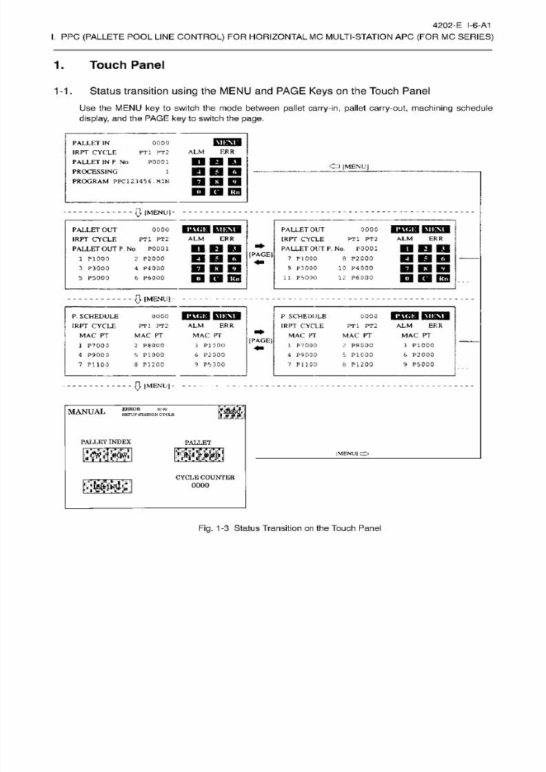
8/15/2019 Okuma Manuals 391
http://slidepdf.com/reader/full/okuma-manuals-391 277/397
4202-E I-6-A1
I.
PPC
(PALLETE POOL
LINE
CONTROL)
FOR
HORIZONTAL
MC
MULTI-STATION
AP C
(FOR
MC
SERIES)
1. Touch
Panel
1-1.
Status
transition
using
the
MENU and PAGE
Keys
on
the
Touch Panel
Use the M ENU
key
to switch the mode between
pallet
carry-in, pallet carry-out,
machining
schedule
display,
and the
PAGE key
to
switch
the
page.
\n:\i
ALLET
IN
1RPT
CYCLE
PALLET
IN P
No
PROCESSING
PROGRAM
PPC1234S6
.MIN
0000
ALM ERR
T1
PT2
P0001
Cn
|MENU]
D
n
D
w i
ra
vm
0
IMENUI-
PAGE
I
MEM
I
MEM
ALLET
OUT
IRPT
CYCLE
PALLET
OUT P. No
P000I
0000
PALLET
OUT
IRPT
CYCLE
PALLET
OUT
P
No
P0001
8
P2000
10 P 4000
12
P6Q00
0000
ALM
ER R
ALM
ER R
T1
PT2
PT1
PT2
[PAGE1
1 P1000
3
P3000
2
P2000
4
P4000
7
P1000
9
P3000
O
KB EH
D D E S
P6000
11
PS00O
P5000
$
(MENU)
E
. SCHEDULE
IRPT
CYCLE
MAC
PT
1
P7000
4
P9000
7
P1100
IHCKlMKM
P
SCHEDULE
IRPT CYCLE
MAC
PT
p\<;
i:
I
MI:\I
000
PT1 PT2
MAC
PT
0000
ALM
ERR
MAC.
PT
ALM
ERR
MAC PT
PT 1 PT2
MAC PT
[PAGE
2
P8000
5
P1000
3 P100O
6
P2000
1
P7000
2
P8000
5
P1000
3 P1000
4
P9000
6
P2000
9
P5000PI
200
9 PS
300 7 PU0D
8 P I 200
0
|MENU|- -
as
RROR
SETUP STATIONCYCLE
00
00
MANUAL
PALLET
INDEX
PALLET
[MENU]
O
CYCLE COUNTER
0000
mm
Fig.
1-3
Status
Transition
on
the Touch
Panel
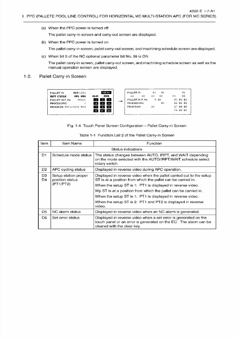
8/15/2019 Okuma Manuals 391
http://slidepdf.com/reader/full/okuma-manuals-391 278/397
4202-E
I-7-A1
I.
PPC
(PALLETE
POOL LINE
CONTROL)
FOR HORIZONTAL
MC MULTI-STATION APC
(FOR
MC
SERIES)
(a) When the PPC power is turned off
The pallet
carry-in screen
and
carry-out
screen
are
displayed.
(b) When the PPC power is
turned
on
The
pallet
carry-in
screen, pallet
carry-out
screen,
and
machining
schedule screen are
displayed.
(c)
When
bit
5 of
the
NC
optional parameter
bi t
No. 59
is
ON
The pallet
carry-in screen, pallet
carry-out
screen, and machining
schedule
screen
as
well
as
the
manual
operation
screen
are
displayed.
1-2. Pallet
Carry-in Screen
ALM
ERJt
PALLET
IN
A1
D1
D2
D3 D-1
PALLET
IN
P. No
P
B2
PROCESSING
PROGRAM
Cl
PALLET
IN
KPT
CYCLE
PALLET
IN
P.
NO .
POOC
1
PROCESSING
PROGRAM
PPC1234S6
MIM
ERR
i2 3-1
PT1 PT2
DS
D6
l
nun
El
E2
E3
E4 E5 E6
E-
E8 B9
Ea
Eb Ec
FO
HDD
El IB EH
A2
Fig.
1-4
Touch
Panel Screen
Configuration
-
Pallet
Carry-in
Screen
Table
1-1 Function
List
2
of the
Pallet
Carry-in
Screen
Item
Item Name Function
Status
indications
D1
Schedule
mode
status
The
status
changes
between
AUTO,
IRPT,
an d WAIT depending
on
the mode selected
with
the
AUTO/IRPT/WAIT
schedule select
rotary
switch.
D2
APC
cycling
status
Displayed in
reverse
video
during
APC
operation.
D3
Setup
station
proper
position
status
(PT1/PT2)
Displayed in
reverse
video when
the
pallet
carried out to the
setup
ST
is
at a posit ion from which
the
pallet
can be carried
in.
When the
setup ST is
1:
PT 1 is displayed
in
reverse
video.
Wp ST is at
a
position
from
which the
pallet
can be
carried
in.
When
the
setup
ST
is 1:
PT 1
is
displayed
in reverse
video.
When
the
setup
ST
is 2: PT 1 an d
PT2
is
displayed in
reverse
video.
D4
NC
alarm status
Displayed
in reverse video when an
NC
alarm is
generated.
5
D6
Set error status
Displayed
in reverse video when a set error is
generated
on the
touch
panel
or
an
error
is
generated
on the EC. The alarm can
be
cleared
with
the clear
key.
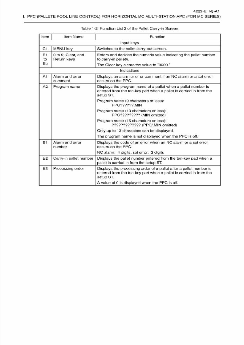
8/15/2019 Okuma Manuals 391
http://slidepdf.com/reader/full/okuma-manuals-391 279/397
4202-E I-8-A1
I.
PPC
(PALLETE
POOL LINE
CONTROL)
FOR HORIZONTAL
MC MULTI-STATION APC
(FOR
MC
SERIES)
Table
1-2
Function List
2
of the Pallet Carry-in
Screen
Item Item Name Function
Input
keys
C1 MENU key Switches
to the
pallet carry-out
screen.
0
to 9,
Clear,
and
Return
keys
E1 Enters and
decides the
numeric value
indicating
the
pallet
number
to
carry-in
pallets.
The
Clear
key clears the
value to
“0000.”
to
Ec
Indications
Displays an
alarm or error comment
if an
NC alarm or a set error
occurs
on the PPC.
A1
Alarm
and error
comment
A2
Program
name
Displays
the
program
name of a
pallet
when a
pallet
number is
entered from the ten-key pa d
when
a
pallet
is carried in
from
the
setup
ST.
Program
name
(9
characters or
less):
PPC??????.
MIN
Program
name
(13
characters or
less):
PPC?????????
(MIN omitted)
Program name
(16
characters or
less):
????????????? (PPC/.MIN
omitted)
Only up
to 13 characters
can
be
displayed.
The
program name
is
not
displayed
when the PP C is off.
B1
Alarm and error
number
Displays the code of
an
error when
an
NC alarm or a set error
occurs
on the PPC.
NC alarm:
4
digits,
set
error:
2 digits
Carry-in
pallet
number
Displays the
pallet
number
entered from the ten-key
pad
when
a
pallet
is carried
in
from the
setup
ST .
B2
Displays
the processing order
of
a
pallet
after
a
pallet number is
entered
from the
ten-key
pad
when
a
pallet
is carr ied in
from the
setup
ST.
A
value of 0
is displayed
when the PP C
is
off.
B3 Processing
order
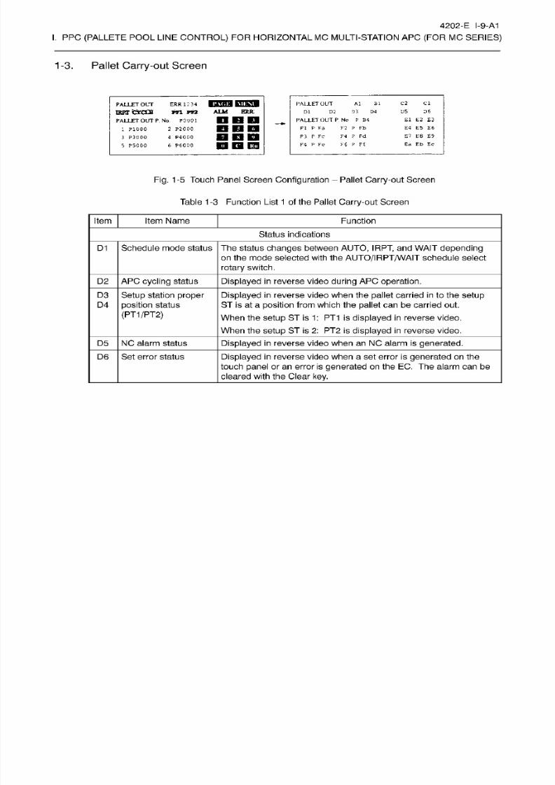
8/15/2019 Okuma Manuals 391
http://slidepdf.com/reader/full/okuma-manuals-391 280/397
4202-E I-9-A1
I.
PPC
(PALLETE
POOL LINE
CONTROL)
FOR HORIZONTAL
MC MULTI-STATION APC
(FOR
MC
SERIES)
1-3.
Pallet
Carry-out
Screen
ERR1234
njaasnsHi
m
m
ALM
ERR:
C2 C l
D5 D6
El
E2
£3
E4
E5 E6
£7
EB
£9
Ea Eb Ec
A1
31
D2
D3
D4
PALLET
OUT
P
No P
B4
FI
P
Fa
F2 P
Pb
F3
P FC
F4 P
Fd
F4
P
Fe F$
?
Ft
PA1J.ET OUT
ALLET OUT
1KFT CYCCH
PALLET OUT
P.
No
P0001
2
P2000
4 P4C00
6
P6030
D1
1
P10D0
3
PlOOO
5
P5000
DDD
IB
rm
Fig.
1-5
Touch Panel Screen
Configuration
Pallet
Carry-out
Screen
Table
1-3
Function List
1
of
the Pallet
Carry-out
Screen
Item Item Name
Function
Status
indications
Schedule mode status The status
changes
between AUTO,
IRPT,
and WAIT
depending
on
the mode selected with the
AUTO/I
RPT/WAIT
schedule select
rotary
switch.
D1
D2 APC
cycling
status
Displayed in reverse
video
during
APC
operation.
D3
Setup
station
proper
position
status
(PT1/PT2)
Displayed
in
reverse
video when
the
pallet
carried
in
to
the setup
ST
is
at a
position
from
which the pallet
can
be carried out.
When
the
setup
ST is 1
:
PT1
is
displayed in reverse
video.
When
the setup ST is
2:
PT 2 is displayed
in
reverse
video.
D4
D5 NC
alarm status
Displayed
in
reverse video when an
NC
alarm is
generated.
Se t error status6
Displayed in
reverse
video when
a set error is
generated on
the
touch
panel
or
an
error is
generated
on
the EC. The alarm
can be
cleared
with
the Clear
key.
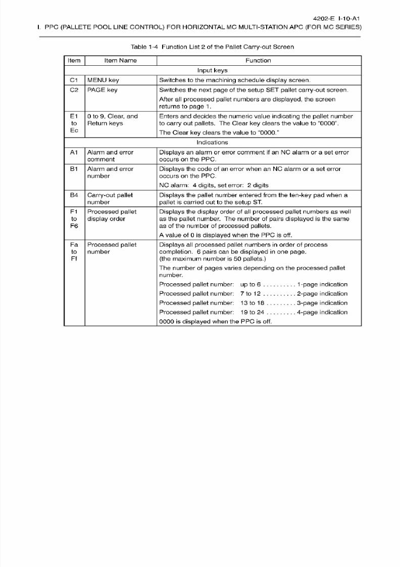
8/15/2019 Okuma Manuals 391
http://slidepdf.com/reader/full/okuma-manuals-391 281/397
4202-E I-10-A1
I.
PPC
(PALLETE
POOL LINE
CONTROL)
FOR HORIZONTAL
MC MULTI-STATION APC
(FOR
MC
SERIES)
Table
1-4
Function List
2
of
the
Pallet Carry-out Screen
Item Item Name Function
Input
keys
C1 MENU key Switches
to
the
machining
schedule
display
screen.
C2 PAGE
key
Switches
the
next page o f
the
setup
SE T
pallet carry-out
screen.
After all
processed pallet
numbers are
displayed,
the screen
returns to
page
1
.
E1
0
to
9,
Clear,
and
Return
keys
Enters
and
decides
the
numeric
value
indicating
the
pallet
number
to
carry
out
pallets.
The Clear
key
clears
the
value to “0000”.
The
Clear
ke y clears
the value to
“0000.”
to
Ec
Indications
A1 Alarm
and
error
comment
Displays
an
alarm or error comment
if an NC
alarm
or a
set
error
occurs on
the PPC.
B1
Alarm
and error
number
Displays
the code of
an
erro r when an NC
alarm
or a set error
occurs
on
the PPC.
NC alarm:
4 digits,
set error:
2 digits
B4
Carry-out pallet
number
Displays the
pallet
number
entered
from
the ten-key pa d
when a
pallet
is carried out to
the setup ST.
F1
Processed
pallet
display
order
Displays
the
display
order of all
processed
pallet numbers as well
as
the
pallet
number. The number of
pairs
displayed
is the
same
as
of
the
number of
processed pallets.
A
value of 0
is displayed
when the
PP C is off.
to
F6
Processed
pallet
number
Displays
al l
processed pallet
numbers
in
order of
process
completion.
6
pairs
can be
displayed in
one
page.
(the
maximum
number
is
50
pallets.)
The number of
pages
varies
depending on
the
processed
pallet
number.
Processed
pallet
number:
up
to 6
. . .
Processed
pallet
number:
7
to
12
.. .
Processed
pallet
number:
13
to
1
8
Processed
pallet
number:
1
9
to
24
0000
is
displayed
when the PPC is off.
Fa
to
Ff
1-page
indication
2-page
indication
3-page
indication
4-page
indication
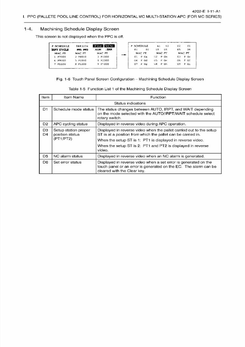
8/15/2019 Okuma Manuals 391
http://slidepdf.com/reader/full/okuma-manuals-391 282/397

8/15/2019 Okuma Manuals 391
http://slidepdf.com/reader/full/okuma-manuals-391 283/397
4202-E
I-12-A1
I.
PPC
(PALLETE
POOL LINE
CONTROL)
FOR HORIZONTAL
MC MULTI-STATION APC
(FOR
MC
SERIES)
Table
1-6
Function List
2
of the
Machining
Schedule
Display
Screen
Item Item Name Function
Input
keys
C1 MENU key Switches
to
the manual
operation
screen.
C2 PAGE
key
Switches to the next page of the
machining
schedule display
screen.
After al l
processed
pallet
numbers are
displayed,
the
screen
returns to the first
page.
Indications
A1
Alarm
and
error
comment
Displays an
alarm or error comment
if an NC
alarm
or a
set
error
occurs on
the PPC.
B1
Alarm and
error
number
Displays the code
of an error
when
an
NC alarm or a set
error
occurs
on
the
PPC.
NC
alarm:
4
digits,
set
error:
2
digits
B4
Carry-out pallet
number
Displays the pallet
number
entered
from
the ten-key pa d
when
a
pallet
is carried
out
to
the setup ST.
G1 Displays
the
processing
order
of
ready
pallet
numbers as well as
pallet
numbers.
The number of p[airs
displayed
is the same
as
the
number
of
ready
pallets.
A
value of
0
is displayed
when the PPC is off.
Ready
number
to
G9
Ga
Displays the processing
order
and
number of
ready
pallet
in the
NC
machining
schedule
in
a
list
table.
9
pairs
ca n be
displayed in
one
page.
(the
maximum number is
50
pallets.)
The number
of
pages
varies
depending
on
the ready pallet
number.
Pallet
number:
up
to
9
.
Pallet number:
10
to
18
Pallet number: 1
9
to
24
Ready
pallet
number
to
Gi
1-page
indication
2-page
indication
3-page
indication
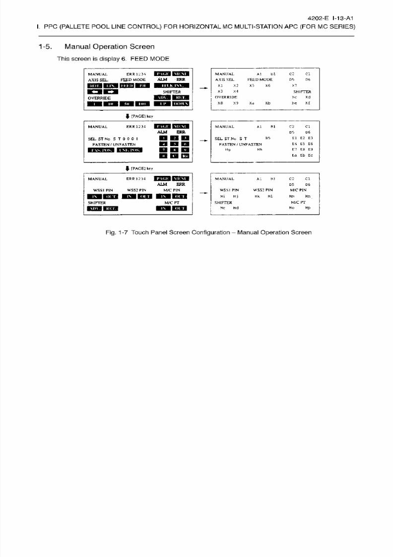
8/15/2019 Okuma Manuals 391
http://slidepdf.com/reader/full/okuma-manuals-391 284/397
4202-E I-13-A1
I.
PPC
(PALLETE POOL
LINE
CONTROL)
FOR
HORIZONTAL
MC
MULTI-STATION
AP C
(FOR
MC
SERIES)
1-5.
Manual
Operation Screen
This
screen is
display 6. FEED
MODE
SEIKO
u,
MANUAL
AXIS
SEL
Al til
c: ci
RR
1234
FEED
MODE
MANUAL
ALM
ER R
FELD MODE
D5 D6
XIS
SEL.
M
I.K
i\v.
X2
X5
X6
X7
I
l
II
OT.
X3
X4
HIFTER
SHIFTER
Xd
VERRIDE
Xc
IIV.
I RET.
VERRIDE
xf
8 X9 Xb
d
>.e
OWN
M)
J.
l
PAGE)
key
MANUAL
ERR
12
34
MANUAL
B
1
C2
Cl
l
ALM ERR
DS
S
£1 E2 E35
SEL
ST
No S
T
FASTEN
/
UNFASTEN
SEL. ST No
S T
0
0
0 I
FASTEN
/
UNFASTEN
E4 E5
EG
Hh
E7
Eg
E9
g
IM.
I
’CIS.
nnn
Ea Eb Ec
J-
[PAGE]
key
ER
R
1
2 3 4
r\<;i;
C2 Cl
ANUAL
MANUAL
Al
R2
ALM ERR
D5 D6
WSS2 PIN
WSSI
PI N
Hi Hj
SHIFTER
I
He
Hd
WSS2 PIN
MAT PINSSI PIN
M/C
PIN
Hk HI Hm
Hn
n
on
M/C
PT
/C
PTHIFTER
HO
HP
l> \ .
I
RET.
Fig.
1-7
Touch Panel
Screen
Configuration
Manual
Operation Screen
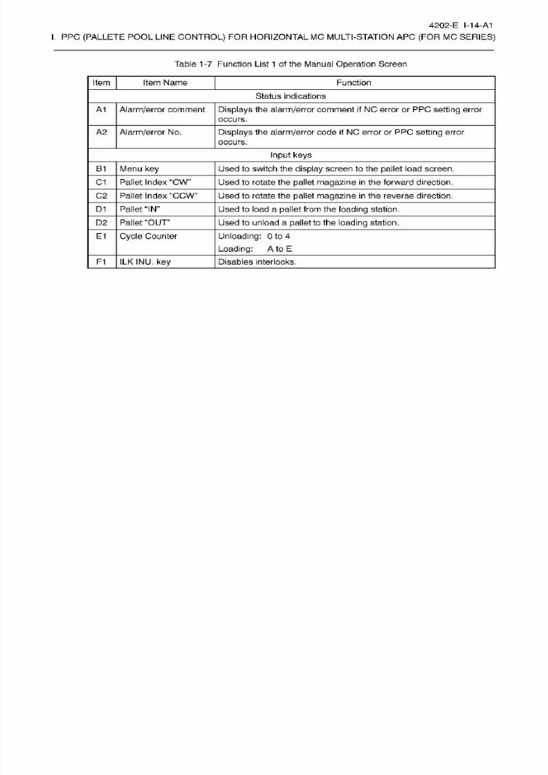
8/15/2019 Okuma Manuals 391
http://slidepdf.com/reader/full/okuma-manuals-391 285/397
4202-E
I-14-A1
I.
PPC
(PALLETE
POOL LINE
CONTROL)
FOR HORIZONTAL
MC MULTI-STATION APC
(FOR
MC
SERIES)
Table
1-7
Function List 1 of the Manual Operation
Screen
Item Item Name Function
Status
indications
A1
Alarm/error
comment
Displays
the
alarm/error
comment
if NC error
or
PPC
setting
error
occurs.
A2
Alarm/error
No. Displays the
alarm/error
code
if
NC
error
or PP C setting
error
occurs.
Input keys
B1
Menu
key
Used to switch the
display
screen to the pallet load screen.
C1 Pallet Index “CW” Used to rotate the pallet magazine in the
forward
direction.
C2 Pallet Index “CCW” Used to rotate the
pallet
magazine in
the reverse direction.
D1
Pallet
“IN”
Used
to
load a pallet
from
the
loading
station.
D2
Pallet
“OUT” Used
to
unload
a
pallet
to
the
loading
station.
E1
Cycle Counter
Unloading:
0to4
Loading:
AtoE
F1 ILK
INU.
ke y
Disables interlocks.

8/15/2019 Okuma Manuals 391
http://slidepdf.com/reader/full/okuma-manuals-391 286/397
4202-E I-15-A1
I.
PPC
(PALLETE
POOL LINE
CONTROL)
FOR HORIZONTAL
MC MULTI-STATION APC
(FOR
MC
SERIES)
2.
PPC Mode
Switch
Three
PPC modes
are
available:
continuous,
one
cycle,
and
off. This
section describes these PPC
modes.
Continuous
Used to run the machine
continuously according
to
the
PPC schedule.
Used to
process
one
pallet
only
of a PPC schedule.
Used
to disable PPC schedules.
One
cycle
Off
-
If
the
operation
mode is
changed
to PPC ON
(continuous/one cycle)
or PPC OFF
by
the PP C MODE
switch on the PP C
panel, both the
PPC side
and NC
side are reset.
3. Schedule Switch
The PPC
schedule
registration function
provides three
types of
schedules: automatic,
waiting,
and
interrupt. When pallets are carried
in,
the operator can
select either of these
types
with
this
schedule
switch to
register
various schedules for carried-in
pallets.
3-1
.
Automatic Schedule
Automatic
schedule
is normal
schedule.
At
pallet
carry-in, set
this
switch
to “Automatic” at
pallet
to
carry
in a
pallet,
and
the
pallet
is
added
to
the
pallet
registered
last
by
automatic schedule.
Set
the
PPC mode switch to “CONT.” or “One
cycle”
then
press
the “PPC CYCLE START
switch,
and the
machine
processes
pallets
according
to a
registered
schedule.
3-2.
Waiting
Schedule
Waiting
schedule
is
used to
pallets
ready
for
processing
on the
pallet
station but
process
them later.
Set this switch to “WAITING” when
carrying in
a
pallet,
the
pallet
is
added to the
one
registered
last
by
waiting
schedule.
If
it
takes much time to
process
them and the operator
wants
to
execute
processing
at
night,
the operator
prepares pallets
on
the ST for processing and
registers
them
by
the
waiting
schedule
in advance. The
operator
sets the PPC mode switch to “CONT.”
and
presses the PPC
CYCLE
START
switch, and
the
machine
processes
those pallets
after all
pallets registered in the
automatic schedule
complete.
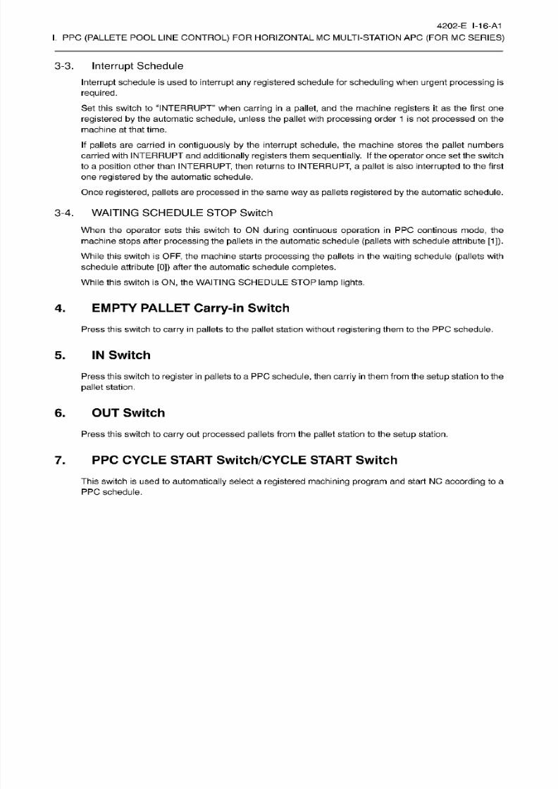
8/15/2019 Okuma Manuals 391
http://slidepdf.com/reader/full/okuma-manuals-391 287/397
4202-E I-16-A1
I.
PPC
(PALLETE
POOL LINE
CONTROL)
FOR HORIZONTAL
MC MULTI-STATION APC
(FOR
MC
SERIES)
3-3.
Interrupt
Schedule
Interrupt schedule is
used to interrupt any
registered
schedule for
scheduling
when urgent processing is
required.
Set this
switch
to
“INTERRUPT when
carring in
a pallet, and the machine
registers it
as
the
first
one
registered by
the automatic
schedule,
unless
the
pallet
with
processing
order
1
is
not
processed on
the
machine
at
that
time.
If
pallets are carried in contiguously
by
the
interrupt
schedule,
the machine
stores the
pallet
numbers
carried
with
INTERRUPT
and additionally registers them sequential ly. I f
the
operator
once set the switch
to a posit ion other than
INTERRUPT
then
returns
to
INTERRUPT,
a
pallet
is also
interrupted
to the f irst
on e
registered by the
automatic
schedule.
Once
registered,
pallets
are
processed in
the same
way as
pallets
registered by the
automatic
schedule.
3-4.
WAITING SCHEDULE STOP
Switch
When the
operator
sets
this switch
to ON
during continuous
operation
in
PPC
continous
mode,
the
machine
stops
after
processing
the
pallets
in
the
automatic
schedule
(pallets
with schedule attribute
[1]).
While this switch is
OFF,
the machine starts processing the
pallets
in the waiting schedule
(pallets
with
schedule
attribute [0])
after
the
automatic
schedule
completes.
While
this
switch
is
ON,
the
WAITING
SCHEDULE
STOP lamp
lights.
4.
EMPTY PALLET Carry-in
Switch
Press
this
switch to carry
in
pallets to the pallet station without registering
them
to
the
PP C schedule.
5.
IN Switch
Press this switch to
register
in
pallets
to a PPC
schedule,
then
carriy
in them from the
setup
station to the
pallet
station.
6.
OUT Switch
Press this switch to carry
out
processed pallets
from the
pallet
station to the
setup
station.
7.
PPC
CYCLE
START
Switch/CYCLE
START
Switch
Th is switch is used
to
automatically
select
a
registered machining program and
start
NC according
to a
PPC schedule.
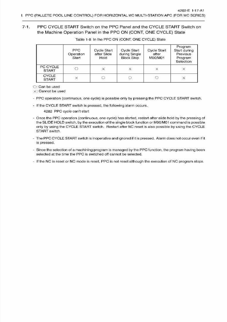
8/15/2019 Okuma Manuals 391
http://slidepdf.com/reader/full/okuma-manuals-391 288/397
4202-E
I-17-A1
I.
PPC
(PALLETE
POOL LINE
CONTROL)
FOR HORIZONTAL
MC MULTI-STATION APC
(FOR
MC
SERIES)
7-1 .
PPC CYCLE
START
Switch on the
PPC
Panel and
the
CYCLE
START
Switch on
the
Machine
Operation
Panel
in
the PPC
ON
(CONT,
ONE
CYCLE)
State
Table 1-8
In
the PPC ON
(CONT,
ONE
CYCLE)
State
Program
Start during
Previous
Program
Selection
PPC
Operation
Start
Cycle Start
after Slide
Cycle
Start
during Single
Block
Stop
Cycle
Start
after
MOO/M0
1old
PC
CYCLE
START
O
X
X
X X
CYCLE
START
O
o
o
x
O:
Can be used
x
: Cannot be used
-
PPC
operation (continuous,
one
cycle)
is
possible only by
pressing
the PP C CYCLE
START
switch.
-
If the
CYCLE
START
switch
is
pressed,
the
following
alarm occurs.
4282
PPC cycle
can’t
start
-
Once the PP C
operation
(continuous, one cycle)
ha s
started,
restart after slide hold
by
the
pressing
of
the SLIDE HOLD
switch, by the
execution of the
single
block function or
M00/M01
command is
possible
only by
using
the CYCLE
START switch. Restart
after
NC
reset is
also possible
by using
the
CYCLE
START switch.
- The PPC
CYCLE START
switch is
inoperative and ignored
if
itis
pressed. Alarm does not occur
even if
it
is
pressed.
- Since
the selection
of
a
machining
program
is
managed
by the
PP C function,
the
program
having
been
selected
at
the time
the PPC is
switched
off cannot be selected.
-
If the
NC is reset or NC mode is
reset,
PP C is
not
reset
although
the execution of NC
program stops.
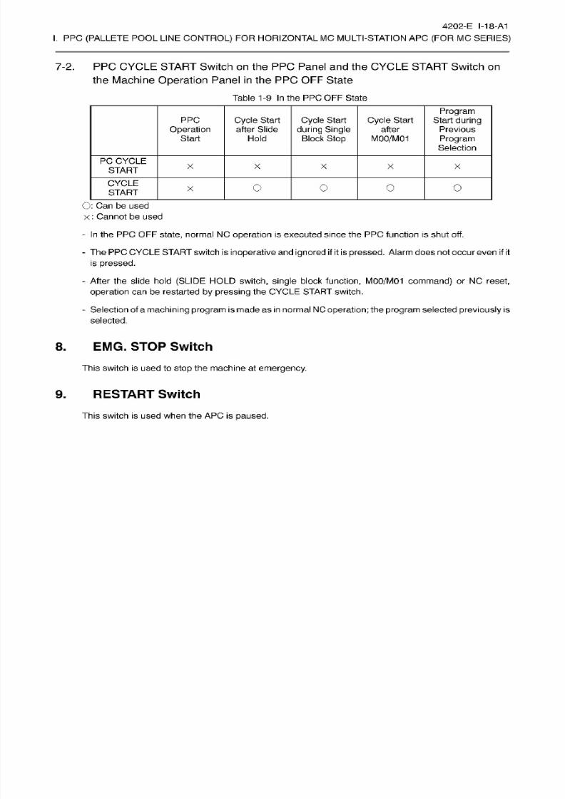
8/15/2019 Okuma Manuals 391
http://slidepdf.com/reader/full/okuma-manuals-391 289/397
4202-E I-18-A1
I.
PPC
(PALLETE
POOL LINE
CONTROL)
FOR HORIZONTAL
MC MULTI-STATION APC
(FOR
MC
SERIES)
7-2.
PPC CYCLE
START
Switch on the
PPC
Panel and
the
CYCLE
START
Switch on
the
Machine
Operation
Panel
in
the PPC OFF
State
Table
1
-9
In
the PPC OFF Sta te
Program
Start during
Previous
Program
Selection
PPC
Operation
Start
Cycle Start
after
Slide
Cycle
Start
during Single
Block
Stop
Cycle
Start
after
MOO/M0
1
old
PC CYCLE
START
X
X
X
X X
CYCLE
START
O O o o
O:
Can be used
x
:
Cannot be used
-
In the
P PC O FF
state,
normal NC
operation is
executed
since the PPC function is shut off.
-
The
PPC
CYCLE
START switch is
inoperative
and
ignored
if it is
pressed.
Alarm does not occur
even if
it
is pressed.
-
After
the
slide
hold (SLIDE HOLD switch,
single
block
function,
M00/M01
command) or
NC
reset,
operation
can
be
restarted
by
pressing
the
CYCLE START switch.
-
Selection of
a machining program is
made as
in normalNC
operation; the
program selected previously
is
selected.
8.
EMG.
STOP
Switch
This switch is
used
to
stop the
machine
at
emergency.
9.
RESTART
Switch
This switch is
used when the
AP C
is
paused.
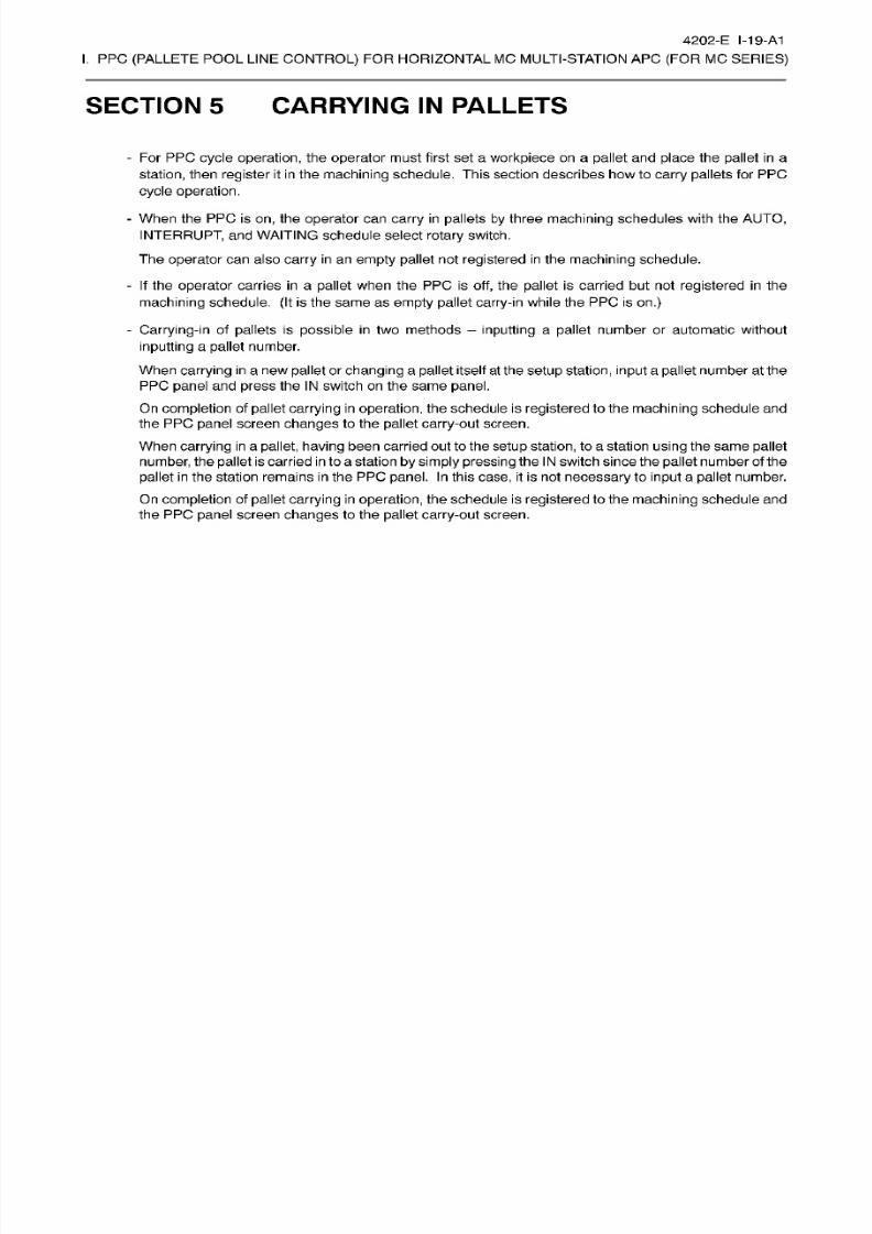
8/15/2019 Okuma Manuals 391
http://slidepdf.com/reader/full/okuma-manuals-391 290/397
4202-E I-19-A1
I.
PPC
(PALLETE
POOL LINE
CONTROL)
FOR HORIZONTAL
MC MULTI-STATION APC
(FOR
MC
SERIES)
SECTION 5 CARRYING
IN
PALLETS
-
Fo r
PP C cycle
operation,
the
operator
must
first
set a
workpiece
on a
pallet
and
place
the
pallet
in
a
station,
then
register
it in the
machining
schedule.
This
section
describes how to
carry pallets
for PPC
cycle operation.
-
When
the
PPC is
on,
the
operator
can
carry in pallets
by
three
machining
schedules
with
the
AUTO,
INTERRUPT,
and
WAITING schedule select
rotary
switch.
The operator
can also
carry in an
empty
pallet not registered in the machining schedule.
-
If
the operator
carries in
a
pallet
when
the PPC
is
off, the
pallet is
carried
but
not
registered in
the
machining schedule.
(It
is
the
same as
empty pallet carry-in
while the
PP C
is
on.)
-
Carrying-in
of
pallets is possible
in
two methods
-
inputting
a pallet number or automatic without
inputting
a pallet
number.
When
carrying
in
a
new
pallet or
changing
a pallet
itself
at
the setup
station,
input
a pallet number at the
PPC panel
and
press
the
IN
switch
on
the same
panel.
On
completion of pallet
carrying in
operation, the schedule is
registered
to the
machining
schedule and
the PP C
panel
screen
changes
to
the pallet
carry-out
screen.
When
carrying in
a
pallet,
having
been
carried
out
to the setup
station,
to
a
station
using
the
same pallet
number, the
pallet
is
carried in to
a station
by simply
pressing the IN
switch since
the
pallet
number of
the
pallet
in
the station
remains
in
the PPC
panel.
In
this
case,
it
is
not
necessary
to
input a
pallet
number.
On
completion
of
pallet carrying
in
operation,
the
schedule
is
registered
to the
machining
schedule
and
the PP C
panel
screen
changes
to the
pallet carry-out
screen.
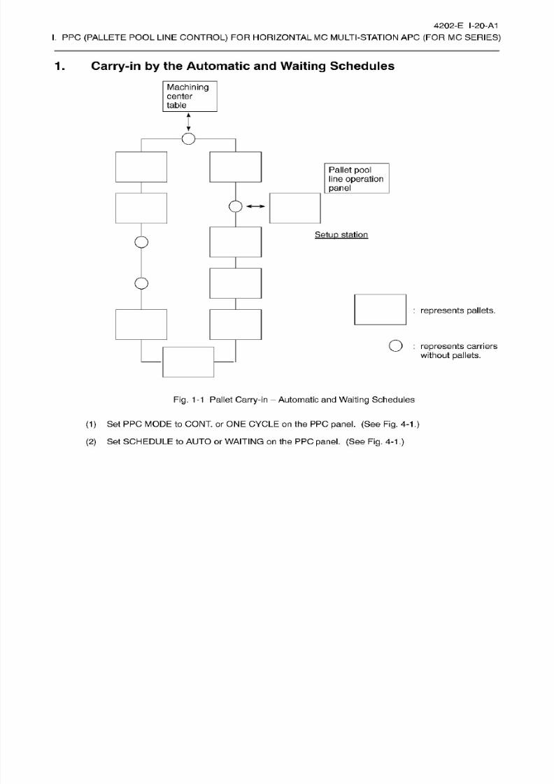
8/15/2019 Okuma Manuals 391
http://slidepdf.com/reader/full/okuma-manuals-391 291/397
4202-E I-20-A1
I.
PPC
(PALLETE
POOL LINE
CONTROL)
FOR HORIZONTAL
MC MULTI-STATION APC
(FOR
MC
SERIES)
1. Carry-in by the Automatic and
Waiting
Schedules
Machining
center
table
l
O
Pallet
pool
line operation
panel
Setup
station
0
:
represents pallets.
Q
:
represents
carriers
without
pallets.
Fig.
1-1
Pallet Carry-in
Automatic and
Waiting
Schedules
(1)
Set PPC
MODE to
CONT. or
ONE
CYCLE on
the
PPC
panel.
(See Fig. 4-1
.)
(2)
Set SCHEDULE to AUTO or WAITING
on
the PPC
panel.
(See
Fig. 4-1
.)
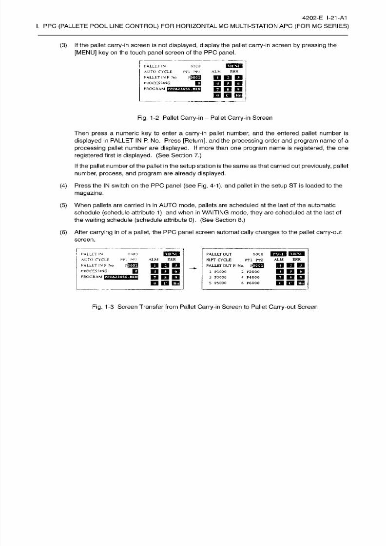
8/15/2019 Okuma Manuals 391
http://slidepdf.com/reader/full/okuma-manuals-391 292/397
4202-E
1-21
-A1
I.
PPC
(PALLETE
POOL LINE
CONTROL)
FOR HORIZONTAL
MC MULTI-STATION APC
(FOR
MC
SERIES)
(3) If
the
pallet
carry-in screen
is
not
displayed, display
the pallet
carry-in screen by pressing
the
[MENU] ke y on
the touch
panel
screen
of the PPC
panel.
PALLET
IN
AUTO CYCLE
PT1 PT: :
PALLET
IN
P
No
PROCESSING
PROGRAM
COCO
Al.M
ERR
r-QUJ
nan
n
K3
B
B
BO
19
KB
CO
Fig.
1-2
Pallet
Carry-in
Pallet
Carry-in
Screen
Then
press
a
numeric key
to enter a
carry-in
pallet
number,
and
the entered pallet
number is
displayed in PALLET IN
P.
No.
Press
[Return],
and
the processing
order
and
program name of a
processing
pallet
number
are
displayed.
If more than
on e
program
name
is registered,
the one
registered first is displayed. (See
Section
7.)
If
the pallet number
of
the
pallet
in
the
setup station
is
the
same
as
that carried
out
previously, pallet
number,
process, and
program
are
already
displayed.
(4)
Press the
IN
switch
on the
PPC panel (see
Fig.
4-1), and pallet
in
the
setup
ST is loaded to the
magazine.
(5) When
pallets
are carried
in
in AUTO mode, pallets are
scheduled at
the
last of the automatic
schedule
(schedule
attribute 1) ; and when
in
WAITING
mode, they
are scheduled
at
the last
of
the
waiting
schedule
(schedule
attribute
0).
(See
Section
8. )
(6) After carrying
in
of
a
pallet,
the PPC
panel
screen
automatically changes
to the
pallet
carry-out
screen.
ooco
IBWTW
MUW
PT l
PT2
ALM ERR
onaii
ALLET
IN
ALTO
CYCLE
PALLET
IN P
No
PROCESSING
PROGRAM
HS3T
GOOO
PALLET
OUT
IRPT CYCLE
PALLET
OUT
P. No.
pfTTTI
1
P1000
3
P:IOOO
5
PI.000
ALM
ER R
Tl FTP
pflrn
DBD
BOB
BBB
n
n
BO
2 P2000
4
P4000
6
P6000
BBB
n
Q
PW
Fig.
1-3
Screen Transfer from Pallet
Carry-in
Screen to Pallet
Carry-out
Screen
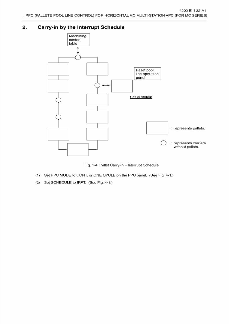
8/15/2019 Okuma Manuals 391
http://slidepdf.com/reader/full/okuma-manuals-391 293/397
4202-E
I-22-A1
I.
PPC
(PALLETE
POOL LINE
CONTROL)
FOR HORIZONTAL
MC MULTI-STATION APC
(FOR
MC
SERIES)
2.
Carry-in by the
Interrupt
Schedule
Machining
center
table
l
O
Pallet
pool
line operation
panel
Setup
station
0
:
represents pallets.
Q
:
represents
carriers
without
pallets.
Fig.
1-4
Pallet
Carry-in
Interrupt
Schedule
(1)
Set PPC
MODE to
CONT. or
ONE
CYCLE on
the
PPC
panel.
(See Fig. 4-1
.)
(2)
Set SCHEDULE to
IR PT. (S ee
Fig.
4-1
.)
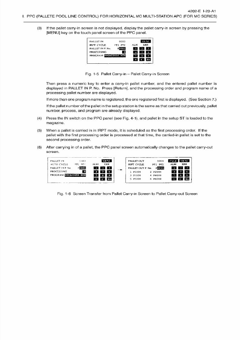
8/15/2019 Okuma Manuals 391
http://slidepdf.com/reader/full/okuma-manuals-391 294/397
4202-E I-23-A1
I.
PPC
(PALLETE
POOL LINE
CONTROL)
FOR HORIZONTAL
MC MULTI-STATION APC
(FOR
MC
SERIES)
(3) If
the
pallet
carry-in screen
is
not
displayed, display
the pallet
carry-in screen by pressing
the
[MENU] ke y on
the touch
panel
screen
of the PPC
panel.
1‘Al.LkT IN
IRPT
CYCLE
PALLET
IN
P.
No .
PROCESSING
PROGRAM
{522X035253
0000
FT l PT2
ALM
ERR
KB KI
MI
D
Dim
D
D CD
Fig.
1-5 Pallet Carry-in
-
Pallet
Carry-in
Screen
Then
press
a
numeric
key
to
enter a
carry-in pallet
number, and
the
entered
pallet
number is
displayed in PALLET IN P.
N o. Press
[Return],
and the
processing
order
and
program
name
of
a
processing pallet
number are
displayed.
If
more than one
program
name is
registered,
the
on e
registered
first
is
displayed. (See
Section
7.)
If
the
pallet
number
of
the
pallet
in
the
setup
station
is
the
same
as
that carried
out
previously, pallet
number,
process,
and
program
are
already
displayed.
(4)
Press the
IN
switch
on
the PPC
panel
(see
Fig.
4-1),
and
pallet
in the
setup
ST
is loaded
to the
magazine.
(5)
When
a
pallet
is carr ied in
in
IRPT
mode, it
is
scheduled as the f irst processing order. If the
pallet
with the first
processing
order
is
processed
at
that
time,
the carried-in
pallet
is
set to
the
second
processing order.
(6)
After
carrying in
of
a
pallet,
the PPC
panel
screen
automatically changes
to the
pallet
carry-out
screen.
PICT
oooo
pnnM
Ml PT2
ALM
ER R
PALLET
IN
ALTO
CYCLE
PALLET
IN
P
No
PROCESSING
PROGRAM
rni
PALLET OU T
IRPT CYCLE
PALLET
OU T
P NO .
pfflTW
2
P2000
«
P4000
6
R6000
0
000
ALM
ERR
T1
T
n
EIEI
m
a
1 P1000
3
P3000
5 PS
000
DEIO
m
E3
CO
ana
m
ra
nm
Fig.
1-6 Screen Transfer
from Pallet Carry-in
Screen to Pallet
Carry-out
Screen
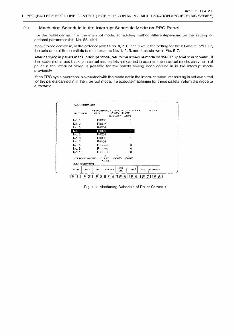
8/15/2019 Okuma Manuals 391
http://slidepdf.com/reader/full/okuma-manuals-391 295/397
4202-E
I-24-A1
I.
PPC
(PALLETE
POOL LINE
CONTROL)
FOR HORIZONTAL
MC MULTI-STATION APC
(FOR
MC
SERIES)
2-1.
Machining
Schedule
in
the Interrupt
Schedule
Mode
on
PPC
Panel
Fo r the
pallet
carried in
in
the
interrupt
mode,
scheduling
method differs
depending
on the
setting
for
optional parameter
(bit) No.
63, bi t
1 .
If
pallets are carried
in, in
the
order
of
pallet
Nos.
6, 7,8,
and
9 while the
setting
for
the bit above
is
“OFF”,
the schedule
of
these pallets is
registered as
No.
1
,
2,
3,
and
4
as shown
in
Fig.
5-7.
After
carrying in pallets
in the interrupt
mode,
return theschedule mode
on
the PPC
panel
to automatic.
If
the mode is
changed
back
to
interrupt
and pallets
are carried
in
again
in
the
interrupt mode,
carrying
in
of
pallet
in the
interrupt
mode
is
possible
for the
pallets
having been carr ied in in
the
interrupt
mode
previously.
If
the PPC
cycle
operation
is executed
with
the
mode
set in the
interrupt mode, machining is
not executed
for the
pallets
carried
in
in
the interrupt
mode. To
execute machining for these
pallets,
return
the
mode to
automatic.
PARAMETER SET
*
MACHINING
SCHEDULE
OF
PALLET
*
SCHEDULE
ATT
0:
WAIT
/
I;
AUTO
PAGE
I
MAC. -SCH. PN O
No. 1
No.
2
No.
3
P0006
P0007
P0008
1
1
1
No .
4
P0009
1
No .
5
No. 6
No.
7
No .
8
No. 9
No .
10
P0001
P0002
P0003
P****
P****
1
1
1
0
0
P:
0
X
Y
Z
ACT POSIT
(WORK)
-551.552 100.000
100.000
A-Mtd
=MV_7[RETURN)
SC H
ITEM
T
ITEM
4-
[EXTENDI
EL SEARCH
OVE ADD
CHC
i
gji(TT)rrT)rFTÿ(TTi(TÿrF~T)rF~Bi
Fig.
1-7 Machining
Schedule of Pallet Screen
1
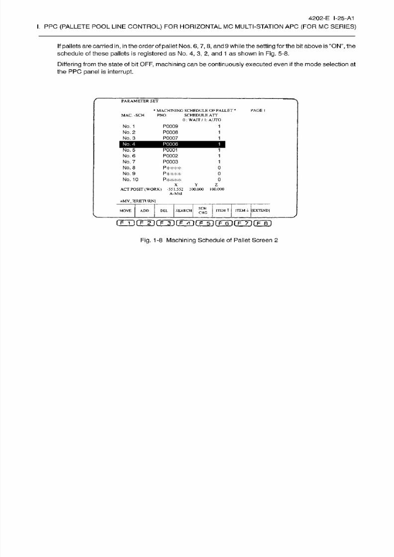
8/15/2019 Okuma Manuals 391
http://slidepdf.com/reader/full/okuma-manuals-391 296/397
4202-E I-25-A1
I.
PPC
(PALLETE
POOL LINE
CONTROL)
FOR HORIZONTAL
MC MULTI-STATION APC
(FOR
MC
SERIES)
If
pallets are carried
in, in
the order of palletNos.
6,
7,
8, and
9 while the
setting for
the bit above is
“ON”,
the
schedule
of these
pallets
is
registered
as
No.
4,
3,
2,
and 1 as shown
in Fig.
5-8.
Differing
from
the state of bit OFF,
machining
can
be continuously executed
even
if
the
mode selection at
the PP C
panel
is
interrupt.
PARAMETER
SET
*
MACHINING
SCHEDULE
OF PALLET
*
SCHEDULE
ATT
0: WAIT
/ I:
AUTO
PACE
I
MAC.
-SCH.
PNO.
No.
1
No. 2
No. 3
P0009
P0008
P0007
1
1
1
No.
4
P0006
1
No. 5
No. 6
No. 7
No.
8
No. 9
No.
10
P0001
P0002
P0003
P****
1
1
1
0
0
0
z
Y
AC T
POSIT
(WORK)
-551 .552 100 .000
100.000
A-Mtd
=MV_7[
RETURN]
SC H
ITEM
T
ITEM 4-
[EXTEND]
OV E
ADD DEL
SEARCH
CHG
(TTifTTirrT)rFÿfTTÿrFT)rÿT)rF~s~)
Fig.
1-8
Machining
Schedule of Pallet
Screen 2
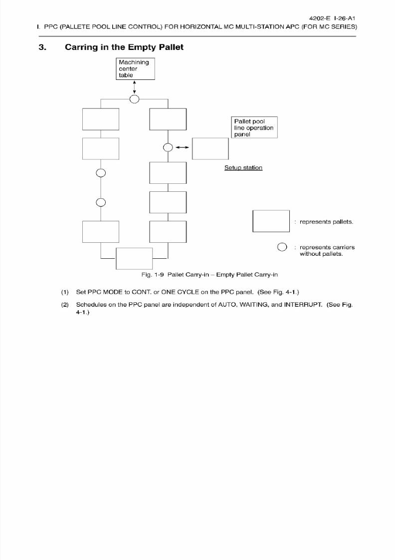
8/15/2019 Okuma Manuals 391
http://slidepdf.com/reader/full/okuma-manuals-391 297/397
4202-E I-26-A1
I.
PPC
(PALLETE
POOL LINE
CONTROL)
FOR HORIZONTAL
MC MULTI-STATION APC
(FOR
MC
SERIES)
3. Carring in the
Empty
Pallet
Machining
center
table
l
O
Pallet
pool
line operation
panel
Setup
station
0
:
represents pallets.
Q
:
represents
carriers
without
pallets.
Fig.
1-9 Pallet Carry-in
Empty Pallet Carry-in
(1)
Set PPC
MODE
to CONT. or
ONE
CYCLE on
the
PPC
panel.
(See Fig. 4-1
.)
(2)
Schedules on
the PPC
panel
are
independent
of
AUTO,
WAITING,
and INTERRUPT.
(See
Fig.
4-1.)
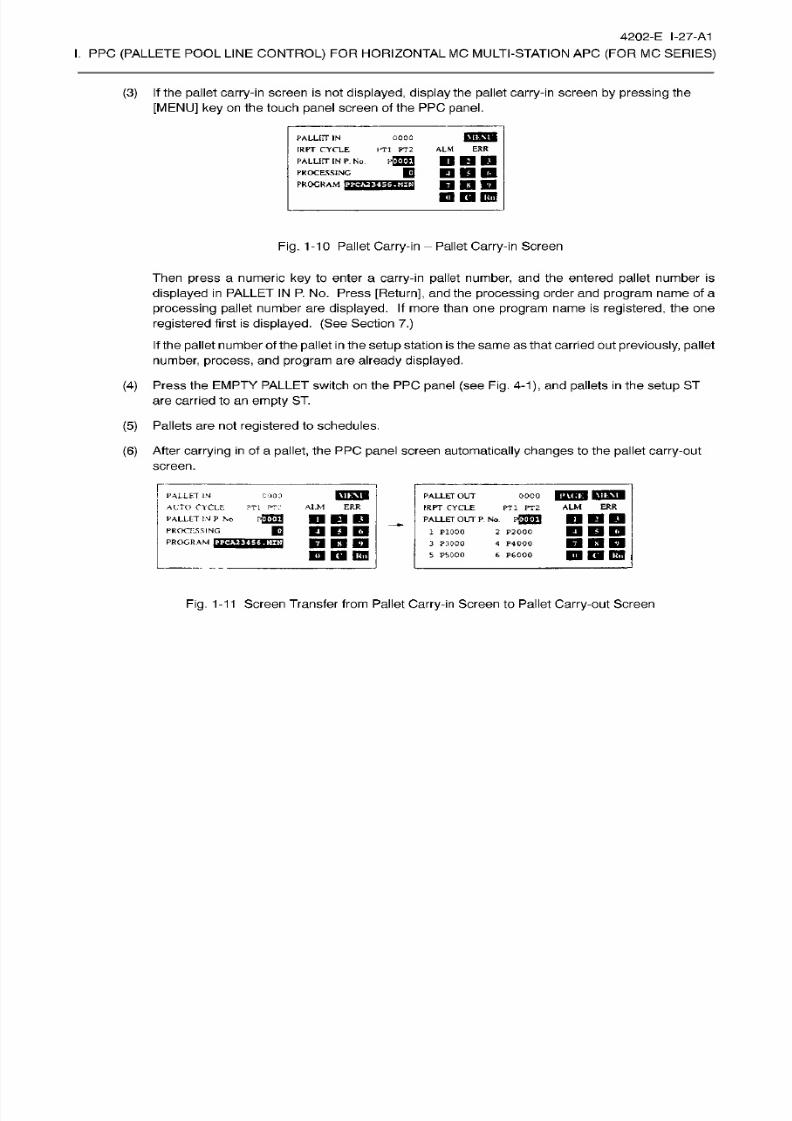
8/15/2019 Okuma Manuals 391
http://slidepdf.com/reader/full/okuma-manuals-391 298/397
4202-E
I-27-A1
I.
PPC
(PALLETE
POOL LINE
CONTROL)
FOR HORIZONTAL
MC MULTI-STATION APC
(FOR
MC
SERIES)
(3) If
the
pallet
carry-in screen
is
not
displayed, display
the pallet
carry-in screen by pressing
the
[MENU] ke y on
the touch
panel
screen
of the PPC
panel.
Milkutl
ALLITT IN
IRPT
CYCLE
PALLET IN
P.
No
PROCESSING
PROGRAM
OOOQ
ITl
PT2
ERR
LM
H<M«H
KB
KB
HDSD
nnn
U
Dl
IW B
Fig. 1-10 Pallet Carry-in
-
Pallet
Carry-in Screen
Then
press
a numeric
key
to enter a
carry-in pallet
number,
and
the
entered
pallet
number
is
displayed
in
PALLET IN P. No.
Press
[Return],
and the
processing
order an d
program name
of a
processing
pallet number
are
displayed.
If more
than on e
program
name is
registered,
the
on e
registered
first is
displayed. (See
Section
7.)
If
the
pallet
number
of
the
pallet
in
the
setup
station
is
the
same
as
that carried
out
previously, pallet
number,
process,
and
program
are
already displayed.
(4)
Press the
EMPTY
PALLET
switch
on
the PP C
panel
(see Fig.
4-1), an d pallets
in
the
setup
ST
are
carried to
an
empty
ST.
(5)
Pallets are not
registered
to schedules.
(6)
After
carrying in
of a
pallet,
the
PPC
panel
screen
automatically
changes
to the
pallet carry-out
screen.
ooco
BLITHB
MIHJ
PT1
PT2
ALM
ERR
PALLET
IN
AUTO
CYCLE
PALLET IN
P
No
PROCESSING
PROGRAM
PALLET
OUT
IRPT CYCLE
PALLET
OU T
P.
No.
pflHJ
2 P2000
4
P4000
6 P6000
MOO
ALM
ER R
TI
PT:I
nan
nan
nnn
m
QI
mo
1 P1000
3
P3000
5 PS 000
nnn
n
D E33
Fig.
1-11
Screen
Transfer
from Pallet
Carry-in
Screen to
Pallet
Carry-out
Screen
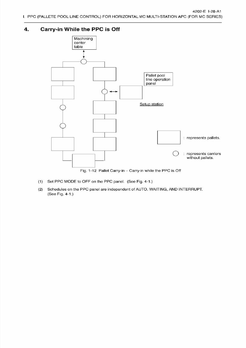
8/15/2019 Okuma Manuals 391
http://slidepdf.com/reader/full/okuma-manuals-391 299/397
4202-E I-28-A1
I.
PPC
(PALLETE
POOL LINE
CONTROL)
FOR HORIZONTAL
MC MULTI-STATION APC
(FOR
MC
SERIES)
4.
Carry-in While the
PPC is Off
Machining
center
table
l
O
Pallet
pool
line operation
panel
Setup
station
0
:
represents pallets.
Q
:
represents
carriers
without
pallets.
Fig. 1
-12 Pallet Carry-in
Carry-in while
the PPC is Off
(1)
Set PPC
MODE
to OFF
on
the PPC
panel. (See
Fig.
4-1
.)
(2)
Schedules on
the PPC
panel
are
independent
of
AUTO,
WAITING,
AN D
INTERRUPT.
(See
Fig.
4-1.)
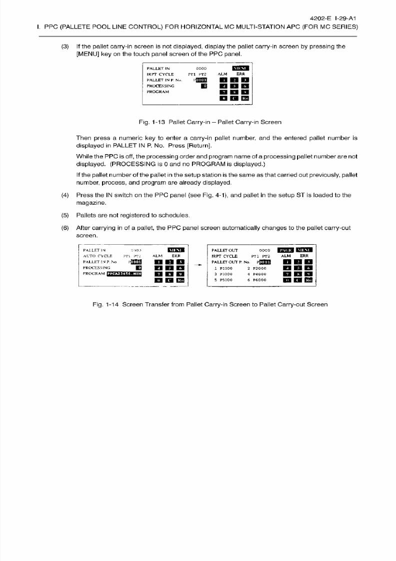
8/15/2019 Okuma Manuals 391
http://slidepdf.com/reader/full/okuma-manuals-391 300/397
4202-E I-29-A1
I.
PPC
(PALLETE
POOL LINE
CONTROL)
FOR HORIZONTAL
MC MULTI-STATION APC
(FOR
MC
SERIES)
(3) If
the
pallet
carry-in screen
is
not
displayed, display
the pallet
carry-in screen by pressing
the
[MENU] ke y on
the touch
panel
screen
of the PPC
panel.
MULT
ALLET
IN
IRPT
CYCLE
PALLET
IN P. No.
PROCESSING
PROGRAM
0000
PT1
PT 2
ER R
LM
DBD
DDD
M l
IB
IBB
Fig.
1-13 Pallet
Carry-in
- Pallet
Carry-in
Screen
Then
press
a
numeric
key
to
enter a
carry-in pallet
number, and
the
entered
pallet
number is
displayed in PALLET
IN
P.
N o. P ress
[Return],
While the PPC
is
off,
the
processing
order
an d
program
name
of a
processing
pallet
number are not
displayed. (PROCESSING
is
0
and no PROGRAM is
displayed.)
If
the
pallet
number
of
the
pallet
in
the
setup
station
is
the
same
as
that carried
out
previously, pallet
number,
process,
and
program
are
already
displayed.
(4)
Press the
IN
switch
on
the PPC
panel
(see
Fig.
4-1),
and
pallet
in the
setup
ST
is loaded
to the
magazine.
(5)
Pallets
are not
registered
to schedules.
(6)
After carrying
in
of
a
pallet,
the
PP C
panel
screen
automatically
changes
to the
pallet
carry-out
screen.
coco
iPTHW
PTPB
PT l
PT2
ALM
ERR
MIHBU
ALLET
IN
ALTO
CYCLE
PALLET
OUT
IRPT
CYCLE
_
PALLET
OUT
P No .
pfTffl
1
P1000
3
P:IOOO
5 PS
000
(2000
ERR
TL PT: ALM
P2U]
DBD
ALLET
IN
P No
PROCESSING
PROGRAM
HOT
E
2
P2000
4
P40O0
6 P6000
DDD
D E9
CO
DDD
n
O
EH
Fig.
1-14 Screen
Transfer
from Pallet Carry-in Screen to Pallet Carry-out Screen

8/15/2019 Okuma Manuals 391
http://slidepdf.com/reader/full/okuma-manuals-391 301/397
4202-E I-30-A1
I.
PPC
(PALLETE
POOL LINE
CONTROL)
FOR HORIZONTAL
MC MULTI-STATION APC
(FOR
MC
SERIES)
SECTION 6 CARRYING
OUT
PALLETS
-
This
section describes
how
to
carry
out
processed pallets
from
each
ST
to
the
setup
ST.
-
While the PPC is
on ,
only
processed pallets and pallets carried into with
EMPTY
PALLET
can
be
carried
out.
-
While the PPC is
off,
OUT
is effective for
all
pallets
except for
the on e
in
process.
When scheduled
pallets
are carried
out,
their
processing
order
is
deleted.
-
Carrying-out
of
pallets is
possible in
two methods
inputting
a pallet number or automatic without
inputting
a
pallet
number.
When carrying
out a
specific pallet
to the
setup
station, input
the
pallet
number of the
pallet
to
be
carried
out an d press
the OUT switch on
the
PP C
panel.
On
completion
of
pallet
carrying
out
operation,
the PPC
panel
screen changes
to the
pallet
carry-in
screen
automatically.
To
carry
out a
processed pallet
to the
setup
station,
the
operation
is
possible
by simply pressing
theOUT
switch
on
the PPC panel.
In
this
operation,
the
pallet
having
the
smallest
pallet
number
among
the
processed
pallets
is
automatically
searched.
On completion
of pallet
carrying
out operation,
the
PP C
panel screen changes
to
the
pallet
carry-in
screen automatically.
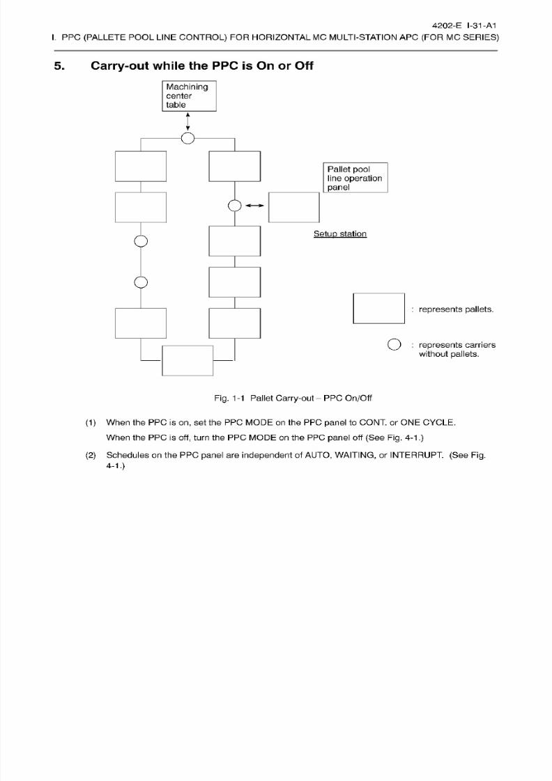
8/15/2019 Okuma Manuals 391
http://slidepdf.com/reader/full/okuma-manuals-391 302/397
4202-E
1-31
-A1
I.
PPC
(PALLETE
POOL LINE
CONTROL)
FOR HORIZONTAL
MC MULTI-STATION APC
(FOR
MC
SERIES)
5. Carry-out
while
the PPC
is
On
or
Off
Machining
center
table
l
O
Pallet
pool
line operation
panel
Setup
station
0
:
represents pallets.
Q
:
represents
carriers
without
pallets.
Fig. 1
-1 Pallet Carry-out
PP C
On/Off
(1)
When
the
PPC
is
on,
set
the
PPC MODE on
the
PPC
panel
to
CONT. or
ONE CYCLE.
When
the
PPC
is
off,
turn
the
PPC MODE
on
the PPC
panel
off
(See Fig.
4-1.)
(2)
Schedules on
the PPC
panel
are
independent
of
AUTO,
WAITING,
or INTERRUPT.
(See
Fig.
4-1.)
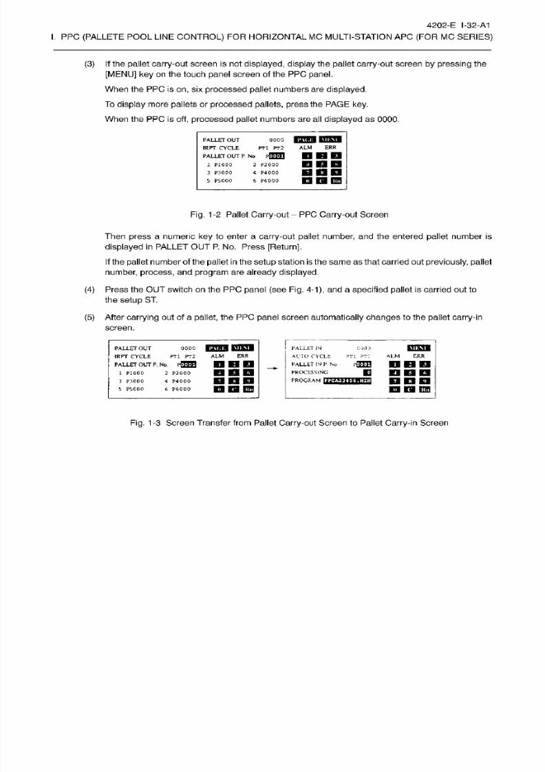
8/15/2019 Okuma Manuals 391
http://slidepdf.com/reader/full/okuma-manuals-391 303/397
4202-E I-32-A1
I.
PPC
(PALLETE
POOL LINE
CONTROL)
FOR HORIZONTAL
MC MULTI-STATION APC
(FOR
MC
SERIES)
(3) If
the
pallet
carry-out
screen is
not
displayed, display
the
pallet
carry-out
screen by pressing
the
[MENU] ke y on
the touch
panel
screen
of the PPC
panel.
When the
PPC
is
on ,
six
processed
pallet
numbers are
displayed.
To
display more
pallets
or
processed
pallets,
press
the PAGE
key.
When the PPC is
off,
processed pallet
numbers
are
al l
displayed
as
0000.
oooo
KQB3I
PT1
PT2 ALM
ER R
PALLET
OUT
IRPT
CYCLE
PALLET
OU T
P
No
rffTO
1
P1000
2 P2000
4 P4000
€
P6000
UDD
Ml
m
fW\
3 P:IOOO
5 P5000
Fig.
1-2 Pallet Carry-out PP C Carry-out Screen
Then
press
a
numeric
key
to
enter
a
carry-out
pallet
number,
and the entered
pallet
number
is
displayed in PALLET
OUT
P. No.
Press
[Return],
If
the pallet number of the
pallet
in
the
setup
station
is
the same as that carried
out
previously,
pallet
number,
process,
and
program
are
already displayed.
(4)
Press the OUT switch on the PPC
panel
(see
Fig.
4-1),
and
a
specified pallet is carried ou t to
the
setup
ST.
(5)
After carrying
out
of a
pallet,
the PPC
panel
screen
automatically changes
to the
pallet
carry-in
screen.
oooo
nrTHi
P333
PTl
PT2
ALM
ERR
PALLET
OUT
IRPT
CYCLE
PALLET OUT
P.
No .
pffTO
1 P1000
3
P3000
5
PSCOO
PALLET
JN
ALTO
CYCLE
?T1
PT 2
PALLET IN
P. No
PROCESSING
PROGRAM
(222
COO
3
ALM
ERR
DHD
PEHJ
DOD
nan
n
w i i?w
2 P2000
nan
P4000
19 19
DO
P6000
Fig.
1-3 Screen Transfer
from
Pallet
Carry-out
Screen
to
Pallet Carry-in
Screen
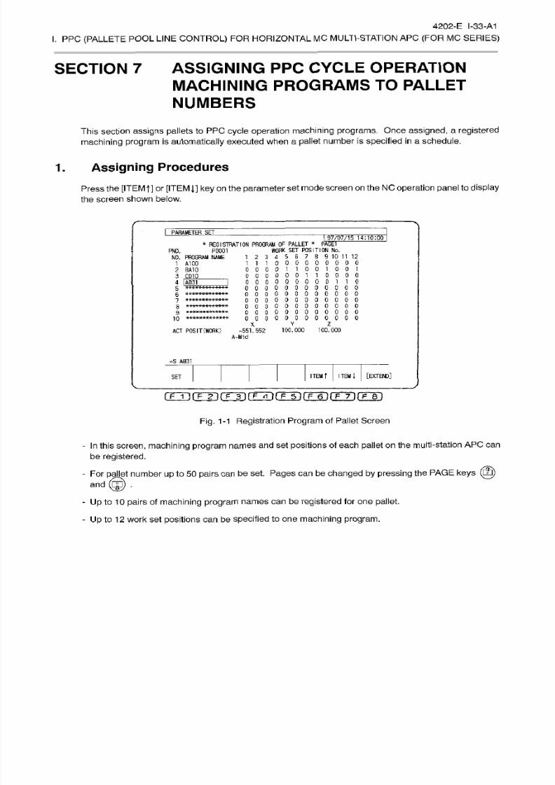
8/15/2019 Okuma Manuals 391
http://slidepdf.com/reader/full/okuma-manuals-391 304/397
4202-E I-33-A1
I.
PPC
(PALLETE
POOL
LINE
CONTROL)
FO R
HORIZONTAL
MC MULTI-STATION
AP C
(FOR
MC
SERIES)
SECTION
7
ASSIGNING
PPC CYCLE
OPERATION
MACHINING PROGRAMS
TO
PALLET
NUMBERS
This section
assigns pallets to PPC
cycle
operation
machining
programs. Once
assigned,
a
registered
machining program
is
automatically
executed
when
a
pallet
number
is
specified
in
a schedule.
1.
Assigning Procedures
Press the
[ITEMf] or
[ITEM],]
ke y
on
the
parameter
set mode
screen on
the
NC operation
panel to
display
the screen
shown below.
I
PARAMETER
~SEf
97/07/15
1
4
:
1
0
:
00
*
REGISTRATION
PROGRAM OF PALLET
«
PAGE
WORK SE T POSITION No.
1
2
3
4
5 6
7
8
9 10 11 12
11100000000
0
00001
1001001
0000001
10000
000000000110
0 0 0
0 0 0
P0001
N0.
NO .
PROGRAM
NAME
1
A100
2 5A10
3
CD10
_
4
IAB31
000000000
0 0
0
0 0 0
7
0 0
000000000000
000000000000
000000000000
ooooooooo
0
0
ACT
POSIT
(WORK)
-551ÿ552
100.000
100.000
A-Mtd
Y
Z
=S AB31
ITEM
t
ITEM
1
[EXTEND]
SET
nÿfÿTT(Tÿ(TÿrFÿrrÿrrrirrei
Fig. 1-1
Registration
Program
of
Pallet Screen
- In
this
screen, machining
program
names
and
set positions of
each pallet on
the
multi-station
AP C can
be
registered.
-
Fo r
pallet
number
up to 50
pairs can
be set. Pages
can
be
changed by
pressing
the PAGE
keys
(SB)
®
•
nd
-
Up
to
10
pairs
of
machining
program
names
can
be
registered
for
on e
pallet
- Up to 12 work
set
positions can
be
specified to
one machining
program.

8/15/2019 Okuma Manuals 391
http://slidepdf.com/reader/full/okuma-manuals-391 305/397
4202-E I-34-A1
I.
PPC
(PALLETE
POOL LINE
CONTROL)
FOR
HORIZONTAL MC
MULTI-STATION APC
(FOR
MC
SERIES)
[Setting
the pallet number]
-
Entry
-
Setting
range
S_
[pallet number] [RETURN]
1 to
9000
Input to clear
al l the
registered
items.
[Setting
the
machining program
name]
-
Entry
S_
[machining
program
name
(set
the
“?????????????”
portion
in
the
“PPC
?????????????.
MIN.”)]
[RETURN]
Up
to 10
pairs
of
machining
program names can
be registered
to on e
pallet.
Up
to 13
characters
(0
to
9/A
to
Z/-).
(The
first character must
be an
alphabet (A
to
Z).)
-
Setting range
“5241
program
name”
Code: None
Cause:
Program
name
setting
was
incorrect.
-
Error
[Setting the work set
position]
SJ
or 0
[Return]
Up
to
12 work
set
positions
can be
specified
to one
machining program.
-
Entry
-
Setting
range
1
orO
Work
set position I Work scl position
2
Work set
position
3
Work set
position
4
Work
A 1
00
Work
None
ork
AI00
Work
A
100
L
Work set position 5
Work
set position
6 Work
set
position
7 Work
scl
position 8
Work BAIO
|
Work CDJ0
ork
BA 10
Work CD10
Work
set
position
9
Work
set position 10
Work
scl position
1 1
Work set
position
12
Work BA 10
ork
BA
10
Work AB31
Work AB 3
1
Fig. 1-2
Work
Set Position
Diagram
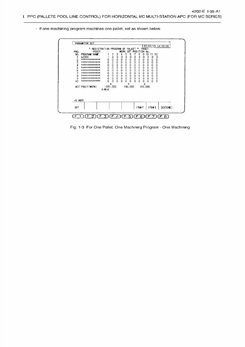
8/15/2019 Okuma Manuals 391
http://slidepdf.com/reader/full/okuma-manuals-391 306/397
4202-E I-35-A1
I.
PPC
(PALLETE
POOL LINE
CONTROL)
FOR HORIZONTAL
MC MULTI-STATION APC
(FOR
MC
SERIES)
-
If one
machining
program
machines
one
pallet, set as shown below.
PARAMETER
SET
I
97/07/15
14:10:00
*
REGISTRATION
PROGRAM OF PALLET
*
PAGE1
WORK SET POSITION No .
1
2 3
4
5
6 7
8
9
10 11
12
1
00000000000
000000000000
0 0 0
0
0
0 0
0
0 0 0 0
oooooooooooo
000000000000
oooooooooooo
oooooooooooo
oooooooooooo
oooooooooooo
oooooooooooo
P0001
NO.
NO.
PROGRAM
NAME
1
A2356
2
3
4
5
6
7
*************
8
?
10
X Y
Z
AC T
POSIT
(WORK
-551.552
100.000
100.000
A-M1d
=S
AB31
ITEM
l
[EXTEND]
TEM
t
ET
Fig.
1-3 For One
Pallet,
One
Machining Program
- One
Machining
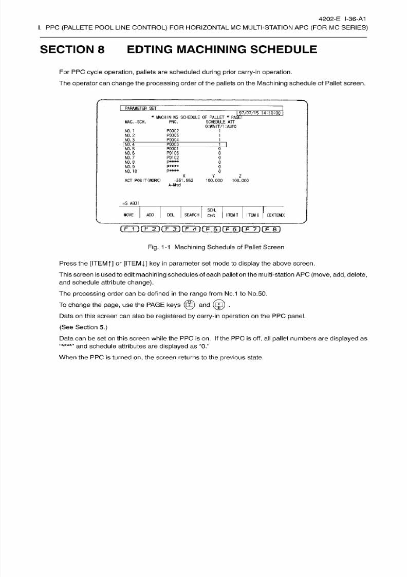
8/15/2019 Okuma Manuals 391
http://slidepdf.com/reader/full/okuma-manuals-391 307/397
4202-E I-36-A1
I.
PPC
(PALLETE
POOL LINE
CONTROL)
FOR HORIZONTAL
MC MULTI-STATION APC
(FOR
MC
SERIES)
SECTION 8 EDTING MACHINING
SCHEDULE
Fo r PPC
cycle
operation, pallets
are
scheduled
during
prior
carry-in
operation.
The
operator
can change the
processing
order of
the
pallets
on
the
Machining
schedule of
Pallet screen.
PARAMETER
SE T
I
97/07/15
*
PAGET
14:10:00
*
MACHINING
SCHEDULE
OF
PALLET
SCHEDULE ATT
0:WAIT/1
:AUT0
MAC.-SCH.
PNO.
NO .
1
P0002
P0005
P0004
1
NO .
2
1
NO . 3
1
NO. 4 P00C3
M
NO . 5
NO .
6
TOOT
P0106
P0102
pit
K
M
K
0
0
NO . 7
0
NO .
8
0
NO . 9 0
NO. 10
0
X
V
z
AC T
POSIT(WORK)
-551.552
100.000
100.000
A-Mtd
=S
AB31
SCH.
ITEM
t
[EXTEND]
OVE
AD D
DEL
SEARCH
ITEM
l
HG
irÿfTÿ(Tÿrÿrr~5)rF~ÿirÿTirFsi
Fig.
1
-1 Machining
Schedule of Pallet Screen
Press
the
[ITEMf]
or [ITEM
J,]
ke y
in parameter
set
mode to
display
the above
screen.
This
screen
is
usedto edit
machining
schedules of
each
pallet on
the
multi-station AP C (move,
add,delete,
and schedule attribute
change).
The
processing
order can be defined
in
the
range
from No.1 to
No.50.
To
change
the
page,
us e the PAGE
keys
(SB)
and
(ÿ)
.
Data
on
this
screen can
also
be
registered by carry-in
operation
on
the PPC
panel.
(See
Section
5.)
Data
can
be set
on
this
screen while
the
PPC is on. If
the
PPC is
off, al l
pallet
numbers
are
displayed
as
and schedule attributes
are
displayed
as
“0.”
When
the
PP C
is
turned
on,
the
screen
returns to
the
previous
state.
“****”

8/15/2019 Okuma Manuals 391
http://slidepdf.com/reader/full/okuma-manuals-391 308/397
4202-E I-37-A1
I.
PPC
(PALLETE
POOL LINE
CONTROL)
FOR HORIZONTAL
MC MULTI-STATION APC
(FOR
MC
SERIES)
(1)
Moving Machining Schedules
- The
operator
can move the
processing
order of
machining
schedules.
-
Move the
cursor to
a
line
containing
the
pallet whose
machining
schedule
is
to be
moved,
press
the
[MOVE] function
key.
Enter a required
processing
order
and
press [RETURN], The pallet number
moves
to
the line selected
for
the
new processing
order.
The schedule attribute
also moves accordingly
and the tab le
is
updated.
Moving
procedures
. . .
MV_[processing
order]
[RETURN]
Moving range
1
to
maximum stat ion
number
If
the
pallet
with
processing
order
1
is
in
process
on the
machine,
it cannot
be
moved to
processing
order
1.
If
a pallet
sharply
exceeds the
present
processing
order even if it
does
not
exceeds the
maximum station number, it
is
added after
the
maximum processing
order
set
at
present
and
no
blank
processing orders
are
generated.
“5286
Set condition error
Code
:1
The pallet
at
the
source cursor position
is
not
ready
for
machining.
(The
pallet
number at the source
cursor
position is
not
found.)
:2
Th e
same
pallet number
is
specified
as
the
source and
destination.
Error
:3
Th e
destination
pallet
is not
ready
for
processing.
(The pallet
number
at
the
destination
cursor
position
is not
found.)
(2)
Adding Machining
Schedules
-
Machining
schedules can be added.
-
Move
the
cursor
to
a
line to which
a
machining
schedule is
to
be added
and
press
the
[ADD]
function
key.
Enter a
new
pallet
number
and
press [RETURN],
The
entered
pallet
number is
added
using
the
schedule attribute of
the
source l ine and the table is
updated.
Adding
procedure
NSJpallet
number]
[RETURN]
Addition
range
1
to maximum station number
Machining
schedules
can
be added
for
only
pallets
registered in
the
pallet
station
number/pallet number table.
“5286 Set condition error
Code
:
1 The pallet at the source cursor position is not
ready
for
machining.
(The pallet number at
the source
cursor position is not found.)
:2 The pallet number to be added
is
not found.
:3 The operator attempted to
add
a pallet number not
registered
in
the
pallet
station
number/pallet
number table.
A
The
operator attempted
to
add
a
pallet
number
whose
processing
number
is
already
set.
Error

8/15/2019 Okuma Manuals 391
http://slidepdf.com/reader/full/okuma-manuals-391 309/397
4202-E I-38-A1
I.
PPC
(PALLETE
POOL LINE
CONTROL)
FOR HORIZONTAL
MC MULTI-STATION APC
(FOR
MC
SERIES)
(3)
Searching for Machining
Schedules
- The
operator
can search the
processing
order of
machining
schedules and move them with the cursor.
- Press
the
[SEARCH] function and
enter a
processing
order to be searched.
The
cursor moves
to
the
line
containing
the entered
processing
order.
Search procedure
....
FJprocessing
order] [RETURN]
Search range
Error
1
to
maximum
processing
order registered
‘‘5286
Set
condition error’’
Code
:1
The pallet at the source
cursor position
is not
ready
for
machining.
(The pallet
number at the
source cursor
position
is
not
found.)
(4)
Deleting Machining
Schedules
-
Machining
schedules can be deleted.
- Move
the
cursor to a
line from
which
the
machining
schedule is to be
deleted and press
the
[DEL]
function.
The
line selected
with
the
cursor
is
deleted and
the
table
is
updated.
Delete
procedures
____
EL
[RETURN]
Delete range 1
to maximum
processing
order
registered
If the pallet with
processing
order 1 is
in
process on the
machine,
it cannot be
deleted.
“5286
Set
condition error’’
Code :
1
The
pallet
at the
source
cursor
position
is not ready for
machining.
(The
pallet number at the source cursor
position
is
not found.)
Error
(5)
Changing the Schedule
Attribute
-
The schedule attribute
can
be selected from wait or automatic. The
default
is wait
operation
“0.”
-
Move the
cursor to the
processing
order whose
schedule
attribute is to be
changed
and
press
the
[SCH.
CHG]
function. When the schedule
attribute
is “0,”
it changes
to “1”; an d
when
“1,”
it changes
to “0.”
Change
procedures
. .
SCH
[RETURN]
Change range 0
or
1
Fo r the
pallet
to be
machined
by
wait
operation,
enter “0.”
For the
pallet to
be
machined
by
automatic operation, enter
“1 .’’
Changing
SCHEDULE
ATT
from
“0”
(WAIT)
to
“1”
(AUTO),
the
processing
order
moves after
the last
pallet with
SCHEDULE
ATT
of
“1”
(AUTO).
Changing SCHEDULE ATT from
“1”
(AUTO)
to “0”
(WAIT),
the processing
order
moves
after
the last pallet with SCHEDULE
ATT
of
“0” (WAIT).
“5286
Set condition error’’
Code
:1
The
pallet
at the
source cursor
position
is no t
ready
for
machining.
(The
pallet
number at the
source cursor
position
is
not
found.)
Error
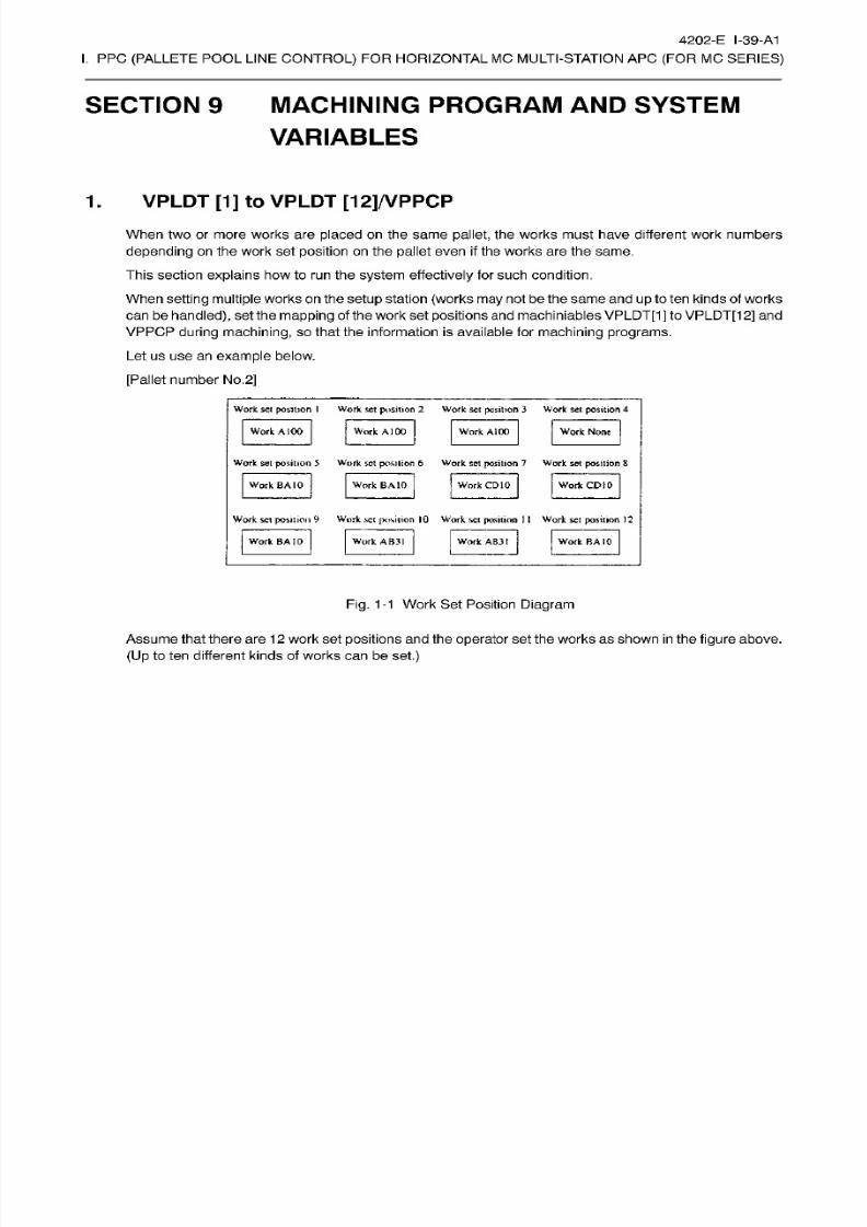
8/15/2019 Okuma Manuals 391
http://slidepdf.com/reader/full/okuma-manuals-391 310/397
4202-E I-39-A1
I.
PPC
(PALLETE
POOL LINE
CONTROL)
FOR HORIZONTAL
MC MULTI-STATION APC
(FOR
MC
SERIES)
SECTION 9 MACHINING
PROGRAM AND
SYSTEM
VARIABLES
1
.
VPLDT [1
]
to
VPLDT [12]/VPPCP
When two or
more
works are
placed
on
the
same
pallet,
the works
must
have
different
work numbers
depending
on the work
set position
on
the pallet
even
if
the works are the same.
This section
explains
howto run
the
system
effectively
for such condit ion.
When
setting
multiple
works
on
the setup
station
(works
may
not be
the same
and
up
to tenkinds of
works
can
be
handled),
set
the
mapping
of the
work set
positions
an d
machiniables VPLDT[1]
to
VPLDT[1
2] and
VPPCP
during machining,
so that the
information
is
available
for
machining programs.
Le t us u se a n
example
below.
[Pallet
number
No .
2]
Work sc i
position
I
Work set
position
2
Work se t position
3
Work
set position
4
Work A 100 Work
A)
00
Work None
ork
A100
Work set position
5
Work set position
6
Work set position 7 Work set posit ion 8
Work
CD
10ork
BA
10
Work
BA
10 Work CD10
Work set position 9
Work
set
position 10
Work
set position
1
1
Work set
position
12
Work
AB31
ork BA
10 Work
AB31
Work BA
10
Fig.
1-1
Work
Set Position
Diagram
Assumethat there are
12
work set
positions
and the
operator
set
the
works
as
shown
in
the
figure
above.
(U p
to ten
different
kinds
of works
can
be
set.)
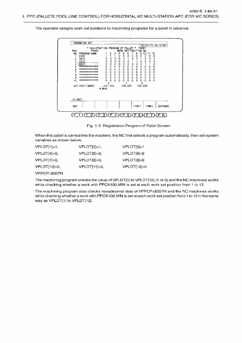
8/15/2019 Okuma Manuals 391
http://slidepdf.com/reader/full/okuma-manuals-391 311/397
4202-E I-40-A1
I.
PPC
(PALLETE
POOL LINE
CONTROL)
FOR HORIZONTAL
MC MULTI-STATION APC
(FOR
MC
SERIES)
The
operator assigns
work set positions to
machining programs
for a pallet
in
advance.
PARAMETER
SE T
97/07/15
14:10:00
*
REGISTRATION PROGRAM
OF
PALLET
*
PAGE1
P0002 WORK
SET
POSITION
No.
1
2
3
4
5
6
7
8 9 10
11
12
111000000000
000011001001
0000001
10000
0000000001
1 0
000000000000
0 0 0 0 0 0 0 0
0
0 0 0
000000000000
000000000000
0 0 0 0 0 0 0 0 0 0 0 0
000000000000
PNO.
NO . PROGRAM
NAME
1
A100
2 BA10
3 CD10
_
4
[AB31
5
6
8
9
10
X
Y
Z
ACT
POSIT(WORK)
-551.552
100.000
100.000
A-Mtd
=S AB31
[EXTEND]
TEM
ITEM
4
ET
Fig.
1-2 Registration Program
of Pallet Screen
When
this
pallet
is carr ied into
the
machine,
the
NC
first
selects
a
program automatically,
then set
system
variables
as
shown
below.
VPLDT[1]=1,
VPLDT[4]=0,
VPLDT[7]=0,
VPLDT[10]=0,
VPPCP=$007H
VPLDT[2]=1
,
VPLDT[5]=0,
VPLDT[8]=0,
VPLDT[11]=0,
VPLDT[3]=1
VPLDT[6]=0
VPLDT[9]=0
VPLDT[12]=0
The machining program
checks
the
value of
VPLDT[1]
to
VPLDT[12]
(1 orO) and
the NC
machines works
while
checking
whether a work with PPCA100.MIN is
set at
each work set position from
1
to
12.
The
machining
program
also
checks hexadecimal data of
VPPCP=$007H
and
the
NC machines
works
while
checking
whether
a
work
with
PPCA100.MIN
is set
at
each
work
set position from
1
to
12 in
the
same
way as VPLDT[1] to VPLDT[12],

8/15/2019 Okuma Manuals 391
http://slidepdf.com/reader/full/okuma-manuals-391 312/397
4202-E
I-41-A1
I.
PPC
(PALLETE
POOL LINE
CONTROL)
FOR HORIZONTAL
MC MULTI-STATION APC
(FOR
MC
SERIES)
The figure below is
an
example
machining
program for
PPCA100.MIN.
(When VPLDT[1] to VPLDT[12] are used)
OAIOO
N001
IF
VPLDT
[
1
J
EQ
0]N002
G15H1
CALL OSUB1
N002 IF
[VPLDT [
2
]
EQ
0]K003
G15H2
CALL
OSUB1
N003
IF
[VPLDT
[3 ]
EQ
0]N004
G15H2
CALL OSUB1
Fig. 1-3
Machining Program
Example
1
Write
the
actual
machining
program
in
OSUB1 and write the main program to check whether
a
work
is set
in
each work set
position
and if the work
is set,
selects its coordinates.
After
PPCA100.MIN
completes,
the NC
automatically
selects
PPCBA10.MIN.
System
variables are
set
as shown
below.
VPLDT[2]=0,
VPLDT[5]=1,
VPLDT[8]=0,
VPLDT[11]=0,
VPLDT[1]=0,
VPLDT[4]=0,
VPLDT[7]=0,
VPLDT[10]=0,
VPPCP=$930H
The
process
after
this
is
the sam e as
for
PPCA100.MIN.
VPLDT[3]=0
VPLDT[6]=1
VPLDT[9]=1
VPLDT[12]=1

8/15/2019 Okuma Manuals 391
http://slidepdf.com/reader/full/okuma-manuals-391 313/397
4202-E
I-42-A1
I.
PPC
(PALLETE
POOL LINE
CONTROL)
FOR HORIZONTAL
MC MULTI-STATION APC
(FOR
MC
SERIES)
2.
VPLNO
-
VPLNO indicates
the number
of
the
pallet
located
on
the machine table
at
present.
-
Use VPLNO to
change
the work coordinate
system
for each
pallet
when the
same
work is
placed
on
multiple pallets
or
a
different
origin
offset
is
used
for
each
pallet.
(Example)
Fo r
machining
works on
pallets 0001
and
0002,
us e work
coordinate
system
11
for the No.1
pallet
and
work
coordinate
system
12
for the
No.2
pallet.
oiooo
N001
IF
(VPLNO
EQ
1]N010
IF
(VPLNO
EQ
2
]
N020
GOTO NEND
N010
G15
HI
1
GOTO N100
N020 G15
H12
GOTO
N100
N100
[actual
machining
process]
NEND M0 2
Fig.
1-4
Machining Program
Example
3
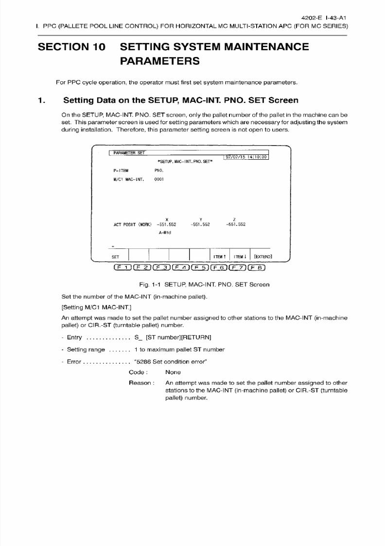
8/15/2019 Okuma Manuals 391
http://slidepdf.com/reader/full/okuma-manuals-391 314/397
4202-E I-43-A1
I.
PPC
(PALLETE
POOL LINE
CONTROL)
FOR HORIZONTAL
MC MULTI-STATION APC
(FOR
MC
SERIES)
SECTION 10 SETTING SYSTEM
MAINTENANCE
PARAMETERS
For PPC
cycle
operation,
the
operator
must
first
set
system
maintenance
parameters.
1. Setting
Data on the
SETUP,
MAC-INT.
PNO.
SET
Screen
On
the
SETUP,
MAC-INT
PNO.
SE T
screen,
only the
pallet
number of the
pallet
in the machine
can
be
set. This
parameter
screen is
used
for
setting
parameters
which
are necessary fo r adjusting
the
system
during
installation.
Therefore,
this
parameter
setting screen
is
not
open
to users.
PARAMETER
SET
97/07/15
14:10:00
MAC-
1
NT.
PNO. SET*
P-ITEM
PNO.
M/C1
MAC-INT.
0001
X
Y
Z
ACT
POSIT
(WORK)
-551.552
A-Mtd
-551.552
-551.552
[EXTEND]
TEM
t
ITEM]
ET
o
i
) (Fÿrÿ(Tÿ(TT)r r6 i rF-T)rF~r)
Fig. 1-1 SETUP,
MAC-INT. PNO.
SET Screen
Set
the number
of
the MAC-INT
(in-machine
pallet).
[Setting
M/C1
MAC-INT.]
An
attempt
was
made to set
the
pallet
number
assigned
to
other stations
to the
MAC-INT
(in-machine
pallet)
or
CIR.-ST
(turntable pallet)
number.
S_
[ST
number][RETURN]
Entry
-
Setting
range
. 1
to maximum
pallet ST number
.
“5286
Set
condition error”
Code
:
None
Reason
: An
attempt
was made to set
the
pallet
number
assigned
to other
stations to the MAC-INT
(in-machine pallet)
or CIR.-ST
(turntable
pallet)
number.
-
Error

8/15/2019 Okuma Manuals 391
http://slidepdf.com/reader/full/okuma-manuals-391 315/397
4202-E
I-44-A1
I.
PPC
(PALLETE
POOL LINE
CONTROL)
FOR HORIZONTAL
MC MULTI-STATION APC
(FOR
MC
SERIES)
2.
Setting
Data
on
the
PALLET
CARRIER
NO.-PALLET
NO.
TABLE
Screen
I
PARAMETER SE T
97/07/15
14:10:00
ABLE*
PALLET
CARRIER
NO .
-PALLET
NO .
T.
RAGE1
CL-NO. PNO.
P0001
P0002
P0003
P0004
P0005
5 P0006
6 P0007
P0008
8
P
NONE
P
NONE
CL-NO. PNO.
10
P NONE
P
NONE
P NONE
13
P
NONE
14
P NONE
15
P
NONE
16 P NONE
17
P
NONE
P
NONE
19
P
NONE
MC-NO.
PNO.S1
1 00011
1
12
3
4
7
18
9
X
Z
AC T
POSIT
(WORK)
-551.552
-551.552
-551.552
A-Mtd
[EXTEND]
TEM
T
ITEM
i
ET
rF~Tl
(T~F)
fF~1T)
fF~6~)
(~F~7ÿ (T~1T)
Fig.
1-2
PALLET
CARRIER NO.-PALLET NO.
TABLE
Screen
This
screen is used to set
pallet
numbers
for
each
pallet
carrier on
the multi-station
APC.
The data restrictions follow the multi-station APC
specification
and
the
pallet
number must
not
exceed
the maximum number of
pallet
stations.
(1) Setting
the
Pallet
Number
Setting
procedures
. .
S_
[pallet number] [RETURN]
Setting
range
0
to
maximum
station number
When “0”
is
entered,
“None”
is
displayed.
“5285 Set condition error”
Code
:1
An
attempt
was made tost a
pallet
to
the
station
exceeding
the
maximum
station
number.
:2
An
attempt
was
made
to
register
a
pallet
number already
registered.
(2)
Displaying
the MC No.
-pallet
Number Table
The screen displays the
pallet
number of the
pallet
in the machine.
Error
(3)
Displaying
the Attribute of the
Setup
Station
Pallet
Attributes MS 1
and
WS1 are
displayed
to
the
side of
the
machine’s
standby
station number
and
the
setup
station
number,
respectively, which
are set
at
the
PALLET
CARRIER NO.
-PALLET
NO .
TABLE
screen. This
facilitates checking
of thestation
position
of the machine’s
standby
station
and
the
setup
station.

8/15/2019 Okuma Manuals 391
http://slidepdf.com/reader/full/okuma-manuals-391 316/397
4202-E I-45-A1
I.
PPC
(PALLETE
POOL LINE
CONTROL)
FOR HORIZONTAL
MC MULTI-STATION APC
(FOR
MC
SERIES)
3. Communication Interface between the Touch Panel and NC
(RS232C
Communication
Parameters)
(1)
Baud Rate:
2400,
4800,
9600,
19200
bps
(2)
Data
Bit Length:
(3) Stop
Bit:
(4)
Parity Bit:
(5)
Flow
Control:
7
or
8
bits
1
or
2 bits
Even,
odd,
none
RS/CS
control,
XON/XOFF
control,
none
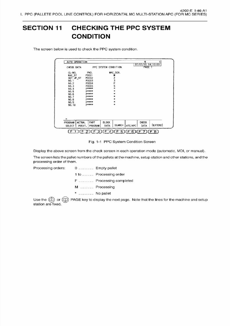
8/15/2019 Okuma Manuals 391
http://slidepdf.com/reader/full/okuma-manuals-391 317/397
4202-E I-46-A1
I.
PPC
(PALLETE POOL
LINE
CONTROL)
FOR HORIZONTAL MC
MULTI-STATION
APC
(FOR
MC
SERIES)
SECTION 11
CHECKING THE
PPC
SYSTEM
CONDITION
The
screen
below
is
used
to
check the PPC
system
condition.
I
AUTO
OPERATION
N
1
97/07/15
14:10:00
CHECK
DATA
PPC SYSTEM CONDITION
CL-NO.
MAC_ST
P0001
SE T
UP
ST P0002
P0003
P0004
P0005
p***»
p****
p***»
p***»
p»***
p****
p****
PNO.
MAC SCH.
U
2
3
O.
1
NO.
2
F
5
O. 3
NO. 4
*
O. 5
*
O. 6
*
O.
7
*
O.
8
*
O. 9
*
O. 10
CHECK
ROGRAM ACTUAL
PART
SELECT
POSIT.
PROGRAM
BLOCK
[EXTEND]
EARCH
ATC/APC
AT A
DATA
nrrifÿinrrT)[TTÿrFir)rFinrrT)iTin
Fig.
1-1
PPC
System
Condition Screen
Display the
above
screen
from
the check
screen in
each
operation
mode
(automatic,
MDI, or
manual).
The screen lists the pallet numbers of the
pallets
at the
machine,
setup station and other
stations,
an d the
processing
order of them.
Processing
orders: 0
Empty
pallet
Processing
order
Processing completed
Processing
No pallet
Use
the
(0)
or
(Eg)
PAGE
key to
display
the next
page.
Note that the lines
for
the machine and
setup
station
are
fixed.
1 to
F
M
*
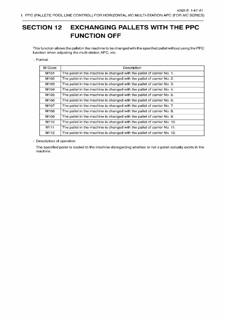
8/15/2019 Okuma Manuals 391
http://slidepdf.com/reader/full/okuma-manuals-391 318/397
4202-E
I-47-A1
I.
PPC
(PALLETE
POOL LINE
CONTROL)
FOR HORIZONTAL
MC MULTI-STATION APC
(FOR
MC
SERIES)
SECTION 12 EXCHANGING PALLETS
WITH
THE PPC
FUNCTION
OFF
This fu
notion
allows
the
pallet
i
n
the mach
ine
to
be
changed
with the
specified pallet
without
using
the
PPC
function when
adjusting
the multi-station
APC,
etc.
-
Format
M
Code
Description
M101
The
pallet
in the machine
is
changed
with the
pallet
of carrier No.
1.
M102 The pallet in the machine is changed
with
the pallet of
carrier No.
2.
M103
The
pallet
in the machine
is changed
with the
pallet
of
carrier
No.
3.
M104
The
pallet in
the machine is
changed
with the
pallet
of
carrier
No.
4.
M105 The
pallet in the machine
is
changed
with the
pallet
of carrier No. 5.
M106
The
pallet
in the machine
is changed
with
the
pallet
of
carrier
No.
6.
M107
The
pallet in
the machine
is changed
with the
pallet
of
carrier No. 7.
M108 The
pallet in
the
machine
is
changed
with the
pallet
of carrier No. 8.
M109 The
pallet
in the machine
is changed
with
the
pallet of
carrier No. 9.
M110
The
pallet in
the
machine is
changed
with the
pallet
of
carrier No.
10.
M1
11
Th e pallet in
the machine is
changed
with the
pallet
of carrier No.
11 .
M112
The
pallet
in the machine is
changed
with
the
pallet of
carrier No.
12.
-
Description of operation
The
specified
pallet
is
loaded
to
the machine
disregarding
whether
or
not
a
pallet
actually
exists
in the
machine.
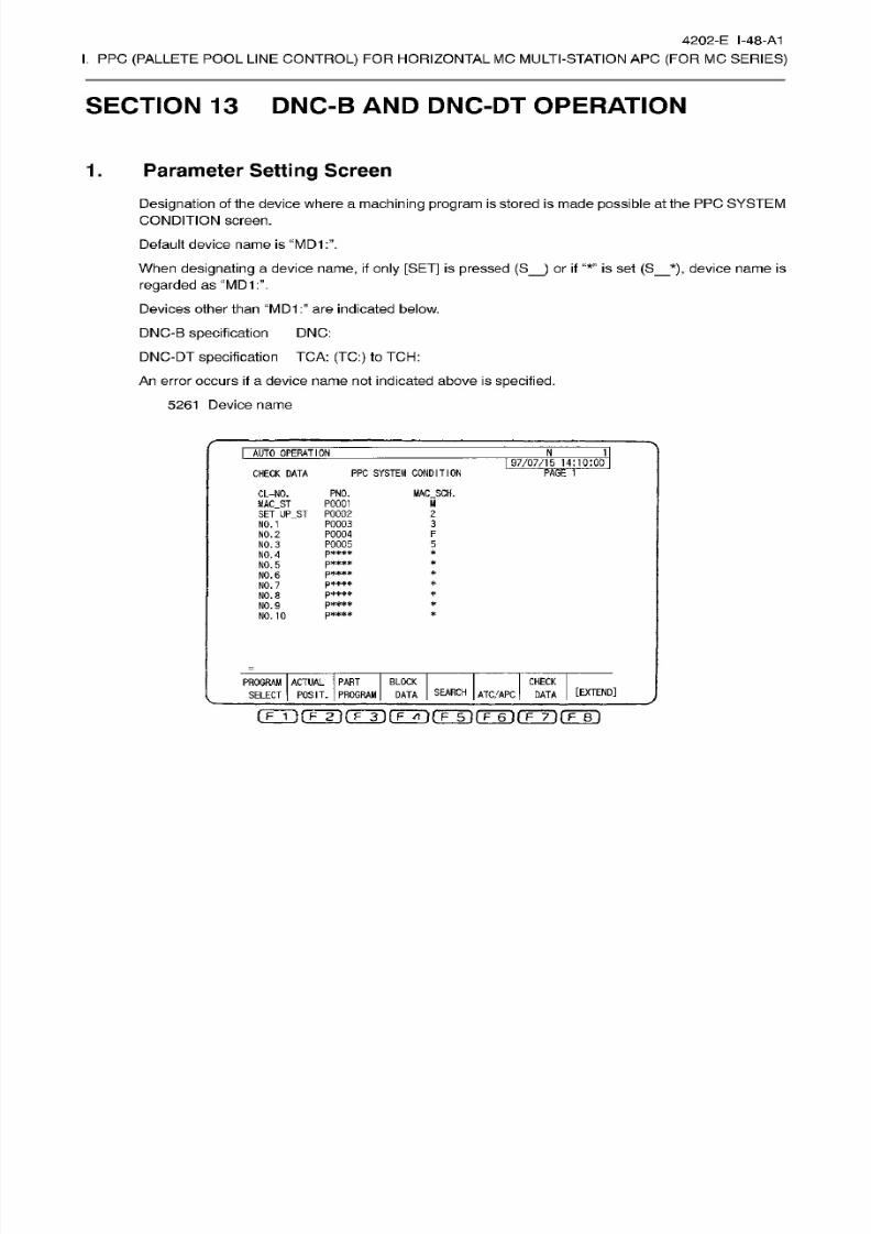
8/15/2019 Okuma Manuals 391
http://slidepdf.com/reader/full/okuma-manuals-391 319/397
4202-E I-48-A1
I.
PPC
(PALLETE
POOL LINE
CONTROL)
FOR HORIZONTAL
MC MULTI-STATION APC
(FOR
MC
SERIES)
SECTION 13 DNC-B AND DNC-DT OPERATION
Parameter Setting
Screen.
Designation
of
the
device
where
a
machining
program is stored
is made
possible
at the
PPC
SYSTEM
CONDITION
screen.
Default device name
is
When
designating
a device
name, if only
[SET]
is pressed
(S_)
or
if
“*”
is set
(S_*),
device
name is
regarded
as “MD1:”.
Devices other
than “MD1 are
indicated
below.
DNC-B
specification
DNC:
DNC-DT
specification
TCA:
(TC:)
to TCH:
An
error
occurs
if
a
device
name
not indicated
above
is
specified.
5261
Device
name
I
AUTO
OPERAT ION
J
1
97/07/15
14:10:00
PPC SYSTEM
CONDITION
HECK DATA
PAGE
1
CL-NO.
MAC_ST
SET
JP_ST
PNO. MAC
SCH.
M
0001
P0002
P0003
90004
P0005
p****
p***»
p****
p****
p*#**
p«***
2
3
O.
1
F
O.
2
5
O.
3
*
O.
A
*
O.
5
*
O.
6
*
O.
7
*
O.
8
*
O.
9
*
O. 10
CHECK
ROGRAM
ACTUAL
PART
SELECT POSIT.
PROGRAM
BLOCK
[EXTEND]
EARCH
ATC/APC
DATA
AT A
(? T1
fp~F)
fT~rn fF~in
(T~el
(T~7H(TTBI
8/15/2019 Okuma Manuals 391
http://slidepdf.com/reader/full/okuma-manuals-391 320/397
4202-E I-49-A1
I.
PPC
(PALLETE
POOL LINE
CONTROL)
FOR HORIZONTAL
MC MULTI-STATION APC
(FOR
MC
SERIES)
2.
DNC-B
Operation
from the
PPC
-
PPC mode ON
By the
PPC
cycle
start
operation,
machining programs registered by
pallets
are
selected and executed
according
to the machining
schedule
by
pallets.
(If
the
PPCmode
switch
is
in
the
“Continuous”
position,
machining
is
performed
continuously
for
multiple
pallets, and
if
it is
in
the
“One
cycle”
position,
the
program
is
executed
only
for
one
pallet.)
In
the
state the DNC-B
operation
is not
possible
(DNC-B operation
not
ON,
buffer
operation not
ON), if
the device
of the
machining program to
be
selected
and executed
is
“DNC:”, an alarm
occurs.
2375 Alarm
B No
user
program
1
8000000
The following
alarm
occurs if
the
machining
program
to be
selected is
not
in
the specified device at
the
cycle
start of
PPC.
2375
Alarm B
No user
program
10000002
If
the
setting
for communication
parameter
“N C
program
transfer
method”
is “A ”
(no
file nam e
designation),
the
alarm
indicated below occurs and
the
machining
program
in
device
“DNC:”
is
neither
selected nor executed.
2375
Alarm B No
user
program
1
8000000
Execution
of a
program
by normal program selection and
NC
cycle
start
is not
possible.
If this
is
attempted,
the
following
alarm
occurs
at
the
cycle
start
of
the
NC.
4282 Alarm
B
PP C
cycle
can’t start
If
the
NC is reset
during
DNC-B mode
operation,
cycle
start of the NC starts communication
again
and
the
registered
program
is selected and executed.
-
PPC mode OFF
The program
selected
at
the
PPC SYSTEM CONDITION
screen is
not
selected and executed by
the
PPC
cycle
start
operation.
The program selected in normal
program
selection
operation
is executed
by
the
cycle
start of
the
NC.
8/15/2019 Okuma Manuals 391
http://slidepdf.com/reader/full/okuma-manuals-391 321/397
4202-E I-50-A1
I.
PPC
(PALLETE
POOL LINE
CONTROL)
FOR HORIZONTAL
MC MULTI-STATION APC
(FOR
MC
SERIES)
3. DNC-DT
Operation
from
the
PPC
-
PPC mode ON
By the
PPC
cycle
start
operation,
machining programs registered by
pallets
are
selected and executed
according
to the machining
schedule
by
pallets.
(If
the
PPCmode
switch is
in
the
“Continuous”
position,
machining
is
performed
continuously
for
multiple
pallets, and
if
it
is
in
the
“One
cycle”
position, the program is
executed
only
for
one
pallet.)
In
the
state the DNC-DT operation
is
not
possible
(TCP/IP communication
not
ON), if the device of the
machining program
to be selected and
executed is
“TCA:
(TC:)
-
TCH:”,
an
alarm
occurs.
2375
Alarm B No
user
program
1
8000000
The following
alarm
occurs if
the
machining
program
to be
selected is
not
in
the specified device at
the
cycle
start of
PPC.
2375
Alarm B
No user
program
10000002
(if
device
name
is
MD1
:)
2531
Alarm
B
DNC-DT
Program select
80000084
(if device
name
is TCA:
(TC:)
-
TCH:)
Execution of
a
program by normal program selection
an d NC
cycle
start is not
possible.
If
this is
attempted,
the following
alarm
occurs at
the
cycle
start of
the
NC.
4282
Alarm
B
PPC
cycle
can’t
start
-
PPC mode OFF
The
program
selected
at the
PP C
SYSTEM CONDITION screen is
not
selected and executed
by
the
PPC
cycle
start
operation.
The program selected in
normal
program selection
operation
is executed by
the cycle
start of
the NC.
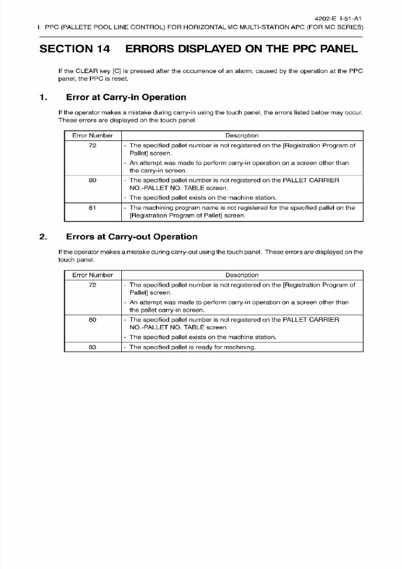
8/15/2019 Okuma Manuals 391
http://slidepdf.com/reader/full/okuma-manuals-391 322/397
4202-E
1-51
-A1
I.
PPC
(PALLETE
POOL LINE
CONTROL)
FOR HORIZONTAL
MC MULTI-STATION APC
(FOR
MC
SERIES)
SECTION
14
ERRORS DISPLAYED
ON THE
PPC
PANEL
If the CLEAR key
[C]
is
pressed
after the occurrence
of
an
alarm,
caused by the
operation
at
the
PPC
panel,
the PPC is reset.
1.
Error
at Carry-in
Operation
If
the
operator
makes
a
mistake
during
carry-in
using
the
touch
panel, the
errors
listed
below
may occur.
These
errors
are
displayed
on
the touch panel.
Error Number Description
-
The
specified pallet
number
is
not
registered
on
the
[Registration Program
of
Pallet]
screen.
-
An
attempt
wa s
made to
perform
carry-in
operation
on
a
screen
other
than
the
carry-in
screen.
72
-
The specified pallet number
is
not
registered
on the
PALLET CARRIER
NO.-PALLET NO.
TABLE
screen.
80
-
The specified pallet exists
on the
machine station.
- The machining program name
is not
registered
fo r the
specified pallet
on the
[Registration
Program
of Pallet] screen.
81
2.
Errors
at Carry-out
Operation
If
the
operator
makes amistake during
carry-out
using the touch panel. These
errors are
displayed
on
the
touch
panel.
Error Number Description
-
The
specified pallet
number
is
not
registered
on
the
[Registration Program
of
Pallet]
screen.
-
An
attempt
was made to
perform
carry-in
operation
on
a
screen other
than
the
pallet
carry-in
screen.
72
-
The
specified pallet
number
is
not registered
on
the PALLET
CARRIER
NO.-PALLET NO.
TABLE
screen.
-
The
specified pallet
exists
on the
machine station.
80
-
The
specified pallet
is
ready
for machining.
3
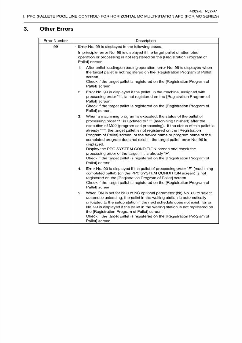
8/15/2019 Okuma Manuals 391
http://slidepdf.com/reader/full/okuma-manuals-391 323/397
4202-E I-52-A1
I.
PPC
(PALLETE
POOL LINE
CONTROL)
FOR HORIZONTAL
MC MULTI-STATION APC
(FOR
MC
SERIES)
3. Other
Errors
Error Number
Description
-
Error
No. 99 is displayed in the following cases.
In
principle, error
No.
99
is
displayed
if
the
target
pallet of attempted
operation
or
processing is
not
registered
on the
[Registration Program
of
Pallet]
screen.
1 .
After
pallet
loading/unloading
operation, error
No .
99 is
displayed
when
the
target
pallet
is not
registered on the [Registration Program
of
Pallet]
screen.
Check if the
target pallet
is
registered
on
the
[Registration Program
of
Pallet]
screen.
2.
Error
No.
99
is
displayed if
the
pallet, in
the
machine,
assigned
with
processing
order
“1”,
is
not
registered
on
the
[Registration Program
of
Pallet]
screen.
Check if the
target
pallet
is registered
on
the [Registration
Program
of
Pallet]
screen.
3.
When a
machining program
is
executed,
the
status
of the
pallet
of
processing
order “1 ” is
updated
to
“F” (machining
finished)
after the
execution of
M02
(program end
processing).
If
the status of
this
pallet
is
already “F”,
the target
pallet
is not
registered
on
the [Registration
Program
of
Pallet]
screen, or the device
name
or program
name
of the
completed
program
does
not
exist
in
the
target
pallet, error No. 99
is
displayed.
Display the
PPC SYSTEM CONDITION screen and check the
processing
order of the
target
if it
is
already
“F”.
Check
if
the
target
pallet
is
registered on
the
[Registration Program of
Pallet]
screen.
4.
Error
No.
99 is
displayed if
the pallet
of
processing
order
“F
(machining
completed
pallet)
(on
the PP C
SYSTEM
CONDITION
screen)
is
not
registered on the
[Registration Program
of
Pallet]
screen.
Check
if
the
target
pallet
is
registered
on the
[Registration Program
of
Pallet] screen.
5.
When ON is
set
for bit 0
of NC
optional parameter (bit)
No.
63
to select
automatic
unloading,
the
pallet
in
the
waiting
station is
automatically
unloaded to the
setup
station
if
the
next
schedule does
not
exist. Error
No. 99 is
displayed if
the pallet
in
the
waiting
station is not
registered
on
the
[Registration Program
of
Pallet]
screen.
Check
if the
target pallet
is registered
on
the
[Registration
Program
of
Pallet]
screen.
99
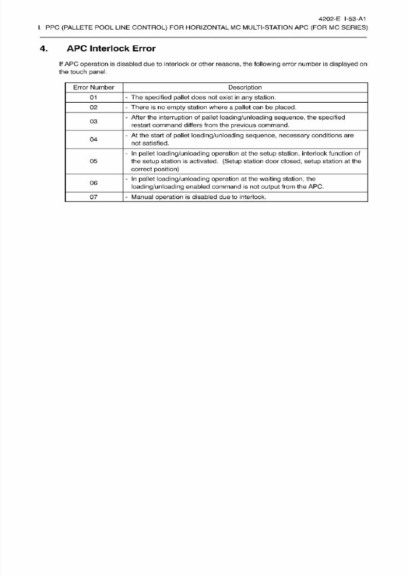
8/15/2019 Okuma Manuals 391
http://slidepdf.com/reader/full/okuma-manuals-391 324/397
4202-E I-53-A1
I.
PPC
(PALLETE
POOL LINE
CONTROL)
FOR HORIZONTAL
MC MULTI-STATION APC
(FOR
MC
SERIES)
4.
APC
Interlock
Error
If
APC
operation
is
disabled due to interlock
or other
reasons,
the
following
error number
is
displayed
on
the touch
panel.
Error Number
Description
-
The
specified pallet
does
not
exist in
any
station.
1
02
-
There is
no
empty station where a pallet can be placed.
-
After the
interruption
of
pallet
loading/unloading sequence, the specified
restart command
differs
f rom the
previous
command.
3
-
At the
start of
pallet
loading/unloading
sequence,
necessary
conditions
are
not
satisfied.
4
-
In
pallet
loading/unloading
operation
at the
setup
station,
interlock function
of
the
setup
stat ion is activated.
(Setup
station
door
closed,
setup
station at the
correct
position)
05
-
In
pallet
loading/unloading
operation
at
the
waiting
station,
the
loading/unloading
enabled command is
not
output
from
the
APC.
6
-
Manual operat ion is
disabled
due to
interlock.
7
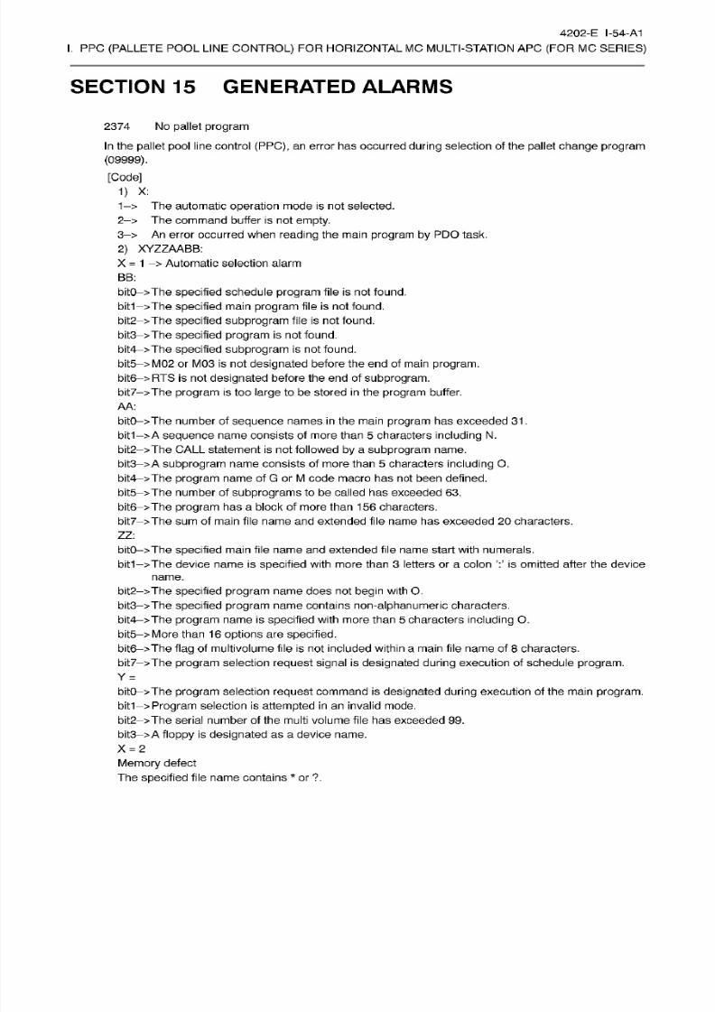
8/15/2019 Okuma Manuals 391
http://slidepdf.com/reader/full/okuma-manuals-391 325/397
4202-E I-54-A1
I.
PPC
(PALLETE
POOL LINE
CONTROL)
FOR HORIZONTAL
MC MULTI-STATION APC
(FOR
MC
SERIES)
SECTION
15
GENERATED ALARMS
2374
No
pallet
program
In
the
pallet pool
line
control
(PPC),
an
error
has
occurred
during
selection of the
pallet
change program
(09999).
[Code]
1) X:
1->
The automatic
operation
mode
is
not selected.
2->
The command
buffer is not empty.
3->
An
error
occurred when
reading
the
main
program by
PD O
task.
2)
XYZZAABB:
X
=
1
>
Automatic
selection
alarm
BB:
bitO->The specified
schedule
program
file is not found.
bit1->The
specified
main
program
file
is
not found.
bit2->The
specified
subprogram
file is not
found.
bit3->The specified
program
is not found.
bit4->The
specified
subprogram
is not
found.
bit5->M02
or M03 is not
designated
before
the
end of
main program.
bit6->RTS
is
not
designated
before the end of
subprogram.
bit7->The
program is
too
large
to be
stored in the program
buffer.
AA :
bitO->The
number of
sequence names
in
the main program has exceeded 31.
bit1—
>A
sequence name consists of more than 5
characters including
N.
bit2 >The
CALL
statement
is not
followed by
a
subprogram
name.
bit3
>
A
subprogram
name
consists
of
more
than
5
characters
including
0.
bit4->The
program
name of G or
M
code
macro
ha s not been defined.
bit5->The number
of
subprograms
to be called has exceeded 63.
bit6ÿ>The
program has
a b lock o f more
than 156 characters.
bit7 >The
sum
of main file name
and extended
file
name has
exceeded 20
characters.
ZZ :
bitO->The
specified
main file
name
and extended file
name start
with numerals.
The device
name
is
specified
with more
than
3
letters or a colon is omitted
after
the device
name.
bit1
bit2->The
specified program name does not begin
with O.
bit3->The
specified program name contains non-alphanumeric characters.
bit4->The
program
name
is
specified with
more
than
5
characters
including
0.
bit5->More
than
16 options
are
specified.
bit6->The flag
of multivolume file
is
not included within a main
file
name of 8
characters.
bit7->The
program
selection
request
signal
is
designated during
execution of schedule
program.
Y
=
bitO->The
program selection
request
command is
designated during execution
of the main
program.
bit1->
Program selection
is
attempted
in an
invalid mode.
bit2->The
serial
number of
the
multi volume
file
has exceeded
99 .
bit3->
A
floppy is
designated
as
a device name.
X
=
2
Memory
defect
The
specified file
name
contains
*
or
?.
8/15/2019 Okuma Manuals 391
http://slidepdf.com/reader/full/okuma-manuals-391 326/397
4202-E I-55-A1
I.
PPC
(PALLETE
POOL LINE
CONTROL)
FOR HORIZONTAL
MC MULTI-STATION APC
(FOR
MC
SERIES)
[Probable
Faulty
Locations]
The pallet
change program
(09999)
is not stored
in
the
memory.
[Measures to Take]
Check
if
there is the
program
(09999)
in
the file
of PPC*.
MIN
in
the
memory
(MD1
:).
No
user
program
In
the
pallet
pool
l ine control
(PPC),
an
error occurred
during machining program
selection.
[Code]
Refer to Alarm No.
2374.
[Probable
Faulty
Locations]
Program
name
set
at the PP C
is
not found
in
the bubble
memory.
[Measures
to Take]
Using the
OPERATION GUIDE
function in
the
EDIT
AUX.
mode operation,
check whether
the program
number to
be selected
is
registered
in
the
memory
(MD1:).
2375
2470
DATA
word:’NP’
The NP command value
for
specifying
the
next
pallet
is
other than
1
to
14.
[Code]
Alarm-caused
NP
command value
in
hexadecimal
2555
’NP’
Command
is
invalidity
In
PP C
specification
time,
a next
palette
order was ordered
at
the
time
of PPC
entering.
[Index]
None
[Character-string] None
[Code]
None
[Probable Faulty Locations]
In
PPC
specification
time,
a next
palette
order was
ordered
at
the
time
of PP C
entering.
[Measures
to
Take]
Program
turne into
a
regular
order.
8/15/2019 Okuma Manuals 391
http://slidepdf.com/reader/full/okuma-manuals-391 327/397
4202-E I-56-A1
I.
PPC
(PALLETE
POOL LINE
CONTROL)
FOR HORIZONTAL
MC MULTI-STATION APC
(FOR
MC
SERIES)
4279 PP C communication error
An
error occurred
in
communication between
new PP C
and touch panel via RS232C.
[Index]
None
[Character-string]
None
[Code] None
4282 PP C cycle can’t start
[Index] None
[Character-string]
None
[Code] None
[Probable
Faulty
Locations]
In order at times
to
perform
PP C cyclic
start
PPC ON (continuation/1
cycle),
NC
starting
button
by
a
machine
type
panel
was
pushed.
[Measures
to
Take]
When at
times
PP C
cyclic
start
is
performed
PPC
ON
(continuation/1
cycle), at
PPC
cyclic
starting
button
by
PPC
panel
push.

8/15/2019 Okuma Manuals 391
http://slidepdf.com/reader/full/okuma-manuals-391 328/397
J.
SPINDLE THERMAL DEVIATION
COMPENSATION SYSTEM
v2
(FOR
STANDARD AND ATTACHMENT
MOUNTABLE
SPINDLES)
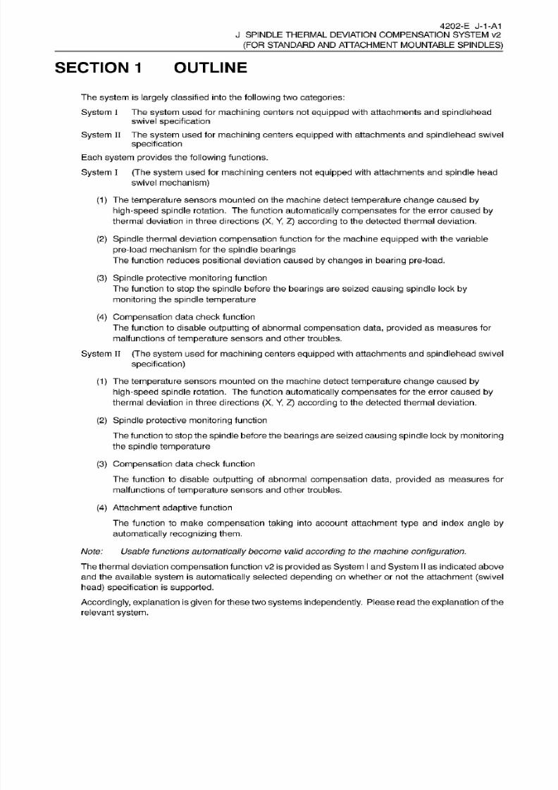
8/15/2019 Okuma Manuals 391
http://slidepdf.com/reader/full/okuma-manuals-391 329/397
4202-
E J-1-A1
J SPINDLE
THERMAL
DEVIATION COMPENSATION SYSTEM
v2
(FOR
STANDARD
AND
ATTACHMENT MOUNTABLE
SPINDLES)
SECTION
1
OUTLINE
The
system
is
largely
classified into
the
following
two
categories:
System
I
The
system
used for
machining
centers not
equipped
with
attachments
and
spindlehead
swivel specification
System
II
The
system
used for machining
centers equipped with attachments
and
spindlehead
swivel
specification
Each
system
provides
the
following
functions.
System
I
(The
system
used for
machining
centers not equipped with attachments an d
spindle
head
swivel mechanism)
(1)
The
temperature
sensors mounted on themachine detect
temperature
change caused by
high-speed spindle
rotation.
The
function
automatically
compensates for
the
error
caused by
thermal
deviation
in three directions (X,
Y, Z)
according
to
the detected thermal deviation.
(2)
Spindle thermal deviation
compensation
function for
the
machine equipped with the variable
pre-load mechanism for the spindle
bearings
The function reduces
positional
deviation
caused by changes in bearing
pre-load.
(3) Spindle
protective monitoring
function
The function to
stop
the
spindle
before the
bearings
are seized
causing
spindle
lock
by
monitoring
the
spindle
temperature
(4)
Compensation
data check function
The
function to disable
outputting of abnormal
compensation
data,
provided as
measures for
malfunctions
of
temperature
sensors
an d
other
troubles.
System
II (The
system
used for
machining
centers
equipped
with attachments and
spindlehead swivel
specification)
(1) The temperature sensors mounted
on
the machine detect
temperature change
caused
by
high-speed
spindle rotation. The function
automatically compensates
for the error caused
by
thermal
deviation in three
directions
(X,
Y,
Z)
according
to
the
detected thermal deviation.
(2)
Spindle protective
monitoring
function
The function to
stop
the
spindle
before the
bearings
are seized
causing
spindle
lock
by monitoring
the
spindle temperature
(3)
Compensation
data check function
The function
to disable
outputting
of abnormal
compensation
data,
provided
as measures
for
malfunctions
of temperature
sensors
and
other troubles.
(4)
Attachment
adaptive
function
The
function
to make
compensation
taking
into
account
attachment
type
and index
ang le by
automatically
recognizing
them.
Note: Usable
functions
automatically
become valid
according
to the machine
configuration.
The thermal deviation
compensation
function
v2
is
provided
as
System
I
and
System
II
as
indicated above
and the available
system
is
automatically
selected
depending on
whether or not the
attachment (swivel
head)
specification
is
supported.
Accordingly,
explanation
is
given
for these
two
systems
independently.
Pleaseread theexplanation
of
the
relevant
system.
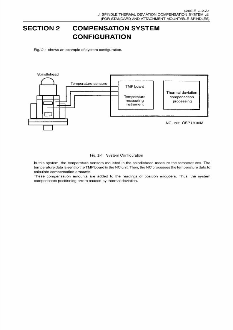
8/15/2019 Okuma Manuals 391
http://slidepdf.com/reader/full/okuma-manuals-391 330/397
4202-E
J-2-A1
J SPINDLE
THERMAL
DEVIATION COMPENSATION SYSTEM v2
(FOR
STANDARD
AND
ATTACHMENT MOUNTABLE
SPINDLES)
SECTION 2 COMPENSATION SYSTEM
CONFIGURATION
Fig.
2-1
shows an example
of
system
configuration.
Spindlehead
a Temperature
sensors
TM P
board
Thermal
deviation
compensation
processing
Temperature
measuring
instrument
zn
NC unit: OSP-U100M
Fig. 2-1 System Configuration
In
this system, the temperature sensors
mounted in
the
spindlehead
measure
the
temperatures. The
temperature
data issent to
theTMP
board
in
the NC unit.
Then,
the NC
processes
the
temperature
data to
calculate
compensation amounts.
These
compensation
amounts
are
added to
the
readings
of
position
encoders. Thus, the
system
compensates positioning
errors
caused
by
thermal deviation.
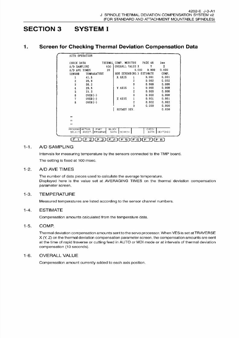
8/15/2019 Okuma Manuals 391
http://slidepdf.com/reader/full/okuma-manuals-391 331/397
4202-E J-3-A1
J SPINDLE
THERMAL
DEVIATION COMPENSATION SYSTEM v2
(FOR
STANDARD
AND
ATTACHMENT MOUNTABLE
SPINDLES)
SECTION 3 SYSTEM
I
Screen for Checking
Thermal Deviation
Compensation
Data.
AUTO
OPERATION
THERMAL
COMP.
MONITOR
PAGE
46
100
OVERALL
VALUE
X
In
HECK DATA
A/D
SAMPLING
A/D
AVE
TIMES
SENSOR
TEMPARATURE
Y Z
0.000.000 0.000
HOT SENSOR
(NO. )
ESTIMATE
X
AXIS
1
20
COMP.
0.001
0.002
0.000
0.000
0.000
0.000
0.001
0.002
0.000
0.001
0.002
0.000
0.000
0. 000
0.000
0.001
0.002
0.000
0.000
41.6
2
5.9
3
6.2
29.5
Y
AXIS
1
21.3
2
OVER
(-)
OVER
(-)
OVER(-)
3
Z
AXIS
1
2
3
ROTARY
DEV.
PROGRAM
ACTUAL
PART BLOCK
SELECT
POSIT.
FROGRAH
DATA SEARCH
CHECK
DATA
[EXTEND:
1-1.
A/D
SAMPLING
Intervals for measuring
temperature
by the sensors connected to the TM P
board.
The
setting
is fixed
at
100
msec.
1-2.
A/D
AVE
TIMES
The number of data
pieces used
to calculate the
average temperature.
Displayed here is the value
set
at
AVERAGING
TIMES
on the
thermal
deviation compensation
parameter
screen.
1-3. TEMPERATURE
Measured temperatures are listed
according
to
the
sensor channel
numbers.
1-4.
ESTIMATE
Compensation
amounts
calculated
from the
temperature
data.
1-5. COMP.
Thermal deviation compensation amounts
sent to the
servo
processor.
When YES is
set
at
TRAVERSE
X
(Y, Z)
on the thermal deviation
compensation
parameter
screen,
the
compensation amounts
are sent
at the time of
rapid
traverse or
cutting
feed
in
A UT O or
MDI mode
or at intervals of
thermal deviation
compensation
(10
seconds).
1-6. OVERALL
VALUE
Compensation
amount
currently
added to each
axis
position.

8/15/2019 Okuma Manuals 391
http://slidepdf.com/reader/full/okuma-manuals-391 332/397
4202-
E J-4-A1
J SPINDLE
THERMAL
DEVIATION COMPENSATION SYSTEM v2
(FOR
STANDARD
AND
ATTACHMENT MOUNTABLE
SPINDLES)
AXIS
(Thermal Deviation)
1/2/3
-7.
These represent
the
compensation
measures to be used for
compensating
for deviation
on the
individual
axes
and
designation
is
possible
for
up
to
3
kinds.
1-8.
ROTARY DEV.
This
represents
deviation to
reduce the influence
of
positional changes
(spindle deviation) when
spindle
bearing
pre-load changes
(for the
spindle equipped
with
pre-loading position
variable
bearings)
and
that
of tool
edge
positional
deviation due
to rotation.
This
compensation
amount is
added
to OVERALL
VALUE
Z.

8/15/2019 Okuma Manuals 391
http://slidepdf.com/reader/full/okuma-manuals-391 333/397
4202-E J-5-A1
J SPINDLE
THERMAL
DEVIATION COMPENSATION SYSTEM v2
(FOR
STANDARD
AND
ATTACHMENT MOUNTABLE
SPINDLES)
2.
Alarm
Message
<
Alarm P
>
AD P
START818
An
alarm
occurred
while
the
AD
conversion
processor
board was initial ized after
power
ON.
[Index]
None
[Character-string] None
[Code]
X
X=1:
Synchronous counter value
remains
1
.
X=2:
A
system
alarm occurred when the
synchronous
counter
value was 1
.
X=3:
Synchronous
counter
value remains
3.
X=4: A
system
alarm
occurred when the
synchronous
counter
value
was
3.
[Probable
Faulty
Locations]
TM P
board
(Thermal deviation AD
conversion processor
board)
[Measures
to Take]
Replace the TM P board.
[Remark]
If
a
TM P board
is not
connected,
this alarmdoesnot
occur
but theNC entersthe halt state due to access
to
the
shared RAM
of
TM P
and restart
is disabled.
<
Alarm-A
>
Thermal deviation
compensation
Temperature
rise calculated based
on the
axis deviation amounts of the individual axes exceeded the
temperature
limits set
for them.
[Index] None
[Character-string]
None
[Code]
XY
X=1:
Temperature
r ise exceeded the limit.
Y=1: X-axis
thermal
deviation 1
Y=2: X-axis thermal deviation 2
Y=3:
X-axis thermal deviation
3
Y=4:
Y-axis
thermal
deviation
1
Y=5:
Y-axis
thermal
deviation
2
Y=6:
Y-axis
thermal
deviation 3
Y=7: Z-axis thermal deviation 1
Y=8:
Z-axis thermal
deviation
2
Y=9:
Z-axis
thermal deviation
3
Y=A: Deviation
of
attachment
spindle
[Probable
Faulty
Locations]
1)
Abnormal
TMP,
or
the
machine
is
generating
abnormal heat.
2)
The
limit
value set for
the
parameter
of
the corresponding
channel is too
small,
or
the
machine
1307
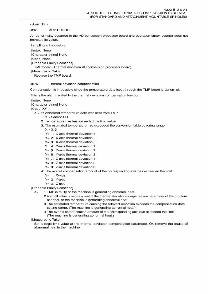
8/15/2019 Okuma Manuals 391
http://slidepdf.com/reader/full/okuma-manuals-391 334/397
4202-E J-6-A1
J SPINDLE
THERMAL
DEVIATION COMPENSATION SYSTEM v2
(FOR
STANDARD
AND
ATTACHMENT MOUNTABLE
SPINDLES)
<Alarm
D
>
AD P
ERROR261
An abnormality
occurred
in the
AD conversion processor board and
operation
check counter does not
increase
its
value.
Sampling is
impossible.
[Index]
None
[Character-string]
None
[Code]
None
[Probable
Faulty
Locations]
TMP
board
(Thermal
deviation
AD
conversion
processor
board)
[Measures to
Take]
Replace
the TM P
board.
Thermal deviation
compensation
Compensation
is
impossible
since
the
temperature
data
input through
the
TMP
board is abnormal.
This
is the alarm related to the thermal deviation
compensation
function.
[Index]
None
[Character-string]
None
[Code] XY
X
=
1
:
Abnormal
temperature
data
was
sent
from
TMP.
Y
=
Sensor CH
2:
Temperature
rise has exceeded
the
limit value.
3:
The estimated
temperature
has
exceeded
the conversion
table
covering
range.
X
=2,
3
Y= 1
:
X-axis
thermal
deviation
1
Y=
2:
X-axis
thermal deviation
2
Y=
3: X-axis thermal deviation 3
Y=
4: Y-axis
thermal
deviation
1
Y= 5:
Y-axis thermal deviation
2
Y=
6:
Y-axis
thermal deviation
3
Y= 7: Z-axis thermal deviation 1
Y= 8:
Z-axis thermal deviation 2
Y= 9:
Z-axis thermal deviation
3
4: The overall
compensation amount of
the
corresponding
axis
ha s
exceeded the limit.
Y=
1: X-axis
Y=
2:
Y-axis
Y=
3:
Z-axis
4275
[Probable
Faulty
Locations]
X= 1 TM P
is
faulty
or the
machine is
generating
abnormal heat.
2
A
small value
is
set
as
a limit
at
the thermal deviation
compensation parameter
of the problem
channel,
or the
machine
is
generating
abnormal heat.
3
The
estimated
temperature
causing the relevant deviation exceeds
the
compensation
data
setting range.
(The machine is
generating
abnormal
heat.)
4
The overall
compensation
amount of the
corresponding
axis has exceeded the limit.
(The
machine
is
generating abnormal heat.)
[Measures
to
Take]
Set a
large limit value at the thermal
deviation compensation
parameter. Or,
remove the cause
of
abnormal heat
in
the
machine.

8/15/2019 Okuma Manuals 391
http://slidepdf.com/reader/full/okuma-manuals-391 335/397
4202-E
J-7-A1
J SPINDLE
THERMAL
DEVIATION COMPENSATION SYSTEM v2
(FOR
STANDARD
AND
ATTACHMENT MOUNTABLE
SPINDLES)
[Related
Specifications]
Thermal deviation
compensation
Thermistor error284
[Index]
None
[Character-string] None
[Code]
Sensor
CH
[Probable
Faulty
Locations]
1)
The corresponding
temperature
sensor is malfunctioning
or its
wiring
is broken.
2)
The
TM P
is
faulty.
[Measures
to Take]
1)
Check
if
the corresponding
temperature
sensor is mounted
correctly.
2)
Replace
the
temperature
sensor.
[Others]
-
The
compensation
amount becomes
“0 ”
for deviation
which
is detected
by
a
malfunctioning sensor.
-
Fo r
sensor
channels
7
and
8
used for
the
attachment
specification,
this alarm
does
not occur.
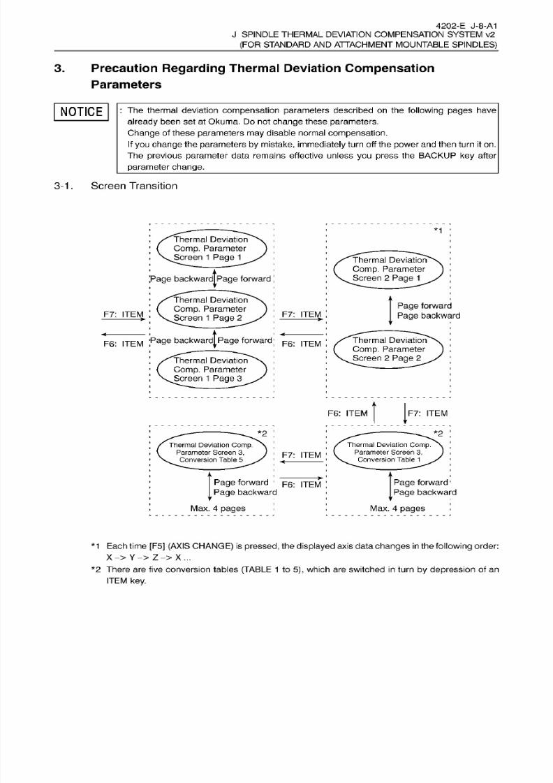
8/15/2019 Okuma Manuals 391
http://slidepdf.com/reader/full/okuma-manuals-391 336/397
4202-E J-8-A1
J SPINDLE
THERMAL
DEVIATION COMPENSATION SYSTEM v2
(FOR
STANDARD
AND
ATTACHMENT MOUNTABLE
SPINDLES)
3.
Precaution
Regarding
Thermal
Deviation
Compensation
Parameters
NOTICE
: The thermal deviation compensation
parameters
described
on
the following
pages
have
already
been
set
at
Okuma. Do
not
change
these
parameters.
Change of
these
parameters
may
disable normal compensation.
If
you
change
the
parameters
by
mistake, immediately turn off
the
power
and
then
turn
it on .
The
previous parameter
data remains effective unless yo u press the BACKUP
key
after
parameter
change.
3-1
.
Screen Transition
*1
Thermal Deviation
Comp.
Parameter
Screen
1 Page
1
Thermal
Deviation
Comp.
Parameter
Screen
2 Page
1
age
backward|page
forward
Thermal
Deviation
Comp.
Parameter
Screen
1
Page
2
Page
forward
Page
backward
7:
ITEM
F7:
ITEM
Page
backwardjpage
forward
Thermal Deviation
Comp. Parameter
Screen
2
Page
2
F6:
ITEM
F6:
ITEM
Thermal Deviation
Comp.
Parameter
Screen
1 Page
3
F6:
ITEM F7 : ITEM
*2
*2
Thermal Deviation
Comp.
Parameter Screen
3,
.
Conversion
Table
5
Thermal
Deviation
Comp.
Parameter
Screen
3,
Conversion
Table
1
7: ITEM
Page forward
1
F6 :
|TEM
Page
backward
Max. 4
pages
Page forward
1
Page
backward
Max.
4
pages
*1
Each time [F5]
(AXIS CHANGE)
is
pressed,
the
displayed
axis data
changes
in the
following
order:
X Y
Z
X...
*2 There are
five
conversion
tables
(TABLE
1
to
5),
which
are
switched
in
turn
by
depression
of an
ITEM
key.
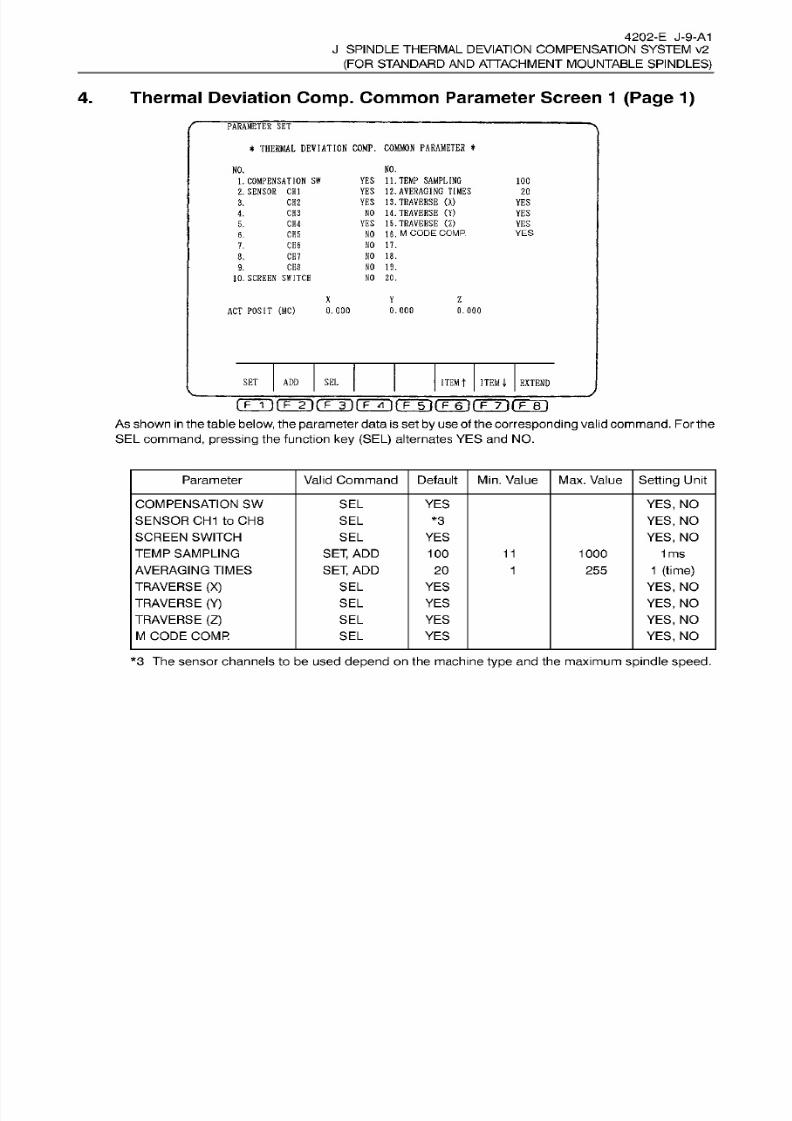
8/15/2019 Okuma Manuals 391
http://slidepdf.com/reader/full/okuma-manuals-391 337/397
4202-E J-9-A1
J
SPINDLE THERMAL
DEVIATION
COMPENSATION SYSTEM v2
(FOR STANDARD
AN D
ATTACHMENT
MOUNTABLE
SPINDLES)
4. Thermal Deviation
Comp.
Common
Parameter Screen
1 (Page 1)
PARAMBTER
SET
*
THERMAL DEVIATION
COMP.
COMMON
PARAMETER
*
NO.
O.
YES
11.
TEMP SAMPLING
YES
12.
AVERAGING TIMES
YES 13. TRAVERSE
(X)
NO 14.
TRAVERSE
(Y)
YES
15.
TRAVERSE
(Z)
NO
16.
M
CODE COMP.
NO
17.
NO 18.
NO 19.
NO
20.
1.
COMPENSATION
SW
2. SENSOR
CHI
100
20
3.
CH2
YE S
CH3
.
YE S
CH4 YES.
YES
H5.
CH6
.
8.
CH7
CE8
.
10.
SCREEN SWITCH
X
Y
Z
AC T
POSIT
(MC)
0.000
0.000
0.000
ITEM
t ITEMI
EXTEND
ET ADD
SE L
t
p
IMP 2i rmi
F
YI
i
rmnÿrrn
(Tin
Asshown
in
the
table
below,
theparameter data is set
by
use
of the corresponding
valid
command.
For
the
SEL command,
pressing the function
ke y (SEL)
alternates YES and NO.
Parameter Valid
Command
Default
Min.
Value Max. Value Setting Unit
COMPENSATION
SW
SENSOR
CH 1
to
CH8
SCREEN SWITCH
TEMP
SAMPLING
AVERAGING TIMES
TRAVERSE (X)
TRAVERSE
(Y)
TRAVERSE
(Z)
M
CODE COMR
SE L
YES YES,
NO
YES,
NO
YES,
NO
1
ms
1 (time)
YES,
NO
YES,
NO
YES, NO
YES,
NO
SE L
*3
SE L
YE S
SET,
AD D
SET,
AD D
11
00 1000
255
0
1
SEL YES
SEL YES
SE L YE S
SE L YES
*3 The
sensor
channels to be used depend on the machine type and the maximum spindle speed.
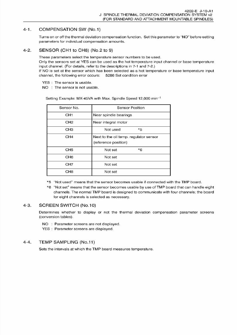
8/15/2019 Okuma Manuals 391
http://slidepdf.com/reader/full/okuma-manuals-391 338/397
4202-E J-10-A1
J SPINDLE
THERMAL
DEVIATION COMPENSATION SYSTEM v2
(FOR
STANDARD
AND
ATTACHMENT MOUNTABLE
SPINDLES)
4-1
. COMPENSATION SW
(No.1)
Turns
on
or off the thermal deviation
compensation
function.
Set
this
parameter
to “NO
before setting
parameters
for individual
compensation
amounts.
4-2.
SENSOR
(CH1
to
CH8)
(No.2
to
9)
These
parameters
select
the
temperature
sensor numbers to be used.
Only the
sensors
set
at
YES
can
be used as the hot
temperature
input channel or base
temperature
input
channel. (For details,
refer
to the
descriptions
in
7-1 and 7-2.)
If NO is
set at
the sensor which has been selected as
a
ho t
temperature
or base
temperature input
channel,
the
following
error occurs:
5286
Set
condition error
YE S : Th e sensor is usable.
NO
:
The sensor is
not
usable.
Setting
Example:
MX-45VA
with Max.
Spindle Speed 12,000
min-1
Sensor No. Sensor
Position
CH 1 Near spindle
bearings
CH2 Near
integral
motor
CH3 Not
used
*5
CH 4 Next
to
the oil temp,
regulator
sensor
(reference position)
CH5
Not set *6
CH 6
Not set
CH 7
Not set
CH8 Not set
*5
“Not used”
means
that the
sensor
becomes usable if connected with the
TMP
board.
*6 “Not
set”
means that the
sensor
becomes usable
by
use o f
TMP
board that can
handle
eight
channels. Th e normal TM P board is
designed
to communicate with
four
channels;
the board
for
eight
channels is selected
as
necessary.
4-3.
SCREEN SWITCH
(No.
10)
Determines whether to display or not the
thermal
deviation
compensation parameter
screens
(conversion tables).
NO :
Parameter
screens
are not
displayed.
YE S
:
Parameter screens are
displayed.
4-4. TEMP
SAMPLING (No.1
1
)
Sets the intervals
at
which the
TMP
board
measures temperature.

8/15/2019 Okuma Manuals 391
http://slidepdf.com/reader/full/okuma-manuals-391 339/397
4202-E
J-11-A1
J SPINDLE
THERMAL
DEVIATION COMPENSATION SYSTEM v2
(FOR
STANDARD
AND
ATTACHMENT MOUNTABLE
SPINDLES)
4-5. AVERAGING
TIMES
(No.
12)
Determines the number
of
temperature
data
pieces
to
be collected
and
averaged.
4-6. TRAVERSE
(X), (Y), (Z) (No.1
3
to 1
5)
The thermal deviation
compensation
data
in
the
servo processor
is
updated
at
the
time
of
X-
(Y-
or
Z-)
axis
movement
in AUTO
or
MDI
mode or at intervals
(10 seconds)
for
compensating
thermal deviation.
This parameter
chooses
the
update
timing.
YE S
:
The
compensation
amount
is
updated
when
X-(Y-
or
Z-) axis
is
moved
(by
rapid
traverse or
cutting
feed)
in
AUTO
or
MDI
mode.
NO : The
compensation amount
is
updated
every
10 seconds (thermal
deviation compensation
interval).
4-7.
M
CODE
COMP.
(NO.16)
This
parameter
makes
“M297”
code valid. This code
specifies updating
of
the
thermal deviation
compensation
amount to be sent to
the
servo
processor
even
during machining
that is not
associated
with axis movements.
M297 updates
the
compensation
amount
only
when
the setting
for No.
13/14/15
‘‘TRAVERSE
(X)/(Y)/(Z)” is
“YES” with the
setting
for this
parameter
“YES”.
If the
setting
for this
parameter
is
“NO”,
compensation
amount is not
updated
even
if
M297
is
specified.
YES : Updating
of
the
compensation
amount,
specified
by
M297,
is valid.
NO
:
Updating
of
the compensation
amount,
specified
by
M297, is invalid.
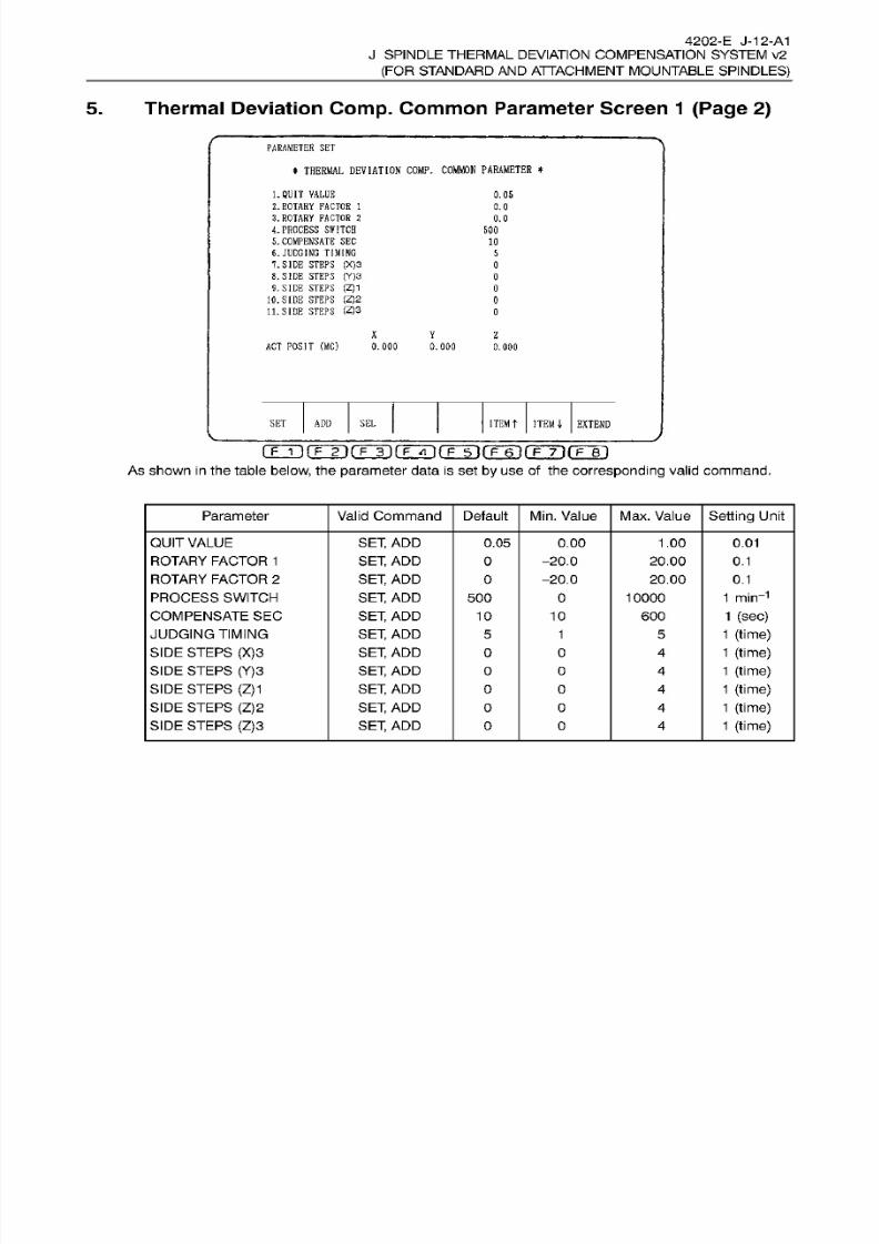
8/15/2019 Okuma Manuals 391
http://slidepdf.com/reader/full/okuma-manuals-391 340/397
4202-E
J-12-A1
J
SPINDLE THERMAL DEVIATION COMPENSATION SYSTEM v2
(FOR STANDARD
AN D
ATTACHMENT
MOUNTABLE
SPINDLES)
5. Thermal Deviation
Comp.
Common
Parameter Screen
1 (Page
2)
PARAMETER
SET
*
THERMAL
DEVIATION
COMP.
COMMON PARAMETER
*
1. QUIT
VALUE
2. ROTARY
FACTOR
1
3. ROTARY
FACTOR
2
4.
PROCESS SWITCH
5.
COMPENSATE
SE C
6.
JUDGING
TIMING
7.
SIDE
STEPS
(X)3
8. SIDE STEPS
(Y)3
9.
SIDE STEPS
(Z)1
10.
SIDE STEPS
(Z)2
11. SIDE STEPS
(Z)3
0.05
0.0
0.0
50 0
10
5
0
0
0
0
0
X Y
Z
ACT
POSIT
(MC)
0.000
0.000
0.000
SEL
ITEM
T
ITEM
4-
EXTEND
ET ADD
rrr i rKÿrFÿfFÿ(TTinr6~irF~nr?~6T
As
shown
in
the table
below,
the parameter data
is
set
by
use
of
the
corresponding
valid command.
Parameter
Valid
Command Default
Min.
Value
Max. Value
Setting
Unit
QUIT
VALUE
ROTARY FACTOR
1
ROTARY
FACTOR
2
PROCESS SWITCH
COMPENSATE
SEC
JUDGING TIMING
SIDE STEPS
(X)3
SIDE
STEPS (Y)3
SIDE
STEPS
(Z)1
SIDE
STEPS
(Z)2
SIDE STEPS
(Z)3
SET,
AD D
SET, AD D
SET,
AD D
SET,
AD D
SET,
AD D
SET,
AD D
SET,
AD D
SET,
AD D
SET,
AD D
SET,
AD D
SET, AD D
0.05 0.00 1.00
0.01
O -20.0
-20.0
20.00
20.00
0.1
0
0.1
1 min-1
1 (sec)
1 (time)
1 (time)
1
(time)
1 (time)
1
(time)
1 (time)
0
00 10000
10
10
600
5 1
5
O
0
4
O 0 4
O
0
4
O
0
4
O 0 4
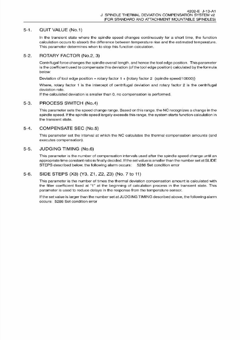
8/15/2019 Okuma Manuals 391
http://slidepdf.com/reader/full/okuma-manuals-391 341/397
4202-E J-13-A1
J SPINDLE
THERMAL
DEVIATION COMPENSATION SYSTEM v2
(FOR
STANDARD
AND
ATTACHMENT MOUNTABLE
SPINDLES)
5-1.
QUIT
VALUE
(No.1)
In
the transient state where the
spindle
speed changes
continuously
for
a short
time,
the function
calculation
occurs
to absorb
the
difference between
temperature
rise and
the
estimated
temperature.
This
parameter
determines
when to
stop
this
function calculation.
5-2. ROTARY FACTOR (No.2 ,
3)
Centrifugal
force
changes the spindle
overall
length,
and
hence the
tool
edge position.
This parameter
is the coefficient
used to
compensate
this deviation
(of
the tool
edge position)
calculated
by
the formula
below:
Deviation of tool
edge
position
=
rotary
factor 1
+
{rotary
factor
2
(spindle
speed/10000)}
Where, rotary
factor 1 is
the
intercept
of
centrifugal
deviation and
rotary
factor
2
is
the centrifugal
deviation
rate.
If
the calculated deviation
is smaller
than
0,
no
compensation is
performed.
5-3.
PROCESS
SWITCH
(No.4)
This
parameter
sets
the speed
change range.
Based on this
range,
the NC
recognizes
a
change in
the
spindle speed.
If
the
spindle speed
largely
exceeds this
range, the
system
starts function calculation
in
the transient
state.
5-4.
COMPENSATE SEC
(No.5)
This
parameter
set the interval at which the NC calculates the thermal
compensation
amounts (and
executes
compensation).
5-5. JUDGING TIMING
(No.6)
This
parameter
is
the
number
of
compensation
intervals used
after
the spindle speed change
until
an
appropriate
time constant ratio
is
finally decided.
If
the set
value
is
smaller
than the number set at SLIDE
STEPS described
below,
the following
alarm
occurs: 5286 Se t condition error
5-6. SIDE STEPS
(X3) (Y3,
Z1,
Z2,
Z3)
(No. 7
to
11)
This
parameter
is the
number
of
times
the thermal deviation
compensation amount
is calculated with
the filter coefficient fixed at
“1”
at the
beginning
of
calculation
process
in the
transient
state. This
parameter
is
used
to reduce
delays in
the
response
from the
temperature
sensor.
If the
set value
is larger
than the number set at JUDGING TIMING described
above, the
following
alarm
occurs:
5286
Set condition error

8/15/2019 Okuma Manuals 391
http://slidepdf.com/reader/full/okuma-manuals-391 342/397
4202-E
J-14-A1
J SPINDLE
THERMAL
DEVIATION COMPENSATION SYSTEM v2
(FOR
STANDARD
AND
ATTACHMENT MOUNTABLE
SPINDLES)
Thermal
Deviation
Comp.
Common
Parameter Screen
1
(Page 3)
.
PARAMETER
SET
*
THERMAL
DEVIATION
COMP.
COMMON PARAMETER
*
12.
OVERALL
LIMIT
(X)
13. OVERALL
LIMIT
(Y)
14.
OVERALL LIMIT
(Z)
15 ,
ROTARY
DEV.
LIMIT
16.
ROTARY
DEV.
FACTOR
1
17.
ROTARY DEV. FACTOR
2
18.
ROTARY
DEV.
FACTOR
3
19.
ROTARY DEV.
FACTOR
4
20. ROTARY
DEV.
FACTOR
5
999
999
999
0.000
0.000
0.000
0.000
0.000
0.
000
Y
z
AC T POSIT
(MC)
0.000
.000
0.000
ITEMt
ITEM
4
EXTEND
ET
ADD
SE L
IF
i
)frÿrFÿfFÿ(T~5irF~6irÿTirF~e' i
As shown
in
the table
below,
the parameter
data
is
set
by
use of
the
corresponding
valid command.
Valid Command
Default
Setting
Unit
arameter
Min. Value
Max. Value
OVERALL
LIMIT
(X)
OVERALL
LIMIT
(Y)
OVERALL
LIMIT
(Z)
ROTARY
DEV.
LIMIT
ROTARY DEV
FACTOR
1
ROTARY
DEV.
FACTOR
2
ROTARY
DEV.
FACTOR 3
ROTARY
DEV.
FACTOR
4
ROTARY
DEV.
FACTOR
5
SET,
AD D
SET,
AD D
SET, AD D
SET,
ADD
SET,
AD D
SET, AD D
SET, AD D
SET,
AD D
SET, AD D
999 0
9999
9999
9999
1
[Am
1
[im
1
[im
0.001
mm
0.001
0.001
0.001
0.001
0.001
999
0
999 0
0.000
0.000
0.000
0.000
0.000
0.000
-1
.000
-15.000
0.000
0.000
-15.000
-15.000
1.000
15.000
30.000
30.000
15.000
15.000
OVERALL
LIMIT
(X), (Y),
(Z)
(NO.
12
to
14)
This
parameter
sets the
limit
value of
the compensation amount for
the
corresponding
axis.
If
the overall
compensation
amount
including
the
deviation of
tool
edge
position
exceeds
the set
limit
value,
the overall
compensation
amount is
replaced
with
the
limit
value
set for
this
parameter.
The set
value is treated
in
an absolute value.
If
this
replacement
occurs,
the following alarm
occurs: Alarm
D
4275
Thermal deviation
compensation.
ROTARY
DEV. LIMIT
(NO. 15)
This
parameter
sets the maximum
(minimum)
value of
rotary
deviation
compensation
amount.
If
the
rotary
deviation compensation amount
exceeds
the set limit
value,
the rotation deviation
compensation
amount
is
replaced
with the
value set for this
parameter.
ROTARY
DEV. FACTOR
1
,
2,
3,
4
(NO.
16 to
19)
These are
factors
used to calculate
rotary
deviation amount.
ROTARY DEV.
FACTOR 5
(NO.
20)
This is
a
factor
used
to
calculate
rotary
deviation
amount.
6-1.
6-2.
6-3.
6-4.
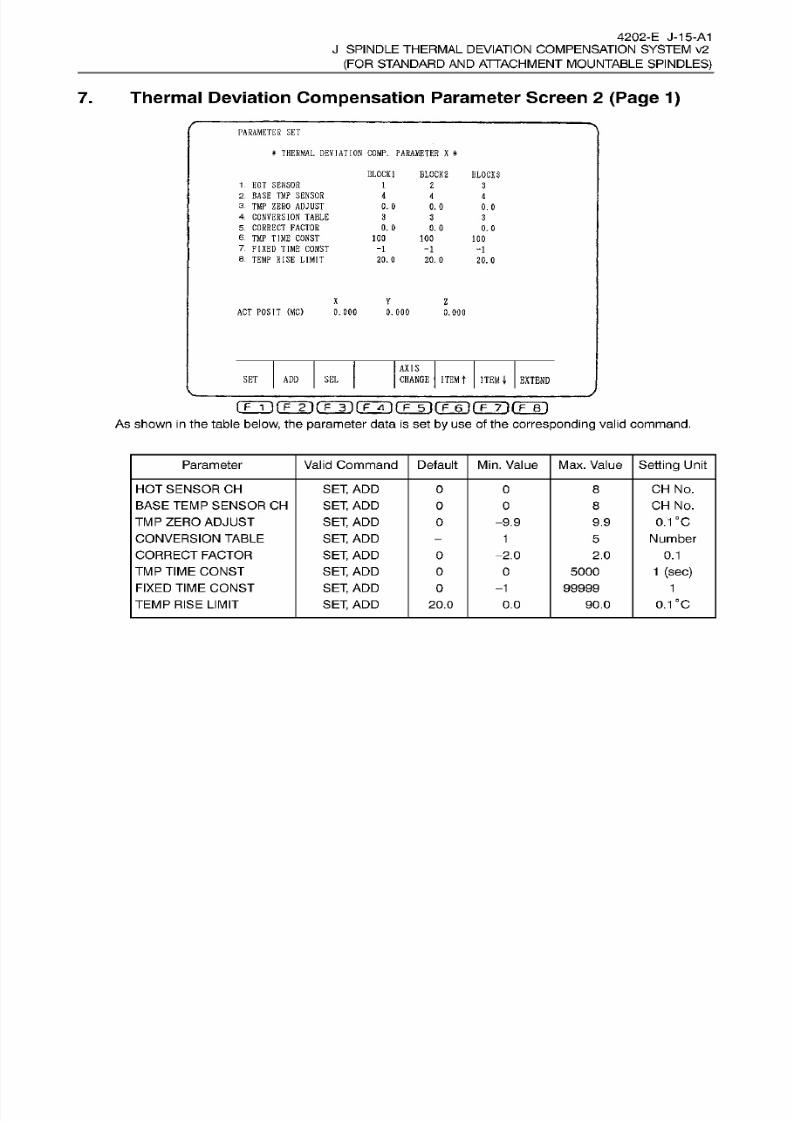
8/15/2019 Okuma Manuals 391
http://slidepdf.com/reader/full/okuma-manuals-391 343/397
4202-E J-15-A1
J
SPINDLE THERMAL DEVIATION COMPENSATION SYSTEM v2
(FOR STANDARD
AN D
ATTACHMENT
MOUNTABLE
SPINDLES)
7.
Thermal Deviation
Compensation
Parameter Screen
2 (Page 1)
PARAMETER
SET
*
THERMAL
DEVIATION
COMP.
PARAMETER X
*
BLOCK]
BLOCK 2
BLOCK
3
1.
HO T SENSOR
2.
BASE
TMP SENSOR
3.
TMP ZERO ADJUST
4
CONVERSION
TABLE
5
CORRECT
FACTOR
6.
TM P
TIME
CONST
7.
FIXED
TIME
CONST
8.
TEMP
RISE
LIMIT
1
2
3
4
4
4
0. 0
0.
0
0.0
3
3 3
0.
0
0. 0
0.
0
100
100
100
-1
-1
-1
20.0 20.
0
20.0
X
V Z
ACT POSIT
(MC)
0.000
0.000
0. 000
AXIS
SE L
CHANGE
ITEM
T
ITEM
4-
EXTEND
ET
ADD
As
shown
in
the table
below,
the parameter data
is
set
by
use
of the corresponding
valid
command.
Parameter
Valid
Command Default
Min.
Value
Max. Value
Setting
Unit
HOT SENSOR CH
BASE
TEMP
SENSOR CH
TM P ZERO
ADJUST
CONVERSION
TABLE
CORRECT
FACTOR
TMP TIME
CONST
FIXED
TIME
CONST
TEMP
RISE
LIMIT
SET,
AD D
SET, AD D
SET,
AD D
SET,
AD D
SET,
AD D
SET,
AD D
SET,
AD D
SET,
AD D
CH
No.
CH
No.
0.1
'C
Number
O
0 8
0
0 8
O
-9.9 9.9
1
5
-2.0 2.0
0.1
1
(sec)
0
5000
99999
-1 1
0.1
°c
0.0 0.0 90.0
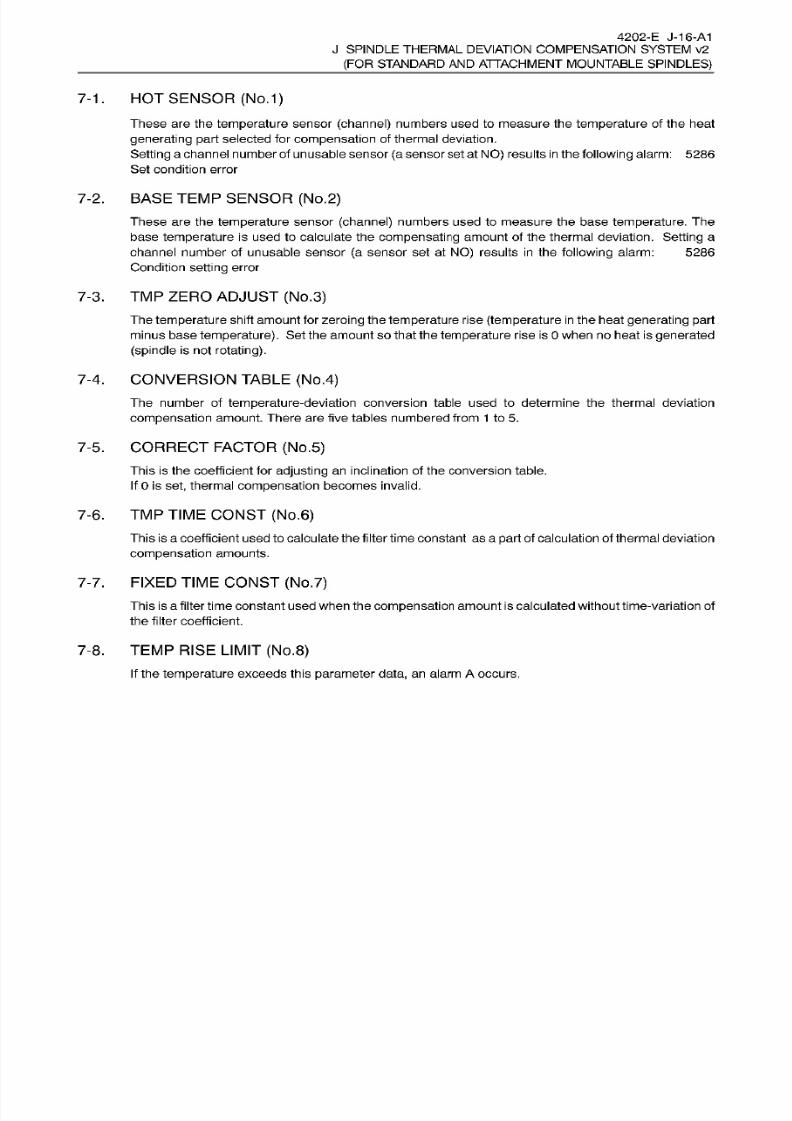
8/15/2019 Okuma Manuals 391
http://slidepdf.com/reader/full/okuma-manuals-391 344/397
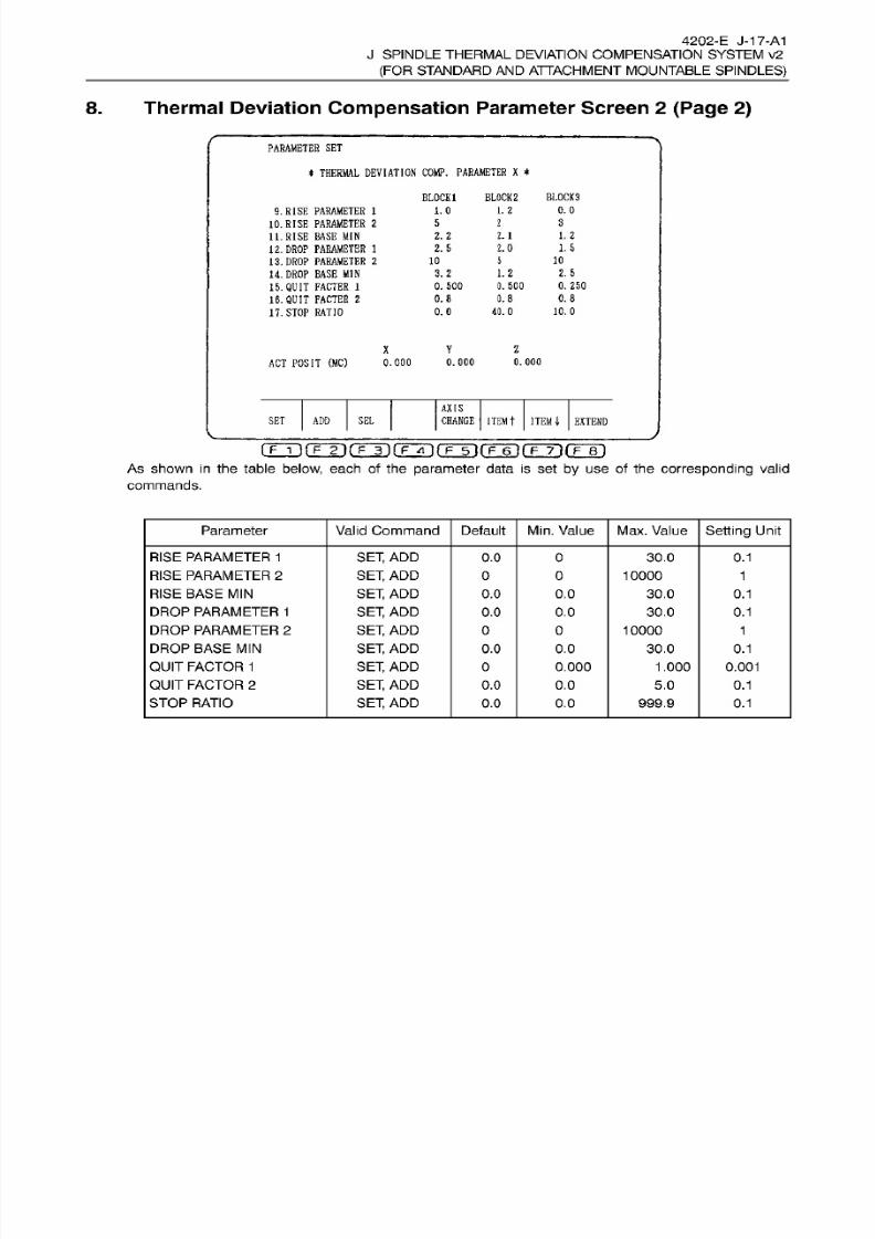
8/15/2019 Okuma Manuals 391
http://slidepdf.com/reader/full/okuma-manuals-391 345/397
4202-E
J-17-A1
J
SPINDLE THERMAL DEVIATION COMPENSATION SYSTEM v2
(FOR STANDARD
AN D
ATTACHMENT
MOUNTABLE
SPINDLES)
8. Thermal Deviation
Compensation
Parameter Screen
2 (Page
2)
PARAMETER
SE T
*
THERMAL
DEVIATION
COMP.
PARAMETER
X
*
BLOCK
1
BLOCK
2
BL0CK3
1.2 0.0
.0
.
RISE
PARAMETER
1
10.
RISE PARAMETER
2
11.
RISE BASE
MIN
12.
DROP
PARAMETER
1
13.
DROP
PARAMETER
2
14.
DROP
BASE
MIN
15.
QUIT
FACTER 1
15.
QUIT
FACTER
2
17. STOP
RATIO
3
2
1. 2
.2
2.1
1.5
.
5
2.0
10
0
5
2.5
.2. 2
0. 500 0. 25 0
. 500
0.8
.8
0.8
10.0
.0
40.0
V
2
AC T
POSIT
(MC)
0.000
0.000
.000
AXIS
CHANGE
ITEM
t
ITEM
4-
EXTEND
ET ADD
SE L
A s show n
in the table below,
each
of
the parameter data
is
set
by
use
of
the
corresponding
valid
commands.
Parameter
Valid
Command
Default
Min.
Value Max. Value Setting Unit
RISE
PARAMETER 1
RISE
PARAMETER 2
RISE
BASE MIN
DROP
PARAMETER 1
DROP
PARAMETER
2
DROP BASE
MIN
QUIT
FACTOR
1
QUIT
FACTOR
2
STOP
RATIO
SET,
AD D
SET,
AD D
SET, AD D
SET,
AD D
SET,
AD D
SET, AD D
SET, AD D
SET,
AD D
SET, AD D
0.0 0 30.0 0.1
0
0 10000
1
0.0
0.0 30.0 0.1
0.1.0
0.0
30.0
0 0 10000 1
0.0 0.0 30.0
0.1
0
0.000
1.000 0.001
0.0
0.0 5.0 0.1
0.0 0.0 999.9
0.1

8/15/2019 Okuma Manuals 391
http://slidepdf.com/reader/full/okuma-manuals-391 346/397
4202-E J-18-A1
J SPINDLE
THERMAL
DEVIATION COMPENSATION SYSTEM v2
(FOR
STANDARD
AND
ATTACHMENT MOUNTABLE
SPINDLES)
8-1
. RISE
PARAMETER 1
,
RISE
PARAMETER 2,
RISE
BASE
MIN
(No.
9 to
11)
These
are
the
coefficients
used to determine the
appropriate
time
constant
ratio for
temperature
rise.
DROP
PARAMETER
1,
DROP
PARAMETER
2,
DROP BASE
MIN
(No.12to
14)
These are the
coefficients
used
to
determine the appropriate time
constant
ratio for temperature drop.
8-2.
8-3.
QUIT FACTOR
1
,
QUIT
FACTOR
2
(No.
15,
16)
These
are the coefficients
used to calculate the value for
stopping
calculation of the filter coefficient.
If
the
filter coefficient becomes smaller than the value calculated f rom these
values,
the
system stops
calculating
the
change
of
filter coefficient.
8-4.
STOP
RATIO (NO.
1
7)
This
is
a
factor
used
to
determine the
appropriate
time
constant
ratio for
stopping
the
spindle.
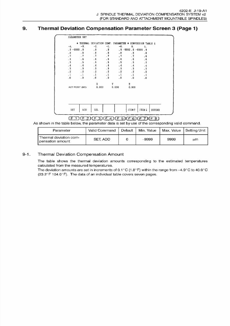
8/15/2019 Okuma Manuals 391
http://slidepdf.com/reader/full/okuma-manuals-391 347/397
4202-E J-19-A1
J
SPINDLE THERMAL
DEVIATION
COMPENSATION SYSTEM v2
(FOR STANDARD
AN D
ATTACHMENT
MOUNTABLE
SPINDLES)
9.
Thermal Deviation
Compensation
Parameter Screen 3
(Page 1)
PARAMETER
SE T
*
THERMAL
DEVIATION
COMP.
PARAMETER
*
CONVERSION
TABLE
1
-3. -2. -1.4.
-0.
0.
1.
.
9
-9999
.9 .9 .9
.
9
-9999
.
9
-9999
.9
.8
.8 .8
.8
.8
.8 .8
.7 .7 .7
7 .
7
.7
.8
.6 .85
.
6
.
6
.6
.8
.5
.
5
.
5
,5
.
5
.5
.
5
.4
,4
.4 .4
.4
.4 . 4
.3 .33
.
3
.
3
.3
.
3
.2 . 2
.
2 .
2
. 2
.2
.
2
. 1 . 1 .
1
.1
.1 .1
.1
.0 .0 .0
.0
.0
.0
.0
X Y
Z
0.000
0.000
0.
000
CT POSIT
(MC)
ITEM
t
ITEM;
EXTEND
ET ADD
SE L
(TTÿrrÿ(T~j) (ÿTn(Tÿ(TÿrFÿrrr i
As
shown
in
the table
below,
the parameter data
is
set
by
use
of the corresponding
valid
command.
Valid
Command
Default
Setting
Unit
arameter
Min.
Value
Max.
Value
Thermal deviation com¬
pensation
amount
SET, AD D
0 9999 9999 pm
9-1 . Thermal
Deviation
Compensation
Amount
The table
shows the
thermal deviation amounts corresponding
to
the
estimated
temperatures
calculated from the measured
temperatures.
The deviation
amounts
are set
in
increments
of 0.1°C
(1
.8°F) within the
range
from
—
4.9°C
to
40.0°C
(23.2°F
104.0°F). The data of an individual table covers seven
pages.
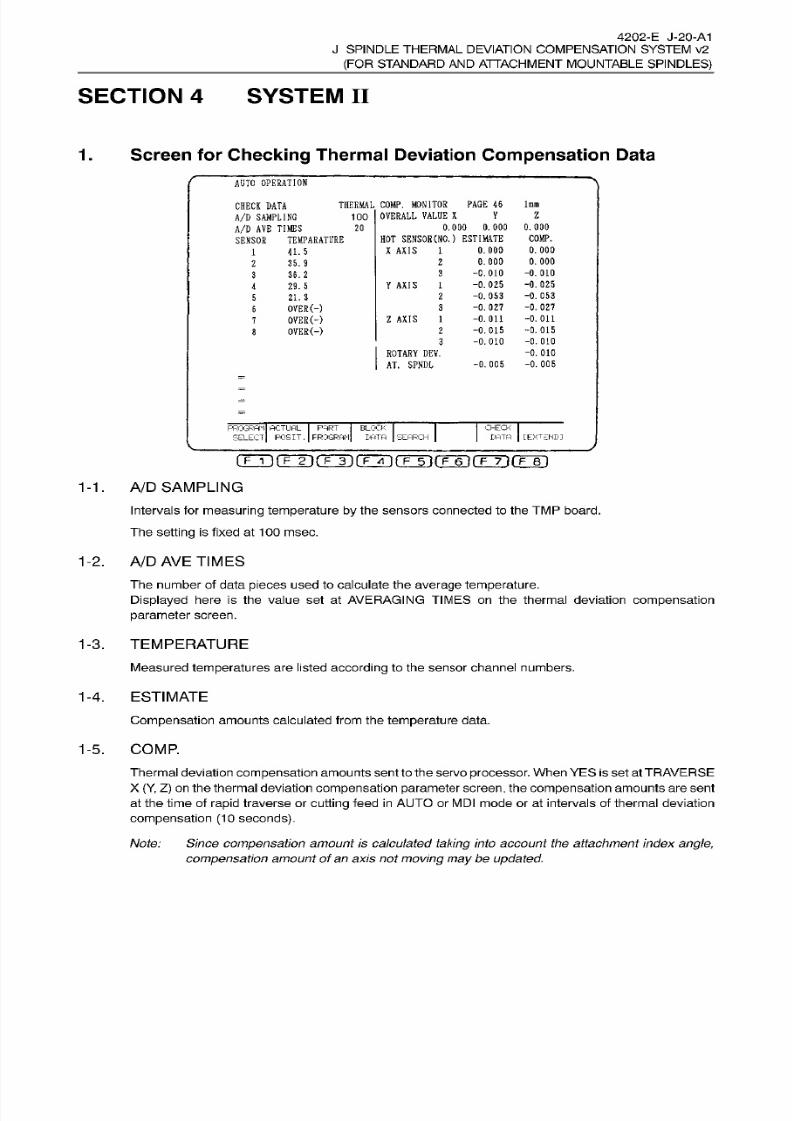
8/15/2019 Okuma Manuals 391
http://slidepdf.com/reader/full/okuma-manuals-391 348/397
4202-E J-20-A1
J SPINDLE
THERMAL
DEVIATION COMPENSATION SYSTEM v2
(FOR
STANDARD
AND
ATTACHMENT MOUNTABLE
SPINDLES)
SECTION 4 SYSTEM II
Screen for Checking
Thermal Deviation
Compensation
Data.
AUTO
OPERATION
THERMAL
COMP.
MONITOR
PAGE 46
100
OVERALL
VALUE X
lmm
HECK
DATA
A/D
SAMPLING
A/D
AVE
TIMES
SENSOR
TEMPARATURE
V
z
0. 000
0 . 0 00
HOT
SENSOR
(NO.
)
ESTIMATE
X AXIS
1
0.000
COMP.
0.
000
0.
000
-0.
010
-0.025
-0.053
-0.027
-0.011
-0.015
-0.010
-0.010
-0. 005
20
0.000
0.000
-0.010
-0.025
-0.053
-0.027
-0.011
-0.015
-0.010
41.5
2
5.9
3
6.
2
Y
AXIS
1
9.5
2
1.
3
OVER(-)
OVER(-)
OVER(-)
3
Z
AXIS
1
2
3
ROTARY
DEV.
AT.
SPNDL
-0.005
PROGRAM
ACTUAL
PART
BLOCK
SELECT
POSIT. FROGRAM LATA
SEARCH
CHECK
DATA
[EXTEND:
rrÿrr2 irrr iiTÿrr~ÿrF ~6 'i rrÿ-)rrB~ i
1-1.
A/D
SAMPLING
Intervals for measuring
temperature
by the sensors connected to the TM P
board.
The
setting
is fixed
at
100
msec.
1-2.
A/D
AVE
TIMES
The number of data
pieces used
to calculate the
average temperature.
Displayed here is the value
set
at
AVERAGING
TIMES
on the
thermal
deviation compensation
parameter
screen.
1-3. TEMPERATURE
Measured temperatures are listed
according
to
the
sensor channel
numbers.
1-4.
ESTIMATE
Compensation
amounts
calculated
from the
temperature
data.
1-5. COMP.
Thermal deviation compensation amounts
sent to the
servo
processor.
When YES is
set
at
TRAVERSE
X
(Y, Z)
on the thermal deviation
compensation
parameter
screen,
the
compensation amounts
are sent
at the time of
rapid
traverse or
cutting
feed
in
A UT O or
MDI mode
or at intervals of
thermal deviation
compensation
(10
seconds).
Note: Since
compensation
amount is calculated
taking
into account the attachment index
angle,
compensation
amount
of
an axis not
moving
may
be
updated.
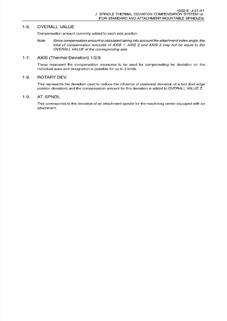
8/15/2019 Okuma Manuals 391
http://slidepdf.com/reader/full/okuma-manuals-391 349/397
4202-E
J-21-A1
J SPINDLE
THERMAL
DEVIATION COMPENSATION SYSTEM v2
(FOR
STANDARD
AND
ATTACHMENT MOUNTABLE
SPINDLES)
1-6. OVERALL
VALUE
Compensation
amount
currently
added
to each
axis
position.
Note: Since compensation amount is calculated
taking
into account
the attachment
index angle, the
total of compensation
amounts
of
AXIS 1, AXIS
2
and AXIS
3
may
not be equal
to
the
OVERALL
VALUE
of
the
corresponding
axis.
1-7.
AXIS
(Thermal Deviation)
1/2/3
These
represent
the
compensation
measures
to
be
used for
compensating
for dev ia tion on the
individual axes and designation is possible for
up
to 3 kinds.
1-8.
ROTARY DEV.
This
represents the deviation
used
to
reduce
the influence of
positional
deviation of
a tool (tool edge
position
deviation) and the
compensation
amount for this deviation is
added
to OVERALL VALUE
Z.
1-9.
AT.
SPNDL
This
corresponds
to
the deviation of
an
attachment
spindle
for
the
machining
center
equipped
with
an
attachment.
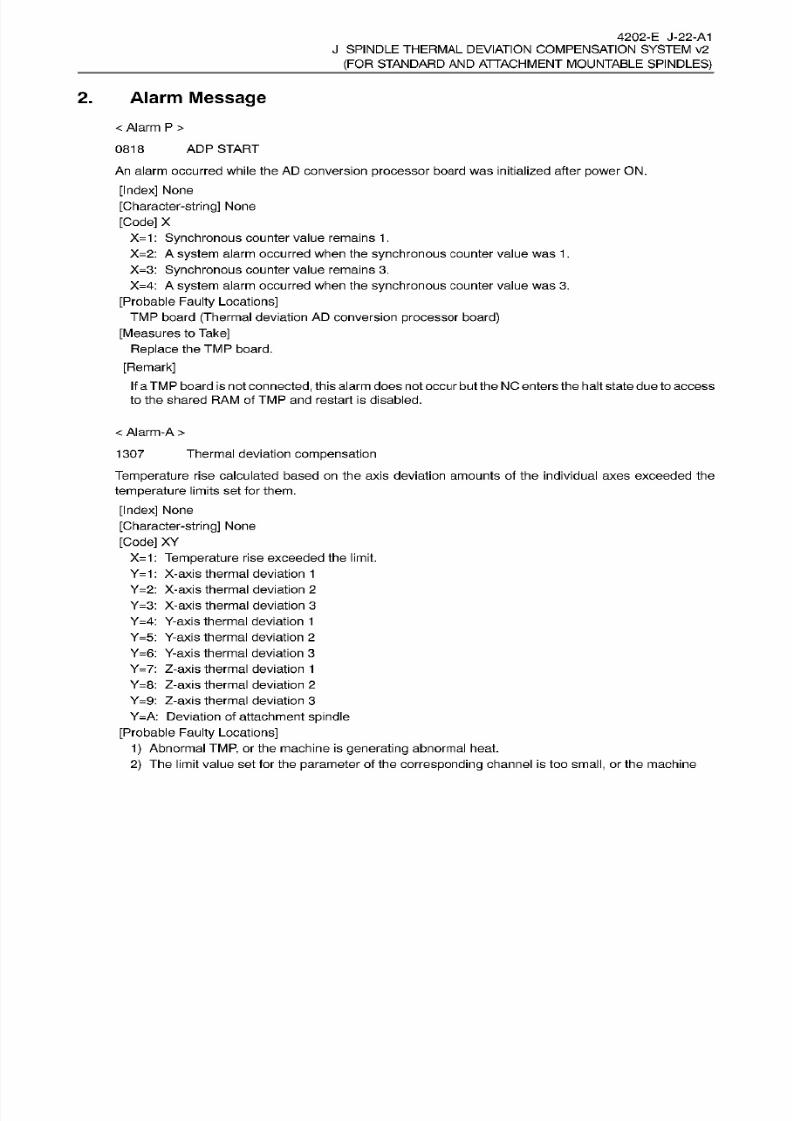
8/15/2019 Okuma Manuals 391
http://slidepdf.com/reader/full/okuma-manuals-391 350/397
4202-E
J-22-A1
J SPINDLE
THERMAL
DEVIATION COMPENSATION SYSTEM v2
(FOR
STANDARD
AND
ATTACHMENT MOUNTABLE
SPINDLES)
2.
Alarm
Message
<
Alarm P
>
AD P
START818
An
alarm
occurred
while
the
AD
conversion
processor
board was initial ized after
power
ON.
[Index]
None
[Character-string] None
[Code]
X
X=1:
Synchronous counter value
remains
1
.
X=2:
A
system
alarm occurred when the
synchronous
counter
value was 1
.
X=3:
Synchronous
counter
value remains
3.
X=4: A
system
alarm
occurred when the
synchronous
counter
value
was
3.
[Probable
Faulty
Locations]
TM P
board
(Thermal deviation AD
conversion processor
board)
[Measures
to Take]
Replace the TM P board.
[Remark]
If
a
TM P board
is not
connected,
this alarmdoesnot
occur
but theNC entersthe halt state due to access
to
the
shared RAM
of
TM P
and restart
is disabled.
<
Alarm-A
>
Thermal deviation
compensation
Temperature
rise calculated based
on the
axis deviation amounts of the individual axes exceeded the
temperature limits
set
for
them.
[Index] None
[Character-string]
None
[Code]
XY
X=1:
Temperature
rise exceeded the limit.
Y=1:
X-axis thermal deviation 1
Y=2:
X-axis thermal
deviation
2
Y=3:
X-axis
thermal deviation 3
Y=4:
Y-axis
thermal deviation 1
Y=5:
Y-axis
thermal deviation
2
Y=6:
Y-axis
thermal deviation 3
Y=7: Z-axis thermal
deviation
1
Y=8: Z-axis thermal deviation
2
Y=9: Z-axis thermal
deviation
3
Y=A:
Deviation of
attachment
spindle
[Probable Faulty Locations]
1)
Abnormal
TMP,
or the
machine
is
generating
abnormal
heat.
2) The limit
value
set
for
the
parameter
of the
corresponding
channel is too
small,
or
the
machine
1307
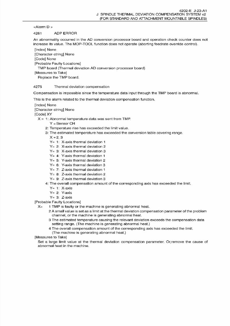
8/15/2019 Okuma Manuals 391
http://slidepdf.com/reader/full/okuma-manuals-391 351/397
4202-E J-23-A1
J SPINDLE
THERMAL
DEVIATION COMPENSATION SYSTEM v2
(FOR
STANDARD
AND
ATTACHMENT MOUNTABLE
SPINDLES)
<Alarm
D
>
AD P
ERROR261
An abnormality
occurred
in the
AD conversion processor board and
operation
check counter does not
increase
its
value. The MOP-TOOL
function
does not
operate
(aborting
feedrate override
control).
[Index]
None
[Character-string]
None
[Code] None
[Probable
Faulty Locations]
TMP
board
(Thermal
deviation AD
conversion
processor
board)
[Measures to
Take]
Replace
the
TM P
board.
Thermal deviation
compensation
Compensation is
impossible since the
temperature
data
input through
the
TMP
board is abnormal.
4275
This
is
the
alarm related to
the
thermal deviation
compensation
function.
[Index]
None
[Character-string]
None
[Code] XY
X
=
1
:
Abnormal
temperature
data was sent
from
TMP.
Y
=
Sensor CH
2:
Temperature
rise has exceeded
the
limit value.
3:
The estimated
temperature
has
exceeded
the conversion
table
covering
range.
X
=2,
3
Y=
1
:
X-axis thermal deviation
1
Y=
2:
X-axis thermal deviation
2
Y=
3:
X-axis thermal deviation
3
Y=
4: Y-axis
thermal
deviation
1
Y= 5:
Y-axis thermal deviation
2
Y=
6:
Y-axis
thermal deviation
3
Y= 7: Z-axis thermal deviation 1
Y= 8:
Z-axis thermal deviation 2
Y= 9:
Z-axis thermal deviation
3
4: The overall
compensation amount of
the
corresponding
axis has exceeded the limit.
Y=
1: X-axis
Y=
2: Y-axis
Y=
3:
Z-axis
[Probable
Faulty
Locations]
X=
1 TM P
is faulty
or
the
machine is
generating
abnormal heat.
2 A
small value
is set as a limit at the
thermal deviation compensation parameter of
the
problem
channel,
or the machine
is
generating
abnormal heat.
3
The
estimated
temperature
causing the relevant deviation exceeds
the
compensation data
setting
range.
(The
machine
is
generating
abnormal
heat.)
4
The overall
compensation amount
of
the corresponding
axis has
exceeded the limit.
(The
machine
is
generating abnormal heat.)
[Measures
to
Take]
Set a
large l imit value
at
the thermal
deviation compensation parameter.
Or,remove the cause
of
abnormal heat
in
the machine.

8/15/2019 Okuma Manuals 391
http://slidepdf.com/reader/full/okuma-manuals-391 352/397
4202-E
J-24-A1
J SPINDLE
THERMAL
DEVIATION COMPENSATION SYSTEM v2
(FOR
STANDARD
AND
ATTACHMENT MOUNTABLE
SPINDLES)
[Related
Specifications]
Thermal deviation
compensation
Thermistor error284
[Index]
None
[Character-string] None
[Code]
Sensor
CH
[Probable
Faulty
Locations]
1)
The corresponding
temperature
sensor is malfunctioning
or its
wiring
is broken.
2)
The
TM P
is
faulty.
[Measures
to Take]
1)
Check
if
the corresponding
temperature
sensor is mounted
correctly.
2)
Replace
the
temperature
sensor.
[Others]
-
The
compensation
amount becomes
“0 ”
for deviation
which
is detected
by
a
malfunctioning sensor.
-
Fo r
sensor
channels
7
and
8
used for
the
attachment
specification,
this alarm
does
not occur.

8/15/2019 Okuma Manuals 391
http://slidepdf.com/reader/full/okuma-manuals-391 353/397
4202-E J-25-A1
J SPINDLE
THERMAL
DEVIATION COMPENSATION SYSTEM v2
(FOR
STANDARD
AND
ATTACHMENT MOUNTABLE
SPINDLES)
3.
Precaution
Regarding
Thermal
Deviation
Compensation
Parameters
NOTICE
: The thermal deviation compensation
parameters
described
on
the following
pages
have
already
been
set
at
Okuma. Do
not
change
these
parameters.
Change of
these
parameters
may
disable normal compensation.
If
you
change
the
parameters
by
mistake, immediately turn off
the
power
and
then
turn
it on .
The
previous parameter
data remains effective unless yo u press the BACKUP
key
after
parameter
change.
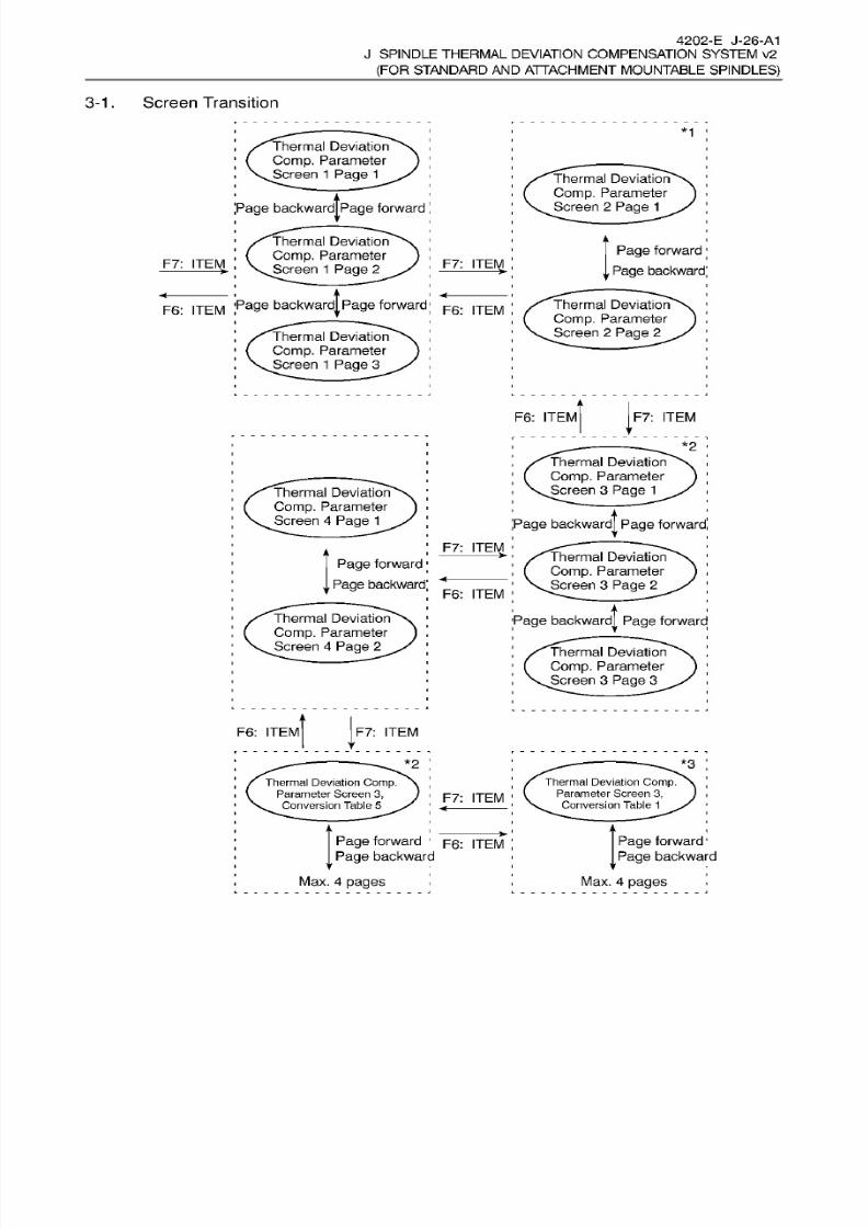
8/15/2019 Okuma Manuals 391
http://slidepdf.com/reader/full/okuma-manuals-391 354/397
4202-E J-26-A1
J
SPINDLE THERMAL DEVIATION COMPENSATION SYSTEM v2
(FOR STANDARD
AN D
ATTACHMENT
MOUNTABLE
SPINDLES)
3-1
. Screen
Transition
*1
Thermal Deviation
Comp.
Parameter
Screen
1 Page 1
Thermal Deviation
Comp. Parameter
Screen 2
Page
1
age
backward|page
forward
Thermal Deviation
Comp. Parameter
Screen
1 Page
2
Page
forward
Page
backward
7:
ITEM F7: ITEM
Page
backwardjpage
forward Thermal Deviation
Comp.
Parameter
Screen
2 Page
2
F6: ITEM F6: ITEM
Thermal
Deviation
Comp.
Parameter
Screen 1
Page
3
F6:
ITEM
F7:
ITEM
*2
Thermal
Deviation
Comp.
Parameter
Screen 3
Page 1
hermal Deviation
Comp.
Parameter
Screen
4 Page
1
Page
backward|
Page
forward
F7:
ITEM
/ Thermal
Deviationÿ-v
;
f
Comp. Parameter
j
\Screen
3
Page 2
;
Page
backward |
Page
forward
>
Page forward
Page backward
F6:
ITEM
Thermal Deviation
Comp.
Parameter
Screen
4 Page
2
Thermal
Deviation
Comp.
Parameter
Screen 3
Page
3
F6 :
ITEM F7:
ITEM
V
*2
*3
Thermal Deviation Comp.
Parameter Screen 3,
Conversion Table
1
Thermal Deviation
Comp.
Parameter Screen
3,
.
Conversion
Table
5
F7:
ITEM
Page
forward
1
F6:
|TEM
Page
backward
Max.
4
pages
Page
forward
1
Page
backward
Max.
4
pages
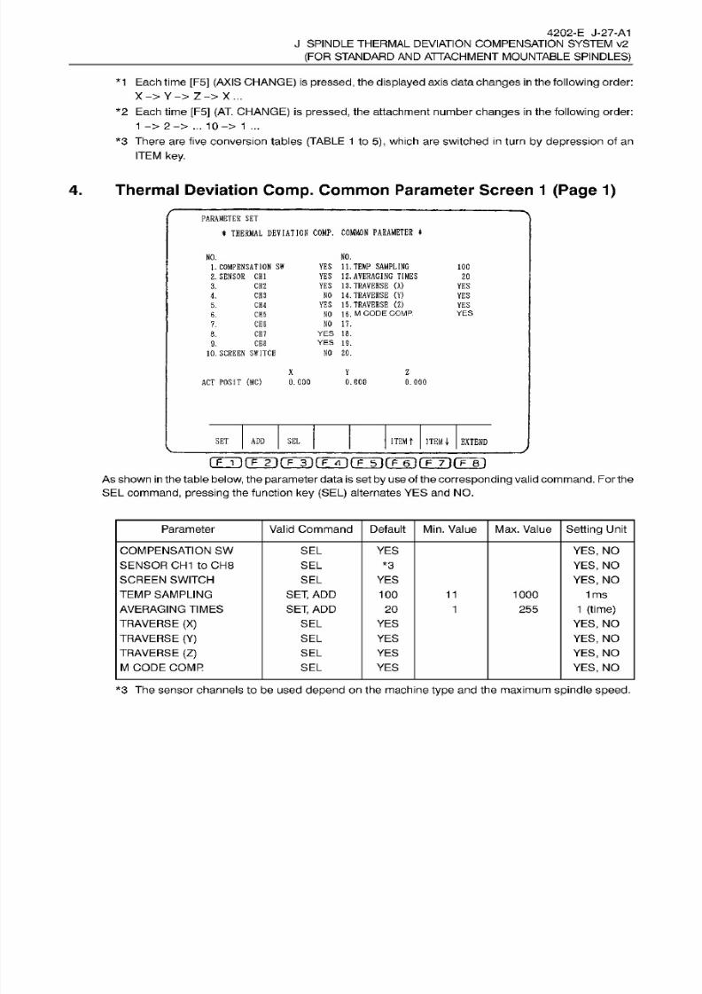
8/15/2019 Okuma Manuals 391
http://slidepdf.com/reader/full/okuma-manuals-391 355/397
4202-E
J-27-A1
J SPINDLE
THERMAL
DEVIATION COMPENSATION SYSTEM v2
(FOR
STANDARD
AND
ATTACHMENT MOUNTABLE
SPINDLES)
*1
Eachtime [F5]
(AXIS CHANGE)
is pressed, the
displayed
axis
data changes in
the
following
order:
X-> Y->
Z->
X...
*2
Each time
[F5] (AT.
CHANGE) is
pressed, the attachment number
changes in
the
following
order:
1
->
2->
...
10->
1 ...
*3
There
are five conversion
tables
(TABLE 1
to 5), which are
switched in
turn
by
depression
of an
ITEM
key.
4.
Thermal
Deviation
Comp.
Common
Parameter Screen
1
(Page
1)
PARAMETER
SE T
*
THERMAL
DEVIATION
COMP.
COMMON PARAMETER
NO.
O.
YES
11.
TEMP SAMPLING
YES
12.
AVERAGING TIMES
YES
13.
TRAVERSE
(X>
NO
14.
TRAVERSE
(Y)
YES
15.
TRAVERSE
<Z)
NO
16.
M
CODE COMP.
NO 17.
YES
18.
YES
19.
NO
20.
1.
COMPENSATION
SN
2.
SENSOR
CHI
100
20
3.
CH2
YES
CH3 YES.
CH4
YE S
.
YES
. CH5
CH6
.
8.
CH7
CHS
.
10.
SCREEN
SNITCH
X Y Z
AC T
POSIT
(MC)
0.000
0.000
0.000
SET
ADD
SE L
ITEM
t
ITEMJ,
EXTEND
gjifÿrrr)nÿnÿrF-6ir?-TifF-r)
As shown in
the table
below,
the
parameter
data
is
set
by use
of the
corresponding
validcommand. Fo r the
SEL
command, pressing the function ke y (SEL)
alternates YES
and NO.
Parameter Valid
Command Default
Min.
Value Max.
Value
Setting
Unit
COMPENSATION SW
SENSOR CH1 to CH8
SCREEN
SWITCH
TEMP
SAMPLING
AVERAGING TIMES
TRAVERSE
(X)
TRAVERSE
(Y)
TRAVERSE
(Z)
M
CODE COMP
SE L
YES YES,
NO
YES,
NO
YES,
NO
1
ms
1
(time)
YES,
NO
YES,
NO
YES, NO
YES,
NO
SE L *3
SEL
YE S
SET,
ADD
SET,
ADD
100
11
1000
20 1
255
SEL YE S
SE L
YES
SEL
YE S
SE L YES
*3
The
sensor
channels
to be
used
depend on the machine type and
the
maximum
spindle speed.
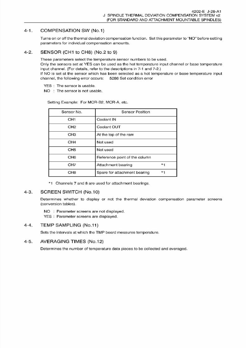
8/15/2019 Okuma Manuals 391
http://slidepdf.com/reader/full/okuma-manuals-391 356/397
4202-E J-28-A1
J SPINDLE
THERMAL
DEVIATION COMPENSATION SYSTEM v2
(FOR
STANDARD
AND
ATTACHMENT MOUNTABLE
SPINDLES)
4-1
. COMPENSATION SW
(No.1)
Turns
on
or off the thermal deviation
compensation
function.
Set
this
parameter
to “NO
before setting
parameters
for individual
compensation
amounts.
4-2.
SENSOR
(CH1
to
CH8)
(No.2
to
9)
These
parameters
select
the
temperature
sensor numbers to be used.
Only the
sensors
set
at
YES
can
be used as the hot
temperature
input channel or base
temperature
input
channel. (For details,
refer
to the
descriptions
in
7-1 and 7-2.)
If NO is
set at
the sensor which has been selected as
a
ho t
temperature
or base
temperature input
channel,
the
following
error occurs:
5286
Set
condition error
YE S : Th e sensor is usable.
NO
:
The sensor is
not
usable.
Setting
Example:
For
MCR-B2, MCR-A,
etc.
Sensor No. Sensor
Position
CH 1 Coolant
IN
CH2 Coolant OUT
CH3 At the
top
of the ram
CH 4
Not
used
CH5 Not used
CH6 Reference
point
of
the
column
CH 7
Attachment
bearing *1
CH 8
Spare
for attachment
bearing *1
*1
Channels 7 and
8
are used for attachment
bearings.
4-3.
SCREEN SWITCH
(No.
10)
Determines whether to
display
or
not the
thermal deviation compensation parameter
screens
(conversion tables).
NO
:
Parameter screens are not
displayed.
YES
:
Parameter
screens
are
displayed.
4-4. TEMP
SAMPLING
(No.11)
Sets
the intervals at which
the
TMP
board measures
temperature.
4-5. AVERAGING TIMES
(No.12)
Determines the number of
temperature
data
pieces
to be collected and
averaged.
8/15/2019 Okuma Manuals 391
http://slidepdf.com/reader/full/okuma-manuals-391 357/397
4202-E J-29-A1
J SPINDLE
THERMAL
DEVIATION COMPENSATION SYSTEM v2
(FOR
STANDARD
AND
ATTACHMENT MOUNTABLE
SPINDLES)
4-6. TRAVERSE
(X), (Y), (Z)
(No.
13
to
15)
The thermal deviation
compensation
data
in the
servo
processor is
updated
at
the time of
X-
(Y-
or
Z-)
axis movement
in
AUTO or
MDI
mode or at
intervals
(10
seconds)
for
compensating
thermal
deviation.
This
parameter
chooses the
update
timing.
YES : The
compensation
amount is
updated
when
X-(Y-
or
Z-)
axis
is moved
(by
rapid
traverse
or
cutting
feed) in
AUTO or
MDI
mode.
NO
:
The
compensation
amount
is updated
every
10
seconds
(thermal
deviation
compensation
interval).
4-7.
M
CODE
COMP.
(NO.16)
This
parameter
m akes “M 297” code valid. T his code
specifies
updating
of the thermal deviation
compensation
amount to
be
sent to the servo
processor
even during machining
that is no t
associated
with axis movements.
M297 updates
the
compensation
amount
only
w hen the setting
for
No .
13/14/15
“TRAVERSE
(X)/(Y)/(Z)”
is
“YES” with
the setting
for
this
parameter
“YES”.
YE S
:
Updating of the
compensation
amount,
specified
by
M297, is
valid.
NO : Updating
of the
compensation amount, specified
by
M297,
is invalid.
Note: If
the
setting
for
this
parameter
is “NO”,
compensation
amount is not
updatedevenifM297
is
specified.
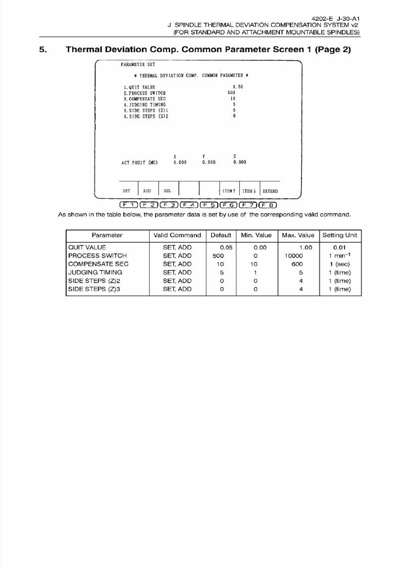
8/15/2019 Okuma Manuals 391
http://slidepdf.com/reader/full/okuma-manuals-391 358/397
4202-E J-30-A1
J
SPINDLE THERMAL DEVIATION COMPENSATION SYSTEM v2
(FOR STANDARD
AN D
ATTACHMENT
MOUNTABLE
SPINDLES)
5. Thermal Deviation
Comp.
Common
Parameter Screen
1 (Page
2)
PARAMETER
SE T
*
THERMAL
DEVIATION
COMP.
COMMON
PARAMETER
*
0.
50
.
QUIT
VALUE
2.
PROCESS
SWITCH
3.
COMPENSATE
SEC
L JUDGING
TIMING
5. SIDE
STEPS
(Z)l
6. SIDE STEPS
(Z)2
50 0
10
5
0
0
Y
Z
0.
000
CT POSIT
(MC)
0.000
0.000
ITEM
t
ITEM
|
EXTEND
ET
ADD
SE L
As
shown
in
the table
below,
the parameter data
is
set
by
use
of
the
corresponding
valid command.
Parameter
Valid
Command Default
Min.
Value
Max. Value
Setting
Unit
QUIT
VALUE
PROCESS SWITCH
COMPENSATE
SE C
JUDGING TIMING
SIDE
STEPS
(Z)2
SIDE
STEPS
(Z)3
SET,
AD D
SET, AD D
SET,
AD D
SET,
AD D
SET,
AD D
SET,
AD D
0.05 0.00 1.00
0.01
1 min-1
1
(sec)
1 (time)
1
(time)
1 (time)
500 0
10000
10
10
600
1
5
O 0 4
O
0
4
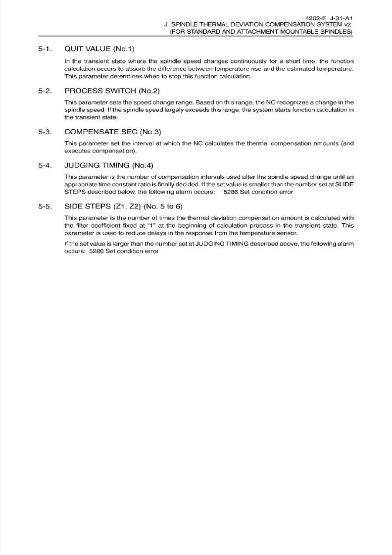
8/15/2019 Okuma Manuals 391
http://slidepdf.com/reader/full/okuma-manuals-391 359/397
4202-E J-31-A1
J SPINDLE
THERMAL
DEVIATION COMPENSATION SYSTEM v2
(FOR
STANDARD
AND
ATTACHMENT MOUNTABLE
SPINDLES)
5-1.
QUIT
VALUE
(No.1)
In
the transient state where the
spindle
speed changes
continuously
for
a short
time,
the function
calculation
occurs
to absorb
the
difference between
temperature
rise and
the
estimated
temperature.
This
parameter
determines
when to
stop
this
function calculation.
5-2.
PROCESS SWITCH (No.2)
This parameter
sets
the speed
change
range.
Based
on
this
range,
the NC
recognizes
a
change
in the
spindle speed.
If
the
spindle
speed largely
exceeds this range,
the
system
starts
function calculation in
the transient
state.
5-3. COMPENSATE SEC
(No.3)
This
parameter
set the interval
at
which the NC calculates the thermal
compensation
amounts (and
executes
compensation).
5-4.
JUDGING TIMING
(No.4)
This
parameter
is the number
of
compensation
intervals used after the
spindle speed change
until an
appropriate
time
constant
ratio is
finally
decided.
If
the set
value
is
smaller than the number set at SLIDE
STEPS described
below,
the following
alarm
occurs:
5286 Set condition error
5-5. SIDE STEPS
(Z1 , Z2)
(No.
5 to
6)
This
parameter
is
the number of times the thermal
deviation compensation
amount
is
calculated
with
the filter
coefficient
fixed at
“1”
at the
beginning
of calculation
process
in
the transient state.
This
parameter
is
used
to reduce
delays
in the
response
from the temperature
sensor.
If
the
set value
is
larger
than the number
set at
JUDGING TIMING described
above,
the
following alarm
occurs:
5286
Set
condition error

8/15/2019 Okuma Manuals 391
http://slidepdf.com/reader/full/okuma-manuals-391 360/397
4202-E J-32-A1
J SPINDLE
THERMAL
DEVIATION COMPENSATION SYSTEM v2
(FOR
STANDARD
AND
ATTACHMENT MOUNTABLE
SPINDLES)
6.
Thermal
Deviation
Comp.
Common
Parameter Screen
1
(Page 3)
PARAMETER SET
*
THERMAL
DEVIATION COMP.
COMMON PARAMETER
*
7. OVERALL LIMIT
(X)
8. OVERALL
LIMIT
(Y)
9.
OVERALL
LIMIT
(Z)
999
999
999
Y
Z
ACT POSIT
(MC)
0.000
0.000
0. 000
ITEM
t
ITEM EXTEND
ET
ADD
SE L
[TÿfTÿrrT)(TÿrrTirF~6~irp~TirF~ei
As shown
in
the table
below,
the
parameter
data
is
set
by
use
of
the
corresponding
valid command.
Parameter Valid Command Default
Min.
Value Max. Value
Setting
Unit
OVERALL
LIMIT
(X)
OVERALL
LIMIT
(Y)
OVERALL
LIMIT
(Z)
SET,
AD D
SET,
ADD
SET,
ADD
999 0 9999
9999
9999
1
1
|.im
1
pm
999
0
999
0
OVERALL
LIMIT (X), (Y),
(Z)
(NO.
7 to
9)
-1.
This
parameter
sets the limit value of the
compensation
amount for the
corresponding
axis.
If
the overall
compensation
amount
including
the
deviation
of tool edge
position
exceeds
the set
limit
value,
the overall
compensation
amount
is
replaced
with the
limit
value
set
for
this
parameter.
The
set
value is
treated as an
absolute
value.
If
this
replacement occurs,
the
following alarm occurs:
Alarm
D
4275
Thermal
deviation compensation.
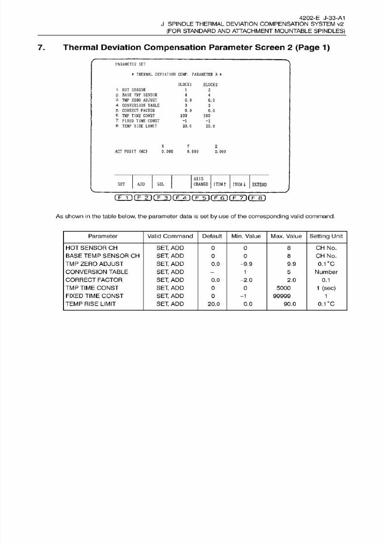
8/15/2019 Okuma Manuals 391
http://slidepdf.com/reader/full/okuma-manuals-391 361/397
4202-E J-33-A1
J
SPINDLE THERMAL DEVIATION COMPENSATION SYSTEM v2
(FOR STANDARD
AN D
ATTACHMENT
MOUNTABLE
SPINDLES)
7.
Thermal Deviation
Compensation
Parameter Screen
2 (Page 1)
PARAMETER
SET
*
THERMAL
DEVIATION
COMP.
PARAMETER X
*
BLOCK]
BLOCK
2
1.
HO T SENSOR
2.
BASE
TMP SENSOR
3.
TMP ZERO ADJUST
4
CONVERSION
TABLE
5
CORRECT
FACTOR
6.
TM P
TIME
CONST
7.
FIXED
TIME
CONST
8.
TEMP
RISE
LIMIT
1
2
4
4
0. 0
0.0
3
3
0.0 0.0
100
100
-1
-1
20.0
20.0
X
Y
Z
ACT POSIT
(MC)
0.000 0.000
0.
000
AXIS
SE L
CHANGE
ITEM
T
ITEM
4-
EXTEND
ET
ADD
(TTÿrrrirrTiiTÿrrÿrFÿrFTirrB'i
As
shown
in
the table
below,
the parameter data
is
set
by
use
of the corresponding
valid
command.
Parameter
Valid
Command Default
Min.
Value
Max. Value
Setting
Unit
HOT SENSOR CH
BASE
TEMP
SENSOR CH
TM P
ZERO
ADJUST
CONVERSION
TABLE
CORRECT
FACTOR
TMP TIME
CONST
FIXED TIME
CONST
TEMP
RISE
LIMIT
SET,
AD D
SET, AD D
SET,
AD D
SET,
AD D
SET,
AD D
SET,
AD D
SET,
AD D
SET,
AD D
CH
No.
CH
No.
0.1 'C
Number
O
0 8
0
0 8
0.0
-9.9
9.9
1
5
0.0
-2.0 2.0 0.1
1
(sec)
0
5000
99999
-1 1
0.1 c
0.0
0.0 90.0
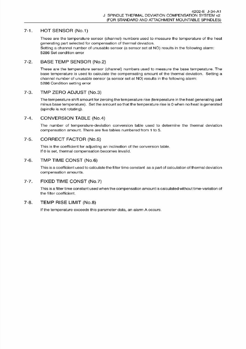
8/15/2019 Okuma Manuals 391
http://slidepdf.com/reader/full/okuma-manuals-391 362/397
4202-E J-34-A1
J SPINDLE
THERMAL
DEVIATION COMPENSATION SYSTEM v2
(FOR
STANDARD
AND
ATTACHMENT MOUNTABLE
SPINDLES)
HOT
SENSOR
(No.1)-1.
These are the
temperature
sensor
(channel)
numbers used to
measure
the
temperature
of the heat
generating
part
selected for
compensation
of
thermal
deviation.
Setting
a channel number of unusable sensor
(a
sensor set at
NO)
results in
the following alarm:
5286
Se t
condition
error
7-2.
BASE
TEMP
SENSOR (No.2)
These
are
the
temperature
sensor (channel) numbers used to
measure
the base
temperature.
The
base temperature is used
to
calculate the
compensating
amount of
the thermal deviation. Setting
a
channel number of unusable sensor
(a
sensor set at
NO)
results
in
the
following
alarm:
5286
Condition
setting
error
7-3.
TMP ZERO
ADJUST
(No.3)
The
temperature
shift amount for
zeroing
the
temperature
rise (temperature
in
the heat
generating part
minus
base temperature).
Set the amount so that the
temperature
rise
is
0
when no heat is
generated
(spindle
is not
rotating).
CONVERSION TABLE (No.4)
-4.
The number of temperature-deviat ion conversion table
used
to determine the thermal deviation
compensation
amount. There are
five
tables
numbered
from
1 to
5.
CORRECT
FACTOR
(No.5)
This is
the coefficient for
adjusting
an
inclination of the conversion
table.
If
0 is set,
thermal
compensation
becomes
invalid.
7-5.
7-6.
TMP
TIME
CONST
(No.6)
This is
a
coefficient used to calculate the filter
time
constant as
a
part
of calculation of thermaldeviation
compensation
amounts.
FIXED
TIME
CONST
(No.7)
-7.
This
is
a filter time constant used when the
compensation
amount is
calculated withouttime-variation of
the filter coefficient.
7-8. TEMP RISE
LIMIT
(No.8)
If the temperature exceeds this
parameter
data,
an alarm A occurs.
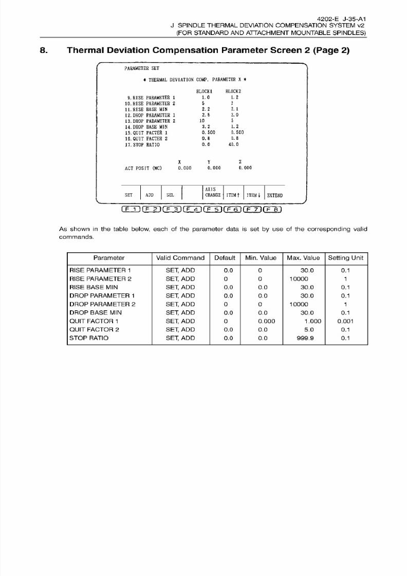
8/15/2019 Okuma Manuals 391
http://slidepdf.com/reader/full/okuma-manuals-391 363/397
4202-E J-35-A1
J
SPINDLE THERMAL DEVIATION COMPENSATION SYSTEM v2
(FOR STANDARD
AN D
ATTACHMENT
MOUNTABLE
SPINDLES)
8. Thermal Deviation
Compensation
Parameter Screen
2 (Page
2)
PARAMETER
SE T
*
THERMAL
DEVIATION
COMP.
PARAMETER
X
*
BLOCK
1
BLOCK
2
i.
0
1. 2
. RISE
PARAMETER
1
10. RISE
PARAMETER
2
11.
RISE BASE
MI N
12.
DROP
PARAMETER
1
13. DROP
PARAMETER
2
14.
DROP
BASE MIN
15.
QUIT
FACTER
1
16.
QUIT
FACTER
2
17.
STOP RATIO
5
2
2.2
2.1
2.0
.
5
5
0
1.2
.
2
0. 500
. 50 0
0.8
.8
40.0.0
1
Y
AC T
POSIT
(MC)
0.000
.000
.000
AXIS
SE L
CHANGE
ITEM
T
ITEM
\
EXTEND
ET
ADD
rÿ(Tÿrr3ifrrn(T3i(TÿrFÿ-irr6T
A s show n
in the table below, each of
the parameter data
is
set
by
use
of
the
corresponding
valid
commands.
Parameter
Valid
Command Default
Min.
Value
Max.
Value
Setting
Unit
RISE
PARAMETER 1
RISE
PARAMETER 2
RISE
BASE MIN
DROP
PARAMETER 1
DROP
PARAMETER 2
DROP
BASE
MIN
QUIT
FACTOR
1
QUIT
FACTOR
2
STOP
RATIO
SET,
AD D
SET,
AD D
SET,
AD D
SET,
AD D
SET,
AD D
SET,
AD D
SET,
AD D
SET,
AD D
SET,
AD D
0.0 0 30.0 0.1
0
10000
1
0.0
0.0 30.0 0.1
0.1
.0
0.0
30.0
0 0 10000 1
0.0 0.0 30.0
0.1
0
0.000 1.000 0.001
0.0
0.0 5.0 0.1
0.0 0.0 999.9
0.1

8/15/2019 Okuma Manuals 391
http://slidepdf.com/reader/full/okuma-manuals-391 364/397
4202-E J-36-A1
J SPINDLE
THERMAL
DEVIATION COMPENSATION SYSTEM v2
(FOR
STANDARD
AND
ATTACHMENT MOUNTABLE
SPINDLES)
8-1
. RISE
PARAMETER 1
,
RISE
PARAMETER 2,
RISE
BASE
MIN
(No.
9 to
11)
These
are
the
coefficients
used to determine the
appropriate
time
constant
ratio for
temperature
rise.
DROP
PARAMETER
1,
DROP
PARAMETER
2,
DROP BASE
MIN
(No.12to
14)
These are the
coefficients
used
to
determine the appropriate time
constant
ratio for temperature drop.
8-2.
8-3.
QUIT FACTOR
1
,
QUIT
FACTOR
2
(No.
15,
16)
These
are the coefficients
used to calculate the value for
stopping
calculation of the filter coefficient.
If
the
filter coefficient becomes smaller than the value calculated f rom these
values,
the
system stops
calculating
the
change
of
filter coefficient.
8-4.
STOP
RATIO (NO.
1
7)
This
is
a
factor
used
to
determine the
appropriate
time
constant
ratio for
stopping
the
spindle.
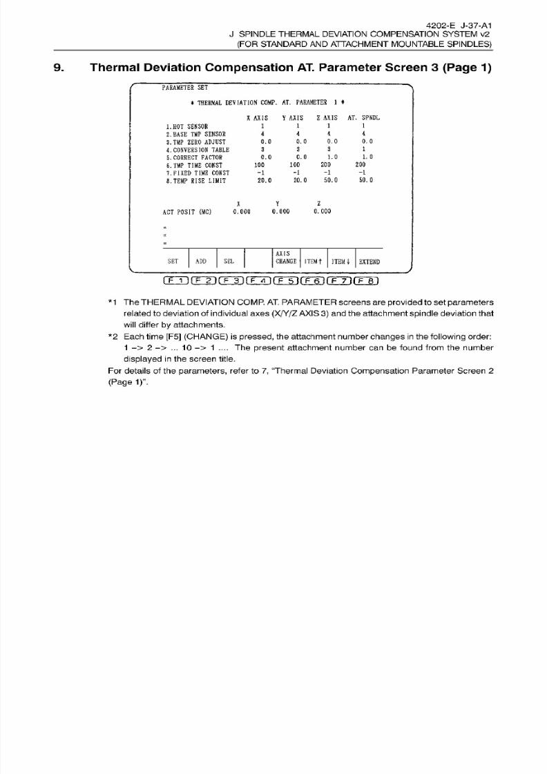
8/15/2019 Okuma Manuals 391
http://slidepdf.com/reader/full/okuma-manuals-391 365/397
4202-E J-37-A1
J SPINDLE
THERMAL
DEVIATION COMPENSATION SYSTEM v2
(FOR
STANDARD
AND
ATTACHMENT MOUNTABLE
SPINDLES)
9. Thermal
Deviation
Compensation
AT.
Parameter Screen 3
(Page
1)
PARAMETER
SET
*
THERMAL
DEVIATION
COMP.
AT .
PARAMETER 1
*
X
AXIS
Y
AXIS
Z AXIS AT.
SPNDL
1 1
1
1.
HOT
SENSOR
2.
BASE
TMP
SENSOR
3.TMP
ZERO
ADJUST
4. CONVERSION
TABLE
5.
CORRECT FACTOR
6.
TMP
TIME CONST
7. FIXED TIME
CONST
8.
TEMP
RISE
LIMIT
1
4
4
i
0.0
0.0
0.0
.0
1
3
3
1. 0
.0
1.0
.0
200
20 0
00
100
-1
-1 -1
1
50.0
0.
0 50.
0
0.0
Z
Y
0.000
CT POSIT
(MC) 0.000
.000
AXIS
CHANGE
ITEMt
ITEM
i
EXTEND
ET
ADD
SE L
(TTi r rÿrrÿrrTn(T3i rFÿ i rFÿnrFÿ i
*1 The THERMAL DEVIATION COMP. AT.
PARAMETER
screens are provided toset
parameters
related to deviation of individual
axes (X/Y/Z AXIS
3)
and the attachment
spindle
deviation that
will
differ
by attachments.
*2
Each
time
[F5]
(CHANGE)
is pressed,
the attachment
number
changes
in
the
following order:
1
->
2
->
...
10
->
1
....
Th e present
attachment number can be found from the number
displayed
in
the
screen title.
For details of the
parameters,
refer
to
7,
“Thermal Deviation
Compensation
Parameter Screen
2
(Page 1)”.
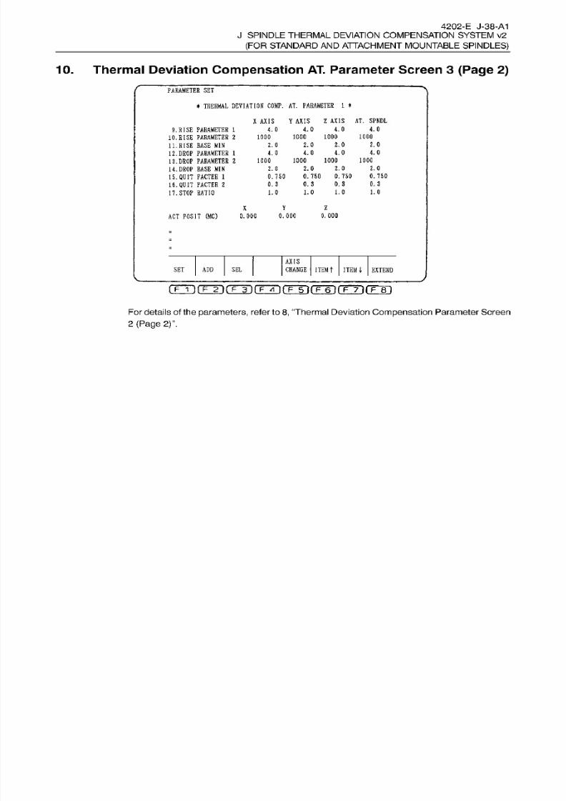
8/15/2019 Okuma Manuals 391
http://slidepdf.com/reader/full/okuma-manuals-391 366/397
4202-E J-38-A1
J
SPINDLE THERMAL DEVIATION COMPENSATION SYSTEM v2
(FOR STANDARD
AN D
ATTACHMENT
MOUNTABLE
SPINDLES)
10. Thermal Deviation
Compensation
AT.
Parameter Screen 3
(Page
2)
PARAMETER
SE T
*
THERMAL
DEVIATION
COMP.
AT . PARAMETER
1
*
X
AXIS
Y
AXIS
Z
AXIS
AT .
SPNDL
4.0
4.0
.0
4.0
.RISE
PARAMETER
1
10. RISE
PARAMETER 2
11.
RISE
BASE
MIN
12. DROP PARAMETER
1
13.
DROP PARAMETER
2
14.
DROP
BASE
MI N
15.
QUIT FACTER
1
16.
QUIT
FACTER
2
17. STOP
RATIO
1000 1000
000
1000
2.0 2.0
.0 2.0
4.0
.0 4.0
.0
1000
000
1000
000
2.0
.0
2.0
.0
0. 750
0.750 0. 750 0.750
0. 3
0.3
0.
3
.3
1.0
1.0
1.0
.0
Y l
ACT
POSIT
(MC)
0.000
0.000
.000
AXIS
CHANGE
ITEM
t
ITEM
I
EXTEND
ET ADD
SE L
[
P
IMF
2)(
F
3
) j
F
For
details of
the
parameters,
refer
to
8,
“Thermal
Deviation
Compensation
Parameter
Screen
2
(Page
2)”.
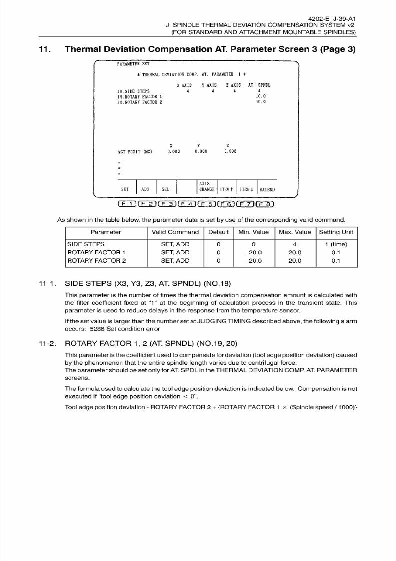
8/15/2019 Okuma Manuals 391
http://slidepdf.com/reader/full/okuma-manuals-391 367/397
4202-E J-39-A1
J SPINDLE
THERMAL
DEVIATION COMPENSATION SYSTEM v2
(FOR
STANDARD
AND
ATTACHMENT MOUNTABLE
SPINDLES)
11
.
Thermal
Deviation
Compensation
AT.
Parameter Screen 3
(Page 3)
PARAMETER
SET
*
THERMAL DEVIATION
COMP.
AT. PARAMETER 1
*
X
AXIS Y AXIS
Z
AXIS
AT . SPNDL
4
4
8. SIDE
STEPS
19 .
ROTARY
FACTOR
1
20.
ROTARY
FACTOR
2
4
4
10.
0
10.0
Y
z
0.000
0.000
CT POSIT
(MC)
0.000
AXIS
CHANGE ITEM
t
ITEM
I
EXTEND
ET
ADD
SE L
(Tÿrrÿrrr i rrTn(TÿiT~6~irFÿ-i rF~ri
As shown
in
the table
below,
the
parameter data
is
set
by
use
of the
corresponding
valid command.
Parameter
Valid
Command
Default
Min.
Value Max. Value Setting
Unit
SIDE STEPS
ROTARY
FACTOR
1
ROTARY
FACTOR
2
SET, ADD
SET, AD D
SET,
AD D
1 (time)
0
4
0
-20.0
-20.0
20.0 0.1
0
20.0
0.1
11-1.
SIDE STEPS (X3, Y3,
Z3,
AT.
SPNDL) (NO.
18)
This parameter
is
the
number of times
the
thermal deviation
compensation
amount is calculated with
the filter
coefficient fixed at
“1”
at
the
beginning
of
calculation
process
in
the
transient state.
This
parameter
is used
to
reduce delays in the
response
from
the
temperature
sensor.
If the
set
value
is
larger
than
the number
set
at JUDGINGTIMING described
above,
the
following
alarm
occurs:
5286
Se t condition
error
11-2.
ROTARY FACTOR
1
,
2
(AT.
SPNDL) (NO.
19,
20)
This parameter is
the
coefficient used
to
compensate
for
deviation (tool
edge
position deviation)
caused
by
the
phenomenon
that the entire
spindle
length
varies due to
centrifugal
force.
The
parameter
should
be
set
only
for
AT.
SPDL
in
the
THERMAL
DEVIATION COMP.
AT.
PARAMETER
screens.
The
formula used
to
calculate the
tool
edge position
deviation
is
indicated below.
Compensation
is
not
executed if
“tool edge
position
deviation
<
0”.
Tool
edge
position
deviation
-
ROTARY FACTOR
2
+
{ROTARY
FACTOR
1
x (Spindle
speed
/
1000)}
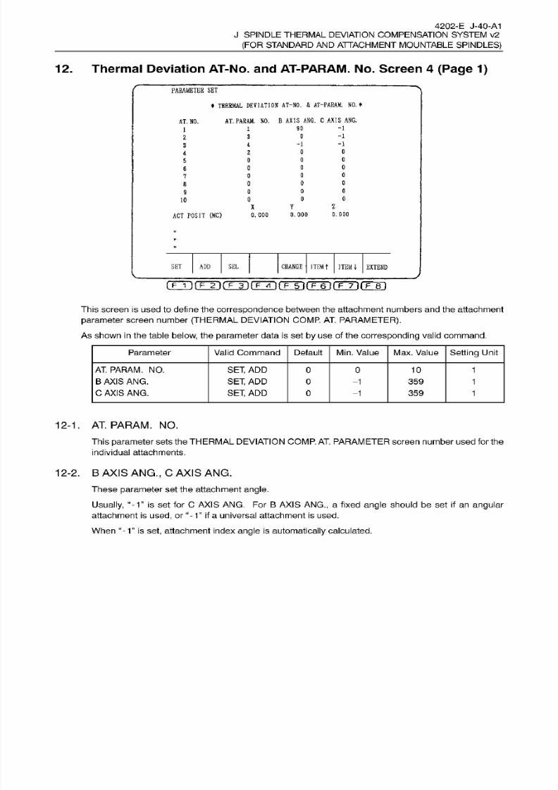
8/15/2019 Okuma Manuals 391
http://slidepdf.com/reader/full/okuma-manuals-391 368/397
4202-E J-40-A1
J SPINDLE
THERMAL
DEVIATION COMPENSATION SYSTEM v2
(FOR
STANDARD
AND
ATTACHMENT MOUNTABLE
SPINDLES)
12.
Thermal
Deviation
AT-No. and
AT-PARAM.
No.
Screen
4
(Page 1)
PARAMETER
SET
*
THERMAL
DEVIATION
AT-NO. & AT-PARAM.
NO.*
AT.PARAM.
NO.
B
AXIS
ANG.
C
AXIS
ANG.
AT .
NO.
90
-1
-1
-1
-1
0
0
0c
0
0
0
0
0
0
Y
Z
0.000
.000
CT
POSIT
(MC)
0. 00 0
CHANGE
ITEMt
ITEM
4
EXTEND
ET
ADD
SE L
rp~TTfF~in(T~T)rFTH(TÿrF~irirF~Ti(Tir)
This
screen is
used
to define the
correspondence
between
the
attachment numbers and the attachment
parameter
screen number
(THERMAL
DEVIATION COMP.
AT.
PARAMETER).
As shown in the table below, the
parameter
data is set by use of the
corresponding
valid command.
Parameter Valid Command Default
Min.
Value Max. Value
Setting
Unit
AT. PARAM.
NO.
B
AXIS
ANG.
C AXIS ANG.
SET, ADD
SET, ADD
SET,
AD D
0 0 10
1
0
-1
359
1
0
-1
359
1
12-1. AT.PARAM. NO.
This
parameter
sets
the THERMAL
DEVIATION COMP.
AT. PARAMETER screen
number used
for the
individual attachments.
12-2. BAXIS
ANG.,
C AX IS
ANG.
These
parameter set
the
attachment
angle.
Usually,
“
-
T
is set for C
AXIS
ANG. For
B
AXIS
ANG.,
a fixed
angle
should be set
if
an
angular
attachment is
used, or
1” if
a universal
attachment
is used.
When
“
- 1 is
set,
at tachment index
angle
is
automatically
calculated.
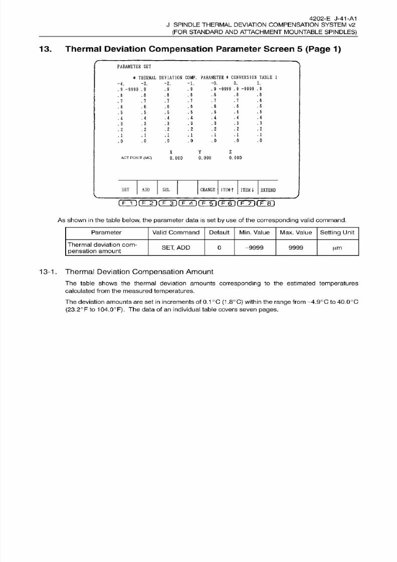
8/15/2019 Okuma Manuals 391
http://slidepdf.com/reader/full/okuma-manuals-391 369/397
4202-E
J-41-A1
J
SPINDLE THERMAL DEVIATION COMPENSATION SYSTEM v2
(FOR STANDARD
AN D
ATTACHMENT
MOUNTABLE
SPINDLES)
13.
Thermal Deviation
Compensation
Parameter Screen
5 (Page 1)
PARAMETER
SET
*
THERMAL
DEVIATION
COMP.
PARAMETER
*
CONVERSION
TABLE 1
1.
0.
0.
2.
-1.
3.
4.
.9 -9999
.9 -9999 .9
9
9 -9999 .9
.9
.8 .8
.8
8
.
8
8
8
.6
7 .7
7
.7
7
7
.6
.6
6
6
.6
6
6
.5
5
.5
5
.
5
55
.4
.4
4
.4
4
4
4
.3
.
3
3
3 .
3
3
3
.
2
2
.2
2
. 2
2
2
.1
. 1
1
1
. 1
1
1
.0
0
.0
0
.0
0
0
Y l
0.000
.
oco
0.000
CT
POSIT
(MC)
CHANGE
ITEM
T
ITEM
4-
EXTEND
ET ADD SE L
[
p
T){F
2)(
F
3
) j
F
As
shown
in
the table
below,
the
parameter
data is set
by
use
of
the
corresponding
valid
command.
Parameter
Valid Command
Default
Min.
Value
Max.
Value
Setting
Unit
Thermal
deviation com¬
pensation
amount
SET,
AD D 0
9999 9999
|im
13-1.
Thermal Deviation
Compensation
Amount
T he table
shows
the thermal
deviation
amounts
corresponding to
the estimated temperatures
calculated
from the
measured
temperatures.
The deviation amounts
are set
in
increments of 0.1°C
(1
,8°C)
within the
range
from
-4-.9°C to
40.0°C
(23.2°F
to
104.0°F).
The data
of
an individual
table
covers
seven
pages.

8/15/2019 Okuma Manuals 391
http://slidepdf.com/reader/full/okuma-manuals-391 370/397
K.
READ/WRITE
AND
GET/PUT
FUNCTIONS
(WITH
FILE
INPUT/OUTPUT
FUNCTION)

8/15/2019 Okuma Manuals 391
http://slidepdf.com/reader/full/okuma-manuals-391 371/397
4202-E
K-1
K.
READ/WRITE
AN D
GET/PUT
FUNCTIONS
(WITH
FILE
INPUT/OUTPUT
FUNCTION)
SECTION
1
GENERAL
Through
the communications of data
(input:
numeric data only,
output:
numeric or character data)
with
an
external
device, the
function
allows
the setting of variables
(common, local,
and system
variables) by
the
host
computer,
the output
of
data
to
a
printer,
etc.
The
file input/output
function reads a data f ile from a sector device
(MD1
,
FDO, FD1
,
FD2,
FD3), writes
arbitrary
data (result of
calculation,
alphabet, etc.) to a
file,
and
creates
a
new
file.
Up to two
files
can be read and
writing
is
possible
to
one
file.
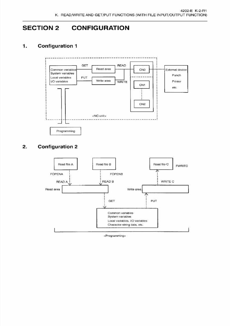
8/15/2019 Okuma Manuals 391
http://slidepdf.com/reader/full/okuma-manuals-391 372/397
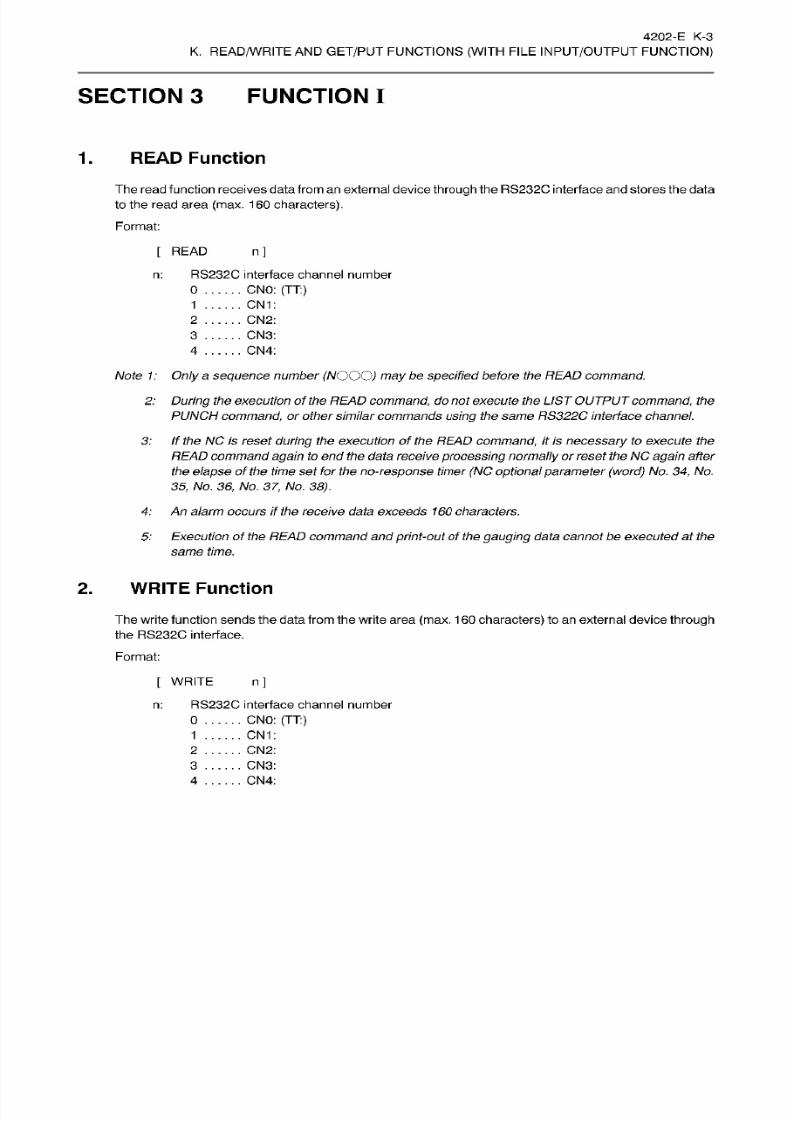
8/15/2019 Okuma Manuals 391
http://slidepdf.com/reader/full/okuma-manuals-391 373/397
4202-E K-3
K.
READ/WRITE
AN D
GET/PUT
FUNCTIONS
(WITH
FILE
INPUT/OUTPUT
FUNCTION)
SECTION 3 FUNCTION
I
1.
READ
Function
The read function receives data from an
external device
through
the
RS232C
interface and
stores
the data
to the read
area
(max.
160
characters).
Format:
[
READ
n]
RS232C interface channel number
:
CNO: (TT:)
CN1
CN2
CN3
CN4
Note
1:
Only a
sequence
number
(NOOO)
may
be
specified
before
the READ command.
2: During
the
execution of the READ
command,
do not
execute
the
LISTOUTPUT
command,
the
PUNCH
command,
or othersimilarcommands using the same
RS322C
interface channel.
3:
if
the
NO
is
reset during
the
execution of the READ
command,
it
is necessary to
execute
the
READ commandagain
to
end the data receiveprocessingnormally or reset the
NC
again
after
the
elapse
of the time set for the no-response timer
(NC optional
parameter
(word) No. 34, No.
35 , No .
36,
No .
37, No.
38).
4:
An
alarm
occurs
if the
receive
data exceeds
1
60
characters.
5:
Executionof the READ commandand
print-out
of
the gauging data cannot be executedat the
same
time.
2.
WRITE
Function
The write function sends the data from the write area (max.
1
60
characters)
to an external device
through
the
RS232C
interface.
Format:
[
WRITE n]
RS232C
interface channel number:
0 CNO:
(TT:)
CN1
CN2
CN3
CN4
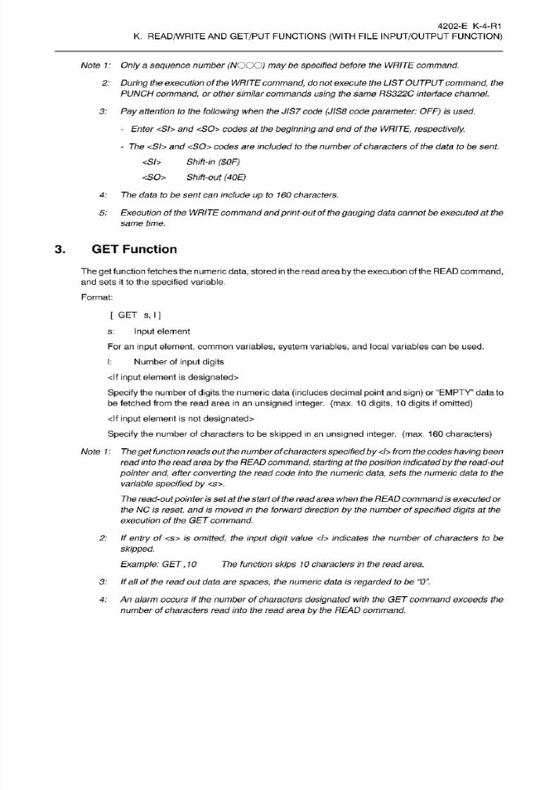
8/15/2019 Okuma Manuals 391
http://slidepdf.com/reader/full/okuma-manuals-391 374/397
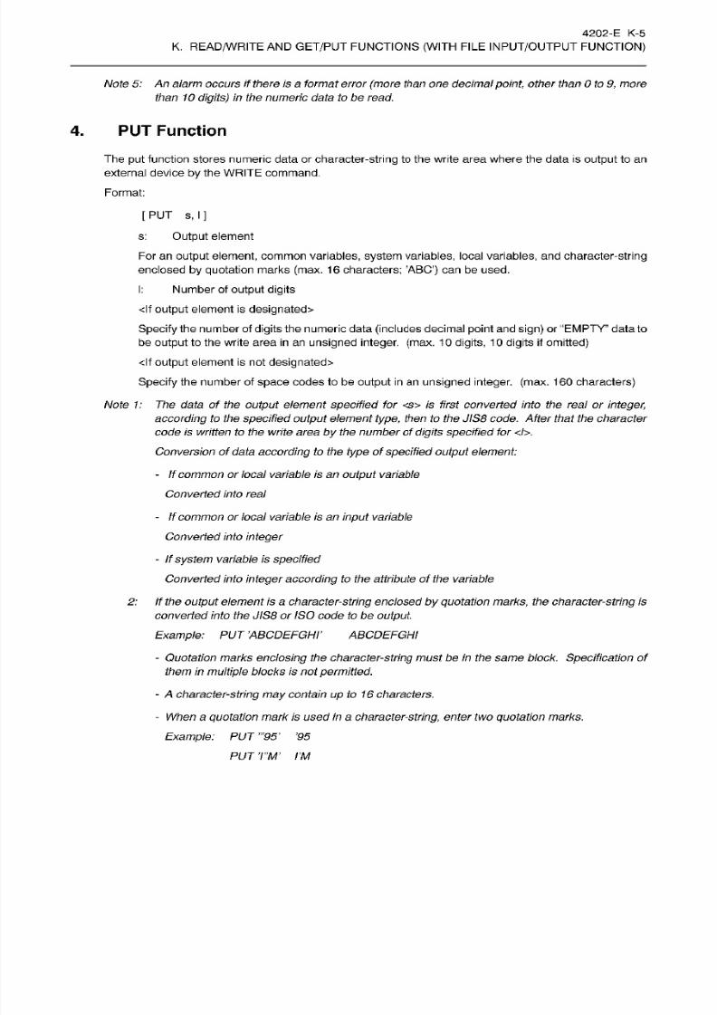
8/15/2019 Okuma Manuals 391
http://slidepdf.com/reader/full/okuma-manuals-391 375/397
4202-E K-5
K.
READ/WRITE
AN D
GET/PUT
FUNCTIONS
(WITH
FILE
INPUT/OUTPUT
FUNCTION)
Note
5:
An
alarm
occurs
if
there is a format
error
(more than
one
decimal
point,
other than 0 to
9,
more
than
10
digits) in
the
numeric data to
be
read.
4.
PUT Function
The
put
function
stores
numeric
data
or
character-string
to
the write area where
the
data
is
output
to
an
external
device by the WRITE
command.
Format:
[PUT s, I ]
s:
Output element
For
an
output
element,
common
variables,
system
variables,
local
variables,
and
character-string
enclosed
by
quotation
marks
(max.
16
characters:
’ABC’) can be
used.
I:
Number of
output digits
<lf output
element
is
designated>
Specify
the number of
digits
the numeric data
(includes
decimal
point
and sign)
or
“EMPTY”
data
to
be
output
to the
write
area
in
an
unsigned
integer,
(max.
1
0
digits,
1
0
digits
if
omitted)
<lf
output
element is not
designated>
Specify
the
number
of
space
codes
to be
output
in an unsigned integer,
(max.
160
characters)
Note
1:
The
data of the output element
specified
for <s>
is first converted into
the
real or
integer,
according to
the
specified output element type,
then
to the JIS8
code.
After that
the
character
code
is
written to the
write
area
by
the
number
of
digits specified
for
</>.
Conversion of data
according
to the
type
of
specified
output
element:
-
If common or local variable is an
output
variable
Converted into real
-
If common
or
local
variable is an
input
variable
Converted
into integer
-
If
system
variable is
specified
Converted into integer according to
the
attribute of
the variable
2:
If the
output
element is a
character-string
enclosed
by
quotation
marks,
the
character-string
is
converted
into the
JIS8
or
ISO
code to be
output.
Example:
PUT ’ABCDEFGHT ABCDEFGHI
-
Quotation
marks enclosing the
character-string
must be
in
the same block.
Specification
of
them in
multiple
blocks is not
permitted.
-
A character-string may
contain
up
to
16
characters.
- When a
quotation mark
is
used in
a
character-string,
enter two
quotation
marks.
Example:
PUT
’95’
’95
PUT
T’M’
I’M

8/15/2019 Okuma Manuals 391
http://slidepdf.com/reader/full/okuma-manuals-391 376/397
4202-E
K-6
K.
READ/WRITE
AN D
GET/PUT
FUNCTIONS
(WITH
FILE
INPUT/OUTPUT
FUNCTION)
- It is possible to use a lower case character codes
by
entering a circumflex
accent
C) at the
beginning of
the
character-string enclosed by quotation
marks.
Example:
PUT 'ABCD1234’ abcd1234
Note 3: Character-string
type
hexadecimal
canbe
designated
using
a
hexadecimal character-string
(0
to 9,
A
to
F)
and
a
dollar
symbol
($)
preceding
the
character-string.
Example:
PUT
$616263
abc
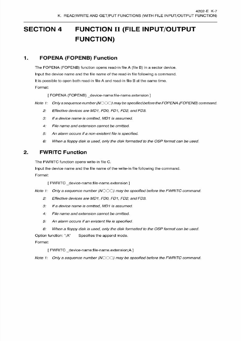
8/15/2019 Okuma Manuals 391
http://slidepdf.com/reader/full/okuma-manuals-391 377/397
4202-E
K-7
K.
READ/WRITE
AN D
GET/PUT
FUNCTIONS
(WITH
FILE
INPUT/OUTPUT
FUNCTION)
SECTION 4 FUNCTION
II (FILE
INPUT/OUTPUT
FUNCTION)
1. FOPENA
(FOPENB)
Function
The
FOPENA (FOPENB) function
opens
read-in file
A
(file
B)
in
a sector
device.
Input
the
device name and
the
file name of
the
read-in
f ile following
a command.
It is
possible
to open
both
read-in file
A
and
read-in
file
B
at
the same
time.
Format:
[
FOPENA (FOPENB)
_device-name:file-name.extension
]
Note
1:
Only
a
sequence
number
(NOOO)
maybe
specified
before
the
FOPENA
(FOPENB)
command,
2:
Effective
devices are
MD1,
FDO, FD1,
FD2,
and
FD3.
3: If a device
name
is
omitted,
MD1
is assumed.
4:
File name and extension cannot be omitted.
5:
An
alarm
occurs
if
a
non-existent
file is
specified.
6:
When
a
floppy
disk is
used,
only
the
disk
formatted to
the
OSP
format can be
used.
2.
FWRITC Function
The FWRITC funct ion
opens
write-in file
C.
Input
the
device name and the file
name
of
the write-in file following
the
command.
Format:
[ FWRITC
_device-name:file-name.extension
]
Note
1: Only
a
sequence
number
(NOOO)
may
be
specified
before
the FWRITC
command.
2:
Effective
devices are MD1,
FDO, FD1,
FD2, and
FD3.
3:
If
a device
name
is omitted,
MD1
is assumed.
4:
File
name
and extension cannotbe omitted.
5:
An
alarm occurs
if
an existent file is
specified.
6:
When
a
floppy
disk is
used,
only the disk formatted to
the
OSP
format can be used.
Option
function:
“;A”
Specifies
the
append
mode.
Format:
[
FWRITC _device-name:file-name.extension;A
]
Note
1: Only
a
sequence
number
(NOOO)
may
be
specified
before
the
FWRITC command.

8/15/2019 Okuma Manuals 391
http://slidepdf.com/reader/full/okuma-manuals-391 378/397
4202-E
K-8
K.
READ/WRITE
AN D
GET/PUT
FUNCTIONS
(WITH
FILE
INPUT/OUTPUT
FUNCTION)
Note
2:
Effective devices are
MD1,
FDO,
FD1, FD2,
and
FD3.
3:
If a device
name is
omitted, MD1
is assumed.
4:
File name and
extension cannot
be omitted.
5:
An
alarm
occurs
if
an
existent
file
is
specified.
6:
When a
floppy
disk is
used,
only the disk
formatted
to
the OSP format can
be
used.
3.
READ
Function
The read
function
sends
the
data
from
read-in
file
A
or B
which has
been
opened
by
the
execution of
the
FOPENA
(B)
command
to
the
read
area
(max.
1
60
characters) in
unit
of lines.
At each
execution
of the
READ
command,
data is sent
by
one
line.
In
the
read
area,
the data is
processed by
the GET command
explained
below.
Format:
[
READ n ]
n:
Designation
of the file where the data is sent to
the read
area.
A . . .
One
line of data is read
from
read-in
file
A
B . . .
One
line
of data is
read
from
read-in
file
B
Note 1:
Only
a
sequence number
(NOOO)
may be
specified
before the
READ
command.
2: If one
line of data which is read from a file exceeds
160
characters,
execution of the
READ
commandends after
sending
160
characters
of
the
data. In
the next execution
of
the
READ
command,
the data
is
sent
from the
remaining
data.
3:
Only
one
read
area exists.
The
existing
data
in
the
read
area
is
destroyedby
theexecution of
the
READ
command.
4.
WRITE
Function
The write function sends
(writes)
the
data in the
write
area (max. 1
60
characters) to the write-in file
C
which
is
opened by
the
execution
of the FWRITC command.
A
carriage return code
($0A)
is
appended
to the end
of
the data.
At each
execution of the
WRITE
command,
on e
line
of
data is written.
In the write area, the data is
written
by the
PUT
command
explained
below.
Format:
[
WRITE
C
]
Note 1: Only
a sequence number
(NOG
O)
may be
specifiedbefore
the
WRITE
command.
2:
Although
the
write/read
area
has the
capacity
to store
the
data
of
up to 160 characters,
it is
recommended
to
limit the
number
of
characters
at 64
characters to give
better
visibility.
3:
One line
means
a
unit of
data delimited
by
a carriage return code ($0A).
4:
The
read
(write)
pointer
is
zero
cleared
at
the
execution
of
the READ
(WRITE)
command.
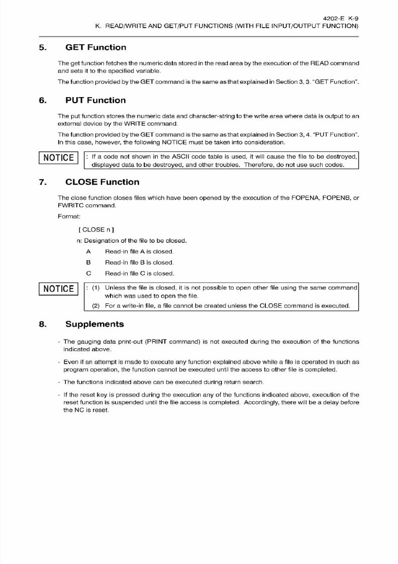
8/15/2019 Okuma Manuals 391
http://slidepdf.com/reader/full/okuma-manuals-391 379/397
4202-E
K-9
K.
READ/WRITE
AN D
GET/PUT
FUNCTIONS
(WITH
FILE
INPUT/OUTPUT
FUNCTION)
5.
GET Function
The
ge t
function fetches the numeric data stored in the read area
by
the
execution
of
the
READ
command
and
sets it to the
specified
variable.
The
function
provided by
the GET
command
is the same as that
explained
in
Section
3, 3.
‘‘GET Function”.
6. PUT
Function
The
put
function
stores the
numeric
data
and
character-string
to
the
write area where data is
output to an
external
device
by
the WRITE command.
The
function
provided
by
the
GET command
is
the
same as that
explained
in
Section 3, 4.
‘‘PUT
Function”.
In
this
case,
however,
the
following
NOTICE
must
be taken into consideration.
NOTICE
:
a
code
not
shown in the ASCII code table
is used, it
will
cause the
file
to
be
destroyed,
displayed
data to be
destroyed,
and
other
troubles.
Therefore,
do not
use
such codes.
7.
CLOSE
Function
The close funct ion closes f iles
which
have been
opened
by
the
execution of
the
FOPENA,
FOPENB,
or
FWRITC
command.
Format:
[ CLOSE n ]
n:
Designation
of
the
file
to be closed.
A
Read-in
file
A
is closed.
B
Read-in
file
B
is
closed.
C Read-in file C
is
closed.
NOTICE
: (1)
Unless
the f ile
is
closed,
it is
not
possible
to open
other f ile
using
the
same
command
which
was
used to
open
the
file.
(2)
Fo r a
write-in
file,
a
file
cannot
be created unless the
CLOSE
command is executed.
8.
Supplements
- The
gauging
data
print-out
(PRINT command)
is not
executed
during
the execution
of
the
functions
indicated above.
-
Even
if
an
attempt
is
made to execute
any
function
explained above while
a
file
is
operated
in
such as
program
operation,
the
function
cannot be executed unti l the
access
to other
file
is
completed.
-
The
functions
indicated
above can
be
executed
during return
search.
-
If
the
reset key
is
pressed
during
the
execution any
of the functions
indicated
above,
execution of the
reset
function
is
suspended
until
the
file
access
is
completed.
Accordingly,
there
will be
a
delay
before
the
NC is reset.
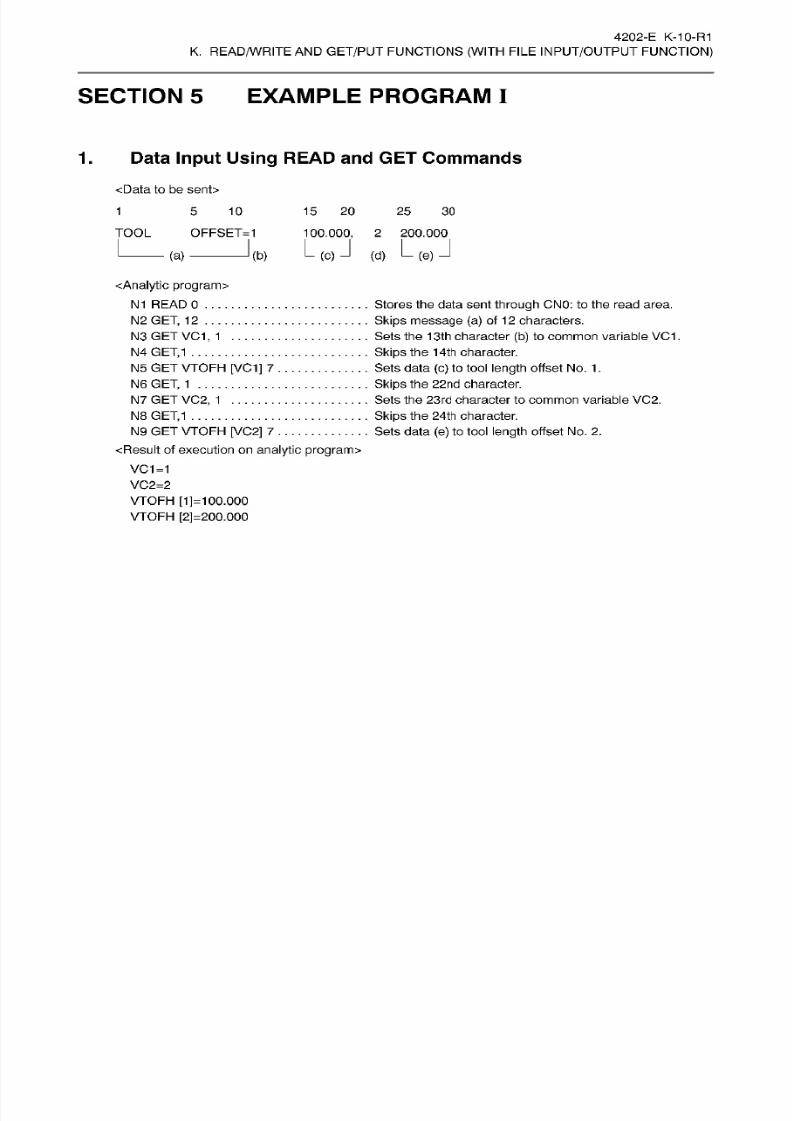
8/15/2019 Okuma Manuals 391
http://slidepdf.com/reader/full/okuma-manuals-391 380/397
4202-E K-10-R1
K.
READ/WRITE
AN D
GET/PUT
FUNCTIONS
(WITH
FILE
INPUT/OUTPUT
FUNCTION)
SECTION 5
EXAMPLE PROGRAM
I
1. Data
Input
Using
READ
and
GET Commands
<Data
to
be
sent>
1
5
10
15
20 25
30
TOOL OFFSET=1
100.000, 2
200.000
(d)
L(e)J
J
a) (b)
<Analytic program>
N1
READ0
N2 GET, 12
N3
GET
VC1,
1
N4
GET,1
N5
GE T V TOFH [VC1] 7
N6 GET,
1
N7
GET
VC2,
1
N8
GET,1
N9
GET
VTOFH
[VC2] 7
<Result of execution
on analytic
program>
VC1=1
VC2=2
VTOFH
[1]=1
00.000
VTOFH
[2]=200.000
Stores the
data sent
through
CN0:
to the
read area.
Skips
message
(a)
of
1
2
characters.
Sets
the
13th
character
(b)
to common variable VC1
.
Skips
the 14th character.
Sets data
(c)
to tool length offset No.
1
.
Skips
the
22nd
character.
Sets the
23rd
character
to
common
variable VC2.
Skips
the 24th character.
Sets
data
(e)
to
tool
length
offset
No.
2.
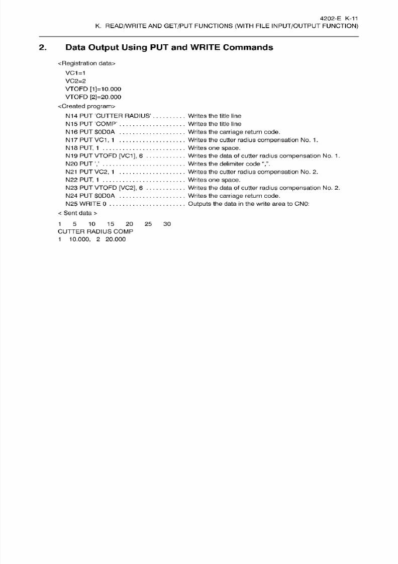
8/15/2019 Okuma Manuals 391
http://slidepdf.com/reader/full/okuma-manuals-391 381/397
4202-E
K-11
K.
READ/WRITE
AN D
GET/PUT
FUNCTIONS
(WITH
FILE
INPUT/OUTPUT
FUNCTION)
2.
Data
Output
Using
PUT
and
WRITE
Commands
<
Registration
data>
VC1=1
VC2=2
VTOFD
[1]=10.000
VTOFD [2]=20.000
<Created program>
N14
P UT C UTT ER RADIUS’
N15
PUT ’COMP’
N16
PUT $0D0A
N17
PUT VC1,
1
N18
PUT,
1
N19 PU T
VTOFD
[VC1],
6 ..
N20 PUT
N21PUTVC2,
1
N22
PUT,
1
N23 PU T VTOFD
[VC2],
6
..
N24
PUT $0D0A
N25
WRITE
0
<
Sent
data
>
Writes the t it le line
Writes the
title
line
Writes
the carriage
return
code.
Writes the cutter radius compensation No . 1
.
Writes one space.
Writes the data of cutter radius
compensation
No.
1.
Writes the delimiter
code
Writes the
cutter
radius
compensation
No.
2.
Writes
one space.
Writes the data of cutter radius
compensation
No.
2.
Writes the carriage
return
code.
Outputs
the
data
in
the write area to
CNO:
1
5
10
15
20
25 30
CUTTER RADIUS COMP
1
10.000,
2
20.000
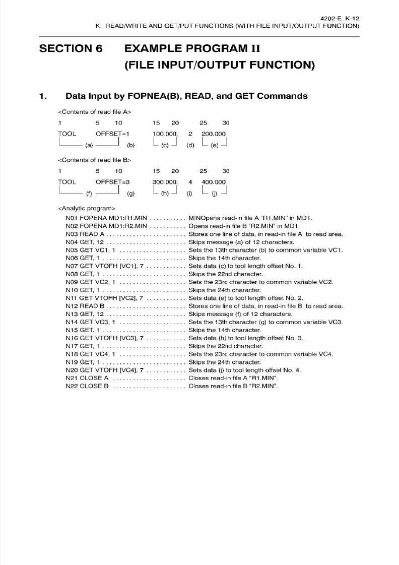
8/15/2019 Okuma Manuals 391
http://slidepdf.com/reader/full/okuma-manuals-391 382/397
4202-
E
K-12
K.
READ/WRITE
AN D
GET/PUT
FUNCTIONS
(WITH
FILE
INPUT/OUTPUT
FUNCTION)
SECTION 6
EXAMPLE PROGRAM
II
(FILE
INPUT/OUTPUT
FUNCTION)
1.
Data
Input
by
FOPNEA(B),
READ,
and GET
Commands
<Contents
of
read file A>
1
5 10 15 20 25 30
TOOL OFFSET=1
100.000, 2
200.000
L
(c)
J
(d)
L
(e)
J
a) (b)
cContents of
read file
B>
1
5
10
15
20 25 30
TOOL
OFFSET=3 300.000,
4
400.000
L
(h)
J
(i)
L
(j)
J
9
(g)
<Analytic
program>
N01
FOPENA
MD1
:R1.MIN
N02
FOPENA
MD1:R2.MIN
N03
READ
A
N04
GET, 12
N05 GET
VC1,
1
N06
GET,
1
N0 7 GET
VTOFH
[VC1],
7
.
N08
GET, 1
N09 GET
VC2,
1
N10
GET, 1
N11 GET
VTOFH [VC2],
7 .
N12 REA D B
N13
GET,
12
N14
GET VC3, 1
N15
GET,
1
N16
GET
VTOFH
[VC3],
7 .
N17
GET,
1
N18GETVC4,
1
N19
GET,
1
N20
GET
VTOFH [VC4],
7 .
N21
CLOSE
A
N22
CLOSE
B
MINOpens
read-in
file
A “R1 .MIN in MD1
.
Opens
read-in
file
B
“R2.MIN” in
MD1 .
Stores
one l ine
of
data, in
read-in
file A,
to read
area.
Skips
message
(a)
of
12
characters.
Sets
the 13th character
(b)
to common variable VC1
.
Skips
the
1
4th
character.
Sets
data
(c)
to tool
length
offset
No .
1 .
Skips
the 22nd character.
Sets the
23rd character to common variable
VC2.
Skips
the
24th
character.
Sets data
(e)
to tool
length
offset
No. 2.
Stores
one line of
data, in
read-in file
B,
to
read
area.
Skips
message
(f)
of
1
2
characters.
Sets
the 1
3th
character
(g)
to common variable
VC3.
Skips
the 14th character.
Sets
data
(h) to tool
length
offset
No. 3.
Skips
the
22nd character.
Sets
the 23rd
character to common variable
VC4.
Skips
the 24th character.
Sets
data (j) to
tool
length offset
No.
4.
Closes
read-in
file
A “R1.MIN”.
Closes
read-in file
B “R2.MIN”.
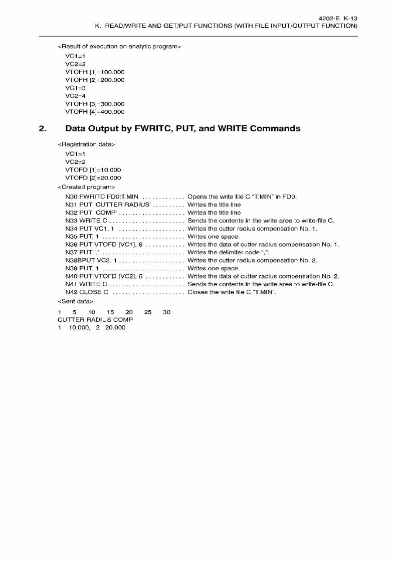
8/15/2019 Okuma Manuals 391
http://slidepdf.com/reader/full/okuma-manuals-391 383/397
4202-E K -13
K.
READ/WRITE
AN D
GET/PUT
FUNCTIONS
(WITH
FILE
INPUT/OUTPUT
FUNCTION)
<Result of execution on
analytic
program>
VC1=1
VC2=2
VTOFH
[1]=1
00.000
VTOFH
[2]=200.000
VC
1=3
VC2=4
VTOFH
[3] =300.000
VTOFH
[4]
=400.000
2.
Data Output by
FWRITC,
PUT,
and
WRITE
Commands
Registration
data>
VC1=1
VC2=2
VTOFD
[1]=10.000
VTOFD
[2]
=20.000
cCreated
program>
N30
FWRITC FD0:T.MIN
...
N31 PUT CUTTER RADIUS’
N32
PUT
COMP’
N33
WRITE
C
N34
PUT
VC 1, 1
N35
PUT,
1
N36
PUT
VTOFD
[VC1],
6
. .
N37
PUT
N38BPUT
VC2,
1
N39
PUT, 1
N40
PUT
VTOFD
[VC2],
6
. .
N41
WRITE
C
N42
CLOSE
C
<Sent data>
Opens
the
write file
C
“T.MIN’’
in
FD0.
Writes the
title
line
Writes the
title
line
Sends
the
contents
in
the
write
area to
write-file
C.
Writes the
cutter
radius
compensation
No.
1
.
Writes
one
space.
Writes the data
of
cutter
radius
compensation
No . 1
.
Writes the delimiter code
Writes the
cutter
radius
compensation
No .
2.
Writes
one
space.
Writes
the
data of cutter radius
compensation No . 2.
Sends the contents
in
the write area to
write-file
C.
Closes the write file
C
“T.MIN”.
1
5 10 15 20 25 30
CUTTER RADIUS COMP
1 10.000, 2
20.000
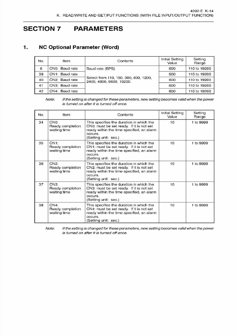
8/15/2019 Okuma Manuals 391
http://slidepdf.com/reader/full/okuma-manuals-391 384/397

8/15/2019 Okuma Manuals 391
http://slidepdf.com/reader/full/okuma-manuals-391 385/397
4202-
E
K-15
K.
READ/WRITE
AN D
GET/PUT
FUNCTIONS
(WITH
FILE
INPUT/OUTPUT
FUNCTION)
2.
NC
Optional
Parameter
(Bit)
Initial
Setting
Value
No. bit
Contents Set
1 SetO
There
is
a
tape
delimiting
code. NULL
3 0
Note: The
“%”
code
is “$25”
(JIS
8
code) or
“$A5”
(JIS
7
code).
Initial
Setting
Value
No. bit
Contents
Set 1
SetO
Stop bit
of
CNO:
2
bit
1
bit
0
Ready signal
of
CNO:
Internal
READY
External
READY
1 1
Parity check of CNO: Checked Not 0
checked
3
Parity
of
CNO:
Even
Odd
0
8
8-bit JIS of CNO:
There
is There is 0
not
5
DC code control of
CNO:
There is There is
0
not
DC
code
control
type
2
of CNO:
Executed Not
0
executed
7
Stop
bit of CN1:
1
bit
2
bit 0
Ready signal
of
CN1:
Internal
READY
External
READY
1
Parity
check of
CN1:
Checked Not 0
checked
3
Parity
of CN1:
Even
Odd
0
13
8-bit JIS of CN1:
There
is
There
is 0
not
5
DC code control of C N1: There is There
is
0
not
DC
code control
type 2
of
CN 1:
Executed Not 0
executed
7
Note
1:
With
this
specification,
iftheJIS
7
code is
selected
fordata
transmission,
it
isprocessed
as
the ISO code.
2: If the
setting
is
changedfor these
parameters,
new
settingbecomes
valid
when thepower
is
turned
on
after
it
is
turned
off
once.
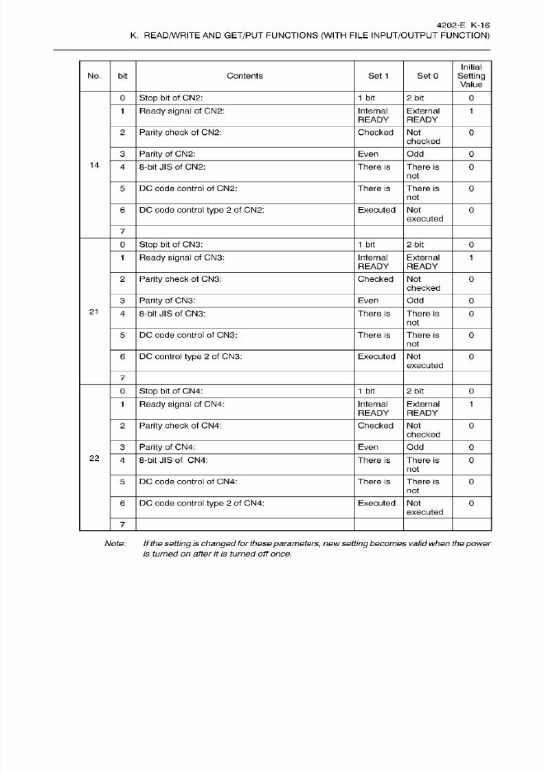
8/15/2019 Okuma Manuals 391
http://slidepdf.com/reader/full/okuma-manuals-391 386/397
4202-E K -16
K.
READ/WRITE
AN D
GET/PUT
FUNCTIONS
(WITH
FILE
INPUT/OUTPUT
FUNCTION)
Initial
Setting
Value
No. bit Contents
Set
1
SetO
Stop bit
of CN2:
1
bit
2
bit 0
Ready signal
of CN2:
Internal
READY
External
READY
1
1
Parity
check
of
CN2:
Checked No t 0
checked
Parity
of
CN2:
Even
Odd
0
14
8-bit JIS of CN2:
There is There
is 0
not
DC
code control
of
CN2: There
is
There
is
0
not
DC code control
type 2
of CN2: Executed Not 0
executed
7
Stop
bit of
CN3:
1
bit
2
bi t
0
Ready signal
of
CN3:
Internal
READY
External
READY
1 1
Parity
check of
CN3: Checked
Not 0
checked
Parity
of CN3: Even Odd 0
21
8-bit
JIS of
CN3:
There
is
There
is 0
not
DC code
control of
CN3:
There
is
There
is
0
not
DC
control type
2
of
CN3:
Executed Not 0
executed
7
Stop
bit of CN4:
1
bit
2
bi t
0
Internal
READY
Ready
signal
of CN4:
External
READY
1
1
Parity
check of
CN4: Checked
Not 0
checked
Parity
of CN4: Even
Odd
0
22
8-bit
JIS of CN4: There
is
There is 0
not
DC
code control of
CN4:
There is There is
0
not
DC code
control
type
2
of CN4: Executed Not
0
executed
7
Note: If
the
setting
is
changed
for these
parameters,
new
setting
becomes
valid
when the
power
is turned
on
after
it
is
turnedoff
once,
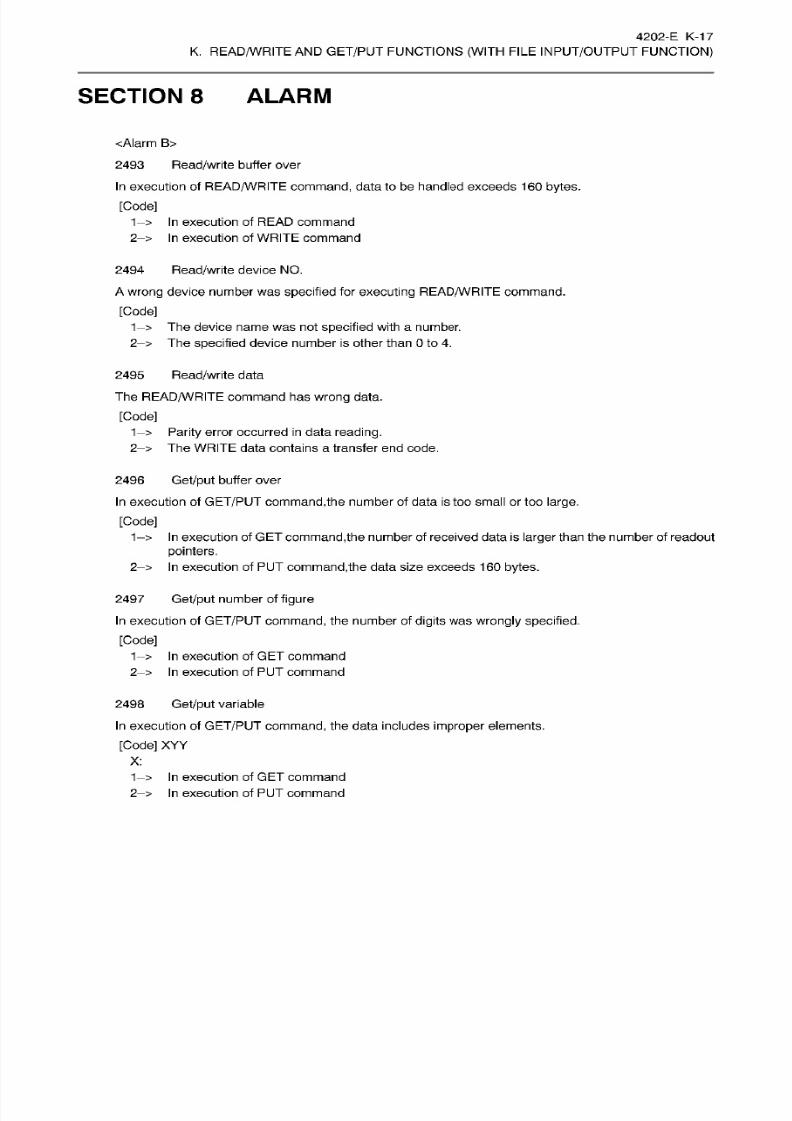
8/15/2019 Okuma Manuals 391
http://slidepdf.com/reader/full/okuma-manuals-391 387/397
4202-
E K-1 7
K.
READ/WRITE
AN D
GET/PUT
FUNCTIONS
(WITH
FILE
INPUT/OUTPUT
FUNCTION)
SECTION 8 ALARM
<Alarm
B>
2493
Read/write
buffer
over
In
execution
of
READ/WRITE
command,
data to be handled exceeds 16 0
bytes.
[Code]
1-> In
execution of
READ command
2
>
In
execution of
WRITE command
Read/write
device NO.494
A
wrong
device number was
specified
for
executing
READ/WRITE
command.
[Code]
The
device
name
was not
specified
with
a
number.
2—
>
The
specified
device
number
is other
than
0 to
4.
2495
Read/write
data
The
READ/WRITE
command has
wrong
data.
[Code]
1->
Parity
error
occurred
in
data reading.
2—
>
The
WRITE
data contains a transfer end code.
2496
Get/put
buffer over
In
execution of
GET/PUT
command,
the number of data is too small o r too
large.
[Code]
1-> In
execution
of GET
command,
the number of received data is
larger
than the number of readout
pointers.
2- >
In
execution of
PUT
command,the
data size exceeds 160
bytes.
2497
Get/put
number of
figure
In
execution of
GET/PUT
command,
the number of
digits
was
wrongly
specified.
[Code]
1->
In
execution of
GE T
command
2—
>
In
execution of PU T command
2498 Get/put
variable
In
execution of
GET/PUT
command,
the data
includes
improper
elements.
[Code] XYY
X:
1->
In
execution of GET command
2- > In
execution of
PUT command
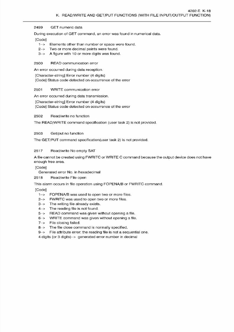
8/15/2019 Okuma Manuals 391
http://slidepdf.com/reader/full/okuma-manuals-391 388/397
4202-
E
K-18
K.
READ/WRITE
AN D
GET/PUT
FUNCTIONS
(WITH
FILE
INPUT/OUTPUT
FUNCTION)
GET numeric data
During execution of GET
command,
an error
was
found
in
numerical data.
[Code]
1->
Elements other
than number
or
space were found.
2—
>
Tw o or more decimal points were found.
3-> A figure
with 10
or
more
digits
was found.
2499
2500
READ
communication error
An
error
occurred during
data
reception.
[Character-string]
Error number
(4
digits)
[Code] Status code detected
on
occurrence of the error
2501
WRITE
communication error
An
error
occurred
during
data
transmission.
[Character-string]
Error
number (4 digits)
[Code]
Status
code
detected
on
occurrence
of the error
2502
Read/write
no function
The
READ/WRITE
command
specification (user
task
2)
is
not
provided.
2503
Get/put
no
function
The
GET/PUT
command
specification(user
task
2)
is not
provided.
251
7
Read/write
No
empty
SAT
A
file cannot be created
using
FWRITC or
WRITE
C command because
the output
device does not have
enough
free area.
[Code]
Generated error No.
in
hexadecimal
251
8
Read/write
File
open
This alarm occurs
in
file
operation
using
FOPENA/B
or FWRITC command.
[Code]
1->
FOPENA/B
was
used
to
open
two
or
more files.
2- >
FWRITC was used to
open
two
or
more
files.
3-> The
writing
file
already
exists.
4—
>
The
reading
file is not
found.
5->
READ
command
was
given
without
opening
a
file.
6->
WRITE
command was
given
without
opening a
file.
7—
>
File
closing failed.
8->
The
file
close command is
normally
specified.
9—
>
File
attribute
error: the
reading file
is not a
sequential
one.
4 digits
(or
3
digits)—
>
generated
error
number in
decimal
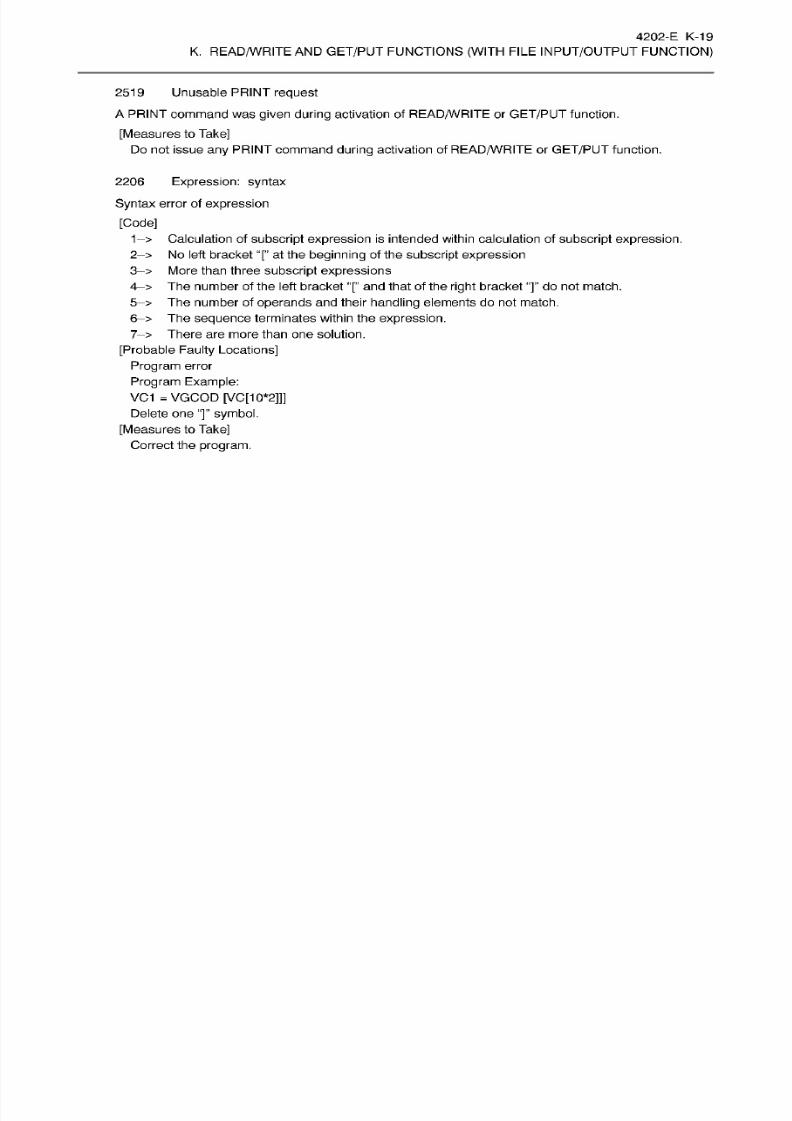
8/15/2019 Okuma Manuals 391
http://slidepdf.com/reader/full/okuma-manuals-391 389/397
4202-
E
K-19
K.
READ/WRITE
AN D
GET/PUT
FUNCTIONS
(WITH
FILE
INPUT/OUTPUT
FUNCTION)
Unusable
request
A
PRINT command was given
during
activation of
READ/WRITE
or
GET/PUT
function.
[Measures to Take]
Do not issue
any
command
during
activation of
READ/WRITE
or
GET/PUT
function.
2519
Expression:
syntax
Syntax
error of
expression
[Code]
1
>
Calculation of
subscript expression
is
intended within
calculation
of
subscript expression.
2—
>
No left bracket
“[” at the beginning
of
the
subscript
expression
3
>
More than three subscript expressions
4-> The number
of
the left bracket
“[”
and
that of
the
right
bracket “]” do
not
match.
5—
>
The
number of operands
and
their
handling
elements do
not
match.
6-> The sequence terminates within the
expression.
7—
>
There are more than one solution.
[Probable
Faulty Locations]
Program
error
Program
Example:
VC 1
=
VGCOD [VC[10*2]]]
Delete on e
“]” symbol.
[Measures
to
Take]
Correct the
program.
2206
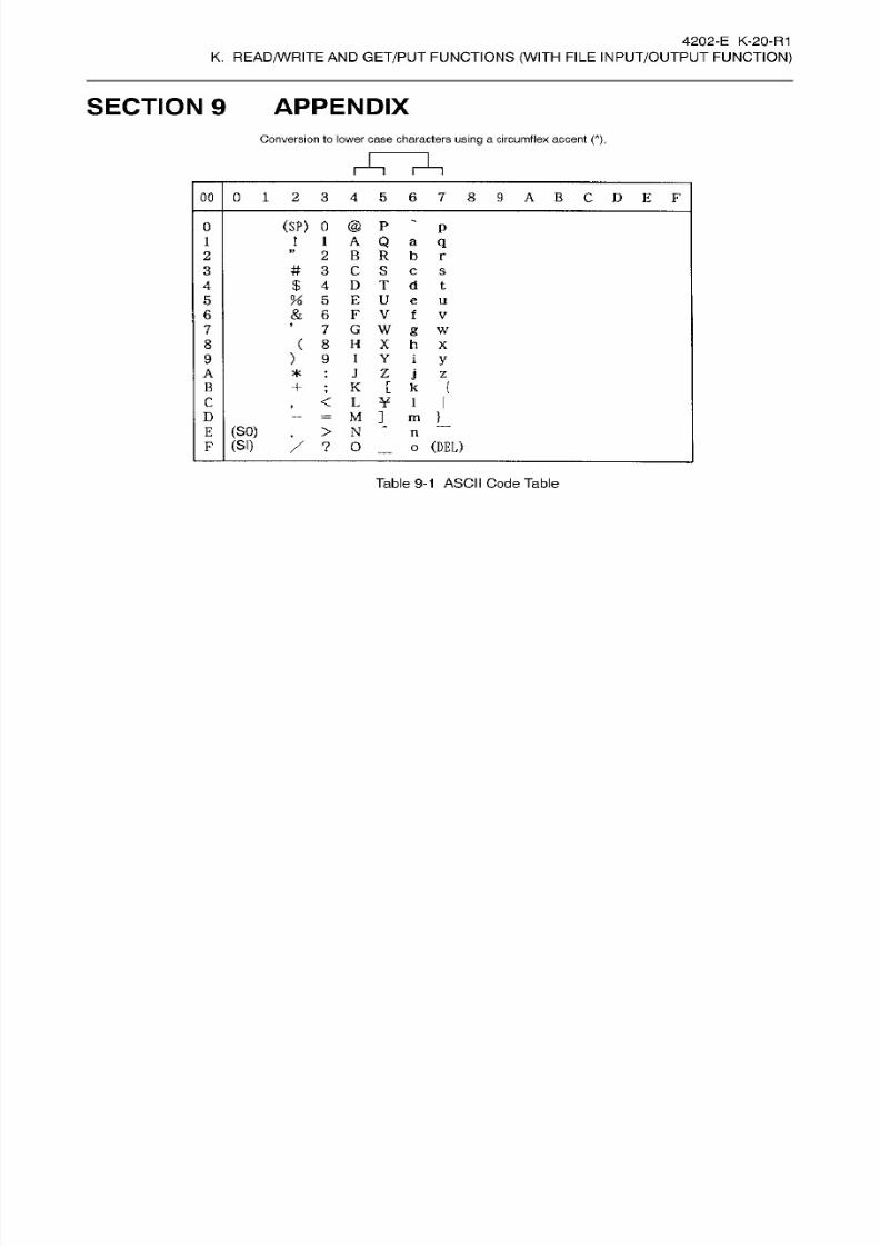
8/15/2019 Okuma Manuals 391
http://slidepdf.com/reader/full/okuma-manuals-391 390/397
4202-E K-20-R1
K.
READ/WRITE
AN D
GET/PUT
FUNCTIONS
(WITH
FILE
INPUT/OUTPUT
FUNCTION)
SECTION 9
APPENDIX
Conversion to lower case characters
using
a circumflex accent
( ),
00
0
1
23456789ABCDEF
(SP)
0
@
P
~
p
1
A
Q
a
q
”
2
B
R
b
r
#
3
C S
c
s
$
4
D
T
d t
%
5
E
U
e
u
&
6
F V f
v
’
7
G
W
g
w
(
8
H
X h x
)
9
I Y i
y
J
Z
j
z
K
[
k
(
,
<
L
¥
1
I
-
=
M
]
m
}
.
>
N
*
/
? 0
_
o
(DEL)
0
1
2
3
4
5
6
7
8
9
A
*
:
B
C
D
(SO)
n
(SI)
Table 9-1
ASCII Code
Table

8/15/2019 Okuma Manuals 391
http://slidepdf.com/reader/full/okuma-manuals-391 391/397
L.
Hi-CUT

8/15/2019 Okuma Manuals 391
http://slidepdf.com/reader/full/okuma-manuals-391 392/397
4202-E
L-1
L. Hi-CUT
SECTION
1
OVERVIEW OF
Hi-CUT
In
the
“Hi-Cut”
control
mode,
feedrates
are controlled
during
cutting
corners
and
arcs
meeting
the
shape
of
them to shorten
cutting
time while
maintaining
high
shape
accuracy.
8/15/2019 Okuma Manuals 391
http://slidepdf.com/reader/full/okuma-manuals-391 393/397
4202-E
L-2
L. Hi-CUT
SECTION 2 Hi-CUT CONTROL FUNCTION
(1)
By designating
the
upper
limit
of
the
cutting
feedrate, which is
determined
according
to
cutting
conditions (workpiece
material,
tool
type, spindle speed,
etc.),
the
maximum
value of
feedrate
is
clamped
at
this
upper
limit.
Therefore,
automatic
feedrate control
which
meets
the
cutting
conditions
is
enabled.
(2) Furthermore,
the
Hi-Cut
control
function
“automatically
determines
the optimum
servo
control
parameters
best fitting to cutting’’
based on
the upper
limit
of feedrate
which
is determined
according
to the
cutting
conditions.
Therefore, high-speed, high-accuracy machining
is
always
possible
regardless
of
cutting
conditions.
(3)
Because
automatic
cutting
feedrate control
in
the Hi-Cut control function
is
carried out while
actual tool
position
is
monitored, machining accuracy is
consistently
high.
1.
Designating
Hi-Cut Control Mode
To turn
on
the Hi-Cut control
function, designate
the
“Hi-CUT
CONTROL ON .
(1)
Se t
the
following parameters
according
to
the
type
of
machining:
(a)
MAXIMUM
FEEDRATE
(b)
WORK TOLERANCE
(2) Designation
of the Hi-Cut
control
mode
is
made
in
the
following
two
methods:
(a) Parameter
setting
(b)
Program
command
(3) The
Hi-Cut
control is effective
only
to
the cutting
feed commands
in
the
“ feed per minutes”
mode
programmed in
the Hi-Cut
control
mode. In
other
words,
the
Hi-Cut control
is
not
effective
to the
rapid
feed commands and
the
feed/rev.
commands
programmed in
the Hi-Cut
control mode.
(4)
Th e
Hi-Cut
control mode
assumes
the machines
having
three basic control
axes,
X,
Y,
and
Z.
Therefore,
it is
not valid for
an
additional
axis
such
as
U, V, W,
A, B,
an d C.
2.
Hi-Cut
Control Parameters
(1)
MAXIMUM
FEEDRATE
(a)
Feedrate
upper limit
sets
the maximum
value
of feedrate
which is
applicable
when
cutting
is
carried out
using
the Hi-Cut control.
Feedrate
upper limit
=
Maximum value
of feedrate command
(b)
Because the
Hi-Cut
control
function
determines automatically the
optimum
servo
control
parameters
using the
feedrate upper limit
value,
consistently
high
accuracy
with
high speed is
guaranteed
for
any
type
of
machining.
Therefore,
if
the maximum feedrate
changes
due to the
change in
the
type
of
machining, it is
recommended to
change
the
setting
for
this
parameter.
(c)
The maximum value
of
feedrate
designated
in
“per
minute” mode is limited
by
this value.
8/15/2019 Okuma Manuals 391
http://slidepdf.com/reader/full/okuma-manuals-391 394/397
4202-E
L-3
L. Hi-CUT
(2) WORK TOLERANCE
(a) This
parameter
sets the allowable
machining
error when
the
workpiece is machined
using
the
Hi
-Cut control
function.
Tolerance
=
Allowable
machining
error
By sett ing
this
parameter,
the
workpiece
is
finished
within
allowable
error.
(b) Because
the
Hi-Cut
control function controls
cutting
feedrate based on
the
set
tolerance,
it
is
recommended to
se t a
large
value
within allowable error
so that a workpiece
is machined
by
high feedrates.
Du e
to
the
control
characteristic
that diameter reduction
in
arc cutt ing and dulling
at corners
will
become greater
as
higher
feedrate is
used, although
smaller tolerance
reduces
error,
feedrate
is
lowered at the
same elongating
total
cutting
time.
When
cutting
free-formed
curve, which
is approximated with minute motion blocks of line and arc
command
(programmed
shape):
(1)
(c)
In
this
case,
actual
cutting error
is determined
by
the
following
factors:
Error between the
original
surface and the surface
approximated
using
line
segments
-
Machining
toleranc
____
rror between
programmed
shape
and tool
paths
Tool
shape
error
If the
relationship
between the
program
tolerance and
machining
tolerance is
Program
tolerance
<
Machining
tolerance
actual
cutting
error is
as
indicated below.
Allowable
machining
error
>
Actual
machining
error
=
Machining
tolerance
+
Tool
shape error
If
the tool shape
error
is small and
can
be
neglected, designation
of
the
machining
tolerance
as
in
expression
(1),
actual
machining
error is within allowable
machining
error.
However,
if
precise
setting is necessary, the
tolerance must be set as indicated
below.
Tolerance
(machining tolerance)
=
Allowable
machining
error
-
Tool
shape
error
If
the
relationship
as indicated
in
expression
(2)
is not
satisfied, i.e., if the program
tolerance is
greater
than
the
machining tolerance,
actual
machining
error
is
generally
expressed
with
the
following formula.
Allowable
machining
error
>
Actual
machining
error
=
Program
tolerance
+
Tool
shape
error
From
this,
it will
be understood
that
if
the
program
tolerance is
greater
than the allowable
machining
error,
actual
machining
error is
always
greater than
the allowable
machining
error
even
if
the
machining
error
is
set
to a small value.
Therefore,
to machine a
workpiece
within the allowable
machining
error,
it
is
necessary
to set a
smaller value to the
program
tolerance than the allowable
machining
error. To obtain smooth
surface,
setting
of further smaller program tolerance is necessary. From this
point
of
view,
the
program tolerance
should be set to meet
the
following.
Program
tolerance
<
1/2
x
(Allowable machining error)
-
Program
tolerance
(2)
That
is,
Program
tolerance
<
1/2
x
(Machining tolerance)
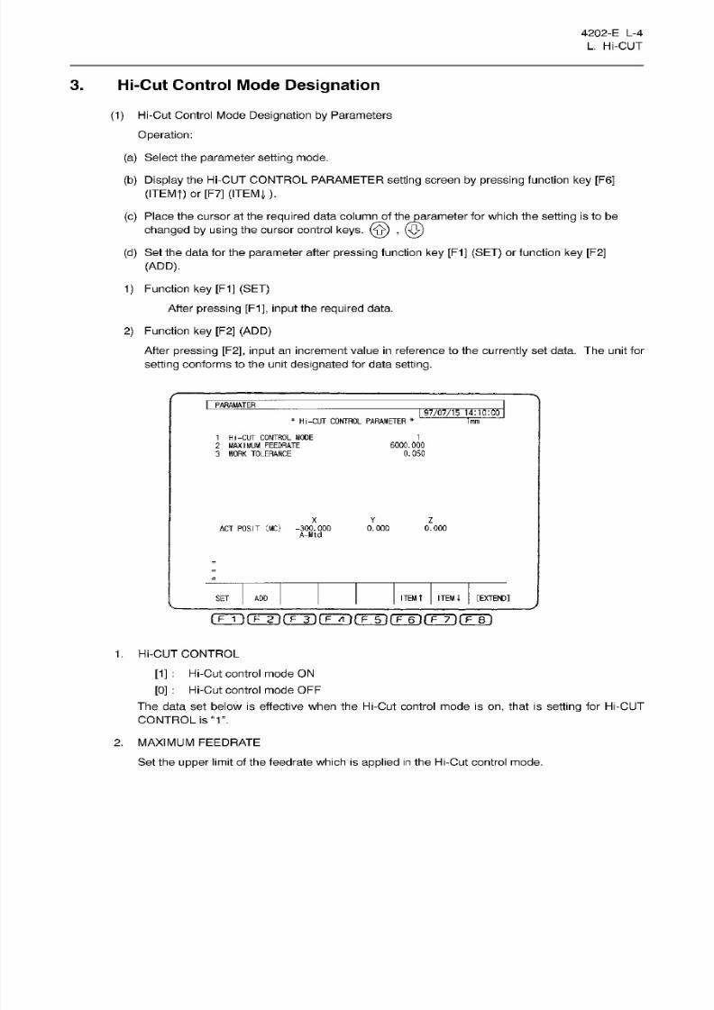
8/15/2019 Okuma Manuals 391
http://slidepdf.com/reader/full/okuma-manuals-391 395/397
4202-E
L-4
L. Hi-CUT
3. Hi-Cut
Control
Mode Designation
(1)
Hi-Cut Control Mode
Designation
by Parameters
Operation:
(a)
Select
the
parameter setting
mode.
(b)
Display
the Hi-CUT CONTROL PARAMETER
setting
screen
by pressing
function
ke y
[F6]
(ITEMf)
or
[F7]
(ITEM
J,
).
(c)
Place the
cursor
at the
required
data column
of
theparameter
for which the
setting
is to
be
changed by using
the cursor control keys.
(§)
,
({£)
(d)
Set
the data for the
parameter
after pressing function key
[F1]
(SET) or
function
key
[F2]
(ADD).
1) Function
key
[F1]
(SET)
After
pressing
[F1],
input the required data.
2)
Function
key
[F2]
(ADD)
After
pressing
[F2],
input
an increment
value
in
reference to the
currently
set
data.
The
unit
for
setting conforms to the
unit
designated
for data setting.
I
PARAMATER
97/07/15
14:10:00
*
Hi-CUT
CONTROL PARAMETER
*
1mm
1
Hi-CUT CONTROL MODE
2 MAXIMUM
FEEDRATE
3
WORK TOLERANCE
6000.000
0.050
X Y
Z
ACT POSIT
CMC)
i°s«r
0.000 0.000
ITEM
t
ITEM
l
[EXTEND]
ET
ADD
rrrÿfFÿrrTi(TTÿ(Tÿrÿ~6irF~7if?~B~)
1.
Hi-CUT CONTROL
[1]
:
Hi-Cut
control
mode
ON
[0]
:
Hi-Cut control
mode OFF
The data
set
below is
effective
when the
Hi-Cut
control mode is
on,
that is
setting
for
Hi-CUT
CONTROL
is
“1”.
2.
MAXIMUM FEEDRATE
Set the
upper
limit of the feedrate which is applied
in
the Hi-Cut control mode.

8/15/2019 Okuma Manuals 391
http://slidepdf.com/reader/full/okuma-manuals-391 396/397
4202-E L-5
L. Hi-CUT
3.
WORK TOLERANCE
Set
the
tolerance which is applied
in
the Hi-Cut control mode.
Setting
of a value smaller than 0.003
mm
is
not allowed.
(2)
Hi-Cut Control
Mode
Designat ion by Program
To
conduct the Hi-Cut control for
only
a
required
part
in
the
program
or
to
change
the
Hi-Cut control
parameter
setting
according to
the part
to be machined, the Hi-Cut control mode
designation
in
a
program
is convenient.
(a)
To carry
out or
cancel the
Hi-Cut
control mode, designate the
following
G codes.
G187F
E
Hi-Cut control mode
ON
Hi-Cut
control mode
OFF
(Cancellation of G187)
186
Follow the
program
unit
system
for the
unit
of
command
(b) Designate
the G187 and G186
blocks
at
the
beginning
and at the end of
blocks
for which
the
Hi-Cut
control
mode is
required.
These
G
codes
must
be designated
in
individual
blocks and
other commands
must
not be
written
in
the same
block.
(c)
When the Hi-Cut
control
mode
called by
the programmed G
code
is
ON, the
Hi-Cut
control
mode designated
by
the
setting
of
the
parameter
becomes
al l ineffective.
(d)
When the Hi-Cut control mode
called by
the
programmed
G
code
is
OFF,
i.e.,
after the
designation
of
G186
or
resetting the
control,
the
Hi-Cut
control
mode
ON/OFF
status
is
determined
by
the
setting
of
the
parameter.
(e)
Designate the
following
address characters and data words
following
the
G187
code.
Although
they
can
de
designated
in
any
order,
both
E
and
F
commands must
always
be
designated.
1)
F
(maximum
feedrate)
Designate
the upper limit feedrate applied
in
the Hi-Cut control mode.
An F
command
in
the G1
87
block does not
specify
a linear
cutting
feedrate.
Designate
the
actual
feedrate in
a block other than the
G187
block.
If
no
F
command is
designated
in
the
G187
block,
an
alarm
occurs
and the
following message
is
displayed
on
the
screen.
Alarm message:
2243
Dataword:
F’
2) E (work tolerance)
Designate
the
machining
tolerance
amount
used in
the
Hi-Cut
control mode.
If
no
E
command
is
designated in
the
G187
block,
an
alarm occurs
and
the
following
message
is
displayed
on
the
screen.
Alarm
message:
2388
Data
word:
‘E’
Designation
of
a
value smaller than 0.003 mm for this parameter is
ignored
and
is
replaced with
0.003
mm
automatically.
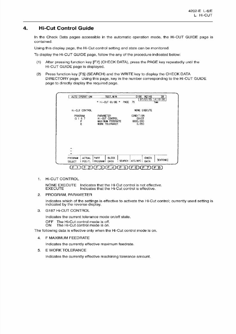
8/15/2019 Okuma Manuals 391
http://slidepdf.com/reader/full/okuma-manuals-391 397/397
4202-E
L-6/E
L. Hi-CUT
4.
Hi-Cut
Control Guide
In
the Check
Data pages accessible
in
the automatic
operation
mode,
the
Hi-CUT GUIDE
page
is
contained.
Using
this
display
page,
the Hi-Cut control
setting
and state
can
be monitored.
To
display
the Hi-CUT GUIDE
page,
follow the
any
of the
procedure
indicated below:
(1)
After
pressing
function
key
[F7]
(CHECK
DATA),
press
the
PAGE
ke y
repeatedly
until
the
Hi-CUT GUIDE
page
is
displayed.
(2)
Press function
key
[F5] (SEARCH)
and
the
WRITE
key
to
display
the CHECK
DATA
DIRECTORY page. Using this page, key in the
number
corresponding
to
the
Hi-CUT GUIDE
page to
directly
display
the
required
page.
0100
N2148
ii
AUTO
OPERATION
TEST.
MIN
I
97/07/15
14:10:00
*
Hi-CUT
GUIDE
*
PAGE
78
1mm
Hi-CUT
CONTROL
NONE EXECUTE
PROGRAM
G
1
8
7
PARAMETER
Hi-CUT CONTROL
MAXIMUM
FEEDRATE
WORK
TOLERANCE
CONDITION
EXIST
6000.000
0.050
F
E
ACTUAL PART
BLOCK
POSIT.
PROGRAM
DATA
CHECK
SEARCH
ATC/APC
DATA
PROGRAM
SELECT
[EXTEND]
(Tji(Tÿ(Tÿ(TÿrFT)frÿfFÿrrr)
1.
Hi-CUT CONTROL
NONE EXECUTE Indicates that the Hi-Cut control
is
not effective.
EXECUTE
2.
PROGRAM, PARAMETER
Indicates
which of the
settings
is effective to activate
the Hi-Cut
control;
currently
used
setting
is
indicated by
the
reverse
display.
3.
G187
Hi-CUT
CONTROL
Indicates the current tolerance mode
on/off
state.
OFF The
Hi-Cut control
mode
is off.
Indicates that the Hi-Cut cont rol is effective.


