OEM Print Engines Operator’s Manual - SATO New Zealand
108
OEM Print Engines Operator’s Manual Read this Operator's Manual before and during the installation of the above printers. Keep this Manual handy for future reference. For printer models: M-8485Se/M-8490Se Standard & Opposite Thermal Transfer M-8459Se Standard Direct Thermal M-8460Se/M-8465Se Wide Web Standard & Opposite Thermal Transfer M-8485Se /M-8490Se /M-8459Se /M-8460Se /M-8465Se
Transcript of OEM Print Engines Operator’s Manual - SATO New Zealand

OEM Print Engines Operator’s Manual
Read this Operator's Manual before and during the installation of the above printers. Keep this Manual handy for future reference.
For printer models:
M-8485Se/M-8490Se Standard & Opposite Thermal Transfer
M-8459Se Standard Direct Thermal
M-8460Se/M-8465Se Wide Web Standard & Opposite Thermal Transfer
M-8485Se /M-8490Se /M-8459Se /M-8460Se /M-8465Se


PREFACE
“Se” PRINT ENGINE OPERATOR’S MANUAL
The Operator’s Manual for the “Se” Print Engine Family contains basic information about the printer such as setup, installation, cleaning and maintenance. It also contains complete instructions on how to use the operator panel to configure the printer. The following is a brief description of each section in this manual.
SECTION 1. PRINTER OVERVIEW
• This section contains a discussion of the printer specifications and optional features.
SECTION 2. INSTALLATION
• This section contains instructions on how to set up the printer and load the labels and ribbon.
SECTION 3. CONFIGURATION
• This section contains information on using the operator panel and switch panels to configure the printer.
SECTION 4. CLEANING AND MAINTENANCE
• This section contains instructions on how to clean and maintain the printer.
SECTION 5. PROGRAMMING
• This section introduces the SATO Programming Language. Full details for programmers can be found in the E Series Programming Reference available separately.
SECTION 6. INTERFACE SPECIFICATIONS• This section contains the printer’s interface specifications, which include
detailed information on how to properly interface your printer to the host system.
SECTION 7. TROUBLESHOOTING• This section contains troubleshooting procedures to follow in the event you
have printer problems.
APPENDICES
• APPENDIX A Optional Accessories

TABLE OF CONTENTS
SECTION 1. PRINTER OVERVIEW
Introduction . . . . . . . . . . . . . . . . . . . . . . . . . . . . . . 1-1General Printer Specifications . . . . . . . . . . . . . . . . . . . . . 1-2
SECTION 2. INSTALLATION
Introduction . . . . . . . . . . . . . . . . . . . . . . . . . . . . . . 2-1Dimensions . . . . . . . . . . . . . . . . . . . . . . . . . . . . . . . 2-2 Component Names . . . . . . . . . . . . . . . . . . . . . . . . . . . 2-3 Rear Panel . . . . . . . . . . . . . . . . . . . . . . . . . . . . . . . 2-4 Switches and Sensors. . . . . . . . . . . . . . . . . . . . . . . . . . 2-5 Media Loading . . . . . . . . . . . . . . . . . . . . . . . . . . . . . 2-6 Adjusting the Label Sensor . . . . . . . . . . . . . . . . . . . . . . . 2-9 Operator Panel . . . . . . . . . . . . . . . . . . . . . . . . . . . . . 2-11DIP Switch Panel . . . . . . . . . . . . . . . . . . . . . . . . . . . . 2-12
SECTION 3. CONFIGURATION
Printer DIP Switch Configuration. . . . . . . . . . . . . . . . . . . . 3-1Default Settings . . . . . . . . . . . . . . . . . . . . . . . . . . . . 3-6 Potentiometer Adjustments. . . . . . . . . . . . . . . . . . . . . . . 3-7 LCD Panel Printer Configuration . . . . . . . . . . . . . . . . . . . . 3-9
Normal Mode . . . . . . . . . . . . . . . . . . . . . . . . . . . . 3-10Advanced Mode . . . . . . . . . . . . . . . . . . . . . . . . . . 3-13
Card Mode . . . . . . . . . . . . . . . . . . . . . . . . . . . 3-17Service Mode . . . . . . . . . . . . . . . . . . . . . . . . . . 3-21Counter Mode . . . . . . . . . . . . . . . . . . . . . . . . . 3-26RFID Mode . . . . . . . . . . . . . . . . . . . . . . . . . . . 3-26
Test Print Mode . . . . . . . . . . . . . . . . . . . . . . . . . . 3-27Default Setting mode . . . . . . . . . . . . . . . . . . . . . . . . 3-28Clear Non-Standard Protocol Codes . . . . . . . . . . . . . . . . 3-28Download User Defined Protocol Codes . . . . . . . . . . . . . . 3-29Hex Dump Mode . . . . . . . . . . . . . . . . . . . . . . . . . . 3-30Hidden Mode/Shift Code Operation . . . . . . . . . . . . . . . . . 3-31
SECTION 4. CLEANING AND MAINTENANCE
Introduction . . . . . . . . . . . . . . . . . . . . . . . . . . . . . . 4-1 Adjusting the Print Quality . . . . . . . . . . . . . . . . . . . . . . . 4-1
Darkness . . . . . . . . . . . . . . . . . . . . . . . . . . . . . . 4-1 Print Speed . . . . . . . . . . . . . . . . . . . . . . . . . . . . . 4-2
Cleaning the Print Head, Platen and Rollers . . . . . . . . . . . . . . 4-2 Cleaning the Sensors and Paper End Switch . . . . . . . . . . . . . . 4-4 Replacing the Print Head . . . . . . . . . . . . . . . . . . . . . . . . 4-5 Replacing the Fuse . . . . . . . . . . . . . . . . . . . . . . . . . . . 4-6
SECTION 5. PROGRAMMING
Introduction . . . . . . . . . . . . . . . . . . . . . . . . . . . . . . 5-1 The SATO RISC Programming Language . . . . . . . . . . . . . . . . 5-1 Selecting Protocol Control Codes . . . . . . . . . . . . . . . . . . . . 5-2 Using Basic . . . . . . . . . . . . . . . . . . . . . . . . . . . . . . . 5-2 The Print Area . . . . . . . . . . . . . . . . . . . . . . . . . . . . . 5-4 Rotated Fields . . . . . . . . . . . . . . . . . . . . . . . . . . . . . 5-7 Command Default Settings . . . . . . . . . . . . . . . . . . . . . . . 5-8 Opposite Hand Models . . . . . . . . . . . . . . . . . . . . . . . . . 5-9 Command Code Page Reference . . . . . . . . . . . . . . . . . . . . 5-10
SECTION 6. INTERFACE SPECIFICATIONS
Introduction . . . . . . . . . . . . . . . . . . . . . . . . . . . . . . 6-1 Interface Types . . . . . . . . . . . . . . . . . . . . . . . . . . . . . 6-1 The Receive Buffer . . . . . . . . . . . . . . . . . . . . . . . . . . . 6-2 IEEE1284 Parallel Interface . . . . . . . . . . . . . . . . . . . . . . 6-3
Electrical Specifications . . . . . . . . . . . . . . . . . . . . . . 6-3 Data Streams . . . . . . . . . . . . . . . . . . . . . . . . . . . . 6-4 Interface Pin Assignments . . . . . . . . . . . . . . . . . . . . . 6-4
RS232C Serial Interface . . . . . . . . . . . . . . . . . . . . . . . . 6-5 General Specifications . . . . . . . . . . . . . . . . . . . . . . . 6-5 Electrical Specifications . . . . . . . . . . . . . . . . . . . . . . 6-5 Pin Assignments . . . . . . . . . . . . . . . . . . . . . . . . . . 6-6 Ready/Busy Flow Control . . . . . . . . . . . . . . . . . . . . . 6-6 X-On/X-Off Flow Control . . . . . . . . . . . . . . . . . . . . . . 6-7
Universal Serial Bus (USB) Interface . . . . . . . . . . . . . . . . . . 6-7 Local Area Network (LAN) Interface . . . . . . . . . . . . . . . . . . 6-8 Bi-Directional Communications . . . . . . . . . . . . . . . . . . . . 6-8
ENQ/ACK/NAK . . . . . . . . . . . . . . . . . . . . . . . . . . . 6-8 Enquire . . . . . . . . . . . . . . . . . . . . . . . . . . . . . . . 6-8 Status Response . . . . . . . . . . . . . . . . . . . . . . . . . . 6-11
Accessory (EXT) Connector. . . . . . . . . . . . . . . . . . . . . . . 6-18 Pin Assignments . . . . . . . . . . . . . . . . . . . . . . . . . . 6-18Standard Operation . . . . . . . . . . . . . . . . . . . . . . . . 6-19Repeat Print . . . . . . . . . . . . . . . . . . . . . . . . . . . . 6-20Error Signals . . . . . . . . . . . . . . . . . . . . . . . . . . . . 6-20
SECTION 7. TROUBLESHOOTING
Initial Checklist . . . . . . . . . . . . . . . . . . . . . . . . . . . . . 7-1 Using the IEEE1284 Parallel Interface . . . . . . . . . . . . . . . . . 7-1 Using the RS232C Serial Interface . . . . . . . . . . . . . . . . . . . 7-3 Using the Universal Serial Bus Interface . . . . . . . . . . . . . . . . 7-4 Using the Local Area Network Interface . . . . . . . . . . . . . . . . 7-4 Error Signals . . . . . . . . . . . . . . . . . . . . . . . . . . . . . . 7-7

APPENDICES
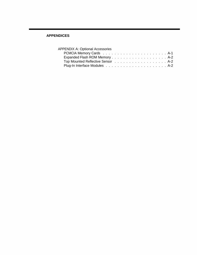
APPENDIX A: Optional AccessoriesPCMCIA Memory Cards . . . . . . . . . . . . . . . . . . . . . . A-1 Expanded Flash ROM Memory . . . . . . . . . . . . . . . . . . . A-2 Top Mounted Reflective Sensor . . . . . . . . . . . . . . . . . . A-2 Plug-In Interface Modules . . . . . . . . . . . . . . . . . . . . . A-2
This page left intentionally blank.

General Printer Specifications (All Models)
SPECIFICATION M-8485Se M-8460Se/ M-8465Se
M-8490Se M-8459Se
PRINT Method Direct or Thermal Transfer Direct Only
Speed (User Selectable) 4 to 12 ips
100 to 300 mm/s4, 6, 8 ips
100 to 200 mm/s4 to 8 ips
100 to 200 mm/s 2 to 5 ips
50 to 125 mm/s
Print Module (Dot Size) .0049 in./.125 mm (8485/8460Se) .0033 in./.083 mm (8465Se)
.0033 in
.083 mm .0049 in. .125 mm
Resolution 203 dpi/ 8 dpmm (8485/8460Se)
305 dpi/ 12 dpmm (8465Se) 305 dpi
12 dpmm 203 dpi 8 dpmm
Maximum Print Width 5.0 in.
128 mm 1024 dots
6.0 in. 152 mm
1216 dots
4.4 in. 112 mm
1344 dots
4.4 in. 112 mm 896 dots
Maximum Print Length 49.2 in, (except 8465Se: 32.8 in.)
1249 mm / (8465Se: 833 mm) 32.8 in. 833 mm
49.2 in. 1249 mm
MEDIA
Minimum Width
1.0 in. (25 mm)
2.0 in. (53mm)
1.0 in. (25 mm)
1.0 in. (25 mm)
Minimum Length
.25 in. (6 mm)
0.6 in. (15 mm)
.25 in. (6 mm)
.25 in. (6 mm)
Maximum Width 5.25 in. 134 mm
6.25 in. 165 mm
5.25 in. 134 mm
5.25 in. 134 mm
Type
Die Cut Labels, Fan-Folded or Continuous
Maximum Caliper 0.10 in. – 0.18mm (Dispensable) 0.10 mm – 0.25 mm (Continuous mode)
Max Unwind Torque
8.8 lbs (4 Kg) with 5 in. wide labels
Backing Paper Rewind Tension
400g or less LABEL SENSING
Gap
Adjustable
Reflective I-Mark
Fixed RIBBON
Maximum Width 5.25 in.
134 mm 6.25 in. 165 mm
5.25 in. 134 mm N/A
Minimum Width
1.55 in. 39.5 mm
1.55 in. 39.5 mm
1.55 in. 39.5 mm N/A
Length
1968 ft (600 M)
N/A All specifications subject to change without notice. 1 Minimum label length at print speeds greater than 6 ips is 1.0 in.
Page i

Section 1. Specifications
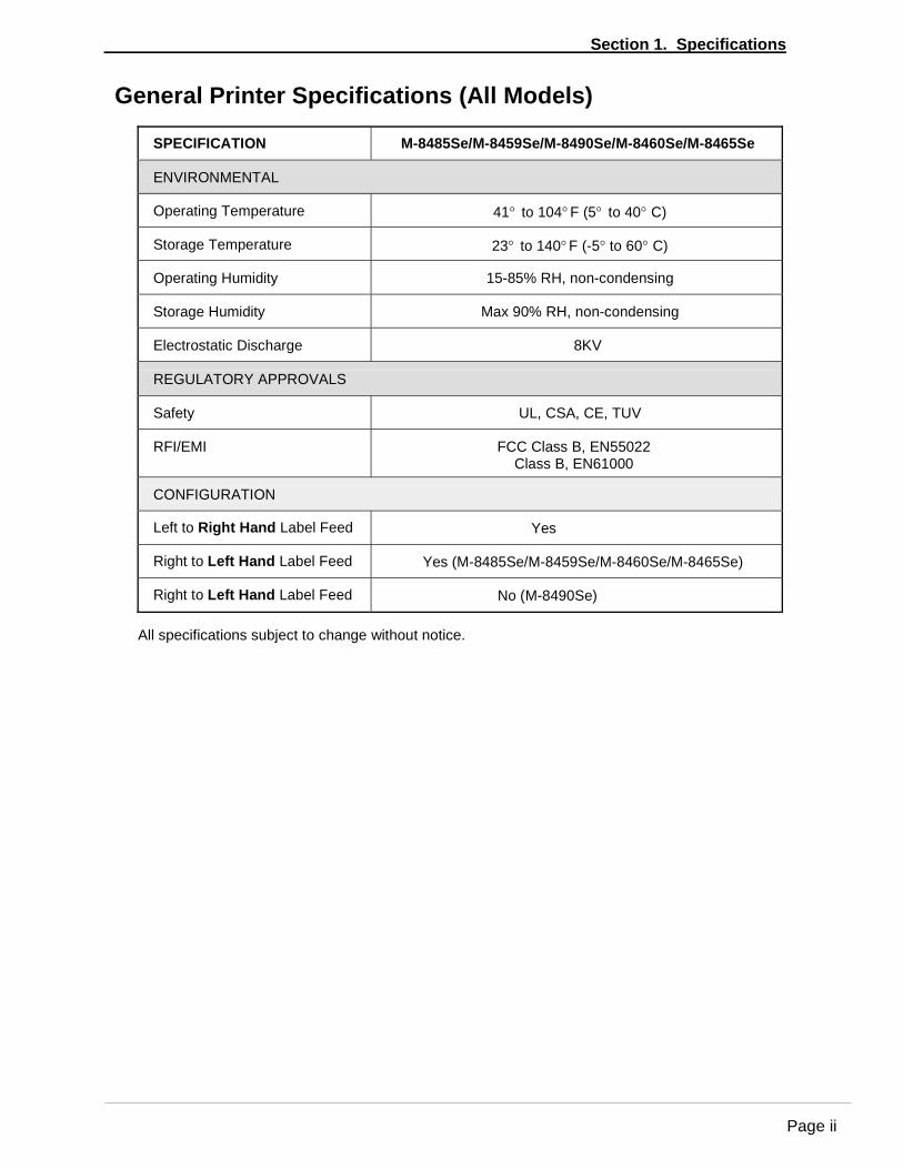
General Printer Specifications (All Models)
SPECIFICATION M-8485Se/M-8459Se/M-8490Se/M-8460Se/M-8465Se
ENVIRONMENTAL
Operating Temperature
41° to 104° F (5° to 40° C)
Storage Temperature
23° to 140° F (-5° to 60° C)
Operating Humidity
15-85% RH, non-condensing
Storage Humidity
Max 90% RH, non-condensing
Electrostatic Discharge
8KV
REGULATORY APPROVALS
Safety
UL, CSA, CE, TUV
RFI/EMI
FCC Class B, EN55022 Class B, EN61000
CONFIGURATION
Left to Right Hand Label Feed
Yes
Right to Left Hand Label Feed
Yes (M-8485Se/M-8459Se/M-8460Se/M-8465Se)
Right to Left Hand Label Feed
No (M-8490Se)
All specifications subject to change without notice.
Page ii
Section 1. Specifications
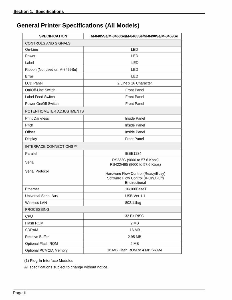
General Printer Specifications (All Models)
SPECIFICATION M-8485Se/M-8460Se/M-8465Se/M-8490Se/M-8459Se
CONTROLS AND SIGNALS On-Line LED Power LED
Label LED
Ribbon (Not used on M-8459Se) LED
Error LED
LCD Panel 2 Line x 16 Character
On/Off-Line Switch Front Panel
Label Feed Switch Front Panel
Power On/Off Switch Front Panel
POTENTIOMETER ADJUSTMENTS
Print Darkness Inside Panel
Pitch Inside Panel
Offset Inside Panel
Display Front Panel
INTERFACE CONNECTIONS (1)
Parallel IEEE1284
Serial
Serial Protocol
RS232C (9600 to 57.6 Kbps) RS422/485 (9600 to 57.6 Kbps)
Hardware Flow Control (Ready/Busy) Software Flow Control (X-On/X-Off)
Bi-directional
Ethernet 10/100BaseT
Universal Serial Bus USB Ver 1.1
Wireless LAN 802.11b/g
PROCESSING
CPU 32 Bit RISC
Flash ROM 2 MB
SDRAM 16 MB
Receive Buffer 2.95 MB
Optional Flash ROM 4 MB
Optional PCMCIA Memory 16 MB Flash ROM or 4 MB SRAM
(1) Plug-In Interface Modules
All specifications subject to change without notice.
Page iii
Section 1. Specifications
Character Fonts (All Models)
SPECIFICATION M-8485Se/M-8459Se/M-8460Se/M-8465Se M-8490Se MATRIX FONTS U Font (5 dots W x 9 dots H)
S Font
(8 dots W x 15 dots H)
M Font
(13 dots W x 20 dots H)
XU Font
(5 dots W x 9 dots H) Helvetica
XS Font (17 dots W x 17 dots H) Univers Condensed Bold
XM Font
(24 dots W x 24 dots H) Univers Condensed Bold
OA Font
(15 dots W x 22 dots H) OCR-A
(22 dots W x 33 dots H) OCR-A
OB Font
(20 dots W x 24 dots H) OCR-B
(30 dots W x 36dots H) OCR-A AUTO SMOOTHING FONTS
WB
WB Font (18 dots W x 30 dots H)
WL
WL Font (28 dots W x 52 dots H)
XB
XB Font (48 dots W x 48 dots H) Univers Condensed Bold
XL
XL Font (48 dots W x 48 dots H) Sans Serif VECTOR FONTS
Proportional or Fixed Spacing Font Size 50 x 50 dots to 999 x 999 dots
Helvetica, 10 Font Variations AGFA® RASTER FONTS
A Font
CG Times, 8 to 72 pt
B Font
CG Triumvirate, 8 to 72 pt DOWNLOADABLE FONTS
TrueType Fonts with Utility Program CHARACTER CONTROL
Expansion up to 12X in either the X or Y coordinates Character Pitch control
Line Space control Journal Print facility
0°, 90°, 180° and 270° Rotation
All specifications subject to change without notice.
Page iv

Section 1. Specifications
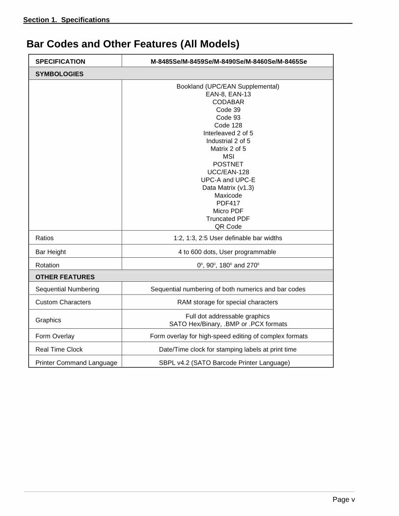
Bar Codes and Other Features (All Models)
SPECIFICATION M-8485Se/M-8459Se/M-8490Se/M-8460Se/M-8465Se
SYMBOLOGIES Bookland (UPC/EAN Supplemental)
EAN-8, EAN-13 CODABAR
Code 39 Code 93
Code 128 Interleaved 2 of 5 Industrial 2 of 5
Matrix 2 of 5 MSI
POSTNET UCC/EAN-128
UPC-A and UPC-E Data Matrix (v1.3)
Maxicode PDF417
Micro PDF Truncated PDF
QR Code
Ratios
1:2, 1:3, 2:5 User definable bar widths
Bar Height
4 to 600 dots, User programmable
Rotation
00, 900, 1800 and 2700
OTHER FEATURES
Sequential Numbering
Sequential numbering of both numerics and bar codes
Custom Characters
RAM storage for special characters
Graphics Full dot addressable graphics SATO Hex/Binary, .BMP or .PCX formats
Form Overlay
Form overlay for high-speed editing of complex formats
Real Time Clock
Date/Time clock for stamping labels at print time
Printer Command Language
SBPL v4.2 (SATO Barcode Printer Language)
Page v
Section 1. Overview and Specifications
Optional Accessories (All Models)
ACCESSORY M-8485Se/M-8459Se/M-8490Se M-8460Se/M-8465Se
MEMORY EXPANSION PCMCIA Memory Cards (up to 16MB Flash or 4MB SRAM) and 8MB Flash ROM. Can be used for Graphic File storage, print buffer expansion, format storage and downloaded TrueType fonts.
PARALLEL INTERFACE
IEEE1284 Bi-Directional Plug-In Interface Module.
SERIAL INTERFACE
High Speed RS-232C Plug-In Interface Module.
USB INTERFACE
Universal Serial Bus Plug-In Interface Module.
ETHERNET INTERFACE
10/100BaseT Plug-In LAN Interface Module.
CENTRONICS
CENTRONICS Interface Module.
WIRELESS LAN
802.11b/g Interface Module.
FACE-OUT LABEL SENSOR
Top-mounted sensor for reflective "I-Marks" printed on the face of the label.
N/A
All specifications subject to change without notice.
Page vi

SECTION 1 PRINTER OVERVIEW
INTRODUCTION
The SATO “Se” Print Engines are designed to be integrated into high-performance on-site labeling systems. All printer parameters are user programmable using the front panel controls and the DIP switches. All popular bar codes and 14 human-readable fonts, including a vector font, are resident in memory providing literally thousands of type styles and sizes.
The Operator’s Manual will help you understand the basic operations of the printer such as setup, installation, configuration, cleaning and maintenance.
The following information is presented in this section:
• General Printer Specifications
• Optional Accessories
SATO "Se" Print Engines Page 1-1

Section 1. Printer Overview
This page left intentionally blank.
Page 1-8 SATO "Se" Print Engines

SECTION 2 INSTALLATION
INTRODUCTION
This section of the manual has been written to help you install the SATO “Se” print engine modules and to get started as quickly as possible.
It is recommend to read each chapter in this manual before the installation or the use of the print modules.
INSTALLATION
Careful consideration must be given when selecting the location of the printer, especially to environmental considerations. To obtain optimum results from the SATO“S” print module, always try to avoid operation locations influenced by:
• Direct or bright sunlight, as this will make the label sensor less responsive and may cause the label to be sensed incorrectly.
• Locations which have extremes of temperature, as this can create electrical
problems on the circuits within the printer. • The installed location of the printer should ideally be in areas free from
dust, humidity and sudden vibrations.
CONSUMABLES
Always use SATO carbon ribbons or equivalent in the thermal transfer models. The use of incorrect materials may cause malfunctions of the printer and void the warranty.
SATO “Se” Print Engines Page 2-1

Section 2. Installation
DIMENSIONS
Note: The exact position of components may vary depending on model.
Width: 10.4 inches 265 mm
Depth: Depth M-8460S Only:
16.06 inches 417 mm17.8 inches 452 mm
Height: 11.8 inches 300 mm
M-8460S8.9"
227 mm7.08"
0.4" 10 mm
9.65"245 mm
8.8" 223 mm
180 mm
11.8"300 mm
4.6"
16.1"408 M-8460S
17.9" 452 mm
4.6"
117.5 mm 117.5 mm
11.8" 300 mm
10.4" 265 mm
10.4" 265 mm
9.25"235 mm
Right Hand Model Shown
Page 2-2 SATO “Se” Print Engines

Section 2. Installation
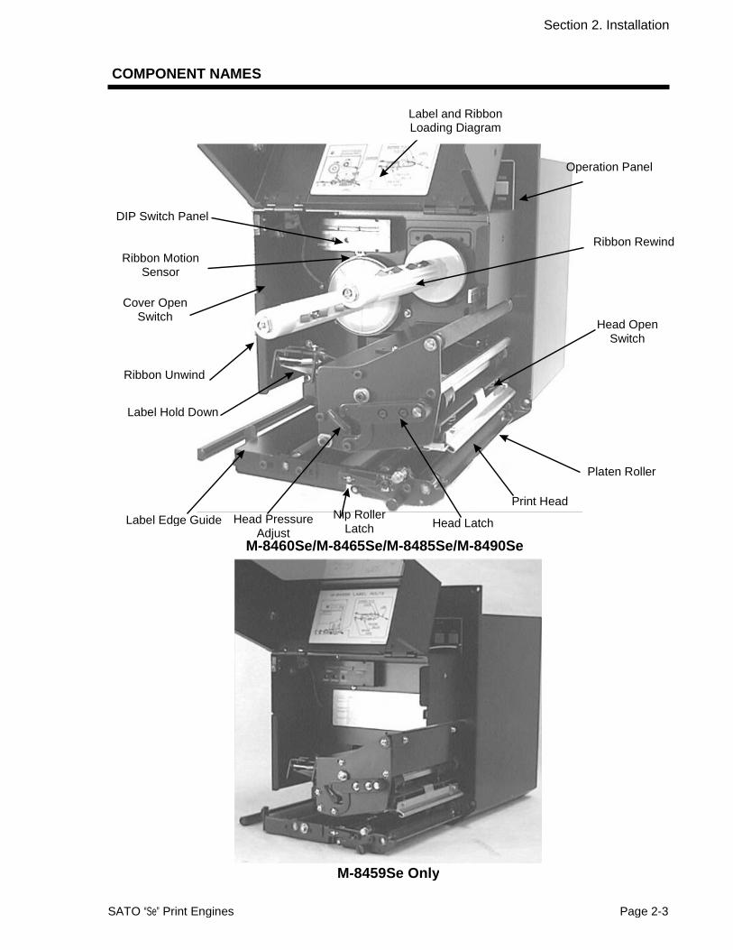
COMPONENT NAMES
Label and RibbonLoading Diagram
Operation Panel
DIP Switch Panel
Ribbon Motion Sensor
Ribbon Rewind
Cover Open Switch
Head OpenSwitch
Ribbon Unwind
Label Hold Down
Platen Roller
Label Edge Guide Head PressureAdjust
Nip RollerLatch Head Latch
Print Head
M-8460Se/M-8465Se/M-8485Se/M-8490Se
M-8459Se Only
SATO “Se” Print Engines Page 2-3
Section 2. Installation
REAR PANEL
EXT Connector
Memory Card Slot Cover
AC Fuse
Plug-In Interface Module
AC Input Connector
Power On/Off Switch To turn printer On or Off
Operation Panel To set up the various configurations and to display dispensing quantity and the various alarms.
Adjustment Panel Potentiometers (inside label compartment) to make setup adjustments.
AC Input Connector To input 115V 50/60 Hz. Use the power cable provided.
AC Fuse To protect the machine from abnormal power input. Type 15A/250V.
Interface Slot Slot for installation of Plug-In Interface Module.
EXT Connector This is an external signal connector for interfacing withthe label applicator system.
Memory Card Connectors for Optional PCMCIA Memory Cards.
Page 2-4 SATO “Se” Print Engines

Section 2. Installation
SWITCHES AND SENSORS
Cover Open Switch The printer mechanism cover is fitted with a microswitch. When the cover is opened, this switch is activated and the printer will stop printing.
Ribbon Motion Sensor The sensor will react to the carbon ribbon unwind whenapproximately 46 feet of ribbon remain. This sensor is a motion detector that signals the printer when the ribbon supply is turning. This sensor is used for both the ribbon end and ribbon near end sensing.
Note: The M-8459Se Direct Thermal print engine doesnot use a Ribbon Motion Sensor.
Head Open Switch When the print head is opened, this switch is activatedand the printer will stop printing.
Label Sensor This sensor unit contains two sensors for both labelgap and Eye-mark sensing.
SATO “Se” Print Engines Page 2-5
A note about LEFT HAND and RIGHT HAND modelsThe print engines are available in RIGHT HAND and LEFT HAND and models. In Right Hand
models, the label roll is loaded on the right-hand side of the printer, while the Left Hand models, the label roll is loaded on the left-hand side. However, models sold in the USA are named according to the direction of label feeding. Thus, Right Hand models feed the label from the left to the right, and Left Hand models load labels from the right to the left.

Section 2. Installation
MEDIA LOADING
Ribbon Loading (not applicable for the M-8459Se)
New Ribbon1. Open the print head by rotating the Head
Latch until the head releases. It is spring-loaded in the open position.
2. Place a new ribbon roll on the Ribbon Unwind Spindle and push it onto the spindle as far as it will go. Make sure the ribbon wil unwind from the top of the roll. Note that all SATO ribbons are wound face-in (the ink or dull side faces toward the inside of the roll).
3. Place an empty ribbon core on the RibbonWind Spindle and push it onto the spindleas far as it will go.
Empty Core
4. Unwind the clear ribbon leader until about 12 inches of leader/ribbon are off the roll.
5. Route the ribbon as shown in the Ribbon Routing Diagram on the inside of the cover.
6. Tape the end of the ribbon leader to the empty core so that it will go underneath the core and over the top (see diagram on inside of cover).
7. Manually wind approximately three turns of ribbon on the core.
8. Inspect the ribbon to make sure it is notfolded over or excessively wrinkled as itpasses over the print head.
9. If labels are already loaded, close and latch the print head.
Page 2-6 SATO “Se” Print Engines

Section 2. Installation
Loading the Label Stock
1. Open the print head by rotating the HeadLatch until the head releases. It is spring-loaded in the open position.
2. Unlatch the Label Hold Down by lifting up on the latch. It is spring-loaded in the open position.
3. Pull the Label Edge Guide all the way out.
4. Remove approximately 18 inches of labels from the backing liner.
5. Route the label liner under the Label Hold Down and under the print head and out the front of the printer.
6. Pull the liner through the printer until the
first label is positioned under the Label Hold Down.
Label Edge Guide
Label Hold Down
7. Push the labels in until they contact the inside edge of the printer, then position the Label Edge Guide until it lightly contacts the outside edge of the label liner.
8. Close and latch the Label Hold Down andPrint Head.
9. Release the Nip Roller Hold Down by rotating the Nip Roller Latch tab clockwise. The Nip Roller Hold Down will swing down. Label Hold Down
Closed Labels
10. Route the liner over the peel bar and back between the Nip Roller Hold Down and the Nip Roller.
11. Pull the liner tight. Close the Nip Roller Hold Down by pushing upward until it latches in place. Make sure the Nip Roller Latch is securely engaged.
Note: Always check that the backing paper istaut between Platen Roller and Nip Roller.
Nip RollerLatch
Nip Roller Hold Down
LabelLiner
PeelBar
SATO “Se” Print Engines Page 2-7

Section 2. Installation
12. Turn the printer on and press the Feed button. It should feed labels until the first label is peeled and ready for application.
Page 2-8 SATO “Se” Print Engines

Section 2. Installation
ADJUSTING THE LABEL SENSOR
The “Se” printers can position labels using either a label gap (transmissive) or anEye-Mark (reflective) sensor. The sensor used is selected by DSW2-2. The gap sensor position can be adjusted over a limited range. In addition, the signals from the sensors can be adjusted using the LCD panel to compensate for different liner opacities and/or Eye-Mark reflectance values.
Print Head
Maximum Width
Maximum Print Width
Gap Sensor Adjustment
Non-Printable Area
I-Mark on Back Side of Liner Minimum Width = 0.125" (3 mm)
Minimum Length = 0.5" (12 mm)
Max Label Width (includes liner)
M-8459Se M-8460/8465Se M-8485Se M-8490Se 5.27" (134 mm) 6.5“ (165 mm) 5.27" (134 mm) 5.27" (134 mm)
Max Print Width 4.4" (112 mm) 6.0" (152 mm) 5.0" (128 mm) 4.4" (112 mm)
Gap Sensor Adjustment Range
0.5" to 2.67"14 mm to 68 mm
0.5" to 3.25"14 mm to 82 mm
0.5" to 2.67" 14 mm to 68 mm
0.5" to 2.67"14 mm to 68 mm)
Non-Print Area 0.12" (3 mm) 0.12" or 0.25"3 mm or 6.5 mm
0.12" (3 mm) 0.12" (3 mm)
SATO “Se” Print Engines Page 2-9

Section 2. Installation
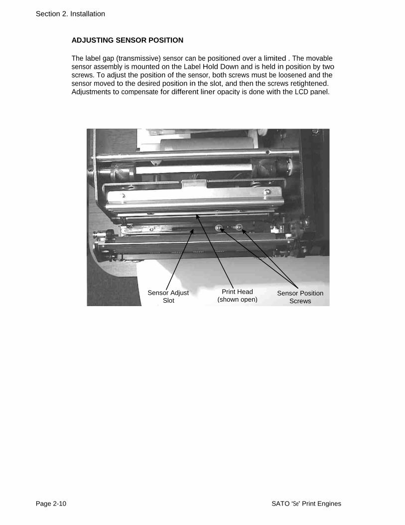
ADJUSTING SENSOR POSITION
The label gap (transmissive) sensor can be positioned over a limited . The movable sensor assembly is mounted on the Label Hold Down and is held in position by two screws. To adjust the position of the sensor, both screws must be loosened and the sensor moved to the desired position in the slot, and then the screws retightened. Adjustments to compensate for different liner opacity is done with the LCD panel.
Sensor AdjustSlot
Print Head(shown open)
Sensor Position Screws
Page 2-10 SATO “Se” Print Engines
Section 2. Installation
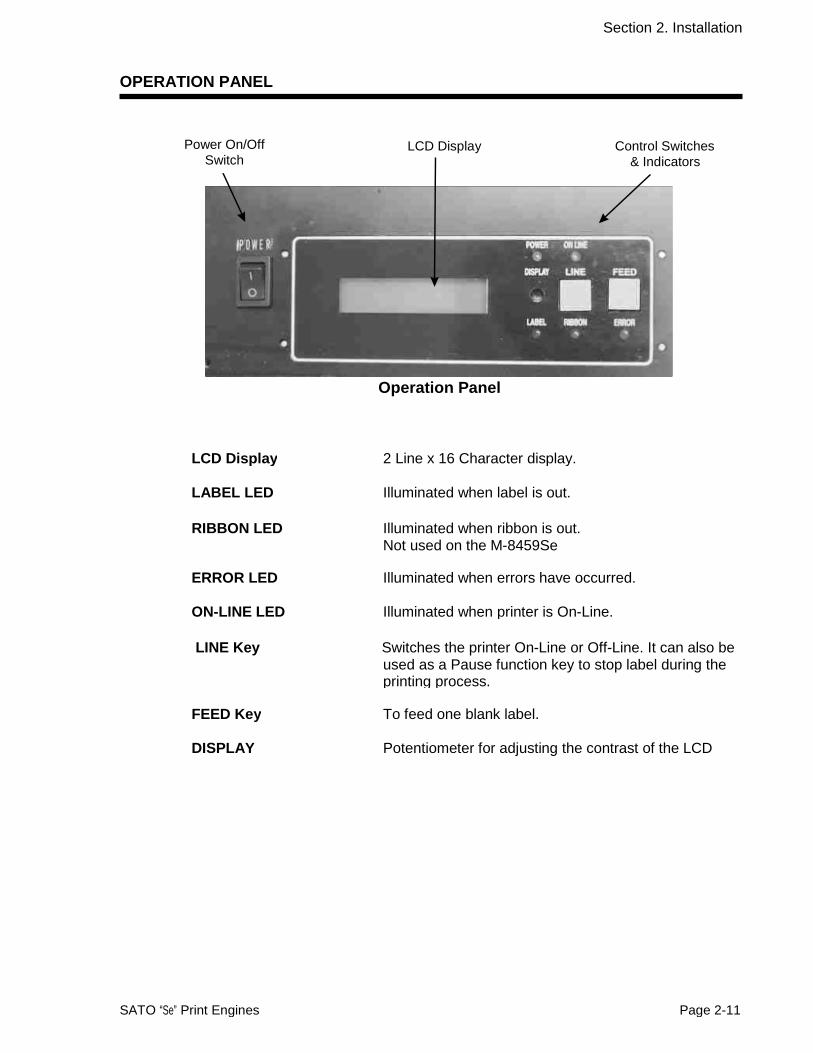
OPERATION PANEL
Power On/OffSwitch
LCD Display Control Switches& Indicators
Operation Panel
LCD Display 2 Line x 16 Character display.
LABEL LED Illuminated when label is out.
RIBBON LED Illuminated when ribbon is out. Not used on the M-8459Se
ERROR LED Illuminated when errors have occurred.
ON-LINE LED Illuminated when printer is On-Line.
LINE Key Switches the printer On-Line or Off-Line. It can also be used as a Pause function key to stop label during the printing process.
FEED Key To feed one blank label.
DISPLAY Potentiometer for adjusting the contrast of the LCD
SATO “Se” Print Engines Page 2-11
Section 2. Installation
DIP SWITCH PANEL
The DIP Switch panel is located inside the cover and contains three 8-position DIP switches and three adjustment potentiometers. Adjustment procedures for these are listed in Section 3: Configuration.
DIP Switches
Potentiomenters
Page 2-12 SATO “Se” Print Engines

DSW1-1 SETTING
SECTION 3 CONFIGURATION
PRINTER DIP SWITCH CONFIGURATION
DIP Switch Panels
There are two DIP switches (DSW2 and DSW3) located inside the cover. These switches can be used to set:
• Thermal transfer or direct thermal mode
• Label sensor enable/disable
• Head check mode
• Hex dump mode
• Single Job or Multi-Job Receive buffer
• Operation mode
In addition, a third DIP switch is located on the RS232C Serial Adapter card and is used to set the RS232C transmit/receive parameters
Each switch is an eight section toggle switch. The ON position is always to the top. To set the switches, first power the unit Off, then position the DIP switches. Finally, after placing the switches in the desired positions, power the printer back on. The switch settings are read by the printer electronics during the power up sequence. They will not become effective until the power is cycled.
RS232 Transmit/Receive Setting
Data Bit Selection (DSW1-1). This switch sets the printer to receive either 7 or 8bit data bits for each byte transmitted.
ON OFF
DSW1 1 2 3 4 5 6 7 8
Parity Selection (DSW1-2, DSW1-3). These switches select the type of parity used for error detection.
DSW1-2 DSW1-3 SETTING
ON OFF
DSW1 1 2 3 4 5 6 7 8
SATO “Se” Print Engines PN 9001073 Rev B Page 3-1
Off 8 data bitsOn 7 data bits
Off Off No Parity Off On Even On Off Odd On On Not Used

Section 3. Configuration
Stop Bit Selection (DSW1-4). Selects the number of stop bits to end each byte transmission.
DSW1-4 SETTING Off 1 Stop Bit
On 2 Stop Bits
ON OFF
DSW1 1 2 3 4 5 6 7 8
Baud Rate Selection (DSW1-5, DSW1-6). Selects the data rate (bps) for the RS232 port.
DSW1-5 DSW1-6 SETTING
Off Off 9600
Off On 19200
On Off 38400
On On 57600
ON OFF
DSW1 1 2 3 4 5 6 7 8
Protocol Selection (DSW1-7, DSW1-8). Selects the flow control and status reporting protocols. See Section 6: Interface Specifications for more information.
(* Will select the Status 2 protocol if DSW2-8 is ON)
DSW1-7 DSW1-8 SETTINGON OFF
DSW1 1 2 3 4 5 6 7 8
Printer Set Up
Print Mode Selection (DSW2-1). Selects between direct thermal printing on thermally sensitive paper and thermal transfer printing using a ribbon. Note: This switch is not used on the M-8459S.
DSW2-1 SETTING Off Therm XfrOn Direct Therm
ON OFF
DSW2 1 2 3 4 5 6 7 8
Sensor Type Selection (DSW2-2). Selects between the use of a label gap or a reflective Eye-Mark detector. See page 2-9 for the location of these sensors.
DSW2 DSW2-2 SETTING
Off Gap On Eye-Mark
ON OFF
1 2 3 4 5 6 7 8
Page 3-2 SATO “Se” Print Engines
Off Off Rdy/Bsy Off On Xon/Xoff On Off Bi-Com 3
On On Bi-Com 4*

Section 3. Configuration
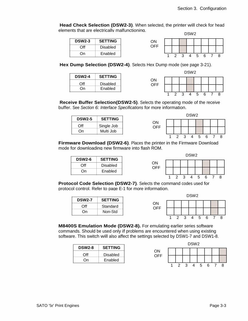
Head Check Selection (DSW2-3). When selected, the printer will check for head elements that are electrically malfunctioning.
DSW2-3 SETTING
Off DisabledON OFF
DSW2
On Enabled 1 2 3 4 5 6 7 8
Hex Dump Selection (DSW2-4). Selects Hex Dump mode (see page 3-21).
DSW2 DSW2-4 SETTING
ON OFF
1 2 3 4 5 6 7 8
Receive Buffer Selection(DSW2-5). Selects the operating mode of the receive buffer. See Section 6: Interface Specifications for more information.
DSW2 DSW2-5 SETTING
ON OFF
1 2 3 4 5 6 7 8Firmware Download (DSW2-6). Places the printer in the Firmware Download mode for downloading new firmware into flash ROM.
DSW2-6 SETTINGON OFF
DSW2 1 2 3 4 5 6 7 8
Protocol Code Selection (DSW2-7). Selects the command codes used for protocol control. Refer to page E-1 for more information.
DSW2-7 SETTINGON OFF
DSW2 1 2 3 4 5 6 7 8
M8400S Emulation Mode (DSW2-8). For emulating earlier series software commands. Should be used only if problems are encountered when using existing software. This switch will also affect the settings selected by DSW1-7 and DSW1-8.
DSW2 DSW2-8 SETTING
ON OFF
1 2 3 4 5 6 7 8
SATO “Se” Print Engines Page 3-3
Off DisabledOn Enabled
Off Single Job On Multi Job
Off Disabled On Enabled
Off Standard On Non-Std
Off Disabled On Enabled
Section 3. Configuration
Backfeed Sequence (DSW3-1). Backfeed is used to correctly position the label forapplication and then retract the next label to the proper print position. This operationcan be performed immediately after a label is printed and used, or immediately priorto the printing of the next label.
DSW3-1 SETTING
ON OFF
DSW3 1 2 3 4 5 6 7 8
Label Sensor Selection (DSW3-3). Enables or disables the Label Sensor. If the Sensor is enabled, it will detect the edge of the label and position it automatically. If it is disabled, the positioning must be under software control using Line Feed commands.
DSW3-3 SETTING ON OFF
DSW3 1 2 3 4 5 6 7 8
Back-Feed Selection (DSW3-4). When Back-Feed is enabled, the printer will position the last printed label for dispensing and retract it before printing the next label. The amount of backfeed offset is adjustable .
DSW3-4 SETTING
Off Enabled ON OFF
DSW3
On Disabled 1 2 3 4 5 6 7 8
External Signal Interface. See Section 6: Interface Specifications for information
EXT Print Start Signal Selection (DSW3-5). Allows an external device to initiate a label print for synchronization with the applicator. See Section 6: Interface Specifications for a description of the signal level and requirements When DSW3-5 is On, the unit is in the Continuous print mode, Backfeed is disabled and External Signals are ignored.
DSW3-5 SETTING ON OFF
DSW3 1 2 3 4 5 6 7 8
Page 3-4 SATO “Se” Print Engines
Off Before On After
Off Enabled On Disabled
Off Sensor Used On Not Used

Section 3. Configuration
External Signal Type Selection (DSW3-6, DSW3-7). Both the polarity and signal type (level or pulse) of the external print synchronizing signal can be selected. See page 6-19 for a definition of signal types.
DSW3-6 DSW3-7 SETTING
Off Off Type 4
Off On Type 3
On Off Type 2
On On Type 1
ON OFF
DSW3 1 2 3 4 5 6 7 8
Repeat Print via External Signal (DSW3-8). Allows the applicator to reprint the current label in the print buffer. See Section 6: Interface Specifications for a description of the signal requirements.
DSW3-8 SETTING
Off Disabled
On Enabled
ON OFF
DSW3 1 2 3 4 5 6 7 8
SATO “Se” Print Engines Page 3-5

Section 3. Configuration
DEFAULT SETTINGS
SWITCH SELECTIONS
All switches are placed in the Off default position for shipping. This will result in the following operating configuration:
Communications: Protocol: Sensor: Receive Buffer: Mode: Label Sensor: Backfeed: External Signals:
8 data bits, no parity, 1 Stop bit, 9600 Baud Ready/Busy Gap Sensor Multi Job Batch/continuous Sensor Used Enabled Enabled
SOFTWARE DEFAULT SETTINGS
The printer stores the software settings upon receipt and uses them until they are again changed by receipt of a command containing a new setting. These settings are stored in non-volatile memory and are not affected by powering the printer off. The printer may be reset to use the default software settings by depressing the LINE and FEED keys simultaneously while powering the printer on. This will result in the following default configuration:
M-8459Se M-8460/8465Se M-8485Se M-8490Se Print Darkness 3 2 2 2
Print Speed 4 in. per sec. 6 in. per sec. 6 in. per sec. 6 in. per sec.
Print Reference Vertical = 0000, Horizontal = 0000 Zero Slash Auto On Line Enabled
Once the default operation is completed, a DEFAULT COMPLETED message will be displayed on the LCD panel. The printer should be powered off while this message is being displayed (or after the beep is heard. This saves the default settings in the non-volatile memory where they will be automatically loaded the next time the printer is powered on.
DEFAULT COMPLETED
Page 3-6 SATO “Se” Print Engines
Section 3. Configuration
POTENTIOMETER ADJUSTMENTS
PITCH
After the pitch has been set with the LCD Control Panel, it is sometimes desirable to make minor adjustments. This can be done using the PITCH potentiometer on the front panel. This potentiometer is set at the factory so that it has a range of +/- 3.75 mm. The midpoint setting should have no effect on the pitch. Turning the potentiometer all the way clockwise should move the print position 3.75 mm up towards the top edge of the label. Turning it all the way counterclockwise should move the print position down 3.75 mm.
1. While depressing the FEED key on the front panel, power the printer on.
2. When you hear one beep from the printer, release the FEED key and the printerwill display on the LCD panel a message asking what type of Test Label you wantto print.
3. Use the LINE key to step to the Configuration selection and press the FEED key to accept the selection.
4. Use the LINE key to select the Test Label Size. After the size is selected, press the FEED key to accept the selection and the printer will begin to print test labels continuously.
5. Adjust the PITCH potentiometer on the front panel until the first print position is at the desired location on the label. If the potentiometer does not have enough range, then you will have to change the pitch setting using the front panel display.
6. Press the FEED key to stop the printer.
7. To exit the Test Label mode, power the printer off andthen back on.
Adjusting the PITCH potentiometer will affect the stop position of the label.
BACKFEED OFFSET
When a label is printed it must be correctly positioned for dispensing and application. The Backfeed adjustment is used to position the label so that it is fully dispensed and ready for application. It may then be necessary to reposition the next label before printing. The Backfeed (repositioning of the label) operation is enabled if DSW3-4 is in the Off position. If Backfeed is enabled, placing DSW3-1 is in the Off position will cause the backfeed operation to be performed immediately before each label is printed. If DSW3-1 is in the On position, the backfeed operation is performed as soon as the dispensed label has been printed and taken from the printer.
The amount of backfeed is controlled by the OFFSET potentiometer on the DIP Switch Panel inside the cover. When turned all the way counterclockwise, the amount of backfeed is +3.75 mm, and -3.75 mm when turned all the way counterclockwise.
1. Turn the printer on.
SATO “Se” Print Engines Page 3-7

Section 3. Configuration
2. Press the LINE key to place the printer in the Off Line status.
3. Press the FEED key to feed out a blank label.
4. Adjust the position using the OFFSET potentiometer on the front control panel and feed another label by depressing the FEED key. Repeat this procedure until the label is fully released from the liner.
DISPLAY
This potentiometer is used to adjust the contrast of the LCD display for optimum viewing under various lighting conditions.
The PRINT potentiometer is used to adjust the amount of heat (i.e., power) applied to the head for printing. It provides a continuous range of adjustment. Maximum print darkness is obtained by turning the potentiometer all the way clockwise and a maximum counterclockwise setting will give the lightest print.
NOTE: The PRINT potentiometer adjustment will affect the darkness in all of the command code speed and darkness ranges.
Page 3-8 SATO “Se” Print Engines

Section 3. Configuration
LCD PANEL PRINTER CONFIGURATION
The LCD Panel is used by the operator in conjunction with the LINE and FEED switches to manually enter printer configuration settings. Many of these settings can also be controlled via software commands and in the case of conflict between software and control panel settings, the printer will always use the last valid setting. Ifyou load a label job that includes software settings and then enter a new setting via the LCD panel, the manually set values will be used by the printer. If you set the values manually and then download a job with software settings, the software settingswill be used.
There are seven modes of operation. To enter the desired mode, the KEY SEQUENCE combination listed in the table below must be performed. The initial LCD display message is shown for each mode.
MODE KEY SEQUENCE INITIAL DISPLAY PAGE
Normal POWER ONLINE QTY:000000
Advanced LINE + POWER ADVANCED MODE
Test Print FEED + POWER TEST PRINT MODE CONFIGURATION
Default Setting LINE + FEED + POWER DEFAULT SETTING YES NO
Clear Non-Standard Protocol DSW2-7 ON + LINE + FEED+ POWER
ALT. PROTOCOL
Protocol Code Download DSW2-7 ON + POWER USER DOWNLOAD
Hex Dump of buffer DSW2-4 ON + POWER ONLINE QTY:000000
SATO “Se” Print Engines Page 3-9
Flash Download DSW2-6 ON FLASH DOWNLOAD READY
DEFAULT COMPLETE
Boot Download DSW2-6 ON + FEED BOOT DOWNLOADER +LINE + POWER PRESS FEED KEY
Hidden DSW2-4 ON + FEED HIDDEN MODE + POWER

Section 3. Configuration
NORMAL MODE
The printer initially powers on in the ONLINE mode. The user can access the User Settings using the following procedures.
V 05.A4.01.02 INITIALIZING
Displays the firmware during the initialization.
ONLINE QTY:000000
OFFLINE
000000 PRINT DARKNESS
1(L) 2(M) 3(H) PRINT SPEED
4 6 8 10 12
The LCD will display the ONLINE status on the top line and the bottom line will contain the label quantity (QTY) status. The messsge will be changed to OFFLINE whenever the printer is switched offline by pressing the LINE key. As soon a print job is received, the quantily line will indicate the number of labels to be printed. As soon as the label job begins to print, the display will indicate the number of labels in the print job that remains to be printed.
Press the LINE key once. When the display changes to OFFLINE, press the FEED and LINE keys simultaneously for more than one second.
The LCD now displays the Print Darkness selections. The current setting is indicated by a cursor over one of the range settings. There are 3 possible selections (except for the M-8459Se which has 5 possible selections). The lowest setting represents the lightest print and the highest setting the darkest print.
1. Press the LINE key to step the cursor to the desired setting.
2. Once the correct setting is underlined, press the FEED key to accept the selection and step the display to the next adjustment.
The print speed selections are dependent upon the printer model. The current setting is indicated by the underline cursor.
1. Use the LINE key to step the cursor to the desired setting.
2. Once the correct setting is selected, press the FEED key to accept the selection and step the display to the next adjustment.
M-8459Se M-8485Se M-8460Se/8465SeM-8490Se
2 ips 4 ips 4 ips
3 ips 6 ips 6 ips
4 ips 8 ips 8 ips
5 ips 10 ips
12 ips
Page 3-10 SATO “Se” Print Engines

Section 3. Configuration
PITCH OFFSET + 00mm
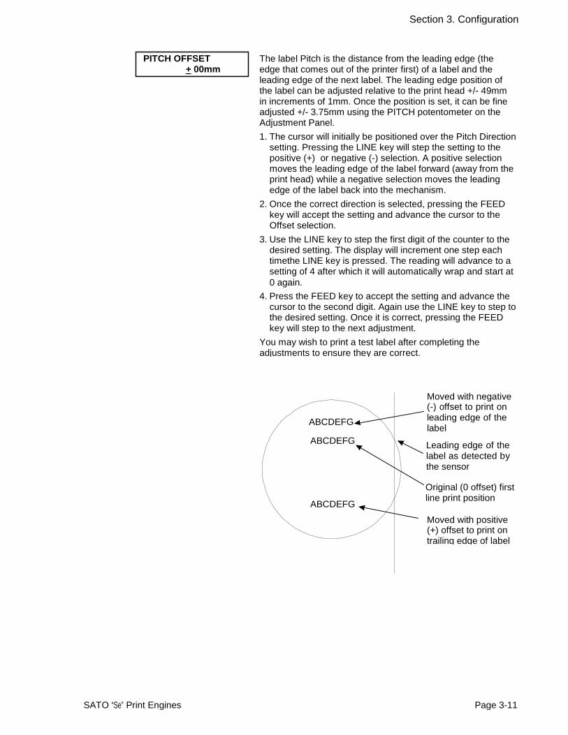
The label Pitch is the distance from the leading edge (the edge that comes out of the printer first) of a label and the leading edge of the next label. The leading edge position of the label can be adjusted relative to the print head +/- 49mm in increments of 1mm. Once the position is set, it can be fine adjusted +/- 3.75mm using the PITCH potentometer on the Adjustment Panel.
1. The cursor will initially be positioned over the Pitch Direction setting. Pressing the LINE key will step the setting to the positive (+) or negative (-) selection. A positive selection moves the leading edge of the label forward (away from the print head) while a negative selection moves the leading edge of the label back into the mechanism.
2. Once the correct direction is selected, pressing the FEED key will accept the setting and advance the cursor to the Offset selection.
3. Use the LINE key to step the first digit of the counter to the desired setting. The display will increment one step each timethe LINE key is pressed. The reading will advance to a setting of 4 after which it will automatically wrap and start at 0 again.
4. Press the FEED key to accept the setting and advance the cursor to the second digit. Again use the LINE key to step to the desired setting. Once it is correct, pressing the FEED key will step to the next adjustment.
You may wish to print a test label after completing the adjustments to ensure they are correct.
ABCDEFG ABCDEFG
Moved with negative(-) offset to print on leading edge of the label
Leading edge of the label as detected by the sensor
ABCDEFG
Original (0 offset) firstline print position Moved with positive (+) offset to print on trailing edge of label
SATO “Se” Print Engines Page 3-11
CANCEL PRINT JOB YES NO
CANCEL PRINT JOB
CURRENT ALL
If the printer has a print job(s) in memory, selecting YES will cause the job(s) to be cleared. The default selection is NO. Be sure you want to cancel the print job(s) before selecting yes as the job(s) cannot be recovered and will have to be retransmitted tyo the printer.
1. Use the LINE key to step the cursor to either the YES or NO selection.
2. Next, you can select Current to cancel the current print job. If not print job is currently in process, the next print job will be cancelled. Selecting ALL cancels all queued print jobs (if any).
3. Once the correct setting is selected, pressing the FEED key will accept the setting.
4. After the print job(s) have been cleared from memory, the printer will display a COMPLETED message for 3 seconds and then return to the initial ONLINE Normal Mode.
5. If you wish to change any of the settings, you must enter the User Settings mode again by taking the printer OFFLINE and pressing the LINE and FEED keys.
SEND BACK DATA YES NO
This function is valid when the printer buffer has been set to operate on a single-item basis, where each print job is processed one at a time. DSW2-5 must be set to ON for this mode. Use the LINE key to select YES or NO (default), followed by pressing the FEED key to confirm the selection. If this function is set to YES, then the printer will, in the event of a printing error and taken OFFLINE, send back the most recent print job data processed/printed, back to the host for verification. This is useful for diagnosing programming errors. When data sendback happens, the TRANSMITTING message appears, followed by a COMPLETED message upon successful sending of the print job data back to the host computer.
SEND BACK DATA TRANSMITTING
SEND BACK DATA COMPLETED
CANCEL PRINT JOB COMPLETED
Page 3-12 SATO “Se” Print Engines

Section 3. Configuration
ADVANCED MODE
An Advanced Mode is provided to make adjustments that require only occasional changes. Since they affect the basic operation of the printer, the procedure for entering this mode is designed to prevent someone from accidently changing the settings.
ADVANCED MODE The Advance Mode is entered by pressing the LINE key whilesimultaneously turning power on. The printer will emit one longbeep after which the LINE key is released.
ZERO SLASH YES NO
AUTO ONLINE
YES NO
This setting determines if a zero is printed with a slash or without a slash. This setting can also be controlled via software commands. When YES is selected (default), the printer internal fonts will have a slash through the center of the zero character.
1. Use the LINE key to step the cusor to either the YES or NO selection.
2. Once the correct setting is selected, pressing the FEED key will accept the setting and advance the display to the Auto Online display.
This setting determines the mode in which the printer powers up. If the YES selection is made, the printer powers up in the ON LINE mode and is ready to print. If NO is selected, the printer powers up in the OFF LINE mode and must be manually placed in the ON LINE mode by pressing the LINE key before it is ready to print.
1. Use the LINE key to step the cursor to either the YES (default) or NO selection.
2. Once the correct setting is selected, pressing the FEED key will accept the setting and advance the display to the Print Offset display.
SATO “Se” Print Engines Page 3-13
DARKNESS RANGE A B The Advance Mode is entered by pressing the LINE key while
simultaneously turning power on. The printer will emit one long

Section 3. Configuration
PRINT OFFSET V:+0000 H:+0000
Vertical Offset is the distance down from the leading edge (the edge of the label that comes out of the printer first) to the first vertical print position. A positive setting moves the label edge out of the printer while making it negative moves it bsack into the printer. Horizontal Offset is distance that the label image is shifted either to the right or left on the label. The image is shifted to the left (towards the inside edge of the label) for a positive setting and it is shifted to the right (towards the outside edge of the label) for a negative setting. This setting changes the base reference point for all subsequent label jobs. It’s effect is identical to the <ESC>A3 Base Reference point command. Since the printer moves the label in discrete steps equal to the size of the print dot, the units of measure for Vertical and Horizontal Offset distance is dots. The maximum values that can be set for each is +/-800.
1. Use the LINE key to step the counter to the desired setting. The display will increment one step for each time the LINE key is pressed. If the LINE key is held pressed for more than two seconds, it will automatically go into the fast scroll mode. The reading will advance to the maximum setting of 800 after which it will automatically wrap and start at “000” again. The range
2. Once the setting is correct, pressing the FEED key will accept the setting and advance to the next display.
Note: This setting can be overriden by the Base ReferencePoint Command.
HEAD DOT DENSITY 100 150 300
CALENDAR CHECK
YES NO
This selection only appears on the M-8490Se and M-8465Se when the DSW2-8 = On, and a 300dpi print head has been installed. It allows the user to select the print density.
1. Use the LINE key to step the underline cursor to the desired selection.
2. Once the underline cursor is under the desired selection, pressing the FEED key will accept the setting and advance the display
If the optional calender chip has been installed in the printer, this menu appears. The default is No. Similarly, the Set Calendar appears (if the chip is installed) allowing the date and time to be set manually using the LCD Display or via the <ESC>WT Calendar Set command. The last setting, set either manually via software command, received by the printer will be the value used. The format of the display is YY/MM/DD hh:mm (Year/Month/Day/hours:minutes).The date format is fixed and cannot be changed.
To set the Calendar, press the LINE key until the cursor is over YES. If the Calendar feature is to be disabled, press the LINE key until the cursor is underneath NO. When the desired setting is selected, press the FEED key.
Page 3-14 SATO “Se” Print Engines
SET CALENDAR
YES NO

Section 3. Configuration
CALENDAR 00/00/00 00:00
IGNORE CR/LF
YES NO
CHARACTER PITCH
PROP FIXED
1. Year - The first display shown will have the cursor over the two digit year selection. You can scroll through the dates by pressing the LINE key. The year number will increase by one each time the LINE key is pressed until it reaches its maximum legal value (i.e., “99” for the year digits) at which point it will wrap around to the “00” setting.
2. Month - After you have set the correct year, pressing the FEED key will advance the cursor to the two digit Month position. You can scroll through the numbers corresponding to the month by pressing the LINE key. The month number will increase by one each time the LINE key is pressed until it reaches a value of “12” at which point it will wrap around to the “01” setting.
3. Day - After you have set the correct month, pressing the FEED key will advance the cursor to the two digit Day position. You can scroll through the numbers corresponding to the month date by pressing the LINE key. The date number will increase by one each time the LINE key is pressed until it reaches a value of “31” at which point it will wrap around to the “01” setting.
4. Hour - After you have set the correct date, pressing the FEED key will advance the cursor to the two digit Hour position. You can scroll through the numbers corresponding to the hour (using a 24 hour clock) by pressing the LINE key. The hour number will increase by one each time the LINE key is pressed until it reaches a value of “24” at which point it will wrap around to the “01” setting.
5. Minute- After you have set the correct hour, pressing the FEED key will advance the cursor to the two digit Minute position. You can scroll through the numbers corresponding to the hour by pressing the LINE key. The minute number will increase by one each time the line key is pressed until it reaches a value of “60” at which point it will wrap around to the “01” setting.
6. After you have set the minutes, pressing the FEED key will accept the setting and advance to the Ignore CR/LF selection.
This selection tells the printer to strip out all carriage return/line feed pairs (CRLF ) from the data stream, including graphics and 2D bar codes. It is used primrily to maintain compatibility with earlier models of SATO printers.
1. Use the LINE key to step the underline cusor to either the YES or NO (default) selection.
2. Once the correct setting is underlined, pressing the FEED key will accept the setting and advance the display to the Character Pitch display.
This selection allows you to set the default character pitch to either fixed character spacing or proportional character (default) spacing.
1. Use the LINE key to step the cursor to the desired setting.
2. Once the correct setting is selected, pressing the FEED key will accept the setting and the display will return to the Advanced Mode display.
SATO “Se” Print Engines Page 3-15

Page 3-16 SATO “Se” Print Engines
Section 3. Configuration
ADVANCED MODE The menu cycles back to the start screen of the Advanced Mode. To exit this mode, turn the printer OFF and then ON again.
HEAD CHECK NORMAL BARCODE MODE SELECT XML SBPL
STORAGE MEDIA CARD ROM (INT)
This function causes the printer to perform a check of the print head when printing either normal text/graphics or when printing barcodes only. Select Barcode if you wish to use barcodes for the head check. Otherwise, select Normal.
Use this menu to select whether the printer will be supporting the SBPL (default) printer language, or XML, which is the standard language for Oracle and SAP systems.
Use this menu to choose whether to store user data in the memory card or in the printer’s internal memory. If the XML option was selected in the previous menu, this function will automatically format the memory storage area.
When XML data is received, it will be stored in the area select ed by the command CC1 or CC2.
The default setting is CARD.

CARD MODE
The Card Mode allows the operator to manage the Expanded Memory (PCMCIA Card or Internal Expanded Flash ROM).
V 05.A4.01.02 INITIALIZING
Displays the firmware during the initialization.
ADVANCED MODE The Card Mode is entered from the Advanced Mode display by pressing the LINE key once.
CARD MODE The Card Mode display indicates that the printer is in the CardMode. To advance to the first selection, press the FEED key.
MEM SELECT (CC1) CARD MEMORY
CARD->MEMORYCOPY
TRUETYPEFONT Y/N COPY START
YES NO TRUETYPEFONTCOPY
COPYING
This selection determines which type of optional expanded memory will be addressed as “CC1" in the command streams.The CARD selection specifies the optional PCMCIA card as CC1 and the optional Expanded Flash ROM as CC2. The Memory selection specifies the optional Expanded Flash ROM as CC1 and the optional PCMCIA card as CC2.
1. Step the cursor to the desired selection using the LINE key.
2. Once the cursor is positioned over the desired selection, press the FEED key to accept the selection and advance the display.
This selection allows you to copy TrueType fonts from the PCMCIA Memory card installed in the Memory Card slot on the rear of the printer to the optional Flash ROM.
1. Use the LINE key to step the cursor to desired setting. If Yes is selected, the printer will enter the Card Copy mode. If No is selected, the display will advance to the Card to Memory SATO Font Copy mode.
2. Confirm your selection by stepping the cursor to the Yes selection. If you select No, the display will return to the previous selection.
3. Press the FEED key to accept the selection. If Yes was selected the copy process will start.
TRUETYPE FONTCOPY COMPLETED
4. Once the copy process is completed, press the FEED key to step the display.
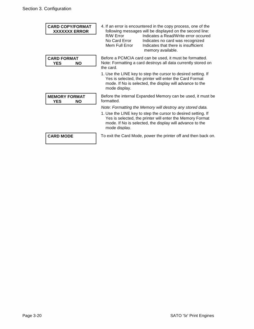
CARD COPY/FORMAT XXXXXXX ERROR
5. If an error is encountered in the copy process, one of the following messages will be displayed on the second line: R/W Error Indicates a Read/Write error occured No Card Error Indicates no card was recognized Mem Full Error Indicates that there is insufficient
memory available.
SATO “Se” Print Engines Page 3-17

Section 3. Configuration
CARD->MEMORYCOPY SATOFONT Y/N COPY START
YES NO SATO FONT COPY
COPYING
This selection allows you to copy SATO fonts from the PCMCIA Memory card installed in the Memory Card slot on the rear of the printer to the optional Flash ROM.
1. Use the LINE key to step the cursor to desired setting. If Yes is selected, the printer will enter the Card Copy mode. If No is selected, the display will advance to the Card to Memory Copy All mode.
2. Confirm your selection by stepping the cursor to the Yes selection. If you select No, the display will return to the previous selection.
3. Press the FEED key to accept the selection. If Yes was selected the copy process will start
SATO FONT COPY COMPLETED
4. Once the copy process is completed, press the FEED key to step the display.
CARD COPY/FORMAT XXXXXXX ERROR
CARD->MEMORYCOPY
ALL Y/N COPY START
YES NO CARD->MEMORY
COPYING
5. If an error is encountered in the copy process, one of the following messages will be displayed on the second line: R/W Error Indicates a Read/Write error occured No Card Error Indicates no card was recognized Mem Full Error Indicates that there is insufficient
memory available.
This selection allows you to copy the entire contents from the PCMCIA Memory card installed in the Memory Card slot on the rear of the printer to the optional internal Expanded Memory.
1. Use the LINE key to step the cursor to desired setting. If Yes is selected, the printer will enter the Card Copy mode. If No is selected, the display will advance to the Card to Memory Copy All mode.
2. Confirm your selection by stepping the cursor to the Yes selection. If you select No, the display will return to the previous selection.
3. Press the FEED key to accept the selection. If Yes was selected the copy process will start
CARD-.MEMORYCOMPLETED
4. Once the copy process is completed, press the FEED key to step the display.
CARD COPY/FORMAT XXXXXXX ERROR
MEMORY->CARDCOPY
ALL <0MB> Y/N
5. If an error is encountered in the copy process, one of the following messages will be displayed on the second line: R/W Error Indicates a Read/Write error occured No Card Error Indicates no card was recognized Mem Full Error Indicates that there is insufficient
memory available.
This selection allows you to copy the entire contents of the optional Expanded Memory to the PCMCIA Memory card installed in the Memory Card slot on the rear of the printer.
1. Use the LINE key to step the cursor to desired setting. If Yes is selected, the printer will enter the Card Copy mode. If No is selected, the display will advance to the Card to Memory Copy All mode.
Page 3-18 SATO “Se” Print Engines

Section 3. Configuration
COPY START YES NO
MEMORY->CARDCOPY
COPYING
2. Confirm your selection by stepping the cursor to the Yes selection. If you select No, the display will return to the previous selection.
3. Press the FEED key to accept the selection. If Yes was selected the copy process will start
MEMORY->CARDCOPYCOMPLETED
4. Once the copy process is completed, press the FEED key to step the display.
CARD COPY/FORMAT XXXXXXX ERROR
CARD->MEMORYCOPY
PROGRAM Y/N COPY START
YES NO CARD->MEMORY
COPY COPYING
5. If an error is encountered in the copy process, one of the following messages will be displayed on the second line: R/W Error Indicates a Read/Write error occured No Card Error Indicates no card was recognized Mem Full Error Indicates that there is insufficient
memory available.
This selection allows the user to copy printer firmware from the PCMCIA Memory Card to the printer.
1. Use the LINE key to step the cursor to desired setting. If Yes is selected, the printer will enter the Card Copy mode. If No is selected, the display will advance to the mode display.
2. Confirm your selection by stepping the cursor to the Yes selection. If you select No, the display will return to the previous selection.
3. Press the FEED key to accept the selection. If Yes was selected the copy process will start
CARD->MEMORYCOPYCOMPLETED
4. Once the copy process is completed, press the FEED key to step the display.
CARD COPY/FORMAT XXXXXXX ERROR
MEMORY->CARDCOPY
PROGRAM Y/N COPY START
YES NO MEMORY->CARDCOPY
COMPLETED
5. If an error is encountered in the copy process, one of the following messages will be displayed on the second line: R/W Error Indicates a Read/Write error occured No Card Error Indicates no card was recognized Mem Full Error Indicates that there is insufficient
memory available.
This selection allows the user to copy the current firmware installed in the printer to a PCMCIA Memory Card.
1. Use the LINE key to step the cursor to desired setting. If Yes is selected, the printer will enter the Card Copy mode. If No is selected, the display will advance to the mode display.
2. Press the FEED key to accept the selection. If Yes was selected the copy process will start. If you select No, the display will return to the previous selection.
3. Once the copy process is completed, press the FEED key to step the display.
SATO “Se” Print Engines Page 3-19

Section 3. Configuration
CARD COPY/FORMAT XXXXXXX ERROR
CARD FORMAT
YES NO MEMORY FORMAT
YES NO
4. If an error is encountered in the copy process, one of the following messages will be displayed on the second line: R/W Error Indicates a Read/Write error occured No Card Error Indicates no card was recognized Mem Full Error Indicates that there is insufficient
memory available.
Before a PCMCIA card can be used, it must be formatted. Note: Formatting a card destroys all data currently stored on the card.
1. Use the LINE key to step the cursor to desired setting. If Yes is selected, the printer will enter the Card Format mode. If No is selected, the display will advance to the mode display.
Before the internal Expanded Memory can be used, it must be formatted.
Note: Formatting the Memory will destroy any stored data. 1. Use the LINE key to step the cursor to desired setting. If
Yes is selected, the printer will enter the Memory Format mode. If No is selected, the display will advance to the mode display.
CARD MODE To exit the Card Mode, power the printer off and then back on.
Page 3-20 SATO “Se” Print Engines
SERVICE MODE
The Service Mode allows the operator to set up the basic operation parameters of the printer.
V 05.A4.01.02 INITIALIZING
Displays the firmware during the initialization.
ADVANCED MODE The Service Mode is entered from the Advanced Mode display by pressing the LINE key once.
SERVICE MODE The Service Mode display indicates that the printer is in the Card Mode. To advance to the first selection, press the FEED key.
GAP [X.XXV] INPUT
The “Se” Series printers determine the location of the leading edge of the label by measuring the difference between light levels when it sees either a label edge or a black “EYE” mark. This adjustment allows you to manually set the threshold voltage level, between the maximum and minimum light levels. DIP switch DSW2-2 selects the sensor type. If DSW2-2 is in the OFF position, the setting will be for a See-Thru (or Gap) sensor and the LCD will display “GAP” on the top line along with the current setting. If DSW2-2 is in the ON position, the LCD will display “EYE” on the top line with its current setting. If the value entered for the bottom line setting is “0.0V”, then the printer will automatically calculate the setting when the first label is fed after the printer is powered on or the head is closed. There are some instances where the automatically calculated value must be adjusted to ensure reliable label feeding, such as when the backing opacity or the reflectance of the EYE mark varies significantly within a roll of labels or between label rolls. In these instances the value should be set using the following procedures.
GAP [X.XXV] INPUT
GAP - When setting the “gap” threshold, the voltage shown on the top line of the display must be measured with nothing but the backing in the sensor and then again with a label still attached to the backing. The formula to be used for setting the threshold is:
(High Voltage Level + Low Voltage Level) x 0.5 = Start Value 1. Insert a label still attached to the backing into the sensor
and close the Label Hold-Down. Record the voltage shown on the top line of the LCD panel. This line should have the message “GAP” on the top line (DIP switch DSW2-2 = OFF). Make sure the label is all the way under the sensor.
2. Strip the label from the backing and insert the backing strip under the sensor and close the Label Lid. Record the voltage shown on the top line of the LCD panel. The voltage ranges measured should be within the following ranges:
Backing with label = 2.0V to 3.5V Backing without label = Less than 1.0V
If the measured values are outside this range, you may have trouble in finding a value that will work properly under all conditions. If this is the case, a higher quality label may be needed to get adequate performance.
SATO “Se” Print Engines Page 3-21

Section 3. Configuration
3. Calculate the starting point voltage using the formula.
4. Use the LINE key to step the counter to the desired setting. The display will increment one step for each time the LINE key is pressed. If the LINE key is held pressed for more than two seconds, it will automatically go into the fast scroll mode. The reading will advance to a setting of 4.9 (the maximum voltage) after which it will automatically wrap and start at “0.0” again. If a value of “0.0” is set, the printer will automatically set the level each time the printer is powered on with labels loaded and the head is closed.
5. Once the setting iscorrect, pressing the FEED key will accept the setting and advance the next display.
Page 3-22 SATO “Se” Print Engines
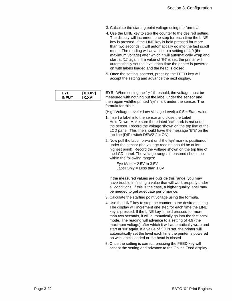
EYE [X.XXV] INPUT [X.XV]
EYE - When setting the “eye” threshold, the voltage must be measured with nothing but the label under the sensor and then again withthe printed “eye” mark under the sensor. The formula for this is:
(High Voltage Level + Low Voltage Level) x 0.5 = Start Value
1. Insert a label into the sensor and close the Label Hold-Down. Make sure the printed “eye” mark is not under the sensor. Record the voltage shown on the top line of the LCD panel. This line should have the message “EYE” on the top line (DIP switch DSW2-2 = ON).
2. Now pull the label forward until the “eye” mark is positioned under the sensor (the voltage reading should be at its highest point). Record the voltage shown on the top line of the LCD panel. The voltage ranges measured should be within the following ranges:
Eye-Mark = 2.5V to 3.5V Label Only = Less than 1.0V
If the measured values are outside this range, you may have trouble in finding a value that will work properly under all conditions. If this is the case, a higher quality label may be needed to get adequate performance.
3. Calculate the starting point voltage using the formula.
4. Use the LINE key to step the counter to the desired setting. The display will increment one step for each time the LINE key is pressed. If the LINE key is held pressed for more than two seconds, it will automatically go into the fast scroll mode. The reading will advance to a setting of 4.9 (the maximum voltage) after which it will automatically wrap andstart at “0.0” again. If a value of “0.0” is set, the printer will automatically set the level each time the printer is powered on with labels loaded or the head is closed.
5. Once the setting is correct, pressing the FEED key will accept the setting and advance to the Online Feed display.
Section 3. Configuration
AUTO ONLINE FEED YES NO
FEED ON ERROR
YES NO
This selection specifies whether or not the printer will feed a label when it is placed in the Online mode.
1. Use the LINE key to step the cursor to desired setting. If Yes is selected, the printer will feed a blank label anytime it enters the Online mode. If No (default) is selected, the display will advance to the mode display.
This selection specifies whether or not the printer will feed a label when an error condition is cleared..
1. Use the LINE key to step the cursor to desired setting. If Yes is selected, the printer will feed a blank label anytime an error condition is cleared. If No (default) is selected, the display will advance to the mode display.
SATO “Se” Print Engines Page 3-23
REPRINT W/FEED YES NO
This selection specifies whether or not the printer will print the last printed label stored in memory when the FEED key is pressed in the Normal Online mode.
1. Use the LINE key to step the cursor to desired setting. If Yes is selected, the printer will reprint the last label when the FEED key is pressed when the printer is Online. If the printer is Offline, pressing the FEED key will feed a blank label. If No is selected, the display will advance to the next display.
CALENDAR REPRINT YES NO
If the previous Reprint W/Feed option is set to Yes, and DSW3-8 is ON, then this menu appears. Set Yes (default) to have the current calendar date/time to appear on the printed labels. Select No if you do not want calendar date/time information in the reprint.
FORWARD/BACKFEED DISTANCE DEFAULT
FORWARD/BACKFEED DISTANCE XXXmm EXT PIN 9 SELECT
MODE1 MODE2
This display will only appear Backfeed is enabled (DSW3-4 = OFF). The maximum backfeed distance is 255 mm.
1. Use the LINE key to select either the Default or the Manualselection. If Default is selected, the display steps to thenext display.
2. If Manual setting is selected, use the LINE key to advance the distance to the desired setting. Each time the LINE key is pressed, the Distance will advance 1 mm. The maximum distance is 255 mm.
3. Once the desired distance is set, press the FEED key to accept the setting and step to the next display.
This selection allows the user to select the conditions that cause the signal on Pin 9 of the EXT connector to be true. If Mode1 is selected, pin 9 will be true when the printer is ready to print, i.e. it is Online and has a print job loaded (a quantity of labels to be printed on the display). If Mode 2 is selected, pin 9 will be true if the printer is Online.
1. Use the LINE key to step the cursor to the desired setting.
2. Once the desired setting is selected, press the FEED key to accept the setting and step to the next display.
Section 3. Configuration
WEB ACCELERATION FAST NORMAL
EURO CODE
D5
This selection allows the printer to use either a Normal or Fast web acceleration. Large, heavy, label rolls should use the Normal selection while smaller, lighter rolls can use the Fast selection.
1. Use the LINE key to step the cursor to the desired setting.
2. Once the desired setting is selected, press the FEED key to accept the setting and step to the next display.
This selection allows the user to specify the dexadecimal code for the character which is replaced with the Euro Character. The default is D5H. 1. The cursor should be positioned over the first digit
selection. Use the LINE key to step to the desired setting.
2. Press the FEED key to advance the cursor to the second digit of the desired hexacecimal code.
3. Press the LINE key to step to the desired setting. 4. When the setting is correct, press the FEED key to accept the setting and step to the next display. This selection allows the user to select the character set used by the printer. The selections are English, French, German, Spanish, Italian and Portuguese.
1. Press the LINE key to advance to the desired languarge setting.
2. When the setting is correct, press the FEED key to accept the setting and step to the next display.
This selection allows the user to assign a priority for Print Darkenss, Print Speed and Print Offset setting methods. If LCD is selected, the setting established via the LCD display/menu system will be used for an incoming label job, regardless of any different command settings. If Command is selected, any commands in the label job will take precedence and be used for printing the job.
1. Use the LINE key to step to the desired priority.
2. Once the desired setting is selected, press the FEED key to accept the setting and step to the next display.
If the printer is placed in the Multi-Item Buffer Mode (DSW2-5 = OFF), the user can chose to ignore CAN (18H) and DLE (10H) commands used in bi-directional communications (see Section 6: Interface Specifications). If the Single Item Buffer Mode is chosen (DSW2-5 = ON), this display will be skipped.
This selection is used to enable (default) or disable the printer’s sensing of whether a ribbon roll is reaching the end of its ribbon supply. Use the LINE key to select either option, and then press the FEED key to confirm the selection.
Page 3-24 SATO “Se” Print Engines
SELECT LANGUAGE ENGLISH
PRIORITY SETTING COMMAND LCD
IGNORE CAN/DLE
YES NO RIBBON NEAR END ENABLE DISABLE

Section 3. Configuration
LABEL RE-DETECT ENABLE DISABLE IEEE1284 ACK SIGNAL 00.5
This selection allows the user to disable the feeding of a blank label upon power up. If Enable (default) is selected, the printer will automatically feed a label until it detects a label end. This will correctly position the next printed label under the print head. If Disable is selected, the printer will not try to detect the next label and the operator is responsible for ensuring that the label is correctly positioned before printing. If the printer is placed in the Single Item Buffer Mode (DSW2-5= ON), this selection allows the user to set the width of the IEEE1284 ACK pulse. In the Multi-Item Buffer Mode, this display will be skipped.The range is 0.5 µsec to 10 µsec.
1. Use the LINE key to step the display to the desired setting. The setting will advance in increments of 0.1 µsec each time the LINE key is pressed until the setting reaches 10.0 µsec when it will wrap around to the 0.5 µsec setting.
2. Once the desired setting is selected, press the FEED key to accept the setting and step to the next display.
HEX DUMP NORMAL HALF
SATO “Se” Print Engines Page 3-25
IP ADDRESS 000.000.000.000
SAVE USER DEF
RFID MODE YES NO LAN CONFIGURATION BOARD LCD
If no RFID kit is installed in the print engine, select No in this menu to hide the RFID Mode options. Otherwise, use the LINE key to select Yes, and then press the FEED key.
This selection appears, if a LAN (excluding WLAN) board has been installed in the printer. The menu lets you select whether the LAN configuration set on the interface card is to be used, or whether the LAN configuration set via the printer’s firmware using the LCD screen, is to be used. The default configuration to be used is the Board’s settings. Use the LINE key to choose the desired setting, and press the FEED key to continue. (Note: LAN configurations set on the printer will not change the board’s LAN configuration. After setting a LAN configuration via the LCD menu, you need to turn the printer OFF and then ON to let the new settings take effect.)
This and the next two subsequent menu screens, only appear when a LAN interface board has been installed, and the LAN CONFIGURATION option has been set to LCD. Use the LINE and FEED keys to select and change each digit of the IP ADDRESS, SUBNET MASK and GATEWAY ADDRESS to the correct values in your LAN network. Permissible values at 0 to 255 for each of the four segments of an address.
SUBNET MASK 000.000.000.000
GATEWAY ADDRESS 000.000.000.000
This selection determines if the Hex Dump printout for a standard 4” print head, contains 16 bytes (Normal) or 8 bytes (Half) of data per line. The default is Normal. Use the LINE key to select either option, and then press the FEED key to continue.
This selection lets you save your current printer settings. In case any subsequent changes to the settings result in operational errors, you can restore your saved printer settings to resume work.Select Yes or No with the LINE key, and the press the FEED key to return to the main Service Mode menu.
YES NO

COUNTERS MODE
The Counters Mode is provided to allow the user to access the internal printer cousters.
Section 3. Configuration
ADVANCED MODE The Counter Mode is accessed from the Advanced Mode. Press the LINE key to step to the Counter Mode.
COUNTERS MODE Pressing the FEED key will advance the display to the counter selections.
COUNTERS HD DSP CUT LIFE HEAD COUNTER
0.5M HEAD COUNT CLEAR
YES NO
The counters are identified in the display as:
HD:Head Counter (should be reset when print head is replaced) DSP: Dispense Counter (not used on “Se” printers) CUT: Cutter Counter (not used on “Se” printers) LIFE: Life Counter (cannot be reset)
1. Use the LINE key to step the cursor to the desired counter, the Head (HD) counter or the LIFE counter. The default position is the Head Counter. Use the LINE key to advance the cursor to the desired selection.
2. Once the correct setting is selected, pressing the FEED key will display the current value (in meters) stored in the counter. The maximum number of digits displayed is 8.
3. Pressing the FEED key again will advance the counter to the Clear mode. All counters with the exception of the LIFE counter may be cleared.
4. Use the LINE key to select the desired setting. If you only wanted to read the counter value, select NO. If you want to read the counter and reset it to 0.0, place the cursor over the YES. Once the desired setting is selected, pressing the FEED key will advance the return you to the Counters Mode display.
COUNTERS MODE 5. To exit the Counters Mode, turn power to the printer off and then back on.
Page 3-26 SATO “Se” Print Engines
RFID MODE
The basic RFID Mode in the standard firmware allows the operator to set the printer to use an optional RFID kit. A special firmware with more RFID functions is needed for more advanced RFID implementations. Check with your dealer.
RFID MODE The RFID Mode is entered from the Advanced Mode display after cycling through the Counters Mode.
RFID MODULATION Press the FEED key repeatedly to select either 10% (default) or 100% modulation levels, the press the LINE key to confirm the selection. A higher modulation level results in higher accuracy and detection speeds at the expense of interference levels. Pressing the FEED key returns the user to the Advanced Mode menu.
ADVANCED MODE
10% 100%

Section 3. Configuration
TEST PRINT MODE
The Test Print Mode offers 4 different status labels for troubleshooting. If DSW3-5 isin the OFF position, the Test Print cycle must be initiated with a Print Start signal onthe EXT connector.
V 05.A4.01.02 INITIALIZING
Displays the firmware during the initialization.
TEST PRINT MODE CONFIGURATION
TEST PRINT SIZE
10 CM
Note: This screen will not be displayed for the Memory Test Label.
PRESS FEED KEY TO STOP PRINTING
This option allows you to print a test label. It is recommended that you print a test label after you have changed any of the settings in the Advanced Mode. The test label allows you to verify that you indeed did make the desired changes. To enter the Test Print Mode, power the printer on while pressing the FEED key. The printer will beep. Release the FEED key and the printer will display the following message on the LCD panel:
1. Use the LINE key to step the cursor to type of test label you wish to print. The choices are:
CONFIGURATION BARCODE HEADCHECK MEMORY FACTORY
Once you have selected the type of test label to be printed, use the FEED key to accept the selection and the display advances to the Test Print Size display. This display allows you to select the label width.
1. Use the LINE key to select the lable width. Each time the LINE key is pressed, the label size advances 1 cm until it reaches a maximum width of 10 cm, at which point it will wrap to the smallest size of 4 cm.
2. Pressing the LINE key accepts the selection.
3. Press the FEED key to start printing test labels continuously.
4. Press the FEED key to stop the printer.
5. To exit the Test Print Mode, power the printer off and then back on.
SATO “Se” Print Engines Page 3-27

Section 3. Configuration
DEFAULT SETTING MODE
Occassionally it is desirable to reset all printer configuration settings to their original default conditions. This allows the operator to start reconfiguration of the printer starting from a know set of conditions.
V 05.A4.01.02 INITIALIZING
Displays the firmware during the initialization.
DEFAULT SETTING YES NO
DEFAULT SETTING
COMPLETED
You enter the Default Setting Mode by pressing the LINE andFEED keys while simultaneously powering the printer on. Theprinter will emit one long beep after which the FEED and LINEkeys should be released.
1. Use LINE key to select either the YES or NO.
2. Once the desired setting is selected, pressing the FEED key will accept the selection and the printer will reset to the original default conditions.
3. When the printer has completed the reset process it will beep 3 times and the Default Setting Completed display will appear. At this time the printer is in the default configuration.
4. To exit the Default Setting Mode, power the printer off and then back on.
CLEAR NON-STANDARD PROTOCOL
The standard protocol codes used by the printer can be modified to accomodate the requirements of different host systems. However, if the printer is to be used with a system that does not use the custom protocol codes, they can be cleared and the default protocol codes reactivated. The default values are: STX = 7BH, ETX = 7DH, ESC = 5EH, ENQ = 40H, NULL = 7EH, CAN = 21H and OFFLINE = 5DH.
V 05.00.03.00 INITIALIZING
Displays the firmware during the initialization.
ALT.PROTOCOL DEFAULT COMPLETE
To Clear Non-Standard protocol codes, DSW2-7 is placed in the On position and the printer powered on while simultaneously pressing the LINE and FEED keys.
1. The printer will emit one long beep at which time the LINE and FEED keys should be released.
2. When the keys are released, the printer will replace the Alternate protocol codes with the default values.
3. After the default setting is complete, the printer will emit two short beeps indicating the process is complete.
4. To exit the mode, power the printer off and then back on.
Page 3-28 SATO “Se” Print Engines

Section 3. Configuration
DOWNLOAD USER DEFINED PROTOCOL CODES
The user can define a set of custom protocol codes and download them to the printer using the <ESC>LD command.
V 05.A4.01.02 INITIALIZING
Displays the firmware during the initialization.
USER DOWNLOAD PRESS THE LINE KEY USER DOWNLOAD
WAITING
To enter the User Download mode, DSW2-7 is placed in the on position and the printer is powered on while simultaneously pressing the LINE key. The printer will emit one long beep after which the LINE key is released. 1. Set DSW2-7 Off to replace the Standard protocol codes or On to replace the Alternate set of protocol codes.
2. Press the LINE key. The printer is now waiting for the data to be sent.
3. Transmit the download data command stream to the printer.
4. After the data has been received, the printer will beep and print a status label. If it does not beep and print a status label, the printer did not accept the data.
5. If the printer did not beep and print a status label, turn the printer off and check your data stream for errors and start the download process over.
6. If the custom codes are correct, press the FEED key to accept them and terminate the download process. If they are incorrect, turn the printer off without pressing the FEED key and begin the process again.
SATO “Se” Print Engines Page 3-29
Section 3. Configuration
HEX DUMP MODE
In addition to the Test Print Labels, the printer can print the contents of the receive buffer in a hexadecimal format to allow the data stream to be examined for errors diagnosis and troubleshooting.
V 05.A4.01.02 INITIALIZING
Displays the firmware during the initialization.
ONLINEQTY:000000
The Hex Dump Mode is entered by placing DSW2-4 in the on position and powering the printer on.
1. The printer is now ready to receive data.
2. Send the data stream to the printer.
3. The received data will be printed in a hexadecimal format.
Page 3-30 SATO “Se” Print Engines
OFFLINEQTY:000005
During printing, press the Line key to take the printer OFFLINE to pause the printing. To resume printing, press the Line key again. This can be repeated as necessary. To return the printer to normal operation, place DSW2-4 in the OFF position and turn the printer OFF and then back ON.

Section 3. Configuration
SATO “Se” Print Engines Page 3-31
HIDDEN MODE and SHIFT CODE OPERATION
With DSW2-4=ON and turning the print engine ON while holding down the FEED key, you can access some hidden options as follows:
LABEL OUT SENSOR This screen is a prompt message without any user input available. It hints that you can set the Label Sensor in some way, but does not provide any further instructions, because in a factory environment, this sensor should not be easily accessible to end users who may accidentally turn the sensor OFF, when the sensor should be left ON by default. To access settings for the Label Out Sensor and other settings in Hidden Mode, turn DSW2-4 OFF at this
LABEL OUT SENSOR YES NO
This selection determines whether the print engine will display a PAPER OUT warning and sound the buzzer when the label supply is out. Use the LINE key to select YES (default) or NO, then press the FEED key to continue to the next menu screen.
SHIFT CODE ON OFF
This selection is OFF by default. Use the LINE key to select ON or OFF, and the FEED key to confirm the selection. When set to ON, the printer offer a set of SHIFT CODE menu options if you press and hold the LINE and FEED keys for five seconds in ONLINE mode.
ONLINE QTY:000000
SELECT SHIFT 1 2 3 EXIT
Press FEED+LINE 5 seconds
This is a special mode for advanced users or operators. Use this mode to store the timing of up to three factory shift periods. This shift period can be printed along with label data to identify which factory staff generated any particular label. Such data is useful for accountability tracking or troubleshooting. Use the LINE key to select any of the shift periods, and press FEED to proceed to define the time for that shift. The default is Shift 1.
ENTER SHIFT TIME 00:00
Use this mode to store the timing of up to three factory shift periods. This shift period can be printed along with label data to identify which factory staff generated any particular label. Such data is useful for accountability tracking or troubleshooting. Use the LINE key to select any of the shift periods, and press FEED to proceed to define the time for that shift. The default is Shift 1. Use the LINE and FEED keys to set the time of the shift, as well as how many characters to use for naming the selected shift. Finally, define the name of the shift and press the FEED key to exit this mode. Note: this feature is subject to further development.
HOW MANY CHR? X-01
ENTER SHIFT NAME A

SECTION 4 CLEANING AND MAINTENANCE
INTRODUCTION
The following information is presented in this section:
• Adjusting the Print Quality
• Cleaning the Print Head, Platen and Rollers
• Replacing the Print Head
• Replacing the Fuse
ADJUSTING THE PRINT QUALITY
One of the nice features of the SATO “Se” printers are their high print quality. They are equipped with two different methods of adjusting the quality of the print: print darkness and speed. When adjusting for optimum print quality, a bar code verifier system should be used. The human eye is a poor judge of the relative widths of the bars in a symbol, a characteristic that is extremely important for good bar code quality.
Print (Darkness)
This adjustment allows the user to control (within a specified range) the amount of power that is used to activate the individual print head heat elements. It is important to find a proper print darkness level based on your particular label and ribbon combination. The printed images should not be too light nor should the ink from the ribbon “bleed.” The edges of each image should be crisp and well defined.
The Print Darkness can be set using the front panel LCD panel or by downloading the setting using the Print Darkeness software command. Once the range has beenselected, the PRINT Potentiometer on the front panel can be used to make finer adjustments.
SATO “Se” Print Engines Page 4-1

Section 4.cleaning and Maintenance
The primary adjustment for Print Darkness is the PRINT potentiometer on the internal DIP Switch panel. It provides a continuous range of adjustment, allowing you to make precise changes. Use a small cross-point screwdriver, turning clockwise for darker print and counterclockwise for lighter print.
NOTE: The PRINT potentiometer adjustment will affect the darkness in all of the command code speed ranges, i.e. if the PRINT potentiometer is adjusted for lighter print, the darkness will be lighter in all speed ranges selected by the command code.
Print Speed
The other method of controlling print quality is by controlling the speed at which the label is printed. This adjustment is made only on an individual label basis using the Print Speed command code. For more details on this command, see Section 5: Programming Reference. Changing the print speed allows the user to control the amount of time allowed for print element cooling before the media is stepped to the next print position. It is especially critical when printing “ladder” bar codes (bar codes printed with the bars parallel to the print line). When printing a “ladder” bar code, it is important to allow the head to cool sufficiently before stepping to the next position. If it does not have sufficient time to cool, the bar will be “smeared” on the trailing edge.
The Print Speed can be set using the LCD panel or with the Print Speed software command. The software command will override the any setting entered using the LCD panel.The other method of controlling print quality is by controlling the speed at which the label is printed. This adjustment is made only on an individual label basis using the Print Speed command code. For more details on this command, see Section 5, Programming Reference. Changing the print speed allows the user to control the amount of time allowed for print element cooling before the media is stepped to the next print position. It is especially critical when printing “ladder” bar codes (bar codes printed with the bars parallel to the print line). When printing a “ladder” bar code, it is important to allow the head to cool sufficiently before stepping to the next position. If it does not have sufficient time to cool, the bar will be “smeared” on the trailing edge.
CLEANING THE PRINT HEAD, PLATEN AND ROLLERS
Supplies needed: SATO SA070 Cleaning Kit (not supplied, check with your dealer)
Cleaning the Print Head
1. Turn the printer off.
2. Open the Label Access door.
3. Open the Print Head Assembly by pushing the Head Latch toward the rear of the printer. The Print Head Assembly is spring-loaded and will automatically open as soon as the Head Latch is disengaged.
4. Apply SATO Thermal Print Head Cleaner to a cotton swab.
Page 4-2 SATO “Se” Print Engines

Section 4.cleaning and Maintenance
5. The Print Head faces downward along the front edge of the assembly. Pass the end of the dampened swab along the entire width of the Print Head (you may need to move the ribbon out of the way to do this).
5. Check for any black coloring or adhesive on the swab after cleaning.
6. Repeat if necessary until the swabis clean after it is passed over thehead.
7. The head should be cleaned at least every time the ribbon is changed and more often in dusty environments.
Print Head Platen
Cleaning the Platen and Rollers
1. Turn the printer off. 2. Open the label access door.
Label Hold Down
3. Open the Print Head Assembly by pushing the Head Latch toward the rear of the printer. The Print Head Assembly is spring-loaded and will automatically open as soon as the Head Latch is disengaged.
4. Apply SATO Thermal Print HeadCleaner to one of the cotton swabs.
5. The Platen is the rubber roller directly below the Print Head. It should be cleaned of any ribbon or label residue.
6. The Label Feed Roller is located
underneath the Label
Label Pressure Rollers Label Feed Roller
Hold-Down. It should be cleaned of any label residue or foreign material. Clean the Label Pressure Rollers on the underside of the Label Hold-Down.
7. There is one metal Ribbon Guide Roller used in guiding the ribbon through the printer. It should be cleaned of any residue or foreign material.
8. Repeat if necessary. The platen and rollers should be cleaned whenever foreign matter such as dust or adhesive is present.
SATO “Se” Print Engines Page 4-3
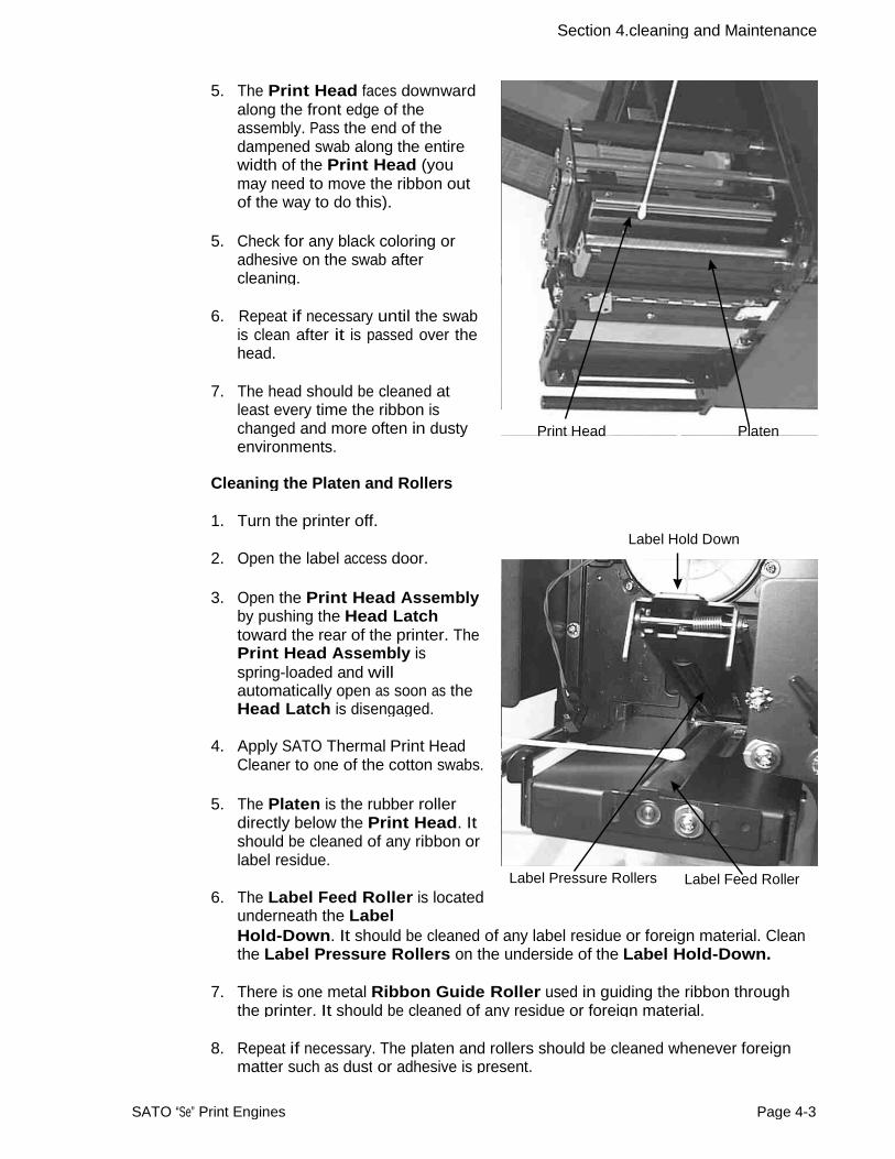
Section 4.cleaning and Maintenance
CLEANING THE SENSORS AND PAPER END SWITCH
There are two sensors that are used to control the positioning of the label. One is a transmissive see-thru sensor that detects the edge of the label by looking through the backing paper which is translucent and detecting the presence of the opaque label. The other is a reflective sensor that detects the light reflected from the bottom of the label liner. When a printed black Eye-Mark passes through the beam, the light is no longer reflected back to the sensor detector, indicating to the printer that it should use this position as the start of a new label. When dust, dirt, adhesive or other foreign matter interferes with the light path of either of these sensors, the results is erratic label positioning. These sensors should be cleaned regularly, at least every two rolls of labels. The Paper End Switch is located in front of the sensor window and should be periodically checked for residue on the actuator roller.
Supplies Needed: SATO SA070 Cleaning Kit
1. Turn the printer off.
2. Open the label access door. 3. Open the Label Hold-Down by
disengaging the latch. The Label Hold-Down is spring loaded and will stay in the up position. The Upper Sensor will be visible on the underside of the Label Hold-Down when it is raised. It is adjustable over a range of 0.5" (14 mm) to 2.67" (68mm ) from the inside edge of the label. The Sensor Window is positioned directly below the Upper Sensor.
Upper Sensor Ribbon Guide Roller
4. Apply SATO Thermal Print HeadCleaner to one of the cotton swabs.
5. Use the cotton swab to clean any foreign matter from the exposed surface of the sensors.
6. Check the roller on the Paper
End Switch for residue and clean if necessary.
Sensor Window Paper End Switch
Page 4-4 SATO “Se” Print Engines
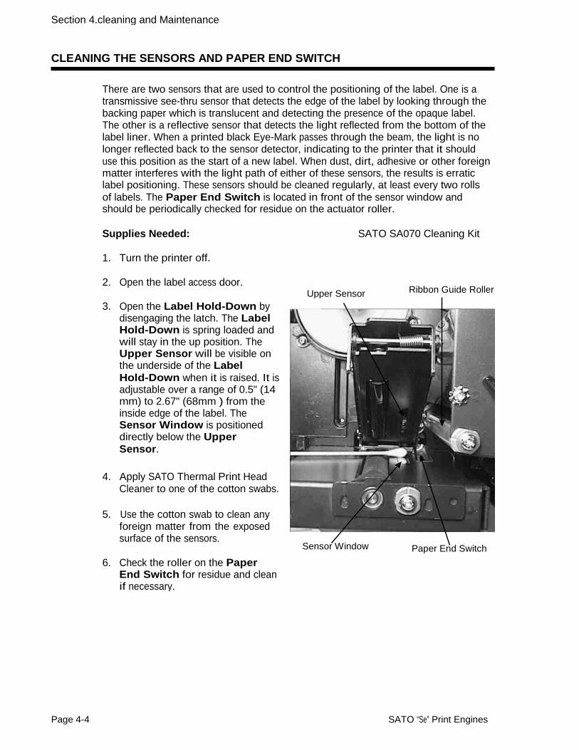
Section 4.cleaning and Maintenance
REPLACING THE PRINT HEAD
The print head is a user-replaceable item. If it becomes damaged for any reason, it can be easily removed and replaced. Contact your local SATO representative for information on obtaining a new print head.
Supplies needed: Flat Blade Screwdriver (Note: Some units may requirea No. 2 Phillips screwdriver)
1. Turn the printer off and remove the power cable.
2. Open the Label Access door.
3. View the Print Head Assembly from the front of the printer. Locate the center mounting screw on the top of the assembly. (Do not take out the two outside alinment screws!)It is accessible through the center hole in the Top Assembly Plate. Remove this screw and set it aside.
Screwdriver
4. Open the Print Head Assembly by pushing the Head Latch toward the rear of the printer. The Print Head Assembly is spring-loaded and will automatically open as soon as the Head Latch is disengaged.
Retaing ScrewAccess Hole
5. Remove the ribbon from theRewind Spindle if necessary.
6. The Print Head should now be loosened from the top of the assembly by grasping either side and carefully pulling it down and forward.
7. Disconnect the signal and power cables from the print head connectors and set the Print Head aside. Print Head Print Head Cables
8. Carefully attach the new print head to the connectors, using caution to make sure the connector keys are correctly positioned.
SATO “Se” Print Engines Page 4-5

Section 4.cleaning and Maintenance
NOTE: Be careful not to scratch the printing surface of the print head while installingit. Scratching the surface will cause permanent and irreparable damage and is not covered by the warranty!
9. Locate the mounting screw in the top plate assembly and align it with the tapped hole in the new print head.
10. Re-secure the print head by tightening the screw.
REPLACING THE FUSE
Supplies needed: 250V 15A Fuse
1. Turn the printer power off and remove the power cable.
2. On the back of the printer, locate the Fuse Cap directly above the AC connector.
3. Unscrew the cap and remove the defective fuse.
4. Replace with a new 250V 15A fuse.
5. Screw the fuse cap back onto the printer and replace the power cable.
AC Fuse
AC Input Connector
Page 4-6 SATO “Se” Print Engines
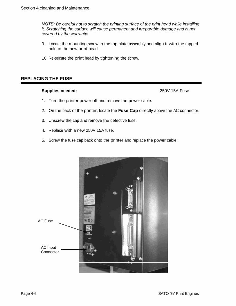
SECTION 5 PROGRAMMING REFERENCE
INTRODUCTION
This section presents a brief overview of the commands that are used with the SATO “Se” printers to produce labels with logos, bar codes and alphanumeric data.
The following information is presented in this section:
• The SATO Programming Language
• Selecting Protocol Control Codes
• Using Basic
• The Print Area
• Command Codes
THE SATO PROGRAMMING LANGUAGE
A programming language for a printer is a familiar concept to most programmers. It isa group of commands that are designed to use the internal intelligence of the printer.The commands, which are referred to as SATO Command Codes, contain non-printable ASCII characters (such as <STX>, <ETX>, <ESC>) and printable characters. These commands must be assembled into an organized block of code to be sent as one data stream to the printer, which in turn interprets the command codes and generates the desired label output. The programmer is free to use any programming language available to send the desired data to the printer.
The command codes used are based upon “Escape” (1B hexadecimal) sequences. Typically there are four types of command sequences:
<ESC>{Command}
These commands generally tell the printer to perform a specific action, like “clear the memory.”
<ESC>{Command} {Data}
Commands with this format tell the printer to perform a specific action which isdependent upon the following data, like “print X labels”, where the value for X iscontained in the data.
<ESC>{Command} {Parameter}
These commands set the operational parameters of the printer, like “set the print speed to 3.”
<ESC> {Command} {Parameter} {Data}
SATO “Se” Print Engines Page 5-1

Section 5. Programming Reference
Some commands can contain both Parameter and Data elements, such as “print a Code 39 symbol containing the data.”
SELECTING PROTOCOL CONTROL CODES
Protocol codes are the special control characters that prepare the printer to receive instructions. For example, the <ESC> character tells the printer that a command code will follow and the <ENQ> character asks for the printer status.
There are two different sets of Protocol Control codes to choose from on the printer. Each set is made up of six special characters. The Standard Protocol Control codes are non-printable characters, and the Non-Standard Protocol Control codes are printable characters. The Non-Standard set may be useful on host computers using protocol converters or in an application where non-printable ASCII characters cannot be sent from the host. This manual uses the Standard Protocol Control codes for all of the examples.
The Protocol Control codes are selected by a DIP switch DSW2-7 on the front panel. See Section 3: Printer Configuration.
CONTROL CHARACTER
STANDARD DSW2-7 OFF
NON-STANDARDDSW2-7 ON
DESCRIPTION
STX 02 Hex 7B Hex = { Start of Data
ETX 03 Hex 7D Hex = } End of Data
ESC 1B Hex 5E Hex = ^ Command code to follow
ENQ 05 Hex 40 Hex = @ Get printer status
CAN 18 Hex 21 Hex = ! Cancel print job Off-Line 40 Hex 5D Hex = ] Take printer Off-Line
USING BASIC
It may be useful to test your printer using a BASIC program on a PC. You may also write your actual production programs in BASIC. Whatever the reason, if you will be working in BASIC, some of the following hints may help you get started:
1. Set the WIDTH of the output device to 255 characters to avoid automatically sending <CR> and <LF> characters after every line. The command string should be continuous and uninterrupted by <CR> and/or <LF> commands. The examples given in this manual are printed on separate lines because they will not fit on one line and do not contain any <CR> and/or <LF> characters. If these characters are needed, they are explicitly noted by the inclusion of <CR> and <LF> notations.
2. If you are using the printer’s RS232C interface, it is necessary to set the COM port on the PC such that the CTS and DSR signals will be ignored. Send your OPEN “COM” statement in the following way:
Page 5-2 SATO “Se” Print Engines

Section 5. Programming Reference
OPEN “COM1:9600,E,8,1,CS,DS” AS #1
This sets the RS232C communication parameters of the host PC’s COM1 port for9600 baud, Even parity, 8 Data bits, 1 Stop bit and directing the port to ignore theCTS and DSR control signals.
3. You may want to minimize keystrokes and program size by assigning the <ESC>character to a string variable since this character is used quite often.
The following two examples in BASIC show a typical example using these hints. Both of these examples use the Standard Protocol codes.
Printing with the Parallel Port
5 REM Parallel Example Identifies the program as a parallel port print label. The “REM” prevents this data from being sent to the printer and displays it only on the screen.
10 E$=CHR$(27) Sets the “E$” string as an <ESC> character
20 WIDTH “LPT1:”,255 Sets the width of the output to 255 characters
30 LPRINT E$;"A"; Sends an “<ESC>A” command code to the LPT1 parallel port
40 LPRINT E$;"H400",E$;"V100";E$;"WL1SATO"; Sends the data “SATO” to be to be placed 400 dots horizontally and 100 dots vertically on the label and printed in the “WL” font.
50 LPRINT E$;"Q1"; Instructs the printer to print one label.
60 LPRINT E$; “Z”; Tells the printer that the last command has been sent. The printer can now create and print the job.
Printing with the RS232C Port
5 REM RS232 Example Identifies the program as a RS232C port print label. The “REM” prevents this data from being sent to the printer and displays it only on the screen.
10 E$=CHR$(27) Sets the “E$” string as an <ESC> character.
20 OPEN “COM1:9600,N,8,1,CS,DS” AS #1 Opens the COM1 port for output and sets the parameters as 9600 baud, No parity, 8 Data bits, 1 Stop bit and instructs the port to ignore the CTS and DSR control signals.
30 PRINT #1,CHR$ (2); Sends an <STX> (ASCII Code a decimal “2”) to the printer instructing it to prepare to receive a message.
50 PRINT #1,E$;"A"; Sends an “<ESC>A” command code to Print Port #1 opened by statement 20 above.
SATO “Se” Print Engines Page 5-3

Section 5. Programming Reference
60 PRINT #1, E$;"H400",E$;"V100";E$;"WL1SATO";Sends the data “SATO” to be to be placed400 dots horizontally and 100 dots vertically on the label and printed in the “WL” autosmoothed font.
70 PRINT #1, E$;"Q1"; Instructs the printer to print a quantity of one label.
80 PRINT #1, E$; “Z”; Tells the printer that the last command has been sent. The printer can now create and print the job.
90 PRINT #1,CHR$ (3); Sends an <ETX> (ASCII Code decimal “3”) to the printer telling it that this is the end of the message.
THE PRINT AREA
The maximum print area depends upon the printer model. The default for all printers is 7 inches long. If the pitch area is expanded with the <ESC>EX0 Expanded Print Length command, the maximum length can be extended to 49.2 inches for the all printers except the M-8490Se which is 32.8 inches. The length is limited by the available digits (9999) in the Vertical position commands. Many of your label applications will not require labels this large, therefore, it is important to understand how to work with labels that do not use the entire print area. The goal is to help you avoid printing where no label exists, which may lead to print head damage, not to mention the frustration when you cannot see the printed output.
The following diagram illustrates the print area for a standard (Right-Hand) M-8485Se and a sample 2 inch wide by 3 inch long label placed within this area. Ascan be seen, your label will be oriented against the inside right edge of the printer asviewed from the front (label exit) of the printer. If you are using an M-8485Se Left-Hand printer, the reference point is on the outside edge of the label away from the mounting plate. The normal reference point is located at the H1, V1 position of the print area in the normal print orientation (no rotation).
The base reference point is always on the right edge of the print head as you face the front (label exit) of the printer. If you are using a label that is narrower than the maximum print width, you may have to adjust the base reference point of the Left-Hand printer to correctly position the print area. If you are using a Left-Hand M-8485Se and need to adjust the position of the label there are three methods available to make sure your printed output will appear correctly on your label. They are as follows:
1. Media Size Command. Use the <ESC>A1 Media Size Command. This command specifies the width and length of the label. The printer will automatically calculate the correct offsets for printing labels of that size. However, if you specify a label size with this command, the labels loaded should match the size specified to correctly position the label.
2. Base Reference Point Command. Send the <ESC>A3 Base Reference Pointcommand as part of your data to the printer to set a new base reference point foryour label.
Page 5-4 SATO “Se” Print Engines

Section 5. Programming Reference
Normal Reference Point H1, V1
3" 3"
YourLabel
7" 2"
5"
M-8485S Print Area
Calculate the distance (in dots) that corresponds to the amount you wish to shift the label print area. If you wanted to move the print area over to the left (as viewed from the front or label exit end of the printer) 3.0 inches:
Shift Distance = 3.0" x 25.4 mm/in x 8 dpmm = 610 dots
New Base Reference Point = 610 dots
Issue the Base Reference Point command after the Start command in your data stream.
<ESC>A3H0610V0001
This resets the reference point for all the following data.
Note: After the reference point is moved, you can no longer print on the 610 dot“margin” unless the reference point is reset.
3. Adjust the <ESC>H Horizontal Position. Use the normal base reference point from the print area and use the horizontal position for each field to properly locate it on the label.
Calculate the distance (in dots) from the normal base reference point to the closest edge of the label.
Shift Distance = 3.0" x 25.4 mm/in x 8 dpmm = 610 dots
Each <ESC>H command would have the value “610” added to it to correctly position each field.
SATO “Se” Print Engines Page 5-5

Section 5. Programming Reference
Mounting Plate
Base ReferencePoint, H=0001
MountingPlate Base Reference
Point, H=0001
Label Label
5" 2"
Left-Hand Printer
The Command Code subsection contains a sample label output for each command code. These samples reflect how the printed information would appear on a five inch wide label (see illustration). If you want to test any of the sample label outputs and are using labels less than five inches in width, you will have to adjust the positioning accordingly so that the printer does not try to print where there is no label.
You must be careful not to print off the label surface as the label provides a heat sinkfor the print head elements. Doing so will cause irreparable damage to the head. Thisdamage is not covered under the print head warranty.
For example, the following illustrates a sample data stream and the resulting label assuming a five inch wide label on a left-hand model printer:
<ESC>A <ESC>H0050<ESC>V0100<ESC>L0303<ESC>MSATO<ESC>H0050<ESC>V0200<ESC>B103100*SATO* <ESC>Q1<ESC>Z
If you are using a two inch wide label, the entire image may not appear on your label. By adding the following Base Reference Point command to the second line of the data
H=50
V=100 SATOV=200
*SATO**SATO**SATO*
2" 5"
Unshifted Print Area
Page 5-6 SATO “Se” Print Engines
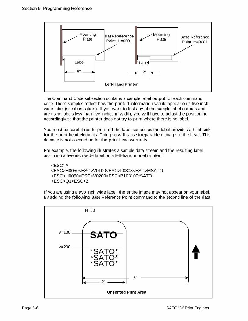
Section 5. Programming Reference
Left-Hand Printer
SATO
*SATO* *SATO* *SATO*
SATO *SATO* *SATO* *SATO*
2" Label
5"
Original image must be moved towardsthe inside of the printer to make it print
on a 2" wide label.
stream, the base reference point will be changed, causing the image to be shifted over toward the inside of the printer where it can be printed on the narrower label.
<ESC>A <ESC>A3H0610V0001 <ESC>H0050<ESC>V0100<ESC>L0303<ESC>MSATO <ESC>H0050<ESC>V0200<ESC>B103100*SATO* <ESC>Q1<ESC>Z
The image reference point is set at the right edge (edge closest to the printer side plate) of the label so that it can be printed on a 2 inch wide label.
Note: The printers will not “wrap” images that extend beyond the print area. If any part of a character or image extends beyond the print area, it will disappear.
For more information, see the Base Reference Point command description.
ROTATED FIELDS
The printers can rotate each print field in 90° increments using the Rotate command.
• <ESC>% - The field rotates, but the base reference point for the field remains the same.
The following data stream will rotate the print field but will not change the base reference point of the field:
<ESC>A<ESC>%1<ESC>V800<ESC>H200<ESC>L0202<ESC>WB1E<ESC>Q1<ESC>Z
SATO “Se” Print Engines Page 5-7
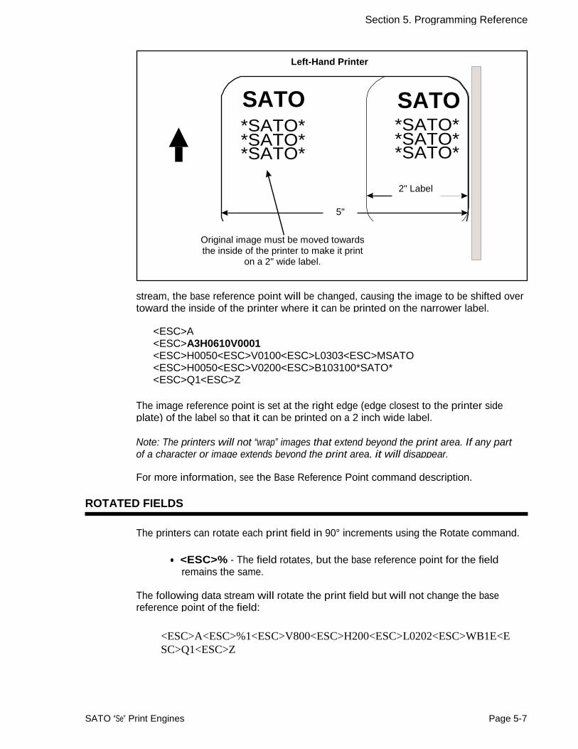
Section 5. Programming Reference
Original Base
Reference Point
H = 200
Label FeedDirection
V = 800
“%1”
COMMAND DEFAULT SETTINGS
There are some types of commands that must have a value specified before a label can be printed. If the data stream does not contain these commands, a “default” value isassumed. The commands and the corresponding default values are:
COMMAND DEFAULT NOTEPrint Rotation 0° (1) Vertical Reference Point 0 (1) Horizontal Reference Point 0 (1) Character Pitch 2 (1) Base Reference Point H=1, V=1 (2) Character Expansion 1 (1) Print Darkness 2 (1) Print Darkness (M-8459Se) 3 (1) Print Speed 6 ips (2) Print Speed (M-8459Se) 4 ips (2)
NOTES:
(1) The settings for these commands will revert to the default value when the printer receives an <ESC>Z or an <ESC>*.
(2) These values transmitted with these commands will remain in effect until a new command is received.
Page 5-8 SATO “Se” Print Engines
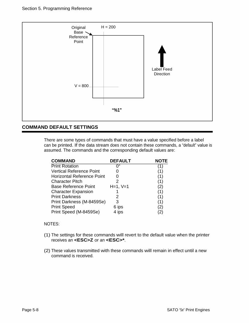
Section 5. Programming Reference
OPPOSITE HAND MODELS
The standard “Se” print engine is referred to as a “right-hand” printer (i.e., when facing the Control Panel, the label comes out from left to right). The M-8485Se, M-8460Se and M-8490Se are also available in a “left-hand” (i.e., the labels comes out right to left) version. The M-8459Se is only available in the standard Right-Hand configuation.
Mounting Plate
Label Label
Right Hand Printer H = 0001 Left Hand Printer
The only difference in the print area is the horizontal base reference point for the label. With the standard “Se” printer, the reference point is the first print position nearest the inside frame. With the “left-hand” version, the reference point is the first print position away from the frame. The same command stream sent to both printers should print anidentical label except the image may be shifted because of the relative positioning of the label under the print head.
SATO “Se” Print Engines Page 5-9

Section 5. Programming Reference
COMMAND CODE PAGE REFERENCE
It is beyond the scope of this basic Operator’s manual to cover all the SBPL commands here in detail. Refer to the E Series Programming Reference available from your authorized SATO dealer. To give you a basic overview, here is a summary of SBPL syntax and structure found in the Programmging Reference.
Each command begins on a separate page with its own heading. A uniform layout is used to help you find key information about each command. For each Command Code in this section, there will be a sample data input stream to the printer and the expected print output. By studying the examples, you can learn how to use the particular command within a whole block of printer code. Pay particular attention to the “Special Notes” with each command to learn other important information.
The subject commands are highlighted in bold letters in the Reference Sheets. There are two parts to most, but not all, commands. The first is the command character which immediately follows the <ESC> code. It is always an upper case alpha or a special character (such as an “&” or a “%”). It is never a lower case alpha character. If the command requires additional variable information, it is represented by a group of lower case alpha characters immediately following the command character. For example, if an aaaabb is listed following the basic command, the printer will look for six characters immediately following the command. The first four would represent the value of aaaa and the next two the value of bb.
The maximum number of characters defined in a parameter is represented by the number of characters shown in the command structure. For example, a command followed by an aaaa can have up to four characters. In general, commands with only one parameter following the command can be entered without the leading zeroes. In the above example, you could enter either “809” or “0809”. However, certain commands require the exact number of matching characters. A command with two parameters listed following the command code, such as aaaabbbb require the exact number of digits to be entered. If the value of aaaa is“800” and the value of bbbb is “300”, then the parameters must be entered as “08000300”. It is recommended that you make it a practice to always enter leading zeros to prevent any mistakes. The commands must be sent to the printer in an organized fashion in order for the label(s) to print.
NOTE: These examples assume the use of the Standard Protocol Command Codes, with a Right-Hand version of the M-8485Se printer with a parallel interface and a five inch wide label which is the maximum width that will fit in the printer. If the same command stream is sent to an M-8490Se (300dpi) , the image will be reduced by 33% in size.
Page 5-10 SATO “Se” Print Engines
SECTION 6 INTERFACE SPECIFICATIONS
INTRODUCTION
The “Se” printers utilize a Plug-In Interface Module for maximum printer configuration flexibility. This section presents the interface specifications for the “Se” Series printers. These specifications include detailed information on how to properly interface your printer with your host system.
The following information is presented in this section:
• Interface Types
• Using the Receive Buffer
• IEEE1284 Parallel Interface
• Universal Serial Bus (USB) Interface
• Local Area Network (LAN) Interface
• RS232C Serial Interface General Specifications Electrical Specifications Pin Assignments Ready/Busy Flow Control X-On/X-Off Flow Control Bi-Directional Communications Protocol
• Bi-Comm Communications Protocol
• Status Response
INTERFACE TYPES
The parallel interface for the “Se” printers is a high speed, bi-directional interface that conforms to the IEEE1284 specification (ECP mode on some computers). The interfaceis also compatible with the older Centronics parallel interface standard. If it does not detect the correct IEEE1284 signals in the interface connection, it will automatically operate in the standard Centronics mode which is much slower. To use the IEEE1284 parallel interface to its fullest capability requires that the host also have an IEEE1284 compatible interface and that the two be connected with a cable that meets the IEEE1284 specification. If either of these two are not present, the data rate is severely compromised.
In order to provide flexibility in communicating with a variety of host computer systems all “Se” printers use a Plug-In Interface Module. The IEEE1284 Interface module is shipped with the printer unless another interface type is specified at the time of the order. The other interfaces available are a high speed (to 57.6K bps) serial interface, an Ethernet interface or an optional Universal Serial Bus (USB) interface.
SATO “Se” Print Engines Page 6-1
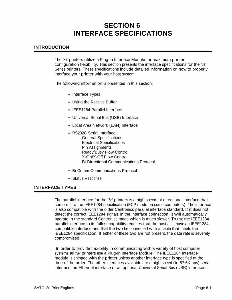
Section 6. Interface Specifications
The Parallel interface will probably be the most useful in communicating with IBM PCs and compatibles. The RS232C Serial interface allows connectivity to a number of other hosts. The USB interface allows the printer to be connected to a computer that supports peripherals attached to a USB bus. Up to 127 peripherals can be connected to a single USB port.
WARNING: Never connect or disconnect interface cables (or use a switch box) withpower applied to either the host or the printer. This may cause damage to the interface circuitry in the printer/host and is not covered by warranty.
THE RECEIVE BUFFER
The “Se” printers have the ability to receive a data stream from the host in one of two ways. The receive buffer may be configured to accept one print job at a time or multiple print jobs. The single job print buffer is generally used by software programs that wish to maintain control of the job print queue so that it can move a high priority job in front of ones of lesser importance. The multiple job buffer, on the other hand prints all jobs in the order they are received by the printer, and the order of printing cannot be changed.
Single Job Buffer
The printer receives and prints one job at a time. Each job must not exceed 2.95 MB.
Multi Job Buffer
The printer is able to continuously receive print jobs, compiling and printing other jobs at the same time. It acts much like a “print buffer” to maximize the performance of the host and the printer.
When using the RS232C Serial interface, the Multi Job Buffer uses either the Ready/Busy with DTR (pin 20) or X-On/X-Off flow control protocols. See these sections for more details. With an empty receiving buffer, the status of DTR is “high” (or an X-On status if using X-On/X-Off), meaning the printer is ready to receive data. When the receive buffer is holding 2.0 MB of data (1 MB from being full), DTR
Page 6-2 SATO “Se” Print Engines

Section 6. Interface Specifications
will go “low” (or an X-Off is sent) indicating the printer can no longer receive data. This condition is called “Buffer Near Full.”
0 B 2.0 MB 2.95 MB
DTR High or
X-On DTR Low
Buffer Near Full X-Off
The receiving buffer will not be able to receive more data again until a “Buffer Available” condition occurs. This takes place when the receiving buffer has emptied so that only 1 MB bytes of data are being held (2.0 MB bytes from being full). At this time, DTR will go “high” or an X-On is sent to tell the host that it can again receive data.
0 B 1 MB 2.95 MB
DTR Low or
X-Off Buffer Available
DTR High or
X-On
All printer error conditions (i.e., label out, ribbon out) will cause the printer to go busy (DTR “low” or X-Off) until the problem is corrected and the printer is placed on-line. The printer will also be busy if taken off-line from the front panel.
IEEE1284 PARALLEL INTERFACE
The parallel interface for the “Se” printers is a Plug-In Interface Module that can be installed by the user. It conforms to the IEEE1284 specification. It will automatically detect the IEEE1284 signals and operate in the high speed mode. If it does not detect the IEEE1284 signals, it will operate in the standard Centronics mode, which is significantly slower. For this reason, an interface cable and host interface conforming to the IEEE1284 specification must be present to fully utilize the speed capabilities. This interface also operates bi-directionally and can report the status of the printer back to the host.
ELECTRICAL SPECIFICATIONS
Printer Connector AMP 57-40360 (DDK) or equivalent
Cable Connector AMP 57-30360 (DDK) or equivalent
SATO “Se” Print Engines Page 6-3
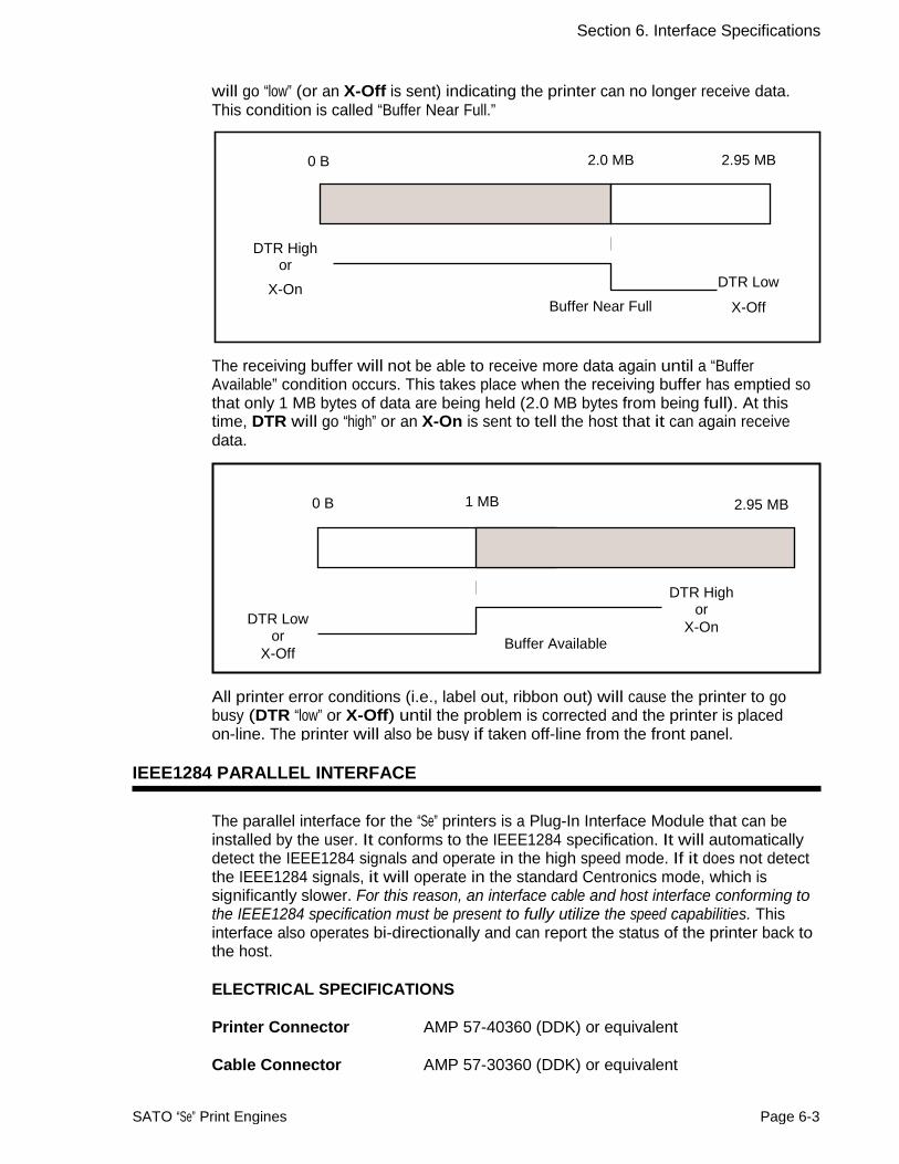
Section 6. Interface Specifications
Cable IEEE1284 Parallel, 10 ft. (3 m) or less
Signal Level High = +2.4V to +5.0VLow = 0V to -0.4V
DATA STREAMS
<ESC>A . . Job#1 . . <ESC>Z<ESC>A . . Job#n . . <ESC>Z
IEEE1284 Parallel Interface Pin Assignments
PIN SIGNAL DIRECTION PIN SIGNAL DIRECTION
1 STROBE To Printer 19 STROBE Re- turn
Reference
2 DATA 1 To Printer 20 DATA 1 Return Reference 3 DATA 2 To Printer 21 DATA 2 Return Reference
4 DATA 3 To Printer 22 DATA 3 Return Reference
5 DATA 4 To Printer 23 DATA 4 Return Reference
6 DATA 5 To Printer 24 DATA 5 Return Reference
7 DATA 6 To Printer 25 DATA 6 Return Reference
8 DATA 7 To Printer 26 DATA 7 Return Reference
9 DATA 8 To Printer 27 DATA 8 Return Reference
10 ACK To Host 28 ACK Return Reference 11 BUSY To Host 29 BUSY Return Reference 12 PTR ERROR To Host 30 PE Return Reference 13 SELECT To Host 31 INIT From Host
14 AUTOFD (1) To Host 32 FAULT To Host 15 Not Used 33 Not Used 16 Logic Gnd 34 Not Used 17 FG Frame Ground 35 Not Used 18 +5V (Z=24K ohm) To Host 36 SELECTIN (1) From Host
(1) Signals required for IEEE1284 mode.
Page 6-4 SATO “Se” Print Engines

Section 6. Interface Specifications
RS232C SERIAL INTERFACE
The High Speed Serial Interface is a Plug-In Interface Module that can be installed in the printer by the user.
GENERAL SPECIFICATIONS
Asynchronous ASCII Half-duplex communication
Ready/Busy Hardware Flow Control Pin 20, DTR Control Pin 4, RTS Error Condition
X-On/X-Off Software Flow Control
Bi-Directional Communication
Data Rate 9600, 19200, 38400, 57600 bps
Character Format 1 Start Bit (fixed)7 or 8 data bits (selectable) Odd, Even or No Parity (selectable) 1 or 2 Stop bits (selectable)
ELECTRICAL SPECIFICATIONS
Connector DB-25S (Female)
Cable DB-25P (Male), 50 ft. maximum length. For cable configuration, refer to Cable Requirements appropriateto the RS232C protocol chosen.
Signal Levels High = +5V to +12VLow = -5V to -12V
Pin Assignments
Pin 13 Pin 1
Pin 25 Pin 14
SATO “Se” Print Engines Page 6-5

Section 6. Interface Specifications
RS232C Interface Signals PIN DIRECTION SIGNAL DEFINITION
1 Reference FG (Frame Ground)
2 To Host TD (Transmit Data) - Data from the printer to the host computer. Sends X-On/X-Off characters or status data (Bi-Directional protocols).
3 To Printer RD (Receive Data) - Data to the printer from the host computer.
4 To Host RTS (Request to Send) - Used with Ready/Busy flow control to indicate an error condition. RTS is high and remains high unless the print head is open (in this case, RTS would return to the high state after the print head is closed and the printer is placed back on-line) or an error condition occurs during printing (e.g., ribbon out, label out).
5 To Printer CTS (Clear to Send) - When this line is high, the printer assumes that data is ready to be transmitted. The printer will not receive data when this line is low. If this line is not being used, it should be tied high (to pin 4).
6 To Printer DSR (Data Set Ready) - When this line is high, the printer will be ready to receive data. This line must be high before data is transmitted. If this line is not being used, it should be tied high (to pin 20).
7 Reference SG (Signal Ground)
20 To Host DTR (Data Terminal Ready) - This signal applies to Ready/Busy flow control. The printer is ready to receive data when this pin is high. It goes low when the printer is off-line, either manually or due to an error condition, and while printing in the Single Job Buffer mode. It will also go low when the data in the buffer reaches the Buffer Near Full level.
Cable Requirements
DB9 DB25 HOST INTERCONNECTION PRINTER
1 1 FG ←⎯⎯⎯⎯→ 1 FG (Frame Ground)
2 3 RD ←⎯⎯⎯⎯⎯ 2. TD (Transmit Data)
3 2 TD ⎯⎯⎯⎯⎯→ 3 RD (Receive Data)
8 5 CTS ←⎯⎯⎯⎯⎯ 4 RTS (Request to Send)
7 4 RTS ⎯⎯⎯⎯⎯→ 5 CTS (Clear to Send)
4 20 DTR ⎯⎯⎯⎯⎯→ 6 DSR (Data Set Ready)
6 6 DSR* ←⎯⎯⎯⎯⎯ 20 DTR (Data Terminal Ready)
5 7 SG ←⎯⎯⎯⎯→ 7 SG (Signal Ground) *This connection at the host side of the interface would depend upon the pin that is being used as the Ready/Busy signal by the driving software.Typically,on a PC, it would be either CTS(pin5) or DSR(pin6) on a DB-25 connector.
READY/BUSY FLOW CONTROL
Ready/Busy is the hardware flow control method for the serial interface on the Se printers. By raising/lowering the voltage level on Pin 20 of the RS232C port, the printer notifies the host when it is ready to receive data. Pin 4 (RTS) and pin 20
Page 6-6 SATO “Se” Print Engines
Section 6. Interface Specifications
(DTR) are the important signals on the printer for this method of flow control. The host must be capable of supporting this flow control method for it to function properly.
X-On/X-Off FLOW CONTROL
X-On/X-Off flow control is used whenever hardware (Ready/Busy) flow control is not available or desirable. Instead of a voltage going high/low at pin 20, control characters representing “Printer Ready” (X-On =11 hexadecimal) or “Printer Busy” (X-Off = 13 hexadecimal) are transmitted by the printer on pin 2 (Transmit Data) to the host. In order for this method of flow control to function correctly, the host must be capable of supporting it. X-On/X-Off operates in a manner similar to the function of pin 20 (DTR) as previously explained. When the printer is first powered on it sends an X-Off when the “Buffer Near Full” level is reached and a X-On when the data level of the buffer drops below the “Buffer Available” mark. When the printer is taken off-line manually, it transmits an X-Off indicating it cannot accept data. When it is placed back on line manually, it sends an X-On, indicating it is again available for receipt of data. If an error occurs during printing (paper out, ribbon out), the printer sends an X-Off as soon as an error condition is detected. When the error is cleared and the printer is placed back on-line, it transmits an X-On indicating it is again ready to accept data.
Upon power up if no error conditions are present, the printer will continually sendX-On characters at five millisecond intervals until it receives a transmission from the host.
Data Streams
The data streams for X-On/X-Off and Ready/Busy flow control are constructed in the same way as they are for Ready/Busy flow control.
<ESC>A . . Job#1 . . <ESC>Z<ESC>A . . Job#n . . <ESC>Z
Example: <ESC>A . . Job#1 . . <ESC>Z
NOTE: All charactersare in ASCII.
UNIVERSAL SERIAL BUS (USB) INTERFACE
The Universal Serial Bus (USB) interface is a Plug-In Interface Module that can be installed by the user. It requires a driver (shipped with each printer that has the interface installed) that must be loaded on your PC and the PC must be configured to support USB peripherals using Windows 98. Details for loading the USB driver are contained in the USB Interface Manual that is shipped with each printer with a USB Optional interface installed. Up to 127 devices may be connected to a USB port.
SATO “Se” Print Engines Page 6-7

Section 6. Interface Specifications
LOCAL AREA NETWORK (LAN) OPTIONAL INTERFACE
A Local Area Network (LAN) interface is a Plug-In Interface Module that can be installed by the user. It requires a driver shipped with each printer that has the interface installed. The driver that must be loaded on your PC and the PC must be configured to support the TCP/IP network protocol using a 10/100BaseT LAN connection. Details for loading the LAN driver are contained in the LAN Interface Manual that is shipped with each printer with a LAN Optional interface installed.
BI-DIRECTIONAL COMMUNICATIONS
This is a two-way communications protocol between the host computer and the printer, thus enabling the host to check printer status. When Bi-Com 4 communications is selected, there is no busy signal from the printer. The host must request the complete status from the printer, including ready/busy. The host may request status in two different ways.
ENQUIRE/ACK/NAK
In the Bi-Com 4 mode, the host transmits an ENQ (05 hexadecimal) to the printer and the printer will respond with its status within five milliseconds. If printing, it will respond upon finishing the current label, then resume printing. In order for this protocol to work properly with an RS232C Interface, pin 6 (DTR) and pin 5 (CTS) must be held high by the host. One way to ensure these pins are always in the correct state is to tie pin 20 (DTR) to pin 6 (DSR) and pin 4 (RTS) to pin 5 (CTS) at the printer end of the cable.
Enquire (ENQ)
Upon receipt of an ENQ command, the printer responds with 25 bytes of status information bounded by an STX/ETX pair. The Bi-Com protocol works only in the Multi Job Buffer mode. The status information is defined as follows:
<STX>{ 2 Byte ID}{1 Status Byte}{6 Byte Label Remaining}{16 Byte Job Name}<ETX>
• ID - This is a two byte number identifying the current print job ID. The print job ID is defined using the <ESC>ID Job ID command transmitted with the print job (see Job ID Store in the command listing for more information on how to use this command). The range is from 00 to 99.
• Status - A single byte defining the current status of the printer (see the Status Byte Definition table).
• Label Remaining - Six bytes defining the number of labels remaining in
the current print job. The range is from 000000 to 999999 labels.
• Job Name - 16 bytes of ASCII characters identifying the name assigned tothe job by the <ESC>WK Job Name command. If the Job Name is less than
16 characters, the field will be padded with leading zeroes.
If an ENQ is received after the print job specified in the ID bytes has been completed, or there is no data in the buffer, the printer will respond with two “space” characters
Page 6-8 SATO “Se” Print Engines
Section 6. Interface Specifications
(20 hexadecimal) for the ID number, six “zero” characters (30 hexadecimal) in theRemaining Labels bytes and the 16 byte Job Name.
Cancel (CAN)
If a CAN (18 hexadecimal) command is received , it will stop the print job and clear all data from the receive and print buffers. A delay of five milliseconds or more is required before any new data can be downloaded. The CAN command is effective immediately upon receipt, even if the printer is off-line or in an error condition. The printer will return an ACK (06 hexadecimal) if there is no printer error condition and a NAK (15 hexadecimal) if an error condition exists.
Print Job
Upon receipt of a valid print job (<ESC>A . . . <ESC>Z), an ACK (06 hexadecimal) will be returned by the printer if there are no errors and a NAK (16 hexadecimal) if a printer error exists (this protocol only works with the RS232C interface).
Print Stop (DLE)
If a DLE (10 hexadecimal) is received by the printer, the print process is stopped and an ACK (06 hexadecimal) is returned if there are no errors and a NAK (16 hexadecimal) if a printer error exists.
Print Start (DC1)
If the printer has been stopped by receipt of a DLE (10 hexadecimal) command, it can be restarted by sending a DC1 (hexadecimal 11) command. Upon receipt of this command an ACK (06 hexadecimal) is returned if there are no errors and a NAK (16 hexadecimal) if a printer error exists.
(1) To provide compatibility with older SATO printers, the RS232C interface can be configured to use an earlier Bi-Com 3 ENQ/ACK/NAK protocol selected via DSW2-8 and DSW1-7/8 (on the RS232C Interface module). The earlier protocol did not have provisions for the Job Name and did not respond to the DLE or DCI commands. Also, there are additional Response Codes in the Status Byte Definition. It is recommended that you use the current protocol rather than the earlier version unless it is necessary for compatibility with existing software.
SATO “Se” Print Engines Page 6-9

Section 6. Interface Specifications
Status Byte Definition, Bi-Com Protocol
ASCII HEX DEFINITION OFF-LINE
0 30 No Errors
1 31 Ribbon Near End
2 32 Buffer Near Full
3 33 Ribbon Near End and Buffer Near Full
4 (1) 34 Print Stop (no error)
ON-LINE, WAITING FOR DATA
A 41 No Errors
B 42 Ribbon Near End
C 43 Buffer Near Full
D 44 Ribbon Near End and Buffer Near Full
E(1) 45 Print Stop (without error)
ON-LINE, PRINTING
G 47 No Errors
H 48 Ribbon Near End
I 49 Buffer Near Full
J 4A Ribbon Near End and Buffer Near Full
K 1 4B Print Stop (without error)
ON-LINE, WAITING TO DISPENSE A LABEL
M 4D No Errors
N 4E Ribbon Near End
O 4F Buffer Near Full
P 50 Ribbon Near End and Buffer Near Full
Q 1 51 Print Stop (without error)
ON-LINE, COMPILING PRINT JOB
S 53 No Errors
T 54 Ribbon Near End
U 55 Buffer Near Full
V 1 56 Ribbon Near End and Buffer Near Full
W(1 1 56 Print Stop (without error)
OFF-LINE, ERROR CONDITION
b 62 Head Open c 63 Paper End d 64 Ribbon End e 65 Media Error f 66 Sensor Error
g 67 Head Error j 6A Cutter Error
k 6B Other Error Condition 1 Not supported by legacy Bi-Comprotocols
Page 6-10 SATO “Se” Print Engines

Section 6. Interface Specifications
STATUS RESPONSE
The second method of determining printer status is to interrograte the printer with specific commands. The response from these commands will provide specific information about the printer status depending upon the command. This allows the controlling application to determine the status of a printer when it is located in a remote location.
Printer Status (SOH + MG)
Upon Receipt of an SOH (hexadecimal 01) followed immediately by an ASCII MGcauses the printer to return a 30 byte Printer Status Word bounded by an STX-ETXpair that reports the current operating status of the printer.
BYTE NUMBER
HEX VALUE
DESCRIPTION
1 00 Thermal Transfer Print Type01 Direct Thermal Print Type
2 00 203 dpi Resolution01 305 dpi Resoution
3 00 2 ips Print Speed01 02 03 04 05 06 07 08 09
3 ips Print Speed4 ips Print Speed 5 ips Print Speed 6 ips Print Speed 7 ips Print Speed 8 ips Print Speed 9 ips Print Speed 10 ips Print Speed12 ips Print Speed
4 00 Not Supported01 02 03 04
Not SupportedNot Supported Label Dispense Print modeReserved
5 00 Not Supported01 02
Not SupportedNot Supported
6 00 Dispense at head position01 Dispense at dispense position
7 00 Reserved 8 41 Not Supported
42 43
Not SupportedNot Supported C
SATO “Se” Print Engines Page 6-11

Section 6. Interface Specifications
BYTE NUMBER
HEX VALUE
DESCRIPTION
9 00 Print Density Level 101 02 03 04
10 00
01 02
11 00
01
Print Density Level 2Print Density Level 3 Print Density Level 4 Print Density Level 5 Reflective (Eye-Mark) SensorGap (See-Thru) Sensor No Sensor Zero Slash Disabled Zero Slash Enabled
12 00 Reserved
13 00 01
14 00
01
15 00 01
16-17 00 to C80
00 to 12C0 18-19 00 to 340
00 to 4E0 20-21 00 to 3E7
FFFF to FC19 22-23 00 to 320
00 to FCE0
24 00 to 63 FF to 9D
25 00 to 63
FF to 9D
26 00 to 63 FF to 9D
27 00 to 63
FF to 9D
28 00 01
Not SupportedNot Supported Online Feed Disabled Online Feed Enabled Fixed Pitch Proportional Pitch Not Supported Not Supported Vertical Base Reference Point Offset in dots (0 to 792) Vertical Base Reference Point Offset in dots (-1 to -792)
Horizontal Base Reference Point Offset in dots (0 to 800) Horizontal Base Reference Point Offset in dots (-1 to -800) Not Supported Not Supported Not Supported Dispense Offset in dots (0 to 99) Dispense Offset in dots (-1 to -99) Compatibility Mode Enabled Compatibility Mode Disabled
29 08 to 40 Not Supported
30 00 01
Buzzer EnabledBuzzer Disabled
Page 6-12 SATO “Se” Print Engines

Section 6. Interface Specifications
Counter Status (SOH + ME)
Upon Receipt of an SOH (hexadecimal 01) followed immediately by an ASCII ME causes the printer to return a 28 byte Head Counter Status Word bounded by an STX-ETX pair that reports the current status of the printer life counters.
BYTE NUMBER
VALUE DESCRIPTION
1-8 Hex Current Life Counter in dots 9-12 Hex 1st (Current) Head Counter in dots
13-16 Hex 2nd (Previous) Head Counter in dots 17-20 Hex 3rd Head Counter in dots 21-24 Hex Not Supported 25-28 Hex Not Supported
Sensor Status (SOH + SG)
Upon Receipt of an SOH (hexadecimal 01) followed immediately by an ASCII SGcauses the printer to return a 4 byte Sensor Status Word bounded by an STX-ETXpair that reports the values of the printer counters.
BYTE NUMBER
VALUE DESCRIPTION
1 Hex Reflective Sensor Level 2 Hex Transmissive Sensor Level
3 00H 01H
4 00H 01H
Out of PaperPaper Present Head Open Head Closed
SATO “Se” Print Engines Page 6-13

Section 6. Interface Specifications
Head Status (SOH + HC)
Upon Receipt of an SOH (hexadecimal 01) followed immediately by an ASCII HC causes the printer to return a 1 byte Head Fault Status Word bounded by an STX-ETX pair that reports the current operating status of the print head. Before the printer will respond to this command, it must be in the Head Check Mode (DSW2-3 = On).
BYTE NUMBER
HEX VALUE
DESCRIPTION
1 00 Print Head OK01 Electrical Fault in Print Head
System Version Information (SOH + SB)
Upon Receipt of an SOH (hexadecimal 01) followed immediately by a ASCII SB causes the printer to return a 50 byte Printer Status Word bounded by an STX-ETX pair that reports the system version of the printer.
BYTE NUMBER
VALUE DESCRIPTION
1-50 ASCII Firmware Version Information
Memory Status (SOH + EB)
Upon Receipt of an SOH (hexadecimal 01) followed immediately by an ASCII EB causes the printer to return a 24 byte Memory Status Word bounded by an STX-ETX pair that reports the current user memory allocation.
BYTE NUMBER
VALUE DESCRIPTION
1-4 Hex Free Font Memory 5-8 Hex Total Font Memory
9-12 Hex Free Form Overlay Memory
13-16 Hex Total Form Overlay Memory 17-20 Hex Free Graphic Memory 21-24 Hex Total Graphic Memory
Page 6-14 SATO “Se” Print Engines

Section 6. Interface Specifications
Form Overlay Status (SOH + FO)
Upon Receipt of an SOH (hexadecimal 01) followed immediately by an ASCII FO causes the printer to return a 18 byte Form Overlay Status Word bounded by an STX-ETX pair that reports the Forms downloaded into the printer.
BYTE NUMBER
VALUE DESCRIPTION
1-2 01 to 99 Form Registration Number (ASCII value) 3-18 ASCII Form Name
SATO “Se” Print Engines Page 6-15

Section 6. Interface Specifications
Font Configuration (SOH + FG)
Upon Receipt of an SOH (hexadecimal 01) followed immediately by an ASCII FG causes the printer to return a 102 byte Font/Graphics Status Word bounded by an STX-ETX pair that reports information on the stored font or graphic.
Note: The printer must be in the Font/Graphic Download (See Section 3: Configuration) mode before a response will be received.
BYTE NUMBER
VALUE DESCRIPTION
1-2 ASCII Font ID Number
3-4 00H 01H
FontGraphic
5-36 ASCII Font Name 37-48 ASCII Font Style
49-52 ASCII Font Point Size
53-54 Hex Character Width in dots
54-60 Hex Character Height in dots
57-60 Hex Font Size
58-64 Hex Font Registration Number
65-68 Hex Font Data Top Address
69-72 Hex Total Size
73-74 Hex Vertical/Horizontal Writing Flag
75 Hex Character Pitch, Fixed/Variable
76 Hex Family Attribute
77 Hex Character Set
78 Hex Italic Attribute
79-80 Hex Weight Attribute
81-82 Hex Spread
83-84 Hex Assent in dots
85-86 Hex Registration Start Code
86-87 Hex Registration End Code
88-95 Hex Reserved
96-98 Hex Code
99-100 Hex Horizontal Valid Size
101-102 Hex Left Gap Size
Page 6-16 SATO “Se” Print Engines

Section 6. Interface Specifications
Interface Status (SOH + IG)
Upon Receipt of an SOH (hexadecimal 01) followed immediately by an ASCII IG causes the printer to return a 1 byte Interface Status Word bounded by an STX-ETX pair that reports the type of interface connection currently set in the printer.
BYTE NUMBER
VALUE DESCRIPTION
1 0 IEEE 1284 Parallel1 2 3
Serial RS232Local Area NetworkUniversal Serial Bus
Serial Interface Settings (SOH + H2)
Upon Receipt of an SOH (hexadecimal 01) followed immediately by an ASCII H2 causes the printer to return a 5 byte Serial IF Status Word bounded by an STX-ETX pair that reports the current operating parameters of the Serial RS232 Interface.
BYTE NUMBER
VALUE DESCRIPTION
1 0 9600 BPS1 2 3
19200 BPS38400 BPS57600 BPS
2 0 No Parity1 3
Odd ParityEven Parity
3 0 1 Stop Bit1 2 Stop Bits
4 0 Single Item Buffer with Ready/Busy Flow Control 1 2 3 4
Multi-Item Buffer with Ready/Busy Flow Control X-ON/X-OFF Flow Control Status 4 Bi-Comm Status 3 Bi-Comm
SATO “Se” Print Engines Page 6-17

Section 6. Interface Specifications
EXT CONNECTOR
The EXT connector on the rear panel of the “Se” printers is intended for use with the external printer accessories such as label rewinders or applicators. The 14-pin Centronics type connector provides a choice of four different output signals along with various error conditions. A DB-9 to 14-pin Centronics adapter cable is provided for legacy applications.
Pin Assignments
PIN DIRECTION SIGNAL DESCRIPTION 13 To Host Vcc - +5V
10 To Host Ribbon Near End - This pin goes high when the amount of ribbon on the unwind shaft is approximately 46 feet (14 m). The output will be low when the ribon is completely out.
4 To Host Error - This pin goes low when the printer detects an error condition such as head open or receiving buffer full.
7 To Printer Reprint - A duplicate of the last label in a print job will be reprinted when this signal is received.
5 To Printer Print Start - The printer will print one label when this pin is pulled to ground. This signal must be enabled by placing switch DSW3-5 on the Control Panel in the OFF position.
6 To Host End Print - It is used to drive an applicator or other external device requiring synchronization with the print cycle. You may choose between four types of output signals using control panel DSW3-6 and DSW3-7 selections.See timing charts on next page.
1 To Host Label Out - This pin goes low (0V) when a label out error exists.
3 To Host Ribbon Out - This pin goes low (0V) when the ribbon is out.
2 Reference Signal Ground
8 To Printer Reserved
9 To Host Off Line - This pin goes low (0V) when the printer if Off Line. Note: This conditions that determine when this line goes true can be modified by the LCD Service Mode Panel setting
11 Reserved
12 To Host +24V +/- 10% @2A - Power for external devices.
14 Frame Ground
NOTE: Thesignals on pins1,3,4,6,9 and10 each have an open collector output. These pins normally measure +.07V maximum when a true condition exists.If a false condition occurs, the voltage will drop to 0V. To achieve a signal level of +5V, you must add a 330ohm,1/4Wpull-up resistor between the open collector output pin and Vcc(pin 13) as illustrated. This will provide a signal level of +5V for a true condition and 0V when a false condition exists.The maximum voltage that can be applied to these pins is +50V and the maximum current they can sink is 500milliamps.
Page 6-18 SATO “Se” Print Engines

Section 6. Interface Specifications
Vcc= +5V Pin 13
330 ohm, 1/4W
Pin 1, 3, 4, 6, 9 or 10
Signal Out
STANDARD OPERATION Start of Print Cycle End of Print Cycle
Print StartInput
+5V 0V
Print RepeatInput
Print End Type 1
+5V 0V
+5V 0V
Print EndType 2
+5V 0V
20 milliseconds
Print EndType 3
+5V 0V
Print EndType 4
+5V 0V
SATO “Se” Print Engines Page 6-19

Section 6. Interface Specifications
REPEAT PRINT Start of Print Cycle End of Print Cycle
Print StartInput
+5V 0V
Print RepeatInput
Print End Type 1
+5V 0V
+5V 0V
Print EndType 2
+5V 0V
20 milliseconds
Print EndType 3
+5V 0V
Print EndType 4
+5V 0V
ERROR SIGNALS
Print Motion
Paper End
Moving Stopped
+5V
Paper or Ribbon End
Head Open
Paper/Ribbon Replinished
Head Closed
Ribbon End
Machine Error
Print End
Type 1
0V +5V 0V
+5V 0V
+5V 0V
Print EndType 2
+5V 0V
Print EndType 3
+5V 0V
Print EndType 4
+5V 0V
Page 6-20 SATO “Se” Print Engines

SECTION 7 TROUBLESHOOTING
This section has been devised to help you if you are unable to produce output on the“Se” Series printers. Use this section to make sure the basics have been checked before deciding you are unable to proceed any further. The section is divided into five parts:
• Initial Checklist
• IEEE1284 Parallel Interface
• RS232C Serial Interface
• Universal Serial Bus Interface
• LAN Ethernet Interface
INITIAL CHECKLIST
1. Is the printer powered up and ON-LINE?
2. Is the ERROR light on the front panel off? Is this light is on, it may mean the Print Head Assembly or the Label Hold-Down is not closed and latched in position.
3. Are the LABEL and RIBBON lights on the front panel off? If these lights are on, the labels or ribbons may be incorrectly loaded.
USING THE IEEE1284 PARALLEL INTERFACE
1. Is the IEEE1284 printer cable connected securely to your parallel port(DB-25S Female) on the PC and to the Parallel Interface connector on the printer?
WARNING: Never connect or disconnect interface cables (or use a switch box) with power applied to either the printer or the host. This may cause damage to the interface circuitry and is not covered by warranty.
2. Does the Parallel interface cable used meet IEEE1284 specifications? If itdoes not and you are connected to an IEEE1284 or ECP parallel port onthe computer, the printer may not be able to communicate correctly.
3. Is there more than one parallel interface port on your PC (LPT1, LPT2, etc.)? If so, make sure you are sending data out the correct port.
4. Is the IEEE1284 Interface Module installed in the printer? Older versions of the Parallel Interface module will not work correctly in the “Se” printers.
SATO “Se” Print Engines Page 7-1
Section 7. Troubleshooting
5. When you send the print job to the printer, and it does not respond, do you get an error message on your PC that says “Device Fault” or something similar?
This may mean that the computer doesn’t know the printer is there. Verify that:
a. Both ends of the cable are securely inserted into their respective connectors.
b. The printer is ONLINE.
c. The cable is not defective. There are other things that can cause this error message on your computer, but at this stage, a defective cable may be one of the reasons.
6. When you send the print job to the printer and it does not respond, and there is no error message on the PC:
a. Check your data stream for some of the basics. Is your job framed as follows?
<ESC>A—DATA—
b. Verify that you’ve included all required parameters in the data stream.
c. Verify the following:
• You have not typed a “0” (zero) for an “O” (letter) or vice-versa.
• You have not missed any <ESC> characters where they’re needed.
• Make sure all printer command codes are capital letters.
7. If you’ve checked all of the above and the printer still isn’t printing, you maywant to try a Buffer Hex Dump to determine what (if anything) the printer is receiving from your computer. See Printing Hex Dump Labels in Section 3: Configuration.
The Parallel port is now listening for incoming data. Send your print job. The printer will now print (only once) a Hexadecimal (Hex) Dump of everything it received from the host computer. Each 2-digit hexadecimal character represents a character the printer received. It may be tedious, but now you can analyze and troubleshoot the data stream.
7. While checking the Hex Dump printout, if you notice 0DH 0AH (Carriage Return and Line Feed) characters throughout. The command string should be continuous and no CR or LF characters are allowed between the Start Command (<ESC>A) and the Stop Command (<ESC>Z). If you are using BASIC, it may be adding these characters automatically as the line wraps. Adding a “width” statement to your program can help to suppress these extra 0DH 0AH characters by expanding the line length up to 255
Page 7-2 SATO “Se” Print Engines
Section 7. Troubleshooting
characters. See the beginning of Section 5: Programming Reference for details on writing a program in BASIC.
If you’re not programming in BASIC, check to see if you have an equivalent statement in the language you’re using to suppress extra carriage returns and line feeds from your data being sent out to the printer. We want the data stream to be one complete line going to the printer.
USING THE RS232C SERIAL INTERFACE
1. Is the RS232C Serial cable connected securely to your serial port on the PC(DB- 25S or DB-9S Male) and to the RS232C connector on the printer?
WARNING: Never connect or disconnect interface cables (or use a switch box) with power applied to either the printer or the host. This may cause damage to the interface circuitry and is not covered by warranty.
2. Is the cable defective? At the very least, you should be using a “Null Modem Cable,” which crosses pins in a specific manner. This should enableyour printer to print. But we recommend that you eventually use a cable built to specifications as described in Section 6: Interface Specifications.
3. Is the RS232 Interface Module installed in the printer? The “Se” printers require the new Hi Speed Serial Interface (PN WCL40451)to take advantage of the faster data transmission speeds. The older Serial Interface Modules will work, but at a reduced capability.
4. Check for obvious errors in the data stream. Is the data properly framed with the <ESC>A and <ESC>Z commands? See Section 5: Programming Reference if necessary.
5. If after sending your job to the printer, it only “beeps” and displays an error message on the LCD display, you may have a configuration problem. There may be some inconsistencies with the Baud Rate, Parity, Data Bits, or Stop Bits in relation to your host computer. If you are confused as to what the printer’s current RS232 settings are, print a Configuration Test label(see Section 3). It will list all of the current printer configuration settings.
6. If you still are unable to get printer output, try the Hex Dump as described in Step 5 under the Parallel Interface troubleshooting. In this case, the printer monitors the RS232C interface for incoming data.
7. From the Hex Dump, if you are seeing extra 0DH 0AH (CR and LF) characters, and are using BASIC, refer to the beginning of the Command Code section. It provides hints for writing a SATO program in BASIC.
SATO “Se” Print Engines Page 7-3
Section 7. Troubleshooting
USING THE UNIVERSAL SERIAL BUS (USB) INTERFACE
If nothing prints when doing a test print you will need to verify that the device drivers have been successfully installed by doing the following:
1. Click on Start, then Settings and then Control Panel.
2. Within the new Window you should have an applet listed as System. Double click on this applet.
3. Click on the Device Manager tab.
4. Make sure that the View Device by type is checked. Scroll down until you get to SATO-USB device.
5. Verify that it does not have any errors next to it. If it shows an error, remove the device and then reinstall it.
6. Reboot the PC and the Printer.
7. Consult the Windows Troubleshooting guide or contact technical support for further assistance.
USING THE LAN ETHERNET INTERFACE
Printer Does Not Come Up ReadyIf you cannot print to the print server after you install it, check the following:
1. Make sure that the printer is powered on, that all cables are securely plugged in, and that the printer is on-line.
2. If possible, connect a terminal to the serial port. If you see the boot prompt, the print server firmware has not been loaded properly. If reloading does not fix the problem, try setting switch 1 to ON (factory defaults) and powering the print server off and then on again; if the problem persists, the product may be defective.
Installation Problems (Printer Comes up Ready but You Cannot Print) If the printer starts up OK but you cannot print, the problem could one of the following:
• There is a problem with the interface between the print server and the printer
• There is a problem with the network connection or cabling.
• There is a queue setup problem, a print server setup problem, or other protocol-related problem.
Page 7-4 SATO “Se” Print Engines

Section 7. Troubleshooting
Checking the Interface between the Print Server and the Printer
First make sure that the cable between the print server and the printer is securely plugged in at both sides. Then:
1. Wait about two minutes after the printer is powered on and then run a printer self-test (see Secton 3:Configuration for information on how to run the self-test).
• If the self-test does not print, then there is possibly a hardware problem. Double check the connections.
• In some rare instances, disabling NBUF with the command SET PORT P1 NBUF DISABLED will solve port compatibility issues.
Checking the Network Connection and Cabling
If the self-test page prints but you cannot print documents, first check the network connection and cabling.
1. If you are connecting to a 10baseT network, verify that the OK LED is on. If the appropriate LEDs are not on, there is probably a bad 10BaseT or 100BaseTX cable or the hub port is bad. If possible, try a different cable and hub port, or try connecting a different device (such as a PC) to the cable.
2. If you are using a repeater or hub, make sure that SQE (heartbeat) is turned off at the hub (this is the default setting for most hubs). Also, if you have a hub or multiport repeater, verify that the hub or repeater port is good by trying the print server on a different port.
3. If you have a bridge or router located between the print server and the host computer, make sure that the device is set up to allow the print server to send and receive data from the host. For example, a bridge can be set upto only allow certain types of Ethernet addresses to pass through (a processknown as filtering); therefore, such a bridge must be configured to allow print server addresses. Likewise, a router can be set up to pass only certain protocols, so be sure that the desired protocol can be passed through to the print server. In the case of routers, also make sure that the protocol is routable (LAT, NetBEUI, and DLC/LLC are not routable).
4. Make sure that you are not trying to perform an illegal operation, such as attempting to print a label larger than the printer can handle.
5. Check the individual protocol troubleshooting sections in provided with the Ethernet Interface Module for additional causes of intermittent printer problems.
Intermittent ProblemsIf the print server and the printer start up OK, but you intermittently have problems printing, check the following:
SATO “Se” Print Engines Page 7-5

Section 7. Troubleshooting
1. Excessive NetWare polling can be a big cause of intermittent problems. Make sure that you have only enabled the NetWare file servers that you need for printing (do a SHOW NETWARE command from the print server console to see the enabled file servers). If you have V3.21 or earlier firmware, make sure that NetWare polling is disabled by using the console command SET NETWARE RANGE 0. If you are not using NetWare, you can disable NetWare entirely with the command SET NETWARE DISABLED.
2. Check the individual protocol troubleshooting sections provided with the Ethernet Plug-In Interface Module for additional causes of intermittent printer problems.
Page 7-6 SATO “Se” Print Engines

Section 7. Troubleshooting
ERROR SIGNALS
The LCD Display, Front Panel LED Indicators and Buzzer provide a visual/audio indication of the type of error encountered.
LED LCD MESSAGE
AUDIBLEBEEP
ERROR CONDITION TO CLEAR
Error On Machine Error 1 Long Machine Error Cycle power on/off Error On EEPROM Error 1 Long EEPROM Read/Write Cycle power on/off Error On Head Error 1 Long Head Cycle power on/off Error On Sensor Error 3 Short Sensor Cycle power on/off
Error Blinks Card R/W Error 1 Long Memory Card Read/Write Cycle power on/off
Error Blinks Card Low Battery 1 Long Memory Card Battery Low Cycle power on/off Error Blinks Head Open 3 Short Head Open Close head lever Error Blinks Cutter Error 3 Short Cutter Cycle Power On/Off
Error On Line Blinks
Error On
Line Blinks
Error On Line Blinks
Error On
Line Blinks Error Blinks Label On
Error Blinks Ribbon On
Error Blinks Label Blinks
Parity Error 3 Short RS232 Parity Error Cycle power on/off Overrun Error 3 Short RS232 Overrun Error Cycle power on/off Framing Error 3 Short RS232 Framing Error Cycle power on/off Buffer Over 3 Short Buffer Overflow Cycle power on/off
Paper End 3 Short Label End Open/close Head LeverOpen/close Label Hold-
down
Ribbon End 3 Short Ribbon End Open/close Head LeverOpen/close Label Hold-
down Media Error 3 Short Media Error Open/close Head Lever
Ribbon Blinks None Ribbon Near End Replace ribbon with full roll
Line Blinks None Buffer Near Full Slow down transmission rate
SATO “Se” Print Engines Page 7-7

APPENDIX A OPTIONAL ACCESSORIES
This section contains instructions for using the following features:
• PCMCIA Memory Cards
• Memory Option
• Top Mounted Reflective Sensor (left-side configurations only)
PCMCIA MEMORY CARDS
Description
The Memory Card Option provides the connectors and interface board for one PCMCIA memory cards slots. The printer memory can be expanded up to 16MB.
Type SRAM or Flash-ROMApplicable Specifications PCMCIA Version 2.1 (JEIDA Version 4.1) Size Up to 4 MB SRAM or 16MB Flash ROM Connector Pins 68 Battery Two years for SRAM type (approximately) Write Protect Yes Low Battery Detect Yes (SRAM only)
Installation
Instructions for installing the Memory Card Option are included with the installation kit.
Error Handling
Memory Card error conditions are indicated to the operator using a combination of the ERROR LED on the front panel and the audible indicator.
SATO “Se” Print Engines Page A-1

Appendix A: Optional Accessories
ERROR DESCRIPTION INDICATION REMEDY
LowBattery-Lowbatterycondition is detected when printer is turned ON.
ERRORLED: Blinking AudibleBeep: 1 long Display: CardLow Battery
Replace Memory Card battery. Note that all data will belost when the battery is removed.
Depress LINE key to print Card Status
Card R/W Error
1. No card is inserted. 2. Card is write protected. 3. Invalid store/recall number. 4. Card has not been initialized.
ERRORLED: On AudibleBeep: 1 long Display: Card R/W Error Printer must be turn OFF to be reset.
1. Insert card into selected slot. 2. Remove write-protect tab. 3. Correct the program 4. Initialize card with BJF command
Warning
1. Duplicate number. 2. Data not in print area. 3. Data overflows card memory.
Audible Beep: 1 short Display: None Printer will ignore invalid commands.
1. Correct the program. 2. Use a card with more capacity.
EXPANDED FLASH ROM MEMORY OPTION
Adds an additional 4 MB of Flash ROM to the printer, extending the onboard Flash ROM to 6MB total. The Expanded Flash ROM Memory Option requires the installation of an upgraded Memory Module in the printer which replaces the standard Memory Module.
Installation
Instructions for installing the Memory Card Option are included with the installation kit.
TOP MOUNTED REFLECTIVE SENSOR
If there is a requirement for printing a registration mark on the top of a label instead of on the bottom side, a Top Mounted Reflective Sensor Assembly can be installed. This option is not available on the M-8460/8465Se and the Left-Hand versions of theM-8485Se, M-8459Se and M-8490Se.
PLUG-IN INTERFACE MODULES
The Series “e” printers have user changable Plug-In Interface Modules. The Interface Module is accessible from the Rear Panel and is retained by two screws. Use the following procedure to replace an interface molule.
1. Turn power off both the printer and the host and remove the power and interface cables.
WARNING: Never connect or disconnect interface cables (or use a switch box) with power applied to either the host or the printer. This may cause damage to the interface circuitry and is not covered by warranty.
Page A-2 SATO “Se” Print Engines

Appendix A: Optional Accessories
2. Remove the two Interface Module Retaining Screws.
3. Grasp the Interface Module and pull it out of the connector.
4. Place the new Interface Module in the slot and press inward firmly until it is properly seated.
5. Replace the two Interface Card Retaining Screws.
6. If the new Interface Module is for a serial interface, set DSW1 for the proper operation.
7. Connect the interface cable to the connector.
SATO “Se” Print Engines Page A-3

Appendix A: Optional Accessories
This page left intentionally blank
Page A-4 SATO “Se” Print Engines