ODE EXAMPLES - Silicon Labs application note is written with the embedded programmer in mind. RF...
15
Rev. 0.1 1/10 Copyright © 2010 by Silicon Laboratories AN474 AN474 Si1000 C ODE E XAMPLES 1. Introduction The Si1000 is a mixed signal microcontroller with an integrated EZRadioPRO Sub-GHz wireless transceiver. The single chip Si1000 is functionally equivalent to the C8051F930 MCU and the Si4432 EZRadioPRO transceiver. The EZRadioPRO wireless transceiver on the Si1000 is a sophisticated radio that includes digital control of all RF parameters, a digital modem, and a packet handler. These code examples are provided to support RF testing and basic communications and are an excellent starting point for embedded programmers unfamiliar with the radio or RF engineers with some embedded programming skills. Since the Silicon Labs Si10xx family includes a C8051 MCU, the code examples are specifically for a C8051 80-bit CPU. The code is written to be efficient, 8051 specific, but compiler-independent. This application note is written with the embedded programmer in mind. RF engineers with a basic understanding of embedded programming should be able to use the RF test examples. RF engineers more comfortable using a Graphical User Interface (GUI) to control the radio with scripts can use the existing Si443x tools including the Wireless Development System (WDS). Some customers may already have some Si443x code, or they may prefer to develop their own code for testing and communications. Customers that need a MAC layer with advanced features, such as Acknowledged Transmission, Listen-Before-Talk, or Multiple Channel Transmission, should consider using the EZMacPRO software. A Meter Bus stack is also available to meet the needs of metering customers.
Transcript of ODE EXAMPLES - Silicon Labs application note is written with the embedded programmer in mind. RF...

Rev. 0.1 1/10 Copyright © 2010 by Silicon Laboratories AN474
AN474
Si1000 CODE EXAMPLES
1. Introduction
The Si1000 is a mixed signal microcontroller with an integrated EZRadioPRO Sub-GHz wireless transceiver. Thesingle chip Si1000 is functionally equivalent to the C8051F930 MCU and the Si4432 EZRadioPRO transceiver. TheEZRadioPRO wireless transceiver on the Si1000 is a sophisticated radio that includes digital control of all RFparameters, a digital modem, and a packet handler.
These code examples are provided to support RF testing and basic communications and are an excellent startingpoint for embedded programmers unfamiliar with the radio or RF engineers with some embedded programmingskills.
Since the Silicon Labs Si10xx family includes a C8051 MCU, the code examples are specifically for a C8051 80-bitCPU. The code is written to be efficient, 8051 specific, but compiler-independent.
This application note is written with the embedded programmer in mind. RF engineers with a basic understandingof embedded programming should be able to use the RF test examples.
RF engineers more comfortable using a Graphical User Interface (GUI) to control the radio with scripts can use theexisting Si443x tools including the Wireless Development System (WDS).
Some customers may already have some Si443x code, or they may prefer to develop their own code for testingand communications. Customers that need a MAC layer with advanced features, such as AcknowledgedTransmission, Listen-Before-Talk, or Multiple Channel Transmission, should consider using the EZMacPROsoftware. A Meter Bus stack is also available to meet the needs of metering customers.

AN474
2 Rev. 0.1
2. RF Test Code Examples
2.1. TX Tone Code ExampleOften, the first step for evaluating the performance of a wireless transceiver system is to configure the radio togenerate a tone at a frequency of interest.
The TX Tone code example is installed by default in the following location:
C:\SiLabs\MCU\Examples\Si100x\EZRadioPRO\TxTone
2.1.1. Test Setup
The basic test setup for measuring a TX tone is shown in Figure 1.
Figure 1. TxTone Code Example Setup
The spectrum analyzer can be used to measure the frequency and output power of the transceiver. The centerfrequency should be set to the desired frequency. The span should be set appropriately to accommodate anyfrequency error. The amplitude should be set to accommodate +20 dBm for the Si1000.
US
B
TxToneWorkspace
Si1000Daughtercard
ppPhyTxFirmware
USBDebugAdapter
Si1000Motherboard
C2
IDE
PC
SpectrumAnalyzer
RF 50 Ohm Coax
AN474
Rev. 0.1 3
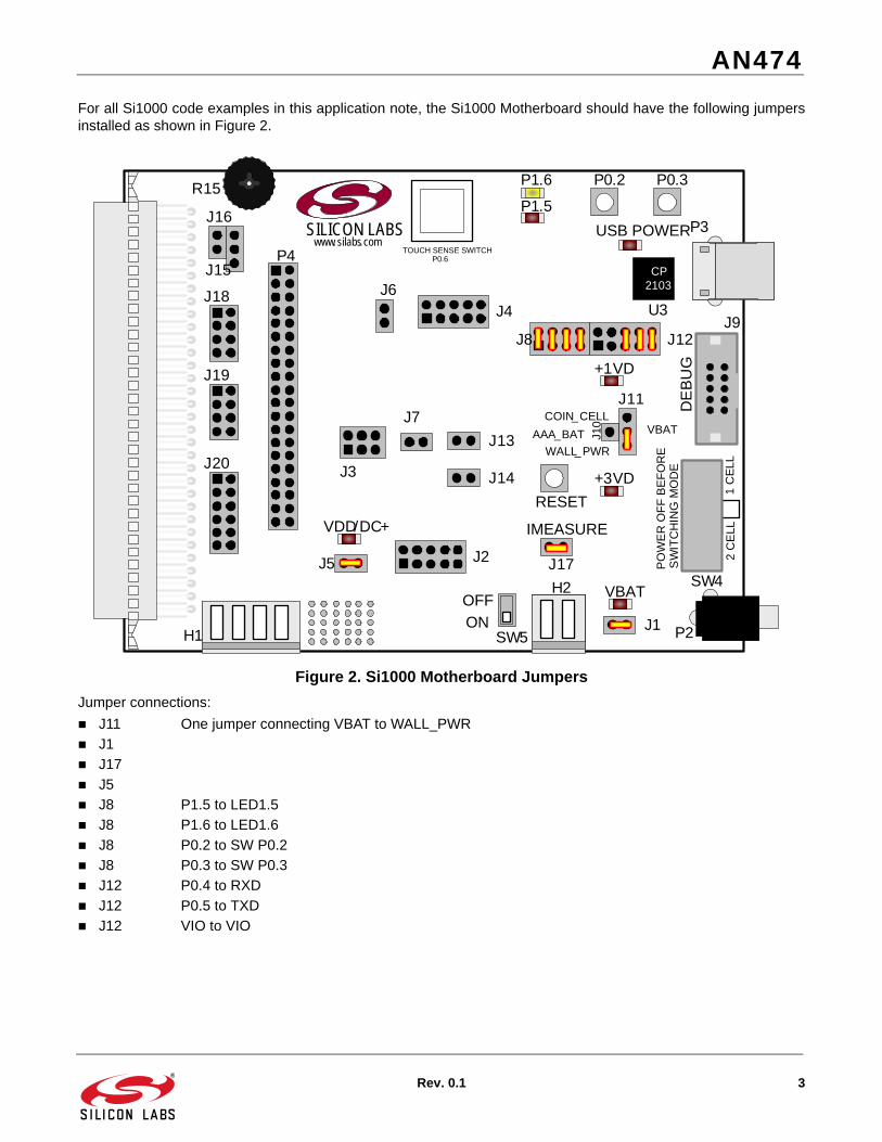
For all Si1000 code examples in this application note, the Si1000 Motherboard should have the following jumpersinstalled as shown in Figure 2.
Figure 2. Si1000 Motherboard Jumpers
Jumper connections:
J11 One jumper connecting VBAT to WALL_PWR
J1
J17
J5
J8 P1.5 to LED1.5
J8 P1.6 to LED1.6
J8 P0.2 to SW P0.2
J8 P0.3 to SW P0.3
J12 P0.4 to RXD
J12 P0.5 to TXD
J12 VIO to VIO
P0.2 P0.3
J3
J4
J2`
P3
CP 2103
U3
P2
DE
BU
G
J9
USB POWER
RESET
P1.6
P1.5
PO
WE
R O
FF
BE
FO
RE
SW4
SW
ITC
HIN
G M
OD
E
2 C
ELL
1 C
EL
L
J17
IMEASURE
H2
SILICON LABSwww. silabs.com
H1
J6
VDD/DC+
J5
J7
J13
P4
J14
J11
J10 VBAT
WALL_PWR
AAA_BAT
COIN_CELL
TOUCH SENSE SWITCHP0.6
J15
J16
R15
J12J8
+3VD
+1VD
VBAT
J1SW5
ON
OFF
J18
J19
J20

AN474
4 Rev. 0.1
The basic steps for running the TX tone example are as follows:
1. Open the TxTone.wsp with the Silicon Labs IDE.
2. Build the project.
3. Download the object file.
4. Run the code example.
5. Make sure the LEDs on the MCU motherboard are blinking.
6. Measure the TX tone power.
The basic steps to evaluate different frequency or power settings are as follows:
1. Open the TX tone project using the IDE.
2. Open the Si100x_TxTone.c file.
3. Edit the frequency or power setting.
4. Build the project.
5. Download the object file.
6. Run the code example.
7. Make sure the LEDs on the MCU motherboard are blinking.
8. Measure the TX tone power.
2.1.2. Write and Read Functions
The most basic primitive function used to write to the radio registers in all of these examples is the phyWrite()function. The “phy” prefix is used to denote the radio physical layer. Some programmers might call this an SPI writefunction. The term, physical layer (PHY), in these code examples is used to denote the software API for thePhysical Layer.
The radio in the Si1000 is connected internally to the SPI1 peripheral of the MCU; so, the radio interface uses thenormal MCU SPI. Detailed information on the SPI interface is available in the Si1000 data sheet. The SPI1peripheral also needs to be configured properly and enabled in the crossbar. Once the SPI and Ports are initialized,writing to the radio is as easy as calling the phyWrite() function.
Reading from the radio is accomplished using the complementary phyRead() function. The phyRead() function isoften used to read status and data.
The radio register names included in the Si1000_defs.h and Si1010_defs.h header files. Note that the registernames are exactly as documented in the data sheet with an EZRADIOPRO_ prefix. The register names areidentical to the Si443x version B1 stand-alone radio. Detailed information on the bit fields can be found in “AN440:Si4430/31/32 Register Descriptions”.
2.1.3. Radio Initialization
The RadioInit() function should be called once after an MCU reset to initialize the radio. The RadioInit() functionprovides debug support to assist in debugging the radio.
The radio has a hardware shut-down (SDN) pin that should be connected either to an MCU port pin or hard-wiredto ground. Connecting the SDN pin to an MCU Port pin provides the lowest possible current consumption with theMCU in Sleep mode and the radio is Shut-Down mode. The code examples are written for a port pin connection butwill still work if SDN is hard wired to ground.
When using the Si1000 daughter card, the SDN pin is connected to P2.6, and the IRQ pin is connected to P0.1.The RadioInit() function returns an error code if the SND pin is not connected to P2.6 or ground. This function alsoreturns an error code if the IRQ pin is not connected to P0.1.
You may have to modify the code example if your hardware uses different port pins for SDN and IRQ. The IRQsignal should always be routed to a P0 port pin so that it may be used with INT0 or INT1. The error codes areintended to provide useful information when debugging new hardware.

AN474
Rev. 0.1 5
After an MCU reset, the state of the radio is unknown. The radio is not automatically reset by an MCU reset. Theradio registers may have some previous settings, and the radio might be in receive or transmit mode. TheRadioInit() function will wait for the entire Power On Reset (POR) duration and then test the status of the Radio. Ifthe radio was not reset from a POR, it will use a software reset.
Upon reset, the MCU port pins are normally configured as inputs with the weak pull-up enabled. However, theweak pull-up is not strong enough to ensure that the radio is reset after an MCU reset. If the radio is going throughthe initial POR sequence, we do not want to shut down the radio; we want to enable it. Therefore, the RadioInit()function will drive the SND pin low to ensure the radio is not shut down.
The SPI communications and radio version are tested by reading the EZRADIOPRO_DEVICE_VERSION. If theradio is held in shutdown mode, the SPI data may read 0xFF.
The reset sequence of the radio will set the EZRADIOPRO_IPOR bit after a reset condition and then set theICHIPRDY bit when the 30 MHz crystal is running. If the IPOR bit is set but the ICHIPRDY bit is not, the MCU willwait with a a 2 millisecond timeout for the ICHIPRDY interrupt.
The RadioInitSoftwareReset() function is used if the radio had not been reset automatically from a POR. This mayoccur if the MCU has been reset by a pin reset or other reset source. The software reset sequence is relativelyquick. A 2 ms timeout is used for the IPOR bit, and an additional 2 ms timeout is used for the ICHIPRDY bit.
This same RadioInit() code is used in all of the Si1000 code examples.
2.1.4. Setting Transmit and Receive Frequency
The setTRxFrequency() function is used to set the radio FREQUENCY_BAND_SELECT andNOMINAL_CARRIER_FREQUENCY registers. To change the frequency, change the default frequency parameter(915000000L) to the desired value and rebuild the project.
The TX Tone example includes run-time code to calculate these register settings based on the frequencyparameter. The equations are taken directly from the register descriptions in the data sheet. ThesetTRxFrequency() function may be used to change the frequency to different values as desired.
The setTRxFrequency() function supports any frequency supported by the Radio (240–960 MHz). The actualfrequency setting will be rounded the closest increment of 625 Hz. The setTRxFrequency() function uses a 32-bitunsigned integer for the frequency parameter and does not support increments less than 625 Hz.
Note that the selected frequency should be appropriate for the Si10xx variant and matching network on theDaughter card. The maximum output power is achieved only when the frequency is the same as the matchingnetwork center frequency, as shown in Table 1.
Table 1. Frequency and Power Settings for Si10xx Daughter Cards
Daughter Board Part Number
Si10xx Variant
Frequency Parameter
Power Parameter
Maximum Output Power
Comment
1000-TCB1C915 Si1000 915000000L 7 +20 dBm
1000-TCB1C470 Si1000 470000000L 7 +20 dBm
1002-TCB1D868 Si1002 868000000L 6 +13 dBm
1002-TCB1D434 Si1002 434000000L 6 +13 dBm
1004-TCB1D868 Si1004 868000000L 6 +13 dBm DC-DC
1004-TCB1D434 Si1004 434000000L 6 +13 dBm DC-DC
1010-TAB1C915 Si1010 915000000L 7 +20 dBm
1010-TAB1C470 Si1010 470000000L 7 +20 dBm
1012-TAB1D868 Si1012 868000000L 6 +13 dBm

AN474
6 Rev. 0.1
2.1.5. Setting TX Power
The SetTXPower() function is a simple function that sets the EZRADIOPRO_TX_POWER register. The transmitpower parameter should normally be set to 7 to achieve full power. The +13 dB variants may need to use a value of6 in order to limit the power to +13 dB maximum, depending on the frequency and quality of the matching network.
2.2. TX Spectrum Code ExampleThe TX Spectrum example is similar to the TX Tone example, except that the TX Spectrum Example generates aspectrum using modulated pseudo-random data.
The TX Spectrum code example is installed by default in the following location:
C:\SiLabs\MCU\Examples\Si100x\EZRadioPRO\TxSpectrum
The test set up is also similar to that shown in Figure 3.
Figure 3. TX Spectrum Test Set-Up
1012-TAB1D434 Si1012 434000000L 6 +13 dBm
1014-TAB1D868 Si1014 868000000L 6 +13 dBm DC-DC
1014-TAB1D434 Si1014 434000000L 6 +13 dBm DC-DC
Table 1. Frequency and Power Settings for Si10xx Daughter Cards (Continued)
Daughter Board Part Number
Si10xx Variant
Frequency Parameter
Power Parameter
Maximum Output Power
Comment
US
B
TxSpectrumWorkspace
Si1000Daughtercard
TxSpectrumFirmware
USBDebug
Adapter
Si1000Motherboard
C2
IDE
PC
SpectrumAnalyzer
RF 50 Ohm Coax

AN474
Rev. 0.1 7
The TX Spectrum may be used to evaluate channel width and channel power and to check against regulation limitsfor out-of-band emissions.
The TX Spectrum example includes run time support for the TX modem registers. The width and shape of thespectrum will depend on the TX modem parameters and the type of modulation selected.
The type of spectrum selected depends on the value of the SPECTRUM_SELECT macro (near the top of the file).The SPECTRUM_SELECT macro may be defined as FSK_SPECTRUM or GFSK_SPECTRUM.
2.2.1. Setting TX Frequency Deviation
The setTxFrequencyDeviation() function is used to configure the Frequency Deviation of the TX Modem. Thedeviation parameter is specified in Hz and will be rounded to the nearest increment of 625 Hz.
2.2.2. Setting TX Data Rate
The setTxDataRate (125000L) sets the data rate of the TX modem. Unsigned 32-bit integer math is used for allrun-time calculations to keep the C code implementation as compact as possible. Special care must be taken toensure that the results of any operation do not exceed 232. The data sheet equations are scaled to keep the resultsof any operation below 232. The resolution is about 1 bps for data rates under 30 kbps. The resolution for datarates above 30 kbps is about 15 bps.
2.3. RX RSSI Code ExampleThe RX RSSI code example is a simple single file example for measuring the RSSI of a received FSK or GFSKsignal. This example provides run-time support for setting the TRx frequency and all RX modem parameters.
The RX RSSI code example is installed by default in the following location:
C:\SiLabs\MCU\Examples\Si100x\EZRadioPRO\RxRSSI\
2.3.1. RSSI Test Set-up
The Test setup for using the RX RSSI code example is shown in Figure 4.
Figure 4. RSSI Test Set-Up
Si1000Daughtercard
RxRSSIFirmware
US
B
USBDebugAdapter
Si1000Motherboard
Hyper-Terminal
RxRSSIWorkspace
TxSpectrumWorkspace
Si1000Daughtercard
TxSpectrumFirmware
USBDebugAdapter
Si1000Motherboard
C2
C2 U
SB
VC
P
US
B
IDE IDE
PC

AN474
8 Rev. 0.1
Measuring the RSSI requires two Si1000 Development Kits. One Si1000 is programmed with the TxSpectrum codeand is used as a generator (an RF signal generator may also be used instead of the transmitter board). The otherSi1000 is programmed with the RxRSSI code and is used as a receiver.
Two instances of the IDE may be used: one for the TxSpectrum code and one for the RxRSSI code. This enablesthe user to easily make changes to the Transmitter and Receiver parameters. It is also possible to leave theTxSpectrum example code running and disconnect the USB debug adapter.
Connect one end of a USB cable to the VCP USB connection on the Motherboard used for the RxRSSI code.Connect the other end to the computer. Open Hyperterminal, select the appropriate COM port, and set thecommunication parameters to 115200-N-1 and no flow control. Connect antennas to both boards. Set up thejumpers as shown in Figure 2. Make sure the jumpers for VIO, TX, and RX are in place since they are required forthe UART connection.
Observe the RSSI measurement while moving the boards further apart. If desired, the TX power may be adjustedon the TxSpectrum code. The frequency and data rate parameters may be changed to match a particularapplication. Remember to use the same settings for both the transmitter and receiver.
2.3.2. Setting TX & RX Frequency
The setTRxFrequency() function is the same as the TxTone and TxSpectrum Examples. The TRx frequency mustalways be set for any transceiver, transmitter, and receiver applications.
2.3.3. Receiver Modem Settings
The register settings for the digital modem receiver are more complex than the transmitter. The receiver registersettings depend on three key receiver User Settings:
RX Data Rate
RX Deviation
RX Bandwidth
The three user settings are used to determine the following radio register settings:
Filter Settings
Over Sampling Ratio
Clock Recovery Offset
Clock Recovery Loop Gain
AFC Limit
2.3.4. RX User Setting Values
Normally, the RX data rate should be set the same as the TX data rate, and the RX deviation should be set to theTX deviation.
The crystal tolerance should be set to the tolerance of the 30 MHz crystal used for the EZRadioPRO in parts permillion (ppm). This should include variation over temperature and aging. In most cases, the crystal is the same forboth transmitter and receiver. If the transmitter and receiver crystals have different tolerances, calculate theaverage tolerance by adding both values and dividing by two.
2.3.5. RX Bandwidth
The RX bandwidth should be calculated using Carsons Rule:
RxBandWidth = TRxFrequency + 2 x RxDeviation.
The AFC can compensate as long as the frequency error is less than 70% of the ideal bandwidth. If the frequencyerror is greater than this value, the bandwidth must be increased. Use the Excel calculator to calculate theRXBandwidth in this case.
Manchester encoded is disabled in all of these code examples. Manchester encoding is not normally necessaryunless it is required for compliance with legacy standards.
AFC is enabled in all of these RF code examples. AFC should normally be enabled unless an extremely shortpreamble is required. With AFC enabled, the RX Bandwidth only needs to be adjusted if the frequency toleranceexceeds the compensation range of the AFC.

AN474
Rev. 0.1 9
2.3.6. Filter Settings
The Filter Settings are determined using a Look-up table based on the RX Bandwidth. The lookUpFilterSetting()function will find the smallest value in the table larger than the target bandwidth. A simple incremental search isused.
The Filter Setting value from the table is the 8-bit value, which is written directly to the IF_FILTER_BANDWIDTHregister. This value is a bit-field composite of three value fields: dwn3_byp, ndec_exp, and filset. These bit-fieldvalues are also used to calculate the remaining receiver register settings.
2.3.7. Over Sampling Ratio
The calcRxoverSamplingRatio() function uses the rxDataRate and the filterSetting value from the look-up table.The equation for the rxOverSamplingRatio can be found in the register definitions. The equation used is differentdepending on the value of dwn3_bypass in the filter setting.
The setRxoverSamplingRatio() function is used to write the calculated value to the appropriate radio registers.Some of the radio modem parameters are split up among the 8-bit radio registers. In this case, the most significant5-bits of the over sampling ratio are combined with other settings in the CLOCK_RECOVERY_OFFSET_2. Toensure that other values are preserved, a read-modify-write operation is used. This involves first reading theregister value using a phyRead(), modifying only the appropriate bits, and writing the value back using a phyWrite()operation.
2.3.8. Clock Recovery Offset
The calcClockrecoverOffset() function also uses the rxDataRate and the filterSetting value from the look-up table.The equation for the rxOverSamplingRatio is adjusted to limit the operands to 32-bits. The clock recovery offset iscalculated to a data rate accuracy of 32 bps.
The setClockrecoverOffset() function is used to write the calculated value to the appropriate radio registers. Theclock recover offset is split up into three registers. The value of CLOCK_RECOVERY_OFFSET_2 is combined withthe over-sampling ratio. Again, a read-modify-write operation is used to preserve the other bits inCLOCK_RECOVERY_OFFSET_2.
2.3.9. Clock Recovery Loop Gain
The Clock Recover Loop gain depends on three parameters: rxDataRate, RxOverSamplingRatio, andRxDeviation; so, the Clock Recovery Loop Gain must be updated if any one of these three parameters is changed.
The clock recover loop gain is split into two registers. The code examples use unions where necessary to make thecode compiler endianness-independent.
2.3.10. AFC Limit
The Receiver Modem includes Automatic Frequency Control (AFC). The AFC Limit register can be used to set theAFC pull in range. The equation to the pull-in range can be found in the data sheet.
The AFC pull-in range is calculated using the RxBandwidth. This assumes than the RxBandwidth has already beenadjusted for the crystal tolerance.
Refer to the Si1000 data sheet for additional information on the AFC Limit.

AN474
10 Rev. 0.1
3. Basic Physical Layer Examples
3.1. Run Time PHYThe Run-Time Phy is a simple EZRadioPRO Physical layer that:
Provides run-time calculations of all radio register settings
Provides a simple API
Supports simple data transmission using the packet handler
The run-time code for setting the radio registers includes support for setting all transmitter and receiver settings.The run-time radio setting functions are similar to the TxSpectrum and RxRSSSI code examples.
The RunTime PHY code example is installed by default in the following location:
C:\SiLabs\MCU\Examples\Si100x\EZRadioPRO\RunTimePHY\
3.1.1. Physical Layer Test Setup
The Test Set-up for the Run-Time and Pre-Processor Physical Layer examples is shown in Figure 5..
Figure 5. Run-Time PHY Test Set-Up
The test set-up requires two development kits, one for the transmitter and one for the receiver. The two motherboards should be connect to two USB debug adapters. The setup can use one PC with two instances of the IDE.When using one PC with two USB debug connectors, it is helpful to label each adapter using the serial number asdisplayed in the “Connection Option…” “Selected Adapter” pull-down menu.
Each Si10xx daughter card should have a suitable antenna. If desired, external interference may be eliminated byusing a cable connection with at least 10 dB of attenuation. The RF input of the Si1000 can handle a maximum of+10 dBm.
Connect a USB cable to the receiver board USB connector. This is used for a Virtual COM Port (VCP) connectionfor the receiver. Open HyperTerminal; select the appropriate COM port, and set the communication parameters to115200-N-1 and no flow control.
Si1000Daughtercard
RunTimePhyRxFirmware
US
B
USBDebugAdapter
Si1000Motherboard
Hyper-Terminal
RunTimePhyRxWorkspace
RunTimePhyTxWorkspace
Si1000Daughtercard
RunTimePhyTxFirmware
USBDebugAdapter
Si1000Motherboard
C2
C2 U
SB
VC
P
US
B
IDE IDE
PC

AN474
Rev. 0.1 11
Open the rtPhyTx workspace, and connect to the development kit motherboard to be used as the transmitter. Setup the jumpers as shown in Figure 2. Build, download, and run the project. Each time the push-button switchconnected to P0.2 is pressed, the transmitter will send one packet. The LED connected to P1.5 will illuminate whilethe packet is being transmitted and will be extinguished if packet transmission was successful.
Open the rtPhyRx workspace and connect to the development kit motherboard you want to use as the receiver. Setup the jumpers as shown in Figure 2. Make sure the jumpers for VIO, TX, and RX are in place as they are requiredfor the UART connection. Build, download, and run the project. The LED connected to P1.5 will illuminate brieflyeach time a packet is received. Each time a packet is received, the Packet length and packet data will be sent overthe UART.
3.1.2. PHY Settings
The PHY settings are fully configurable using a Set interface. Some programmers may call these moduleattributes.
The PHY Setting enumerations are as follows:
TRX_FREQUENCY
TRX_DATA_RATE
TRX_DEVIATION
RX_BANDWIDTH
The PHY settings should only be set using the rtPhySet() function. The parameters for the rtPhySet() function arethe setting enumeration and an unsigned 32-bit value.
The rtPhySet() function provides some limit checking for values that are too large. This is useful for catching errorsbut adds some code overhead. The rtPhySet() function returns an error code if the value is too large(INVALID_VALUE) or the enumeration is not supported (INVALID_ADDRESS). Since the Set function checkslimits, the sub-functions do not have to check parameter limits.
The rtPhySet() will store the setting value into the PHY setting structure. If the radio has not been initialized, thevalue is only stored in RAM. If the radio has already been initialized, the radio register settings will be updated onthe fly.
Note that the radio register values are lost if the radio is in shut-down mode. However, the PHY settings in MCURAM will be retained; so, it is sufficient to set the values once and then initialize the radio after each restart.
For code compactness, the Run-Time PHY does not include a Get function. Normally, the radio values are only set,and there is no reason to get the value. The value from the rtPhySettings structure may be declared as external ifdesired. Users that are concerned about strict module security may choose to implement a Get function.
3.1.3. Radio State Management
The rtPhyInit() function should be called once only after the MCU is reset. This function will manage the initial radiostartup. It is, essentially, the same as the RadioInit() function in the RF test examples. After calling rtPhyInit(), theradio should be in the Idle State.
The rtPhyStandby() will put the radio into standby mode. The radio registers are preserved in standby mode. Thepower consumption of the radio is only a few micro-amps in standby versus a few hundred nano-Amps in shut-down. But it only takes about one milli-second to be ready to transmit data from standby versus about 16 milli-seconds from shut-down mode. The lowest power consumption can be achieved by using shut-down mode andputting the MCU into sleep mode for a few minutes. If the application requires that data be transmitted more oftenthan once a minute, it may be better to use the radio Standby mode.
The rtPhyStandby() may be called at any time after rtPhyInit() as long as the radio is not is shutdown mode. If theradio is in shutdown mode, it will return an error.
The rtPhyIdle() function can be used after rtPhyStandby() to put the radio back into Idle mode.
The rtPhyShutDown() will put the Radio into shutdown mode. Note that, once the radio is in shutdown mode, theSPI is not operational. No function that uses the radio should be called until the radio is restarted using thertPhyReStart() function.
The rtPhyReStart() function can be used to restart the radio after putting it into shutdown mode. Note that restartingis faster than starting because the radio is in a known state; so, a timeout may be used for the radio POR delay.
AN474
12 Rev. 0.1
3.1.4. Radio Register Initialization
The rtPhyInitRadio() initializes all of the radio registers based on the current PHY settings. Normally, all of the PHYsettings should be set first before calling rtPhyInitRadio(). This uses fewer cycles than attempting to set allparameters on the fly. The rtPhyInitRadio() function must be called before attempting to transmit or receive.
After Shutting down, all of the radio register values will be lost. After calling rtPhyReStart(), the rtPhyInitRadio()function should be used again to restore the radio register values. Note that the PHY settings are stored in theMCU and are not lost in radio Shut Down mode.
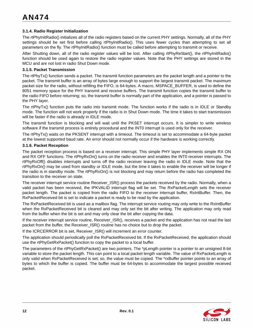
3.1.5. Packet Transmission
The rtPhyTx() function sends a packet. The transmit function parameters are the packet length and a pointer to thepacket. The transmit buffer is an array of bytes large enough to support the largest transmit packet. The maximumpacket size for the radio, without refilling the FIFO, is 64-bytes. A macro, MSPACE_BUFFER, is used to define the8051 memory space for the PHY transmit and receive buffers. The transmit function copies the transmit buffer tothe radio FIFO before returning; so, the transmit buffer is normally part of the application, and a pointer is passed tothe PHY layer.
The rtPhyTx() function puts the radio into transmit mode. The function works if the radio is in IDLE or Standbymode. The function will not work properly if the radio is in Shut Down mode. The time it takes to start transmissionwill be faster if the radio is already in IDLE mode.
The transmit function is blocking and will wait until the PKSET interrupt occurs. It is simpler to write wirelesssoftware if the transmit process is entirely procedural and the INT0 interrupt is used only for the receiver.
The rtPhyTx() waits on the PKSENT interrupt with a timeout. The timeout is set to accommodate a 64-byte packetat the lowest supported baud rate. An error should not normally occur if the hardware is working correctly.
3.1.6. Packet Reception
The packet reception process is based on a receiver interrupt. This simple PHY layer implements simple RX ONand RX OFF functions. The rtPhyRxOn() turns on the radio receiver and enables the INT0 receiver interrupts. ThertPhyRxOff() disables interrupts and turns off the radio receiver leaving the radio in IDLE mode. Note that thertPhyRxOn() may be used from standby or IDLE mode, but the time it takes to enable the receiver will be longer ifthe radio is in standby mode. The rtPhyRxOn() is not blocking and may return before the radio has completed thetransition to the receiver on state.
The receiver interrupt service routine Receiver_ISR() process the packets received by the radio. Normally, when avalid packet has been received, the IPKVALID interrupt flag will be set. The RxPacketLength sets the receiverpacket length. The packet is copied from the radio FIFO to the receiver interrupt buffer, RxIntBuffer. Then, theRxPacketReceived bit is set to indicate a packet is ready to be read by the application.
The RxPacketReceived bit is used as a mailbox flag. The interrupt service routing may only write to the RxIntBufferwhen the RxPacketReceived bit is cleared and may only set the bit after writing. The application may only readfrom the buffer when the bit is set and may only clear the bit after copying the data.
If the receiver interrupt service routine, Receiver_ISR(), receives a packet and the application has not read the lastpacket from the buffer, the Receiver_ISR() routine has no choice but to drop the packet.
If the ICRCERROR bit is set, Receiver_ISR() will increment an error counter.
The application should periodically poll the RxPacketReceived bit. If the RxPacketReceived, the application shoulduse the rtPhyGetRxPacket() function to copy the packet to a local buffer.
The parameters of the rtPhyGetRxPacket() are two pointers. The *pLength pointer is a pointer to an unsigned 8-bitvariable to store the packet length. This can point to a local packet length variable. The value of RxPacketLength isonly valid when RxPacketReceived is set; so, the value must be copied. The *rxBuffer pointer points to an array ofbytes to which the buffer is copied. The buffer must be 64-bytes to accommodate the largest possible receivedpacket.
AN474
Rev. 0.1 13
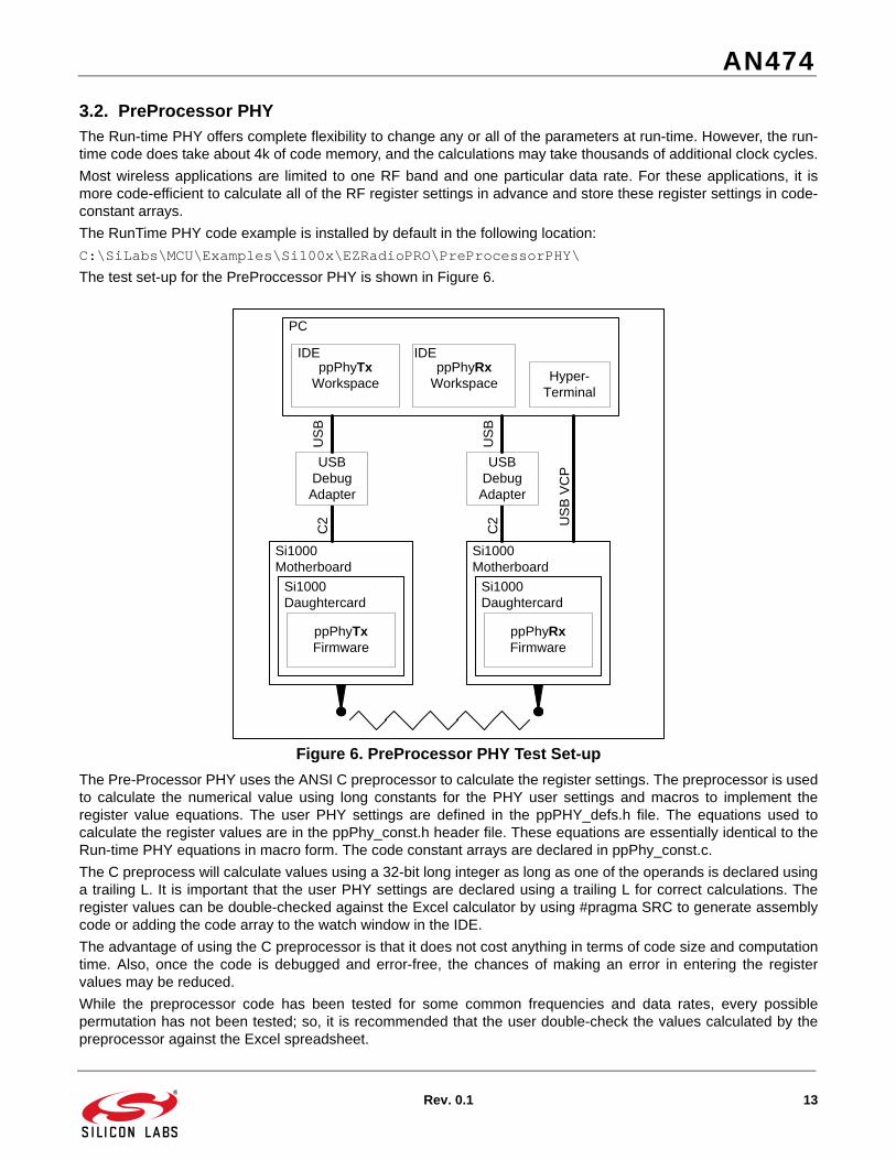
3.2. PreProcessor PHYThe Run-time PHY offers complete flexibility to change any or all of the parameters at run-time. However, the run-time code does take about 4k of code memory, and the calculations may take thousands of additional clock cycles.
Most wireless applications are limited to one RF band and one particular data rate. For these applications, it ismore code-efficient to calculate all of the RF register settings in advance and store these register settings in code-constant arrays.
The RunTime PHY code example is installed by default in the following location:
C:\SiLabs\MCU\Examples\Si100x\EZRadioPRO\PreProcessorPHY\
The test set-up for the PreProccessor PHY is shown in Figure 6.
Figure 6. PreProcessor PHY Test Set-up
The Pre-Processor PHY uses the ANSI C preprocessor to calculate the register settings. The preprocessor is usedto calculate the numerical value using long constants for the PHY user settings and macros to implement theregister value equations. The user PHY settings are defined in the ppPHY_defs.h file. The equations used tocalculate the register values are in the ppPhy_const.h header file. These equations are essentially identical to theRun-time PHY equations in macro form. The code constant arrays are declared in ppPhy_const.c.
The C preprocess will calculate values using a 32-bit long integer as long as one of the operands is declared usinga trailing L. It is important that the user PHY settings are declared using a trailing L for correct calculations. Theregister values can be double-checked against the Excel calculator by using #pragma SRC to generate assemblycode or adding the code array to the watch window in the IDE.
The advantage of using the C preprocessor is that it does not cost anything in terms of code size and computationtime. Also, once the code is debugged and error-free, the chances of making an error in entering the registervalues may be reduced.
While the preprocessor code has been tested for some common frequencies and data rates, every possiblepermutation has not been tested; so, it is recommended that the user double-check the values calculated by thepreprocessor against the Excel spreadsheet.
Si1000Daughtercard
ppPhyRxFirmware
US
B
USBDebugAdapter
Si1000Motherboard
Hyper-Terminal
ppPhyRxWorkspace
ppPhyTxWorkspace
Si1000Daughtercard
ppPhyTxFirmware
USBDebugAdapter
Si1000Motherboard
C2
C2 U
SB
VC
P
US
B
IDE IDE
PC
AN474
14 Rev. 0.1
3.2.1. PHY Initialization
The ppPhyInitRadio() function will write all of the values in the ppPhySettings array to the registers in theppPhyRegisters array. The values in the ppPhySettings array are calculated by the C preprocessor. These twoarrays also have build options for a TRANSMITTER_ONLY or RECEIVER_ONLY build. This reduces the code sizeby an additional few bytes and saves a few instructions.
Note that ppPhyInitRadio() does not calculate the register values. The values are already calculated by the Cpreprocessor. However, many bytes are written to the radio to set the registers.
The ppPhyInitRadio() should be called after ppPhyInit(). Again, the radio register values are not persistent if theradio is put into shutdown mode; so, ppPhyInitRadio() should be called after ppPhyReStart().
The Pre-Processor PHY does not have a Set function. The user settings are defined in the ppPhy_defs.h file. Theproject must be recompiled after changing one of the user settings.
3.2.2. Radio Power Modes
The radio power mode management functions are the same as the Run-time PHY.
3.2.3. Transmission and Reception
The transmission and reception functions are the same as the Run-Time PHY.

http://www.silabs.com
Silicon Laboratories Inc.400 West Cesar ChavezAustin, TX 78701USA
Simplicity Studio
One-click access to MCU and wireless tools, documentation, software, source code libraries & more. Available for Windows, Mac and Linux!
IoT Portfoliowww.silabs.com/IoT
SW/HWwww.silabs.com/simplicity
Qualitywww.silabs.com/quality
Support and Communitycommunity.silabs.com
DisclaimerSilicon Labs intends to provide customers with the latest, accurate, and in-depth documentation of all peripherals and modules available for system and software implementers using or intending to use the Silicon Labs products. Characterization data, available modules and peripherals, memory sizes and memory addresses refer to each specific device, and "Typical" parameters provided can and do vary in different applications. Application examples described herein are for illustrative purposes only. Silicon Labs reserves the right to make changes without further notice and limitation to product information, specifications, and descriptions herein, and does not give warranties as to the accuracy or completeness of the included information. Silicon Labs shall have no liability for the consequences of use of the information supplied herein. This document does not imply or express copyright licenses granted hereunder to design or fabricate any integrated circuits. The products are not designed or authorized to be used within any Life Support System without the specific written consent of Silicon Labs. A "Life Support System" is any product or system intended to support or sustain life and/or health, which, if it fails, can be reasonably expected to result in significant personal injury or death. Silicon Labs products are not designed or authorized for military applications. Silicon Labs products shall under no circumstances be used in weapons of mass destruction including (but not limited to) nuclear, biological or chemical weapons, or missiles capable of delivering such weapons.
Trademark InformationSilicon Laboratories Inc.® , Silicon Laboratories®, Silicon Labs®, SiLabs® and the Silicon Labs logo®, Bluegiga®, Bluegiga Logo®, Clockbuilder®, CMEMS®, DSPLL®, EFM®, EFM32®, EFR, Ember®, Energy Micro, Energy Micro logo and combinations thereof, "the world’s most energy friendly microcontrollers", Ember®, EZLink®, EZRadio®, EZRadioPRO®, Gecko®, ISOmodem®, Precision32®, ProSLIC®, Simplicity Studio®, SiPHY®, Telegesis, the Telegesis Logo®, USBXpress® and others are trademarks or registered trademarks of Silicon Labs. ARM, CORTEX, Cortex-M3 and THUMB are trademarks or registered trademarks of ARM Holdings. Keil is a registered trademark of ARM Limited. All other products or brand names mentioned herein are trademarks of their respective holders.