O Scale West presentation 2012 -- handlaying turnouts ...
34
Handlaying Turnouts Point, Stub, and Exotic Wayne Perrier O Scale West 2012 www.americantieandtimber.com 1 Examples We’ll Cover Today O Scale West 2012 www.americantieandtimber.com 2 Point Switches
Transcript of O Scale West presentation 2012 -- handlaying turnouts ...

Handlaying TurnoutsPoint, Stub, and Exotic
Wayne Perrier
O Scale West 2012 www.americantieandtimber.com 1
Examples We’ll Cover Today
O Scale West 2012 www.americantieandtimber.com 2
Point Switches

Examples We’ll Cover Today
O Scale West 2012 www.americantieandtimber.com 3
Stub Switches
• We’re going to “build” this today!
Examples We’ll Cover Today
O Scale West 2012 www.americantieandtimber.com 4
Switch on a Trestle
The Problem• Traditional “insulated rail joiners” are unsightly
• They don’t do a good job of holding rails in alignment in ANY direction x,y, z –derailments can happen.
• They can allow the rails to spread further apart, increasing the gap
Gapping Rails: Challenges
O Scale West 2012 www.americantieandtimber.com 5
• They are generally so beefy due to the material characteristics that wheel flanges can hit them, particularly with smaller rail sizes like code70
Cutting a gap in flextrack or handlaid has its own problems• Gap can close, causing electrical problems
• Gaps can open, looking unsightly or causing derailments
• Alignment can be poor, especially over time
Is there a solution?
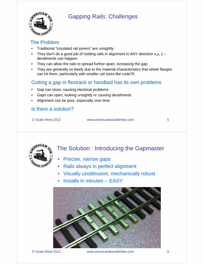
• Precise, narrow gaps
• Rails always in perfect alignment
• Visually unobtrusive, mechanically robust
• Installs in minutes -- EASY
The Solution : Introducing the Gapmaster
O Scale West 2012 www.americantieandtimber.com 6
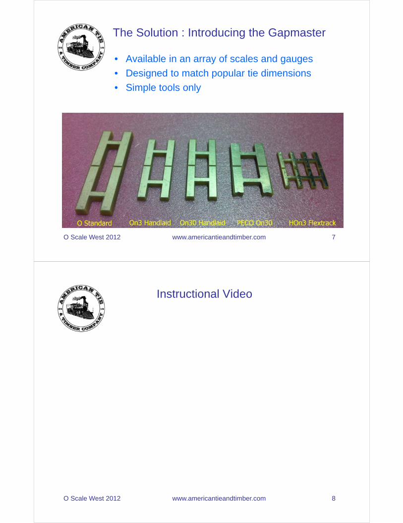
• Available in an array of scales and gauges
• Designed to match popular tie dimensions
• Simple tools only
The Solution : Introducing the Gapmaster
O Scale West 2012 www.americantieandtimber.com 7
Instructional Video
O Scale West 2012 www.americantieandtimber.com 8
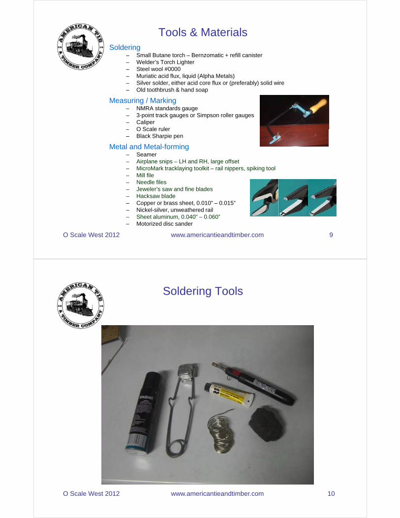
Soldering– Small Butane torch – Bernzomatic + refill canister– Welder’s Torch Lighter– Steel wool #0000– Muriatic acid flux, liquid (Alpha Metals)– Silver solder, either acid core flux or (preferably) solid wire– Old toothbrush & hand soap
Measuring / Marking– NMRA standards gauge– 3-point track gauges or Simpson roller gauges– Caliper– O Scale ruler
Tools & Materials
O Scale West 2012 www.americantieandtimber.com 9
– O Scale ruler– Black Sharpie pen
Metal and Metal-forming– Seamer– Airplane snips – LH and RH, large offset– MicroMark tracklaying toolkit – rail nippers, spiking tool– Mill file– Needle files– Jeweler’s saw and fine blades– Hacksaw blade– Copper or brass sheet, 0.010” – 0.015”– Nickel-silver, unweathered rail– Sheet aluminum, 0.040” – 0.060”– Motorized disc sander
Soldering Tools
O Scale West 2012 www.americantieandtimber.com 10

Frog Soldering Jig– Allows soldering the 4 rails that comprise the frog into a unitized
assembly
– Adapted from 1970’s article in Model Railroader magazine about handlaying code 40 N Scale turnouts in place.
Simple Jigs to Make
O Scale West 2012 www.americantieandtimber.com 11
– Masonite base
Guardrail Spacing Jig– Allows easy spacing and alignment of guardrails
– Simple aluminum plate that grips guardrail and stock rail
– Use NMRA gauge, caliper and jewelers saw to fashion this.
Stub Rail Spacing Jig– Allows easy spacing and alignment of stub switch rails.
– Aluminum plate grips 2 or 3 rails at a time over the soldering point
Frog Soldering Jig
Simple Jigs to Make
O Scale West 2012 www.americantieandtimber.com 12
Guardrail Spacing Jig
Stub Rail Spacing Jig
What is Nickel Silver?
Nickel silver is a metal alloy of copper with nickel and often but not always zinc. It is named for its silvery appearance, but contains no elemental silver unless plated. Other common names for this alloy are German silver, paktong, new silver and alpacca(or alpaca).
Composition
According to Wikipedia:
O Scale West 2012 www.americantieandtimber.com 13
Many alloys fall within the general term of "nickel silver". All contain copper and nickel, while some formulations may additionally include zinc, antimony, tin, lead, or cadmium. A representative industrial formulation, Alloy No. 752, is 65% copper, 18% nickel, and 17% zinc. The white alloy of 75% copper and 25% nickel used in coins, such as the United States nickel, is better known as copper-nickel, cupro-nickel or cupronickel.Some nickel silver alloys, especially those containing high proportions of zinc, are stainless (corrosion-resistant).Nickel silver alloys are commonly named by listing their percentages of copper and nickel, thus "nickel silver 55-18" would contain 55% copper, 18% nickel, and 27% other elements, most probably entirely zinc. A two-element alloy may be named for its nickel content alone, thus NS-12 is 88% copper and 12% nickel.
• All model rail is not created equally
• Different alloys of nickel-silver used, resulting in different colours of rail
• You will notice some websites talk about RailCraft rail versus new
Some Notes About Model Rail
O Scale West 2012 www.americantieandtimber.com 14
Micro Engineering (ME) rail
• Different railhead widths and different rail base widths
• Different size rail-joiners over the years
• The weathering on ME rail has been inconsistent recently
• I prefer to weather it myself – I use the ME rail weathering solution

• 2 methods possible:– Dunk rail in a vat and agitate, or,– Paint solution onto rail and wait– Both are reasonable methods
• Why “do-it-yourself”?– To obtain the exact colour you want
Using ME Rail-Weathering Solution
O Scale West 2012 www.americantieandtimber.com 15
– To get a consistent colour– To enable starting with bare metal for better soldering
• Steps– Mask off bottom of rail in areas where feeder wires will be
soldered. I use blue masking tape strips– Fill vat with solution; place in rail pieces and agitate until
desired colour achieved– Rinse well with water and let dry; use 72 hours later
• Always inspect all your rail at time of purchase– Note the colour and width of railhead and base– Your hobby shop will love you for this.
• Never use pre-weathered rail for your soldered switchwork – It does not solder well and is impossible to fully clean off
• Never rely on rail joiners for positive electrical contact
Always and Never
O Scale West 2012 www.americantieandtimber.com 16
• Always solder 2 feeder wires to the bottom of each rail – One is redundant
• Always colour-code your feeder wires– I use black for -, red for +, and white for frogs
• Always use silver-solder, never lead-tin– It is considerably stronger
• Always build your switches to be DCC-compatible– This is easy to do
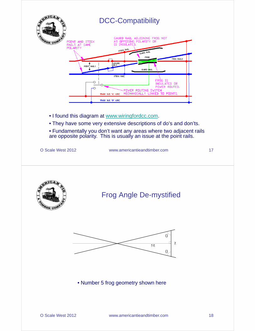
DCC-Compatibility
O Scale West 2012 www.americantieandtimber.com 17
• I found this diagram at www.wiringfordcc.com.
• They have some very extensive descriptions of do’s and don’ts.
• Fundamentally you don’t want any areas where two adjacent rails are opposite polarity. This is usually an issue at the point rails.
Frog Angle De-mystified
O Scale West 2012 www.americantieandtimber.com 18
• Number 5 frog geometry shown here

Standard 2-way Point Switch
Note gaps
O Scale West 2012 www.americantieandtimber.com 19
• Quick to build• Involves basic principles we can apply to other switches
Curved Point Switch
O Scale West 2012 www.americantieandtimber.com 20
• Surprisingly common on prototype• Frog angles generally very acute

Cutting Rail
• Rough-cut to approximate length + 1/16” - 1/8”
• Complete finish-cut
• Ensure that cutter blade held vertical
• Inspect
Note
O Scale West 2012 www.americantieandtimber.com 21
Bending Rail
• Use MicroMark spiking pliers to firmly grip railhead and base at same time
• Keeping tight grip, bend protruding rail with fingers
• Railhead will be centered with respect to base after bend
• Touchup underneath rail with fine file to remove “bumps”
O Scale West 2012 www.americantieandtimber.com 22

Bending Rail: Don’t use Needlenose
• Needlenose will result in a deformed bend
• Base is bent and railhead “along for the ride”
• Not recommended
Note: rail head not centered on
Note: rail head not gripped by
O Scale West 2012 www.americantieandtimber.com 23
not centered on base
not gripped by pliers
Building a Frog: Step1
• Setup your disc sander
O Scale West 2012 www.americantieandtimber.com 24

Building a Frog: Step2
• Cut frog diverging rails to desired length. I prefer 8 inches• Rails can be different codes if required• Sand rails to sharp point using disc sander• Check angle against frog lines on jig – test fit often• Touch up with steel wool and files• Solder together lightly with silver solder and acid• Clean with toothbrush, hot water and soap• Use mill file to touchup and sharpen to a point
O Scale West 2012 www.americantieandtimber.com 25
Building a Frog: Step3
• Cut 2 pieces of rail about 8 inches long
• Form closure rails using MicroMark spiking pliers
• Form to appropriate frog angle
O Scale West 2012 www.americantieandtimber.com 26

Building a Frog: Step4• Cut out copper plate; ensure flat; polish with steel wool• Place copper plate in jig, put a few drops of liquid flux on it• Polish bottoms of rails with steel wool in frog area; place all rails in jig• Tighten carefully; use NMRA gauge to set flangeway widths• Eyeball the alignment – straightedge could be used• Ensure all rails are laying flat
O Scale West 2012 www.americantieandtimber.com 27
Building a Frog: Step4 Continued• Apply torch heat to one side of plate• Let it heat up a bit – flux will bubble vigourously• Apply solder to opposing side of plate• Solder will flow toward heat source, across plate and under rail• Do not over-apply solder. It should contact plate and bottom of rails only.• When you see the solder creeping along all edges of rail, remove heat and solder source. Let cool.
O Scale West 2012 www.americantieandtimber.com 28
Building a Frog: Step5
• Remove frog from jig• Rinse under hot water; scrub with toothbrush and soap to remove flux and contaminants• Pat dry with towel
S b f ith t l l
O Scale West 2012 www.americantieandtimber.com 29
• Scrub frog with steel wool• Cut away excess copper with airplane snips and files
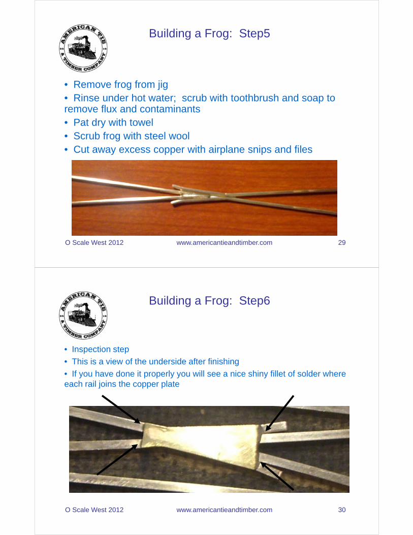
Building a Frog: Step6
• Inspection step
• This is a view of the underside after finishing
• If you have done it properly you will see a nice shiny fillet of solder where each rail joins the copper plate
O Scale West 2012 www.americantieandtimber.com 30
Building a Guardrail: Step1
• Mark guardrail length and position using Sharpie pen.• Cut copper plate for length of guardrail; cut and bend guardrail• Ensure it is flat; polish with steel wool; apply acid and place on masonite• Polish bottom of rails with steel wool• Place on masonite
O Scale West 2012 www.americantieandtimber.com 31
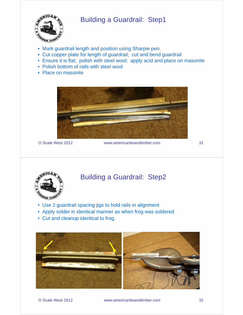
Building a Guardrail: Step2
• Use 2 guardrail spacing jigs to hold rails in alignment• Apply solder in identical manner as when frog was soldered• Cut and cleanup identical to frog.
O Scale West 2012 www.americantieandtimber.com 32

Building a Guardrail: Step3
• This is a view of the underside after finishing
• If you have done it properly you will see a nice shiny fillet of solder at each end
O Scale West 2012 www.americantieandtimber.com 33
Building a “point switch” Throwbar: Step1
• I use double-sided, 0.062” copper-clad FR4 PCB material• I cut it into strips on my DeWalt mitre saw (slooowly)• Touchup with a big mill file• Cut to length with snips and touchup with mill file• I only drill holes to actuate harp switch stands, not for switch machine• Gap top with jeweler’s saw• Polish with steel wool and silver solder to points (we will cover this later)• Turn assembly over and solder linkage bracket to underside (for Tortoise)
O Scale West 2012 www.americantieandtimber.com 34
Turn assembly over and solder linkage bracket to underside (for Tortoise)
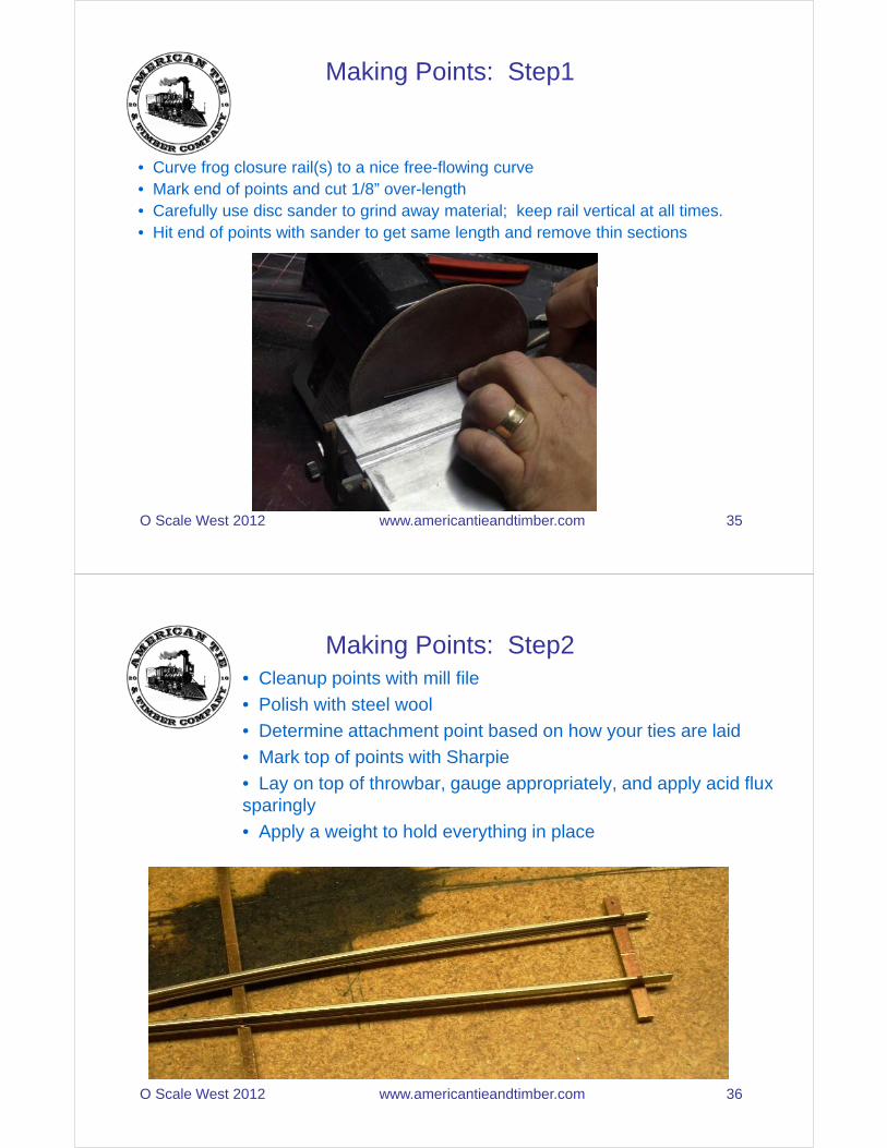
Making Points: Step1
• Curve frog closure rail(s) to a nice free-flowing curve• Mark end of points and cut 1/8” over-length• Carefully use disc sander to grind away material; keep rail vertical at all times.• Hit end of points with sander to get same length and remove thin sections
O Scale West 2012 www.americantieandtimber.com 35
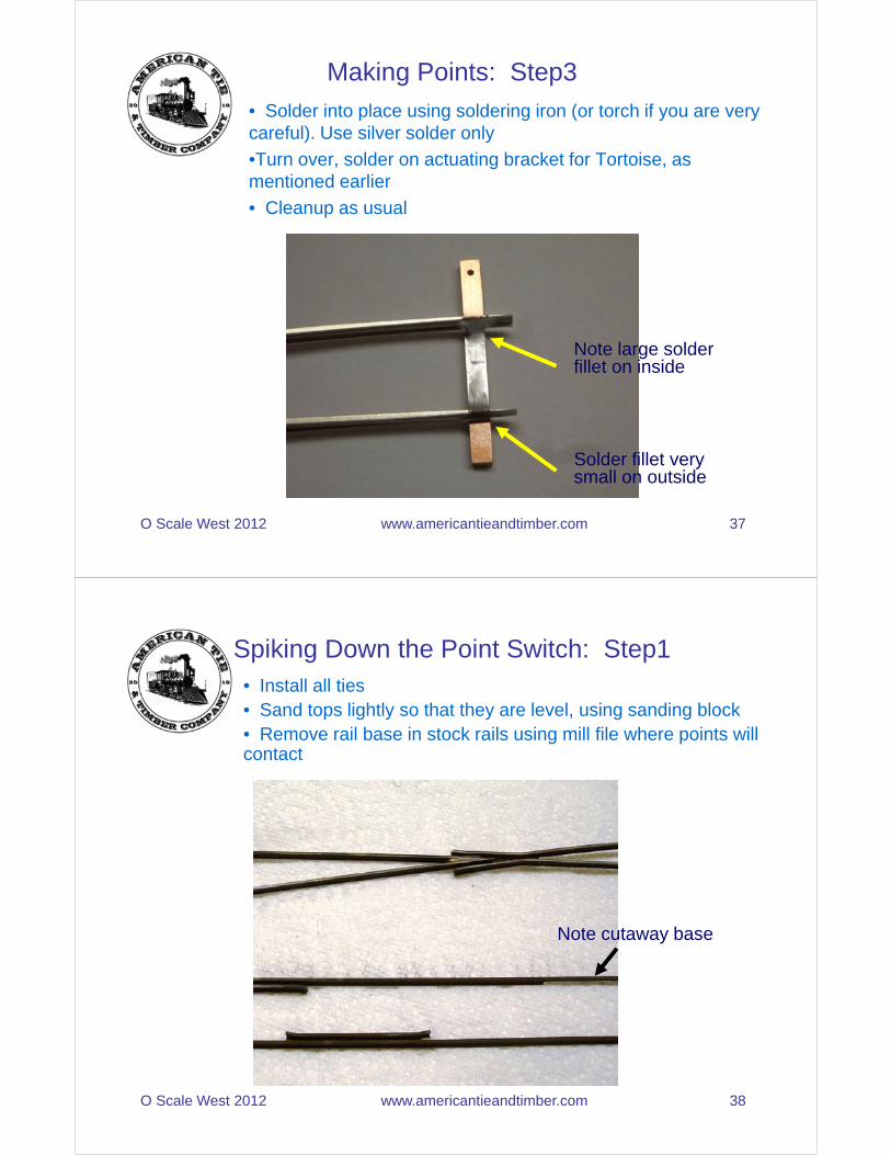
Making Points: Step2• Cleanup points with mill file
• Polish with steel wool
• Determine attachment point based on how your ties are laid
• Mark top of points with Sharpie
• Lay on top of throwbar, gauge appropriately, and apply acid fluxsparingly
• Apply a weight to hold everything in place
O Scale West 2012 www.americantieandtimber.com 36
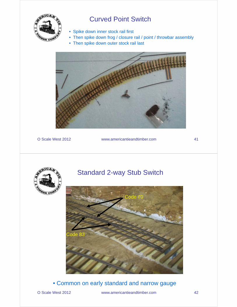
Making Points: Step3
• Solder into place using soldering iron (or torch if you are very careful). Use silver solder only
•Turn over, solder on actuating bracket for Tortoise, as mentioned earlier
• Cleanup as usual
O Scale West 2012 www.americantieandtimber.com 37
Note large solder fillet on inside
Solder fillet very small on outside
Spiking Down the Point Switch: Step1• Install all ties• Sand tops lightly so that they are level, using sanding block• Remove rail base in stock rails using mill file where points will contact
O Scale West 2012 www.americantieandtimber.com 38
Note cutaway base

Spiking Down the Point Switch: Step2
• Cutaway ties from under guardrail area.
• Solder feeder wires onto rail bottom using rosin-core silver solder
• Spike down straight stock rail
O Scale West 2012 www.americantieandtimber.com 39
Spiking Down the Point Switch: Step3
• Solder 2 white feeder wires to the frog, after it• Solder red and black feeder wires to closure rails, ahead of where you will gap• Gauge the frog to straight stock rail and spike into place• Do not cut any gaps now
O Scale West 2012 www.americantieandtimber.com 40
y g p• Then spike the curved stock rail into place• Gap using jeweller’s saw just forward of frog on both closure rails – this generally involves making a hole in the roadbed• Install switch machine and test• Ballast
Curved Point Switch
• Spike down inner stock rail first• Then spike down frog / closure rail / point / throwbar assembly• Then spike down outer stock rail last
O Scale West 2012 www.americantieandtimber.com 41
Standard 2-way Stub Switch
Code 70
O Scale West 2012 www.americantieandtimber.com 42
• Common on early standard and narrow gauge
Code 83

3-Way Stub Switch
O Scale West 2012 www.americantieandtimber.com 43
• Common on narrow-gauge and turn-of-the-century standard gauge
• Highly interesting trackage feature – exotic
• Not as hard to build as you might think
3-Way Stub Switch: Step1
• Create 2 frogs of the desired angle using frog jig:
O Scale West 2012 www.americantieandtimber.com 44
• As always, leave the rails fairly long – 8-9 inches or more
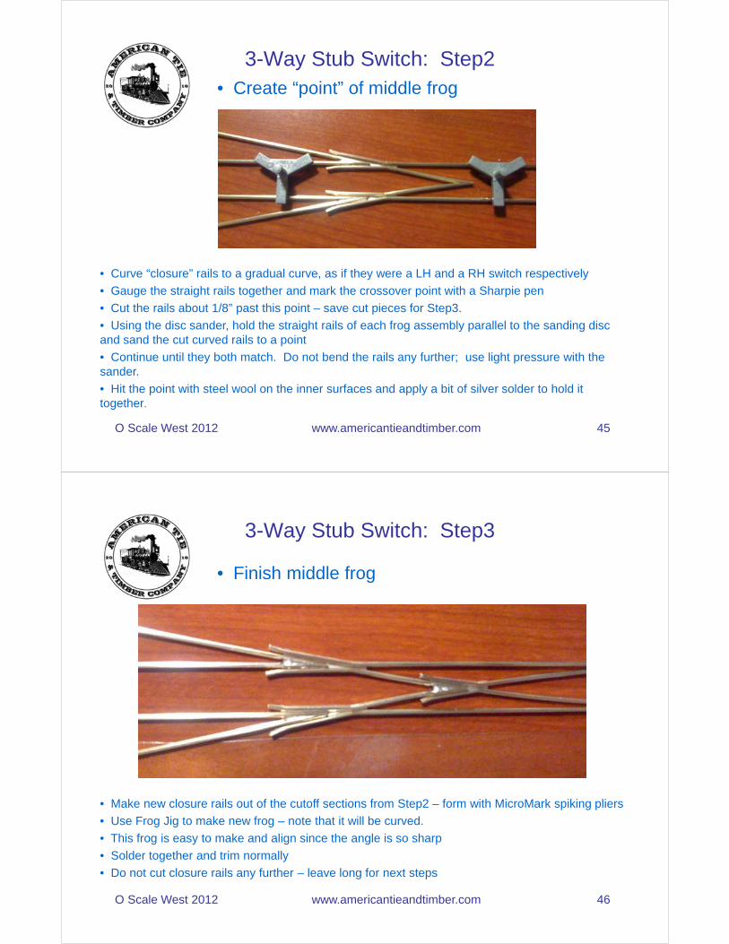
3-Way Stub Switch: Step2• Create “point” of middle frog
O Scale West 2012 www.americantieandtimber.com 45
• Curve “closure” rails to a gradual curve, as if they were a LH and a RH switch respectively
• Gauge the straight rails together and mark the crossover point with a Sharpie pen
• Cut the rails about 1/8” past this point – save cut pieces for Step3.
• Using the disc sander, hold the straight rails of each frog assembly parallel to the sanding disc and sand the cut curved rails to a point
• Continue until they both match. Do not bend the rails any further; use light pressure with the sander.
• Hit the point with steel wool on the inner surfaces and apply a bit of silver solder to hold it together.
3-Way Stub Switch: Step3
• Finish middle frog
O Scale West 2012 www.americantieandtimber.com 46
• Make new closure rails out of the cutoff sections from Step2 – form with MicroMark spiking pliers
• Use Frog Jig to make new frog – note that it will be curved.
• This frog is easy to make and align since the angle is so sharp
• Solder together and trim normally
• Do not cut closure rails any further – leave long for next steps
3-Way Stub Switch: Step4
• Bend stock rails to approximate curve
O Scale West 2012 www.americantieandtimber.com 47
• Get close – we can adjust later
• These should be long rails, 2-5 inches longer than necessary for the switch
3-Way Stub Switch: Step5
• Solder on Guard Rails to Stock Rails
O Scale West 2012 www.americantieandtimber.com 48
• Try to curve these to match the stock rails
• Alternatively you can solder straight guardrails to straight stock rails and carefully curve later
• Prior to soldering mark guardrail positions using Sharpie on rail head

3-Way Stub Switch: Step6
• Align for final assembly
O Scale West 2012 www.americantieandtimber.com 49
• Use stub rail jig and track gauges to align all 3 routes
• Make sure that guardrails align with frogs
• Mark tops of rails with Sharpie at alignment tool
• Cut rails carefully at marks – you only get one shot at this – practice if you need to
3-Way Stub Switch: Step7
• Solder on baseplates for stub rails
O Scale West 2012 www.americantieandtimber.com 50
• Use solder sparingly
• Don’t worry about length and width initially – see bottom copper plate
• Cleanup with file after soldering; cut to size with airplane snips
• Perform this soldering with spacing jig and track gauges to guarantee alignment
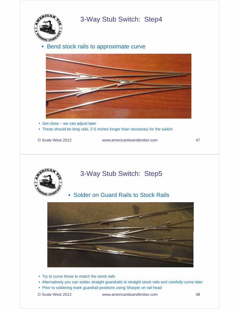
3-Way Stub Switch: Step8• Solder on Rail Stops
O Scale West 2012 www.americantieandtimber.com 51
• Solder to bottom of previously-soldered copper plate
• Sharply bent piece of copper
• Use solder sparingly
• Provides a positive stop for moveable rails
• Do not use too much heat – avoid undoing previous soldering
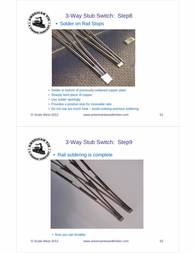
3-Way Stub Switch: Step9
• Rail soldering is complete
O Scale West 2012 www.americantieandtimber.com 52
• Now you can breathe.
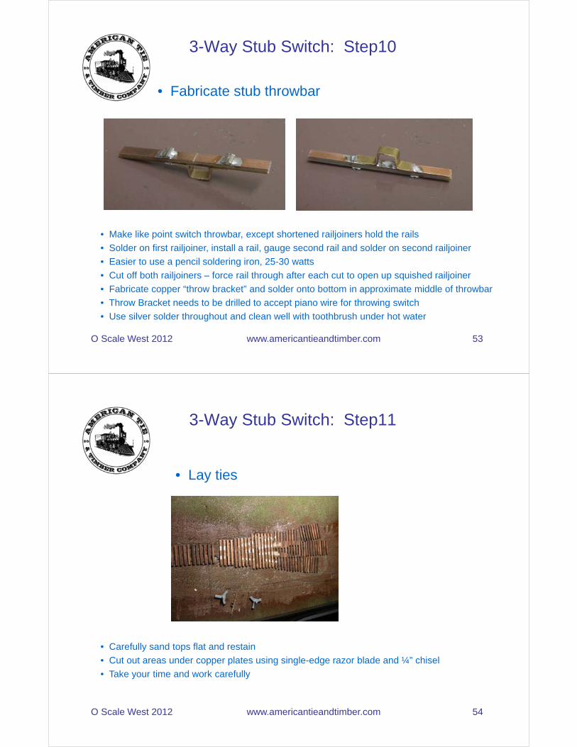
3-Way Stub Switch: Step10
• Fabricate stub throwbar
O Scale West 2012 www.americantieandtimber.com 53
• Make like point switch throwbar, except shortened railjoiners hold the rails
• Solder on first railjoiner, install a rail, gauge second rail and solder on second railjoiner
• Easier to use a pencil soldering iron, 25-30 watts
• Cut off both railjoiners – force rail through after each cut to open up squished railjoiner
• Fabricate copper “throw bracket” and solder onto bottom in approximate middle of throwbar
• Throw Bracket needs to be drilled to accept piano wire for throwing switch
• Use silver solder throughout and clean well with toothbrush under hot water
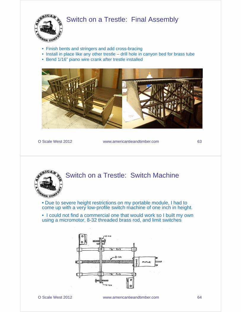
3-Way Stub Switch: Step11
• Lay ties
O Scale West 2012 www.americantieandtimber.com 54
• Carefully sand tops flat and restain
• Cut out areas under copper plates using single-edge razor blade and ¼” chisel
• Take your time and work carefully

3-Way Stub Switch: Step12
• Spike down rails
O Scale West 2012 www.americantieandtimber.com 55
• Do not perform any gapping, under any circumstances at this point
• Pre-solder on your feeder wires, like any other switch – there will be more of them
• Note that rails have been pre-weathered
• Use plenty of spikes
• Take great care to ensure that switch is in gauge everywhere – use NMRA gauge to check
3-Way Stub Switch: Step13
• Cut gaps using razor saw, dremel or jeweler’s saw
O Scale West 2012 www.americantieandtimber.com 56
• You will need to cut 5 gaps inside of the switch itself, and gap the frog rails beyond the switch
• Ensure before gapping that you have spikes on both sides of the gap to maintain alignment
• Ballast as necessary
• Go out and celebrate

Switch on a Trestle
O Scale West 2012 www.americantieandtimber.com 57
• Not common on prototype but highly cool• How did you power that throwbar anyway?
Switch on a Trestle: The Rails
• Buildup “switch kit” as usual but solder wires across the underside of stock rails and closure rails as shown below. Use silver solder and weather these.
O Scale West 2012 www.americantieandtimber.com 58
• These provide power to the points

Switch on a Trestle: Throwbar
• Throwbar same as before but tab underneath a little different.
O Scale West 2012 www.americantieandtimber.com 59
Note nice solder fillet
Switch on a Trestle: Deck
• Weather switch and spike into place on deck.
O Scale West 2012 www.americantieandtimber.com 60
• Keep rails extra-long – all feeder wires are on bridge approaches• Now is a good time to check alignment

Switch on a Trestle: Subassemblies• Prefab all subassemblies – use disc sander to obtain clean angles• Note brass tube in middle bent – 12x12 post is actually a box made up of 4 pieces• Tube inner diameter 0.0625” (1/16”).• Length is pre-determined
O Scale West 2012 www.americantieandtimber.com 61
Switch on a Trestle: Final Assembly
• Lay deck upside down and assemble trestle on workbench• Be sure to use a square; install bents first, then stringers• Engage 1/16” piano wire “crank” with throwbar tab and install middle bent
O Scale West 2012 www.americantieandtimber.com 62
Switch on a Trestle: Final Assembly
• Finish bents and stringers and add cross-bracing• Install in place like any other trestle – drill hole in canyon bed for brass tube• Bend 1/16” piano wire crank after trestle installed
O Scale West 2012 www.americantieandtimber.com 63
Switch on a Trestle: Switch Machine
• Due to severe height restrictions on my portable module, I had to come up with a very low-profile switch machine of one inch in height.
• I could not find a commercial one that would work so I built my own using a micromotor, 8-32 threaded brass rod, and limit switches
O Scale West 2012 www.americantieandtimber.com 64
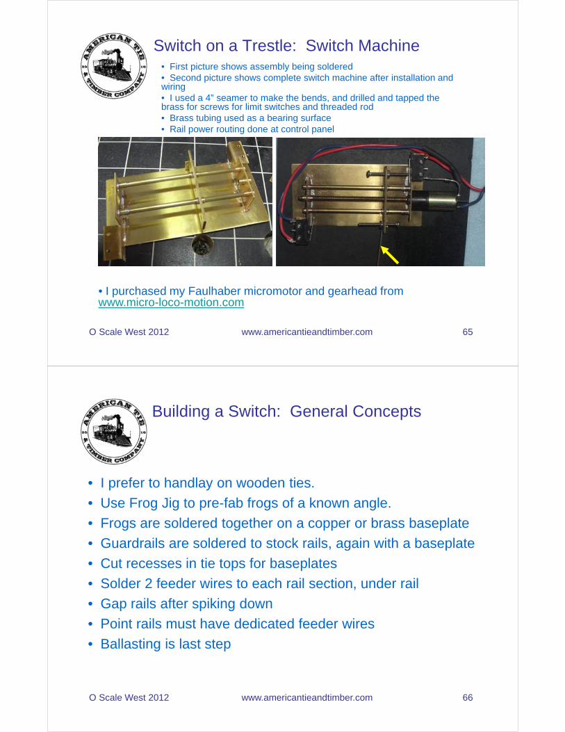
Switch on a Trestle: Switch Machine• First picture shows assembly being soldered• Second picture shows complete switch machine after installation and wiring• I used a 4” seamer to make the bends, and drilled and tapped the brass for screws for limit switches and threaded rod• Brass tubing used as a bearing surface• Rail power routing done at control panel
O Scale West 2012 www.americantieandtimber.com 65
• I purchased my Faulhaber micromotor and gearhead from www.micro-loco-motion.com
• I prefer to handlay on wooden ties.
• Use Frog Jig to pre-fab frogs of a known angle.
• Frogs are soldered together on a copper or brass baseplate
• Guardrails are soldered to stock rails, again with a baseplate
Building a Switch: General Concepts
O Scale West 2012 www.americantieandtimber.com 66
, g p
• Cut recesses in tie tops for baseplates
• Solder 2 feeder wires to each rail section, under rail
• Gap rails after spiking down
• Point rails must have dedicated feeder wires
• Ballasting is last step

http://groups.yahoo.com/group/CCCModOn30/
How to Obtain This Presentation
O Scale West 2012 www.americantieandtimber.com 67
http://groups.yahoo.com/group/CCCModOn30/
• Go to Files section
• Then go to How-To Presentations