Modifying RTR turnouts and scratch- building your...
35
Modifying RTR turnouts and scratch- building your own Nigel Phillips
Transcript of Modifying RTR turnouts and scratch- building your...

Modifying RTR turnouts and scratch-building your own
Nigel Phillips

Turnouts
• These are my personal experiences in modifying HO scale RTR turnouts as well scratch building them. The techniques used are not complicated.
• These are low cost methods, and no expensive tools or jigs are needed.
• Most of us only need 4-5 turnouts of varying types and frog sizes. For a big layout with a large number of identical turnouts it can be cost-effective to buy the frog and point jigs from Fast Tracks (or make your own if you have a CNC mill).
• Turnouts in the real world are known as Switches (NA) or Points (UK). I’ll use “Turnout” for this presentation.
• I don’t make turnouts for a living (advice however is free).
• And of course the usual: Nigel C. Phillips, 2017. Personal use only, no copying any of the contents of this clinic for publication without permission, definitely no commercial use without permission.

Turnouts – Online Resources
• NMRA Resources (nmra.org): RP-12 and RP-13. A lot of information covering the dimensions, many of which are to the 3rd decimal point. Much of the information is being updated and re-organized. Multiscale. Useful in making sure the gap dimensions in a turnout will work.
• Fast Tracks (http://www.handlaidtrack.com/): Downloadable turnout templates to NMRA RPs, plus some great how-to-do-it videos. Jigs for many types of turnouts (expensive), and for filing switch blades and frogs (also expensive). Multiscale.
• Templot (templot.com): Online resource for building exactly what you want (you need a #7.75 frog? No problem). Steep learning curve, a knowledge of the various parts and dimensions of a turnout is required. Multiscale (your very own scale and gauge if you feel like it). UK oriented, but it works just as well for NA track work (HO is covered).
• Peco (http://www.peco-uk.com/page.asp?id=pointplans). Yes, you can build your very own turnout to match Peco dimensions or modify an existing one Multiscale (what Peco sells is there, N through O). Useful for planning the track layout.
• Central Valley Model Works (http://www.cvmw.com/download.htm). HO only, limited number. Instruction manuals. Templates for tangent track (main- and branch-line).
• Proto87 (http://www.proto87.com/CTnCT_designer.html): Easy to use, limited number of turnout types, multiscale.

Turnouts - Materials• Copper clad strip for ties: Clover House (cloverhouse.com). N through O scales.
Turnout copper clad strip – Fast Tracks.
• Scale wood ties: Clover House or Mount Albert (mtalbert.com) for longer lengths.
• Solder: Carrs solder – International Hobbies (interhobmodels.com). Useful range of solders with defined melt temperatures (70°-243°). Carrs also have the appropriate flux for each type. I use 145° (ties) and 186° (frogs) solder. Wear disposable gloves and have adequate ventilation when soldering.
• Tinned 22 gage copper wire for connections – RadioShack.
• Flux: Organic, low residue (Kester, DCC Concepts or similar) or zinc/phosphoric acid (needs rinsing). I do not recommend rosin-core solders.
• Rail: One or two turnouts – buy some flexitrack. Otherwise Micro Engineering (microengineering.com) or most major suppliers. Try ebay or train shows for used turnouts and track.
• Multimeter (essential for copper-clad work)

Turnouts – Basic Tools
• Soldering iron: A temperature controlled soldering iron (preferably with feedback) with a fine tip (a large chisel tip helps when soldering frogs).
• Rail clippers (Xuron or similar), heavy duty box-cutter, smooth faced pliers, mill file and needle files.
• Dremel or similar with right-angle head attachment (or a fret saw with metal-cutting blades).
• Fine cut-off discs and grinding wheels for the Dremel.
• HB-4B pencil for marking soldering limits (the 4% wax content stops solder adhering, the graphite makes it visible).

Turnouts – Basic Tools for Modifying RTR Turnouts

Turnouts –Tools for Scratch Building
• Soldering jig for ties (top LHS). Useful.
• Test trucks – regular and semi-fine scale wheels (middle LHS). Necessary.
• Steel weight (Top RHS). Useful.
• Track and gap gauges (roller and triangular) and back-to-back gauge (middle). Necessary.
• Rail bender (middle RHS). Useful.

Turnouts – Naming of Parts
Guard railWing railFrog (- - -)
Closure rails
Heel
Stock rails
Point rails (blades)
Points

Turnouts – Modifying a Peco Code 83 #6
• Peco turnouts
– As supplied, they are power routed (like many other turnouts).
– The point gauge is 13.92mm. NMRA S-3.2 calls for 14.94mm (+ 0.05mm, -0.01mm).
– The point rails are cut pressed metal (essentially bridge rail).
– Electrical continuity depends on the point -stock rail contact.
– Continuity between the point rails and closure rails depends on a rotating disc contact.
– The frog is 8” long (203mm) and needs insulating rail joiners on the inner stock exit rails.

Turnouts – Power Routing IssuesInsulated joiners required here
Wide point-stock rail gap used hereto prevent shorting by wheels with stock rail of opposite polarity
Frog exit rails, frog, closure rails and points have the same polarity as the stock rail. Electrical continuity is dependent on point contact and point rail-closure rail contact

Turnouts – Modifying a Peco Code 83 #6
Shorten frog to around 2” and isolate from rest of track
Remove existing point rail-closure rail contacts. Add new copper-clad ties. Make new hinge from code 100 rail joiner
Remove existing tie bar, replace with copper-clad. Adjust point gauge to NMRA standard or close to.
Make new point rails.
Add wiring to the frog and rails to ensure continuity and eliminate isolating rail joiners

Making Points – Some Notes
• The foot of the stock rail is removed where the points are located.• The outside face of the point rails (head and foot) is beveled with an
additional short bevel at the top so that it sits snugly against the stock rail.• Removing a small amount of metal from the inside edge of the stock rail
will also ensure a tighter fit (only a few thou’! Peco do this). Putting a small “jog” in the rail will also work (difficult with code 100 rail).
• The inside edge of the point rail head is also beveled at an angle so that the wheels ride up and onto the point.
• Putting a slight “set” in the points so that they sit flat against the stock rails will also ensure a tight fit (especially with the curved point rail).
• This can all be done with a mill file, an electric sander (belt or circular face) or a jig.
• The Mk-1 eyeball works well in judging the bevels and angles.• Practice makes perfect, or at least it makes points that work. Check out
the Fast Tracks videos to see the above being done. Or have a look at some 12” to the foot points to see what the big boys do.
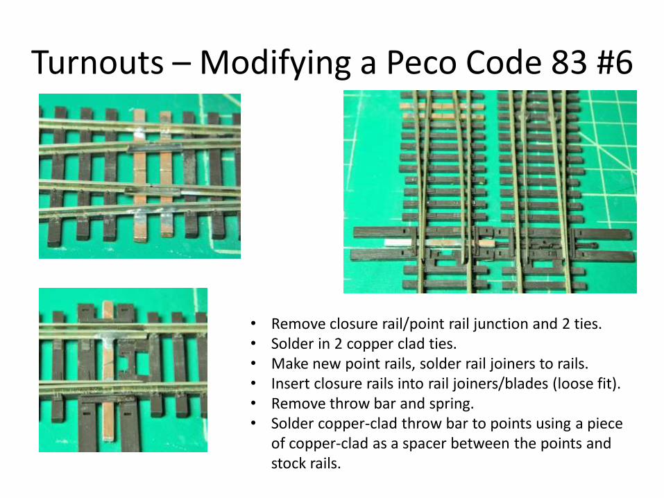
Turnouts – Modifying a Peco Code 83 #6
• Remove closure rail/point rail junction and 2 ties.• Solder in 2 copper clad ties.• Make new point rails, solder rail joiners to rails.• Insert closure rails into rail joiners/blades (loose fit).• Remove throw bar and spring.• Solder copper-clad throw bar to points using a piece
of copper-clad as a spacer between the points and stock rails.

Turnouts – Modifying a Peco Code 83 #6
A. Add jumper wires to stock rails using 22 gauge tinned copper wire.B. Isolate frog by cutting through closure rails and frog heel rails (to give a 2” long frog).C. Add frog power wire (if missing, often the case).D. Add jumper wires from stock rails to closure rails (TBD when adding bus jumper wires)E. Add jumper wires from stock rails to point rails via bottom of rail joiner.
This gives wired, live points and closure rails (both sides), an isolated and live frog, live exit rails of the correct polarity, and no need for insulated rail joiners
A B C B D E

Turnouts – Modifying a Peco Code 83 #6
Finally, reinstall the throw bar spring cover.
It is possible to refit the spring by modification of the throw bar if using solenoid switch motors, but this is not necessary if using stall motors or sprung ground throws.
You can also reuse the Pecothrow bar by soldering brass tabs to the bottom of the points.
The plastic throw ties can be replaced with copper-clad ones if desired.

Turnouts – Shinohara Code 100 #6
Out of the box, unused, straight from the auction site (NOS).
Power routing with a vengeance!
Electrical continuity depends on point contact with the stock rail.
Very weak spring mechanism under the bottom pivot bar making the above problematic.
Ingenious point arrangement with double pivots (both loose) on the point rails.
Rotation at the heel is through rail joiners.

Turnouts – Shinohara Code 100 #6
Shinohara code 100 issues:
• Power routed with problematic point contact.• Extremely long frog exit rails.• Wide point rail-stock rail gaps.

Turnouts – Shinohara Code 100 #6
• Modifications– Isolate frog
– Add jumper wires before (closure rails) and after (stock rails) frog
– Wire isolated frog
– Remove old point rails and pivot mechanisms
– Shorten closure rails
– Fabricate longer point rails
– Make pivots between closure rails and point rails using rail joiners
– Add jumper wires to connect closure rails and point rails

Turnouts –Shinohara Code 100 #6
Hinged closure rail-point rail heel using Shinohara rail connectors
Open joiner slightly after soldering to point rail to allow lateral movement.

Turnouts – Modifying a Shinohara Code 100 #6 to DCC Standards
Jumper wires – exit stock rails after isolating the frog. Shinohara conveniently provide slots in the ties for these wires on later models. Early ones will need slots cutting.
Jumper wires – stock rails to closure rails and closure to point rails (braided wire soldered to bottom of rail connector on point rail). Slots need to be cut in the ties for these.

Turnouts – Shinohara Code 100 #6
Throw bars. One or two, or even four? This is 156lb heavy-duty rail in 12” to the foot!

Crossover from 2 Shinohara Code 100 Turnouts
• Connecting 2 LH or RH turnouts to make a crossover requires rail joiners, and will normally mean track centers greater than 2”.
• Using the outside stock rail on the exit road of each turnout will allow a joiner-free connection.
• 2 turnouts are often less expensive than a RTR crossover (especially used ones!). This one cost $15 for the 2 #6 LH turnouts, and another $3 in copper-clad and solder. Retail is around $35.
• This conversion goes a stage further than the previous ones, rail gauges are essential.

Crossover from 2 Shinohara Code 100 Turnouts
Rail to be removed from top turnout shown in red, opposite sides for bottom turnout. 2” track centers. Frog isolation cuts already made, new point rails and hinges, replacement throw bars soldered up, and wiring completed to DCC standards as before.
Tie and rail template drawn up in CorelDraw (can be done in MS PowerPoint or Word), 2” track centers.

Crossover from 2 Shinohara Code 100 Turnouts
Above: Rails soldered to copper-clad ties using the template. No rail connectors are used between the 2 turnouts. All copper-clad ties gapped where necessary.
Below: Completed crossover with copper-clad ties painted up in matt black.

#6 Wye, Code 100 rail
• This project goes one step further than the crossover, and is 100% scratch built.
• A wye is probably the simplest turnout to build.• A downloadable (free) turnout template from Fast Tracks is
used (there are others).• Track gauges are required.• A jig is required for the frog – buy one from Fast Tracks
($$$) or make your own from wood or copper-clad (¢¢¢).• Rather than using a mix of copper-clad and timber ties, an
all copper-clad construction is described.• The cost of the wye is around $4.00 (copper-clad ties, rail,
solder, flux, paint).

#6 Wye, Code 100 rail
• Frog jig – low cost version– A #6 frog has an angle of 9.53°– There are 2 components to the jig:
• One for making the bevel on each rail (1/2 the frog angle: 4.765°)• One for soldering the frog (9.53°).
– Make templates on paper using CorelDraw or similar, or use an accurate protractor (9.5°is accurate enough). Simple trigonometry will work as well (sum of the angles of a triangle = 180°).
– Transfer templates to a block of wood, glue wood strips to required angles.
– Use a Dremel or similar with a grinding stone to bevel rail ends at 4.765°.

#6 Wye, Code 100 rail
Wood track ties glued to a block of wood using printed templates.
Top. Rail bevel jig. The rail is held between the wood, the bevel is made along the edge using the Dremel and grinding stone. The second piece of rail is treated the same but upside down. The edge of the block is used as a straight edge for the Dremel head.
Bottom: Frog soldering jig. The 2 pieces of rail are placed in the jig, beveled edges inside and together, held in place with the weight, and soldered up using 186° solder.
Low cost frog point bevel and soldering jig*
*This is as cheap as it gets. It’s surprisingly accurate for such a low tech approach, around ± 2.5% (±0.23°). Accurate enough in the 1:87 world. I batch-build 10 frogs at a time.

#6 Wye, Code 100 rail
Printed template with copper-clad ties held in place with double sided tape and soldered to the rails. The frog (far left) is soldered in place first, then the stock rails followed by the point rails. Rail jigs and trucks are used to make sure the positions are correct.
186° solder for the frog and 145° solder for the ties. This minimizes the risk of melting the assembled frog when soldering up to the ties or when wiring.

#6 Wye, Code 100 rail
Wing rail and guard rail bends are made by nicking the foot of the rail with the Xurons and bending the rail with smooth-faced pliers.
Note the filed bevel on the inside edge of the wing rails.

#6 Wye, Code 100 RailWorking with copper-clad means a bit more care with the jumper wiring, as there are no insulated plastic ties.
Here the connections between the stock exit rails have been insulated with heat-shrink where they cross the opposite polarity stock rails. The frog wire is also insulated.
This is not necessary on the stock/closure rail and stock/point rail jumpers.

#6 Wye, Code 100 Rail
Completed wye painted with matt black. The insulating gaps in the copper-clad ties can be filled with epoxy or modeling putty if desired. Note insulated wiring.

45° degree Crossing
• Required: Single line crossing double tracks at 45° in code 100.
• Fast Tracks template, 2 of, joined together at 2” track centers. Adjust tie spacing to suit.
• Jigs made for 45° and 135° angles, 22.5° and 67.5° bevels.
• 16 x 135° and 16 x 45° angles required.

45° degree Crossing
Jig
Template

45° degree Crossing
Soldered-up Painted matt black
I was happy, stock trundles through it quite nicely. Wiring this for DCC would be interesting. Turns out I really need a 30°, not a 45° crossing. Derelict track cameo perhaps?

Conclusions
• Modifying RTR turnouts is quick and easy.• New life can be given to those old “clunkers” or questionable
designs by replacing point rails, getting rid of power-routing, and rewiring. Not covered in this clinic, but replacing those “dead” plastic frogs with metal ones is an easy upgrade.
• Building turnouts from scratch is not complicated, and can be done with inexpensive tools and equipment that most of us have.
• Commercial jigs are available for frogs and points if a large number of turnouts are required (or you have deep pockets). Otherwise make your own.
• It can be very cost-effective, a scratch built turnout to NMRA standards or better that is DCC compliant costs between $4-$8 depending on the source of rail.
• One length of flex track gives 6 feet of rail, more than enough for a #6 or #8 turnout.