nxp/c frequency converters user's manual · vacon nxc user’s manual index 1 safety 2 introduction...
103
nxp/c frequency converters user's manual
Transcript of nxp/c frequency converters user's manual · vacon nxc user’s manual index 1 safety 2 introduction...

nxp/c frequency converters
user's manual

vacon • 1
24-hour support: +358 (0)40 837 1150 • Email: [email protected]
AT LEAST THE FOLLOWING STEPS OF THE START-UP QUICK GUIDE MUST BE PERFORMED DURINGTHE INSTALLATION AND COMMISSIONING.
IF ANY PROBLEMS OCCUR, PLEASE CONTACT YOUR LOCAL DISTRIBUTOR.
Start-up Quick Guide
1. Check that the delivery corresponds to your order, see Chapter 3.
2. Before taking any commissioning actions read carefully the safety instructions in Chapter 1.
3. Before the mechanical installation, check the minimum clearances around the unit(Chapter 5.6) and check the ambient conditions in Chapter 4.2.
4. Check the size of the motor cable, mains cable, mains fuses and check the cableconnections, read Chapters 6.2.2 to 6.2.7.
5. Follow the installation instructions, see Chapter 7.
6. Control connections are explained in Chapter 8.2.1.
7. If the Start-Up wizard is active, select the language of the keypad, the application youwant to use and set the basic parameters asked by the wizard. Always confirm by press-ing the Enter button. If the Start-Up wizard is not active, follow the instructions 7a and 7b.
7a. Select the language of the keypad from the Menu M6, page 6.1. Instructions on using thekeypad are given in Chapter 9.
7b. Select the application you want to use from the Menu M6, page 6.2. Instructions on usingthe keypad are given in Chapter 9.
8. All parameters have factory default values. In order to ensure proper operation, checkthe rating plate data for the values below and the corresponding parameters ofparameter group G2.1.
nominal voltage of the motornominal frequency of the motornominal speed of the motornominal current of the motormotor cos
Some options may require special parameter settings
All parameters are explained in the All in One Application Manual.
9. Follow the commissioning instructions, see Chapter 10.
10. The Vacon NX_ Frequency Converter is now ready for use.
Vacon Plc is not responsible for the use of the frequency converters againstthe instructions.

2 • vacon
Tel. +358 (0)201 2121 • Fax +358 (0)201 212 205
CONTENTS
VACON NXC USER’S MANUAL
INDEX
1 SAFETY
2 INTRODUCTION
3 RECEIPT OF DELIVERY
4 TECHNICAL DATA
5 MOUNTING
6 CABLING AND CONNECTIONS
7 LOW HARMONIC REGENERATIVE CABINET DRIVE
8 INSTALLATION INSTRUCTIONS
9 CONTROL KEYPAD
10 COMMISSIONING
11 FAULT TRACING

vacon • 3
24-hour support: +358 (0)40 837 1150 • Email: [email protected]
INDEX Document code: ud01011d.doc
Date: 7.12.2009
1. SAFETY ............................................................................................................................................ 5 1.1 Warnings .......................................................................................................................................... 5 1.2 Safety instructions ........................................................................................................................... 5 1.3 Earthing and earth fault protection ................................................................................................ 6 1.4 Running the motor ........................................................................................................................... 6
2. INTRODUCTION ............................................................................................................................... 7 2.1 Manufacturer's declaration of conformity ...................................................................................... 8
3. RECEIPT OF DELIVERY .................................................................................................................... 9 3.1 Type designation code ..................................................................................................................... 9
3.1.1 NX type designation ..................................................................................................................... 9 3.2 NXC additional option codes ......................................................................................................... 10
3.2.1 Cabling (C-group) ...................................................................................................................... 10 3.2.2 External Terminals (T-group) ................................................................................................... 10 3.2.3 Input Device (I-group) ................................................................................................................ 10 3.2.4 Main Circuit (M-group) .............................................................................................................. 10 3.2.5 Output Filters (O-group) ............................................................................................................ 10 3.2.6 Protection Devices (P-group) .................................................................................................... 10 3.2.7 General (G-group) ...................................................................................................................... 10 3.2.8 Auxiliary Equipment (A-group) .................................................................................................. 11 3.2.9 Door Mounted (D-group) ........................................................................................................... 11
3.3 Storage ........................................................................................................................................... 12 3.4 Maintenance .................................................................................................................................. 12 3.5 Warranty ........................................................................................................................................ 13
4. TECHNICAL DATA ........................................................................................................................... 14 4.1 Power ratings ................................................................................................................................ 14
4.1.1 Vacon NXP/C – Mains voltage 380—500 V ............................................................................... 14 4.1.2 Vacon NXC Regenerative low harmonic drives – Mains voltage 380—500 V .......................... 15 4.1.3 Vacon NXP/C 6 – Mains voltage 500—690 V ............................................................................. 16 4.1.4 Vacon NXC Regenerative low harmonic drives – Mains voltage 525—690 V .......................... 17
4.2 Technical data ................................................................................................................................ 18
5. MOUNTING ..................................................................................................................................... 20 5.1 Dimensions .................................................................................................................................... 20 5.2 Lifting the unit out of the transport packaging ............................................................................. 22 5.3 Fixing the unit to the floor or to the wall ...................................................................................... 22
5.3.1 Fixing to the floor and to the wall ............................................................................................. 23 5.3.2 Fixing to the floor only ............................................................................................................... 23
5.4 AC choke connections ................................................................................................................... 24 5.5 Auxiliary voltage transformer tappings ........................................................................................ 25 5.6 Cooling ........................................................................................................................................... 26
5.6.1 Free space around the cabinet ................................................................................................. 26 5.7 Power losses .................................................................................................................................. 28
6. CABLING AND CONNECTIONS ........................................................................................................ 29 6.1 Understanding the power unit topology ....................................................................................... 29 6.2 Power connections ........................................................................................................................ 31
6.2.1 LCL filter wiring diagram of NXC regenerative low-harmonic drive ....................................... 31
4 • vacon
Tel. +358 (0)201 2121 • Fax +358 (0)201 212 205
6.2.2 Mains and motor cables.............................................................................................................. 336.2.3 Thermal supervision of option +ODU ......................................................................................... 426.2.4 DC supply and brake resistor cables ......................................................................................... 426.2.5 Control cable ............................................................................................................................... 426.2.6 Cable and fuse sizes, 380-500V units ........................................................................................ 436.2.7 Cable and fuse sizes, 500/525-690V units ................................................................................. 46
7. LOW HARMONIC REGENERATIVE CABINET DRIVE .........................................................................497.1 NXC Low-Harmonic Regenerative Cabinet Pre-Charging and MCCB Operating Instructions .. 49
7.1.1 Manual operation (MAN) ............................................................................................................. 497.1.2 Remote operation (REM) ............................................................................................................. 507.1.3 Automatic operation (AUTO) ....................................................................................................... 517.1.4 Circuit-Breaker TRIP due to overload or short-circuit ............................................................ 51
8. INSTALLATION INSTRUCTIONS ......................................................................................................538.1 Cable installation and the UL standards ....................................................................................... 54
8.1.1 Cable and motor insulation checks ........................................................................................... 558.2 Control unit ...................................................................................................................................... 56
8.2.1 Control connections .................................................................................................................... 578.2.2 Control terminal signals ............................................................................................................. 59
8.3 Connecting power supply and internal control cables ................................................................. 638.4 Optic fibre cables, signal listing and connections ......................................................................... 64
9. CONTROL KEYPAD .........................................................................................................................659.1 Indications on the Keypad display .................................................................................................. 65
9.1.1 Drive status indications .............................................................................................................. 659.1.2 Control place indications ............................................................................................................ 669.1.3 Status LEDs (green – green – red) ............................................................................................. 669.1.4 Text lines ...................................................................................................................................... 66
9.2 Keypad push-buttons ...................................................................................................................... 679.2.1 Button descriptions ..................................................................................................................... 67
9.3 Navigation on the control keypad ................................................................................................... 689.3.1 Monitoring menu (M1) ................................................................................................................. 709.3.2 Parameter menu (M2) ................................................................................................................. 719.3.3 Keypad control menu (M3) .......................................................................................................... 739.3.4 Active faults menu (M4) .............................................................................................................. 759.3.5 Fault history menu (M5) .............................................................................................................. 779.3.6 System menu (M6) ....................................................................................................................... 789.3.7 Expander board menu (M7) ........................................................................................................ 93
9.4 Further keypad functions ................................................................................................................ 93
10. COMMISSIONING ............................................................................................................................9410.1 Safety ................................................................................................................................................ 9410.2 Commissioning of the frequency converter .................................................................................. 94
11. FAULT TRACING .............................................................................................................................9711.1 Fault time data record .................................................................................................................... 9711.2 Fault codes ....................................................................................................................................... 98

SAFETY vacon • 5
24-hour support: +358 (0)40 837 1150 • Email: [email protected] 1
1. SAFETY
1.1 Warnings
1 The Vacon NX frequency converter is meant for fixed installations only.
2 Do not perform any measurements when the frequency converter isconnected to the mains.
3 Do not perform any voltage withstand tests on any part of Vacon NX.There is a certain procedure according to which the tests shall be per-formed. Ignoring this procedure may result in damaged product.
4 The frequency converter has a large capacitive leakage current.
5 If the frequency converter is used as a part of a machine, the machinemanufacturer is responsible for providing the machine with a mainswitch (EN 60204-1).
6 Only spare parts delivered by Vacon can be used.
7 The motor starts at power-up if the start command is 'ON'. Furthermore,the I/O functionalities (including start inputs) may change if parameters,applications or software are changed. Disconnect, therefore, the motor ifan unexpected start can cause danger.
8 Prior to measurements on the motor or the motor cable, disconnect themotor cables from the frequency converter.
9 Do not touch the components on the circuit boards. Static voltage dis-charge may damage the components.
1.2 Safety instructions
1 The components of the power unit of the frequency converter and allcabinet mounted devices are potentially live when Vacon NX is connectedto mains potential. Coming into contact with this voltage is extremelydangerous and may cause death or severe injury.
2 The motor terminals U, V, W and the DC-link/brake resistor terminals –/+and all other mains devices are potentially live when Vacon NX is con-nected to mains, even if the motor is not running.
3 After disconnecting the frequency converter from the mains, wait untilthe fan stops and the indicators on the keypad go out (if no keypad isattached see the indicators on the cover). Wait 5 more minutes beforedoing any work on Vacon NX connections. Do not even open the cabinetdoor before this time has expired.
4 The control I/O-terminals are isolated from the mains potential. How-ever, the relay outputs and other I/O-terminals may have a dangerouscontrol voltage present even when Vacon NX is disconnected from mains.
5 Before connecting the frequency converter to mains make sure that theVacon NX front and cable covers as well as the cabinet doors are closed.
ONLY A COMPETENT ELECTRICIAN MAY CARRY OUTTHE ELECTRICAL INSTALLATION

6 • vacon SAFETY
Tel. +358 (0)201 2121 • Fax +358 (0)201 212 2051
1.3 Earthing and earth fault protection
The Vacon NX frequency converter must always be earthed with an earthing conductor connected to the PEbar in the lower front side of the cabinet.
The earth fault protection inside the frequency converter protects only the converter itself against earthfaults in the motor or the motor cable. It is not intended for personal safety.
Due to the high capacitive currents present in the frequency converter, fault current protective switchesmay not function properly.
1.4 Running the motor
Warning symbolsFor your own safety, please pay special attention to the instructions marked with the following symbols:
= Dangerous voltage
= General warning
= Hot surface – Risk of burn
MOTOR RUN CHECK LIST
1 Before starting the motor, check that the motor is mounted properly andensure that the machine connected to the motor allows the motor to bestarted.
2 Set the maximum motor speed (frequency) according to the motor andthe machine connected to it.
3 Before reversing the motor make sure that this can be done safely.
4 Make sure that no power correction capacitors are connected to themotor cable.
5 Make sure that the motor terminals are not connected to mainspotential.

INTRODUCTION vacon • 7
24-hour support: +358 (0)40 837 1150 • Email: [email protected] 2
2. INTRODUCTION
The Vacon NXC is a product range of free standing enclosed frequency converters for the high powerrange. The NXC is a modular product intended for use in all applications where reliability and highavailability is appreciated.
This manual gives the basic information required to successfully perform installation and basiccommissioning. Due to the high amount of options available, not all possible variations are describedin this manual. For more information, refer to delivery-specific documentation. This manual as-sumes good competence in installation and commissioning skills.
In the All in One Application Manual you will find information about the different applications in-cluded in the All in One Application Package. Should these applications not meet the requirementsof your process please contact the manufacturer for information on special applications.
Information on the installation of the drive in a cabinet can be found in manuals 'NXP FrequencyConverters, IP00 Module Installation, Frames FR10 to FR14 (ud00908) as well as Frequency Inverter(UD01063) and Active Front End (UD01190) manuals.
This manual is available in both paper and electronic editions. We recommend you to use the elec-tronic version if possible. If you have the electronic version at your disposal you will be able tobenefit from the following features:
The manual contains several links and cross-references to other locations in the manual whichmakes it easier for the reader to move around in the manual, to check and find things faster.
The manual also contains hyperlinks to web pages. To visit these web pages through the links youmust have an internet browser installed on your computer.
In case you are in doubt about your ability to perform installation or commissioning,do not proceed. Contact your local Vacon partner for advice.
For the NXC regenerative low-harmonic drive also see the AFE application manual.

8 • vacon INTRODUCTION
Tel. +358 (0)201 2121 • Fax +358 (0)201 212 2053
2.1 Manufacturer's declaration of conformity
Below you can find the Manufacturer's Declarations of Conformity assuring the compliance of VaconNXP/C frequency converters with the EMC-directives.
EU DECLARATION OF CONFORMITY
We
Manufacturer's name: Vacon Oyj
Manufacturer's address: P.O.Box 25Runsorintie 7FIN-65381 VaasaFinland
hereby declare that the product
Product name: Vacon NXP/C Frequency converter
Model designation: Vacon NXP/C 0261 5…. to 2700 5….Vacon NXP/C 0125 6…. to 2250 6….
has been designed and manufactured in accordance with the following standards:
Safety: FR9, FR10, FR12: EN60204-1 (2009) (as relevant)
FR11, FR13/14: EN61800-5-1 (2007)
EMC: EN61800-3 (2004),
and conforms to the relevant safety provisions of the Low Voltage Directive(2006/95/EC) as amended by the Directive (93/68/EEC) and EMC Directive2004/108/EC.
It is ensured through internal measures and quality control that the product conformsat all times to the requirements of the current Directive and the relevant standards.
In Vaasa, 24th of September, 2009Vesa LaisiPresident
The year the CE marking was affixed: 2002

RECEIPT OF DELIVERY vacon • 9
24-hour support: +358 (0)40 837 1150 • Email: [email protected] 3
3. RECEIPT OF DELIVERY
Vacon NX frequency converters have undergone scrupulous tests and quality checks at the factorybefore they are delivered to the customer. However, after unpacking the product, check that nosigns of transport damages are to be found on the product and that the delivery is complete (com-pare the type designation of the product to the code below).
Should the drive have been damaged during the shipping, please contact primarily the cargo insur-ance company or the carrier.
If the delivery does not correspond to your order, contact the supplier immediately.
In the small plastic bag included in the delivery you will find a silver Drive modified sticker. Thepurpose of the sticker is to notify the service personnel about the modifications made in the fre-quency converter. Attach the sticker to the equipment to avoid losing it. Should the frequency con-verter be later modified (option board added, IP or EMC protection level changed), mark the changein the sticker.
3.1 Type designation code
3.1.1 NX type designation
NXC 0000 A 2 L 0 SSG A1A20000C3 +I FD5
nk3_2.fh11Product range: NXC = cabinet
Nominal current (low overload)e.g. 0460 = 460A etc.
Nominal mains voltage (3-phase):5 = 380–500Vac, 6 = 525–690Vac
Enclosure class:2 = IP21/Nema 1 (cabinet-mounted),5 = IP54/Nema 12 (cabinet-mounted)
Control keypad:A = standard (alpha-numeric)B = no local control keypadF = dummy keypadG = graphic display
EMC emission level EN61800-3:L = 2nd environmentT = For IT networks
Brake chopper0 = No brake chopper, 1 = Integrated brake chopper
ControlF = standard FR9 and NXCN = standard IP00 FR10 and NXC with IP54 control unit enclosureG = as F but varnished boardsO = as N but varnished boards
CoolingS = standard air-cooled
SupplyS = 6-pulseT = 12-pulseR = Regenerative low-harmonic (AFE)
Option boards; each slot is represented by two characters where:Ax = basic I/O board, Bx = expander I/O board,Cx = fieldbus board, Dx = special board
NXC options
Figure 3-1. Vacon NXC type designation code

10 • vacon RECEIPT OF DELIVERY
Tel. +358 (0)201 2121 • Fax +358 (0)201 212 2053
3.2 NXC additional option codes
The NXC enclosure solution contains additional pre-engineered hardware options. These options areappended to the basic type code by using “+” codes. You will find the complete type code on thename plate of the unit. The most common NXC options are listed below:
3.2.1 Cabling (C-group)
+CIT Input (mains) cabling from TOP+COT Output motor cabling from TOP
3.2.2 External Terminals (T-group)
+TIO I/O+ aux terminals (35pcs) X2+TID I/O+ double aux terminals (70pcs) Double-decker terminals X2+TUP Separate terminals for 230VAC CV X1
3.2.3 Input Device (I-group)
+ILS Load switch+IFD Fused disconnecting switch With aR Fuses+ICO Contactor+IFU Fused With aR Fuses+ICB Moulded-case circuit breaker
3.2.4 Main Circuit (M-group)
+MDC DC-bus bar connection Req. BSF converter hardware
3.2.5 Output Filters (O-group)
+OCM Common mode choke Ferrite rings 2x6+ODU dU/dt+OSI Sine
3.2.6 Protection Devices (P-group)
+PTR Thermistor relay PTB certified+PES Em. stop (cat 0) DI3+PED Em. stop (cat 1) DI6 (sys.appl.)+PAP Arc protection+PIF Insulation fault sensor For IT-networks
3.2.7 General (G-group)
+G40 400 empty cabinet+G60 600 empty cabinet+G80 800 empty cabinet+GPL 100mm base/plinth For 400mm, 600mm or 800mm+GPH 200mm base/plinth For 400mm, 600mm or 800mm

RECEIPT OF DELIVERY vacon • 11
24-hour support: +358 (0)40 837 1150 • Email: [email protected] 3
3.2.8 Auxiliary Equipment (A-group)
+AMF Motor fan control+AMH Motor heater feeder+AMB Mechanical brake control+ACH Cabinet heater+ACL Cabinet light+ACR Control relay+AAI Analogue signal isolator AI1, AO1, AI2+AAC Aux. contact (input device) Wired to DI3+AAA Aux. contact (control voltage devices) Chained to DI3+ATx Aux. Transformer 400-690/230VAC x=1 (200VA)
x=2 (750VA)x=3 (2500VA)x=4 (4000VA)
+ADC Power supply 24VDC 10A+ACS 230VAC customer socket With 30mA leak current prot.
3.2.9 Door Mounted (D-group)
+DLV Pilot light (Control voltage on) 230VAC+DLD Pilot light (DO1) 24VDC, DO1+DLF Pilot light (FLT) 230VAC, RO2+DLR Pilot light (RUN) 230VAC, RO1+DAR Potentiometer for reference AI1+DCO MC operation switch 0-1-START+DRO Local / Remote op. switch Loc/Rem wired to DI6+DEP Emergency stop push-button+DRP Reset push-button DI6+DAM Analogue meter (AO1) 48mm, std scale 0-100%+DCM Analogue meter + current transformer 48mm, std scale 0-600A+DVM Analogue vltg meter with sel.switch 0, L1-L2, L2-L3, L3-L1

12 • vacon RECEIPT OF DELIVERY
Tel. +358 (0)201 2121 • Fax +358 (0)201 212 2053
3.3 Storage
If the frequency converter is to be kept in store before use make sure that the ambient conditionsare acceptable:
Storing temperature –40…+70 CRelative humidity <95%, no condensation
The environment should also be free from dust. If there is dust in the air the converter should bewell protected to make sure dust does not get into the converter.
If the converter is to be stored during longer periods the power should be connected to the converteronce in 24 months and kept on for at least 2 hours. If the storage time exceeds 24 months theelectrolytic DC capacitors need to be charged with caution. Therefore, such a long storage time isnot recommended.
If the storing time is much longer than 24 months, the recharging of the capacitors has to be carriedout so that the possible high leakage current through the capacitors is limited. The best alternativeis to use a DC-power supply with adjustable current limit. The current limit has to be set for exampleto 300…500mA and the DC-power supply has to be connected to the B+/B- terminals (DC supplyterminals).
DC-voltage must be adjusted to nominal DC-voltage level of the unit (1.35*Un AC) and supplied atleast for 1 hour.
If DC-voltage is not available and the unit has been stored de-energized much longer than 1 yearconsult factory before connecting power.
3.4 Maintenance
In normal conditions, Vacon NX frequency converters are maintenance-free. However, werecommend to keep the converter clean, e.g. by cleaning the heatsink with compressed airwhenever necessary.
In IP54 units, the air filters in the door and in the roof should be cleaned or replaced regularly.
We also recommended to follow proactive maintenance schedule to ensure the highest possibleutilization rate of the cabinet drive.
Maintenance interval Maintenance action12 months (if unit stored) Reform capacitors (see separate instruction)
6-24 months(depending on environment)
Check I/O terminalsCheck tightness of mains connectionClean cooling tunnelCheck operation of cooling fan, check for cor-rosion on terminals, busbars and other surfacesCheck door and roof filters
5-7 years Change cooling fans:- main fan- fan of the LCL filter
5-10 years Change DC bus capacitors if DC voltage rippleis high
Table 3-1. Proactive maintenance schedule

RECEIPT OF DELIVERY vacon • 13
24-hour support: +358 (0)40 837 1150 • Email: [email protected] 3
3.5 Warranty
Only manufacturing defects are covered by the warranty. The manufacturer assumes noresponsibility for damages caused during or resulting from transport, receipt of the delivery,installation, commissioning or use.
The manufacturer shall in no event and under no circumstances be held responsible for damagesand failures resulting from misuse, wrong installation, unacceptable ambient temperature, dust,corrosive substances or operation outside the rated specifications.
Neither can the manufacturer be held responsible for consequential damages.
The Manufacturer's time of warranty is 18 months from the delivery or 12 months from thecommissioning whichever expires first (Vacon Warranty Terms).
The local distributor may grant a warranty time different from the above. This warranty time shall bespecified in the distributor's sales and warranty terms. Vacon assumes no responsibility for anyother warranties than that granted by Vacon itself.
In all matters concerning the warranty, please contact first your distributor.

14 • vacon TECHNICAL DATA
Tel. +358 (0)201 2121 • Fax +358 (0)201 212 2054
4. TECHNICAL DATA
4.1 Power ratings
4.1.1 Vacon NXP/C – Mains voltage 380—500 V
High overload = Max current IS, 2 sec/20 sec, Rated overload current, 1 min/10 minFollowing continuous operation at rated output current, rated overload currentfor 1 min, followed by a period of load current less than rated current, and ofsuch duration that the r.m.s output current, over the duty cycle, does not exceedrated output current (IH)
Low overload = Max current IS, 2 sec/20 sec, Rated overload current, 1 min/10 minFollowing continuous operation at rated output current, rated overload currentfor 1 min, followed by a period of load current less than rated current, and ofsuch duration that the r.m.s output current, over the duty cycle, does not exceedrated output current (IL)
Mains voltage 380-500 V, 50/60 Hz, 3~Frequencyconvertertype
Loadability Motor shaft power
FrameDimensions and
weight*WxHxD/kg
Low High 400V supply 500V supplyRatedcontin.
current IL
(A)
Ratedoverloadcurrent
(A)
Ratedcontin.
current IH
(A)
Ratedoverloadcurrent
(A)
Maxcurrent
IS
Lowoverload
P(kW)
Highoverload
P(kW)
Lowoverload
P(kW)
Highoverload
P(kW)
NX_0261 5 261 287 205 308 349 132 110 160 132 FR9 606x2275x605/371NX_0300 5 300 330 245 368 444 160 132 200 160 FR9 606x2275x605/371NX_0385 5 385 424 300 450 540 200 160 250 200 FR10 606x2275x605/371NX_0460 5 460 506 385 578 693 250 200 315 250 FR10 606x2275x605/403NX_0520 5 520 572 460 690 828 250 250 355 315 FR10 606x2275x605/403NX_0590 5 590 649 520 780 936 315 250 400 355 FR11 806x2275x605/577NX_0650 5 650 715 590 885 1062 355 315 450 400 FR11 806x2275x605/577NX_0730 5 730 803 650 975 1170 400 355 500 450 FR11 806x2275x605/577NX_0820 5 820 902 730 1095 1314 450 400 560 500 FR12 1206x2275x605/810NX_0920 5 920 1012 820 1230 1476 500 450 630 560 FR12 1206x2275x605/810NX_1030 5 1030 1133 920 1380 1656 560 500 710 630 FR12 1206x2275x605/810NX_1150 5 1150 1265 1030 1545 1620 630 560 800 710 FR13 1406X2275X605/1000NX_1300 5 1300 1430 1150 1725 2079 710 630 900 800 FR13 1806X2275X605/1100NX_1450 5 1450 1595 1300 1950 2484 800 710 1000 900 FR13 1806X2275X605/1100NX_1770 5 1770 1947 1600 2400 2880 1000 900 1200 1100 FR14 2806X2275X605/2440NX_2150 5 2150 2365 1940 2910 3492 1200 1100 1500 1300 FR14 2806X2275X605/2500
Table 4-1. Power ratings and dimensions of Vacon NX 6- and 12-pulse drives supply voltage 380—500V.
Note: The rated currents in given ambient temperatures are achieved only when the switching fre-quency is equal to or less than the factory default (automatic thermal management).
*The dimensions indicated are for the basic 6-pulse IP21 version of the converter cabinet. Some op-tions may increase the width, height or weight of the cabinet. See the delivery-specific documenta-tion for more details.
TECHNICAL DATA vacon • 15
24-hour support: +358 (0)40 837 1150 • Email: [email protected] 4
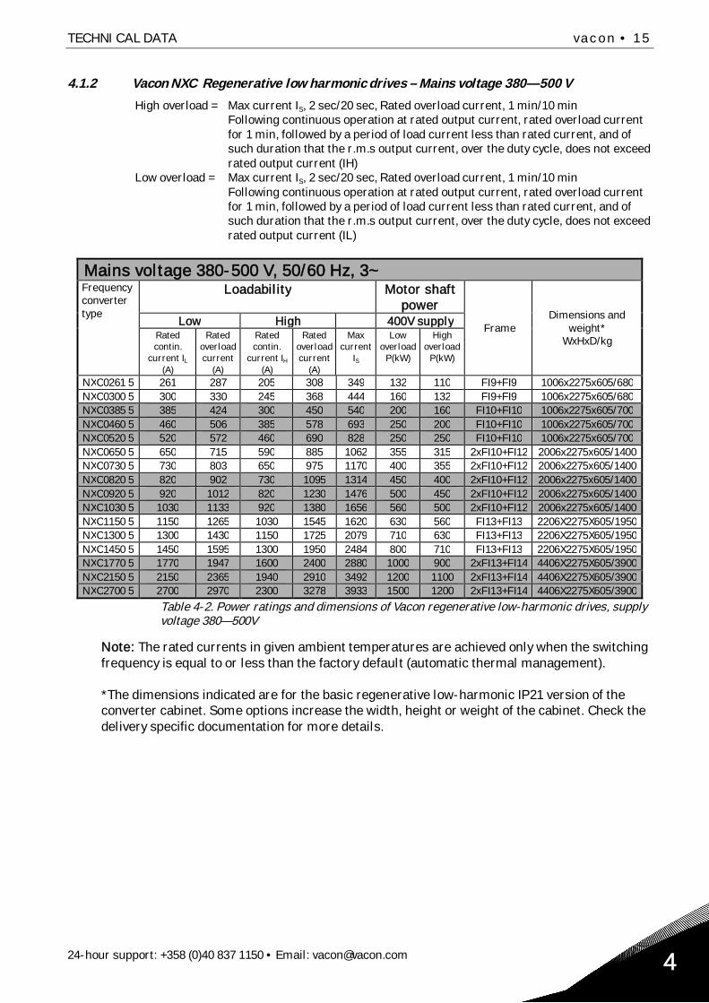
4.1.2 Vacon NXC Regenerative low harmonic drives – Mains voltage 380—500 V
High overload = Max current IS, 2 sec/20 sec, Rated overload current, 1 min/10 minFollowing continuous operation at rated output current, rated overload currentfor 1 min, followed by a period of load current less than rated current, and ofsuch duration that the r.m.s output current, over the duty cycle, does not exceedrated output current (IH)
Low overload = Max current IS, 2 sec/20 sec, Rated overload current, 1 min/10 minFollowing continuous operation at rated output current, rated overload currentfor 1 min, followed by a period of load current less than rated current, and ofsuch duration that the r.m.s output current, over the duty cycle, does not exceedrated output current (IL)
Mains voltage 380-500 V, 50/60 Hz, 3~Frequencyconvertertype
Loadability Motor shaftpower
FrameDimensions and
weight*WxHxD/kg
Low High 400V supplyRatedcontin.
current IL
(A)
Ratedoverloadcurrent
(A)
Ratedcontin.
current IH
(A)
Ratedoverloadcurrent
(A)
Maxcurrent
IS
Lowoverload
P(kW)
Highoverload
P(kW)
NXC0261 5 261 287 205 308 349 132 110 FI9+FI9 1006x2275x605/680NXC0300 5 300 330 245 368 444 160 132 FI9+FI9 1006x2275x605/680NXC0385 5 385 424 300 450 540 200 160 FI10+FI10 1006x2275x605/700NXC0460 5 460 506 385 578 693 250 200 FI10+FI10 1006x2275x605/700NXC0520 5 520 572 460 690 828 250 250 FI10+FI10 1006x2275x605/700NXC0650 5 650 715 590 885 1062 355 315 2xFI10+FI12 2006x2275x605/1400NXC0730 5 730 803 650 975 1170 400 355 2xFI10+FI12 2006x2275x605/1400NXC0820 5 820 902 730 1095 1314 450 400 2xFI10+FI12 2006x2275x605/1400NXC0920 5 920 1012 820 1230 1476 500 450 2xFI10+FI12 2006x2275x605/1400NXC1030 5 1030 1133 920 1380 1656 560 500 2xFI10+FI12 2006x2275x605/1400NXC1150 5 1150 1265 1030 1545 1620 630 560 FI13+FI13 2206X2275X605/1950NXC1300 5 1300 1430 1150 1725 2079 710 630 FI13+FI13 2206X2275X605/1950NXC1450 5 1450 1595 1300 1950 2484 800 710 FI13+FI13 2206X2275X605/1950NXC1770 5 1770 1947 1600 2400 2880 1000 900 2xFI13+FI14 4406X2275X605/3900NXC2150 5 2150 2365 1940 2910 3492 1200 1100 2xFI13+FI14 4406X2275X605/3900NXC2700 5 2700 2970 2300 3278 3933 1500 1200 2xFI13+FI14 4406X2275X605/3900
Table 4-2. Power ratings and dimensions of Vacon regenerative low-harmonic drives, supplyvoltage 380—500V
Note: The rated currents in given ambient temperatures are achieved only when the switchingfrequency is equal to or less than the factory default (automatic thermal management).
*The dimensions indicated are for the basic regenerative low-harmonic IP21 version of theconverter cabinet. Some options increase the width, height or weight of the cabinet. Check thedelivery specific documentation for more details.

16 • vacon TECHNICAL DATA
Tel. +358 (0)201 2121 • Fax +358 (0)201 212 2054
4.1.3 Vacon NXP/C 6 – Mains voltage 500—690 V
High overload = Max current IS, 2 sec/20 sec, Rated overload current, 1 min/10 minFollowing continuous operation at rated output current, rated overload currentfor 1 min, followed by a period of load current less than rated current, and ofsuch duration that the r.m.s output current, over the duty cycle, does not exceedrated output current (IH)
Low overload = Max current IS, 2 sec/20 sec, Rated overload current, 1 min/10 minFollowing continuous operation at rated output current, rated overload currentfor 1 min, followed by a period of load current less than rated current, and ofsuch duration that the r.m.s output current, over the duty cycle, does not exceedrated output current (IL)
Mains voltage 500-690 V, 50/60 Hz, 3~Frequencyconvertertype
Loadability Motor shaft power
FrameDimensions and
weight*WxHxD/kg
Low High 690V supply 575V supplyRatedcontin.
current IL
(A)
Ratedoverloadcurrent
(A)
Ratedcontin.
current IH
(A)
50%overloadcurrent
(A)
Maxcurrent
IS
Lowoverload
P(kW)
Highoverload
P(kW)
Lowoverload
P(hp)
Highoverload
P(hp)
NX_0125 6 125 138 100 150 200 110 90 125 100 FR9 606x2275x605/371NX_0144 6 144 158 125 188 213 132 110 150 125 FR9 606x2275x605/371NX_0170 6 170 187 144 216 245 160 132 150 150 FR9 606x2275x605/371NX_0208 6 208 229 170 255 289 200 160 200 150 FR9 606x2275x605/371NX_0261 6 261 287 208 312 375 250 200 250 200 FR10 606x2275x605/341NX_0325 6 325 358 261 392 470 315 250 300 250 FR10 606x2275x605/371NX_0385 6 385 424 325 488 585 355 315 400 300 FR10 606x2275x605/371NX_0416 6 416** 416** 325 488 585 400** 315 450** 300 FR10 606x2275x605/403NX_0460 6 460 506 385 578 693 450 355 450 400 FR11 806x2275x605/524NX_0502 6 502 552 460 690 828 500 450 500 450 FR11 806x2275x605/524NX_0590 6 590** 649** 502** 753** 904** 560** 500** 600** 500** FR11 806x2275x605/577NX_0650 6 650 715 590 885 1062 630 560 650 600 FR12 1206x2275x605/745NX_0750 6 750 825 650 975 1170 710 630 800 650 FR12 1206x2275x605/745NX_0820 6 820** 902** 650 975 1170 800** 630 800** 650 FR12 1206x2275x605/745NX_0920 6 920 1012 820 1230 1410 900 800 900 800 FR13 1406x2275x605/1000NX_1030 6 1030 1130 920 1380 1755 1000 900 1000 900 FR13 1406x2275x605/1000NX_1180 6 1180** 1298** 1030** 1463** 1755** 1150** 1000** 1100** 1000** FR13 1406x2275x605/1000NX_1500 6 1500 1650 1300 1950 2340 1500 1300 1500 1350 FR14 2406X2275X605/2350NX_1900 6 1900 2090 1500 2250 2700 1800 1500 2000 1500 FR14 2806X2275X605/2440NX_2250 6 2250 2475 1900 2782 3335 2000 1800 2300 2000 FR14 2806X2275X605/2500
Table 4-3. Power ratings and dimensions of Vacon NX 6- and 12-pulse drives, supply voltage 500—690V.
Note: The rated currents in given ambient temperatures are achieved only when the switchingfrequency is equal to or less than the factory default (automatic thermal management).
*The dimensions indicated are for the basic 6-pulse IP21 version of the converter cabinet. Some op-tions increase the width, height or weight of the cabinet. Check the delivery specific documentationfor more details.
** Maximum ambient temperature +35°C

TECHNICAL DATA vacon • 17
24-hour support: +358 (0)40 837 1150 • Email: [email protected] 4
4.1.4 Vacon NXC Regenerative low harmonic drives – Mains voltage 525—690 V
High overload = Max current IS, 2 sec/20 sec, Rated overload current, 1 min/10 minFollowing continuous operation at rated output current, rated overload currentfor 1 min, followed by a period of load current less than rated current, and ofsuch duration that the r.m.s output current, over the duty cycle, does not exceedrated output current (IH)
Low overload = Max current IS, 2 sec/20 sec, Rated overload current, 1 min/10 minFollowing continuous operation at rated output current, rated overload currentfor 1 min, followed by a period of load current less than rated current, and ofsuch duration that the r.m.s output current, over the duty cycle, does not exceedrated output current (IL)
Mains voltage 525-690 V, 50/60 Hz, 3~Frequencyconvertertype
Loadability Motor shaftpower Frame
Dimensions andweight*
WxHxD/kgLow High 690V supplyRatedcontin.
current IL
(A)
Ratedoverloadcurrent
(A)
Ratedcontin.
current IH
(A)
50%overloadcurrent
(A)
Maxcurrent
IS
Lowoverload
P(kW)
Highoverload
P(kW)
NXC0125 6 125 138 100 150 200 110 90 FI9+FI9 606x2275x605/371NXC0144 6 144 158 125 188 213 132 110 FI9+FI9 606x2275x605/371NXC0170 6 170 187 144 216 245 160 132 FI9+FI9 606x2275x605/371NXC0208 6 208 229 170 255 289 200 160 FI9+FI9 606x2275x605/371NXC0261 6 261 287 208 312 375 250 200 FI10+FI10 606x2275x605/341NXC0325 6 325 358 261 392 470 315 250 FI10+FI10 606x2275x605/371NXC0385 6 385 424 325 488 585 355 315 FI10+FI10 606x2275x605/371NXC0416 6 416** 416** 325 488 585 400** 315 FI10+FI10 606x2275x605/403NXC0460 6 460 506 385 578 693 450 355 2xFI10+FI12 806x2275x605/524NXC0502 6 502 552 460 690 828 500 450 2xFI10+FI12 806x2275x605/524NXC0590 6 590** 649** 502** 753** 904** 560** 500** 2xFI10+FI12 806x2275x605/577NXC0650 6 650 715 590 885 1062 630 560 2xFI10+FI12 1206x2275x605/745NXC0750 6 750 825 650 975 1170 710 630 2xFI10+FI12 1206x2275x605/745NXC0820 6 820** 902** 650 975 1170 800** 630 2xFI10+FI12 1206x2275x605/745NXC0920 6 920 1012 820 1230 1410 900 800 FI13+FI13 1406x2275x605/1000NXC1030 6 1030 1130 920 1380 1755 1000 900 FI13+FI13 1406x2275x605/1000NXC1180 6 1180** 1298** 1030** 1463** 1755** 1150** 1000** FI13+FI13 1406x2275x605/1000NXC1500 6 1500 1650 1300 1950 2340 1500 1300 2xFI13+FI14 2406X2275X605/2350NXC1900 6 1900 2090 1500 2250 2700 1800 1500 2xFI13+FI14 2806X2275X605/2440NXC2250 6 2250 2475 1900 2782 3335 2000 1800 2xFI13+FI14 2806X2275X605/2500
Table 4-4. Power ratings and dimensions of Vacon regenerative low-harmonic drives, supply voltage 525-690V.
Note: The rated currents in given ambient temperatures are achieved only when the switchingfrequency is equal to or less than the factory default (automatic thermal management).
*The dimensions indicated are for the basic regenerative low-harmonic IP21 version of the convertercabinet. Some options increase the width, height or weight of the cabinet. Check the delivery specificdocumentation for more details.
** Maximum ambient temperature +35°C

18 • vacon TECHNICAL DATA
Tel. +358 (0)201 2121 • Fax +358 (0)201 212 2054
4.2 Technical data
Mainsconnection
Input voltage Uin 380…500V; 500…690V; –10%…+10%380...500V;525...690V; –10%…+10% (regenerative drives)
Input frequency 45…66 HzConnection to mains Once per minute or less (normal case);
Motorconnection
Output voltage 0—Uin
Continuous outputcurrent
Ambient temperature max. +40°CSee Table 4-1 and Table 4-3.
Overloadability High: 1.5 x IH (1 min/10 min), Low: 1.1 x IL (1 min/10min)
Starting current IS for 2 s every 20 sOutput frequency 0…320 Hz; (higher with special SW)
Controlcharacteristics
Control performance Open Loop Vector Control (5-150% of base speed):speed control 0.5%, dynamic 0.3%sec, torque lin. <2%,torque rise time ~5 ms
Closed Loop Vector Control (entire speed range):speed control 0.01%, dynamic 0.2%sec, torque lin. <2%,torque rise time ~2 ms
Switching frequency NX_5:NX_6:
1…6 kHz; Factory default 3.6 kHz *1…6 kHz; Factory default 1.5 kHz *
Frequency referenceAnalogue inputPanel reference
Resolution 0.1% (10-bit), accuracy ±1%Resolution 0.01 Hz
Field weakening point 8…320 HzAcceleration time 0.1…3000 secDeceleration time 0.1…3000 secBraking DC brake: 30% * TN (without brake option); flux braking
Ambientconditions
Ambient operatingtemperature
–10°C (no frost)…+40ºC
Storage temperature –40°C…+70°CRelative humidity 0 to 95% RH, non-condensing, non-corrosive,
no dripping waterAir quality:- chemical vapours- mechanical particles
IEC 721-3-3, unit in operation, class 3C2IEC 721-3-3, unit in operation, class 3S2
Cabinet surface treatment Nanoceramic pretreatment. Anodic dipcoat-priming andtextured powder-coating
Altitude 100% load capacity (no derating) up to 1,000 m1-% derating for each 100m above 1000; max. 3000m(690V max 2000m)
VibrationEN50178/EN60068-2-6
Displacement amplitude 0.25 mm (peak) at 5…31 HzMax acceleration 1 G at 31…150 HzUse anti-vibration mountings under the drive if extravibration resistance is required
ShockEN50178, EN60068-2-27
UPS Drop Test (for applicable UPS weights)Storage and shipping: max 15 G, 11 ms (in package)
Enclosure class IP21/NEMA1 standard in entire kW/HP rangeIP54/NEMA12 option in entire kW/HP range
(Continues on next page)
*The rated currents in given ambient temperatures are achieved only when the switching frequency isequal to or less than the factory default. Thermal management might reduce the switching frequency.

TECHNICAL DATA vacon • 19
24-hour support: +358 (0)40 837 1150 • Email: [email protected] 4
EMC (at defaultsettings)
Immunity Fulfils all EMC immunity requirementsEmissions EMC level L: EN 61800-3 (2004), Category C3
EMC level T: Low earth-current solution for IT-networks, EN 61800-3 (2004), Category C4 (can bemodified from level L units
Safety EN 50178 (1997), EN 60204-1 (1996), EN 60950 (2000, 3rdedition) (as relevant), CE, UL, CUL, EN 61800-5; (see unitnameplate for more detailed approvals)
Controlconnections(factory defaultI/O)
Analogue input voltage 0…+10V, Ri = 200k , (–10V…+10V joystick control)Resolution 0.1%, accuracy ±1%
Analogue input current 0(4)…20 mA, Ri = 250 differential; Resolution 0.1%,accuracy ±1%
Digital inputs (6) Positive or negative logic; 18…30VDCAuxiliary voltage +24V, ±15%, max volt. ripple < 100mVrms; max. 250mA
Dimensioning: max. 1000mA/control boxOutput reference voltage +10V, ±3%, max. load 10mAAnalogue output 0(4)…20mA; RL max. 500 ; Resolution 10 bit;
Accuracy ±2%Digital outputs Open collector output, 50mA/48VRelay outputs 2 programmable change-over relay outputs
Switching capacity: 24VDC/8A, 250VAC/8A, 125VDC/0.4AMin. switching load: 5V/10mA
Thermistor input (OPT-A3)
Galvanically isolated, Rtrip = 4.7 k
Protections Overvoltage trip limitUndervoltage trip limit
NX_5: 911VDC; NX_6: 1200VDCNX_5: 333VDC; NX_6: 460 VDC
Earth fault protection In case of earth fault in motor or motor cable, only thefrequency converter is protected
Mains supervision Trips if any of the input phases is missingMotor phase supervision Trips if any of the output phases is missingOvercurrent protection YesUnit overtemperatureprotection
Yes
Motor overload protection YesMotor stall protection YesMotor underloadprotection
Yes
Short-circuit protection of+24V and +10V referencevoltages
Yes
Table 4-5. Technical data

20 • vacon MOUNTING
Tel. +358 (0)201 2121 • Fax +358 (0)201 212 2055
5. MOUNTING
5.1 Dimensions
The table below shows the dimensional drawing of the basic cabinet. Please note that certain NXCoptions will further affect the total width or height of the cabinet. Always refer to the delivery specificinformation for the exact dimensions.
Figure 5-1. Basic cabinet dimensions
Type Dimensions [mm] IP21 Dimensions [mm] IP54W1 H1 D1 W1 H1 D1
0261—0520 50125—0416 6 606** 2275* 605 606** 2400* 605
0650—0730 50460—0590 6 806** 2275* 605 806** 2400* 605
0820—1030 50650—0820 6 1206** 2275* 605 1206** 2400* 605
1150 5 1406** 2275* 605 1206** 2400* 6051300—1450 5 1606** 2275* 605 1606 2400 605
0920—1180 6 1406** 2275* 605 1406 2400 6051500 6 2406 2275* 605 2406** 2400* 6051770—2150 51900—2250 6
2806 2275* 605 2806** 2400* 605
Table 5-1. NXC 6-pulse drives cabinet dimensions
H1
W1
D1

MOUNTING vacon • 21
24-hour support: +358 (0)40 837 1150 • Email: [email protected] 5
Type Dimensions [mm] IP21 Dimensions [mm] IP54W1 H1 D1 W1 H1 D1
0385—0520 50261—0416 6 606** 2275* 605 606** 2400* 605
0590—0730 50460—0590 6 806** 2275* 605 806** 2400* 605
0820—1030 50650—0820 6 1206** 2275* 605 1206** 2400* 605
1150 50920—1180 6 1406** 2275* 605 1406** 2400* 605
1300—1450 5 2006** 2275* 605 2006** 2400* 6051770—2150 51500—2250 6 2806** 2275* 605 2806** 2400* 605
Table 5-2. NXC 12-pulse drives cabinet dimensions
Type Dimensions [mm] IP21 Dimensions [mm] IP54W1 H1 D1 W1 H1 D1
0261—0520 50125—0416 6 1006** 2275* 605 1006** 2405* 605
0590—1030 50460—0820 6 2006** 2275* 605 2006** 2405* 605
1150—1450 50920—1180 6 2206** 2275* 605 2206** 2445* 605
1770—2700 51500—2250 6 4406** 2275* 605 4406** 2445* 605
Table 5-3. NXC regenerative drive low-harmonic cabinet dimensions
* the options +GPL or +GPH (Plinth) increase the height by 100mm or 200mm respectively** some options, e.g. +CIT (Top input cabling +400mm), +COT (Top output cabling +400mm) and +ODU(output du/dt filter +400mm) affect the width of the cabinet

22 • vacon MOUNTING
Tel. +358 (0)201 2121 • Fax +358 (0)201 212 2055
5.2 Lifting the unit out of the transport packaging
The unit is delivered either in a wooden box or a wooden cage. The box may be transported eitherhorizontally or vertically, while transportation of the cage in a horizontal position is not allowed.Always refer to shipping marks for more detailed information. To lift the unit out of the box, uselifting equipment capable of handling the weight of the cabinet.There are lifting lugs on the top of the cabinet and these lugs can be used to lift the cabinet into anupright position and to move it to the place needed.
Figure 5-2. Lifting the unit
Note: Location of lifting lugs varies between different frames
Recycle the packaging material according to local regulations.
5.3 Fixing the unit to the floor or to the wall
The cabinet should always be fixed to the floor or to the wall. Depending on installation conditions,the cabinet sections can be fixed in different ways. There are holes in the front corners which can beused for fixing. Additionally, the rails on the top of the cabinet have fixing lugs for fixing the cabinetto the wall.
Welding of the cabinet might risk sensitive components in the converter.Ensure that no grounding currents can flow through any part of the converter.
Min 60°
Min 60°
Min 60°

MOUNTING vacon • 23
24-hour support: +358 (0)40 837 1150 • Email: [email protected] 5
5.3.1 Fixing to the floor and to the wall
In installations where the cabinet is mounted against the wall, it is more convenient to fix the top ofthe cabinet to the wall. Fix the cabinet in the two front corners to the floor with bolts. Fix the top partto the wall with bolts. Note that the rails and the fixing lugs can be moved horizontally to make surethe cabinet stands in a horizontal position. In converters consisting of more than one cabinet section,fix all sections in the same way.
Figure 5-3. Fixing the cabinet to the floor and to the wall
5.3.2 Fixing to the floor only
Note: This option is not available for FR13 and bigger units. For fixing FR13 and bigger unitssee delivery specific documentation.
If bottom-only fixing is used, additional fixing brackets (Rittal part.nr. 8800.210) or equivalent arenecessary. Fix the cabinet to the floor in the front with bolts and use the fixing brackets in themiddle. Fix all cabinet sections in the same way.
Figure 5-4. Fixing all for corners to the floor

24 • vacon MOUNTING
Tel. +358 (0)201 2121 • Fax +358 (0)201 212 2055
1 1 1
3 3 3
2 2 2
Terminal numbers
5.4 AC choke connections
Note: The NXC regenerative low-harmonic drive incorporates an LCL filter instead of AC chokes andthis instruction can be ignored.
The AC input choke carries out several functions in the Vacon NX 6- and 12-pulse frequencyconverter. The input choke is needed as an essential component for motor control, to protect theinput and DC-link components against abrupt changes of current and voltage as well as to functionas a protection against harmonics.The NXC 6- and 12-pulse frequency converter is equipped with one or more input AC chokes. Thechokes have two inductance levels to optimise the functionality at different supply voltages. In theinstallation phase, the wiring of the chokes should be checked and changed if needed (not for FR9).The input is always connected to terminal #1 (see picture below) and should not be changed. Theoutput of the choke should be connected to terminal #2 or #3 (see picture below) according to thetable below. The terminals are marked with inductance values and applicable voltage.In units FR10 to FR12, the connection is changed by moving the cable to the appropriate terminals.In FR13/14, the bridges of the busbar connection should be moved according to the settings shown in thetable.
In units with two or more parallel chokes (some FR11 as well as all FR12 andFR13) all chokes have to be wired in the same way. If chokes are wireddifferently the converter may be damaged.
Supply voltage Converterconnection(terminals)
400-480Vac/50-60Hz(500V unit)
2
500Vac/50Hz(500V unit)
3
500Vac/50Hz(690V unit)
3
575-690Vac/50-60Hz(690V unit)
3
Figure 5-5. Input chokes
Figure 5-6. Input chokes tapping in FR13/14 units
Move the bridge plate to changetapping

MOUNTING vacon • 25
24-hour support: +358 (0)40 837 1150 • Email: [email protected] 5
5.5 Auxiliary voltage transformer tappings
Note: An auxiliary voltage transformer is always included as standard in NXC regenerative low-harmonic drives.
If the drive is ordered with an auxiliary voltage transformer for 230V auxiliary voltage supply (+ATxoption) the tappings of the transformer have to be set according to the mains voltage.
The tappings of the transformer in 500V drives is by default set to 400V and in 690V drives to 690Vunless otherwise ordered.
Locate the transformer in the lower part of the cabinet. The primary side of the transformer hastappings that correspond to standard main voltages. Change to tapping to correspond to the mainsvoltage in use.

26 • vacon MOUNTING
Tel. +358 (0)201 2121 • Fax +358 (0)201 212 2055
5.6 Cooling
5.6.1 Free space around the cabinet
Enough space must be left above and in front of the cabinet to ensure sufficient cooling and spacefor maintenance.The amount of cooling air required is indicated in the table below. Also make sure that the tempera-ture of the cooling air does not exceed the maximum ambient temperature of the converter.
Figure 5-7. Space to be left free above (left) and in front of (right) the cabinet
Type Cooling air required [m3/h)0261—0300 50125—0208 6
1000
0385—0520 50261—0416 6
2000
0650—0730 50460—0590 6
3000
0820—1030 50650—0820 6
4000
1300—1450 5 (6-p)1300—1450 6 (12-p)
60007000
1150 50920—1180 6
5000
1500 6 (6-p) 90001770—2150 51900—2250 6 10000
Table 5-4. Required cooling air for NXC 6- and 12-pulse drives
200 mm
800 mm

MOUNTING vacon • 27
24-hour support: +358 (0)40 837 1150 • Email: [email protected] 5
Type Cooling air required [m3/h)0261—0520 50125—0416 6 3100
0590—1030 50460—0820 6 6200
1150—1450 50920—1180 6 7700
1770—2700 51500—2250 6 15400
Table 5-5. Required cooling air for NXC regenerative low-harmonic drives

28 • vacon MOUNTING
Tel. +358 (0)201 2121 • Fax +358 (0)201 212 2055
5.7 Power losses
The power loss of the frequency converter varies greatly with load and output frequency as well aswith the switching frequency used. For dimensioning of cooling or ventilation equipment for electri-cal rooms the following generic formula gives a good approximation of the heat losses at nominalconditions:
Ploss [kw] = Pmot [kW] x 0,025
CABLING AND CONNECTIONS vacon • 29
24-hour support: +358 (0)40 837 1150 • Email: [email protected] 6
6. CABLING AND CONNECTIONS
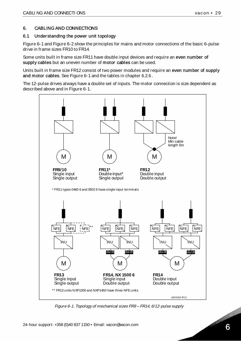
6.1 Understanding the power unit topology
Figure 6-1 and Figure 6-2 show the principles for mains and motor connections of the basic 6-pulsedrive in frame sizes FR10 to FR14.
Some units built in frame size FR11 have double input devices and require an even number ofsupply cables but an uneven number of motor cables can be used.
Units built in frame size FR12 consist of two power modules and require an even number of supplyand motor cables. See Figure 6-1 and the tables in chapter 6.2.6 .
The 12-pulse drives always have a double set of inputs. The motor connection is size dependent asdescribed above and in Figure 6-1.
M M M
ud1011k4.fh11
M M M
NFE NFE NFE
INU
NFE NFE NFE
INU INU INU INU
NFE NFE NFE NFE**
du/dt du/dtdu/dt du/dt
FR9/10Single inputSingle output
FR11*Double input*Single output
FR12Double inputDouble output
Note!Min cablelength 5m
* FR11 types 0460 6 and 0502 6 have single input terminals
FR13Single inputSingle output
FR14, NX 1500 6Single inputDouble output
FR14Double inputDouble output
** FR13 units NXP1300 and NXP1450 have three NFE units.
Figure 6-1. Topology of mechanical sizes FR9 – FR14, 6/12-pulse supply

30 • vacon CABLING AND CONNECTIONS
Tel. +358 (0)201 2121 • Fax +358 (0)201 212 2056
ud1011k17.fh11
M
INU
AFE
Singleinput
Singleoutput
FI9-10
INU
AFE
Singleinput
Singleoutput
FI12
INU
AFE
M
M
INU
AFE
Singleinput
Singleoutput
FI13
INU
AFE
Doubleinput
Doubleoutput
FI14
INU
AFE
M
du/dt du/dt
Figure 6-2. Topology of mechanical sizes NXC regenerative low-harmonic drives FI9 – FI14
Note! Some options affect the wiring direction and principle for power cables; always check deliveryspecific documentation for exact information.
CABLING AND CONNECTIONS vacon • 31
24-hour support: +358 (0)40 837 1150 • Email: [email protected] 6
6.2 Power connections
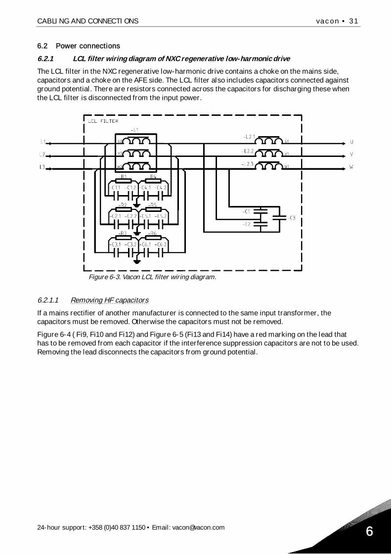
6.2.1 LCL filter wiring diagram of NXC regenerative low-harmonic drive
The LCL filter in the NXC regenerative low-harmonic drive contains a choke on the mains side,capacitors and a choke on the AFE side. The LCL filter also includes capacitors connected againstground potential. There are resistors connected across the capacitors for discharging these whenthe LCL filter is disconnected from the input power.
Figure 6-3. Vacon LCL filter wiring diagram.
6.2.1.1 Removing HF capacitors
If a mains rectifier of another manufacturer is connected to the same input transformer, thecapacitors must be removed. Otherwise the capacitors must not be removed.
Figure 6-4 ( Fi9, Fi10 and Fi12) and Figure 6-5 (Fi13 and Fi14) have a red marking on the lead thathas to be removed from each capacitor if the interference suppression capacitors are not to be used.Removing the lead disconnects the capacitors from ground potential.

32 • vacon CABLING AND CONNECTIONS
Tel. +358 (0)201 2121 • Fax +358 (0)201 212 2056
Figure 6-4. HF capacitors in NXC regenerative low-harmonic drive mechanical sizes Fi9,Fi10 and Fi12 LCLfilter.
Figure 6-5. HF capacitors in NXC regenerative low-harmonic drive mechanical sizes Fi13-Fi14 LCL filter.
Remove Remove
RemoveRemove
RemoveRemove
RemoveRemove

CABLING AND CONNECTIONS vacon • 33
24-hour support: +358 (0)40 837 1150 • Email: [email protected] 6
6.2.2 Mains and motor cables
The mains cables are connected to terminals L1, L2 and L3 (12-pulse units 1L1, 1L2, 1L3, 2L1, 2L2,2L3) and the motor cables to terminals marked with U, V and W, see Figure 6-7.
In converters consisting of double input sections, an even number of input cables is required. Inconverters consisting of double power modules an even number of motor cables is needed. Seetables 6-2 to 6-6 for cabling recommendations.
In 12-pulse drives with double inputs or outputs it is very important that the same cabledimensions, type and routing is used for all cables. In case the cabling between theconverter modules is not symmetrical, unequal load might occur and reduce loadabilityor even damage the converter.
In units with double motor outputs the motor cables must not be connected together inthe converter end. Always connect the parallel motor cables together in the motor endonly. The minimum motor cable length is 5m.
If a safe switch between the frequency converter and the motor is used, make sure thatit is switched on before setting the frequency converter in run state.
The output cables to the motor must be 360o EMC earthed. Separate EMC grounding clamps aresupplied with NXC FR9 if an output filter is used and with all drives of sizes FR/Fi10-12. In NXCFR/Fi13-14, EMC grounding is implemented directly through cable glands and grounding clamps areunnecessary. See chapter 6.2.2.1 for more information on EMC grounding for FR/Fi13-14.The EMCgrounding clamps can, for instance, be installed on the mounting plate in front of the AC choke asshown in Figure 6-6 below. The EMC grounding clamps must be suited to the output cable diameterto give a 360o contact with the cables. See chapters 6.2.6 and 6.2.7 for output cable diameters. SeeFigure 6-6.
Figure 6-6. Installing EMC grounding
For more detailed cable installation instructions, see chapter 8, step 6.
PE rail
EMC grounding
Cable fixing clamps

34 • vacon CABLING AND CONNECTIONS
Tel. +358 (0)201 2121 • Fax +358 (0)201 212 2056
Use cables with a temperature rating of at least +70 C. As a rule of thumb, cables and the fuses canbe dimensioned according to the frequency converter nominal OUTPUT current which you can findon the rating plate. Dimensioning according to the output current is recommended because thefrequency converter input current never significantly exceeds the output current.
Tables 6-2 and show the minimum dimensions of Cu- and Al-cables and the recommended aR fusesizes.
If the motor temperature protection of the drive (see Vacon All in One Application Manual) is used asan overload protection, the cable should be chosen accordingly. If three or more cables are usedparallelly (per block) in bigger units each cable requires a separate overload protection.
Cable type Level L(2nd environment)
Level T
Mains cable 1 1Motor cable 2 1/2*Control cable 4 4
Table 6-1. Cable types required to meet standards
*Recommended
Level L = EN61800-3, 2nd environment
Level T = For IT networks
1 = Power cable intended for fixed installation and the specific mainsvoltage. Shielded cable not required (DRAKA NK CABLES - MCMK orsimilar recommended)
2 = Symmetrical power cable equipped with concentric protection wire andintended for the specific mains voltage (DRAKA NK CABLES - MCMK orsimilar recommended).
4 = Screened cable equipped with compact low-impedance shield (DRAKANKCABLES - JAMAK, SAB/ÖZCuY-O or similar).
Note: The EMC requirements are fulfilled at factory defaults of switching frequencies (all frames).
CABLING AND CONNECTIONS vacon • 35
24-hour support: +358 (0)40 837 1150 • Email: [email protected] 6
PE
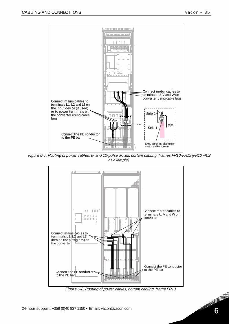
Connect mains cables toterminals L1, L2 and L3 onthe input device (if used)or to power terminals onthe converter using cablelugs
Connect the PE conductorto the PE bar
Connect motor cables toterminals U, V and W onconverter using cable lugs
EMC-earthing clamp formotor cable screen
Strip 1
Strip 2
Figure 6-7. Routing of power cables, 6- and 12-pulse drives, bottom cabling, frames FR10-FR12 (FR10 +ILSas example).
Connect mains cables toterminals L1, L2 and L3(behind the plexiglass) onthe converter
Connect the PE conductorto the PE bar
Connect motor cables toterminals U, V and W onconverter
Connect the PE conductorto the PE bar
Figure 6-8. Routing of power cables, bottom cabling, frame FR13

36 • vacon CABLING AND CONNECTIONS
Tel. +358 (0)201 2121 • Fax +358 (0)201 212 2056
Connect mains cables toterminals L1, L2 and L3(behind the plexiglass) onthe converter
Connect the PEconductors to the PE bar
Connect motor cables toterminals U, V and W onconverter
Connect the PEconductors to the PE bar
Figure 6-9. Routing of power cables, bottom cabling, frame FR14
PE
Connect motor cables toterminals U, V and W onconverter using cable lugs
EMC-earthing clamp formotor cable screen
Strip 1
Strip 2
Connect mains cables toterminals L1, L2 and L3 onthe power terminals on theconverter using cable lugs
Connect the PE conductorto the PE bar
Figure 6-10. Routing of power cables, bottom cabling, frame Fi10

CABLING AND CONNECTIONS vacon • 37
24-hour support: +358 (0)40 837 1150 • Email: [email protected] 6
Connect mains cablesto terminals L1, L2 andL3 on the AC drive
Connect motor cablesto terminals U, V and Won converter
Connect the PEconductor to the PE bar
Figure 6-11. Routing of power cables, bottom cabling, frame Fi12 +ODU (optional)
Connect motor cables toterminals U, V and W onconverter
Connect mains cables toterminals L1, L2 and L3(behind the plexiglass) onthe converter
Figure 6-12. Routing of power cables, bottom cabling, frame Fi13

38 • vacon CABLING AND CONNECTIONS
Tel. +358 (0)201 2121 • Fax +358 (0)201 212 2056
Figure 6-13. Routing of power cables, bottom cabling, frame Fi14
6.2.2.1 Routing of power cables through bottom of cabinet
Route the supply and motor cables through the cabinet bottom as shown in Figure 6-14. To conformto the EMC requirements, a particular cable gland shall be used. The cable glands are designed tobe used together with screened cables when electromagnetic compatibility (EMC) is required.
Figure 6-14. Routing of supply and power cables

CABLING AND CONNECTIONS vacon • 39
24-hour support: +358 (0)40 837 1150 • Email: [email protected] 6
ud1011k11.fh11
Rubber sealing
Bush ring
Cable
Assembly plate
PE(N) screen
Metal sock
Fastening springCable tie
Figure 6-15. Components of the cable gland set
Installing the cable gland
Unless the cable gland is already installed by the manufacturer, follow the procedure below to dothis:
1. Assemble the rubber sealing in the narrow groove of the bush ring. Make sure that the gapbetween the assembly plate and the sealing is tight.
2. Since the fastening spring is rather stiff, we recommend to use a cone-shaped tool to fit themetal sock in the bush ring and then to clamp it with the spring bent into a ring shape. Draw thesock over the groove far enough to be easily fastened with the spring. Make sure that the springclamps the sock at 360°.
3. Roll up the sock as far as the fastening ring and remove the cone-shaped tool if used. Now thecable installation is easier and the cable will not damage the sock.
4. Clamp the sock to the shielding of cable with a cable tie.
Cone-shaped tool
Metal sock
Fastening spring

40 • vacon CABLING AND CONNECTIONS
Tel. +358 (0)201 2121 • Fax +358 (0)201 212 2056

CABLING AND CONNECTIONS vacon • 41
24-hour support: +358 (0)40 837 1150 • Email: [email protected] 6
6.2.2.2 Installation of ferrite rings (+OCM) on the motor cable
Modern PWM Frequency converters based on IGBT transistors generate output pulses having shortrise times (0,1...0,2 µs). Those pulse edges increase the stress for motor insulation and also gener-ate high frequency common mode voltages on the motor output. Common mode voltage increasesemitted radio interferences and might cause danger of bearing currents when larger motor frames(> 100kW) are used.
Motor cable selection and installation has to be done according to the requirements of the installa-tion environment. The screen of the motor cable has to be connected to earth at every end (fre-quency converter, safety switch, motor etc.) so that high frequency impedance is as low as possible.The best solution is a 360-degree grounding. If this is difficult to do then connect the PE conductor toground or panel wall (metallic) right after the stripping point of jacket of cable (see Figure 6-16,alternatives a and b). Influence of common mode voltages can easily be additionally attenuated byinstalling a common mode choke on the motor output. The simplest way is to use ferrite rings with adiameter large enough to allow the motor phase conductors to be slipped through.
Installation of the ferrite rings:Slip only the phase conductors through the rings; leave the cable screen below and outside therings, see Figure 6-16. Separate the PE conductor. In case of parallel motor cables, reserve an equalamount of ferrite ring sets for each cable and feed all the phase conductors of one cable throughone set of rings.
Vacon's delivery consists of fixed sets of ferrite rings (option). When ferrite rings are used toattenuate the risk of bearing damages, use always two ferrite ring sets per motor cable.
Note! The ferrite rings are only additional protection. The basic protection against bearing currentsis an insulated bearing.
Figure 6-16. Installation of ferrite rings on single (left) and parallel (right) motor cables
ud1011k8.fh8
Ferrite rings
Metallic wallof cabinet
Screen connectedto earth
Motor cable
PE
Mains cable
High frequencygrounding
Motor cable
Ferrite rings
Metallic wallof cabinet
Screen connetedto earth

42 • vacon CABLING AND CONNECTIONS
Tel. +358 (0)201 2121 • Fax +358 (0)201 212 2056
6.2.3 Thermal supervision of option +ODU
Option +ODU can also be equipped with a thermal supervision which will indicate if the filtertemperature has exceeded safe limits. Always refer to cabinet specific electrical drawings fordetails.This NC contact is wired to the external fault input DIN3 by factory default.
NOTE! If the external fault input DIN3 is used for other purposes, make sure that the +ODU fansupervision wiring is changed accordingly. It is also possible to connect the NC contact in series withRUN or RUN ENABLE commands (see relevant application manual for more details).
6.2.4 DC supply and brake resistor cables
Vacon 6- and 12-pulse frequency converters can optionally be equipped with terminals for DC supplyand with an external brake resistor. These terminals are marked with B-, B+/R+ and R-. The DC busconnection is made to terminals B– and B+ and the brake resistor connection to R+ and R– on theconverter module. The converter module terminals can also optionally be wired to customerterminals in the cabinet.
Make sure that the converter is equipped with a brake chopper before connecting abrake resistor.
Do not connect the brake resistor between the terminals B- and B+ as this will damagethe drive.
6.2.5 Control cable
For information on control cables see chapter 8.2. The control cables are routed down to the bottomof the cabinet in the left inner side of the cabinet.

CABLING AND CONNECTIONS vacon • 43
24-hour support: +358 (0)40 837 1150 • Email: [email protected] 6
6.2.6 Cable and fuse sizes, 380-500V units
The table below shows typical cable sizes and types that can be used with the converter. The finalselection should be made according to local regulations, cable installation conditions and cablespecification.
6.2.6.1 6-pulse drives
Frame Type IL
[A]Bussmann/Ferraz Shawmut
fuse typeFuse In
[A]
Mains and motorcable1) [mm2]
No. ofsupplycables
No. ofmotorcables
FR9NX0261 5 261 170M5813 (3 pcs)
NH2UD69V500PV (3 pcs) 700/500 Cu: 3*185+95 or2*(3*120+70)
Even/Odd Even/Odd
NX0300 5 300 170M5813 (3 pcs)NH2UD69V500PV (3 pcs) 700/500 Cu: 2*(3*120+70) Even/Odd Even/Odd
FR10
NX0385 5 385 170M5813 (3 pcs)NH2UD69V700PV (3 pcs) 700 Cu: 2*(3*120+70)
Al: 2*(3*185Al+57Cu) Even/Odd Even/Odd
NX0460 5 460 170M8547 (3 pcs)NH3UD69V1000PV (3 pcs)
1250/1000
Cu: 2*(3*150+70)Al: 2*(3*240Al+72Cu) Even/Odd Even/Odd
NX0520 5 520 170M8547 (3 pcs)NH3UD69V1000PV (3 pcs)
1250/1000
Cu: 2*(3*185+95)Al: 2*(3*300Al+88Cu) Even/Odd Even/Odd
FR11
NX0590 5 590 170M5813 (6 pcs)NH2UD69V700PV (6 pcs) 700 Cu: 2*(3*240+120)
Al: 4*(3*120Al+41Cu) Even Even/Odd
NX0650 5 650 170M5813 (6 pcs)NH2UD69V700PV (6 pcs) 700 Cu: 4*(3*95+50)
Al: 4*(3*150Al+41Cu) Even Even/Odd
NX0730 5 730 170M5813 (6 pcs)NH2UD69V700PV (6 pcs) 700 Cu: 4*(3*120+70)
Al: 4*(3*185Al+57Cu) Even Even/Odd
FR12
NX0820 5 820 170M8547 (6 pcs)NH3UD69V1000PV (6 pcs)
1250/1000
Cu: 4*(3*150+70)Al: 4*(3*185Al+57Cu) Even Even
NX0920 5 920 170M8547 (6 pcs)NH3UD69V1000PV (6 pcs)
1250/1000
Cu: 4*(3*150+70)Al: 4*(3*240Al+72Cu) Even Even
NX1030 5 1030 170M8547 (6 pcs)NH3UD69V1000PV (6 pcs)
1250/1000
Cu: 4*(3*185+95)Al: 4*(3*300Al+88Cu) Even Even
FR13
NX1150 5 1150 No additional drive fuses needed Cu:5*(3*150+70)Al:6*(3*185+57Cu) Even/Odd Even/Odd
NX1300 5 1300 No additional drive fuses needed Cu:5*(3*185+95)Al:6*(3*240+72Cu) Even/Odd Even/Odd
NX1450 5 1450 No additional drive fuses needed Cu:6*(3*185+95)Al:6*(3*240+72Cu) Even/Odd Even/Odd
FR14NX1770 5 1770 No additional drive fuses needed Cu: 6*(3*240+120)
Al: 8*(3*240+72Cu) Even Even
NX2150 5 2150 No additional drive fuses neededCu: 8*(3*185+95)
Al: 8*(3*300+88Cu) Even Even
Table 6-2. Cable and fuse sizes for Vacon NX_5, 6-pulse supply
1)Based on correction factor 0.7. Cables are laid on a cable ladder side by side, three ladders on top of each other.Ambient temperature is 30°C (86°F). EN60204-1 and IEC 60364-5-523.

44 • vacon CABLING AND CONNECTIONS
Tel. +358 (0)201 2121 • Fax +358 (0)201 212 2056
6.2.6.2 12-pulse drives
Frame Type IL
[A]Bussmann / FerrazShawmut fuse type
Fuse In
[A]
Mains and motorcable1) [mm2]
No. ofsupplycables
No. ofmotorcables
FR10
NX0385 5 385 170M5813 (3 pcs)NH2UD69V500PV (3 pcs) 700/500 Cu: 2*(3*120+70)
Al: 2*(3*185Al+57Cu) Even/Odd Even/Odd
NX0460 5 460 170M5813 (3 pcs)NH2UD69V500PV (3 pcs) 700/500 Cu: 2*(3*150+70)
Al: 2*(3*240Al+72Cu) Even/Odd Even/Odd
NX0520 5 520 170M5813 (3 pcs)NH2UD69V500PV (3 pcs) 700/500 Cu: 2*(3*185+95)
Al: 2*(3*300Al+88Cu) Even/Odd Even/Odd
FR11
NX0590 5 590 170M5813 (6 pcs)NH2UD69V700PV (6 pcs) 700 Cu: 2*(3*240+120)
Al: 4*(3*120Al+41Cu) Even Even/Odd
NX0650 5 650 170M5813 (6 pcs)NH2UD69V700PV (6 pcs) 700 Cu: 4*(3*95+50)
Al: 4*(3*150Al+41Cu) Even Even/Odd
NX0730 5 730 170M5813 (6 pcs)NH2UD69V700PV (6 pcs) 700 Cu: 4*(3*120+70)
Al: 4*(3*185Al+57Cu) Even Even/Odd
FR12
NX0820 5 820 170M8547 (6 pcs)NH3UD69V1000PV (6 pcs) 1250/1000 Cu: 4*(3*150+70)
Al: 4*(3*185Al+57Cu) Even Even
NX0920 5 920 170M8547 (6 pcs)NH3UD69V1000PV (6 pcs) 1250/1000 Cu: 4*(3*150+70)
Al: 4*(3*240Al+72Cu) Even Even
NX1030 5 1030 170M8547 (6 pcs)NH3UD69V1000PV (6 pcs) 1250/1000 Cu: 4*(3*185+95)
Al: 4*(3*300Al+88Cu) Even Even
FR13
NX1150 5 1150 No additional drive fuses needed Cu: 4(3*240+170)Al: 6*(3*185Al+57Cu) Even Even/Odd
NX1300 5 1300 No additional drive fuses needed Cu: 6(3*150+70)Al: 6*(3*240Al+72Cu) Even Even/Odd
NX1450 5 1450 No additional drive fuses needed Cu: 6(3*185+95)Al: 6*(3*240Al+72Cu) Even Even/Odd
FR14NX1770 5 1770 No additional drive fuses needed Cu: 6*(3*240+120)
Al: 8*(3*240Al+72Cu) Even Even
NX2150 5 2150 No additional drive fuses neededCu: 8*(3*185+95)
Al: 8*(3*300Al+88Cu) Even Even
Table 6-3. Cable and fuse sizes for Vacon NX_5, 12-pulse supply
1) Based on correction factor 0.7. Cables are laid on a cable ladder side by side, three ladders on top of each other. Ambienttemperature is 30°C (86°F). EN60204-1 and IEC 60364-5-523.

CABLING AND CONNECTIONS vacon • 45
24-hour support: +358 (0)40 837 1150 • Email: [email protected] 6
6.2.6.3 Regenerative low-harmonic drives
Frame Type IL
[A]Bussmann/FerrazShawmut fuse type
Fuse In
[A]Mains and motor
cable1) [mm2]
No. ofsupplycables
No. ofmotorcables
Fi9NX0261 5 261 170M6202 (3 pcs)
NH2UD69V500PV (3 pcs) 700/500 Cu: 3*185+95 or2*(3*120+70)
Even/Odd Even/Odd
NX0300 5 300 170M5813 (3 pcs)NH2UD69V500PV (3 pcs) 700/500 Cu: 2*(3*120+70) Even/Odd Even/Odd
Fi10
NX0385 5 385 170M5813 (3 pcs)NH2UD69V700PV (3 pcs) 700 Cu: 2*(3*120+70)
Al: 2*(3*185Al+57Cu) Even/Odd Even/Odd
NX0460 5 460 170M8547 (3 pcs)NH3UD69V1000PV (3 pcs)
1250/1000
Cu: 2*(3*150+70)Al: 2*(3*240Al+72Cu) Even/Odd Even/Odd
NX0520 5 520 170M8547 (3 pcs)NH3UD69V1000PV (3 pcs)
1250/1000
Cu: 2*(3*185+95)Al: 2*(3*300Al+88Cu) Even/Odd Even/Odd
Fi12
NX0820 5 820 170M8547 (6 pcs)NH3UD69V1000PV (6 pcs)
1250/1000
Cu: 4*(3*150+70)Al: 4*(3*185Al+57Cu) Even Even
NX0920 5 920 170M8547 (6 pcs)NH3UD69V1000PV (6 pcs)
1250/1000
Cu: 4*(3*150+70)Al: 4*(3*240Al+72Cu) Even Even
NX1030 5 1030 170M8547 (6 pcs)NH3UD69V1000PV (6 pcs)
1250/1000
Cu: 4*(3*185+95)Al: 4*(3*300Al+88Cu) Even Even
Fi13
NX1150 5 1150 No additional drive fuses needed Cu:5*(3*150+70)Al:6*(3*185+57Cu) Even/Odd Even/Odd
NX1300 5 1300 No additional drive fuses needed Cu:5*(3*185+95)Al:6*(3*240+72Cu) Even/Odd Even/Odd
NX1450 5 1450 No additional drive fuses needed Cu:6*(3*185+95)Al:6*(3*240+72Cu) Even/Odd Even/Odd
Fi14NX1770 5 1770 No additional drive fuses needed
Cu: 6*(3*240+120)Al: 8*(3*240+72Cu) Even Even
NX2150 5 2150 No additional drive fuses neededCu: 8*(3*185+95)
Al: 8*(3*300+88Cu) Even Even
NX2700 5 2700 No additional drive fuses needed Cu: 8*(3*185+95)Al: 8*(3*300+88Cu) Even Even
Table 6-4. Cable and aR fuse sizes for Vacon NX_5 Regenerative low-harmonic drive.
1) Based on correction factor 0.7. Cables are laid on a cable ladder side by side, three ladders on top of each other. Ambienttemperature is 30°C (86°F). EN60204-1 and IEC 60364-5-523.

46 • vacon CABLING AND CONNECTIONS
Tel. +358 (0)201 2121 • Fax +358 (0)201 212 2056
6.2.7 Cable and fuse sizes, 500/525-690V units
The table below shows typical cable sizes and types that can be used with the converter.The final selection should be done according to local regulations, cable installation conditions andcable specification.
6.2.7.1 6-pulse drives
Frame Type IL
[A]Bussmann/
Ferraz Shawmut fuse typeFuse In
[A]
Mains and motorcable1)
[mm2]
No ofsupplycables
No ofmotorcables
FR9
NX0125 6NX0144 6NX0170 6NX0208 6
125144170
170M3819 (3 pcs)NH1UD69V400PV (3 pcs) 400 Cu: 3*95+50 Even/Odd Even/Odd
208 170M3819 (3 pcs)NH1UD69V400PV (3 pcs)
400 Cu: 3*150+70 Even/Odd Even/Odd
FR10
NX0261 6 261 170M5813 (3 pcs)NH2UD69V700PV (3 pcs)
700 Cu: 3*185+95Al: 2*(3*95Al+29Cu) Even/Odd Even/Odd
NX0325 6 325 170M5813 (3 pcs)NH2UD69V700PV (3 pcs)
700 Cu: 2*(3*95+50)Al: 2*(3*150Al+41Cu) Even/Odd Even/Odd
NX0385 6 385 170M5813 (3 pcs)NH2UD69V700PV (3 pcs)
700 Cu: 2*(3*120+70)Al: 2*(3*185Al+57Cu) Even/Odd Even/Odd
NX0416 6 416 170M5813 (3 pcs)NH2UD69V700PV (3 pcs)
700 Cu: 2*(3*150+70)Al: 2*(3*185Al+57Cu) Even/Odd Even/Odd
FR11
NX0460 6 460 170M8547 (3 pcs)NH3UD69V1000PV (3 pcs)
1250 Cu: 2*(3*150+70)Al: 2*(3*240Al+72Cu) Even/Odd Even/Odd
NX0502 6 502 170M8547 (3 pcs)NH3UD69V1000PV (3 pcs)
1250 Cu: 2*(3*185+95)Al: 2*(3*300Al+88 Cu) Even/Odd Even/Odd
NX0590 6 590 170M5813 (6 pcs)NH2UD69V700PV (6 pcs)
700 Cu: 2*(3*240+120)Al: 4*(3*120Al+41Cu) Even Even/Odd
FR12
NX0650 6 650 170M5813 (6 pcs)NH2UD69V700PV (6 pcs)
700 Cu: 4*(3*95+50)Al: 4*(3*150Al+41Cu) Even Even
NX0750 6 750 170M5813 (6 pcs)NH2UD69V700PV (6 pcs)
700 Cu: 4*(3*120+70)Al: 4*(3*150Al+41Cu) Even Even
NX0820 6 820 170M5813 (6 pcs)NH2UD69V700PV (6 pcs)
700 Cu: 4*(3*150+70)Al: 4*(3*185Al+57Cu) Even Even
FR13
NX0920 6 920 No additional drive fuses needed Cu:4*(3*150+70)Al:4*(3*2405+72Cu) Even/Odd Even/Odd
NX1030 6 1030 No additional drive fuses needed Cu:4*(3*185+95)Al:5*(3*185+57Cu) Even/Odd Even/Odd
NX1180 6 1180 No additional drive fuses needed Cu:5*(3*185+95)Al:6*(3*185+72Cu) Even/Odd Even/Odd
FR14
NX1500 6 1500 No additional drive fuses needed Cu:6*(3*185+95)Al:8*(3*185+57Cu) Even/Odd Even
NX1900 6 1900 No additional drive fuses needed Cu:6*(3*240+120)Al:8*(3*240+72Cu) Even Even
NX2250 6 2250 No additional drive fuses needed Cu:8*(3*240+120)Al:8*(3*300+88Cu) Even Even
Table 6-5. Cable and aR fuse sizes for Vacon NX_6, 6-pulse supply
1) Based on correction factor 0.7. Cables are laid on a cable ladder side by side, three ladders on top of each other. Ambienttemperature is 30°C (86°F). EN60204-1 and IEC 60364-5-523.

CABLING AND CONNECTIONS vacon • 47
24-hour support: +358 (0)40 837 1150 • Email: [email protected] 6
6.2.7.2 12-pulse drives
Frame Type IL
[A]Bussmann
/Ferraz Shawmut fuse typeFuse In
[A]
Mains and motorcable1)
[mm2]
No ofsupplycables
No ofmotorcables
FR10
NX0261 6 261170M5813 (6 pcs)
NH2UD69V500PV (6 pcs) 700/500Cu: 2*(3*120+70)
Al: 2*(3*185Al+57Cu) Even/Odd Even/Odd
NX0325 6 325170M5813 (6 pcs)
NH2UD69V500PV (6 pcs) 700/500Cu: 2*(3*120+70)
Al: 2*(3*185Al+57Cu) Even/Odd Even/Odd
NX0385 6 385170M5813 (6 pcs)
NH2UD69V500PV (6 pcs) 700/500Cu: 2*(3*120+70)
Al: 2*(3*185Al+57Cu) Even/Odd Even/Odd
NX0416 6 416170M5813 (6 pcs)
NH2UD69V500PV (6 pcs) 700/500Cu: 2*(3*150+70)
Al: 2*(3*185Al+57Cu) Even/Odd Even/Odd
FR11
NX0460 6 460170M5813 (6 pcs)
NH2UD69V700PV (6 pcs) 700Cu: 2*(3*150+70)
Al: 2*(3*240Al+72Cu) Even/Odd Even/Odd
NX0502 6 502170M5813 (6 pcs)
NH2UD69V700PV (6 pcs) 700Cu: 2*(3*185+95)
Al: 2*(3*300Al+88 Cu) Even/Odd Even/Odd
NX0590 6 590170M5813 (6 pcs)
NH2UD69V700PV (6 pcs) 700Cu: 2*(3*240+120)
Al: 4*(3*120Al+41Cu) Even Even/Odd
FR12
NX0650 6 650170M5813 (6 pcs)
NH2UD69V700PV (6 pcs) 700Cu: 4*(3*95+50)
Al: 4*(3*150Al+41Cu) Even Even
NX0750 6 750170M5813 (6 pcs)
NH2UD69V700PV (6 pcs) 700Cu: 4*(3*120+70)
Al: 4*(3*150Al+41Cu) Even Even
NX0820 6 820170M5813 (6 pcs)
NH2UD69V700PV (6 pcs) 700Cu: 4*3*150+70)
Al: 4*(3*185Al+57Cu) Even Even
FR13
NX0920 6 920 No additional drive fuses neededCu:4x(3x150+70)
Al:4x(3x2405+72Cu) Even Even/Odd
NX1030 6 1030 No additional drive fuses needed Cu:4x(3x185+95)Al:6x(3x150+41Cu) Even Even/Odd
NX1180 6 1180 No additional drive fuses needed Cu:6x(3x185+95)Al:6x(3x185+72Cu) Even Even/Odd
FR14
NX1500 6 1500 No additional drive fuses needed Cu:6*(3*185+95)Al:8*(3*185+57Cu) Even Even
NX1900 6 1900 No additional drive fuses needed Cu:6*(3*240+120)Al:8*(3*240+72Cu) Even Even
NX2250 6 2250 No additional drive fuses needed Cu:8*(3*240+120)Al:8*(3*300+88Cu) Even Even
Table 6-6. Cable and aR fuse sizes for Vacon NX_6, 12-pulse supply
1) Based on correction factor 0.7. Cables are laid on a cable ladder side by side, three ladders on top of each other. Ambienttemperature is 30°C (86°F). EN60204-1 and IEC 60364-5-523.

48 • vacon CABLING AND CONNECTIONS
Tel. +358 (0)201 2121 • Fax +358 (0)201 212 2056
6.2.7.3 Regenerative low-harmonic drives
Frame Type IL
[A]Bussmann / FerrazShawmut fuse type
FuseIn
[A]
Mains and motorcable1)
[mm2]
No ofsupplycables
No ofmotorcables
Fi9
NX0125 6NX0144 6NX0170 6NX0208 6
125144170
170M3819 (3 pcs)NH1UD69V400PV (3 pcs)
400 Cu: 3*95+50 Even/Odd Even/Odd
208 170M3819 (3 pcs)NH1UD69V400PV (3 pcs)
400 Cu: 3*150+70 Even/Odd Even/Odd
Fi10
NX0261 6 261 170M5813 (3 pcs)NH2UD69V700PV (3 pcs)
700 Cu: 3*185+95Al: 2*(3*95Al+29Cu) Even/Odd Even/Odd
NX0325 6 325 170M5813 (3 pcs)NH2UD69V700PV (3 pcs)
700 Cu: 2*(3*95+50)Al: 2*(3*150Al+41Cu) Even/Odd Even/Odd
NX0385 6 385 170M5813 (3 pcs)NH2UD69V700PV (3 pcs)
700 Cu: 2*(3*120+70)Al: 2*(3*185Al+57Cu) Even/Odd Even/Odd
NX0416 6 416 170M5813 (3 pcs)NH2UD69V700PV (3 pcs)
700 Cu: 2*(3*150+70)Al: 2*(3*185Al+57Cu) Even/Odd Even/Odd
Fi12
NX0650 6 650 170M5813 (6 pcs)NH2UD69V700PV (6 pcs)
700 Cu: 4*(3*95+50)Al: 4*(3*150Al+41Cu) Even Even
NX0750 6 750 170M5813 (6 pcs)NH2UD69V700PV (6 pcs)
700 Cu: 4*(3*120+70)Al: 4*(3*150Al+41Cu) Even Even
NX0820 6 820 170M5813 (6 pcs)NH2UD69V700PV (6 pcs)
700 Cu: 4*(3*150+70)Al: 4*(3*185Al+57Cu) Even Even
Fi13
NX0920 6 920 No additional drive fuses needed Cu:4*(3*150+70)Al:4*(3*2405+72Cu) Even/Odd Even/Odd
NX1030 6 1030 No additional drive fuses needed Cu:4*(3*185+95)Al:5*(3*185+57Cu) Even/Odd Even/Odd
NX1180 6 1180 No additional drive fuses needed Cu:5*(3*185+95)Al:6*(3*185+72Cu) Even/Odd Even/Odd
Fi14
NX1500 6 1500 No additional drive fuses needed Cu:6*(3*185+95)Al:8*(3*185+57Cu) Even/Odd Even
NX1900 6 1900 No additional drive fuses needed Cu:6*(3*240+120)Al:8*(3*240+72Cu) Even Even
NX2250 6 2250 No additional drive fuses needed Cu:8*(3*240+120)Al:8*(3*300+88Cu) Even Even
6-7. Cable and aR fuse sizes for Vacon NX_6 Regenerative low-harmonic drive.
1) Based on correction factor 0.7. Cables are laid on a cable ladder side by side, three ladders on top of each other. Ambienttemperature is 30°C (86°F). EN60204-1 and IEC 60364-5-523.

LOW HARMONIC REGENERATIVE CABINET DRIVE vacon • 49
24-hour support +358 (0)40 837 1150 • Email: [email protected] 7
7. LOW HARMONIC REGENERATIVE CABINET DRIVE
This chapter describes the functionalities of control devices (switches, push-buttons and LED lamps) of theNXC low-harmonic regenerative drive (mechanical units FI9-14). The functionalities of additional “+”options are not described here.
7.1 NXC Low-Harmonic Regenerative Cabinet Pre-Charging and MCCB Operating Instructions
There are three different ways to control the DC pre-charging circuit and the circuit-breakers (MCCB) ofthe low harmonic regenerative drive. The desired control place or the manner of control can be selectedwith the REM-MAN-AUTO selector switch (-S6). The three possible control places/ways are:
MAN – Manual operation by the 0-1-Start switch on the cabinet doorREM – Remote operation with signals to the control terminalsAUTO – Automatic operation which automatically pre-charges and closes the MCCB when thesupply voltage is energized
Figure 7-1. MCCB Control selector switch (-S6)
7.1.1 Manual operation (MAN)
The operator can control the circuit-breaker (MCCB) and the charging circuit manually from the cabinetwhile the MCCB control switch –S6 is in Man position. The 0–1-Start switch is used for the local operationof the MCCB and pre-charging circuit.
Figure 7-2. 0-1-Start Control switch (-S10)
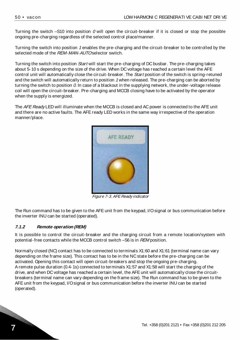
50 • vacon LOW HARMONIC REGENERATIVE CABINET DRIVE
Tel. +358 (0)201 2121 • Fax +358 (0)201 212 2057
Turning the switch –S10 into position 0 will open the circuit-breaker if it is closed or stop the possibleongoing pre-charging regardless of the selected control place/manner.
Turning the switch into position 1 enables the pre-charging and the circuit-breaker to be controlled by theselected mode of the REM-MAN-AUTO selector switch.
Turning the switch into position Start will start the pre-charging of DC busbar. The pre-charging takesabout 5-10 s depending on the size of the drive. When DC voltage has reached a certain level the AFEcontrol unit will automatically close the circuit-breaker. The Start position of the switch is spring-retunedand the switch will automatically return to position 1 when released. The pre-charging can be aborted byturning the switch to position 0. In case of a blackout in the supplying network, the under-voltage releasecoil will open the circuit-breaker. Pre-charging and MCCB closing have to be activated by the operatorwhen the supply is energized.
The AFE Ready LED will illuminate when the MCCB is closed and AC power is connected to the AFE unitand there are no active faults. The AFE ready LED works in the same way irrespective of the operationmanner/place.
Figure 7-3. AFE Ready indicator
The Run command has to be given to the AFE unit from the keypad, I/O signal or bus communication beforethe inverter INU can be started (operated).
7.1.2 Remote operation (REM)
It is possible to control the circuit-breaker and the charging circuit from a remote location/system withpotential-free contacts while the MCCB control switch –S6 is in REM position.
Normally closed (NC) contact has to be connected to terminals X1:60 and X1:61 (terminal name can varydepending on the frame size). This contact has to be in the NC state before the pre-charging can beactivated. Opening this contact will open circuit-breakers and stop the ongoing pre-charging.A remote pulse duration (0.4-1s) connected to terminals X1:57 and X1:58 will start the charging of thedrive, and when DC voltage has reached a certain level, the AFE unit will automatically close the circuit-breakers (terminal name can vary depending on the frame size). The Run command has to be given to theAFE unit from the keypad, I/O signal or bus communication before the inverter INU can be started(operated).

LOW HARMONIC REGENERATIVE CABINET DRIVE vacon • 51
24-hour support +358 (0)40 837 1150 • Email: [email protected] 7
Figure 7-4. Circuit diagram of remote contacts for the control of theMCCB and pre-charging circuit (NXC regenerative low-harmonic FR12)
In case of a voltage drop of <0.7xUN or a blackout in the supplying network, the undervoltage release coilwill open the circuit-breaker and pre-charging and MCCB closing has to be activated by the remotecharging pulse when the supply is energized.
7.1.3 Automatic operation (AUTO)
The pre-charging and closing of the circuit-breaker is automatically done when the REM-MAN-AUTOselector switch is in AUTO position and the supply voltage is energized. The pre-charging of the units willautomatically (directly) start when the control switch -S6 is turned into Auto position. The AFE unit willautomatically close the circuit-breakers after DC voltage has reached a certain level and the AFE READYLED will illuminate.
The unit will re-charge automatically and close the circuit-breakers if the main supply voltage has beencut and turned back on (e.g. voltage drop in the network). The 0-1-Start switch has to be in position 1 whichenables automatic function.
Turning the switch –S10 to position 0 will open the circuit-breaker even if the REM-MAN-AUTO selectorswitch is in AUTO position.
7.1.4 Circuit-Breaker TRIP due to overload or short-circuit
The electronic trip unit will open/trip the circuit-breaker in case of an overload or short circuit. The tripindication contacts of circuit-breakers are connected in series and if one of the circuit-breakers trips dueto an overload or short circuit current, it will automatically open/trip the other circuit-breakers. The MCCBFAULT LED will illuminate and indicate that the circuit breakers are in tripped state.
Figure 7-5. MCCB FAULT indicator

52 • vacon LOW HARMONIC REGENERATIVE CABINET DRIVE
Tel. +358 (0)201 2121 • Fax +358 (0)201 212 2057
In case of an overcurrent situation the fault that caused the circuit-breaker to trip should be identified andremoved before the circuit-breakers can be reset. The MCCB can only be reset by pressing the push button-S6 when the –S11 REM-MAN-AUTO switch is in MAN position.
Figure 7-6. MCCB Reset push-button (-S11)
This will reset the circuit-breaker and, at the same time in FR9, FR10 or FR12 solution, recharge thespring system of the motor operators. After this it is possible to pre-charge and close the circuit-breakersby methods described in previous chapters.

INSTALLATION INSTRUCTIONS vacon • 53
24-hour support +358 (0)40 837 1150 • Email: [email protected] 8
8. INSTALLATION INSTRUCTIONS
1 Before starting the installation, check that none of the components of thefrequency converter is live.
2 Make sure that the space where the converter is installed, and the con-verter itself, is clean and free from particles, dust or humidity that couldharm the converter when it is powered on.
3 Make sure the connection of the AC choke and the optional 230V auxiliaryvoltage transformer are suitable for the supply voltage in use (Seechapters 5.4 and 0).
4 Place the motor cables sufficiently far from other cables:Avoid placing the motor cables in long parallel lines with othercablesIf the motor cables run in parallel with other cables, note theminimum distances between the motor cables and other cablesgiven in table below.
The given distances also apply between the motor cables andsignal cables of other systems.The maximum length of the motor cables is 300m.If output du/dt filters (+ODU or +ODC options) are used the cablelength is limited according to the table below:
The motor cables should cross other cables at an angle of 90degrees.
5 If cable insulation checks are needed, see Chapter 8.1.1.
Maximum cablelength withdu/dt filter
Switchingfrequency
100m 3,6kHz300m 1,5kHz
Distancebetween cables
[m]
Shieldedcable[m]
0.3 501.0 300
Continues on the next page

54 • vacon INSTALLATION INSTRUCTIONS
Tel. +358 (0)201 2121 • Fax +358 (0)201 212 2058
6 Connect the cables:Strip the motor and mains cablesRemove the protection grids for the input terminals and theprotection covers on the converter module(s).Pull the cable through the bottom plate and fix the PE conductorto the PE bar of the cabinet.Connect the mains, motor and control cables into their respec-tive terminals. Use cable lugs on the power cables. In units withparallel cables (FR11 and FR12) make sure the cabling is fullysymmetrical.Fix the shields of the motor cable(s) to the cabinet by using theearthing clamps included in the delivery.For Information on cable installation according to ULregulations see Chapter 8.1.Make sure that the control cable wires do not come in contact withthe electronic components of the unit or control componentsinside the cabinet.If an external brake resistor (option) is used, connect its cable tothe appropriate terminal (R+/R–). Also make sure that the con-verter is equipped with a brake chopper (indicated in the type codeof the converter).Check the connection of the earth cable to the motor and the
frequency converter terminals marked with PE or .Connect the separate shield of the power cable to the earthterminals of the frequency converter, motor and the supply centre.
7 IMPORTANT: If an output filter (+ODU, +ODC or +OSI) is used, note thatthe switching frequency of the converter (parameter 2.6.9, ID601) mustbe set according to the specification of the output filter. Setting toohigh/low a switching frequency may damage the filter.
8.1 Cable installation and the UL standards
To meet the UL (Underwriters Laboratories) regulations, a UL-approved copper cable with a minimumheat-resistance of +60/75 C must be used. The cable must be suitable for use on a circuit capable ofdelivering not more than 100,000 rms symmetrical amperes, 600V maximum. Use Class 1 wire only.
The tightening torques of the terminals are given in Table 8-1.
Type Frame Tightening torque[Nm]
NX_2 0261—0300NX_5 0261—0300NX_6 0125—0208
FR9 40/22*
NX_5 0385—1450 FR10-14 40**NX_6 0261—1180 FR10-14 40**
Table 8-1. Tightening torques of terminals
* Tightening torque of terminal connection to the isolative base in Nm/in-lbs. NOTE: This value is needed only ifthe motor connection is made directly to the converter (no devices between converter and motor).** Apply counter torque to the nut on the other side of the terminal when tightening/loosening the terminal screwin order to avoid damage to the terminal.

INSTALLATION INSTRUCTIONS vacon • 55
24-hour support +358 (0)40 837 1150 • Email: [email protected] 8
8.1.1 Cable and motor insulation checks
1. Motor cable insulation checks
Disconnect the motor cable from terminals U, V and W of the frequency converter and from the motor.Measure the insulation resistance of the motor cable between each phase conductor as well asbetween each phase conductor and the protective ground conductor.
The insulation resistance must be >1M .
2. Mains cable insulation checks
Disconnect the mains cable from terminals L1, L2 and L3 of the frequency converter and from themains. Measure the insulation resistance of the mains cable between each phase conductor as well asbetween each phase conductor and the protective ground conductor.
The insulation resistance must be >1M .
3. Brake resistor cable insulation checks
Disconnect the brake resistor cable from terminals R+ and R- of the frequency converter and from thebrake resistor. Measure the insulation resistance of the cable between each conductor as well asbetween conductors and the protective ground conductor.
The insulation resistance must be >1M .
4. Motor insulation checks
Disconnect the motor cable from the motor and open the bridging connections in the motor connectionbox. Measure the insulation resistance of each motor winding. The measurement voltage must equal atleast the motor nominal voltage but not exceed 1000 V. The insulation resistance must be >1M .
5. Brake resistor insulation check
Disconnect the brake resistor cable and measure the insulation from the power terminals to theground terminal. The measurement voltage must equal at least the motor nominal voltage but notexceed 1000 V. The insulation resistance must be >1M .
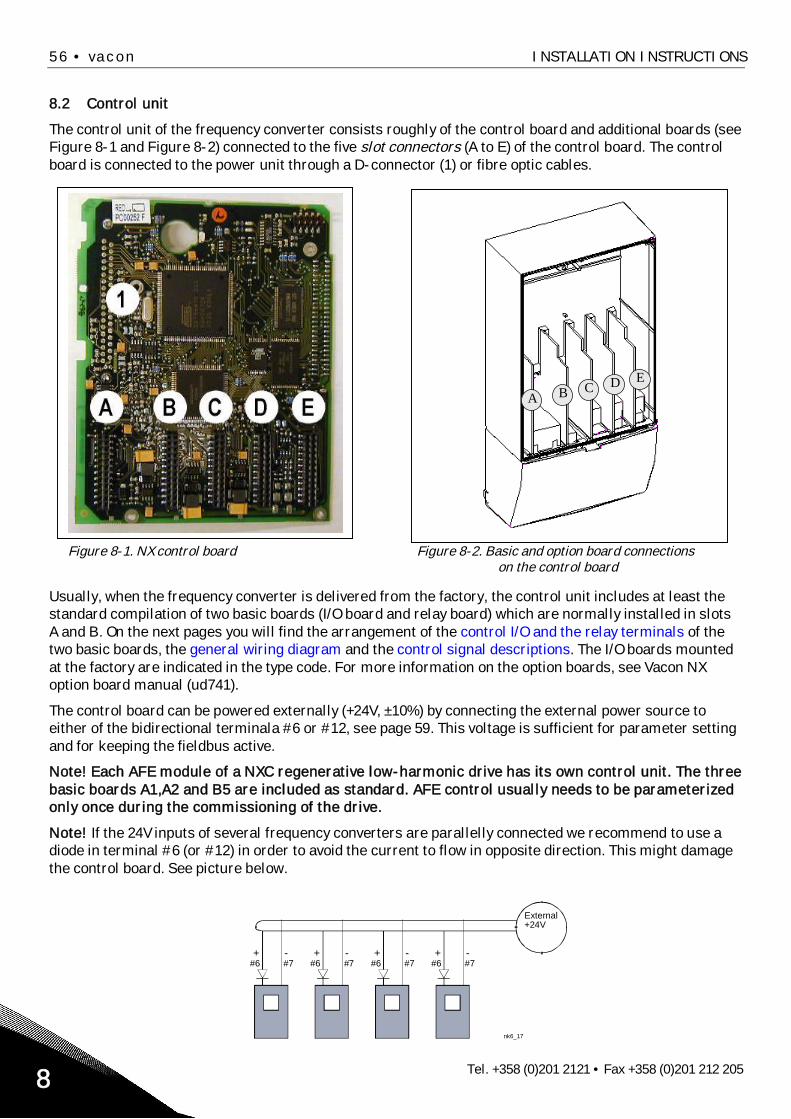
56 • vacon INSTALLATION INSTRUCTIONS
Tel. +358 (0)201 2121 • Fax +358 (0)201 212 2058
8.2 Control unit
The control unit of the frequency converter consists roughly of the control board and additional boards (seeFigure 8-1 and Figure 8-2) connected to the five slot connectors (A to E) of the control board. The controlboard is connected to the power unit through a D-connector (1) or fibre optic cables.
Figure 8-1. NX control board Figure 8-2. Basic and option board connectionson the control board
Usually, when the frequency converter is delivered from the factory, the control unit includes at least thestandard compilation of two basic boards (I/O board and relay board) which are normally installed in slotsA and B. On the next pages you will find the arrangement of the control I/O and the relay terminals of thetwo basic boards, the general wiring diagram and the control signal descriptions. The I/O boards mountedat the factory are indicated in the type code. For more information on the option boards, see Vacon NXoption board manual (ud741).
The control board can be powered externally (+24V, ±10%) by connecting the external power source toeither of the bidirectional terminala #6 or #12, see page 59. This voltage is sufficient for parameter settingand for keeping the fieldbus active.
Note! Each AFE module of a NXC regenerative low-harmonic drive has its own control unit. The threebasic boards A1,A2 and B5 are included as standard. AFE control usually needs to be parameterizedonly once during the commissioning of the drive.
Note! If the 24V inputs of several frequency converters are parallelly connected we recommend to use adiode in terminal #6 (or #12) in order to avoid the current to flow in opposite direction. This might damagethe control board. See picture below.
A B C D E
+ -#6 #7
+ -#6 #7
+ -#6 #7
+ -#6 #7
nk6_17
External+24V

INSTALLATION INSTRUCTIONS vacon • 57
24-hour support +358 (0)40 837 1150 • Email: [email protected] 8
8.2.1 Control connections
The basic control connections for boards A1 and A2/A3 are shown in Chapter 8.2.2.The signal descriptions are presented in the All in One Application Manual.
Figure 8-3. The I/O terminalsof the basic boards
Figure 8-4. General wiring diagram of the basic I/O board(OPT-A1)
Figure 8-5. General wiring diagram of the basic relay boards (OPT-A2/OPT-A3)
OPT-A2 OPT-A3
Board OPT-A1in slot A
Boards OPT-A2 andOPT-A3 in slot B
RO1/11/2
RO1/3
RO2/12/2
RO2/3
ac/dc
212223
242526
NX6_6.fh8
212223
2526
RO1/11/2
RO1/3
2/1RO2/2
ac/dc
2829
TI1+TI1-
+t
Switching:<8A/24Vdc,<0.4A/125Vdc,<2kVA/250VacContinuously:<2Arms
Basic relay boardOPT-A2
Switching:<8A/24Vdc,<0.4A/125Vdc,<2kVA/250VacContinuously:<2Arms
Basic relay boardOPT-A3
+10VrefAI1+GNDAI2+AI2-24VoutGNDDIN1DIN2DIN3CMA24VoutGNDDIN4DIN5DIN6CMBAO1+AO1-DO1
123456789
1011121314151617181920
24 V
GND
24 V
GND
U<+48VI<50mA
+
0(4)/20mARC<500
nk6_13
Basic I/O boardOPT-A1
Reference(voltage)
Reference(current)
Dotted line indicates the connection with inverted signals

58 • vacon INSTALLATION INSTRUCTIONS
Tel. +358 (0)201 2121 • Fax +358 (0)201 212 2058
8.2.1.1 Control cables
The control cables shall be at least 0.5 mm2 screened multicore cables, see Table 6-1. The maximumterminal wire size is 2.5 mm2 for the relay terminals and 1.5 mm2 for other terminals.
Find the tightening torques of the option board terminals in Table below.
Terminalscrew
Tightening torqueNm lb-in.
Relay andthermistor terminals
(screw M3)0.5 4.5
Other terminals(screw M2.6) 0.2 1.8
Table 8-2. Tightening torques of terminals
8.2.1.2 Galvanic isolation barriers
The control connections are isolated from the mains potential and the GND terminals are permanentlyconnected to ground. See Figure 8-6.The digital inputs are galvanically isolated from the I/O ground. The relay outputs are additionally double-isolated from each other at 300VAC (EN-50178).
Figure 8-6. Galvanic isolation barriers
L1 L2 L3
U V W
RO1/1RO1/2RO1/3
RO2/3RO2/2RO2/1
10VrefGND
GND+24V
AI1AI2+AI2 -
DIN1...DIN3CMADIN4...DIN6CMBAO1+AO2 -
DO1
nk6_15TI1+TI1-
Control I/Oground
Digital inputgroup A
Digital inputgroup B
AnalogueoutputDigitaloutput
Controlboard
Controlpanel
Gate drivers
Powerboard

INSTALLATION INSTRUCTIONS vacon • 59
24-hour support +358 (0)40 837 1150 • Email: [email protected] 8
8.2.2 Control terminal signals
OPT-A1Terminal Signal Technical information
1 +10 Vref Reference voltage Maximum current 10 mA2 AI1+ Analogue input,
voltage or currentSelection V or mA with jumper block X1 (see page 62):Default: 0– +10V (Ri = 200 k )
(-10V…..+10V Joy-stick control, selected with a jumper) 0– 20mA (Ri = 250 )
3 GND/AI1– Analogue input common Differential input if not connected to ground;Allows 20V differential mode voltage to GND
4 AI2+ Analogue input,voltage or current
Selection V or mA with jumper block X2 (see page 62):Default: 0– 20mA (Ri = 250 ) 0– +10V (Ri = 200 k )
(-10V…..+10V Joy-stick control, selected with a jumper)5 GND/AI2– Analogue input common Differential input if not connected to ground;
Allows 20V differential mode voltage to GND6 24 Vout
(bidirectional)24V auxiliary voltage 15%, maximum current 250mA (all boards total);150mA
(from single board); Can also be used as external powerbackup for the control unit (and fieldbus)
7 GND I/O ground Ground for reference and controls8 DIN1 Digital input 1
Ri = min. 5k18…30V = "1"
9 DIN2 Digital input 210 DIN3 Digital input 311 CMA Digital input common A for
DIN1, DIN2 and DIN3.Must be connected to GND or 24V of I/O terminal orto external 24V or GNDSelection with jumper block X3 (see page 62):
12 24 Vout(bidirectional)
24V auxiliary voltage Same as terminal #6
13 GND I/O ground Same as terminal #714 DIN4 Digital input 4
Ri = min. 5k18…30V = "1"
15 DIN5 Digital input 516 DIN6 Digital input 617 CMB Digital input common B for
DIN4, DIN5 and DIN6Must be connected to GND or 24V of I/O terminal or toexternal 24V or GNDSelection with jumper block X3 (see page 62):
18 AO1+ Analogue signal (+output) Output signal range:Current 0(4)–20mA, RL max 500 orVoltage 0—10V, RL >1kSelection with jumper block X6 (see page 62):
19 AO1– Analogue output common
20 DO1 Open collector output Maximum Uin = 48VDCMaximum current = 50 mA
Table 8-3. Control I/O terminal signals on basic I/O board OPT-A1

60 • vacon INSTALLATION INSTRUCTIONS
Tel. +358 (0)201 2121 • Fax +358 (0)201 212 2058
OPT-A2Terminal Signal Technical information
21 RO1/1 Relay output 1 Switching capacity 24VDC/8A250VAC/8A125VDC/0.4A
Min.switching load 5V/10mA
22 RO1/223 RO1/3
24 RO2/1 Relay output 2 Switching capacity 24VDC/8A250VAC/8A125VDC/0.4A
Min.switching load 5V/10mA
25 RO2/226 RO2/3
Table 8-4. Control I/O terminal signals on basic relay board OPT-A2
OPT-A3Terminal Signal Technical information
21 RO1/1 Relay output 1 Switching capacity 24VDC/8A250VAC/8A125VDC/0.4A
Min.switching load 5V/10mA
22 RO1/223 RO1/3
25 RO2/1 Relay output 2 Switching capacity 24VDC/8A250VAC/8A125VDC/0.4A
Min.switching load 5V/10mA26 RO2/2
28 TI1+Thermistor input
29 TI1–
Table 8-5. Control I/O terminal signals on basic relay board OPT-A3
8.2.2.1 Digital input signal inversions
The active signal level depends on which potential the common inputs CMA and CMB (terminals 11 and 17)are connected to. The alternatives are either +24V or ground (0 V). See Figure 8-7.
The 24-volt control voltage and the ground for the digital inputs and the common inputs (CMA, CMB) can beeither internal or external.
Figure 8-7. Positive/Negative logic
+24V
+24V
DIN1
DIN2
DIN3
CMA
DIN1
DIN2
DIN3
CMAnk6_16
Ground
Ground
Positive logic (+24V is the active signal) =the input is active when the switch is closed
Negative logic (0V is the active signal) =the input is active when the switch is closed.Requires setting of jumper X3 to position‘CMA/CMB isolated from ground’

INSTALLATION INSTRUCTIONS vacon • 61
24-hour support +358 (0)40 837 1150 • Email: [email protected] 8
8.2.2.2 Jumper selections on the OPT-A1 basic board
The user is able to customise the functions of the frequency converter to better suit his needs by selectingcertain positions for the jumpers on the OPT-A1 board. The positions of the jumpers determine the signaltype of analogue and digital inputs.
On the A1 basic board, there are four jumper blocks X1, X2, X3 and X6 each containing eight pins and twojumpers. The selectable positions of the jumpers are shown in Figure 8-9.
Figure 8-8. Jumper blocks on OPT-A1

62 • vacon INSTALLATION INSTRUCTIONS
Tel. +358 (0)201 2121 • Fax +358 (0)201 212 2058
Figure 8-9. Jumper selection for OPT-A1
If you change the AI/AO signal content also remember tochange the corresponding board parameter in menu M7.
A B C D
A B C D
A B C D
A B C D
A B C D
A B C D
A B C D
A B C D
A B C D
A B C D
Jumper block X1:AI1 mode
AI1 mode: Voltage input; 0...10V
AI1 mode: Voltage input; 0...10V (differential)
AI1 mode: Voltage input; -10...10V
Jumper block X2:AI2 mode
AI2 mode: 0...20mA; Current input
AI2 mode: Voltage input; 0...10V
AI2 mode: Voltage input; 0...10V (differential)
AI2 mode: Voltage input; -10...10V
Jumper block X3:CM A and CMB grounding
CMB connected to GNDCMA connected to GND
CMB isolated from GNDCMA isolated from GND
CMB and CMAinternally connected together,isolated from GND
= Factory default
Jumper block X 6:AO1 mode
AO1 mode: 0...20mA; Current output
AO1 mode: Voltage output; 0...10V
AI1 mode: 0...20mA; Current input

INSTALLATION INSTRUCTIONS vacon • 63
24-hour support +358 (0)40 837 1150 • Email: [email protected] 8
8.3 Connecting power supply and internal control cables
You might need to establish the fibre cable connections from the star coupler board to the power module.Connect the cables according to Figure 8-11.
The control unit uses 24 VDC supplied from the ASIC board, which is located on the left side of the powerunit 1. To access the board, remove the protective cover in front of the power module. Connect the powersupply cable to the X10 connector on the ASIC board and to the X2 connector on the rear side of the controlunit.
Figure 8-10. Connecting the power supply and control cables to the control unit, FR12
Each fibre optic cable has a number 1...8 and 11…18 marked on the cable shield at both cable ends.Connect each cable to the connectors marked with the same number on the ASIC board and on the rearside of the control unit. Additionally, you may have to connect the 4 fibre cables from the feedback board tothe star coupler board. The list of the optic signals can be found in chapter 8.4.
CAUTION! Be careful when connecting the fibre optic cables! Connecting the wires incorrectly willdamage power electronic components.
NOTE! The minimum bending radius for optical cables is 50mm.
Fix the cable bundle at two or more points, at least one at each end, to prevent damages to the cables.
Fasten the protective cover on the power unit when the work is finished.
X10
Power module 1ASIC board
Power module 2ASIC board
FB board
X2
Min bending radius 50 mm
Star coupler board

64 • vacon INSTALLATION INSTRUCTIONS
Tel. +358 (0)201 2121 • Fax +358 (0)201 212 2058
8.4 Optic fibre cables, signal listing and connections
Figure 8-11. Internal fibre cable connections
Star coupler board on control unit
H18 Trip signal from power module 2H17 VaconBus data from ASIC 2 to control boardH16 VaconBus data from control board to ASIC 2H15 ADC synchronization, power module 2H14 Phase W control, power module 2H13 Phase V control, power module 2H12 Phase U control, power module 2H11 Gate control enable, power module 2
H23 Feedback phase WH22 Feedback phase VH21 Feedback phase U
Terminals on ASIC board of power module 1
H1 Gate control enableH2 Phase U controlH3 Phase V controlH4 Phase W controlH5 ADC synchronizationH6 VaconBus data from control board to ASICH7 VaconBus data from ASIC to control board
Terminals on ASIC board of power module 2
H8 Trip signal from power module 1H7 VaconBus data from ASIC 1 to control boardH6 VaconBus data from control board to ASIC 1H5 ADC synchronization, power module 1H4 Phase W control, power module 1H3 Phase V control, power module 1H2 Phase U control, power module 1H1 Gate control enable, power module 1
H10 Trip signal
Terminals on FB board of power module 2
H1 Gate control enableH2 Phase U controlH3 Phase V controlH4 Phase W controlH5 ADC synchronizationH6 VaconBus data from control board to ASICH7 VaconBus data from ASIC to control board
H10 Trip signalH11 Feedback phase UH12 Feedback phase VH13 Feedback phase W
Terminals on FB board of power module 1
H12
H13
H14
H15
H16
H17
H18
H11
H23
H22
H21
H2
H3
H4
H5
H6
H7
H8
H1
H7
H6
H5
H4
H3
H2
H1
H10
H7
H6
H5
H4
H3
H2
H1H10
H13
H12
H11
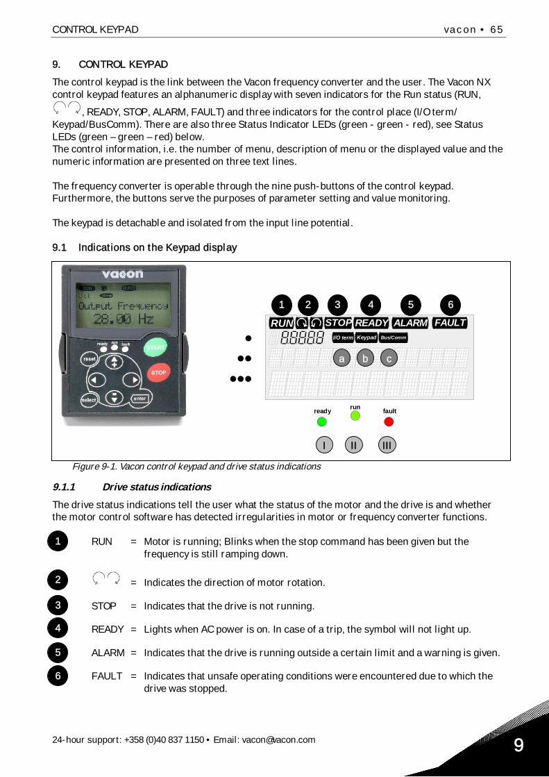
CONTROL KEYPAD vacon • 65
24-hour support: +358 (0)40 837 1150 • Email: [email protected] 9
9. CONTROL KEYPAD
The control keypad is the link between the Vacon frequency converter and the user. The Vacon NXcontrol keypad features an alphanumeric display with seven indicators for the Run status (RUN,
, READY, STOP, ALARM, FAULT) and three indicators for the control place (I/O term/Keypad/BusComm). There are also three Status Indicator LEDs (green - green - red), see StatusLEDs (green – green – red) below.The control information, i.e. the number of menu, description of menu or the displayed value and thenumeric information are presented on three text lines.
The frequency converter is operable through the nine push-buttons of the control keypad.Furthermore, the buttons serve the purposes of parameter setting and value monitoring.
The keypad is detachable and isolated from the input line potential.
9.1 Indications on the Keypad display
Figure 9-1. Vacon control keypad and drive status indications
9.1.1 Drive status indications
The drive status indications tell the user what the status of the motor and the drive is and whetherthe motor control software has detected irregularities in motor or frequency converter functions.
RUN = Motor is running; Blinks when the stop command has been given but thefrequency is still ramping down.
= Indicates the direction of motor rotation.
STOP = Indicates that the drive is not running.
READY = Lights when AC power is on. In case of a trip, the symbol will not light up.
ALARM = Indicates that the drive is running outside a certain limit and a warning is given.
FAULT = Indicates that unsafe operating conditions were encountered due to which thedrive was stopped.
READY FAULTSTOPRUNBus/CommKeypadI/O term
ALARM
runready fault
1 2 3 4 5 6
a b
I II III
c
1
2
3
4
5
6

66 • vacon CONTROL KEYPAD
Tel. +358 (0)201 2121 • Fax +358 (0)201 212 2059
9.1.2 Control place indications
The symbols I/O term, Keypad and Bus/Comm (see Figure 9-1) indicate the choice of control placemade in the Keypad control menu (M3) (see chapter 9.3.3).
I/O term = I/O terminals are the selected control place; i.e. START/STOP commandsor reference values etc. are given through the I/O terminals.
Keypad = Control keypad is the selected control place; i.e. the motor can bestarted or stopped, or its reference values etc. altered from the keypad.
Bus/Comm = The frequency converter is controlled through a fieldbus.
9.1.3 Status LEDs (green – green – red)
The status LEDs light up in connection with the READY, RUN and FAULT drive status indicators.
= Illuminates with the AC power connected to the drive and no faults are active.Simultaneously, the drive status indicator READY is lit up.
= Illuminates when the drive is running. Blinks when the STOP button has beenpushed and the drive is ramping down.
= Blinks when unsafe operating conditions were encountered due to which thedrive was stopped (Fault Trip). Simultaneously, the drive status indicatorFAULT blinks on the display and the fault description can be seen, seechapter 9.3.4, Active Faults.
9.1.4 Text lines
The three text lines ( , , ) provide the user with information on his present location in thekeypad menu structure as well as with information related to the operation of the drive.
= Location indication; displays the symbol and number of menu, parameter etc. Example: M2 = Menu 2 (Parameters); P2.1.3 = Acceleration time
= Description line; Displays the description of menu, value or fault.
= Value line; Displays the numerical and textual values of references,parameters etc. and the number of submenus available in each menu.
b
c
a
I
II
III

CONTROL KEYPAD vacon • 67
24-hour support: +358 (0)40 837 1150 • Email: [email protected] 9
9.2 Keypad push-buttons
The Vacon alphanumeric control keypad features 9 push-buttons that are used for the control of thefrequency converter (and motor), parameter setting and value monitoring.
Figure 9-2. Keypad push-buttons
9.2.1 Button descriptions
reset = This button is used to reset active faults (see Chapter 9.3.4).
select = This button is used to switch between two latest displays. May be usefulwhen you want to see how the changed new value influences some othervalue.
enter = The Enter button serves for: 1) confirmation of selections 2) fault history reset (2…3 seconds)
= Browser button up Browse the main menu and the pages of different submenus. Edit values.
= Browser button down Browse the main menu and the pages of different submenus. Edit values.
= Menu button left Move backward in menu. Move cursor left (in parameter menu). Exit edit mode. Hold down for 3 seconds to return to main menu.
= Menu button right Move forward in menu. Move cursor right (in parameter menu). Enter edit mode.
= Start button. Pressing this button starts the motor if the keypad is the active control
place. See Chapter 9.3.3.
= Stop button. Pressing this button stops the motor (unless disabled by parameter
R3.4/R3.6). See Chapter 9.3.3.
start
stop
+
-

68 • vacon CONTROL KEYPAD
Tel. +358 (0)201 2121 • Fax +358 (0)201 212 2059
9.3 Navigation on the control keypad
The data on the control keypad are arranged in menus and submenus. The menus are used forexample for the display and editing of measurement and control signals, parameter settings(chapter 9.3.2), reference values and fault displays (chapter 9.3.4). Through the menus, you can alsoadjust the contrast of the display (page 87).
The first menu level consists of menus M1 to M7 and is called the Main menu. The user can navigatein the main menu using the Browser buttons up and down. The desired submenu can be enteredfrom the main menu using the Menu buttons. When there still are pages to enter under the currentlydisplayed menu or page, you can see an arrow ( ) in the lower right corner of the display and bypressing the Menu button right, you can reach the next menu level.
The control keypad navigation chart is shown on the next page. Please note that the menu M1 islocated in the lower left corner. From there you will be able to navigate your way up to the desiredmenu using the menu and browser buttons.
More detailed descriptions of the menus you will find later in this Chapter.
V1 V14
READY
Local
RUN
MonitorLocation
Description
Number of itemsavailable; Item value

CONTROL KEYPAD vacon • 69
24-hour support: +358 (0)40 837 1150 • Email: [email protected] 9
Figure 9-3. Keypad navigation chart
F T1 T7
STOP FAULT
I/Ote rm
STOP
I/Ote rm
FAULT
H1 H3
READY
I/Oterm
T1 T7
I/Ote rm
READY
I/Oterm
READY
S1 S9
STOP READY
I/Oterm
STOP R EADY
I/Ote rm enter
G1 G5
READYI/Oterm
A:NXOPTA1
R EADYI/Oterm
G1 G1
R EADYI/Oterm
V1 V15
READYI/Ote rm
RU N
13.95 Hz
READYI/Oterm
RUN
G1 G9
READY
I/Ote rm
P1 P15
R EADY
I/Oterm
13.95 Hz
READY
Loc al
P1 P3
READY
I/Oterm
STOP R EADY
I/Ote rm
STOP
enter
enter
F0
STOP FAULT
I/Oterm
Parameters Basic parameters Min Frequency
11 Output phase Operation days17
Fault history 11 Output phase Operation days
System Menu LanguageChangevalue
Browse
Expander boards ParametersP1 P3
Monitor Output frequency No editing!
Keypad control Control PlaceI/O Terminal
Changevalue
Changevalue
Browse
Browse
Active faults
17
English
or:
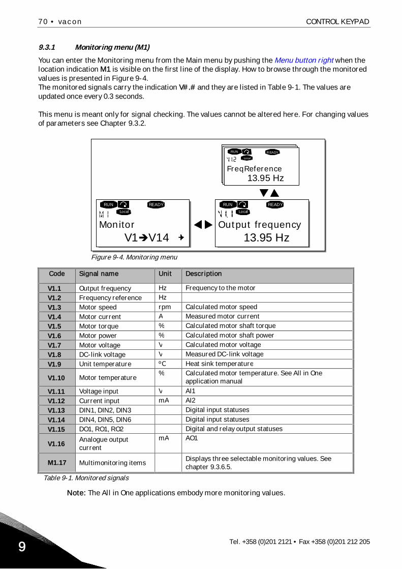
70 • vacon CONTROL KEYPAD
Tel. +358 (0)201 2121 • Fax +358 (0)201 212 2059
9.3.1 Monitoring menu (M1)
You can enter the Monitoring menu from the Main menu by pushing the Menu button right when thelocation indication M1 is visible on the first line of the display. How to browse through the monitoredvalues is presented in Figure 9-4.The monitored signals carry the indication V#.# and they are listed in Table 9-1. The values areupdated once every 0.3 seconds.
This menu is meant only for signal checking. The values cannot be altered here. For changing valuesof parameters see Chapter 9.3.2.
Figure 9-4. Monitoring menu
Code Signal name Unit Description
V1.1 Output frequency Hz Frequency to the motorV1.2 Frequency reference HzV1.3 Motor speed rpm Calculated motor speedV1.4 Motor current A Measured motor currentV1.5 Motor torque % Calculated motor shaft torqueV1.6 Motor power % Calculated motor shaft powerV1.7 Motor voltage V Calculated motor voltageV1.8 DC-link voltage V Measured DC-link voltageV1.9 Unit temperature ºC Heat sink temperature
V1.10 Motor temperature% Calculated motor temperature. See All in One
application manual
V1.11 Voltage input V AI1V1.12 Current input mA AI2V1.13 DIN1, DIN2, DIN3 Digital input statusesV1.14 DIN4, DIN5, DIN6 Digital input statusesV1.15 DO1, RO1, RO2 Digital and relay output statuses
V1.16Analogue outputcurrent
mA AO1
M1.17 Multimonitoring itemsDisplays three selectable monitoring values. Seechapter 9.3.6.5.
Table 9-1. Monitored signals
Note: The All in One applications embody more monitoring values.
V1 V14
READYLocal
13.95 Hz
READYLocal
13.95 Hz
R EADYLoca l
RUN RUN
RUN
Monitor Output frequency
FreqReference

CONTROL KEYPAD vacon • 71
24-hour support: +358 (0)40 837 1150 • Email: [email protected] 9
9.3.2 Parameter menu (M2)
Parameters are the way of conveying the commands of the user to the frequency converter. Theparameter values can be edited by entering the Parameter Menu from the Main Menu when thelocation indication M2 is visible on the first line of the display. The value editing procedure ispresented in Figure 9-5.
Push the Menu button right once to move into the Parameter Group Menu (G#). Locate theparameter group desired by using the Browser buttons and push the Menu button right again toenter the group and its parameters. Use again the Browser buttons to find the parameter (P#) youwant to edit. From here you can proceed in two different ways: Pushing the Menu button right takesyou to the edit mode. As a sign of this, the parameter value starts to blink. You can now change thevalue in two different manners:
1 Just set the new desired value with the Browser buttons and confirm the change with theEnter button. Consequently, the blinking stops and the new value is visible in the value field.
2 Push the Menu button right once again. Now you will be able to edit the value digit by digit. Thisediting manner may come in handy, when a relatively greater or smaller value than that on thedisplay is desired. Confirm the change with the Enter button.
The value will not change unless the Enter button is pushed. Pressing the Menu button left takesyou back to the previous menu.
Several parameters are locked, i.e. uneditable, when the drive is in RUN status. If you try to changethe value of such a parameter the text *Locked* will appear on the display. The frequency convertermust be stopped in order to edit these parameters.The parameters values can also be locked using the function in menu M6 (see Chapter Parameterlock (P6.5.2)).
You can return to the Main menu anytime by pressing the Menu button left for 3 seconds.
The basic application package "All in One" includes seven applications with different sets ofparameters. See the All in One Application manual for closer information.
Once in the last parameter of a parameter group, you can move directly to the first parameter of thatgroup by pushing the Browser button up.
See the diagram for parameter value change procedure on page 72.
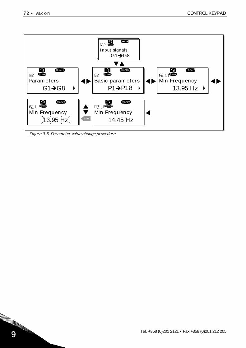
72 • vacon CONTROL KEYPAD
Tel. +358 (0)201 2121 • Fax +358 (0)201 212 2059
Figure 9-5. Parameter value change procedure
G1 G8
READY
Keypad
P1 P18
READY
Keypad
13.95 Hz
READY
Keypad
G1 G8
Keypad
READY
Keypad
13.95 Hz enter
READY
Keypad
14.45 Hz
Parameters Basic parameters Min Frequency
Input signals
Min Frequency Min Frequency

CONTROL KEYPAD vacon • 73
24-hour support: +358 (0)40 837 1150 • Email: [email protected] 9
9.3.3 Keypad control menu (M3)
In the Keypad Controls Menu, you can choose the control place, edit the frequency reference andchange the direction of the motor. Enter the submenu level with the Menu button right.
Code Parameter Min Max Unit Default Cust ID Note
P3.1 Control place 1 3 1 1251=I/O terminal2=Keypad3=Fieldbus
R3.2 Keypad reference Par.2.1.1 Par. 2.1.2 Hz
P3.3 Direction (on keypad) 0 1 0 123 0=Forward1=Reverse
R3.4 Stop button 0 1 1 114
0=Limited function of Stopbutton
1=Stop button alwaysenabled
Table 9-2. Keypad control parameters, M3
9.3.3.1 Selection of control place
There are three different places (sources) which the frequency converter can be controlled from. Foreach control place, a different symbol will appear on the alphanumeric display:
Control place Symbol
I/O terminals
Keypad (panel)
Fieldbus
Change the control place by entering the edit mode with the Menu button right. The options can thenbe browsed through with the Browser buttons. Select the desired control place with the Enterbutton. See the diagram on the next page. See also 9.3.3 above.
Figure 9-6. Selection of control place
I/O term
Keypad
Bus/Comm
P1 P4
READYI/Oterm
READYI/Oterm
READYI/Oterm
READYI/Oterm
enter
READY
Keypad
STOP STOP STOP
STOPSTOP
Keypad control Control PlaceI/O Remote
Control PlaceI/O Remote
Control PlaceKeypad
Control PlaceKeypad
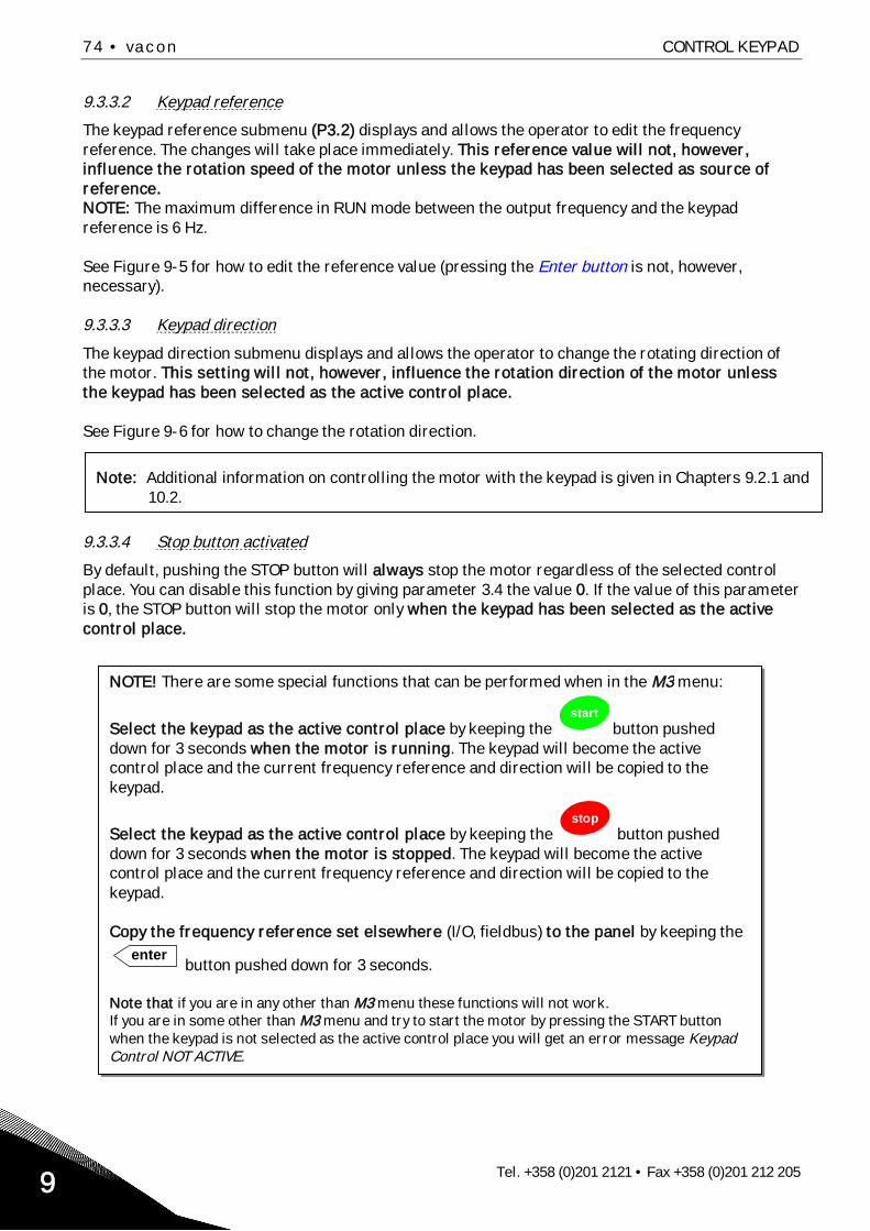
74 • vacon CONTROL KEYPAD
Tel. +358 (0)201 2121 • Fax +358 (0)201 212 2059
9.3.3.2 Keypad reference
The keypad reference submenu (P3.2) displays and allows the operator to edit the frequencyreference. The changes will take place immediately. This reference value will not, however,influence the rotation speed of the motor unless the keypad has been selected as source ofreference.NOTE: The maximum difference in RUN mode between the output frequency and the keypadreference is 6 Hz.
See Figure 9-5 for how to edit the reference value (pressing the Enter button is not, however,necessary).
9.3.3.3 Keypad direction
The keypad direction submenu displays and allows the operator to change the rotating direction ofthe motor. This setting will not, however, influence the rotation direction of the motor unlessthe keypad has been selected as the active control place.
See Figure 9-6 for how to change the rotation direction.
9.3.3.4 Stop button activated
By default, pushing the STOP button will always stop the motor regardless of the selected controlplace. You can disable this function by giving parameter 3.4 the value 0. If the value of this parameteris 0, the STOP button will stop the motor only when the keypad has been selected as the activecontrol place.
Note: Additional information on controlling the motor with the keypad is given in Chapters 9.2.1 and10.2.
NOTE! There are some special functions that can be performed when in the M3 menu:
Select the keypad as the active control place by keeping thestart
button pusheddown for 3 seconds when the motor is running. The keypad will become the activecontrol place and the current frequency reference and direction will be copied to thekeypad.
Select the keypad as the active control place by keeping thestop
button pusheddown for 3 seconds when the motor is stopped. The keypad will become the activecontrol place and the current frequency reference and direction will be copied to thekeypad.
Copy the frequency reference set elsewhere (I/O, fieldbus) to the panel by keeping theenter
button pushed down for 3 seconds.
Note that if you are in any other than M3 menu these functions will not work.If you are in some other than M3 menu and try to start the motor by pressing the START buttonwhen the keypad is not selected as the active control place you will get an error message KeypadControl NOT ACTIVE.

CONTROL KEYPAD vacon • 75
24-hour support: +358 (0)40 837 1150 • Email: [email protected] 9
9.3.4 Active faults menu (M4)
The Active faults menu can be entered from the Main menu by pushing the Menu button right whenthe location indication M4 is visible on the first line of the keypad display.
When a fault brings the frequency converter to a stop, the location indication F1, the fault code, ashort description of the fault and the fault type symbol (see Chapter 9.3.4.1) will appear on the dis-play. In addition, the indication FAULT or ALARM (see Figure 9-1 or Chapter 9.1.1) is displayed and,in case of a FAULT, the red led on the keypad starts to blink. If several faults occur simultaneously,the list of active faults can be browsed with the Browser buttons.
Find the fault codes in chapter 11.2, Table 11-2.
The memory of active faults can store the maximum of 10 faults in the order of appearance. Thedisplay can be cleared with the Reset button and the read-out will return to the same state it wasbefore the fault trip. The fault remains active until it is cleared with the Reset button or with a resetsignal from the I/O terminal or fieldbus.
Note! Remove external Start signal before resetting the fault to prevent unintentional restart of thedrive.
Normal state,no faults:
9.3.4.1 Fault types
In the NX frequency converter, there are four different types of faults. These types differ from eachother on the basis of the subsequent behaviour of the drive. See Table 9-3.
Figure 9-7. Fault display
F0
READY
I/Oterm
Active faults
Fault typesymbol F T1 T13
STOP FAULTI/Oterm
STOPI/Oterm
FAULT
34:21:05
I/Oterm
17 11 Output phase Operations days
Operation hours

76 • vacon CONTROL KEYPAD
Tel. +358 (0)201 2121 • Fax +358 (0)201 212 2059
Fault type symbol MeaningA
(Alarm)This type of fault is a sign of an unusual operatingcondition. It does not cause the drive to stop, nor does itrequire any special actions. The 'A fault' remains in thedisplay for about 30 seconds.
F(Fault)
An 'F fault' is a kind of fault that makes the drive stop.Actions need to be taken in order to restart the drive.
AR(Fault Autoreset)
If an 'AR fault' occurs the drive will also stopimmediately. The fault is reset automatically and thedrive tries to restart the motor. Finally, if the restart isnot successful, a fault trip (FT, see below) occurs.
FT(Fault Trip)
If the drive is unable to restart the motor after an ARfault an FT fault occurs. The effect of the 'FT fault' isbasically the same as that of the F fault: the drive isstopped.
Table 9-3. Fault types
9.3.4.2 Fault time data record
When a fault occurs the information described above in 9.3.4 is displayed. By pushing the Menubutton right here you will enter the Fault time data record menu indicated by T.1 T.13. In thismenu, some selected important data valid at the time of the fault are recorded. This feature isintended to help the user or the service person to determine the cause of fault.
The data available are:
T.1 Counted operation days(Fault 43: Additional code)
d
T.2 Counted operation hours(Fault 43: Counted operation days)
hh:mm:ss(d)
T.3 Output frequency(Fault 43: Counted operation hours)
Hz(hh:mm:ss)
T.4 Motor current AT.5 Motor voltage VT.6 Motor power %T.7 Motor torque %T.8 DC voltage VT.9 Unit temperature C
T.10 Run statusT.11 DirectionT.12 WarningsT.13 0-speed*
Table 9-4. Fault time recorded data
* Tells the user if the drive was at zero speed (< 0.01 Hz) when the fault occurred
9.3.4.3 Real time record
If real time is set to run on the frequency converter the data items T1 and T2 will appear as follows:
T.1 Counted operation days yyyy-mm-ddT.2 Counted operation hours hh:mm:ss,sss

CONTROL KEYPAD vacon • 77
24-hour support: +358 (0)40 837 1150 • Email: [email protected] 9
9.3.5 Fault history menu (M5)
The Fault history menu can be entered from the Main menu by pushing the Menu button right whenthe location indication M5 is visible on the first line of the keypad display. Find the fault codes inTable 11-2.
All faults are stored in the Fault history menu in which you can browse through them using theBrowser buttons. Additionally, the Fault time data record pages (see Chapter 9.3.4.2) are accessibleat each fault. You can return to the previous menu anytime by pushing the Menu button left.
The memory of the frequency converter can store a maximum of 30 faults in the order ofappearance. The number of faults currently in the fault history is shown on the value line of the mainpage (H1 H#). The order of the faults is indicated by the location indication in the upper left cornerof the display. The latest fault carries the indication F5.1, the second latest F5.2 etc. If there are 30uncleared faults in the memory the next occurring fault will erase the oldest from the memory.
Pressing the Enter button for about 2 to 3 seconds resets the whole fault history. Then, the symbolH# will change to 0.
Figure 9-8. Fault history menu
H1 H3
READYI/Oterm
T1 T7
I/Oterm
READY
I/Oterm
I/Oterm
READY
13:25:43
I/Oterm
enter
17Fault history 11 Output phase
5 ChargeSwitch
Operation days
Operation hours
PUSH to reset

78 • vacon CONTROL KEYPAD
Tel. +358 (0)201 2121 • Fax +358 (0)201 212 2059
9.3.6 System menu (M6)
The System menu can be entered from the main menu by pushing the Menu button right when thelocation indication M6 is visible on the display.
The controls associated with the general use of the frequency converter, such as applicationselection, customised parameter sets or information about the hardware and software are locatedunder the System menu. The number of submenus and subpages is shown with the symbol S (or P)on the value line.
Functions in the System menu
Code Function Min Max Unit Default Cust Selections
S6.1 Languageselection English Available selections depend
on the language package.
S6.2 Applicationselection
BasicApplication
Basic ApplicationStandard ApplicationLocal/Remote control Appl.Multi-Step ApplicationPID Control ApplicationMulti-Purpose Control Appl.Pump and Fan Control Appl.
S6.3 Copy parameters
S6.3.1 Parameter sets
Store set 1Load set 1Store set 2Load set 2Load factory defaults
S6.3.2 Load up to keypad All parameters
S6.3.3 Load down fromkeypad
All parametersAll but motor parametersApplication parameters
P6.3.4 Parameter backup Yes YesNo
S6.4 Compareparameters
S6.4.1 Set1 Not usedS6.4.2 Set2 Not usedS6.4.3 Factory settingsS6.4.4 Keypad setS6.5 Security
S6.5.1 Password Not used 0=Not used
P6.5.2 Parameter lock ChangeEnabled
Change EnabledChange Disabled
S6.5.3 Start-up wizard NoYes
S6.5.4 Multimonitoringitems
Change EnabledChange Disabled
S6.6 Keypad settingsP6.6.1 Default page
P6.6.2 Default page/Operating menu
P6.6.3 Timeout time 0 65535 s 30P6.6.4 Contrast 0 31 18P6.6.5 Backlight time Always 65535 min 10S6.7 Hardware settings
P6.7.1 Internal brakeresistor Connected Not connected
Connected
P6.7.2 Fan control Continuous ContinuousTemperature

CONTROL KEYPAD vacon • 79
24-hour support: +358 (0)40 837 1150 • Email: [email protected] 9
P6.7.3 HMI acknowledg.timeout 200 5000 ms 200
P6.7.4 HMI number ofretries 1 10 5
S6.8 Systeminformation
S6.8.1 Total countersC6.8.1.1 MWh counter kWh
C6.8.1.2 Power On daycounter
C6.8.1.3 Power On hourscounter hh:mm:ss
S6.8.2 Trip countersT6.8.2.1 MWh counter kWh
T6.8.2.2 ClearMWh trip counter
T6.8.2.3 Operating daystrip counter
T6.8.2.4 Operating hourstrip counter hh:mm:ss
T6.8.2.5 Clear operating timecounter
S6.8.3 Software infoS6.8.3.1 Software package
S6.8.3.2 System softwareversion
S6.8.3.3 Firmware interfaceS6.8.3.4 System loadS6.8.4 Applications
S6.8.4.# Name of applicationD6.8.4.#.1 Application ID
D6.8.4.#.2 Applications:Version
D6.8.4.#.3 Applications:Firmware interface
S6.8.5 Hardware
I6.8.5.1 Info: Power unittype code
I6.8.5.2 Info: Unit voltage VI6.8.5.3 Info: Brake chopperI6.8.5.4 Info: Brake resistorS6.8.6 Expander boards
S6.8.7 Debug menuFor Application program-ming only. Contact factoryfor more details
Table 9-5. System menu functions

80 • vacon CONTROL KEYPAD
Tel. +358 (0)201 2121 • Fax +358 (0)201 212 2059
9.3.6.1 Language selection
The Vacon control keypad offers you the possibility to control the frequency converter through thekeypad in the language of your choice.
Locate the language selection page under the System menu. Its location indication is S6.1. Press theMenu button right once to enter the edit mode. As the name of the language starts to blink you areable to choose another language for the keypad texts. Confirm the selection by pushing the Enterbutton The blinking stops and all textual information on the keypad is presented in the language youchose.
You can return to the previous menu anytime by pushing the Menu button left.
Figure 9-9. Selection of language
9.3.6.2 Application selection
The user can select the application desired by entering the Application selection page (S6.2). This isdone by pushing the Menu button right when on the first page of the System menu. Change then theapplication by pushing the Menu button right once again. The name of the application starts to blink.Now you can browse through the applications with the Browser buttons and select anotherapplication with the Enter button.
Changing application will reset all parameters. After application change, you will be asked if youwant the parameters of the new application to be uploaded to the keypad. If you wish this to happenpush the Enter button Pushing any other button leaves the parameters of the previously usedapplication saved in the keypad. For more information, see Chapter 9.3.6.3.
For more information about the Application Package, see Vacon NX Application Manual.
System MenuS1 S11
READYI/Oterm
LanguageEnglish
READYI/Oterm
LanguageEnglish
READYI/Oterm
enter
READYI/Oterm
FrancaisLangue

CONTROL KEYPAD vacon • 81
24-hour support: +358 (0)40 837 1150 • Email: [email protected] 9
Figure 9-10. Change of application
9.3.6.3 Copy parameters
The parameter copy function is used when the operator wants to copy one or all parameter groupsfrom one drive to another or to store parameter sets in the internal memory of the converter. All theparameter groups are first uploaded to the keypad, then the keypad is connected to another driveand then the parameter groups are downloaded to it (or possibly back to the same drive).
Before any parameters can successfully be copied from one drive to another the drive has to bestopped when the parameters are downloaded to it:
The parameter copy menu (S6.3) embodies four functions:
Parameter sets (S6.3.1)
The Vacon NX frequency converter features a possibility for the user to load back the factory defaultparameter values and to store and load two customised parameter sets (all parameters included inthe application).
On Parameter sets page (S6.3.1), push the Menu button right to enter the Edit menu. The textLoadFactDef begins to blink and you can confirm the loading of factory defaults by pushing the Enterbutton. The drive resets automatically.Alternatively you can choose any other of the storing or loading functions with the Browser buttons.Confirm with the Enter button. Wait until 'OK' appears on the display.
S1 S11
STOP READY
I/Oterm
STOP READY
I/Oterm
STOP READYI/Oterm
enter
STOP READYI/Oterm
System Menu ApplicationStandard
ApplicationStandard
ApplicationMulti-step

82 • vacon CONTROL KEYPAD
Tel. +358 (0)201 2121 • Fax +358 (0)201 212 2059
Figure 9-11. Storing and loading of parameter sets
Upload parameters to keypad (To keypad, S6.3.2)
This function uploads all existing parameter groups to the keypad provided that the drive is stopped.
Enter the To keypad page (S6.3.2) from the Parameter copy menu. Push the Menu button right toenter the edit mode. Use the Browser buttons to select the option All parameters and press theEnter button. Wait until 'OK' appears on the display.
Figure 9-12. Parameter copy to keypad
Download parameters to drive (From keypad, S6.3.3)
This function downloads one or all parameter groups uploaded to the keypad to a drive providedthat the drive is in STOP status.
Enter the From keypad page (S6.3.3) from the Parameter copy menu. Push the Menu button right toenter the edit mode. Use the Browser buttons to select either the option All parameters orApplication parameters and press the Enter button. Wait until 'OK' appears on the display.
The procedure to download the parameters from keypad to drive is similar to that of from drive tokeypad. See above.
READY READY enter
READY READY
OK
Parameter setsSelect
Parameter setsCANCEL
CONFIRM
Parameter setsWait...
Parameter sets
LoadFactDef
P1 P4
READY READY READY
enter
READY READY
Copy Parameters Up to keypad Up to keypadSelect CANCEL
CONFIRM
Up to keypadWait...
Up to keypadOK
All param.CHANGE VALUE
CONTROL KEYPAD vacon • 83
24-hour support: +358 (0)40 837 1150 • Email: [email protected] 9
Automatic parameter backup (P6.3.4)
On this page you can activate or inactivate the parameter backup function. Enter the edit mode bypressing the Menu button right. Choose Yes or No with the Browser buttons.
When the Parameter backup function is activated Vacon NX control keypad makes a copy of theparameters of the presently used application. Every time a parameter is changed the keypad backupis automatically updated.
When applications are changed, you will be asked if you wish the parameters of the new applicationto be uploaded to the keypad. For this to happen, push the Enter button. If you wish to keep the copyof the parameters of the previously used application saved in the keypad push any other button.Now you will be able to download these parameters to the drive following the instructions given inchapter 9.3.6.3.
If you want the parameters of the new application to be automatically uploaded to the keypad youhave to do this for the parameters of the new application once on page 6.3.2 as instructed.Otherwise the panel will always ask for the permission to upload the parameters.
Note: Parameters saved in the parameter settings on page S6.3.1 will be deleted when applicationsare changed. If you want to transfer the parameters from one application to another you have toupload them first to the keypad.
9.3.6.4 Parameter comparison
In the Parameter comparison submenu (S6.4), you can compare the actual parameter values to thevalues of your customised parameter sets and those loaded to the control keypad.
The comparison is performed by pushing the Menu button right when in the Compare parameterssubmenu. The actual parameter values are first compared to those of the customised parameterSet1. If no differences are detected a '0' is displayed on the lowermost line. But if any of theparameter values differ from those of the Set1 the number of the deviations is displayed togetherwith symbol P (e.g. P1 P5 = five deviating values). By pressing the Menu button right once again youcan still enter the pages where you can see both the actual value and the value it was compared to.In this display, the value on the Description line (in the middle) is the default value and the one onthe value line (lowermost) is the edited value. Furthermore, you can also edit the actual value withthe Browser buttons in the edit mode that you can reach by pushing the Menu button right onceagain.In the same way, you can perform the comparison of the actual values to Set2, Factory Settings andKeypad Set.

84 • vacon CONTROL KEYPAD
Tel. +358 (0)201 2121 • Fax +358 (0)201 212 2059
Figure 9-13. Parameter comparison
9.3.6.5 Security
NOTE: The Security submenu is protected with a password. Store the password in a safe place!
Password (S6.5.1)
The application selection can be protected against unauthorised changes with the Password function(S6.5.1).By default, the password function is not in use. If you want to activate the function, enter the editmode by pushing the Menu button right. A blinking zero appears in the display and now you can set apassword with the Browser buttons. The password can be any number between 1 and 65535.
Note that you can also set the password by digits. In the edit mode, push the Menu button right onceagain and another zero appears on the display. Now set first the units. Then push the Menu buttonleft and you can set the tens etc. Finally, confirm the password setting with the Enter button. Afterthis, you have to wait until the Timeout time (P6.6.3) (see page 87) has expired before the passwordfunction is activated.If you now try to change applications or the password itself you will be prompted for the currentpassword. The password will be entered with the Browser buttons.Deactivate the password function by entering the value 0.
Figure 9-14. Password setting
Note! Store the password in a secure location! No changes can be made unless a valid password isentered!
C1 C3
READY READY
READY
0
enter
P1 P6P2.1.2= 50.0
READY
20.0 Hz
P2.1.2= 50.0
READY
20.0 Hz
ParamComparison Set1
Set1
CONFIRM CHANGE
EDIT VALUE
OR
READY
I/Oterm
0
READY
I/Oterm enter
00
READY
I/Oterm enter
PasswordNot in use
Password PasswordOR:

CONTROL KEYPAD vacon • 85
24-hour support: +358 (0)40 837 1150 • Email: [email protected] 9
Parameter lock (P6.5.2)
This function allows the user to prohibit changes to the parameters.
If the parameter lock is activated the text *locked* will appear on the display if you try to edit aparameter value.
NOTE: This function does not prevent unauthorised editing of parameter values.
Enter the edit mode by pushing the Menu button right. Use the Browser buttons to change theparameter lock status. Accept the change with the Enter button or return to the previous level withthe Menu button left.
Figure 9-15. Parameter locking
Start-up Wizard (P6.5.3)
The Start-up Wizard is a feature on the control keypad to facilitate the commissioning of the fre-quency converter. If selected active (default), the Start-up Wizard prompts the operator for the lan-guage and application of his/her choice plus for the values for a set of parameters common to allapplications as well as for a set of application-dependent parameters.
Always accept the value with the Enter button, scroll options or change values with the Browserbuttons (up and down arrows).
Set the Start-up Wizard active in the following way: In the System Menu, find page P6.5.3. Press theMenu button right once to reach the edit mode. Use the Browser buttons to set value Yes andconfirm the selection with the Enter button. If you want to deactivate the function follow the sameprocedure and give the parameter value No.
Figure 9-16. Activation of Start-up wizard
S1 S9
READY
I/Oterm
READYI/Oterm
READY
I/Oterm
enter
READY
I/Oterm
READYI/Oterm
P1 P4System Menu Security
Parameter Lock
ChangeEnable
Parameter LockChangeDisabl
Parameter Lock
ChangeEnable
READY
I/Oterm
READY
I/Oterm
READY
I/Otermenter
Startup wizard Startup wizardNo No
Startup wizardYes
CANCEL
CONFIRM
READY
I/Oterm
READY
I/Oterm
READY
I/Otermenter
Startup wizard Startup wizardNo No
Startup wizardYes
CANCEL
CONFIRM

86 • vacon CONTROL KEYPAD
Tel. +358 (0)201 2121 • Fax +358 (0)201 212 2059
Multimonitoring items (P6.5.4)
Vacon alpha-numeric keypad features a display where you can monitor even three actual values atthe same time (see chapter 9.3.1 and chapter Monitoring values in the manual of the application youare using). On page P6.5.4 of the System Menu you can define if it is possible for the operator toreplace the values monitored with other values. See below.
Figure 9-17. Enabling the change of multimonitoring items
9.3.6.6 Keypad settings
In the Keypad settings submenu under the System menu you can further customise your frequencyconverter operator interface.Locate the Keypad settings submenu (S6.6). Under the submenu, there are four pages (P#)associated with the keypad operation:
Figure 9-18. Keypad settings submenu
Default page (P6.6.1)
Here you can set the location (page) to which the display automatically moves as the Timeout time(see below) has expired or as the power is switched on to the keypad.
If the Default Page value is 0 the function is not activated, i.e. the last displayed page remains on thekeypad display. Press the Menu button right once to enter the edit mode. Change the number of theMain menu with the Browser buttons. Pressing the Menu button right once again makes you able toedit the number of the submenu/page. If the page you want to move to by default is at the third levelrepeat the procedure. Confirm the new default page value with the Enter button. You can return tothe previous step anytime by pushing the Menu button left.
Figure 9-19. Default page function
0.
READY
I/Oterm
READY
I/Oterm
READY
I/Oterm
0. 1.
enter
Default page REPEAT TO SETDEFAULT SUBMENU/PAGECANCEL
Default pageDefault pageCONFIRM CHANGE
READYI/Oterm
READYI/Oterm
enter
READYI/Oterm
Multimon. items
ChangeEnableMultimon. items Multimon. items
ChangeEnable ChangeDisable
P1 P5
READYI/Oterm
0.
READYI/Oterm
Keypad settings Default page

CONTROL KEYPAD vacon • 87
24-hour support: +358 (0)40 837 1150 • Email: [email protected] 9
Default page in the operating menu (P6.6.2)
Here you can set the location (page) in the Operating menu (in special applications only) to whichthe display automatically moves as the set Timeout time (see below) has expired or as the power isswitched on to the keypad. See setting of Default page above.
Timeout time (P6.6.3)
The Timeout time setting defines the time after which the keypad display returns to the Default page(P6.6.1) see above.Move to the Edit menu by pressing the Menu button right. Set the timeout time you want and confirmthe change with the Enter button. You can return to the previous step anytime by pushing the Menubutton left.
Figure 9-20. Timeout time setting
Note: If the Default page value is 0 the Timeout time setting has no effect.
Contrast adjustment (P6.6.4)
In case the display is unclear you can adjust its contrast through the same procedure as that for thetimeout time setting (see above).
Backlight time (P6.6.5)
Giving a value for the Backlight time, you can determine how long the backlight stays on beforegoing out. You can select here any time between 1 and 65535 minutes or 'Forever'. For the valuesetting procedure see Timeout time (P6.6.3).
9.3.6.7 Hardware settings
NOTE: The Hardware settings submenu is protected with a password (see chapter Password(S6.5.1). Store the password in a safe place!
In the Hardware settings submenu (S6.7) under the System menu you can further control somefunctions of the hardware in your frequency converter. The functions available in this menu areInternal brake resistor connection, Fan control, HMI acknowledge timeout and HMI retry.
Internal brake resistor connection (P6.7.1)
With this function you can tell the frequency converter, whether the internal brake resistor isconnected or not. If you have ordered the frequency converter with an internal brake resistor, thedefault value of this parameter is Connected. However, if it is necessary to increase braking capacityby installing an external brake resistor, or if the internal brake resistor is disconnected for anotherreason, it is advisable to change the value of this function to Not conn. in order to avoid unnecessaryfault trips.
Enter the edit mode by pushing the Menu button right. Use the Browser buttons to change theinternal brake resistor status. Accept the change with the Enter button or return to the previouslevel with the Menu button left.
90 s
READY READY READY
90 s.
enter
60 s.Timeout time Timeout time Timeout time
CANCEL
CONFIRM CHANGE

88 • vacon CONTROL KEYPAD
Tel. +358 (0)201 2121 • Fax +358 (0)201 212 2059
Note! The brake resistor is available as optional equipment for all classes. It can be installedinternally in classes FR4 to FR6.
Figure 9-21. Internal brake resistor connection
Fan control (P6.7.2)
This function allows you to control the frequency converter’s cooling fan. You can set the fan to runcontinuously when the power is switched on or depending on the temperature of the unit. If the latterfunction has been selected the fan is switched on automatically when the heat sink temperaturereaches 60 C or the converter is in RUN state. The fan receives a stop command when the heat sinktemperature falls to 55 C and the converter is in STOP state. However, the fan runs for about aminute after receiving the stop command or switching on the power, as well as after changing thevalue from Continuous to Temperature.
Note! The fan runs always when the drive is in RUN state.
Enter the edit mode by pushing the Menu button right. The present mode shown starts to blink. Usethe Browser buttons to change the fan mode. Accept the change with the Enter button or return tothe previous level with the Menu button left.
Figure 9-22. Fan control function
HMI acknowledge timeout (P6.7.3)
This function allows the user to change the timeout of the HMI acknowledgement time in caseswhere there is an additional delay in the RS-232 transmission due to use of modems for commu-nication over longer distances, for example.
Note! If the frequency converter has been connected to the PC with a normal cable, the defaultvalues of parametres 6.7.3 and 6.7.4 (200 and 5) must not be changed.If the frequency converter has been connected to the PC via a modem and there is delay intransferring messages, the value of par. 6.7.3 must be set according to the delay as follows:
S1 S8
READY
I/Oterm
READY
I/Oterm
READYI/Oterm
enter
READYI/Oterm
READY
I/Oterm
P1 P4System Menu HW settings
InternBrakeRes
Connected
Not conn.
InternBrakeRes
ConnectedInternBrakeRes
READY
I/Oterm
READY
I/Oterm
enter
READY
I/O term
Fan controlContinuous
Fan control Fan controlContinuous Temperature

CONTROL KEYPAD vacon • 89
24-hour support: +358 (0)40 837 1150 • Email: [email protected] 9
Example:Transfer delay between the frequency converter and the PC = 600 msThe value of par. 6.7.3 is set to 1200 ms (2 x 600, sending delay + receivingdelay)The corresponding setting shall be entered in the Misc -part of the fileNCDrive.ini:
Retries = 5AckTimeOut = 1200TimeOut = 6000
It must also be considered that intervals shorter than the AckTimeOut-time cannot be used in NC-Drive monitoring.
Enter the edit mode by pushing the Menu button right. Use the Browser buttons to change theacknowledgement time. Accept the change with the Enter button or return to the previous level withthe Menu button left.
Figure 9-23. HMI acknowledge timeout
Number of retries to receive HMI acknowledgement (P6.7.4)
With this parameter you can set the number of times the drive will try receive acknowledgement ifthis does not succeed within the acknowledgement time (P6.7.3) or if the received acknowledgementis faulty.
Enter the edit mode by pushing the Menu button right. The present value shown starts to blink. Usethe Browser buttons to change the amount of retries. Accept the change with the Enter button orreturn to the previous level with the Menu button left.
See Figure 9-23 for the procedure of changing the value.
9.3.6.8 System info
In the System info submenu (S6.8) you can find frequency converter-related hardware and softwareinformation as well as operation-related information.
Total counters (S6.8.1)
In the Total counters page (S6.8.1) you can find information related to the frequency converteroperation times, i.e. the total numbers of MWh, operation days and operation hours passed so far.Unlike the counters in the Trip counters , these counters cannot be reset.
Note! The Power On time counter (days and hours) runs always, when the power is on.
Page Counter ExampleC6.8.1.1. MWh counterC6.8.1.2. Power On day counter Value on display is 1.013. The drive has operated
for 1 year and 13 days.C6.8.1.3. Power On hour counter Value on display is 7:05:16. The drive has
operated for 7 hours 5 minutes and 16 seconds.Table 9-6. Counter pages
READY
I/Oterm
200ms
READY
I/Oterm
enter
200msHMI ACK timeout HMI ACK timeout

90 • vacon CONTROL KEYPAD
Tel. +358 (0)201 2121 • Fax +358 (0)201 212 2059
Trip counters (S6.8.2)
Trip counters (menu S6.8.2) are counters the values of which can be reset i.e. restored to zero. Youhave the following resettable counters at your disposal. See Table 9-6 for examples.
Note! The trip counters run only when the motor is running.
Page CounterT6.8.2.1 MWh counterT6.8.2.3 Operation day counterT6.8.2.4 Operation hour counter
Table 9-7. Resettable counters
The counters can be reset on pages 6.8.2.2 (Clear MWh counter) and 6.8.2.5 (Clear Operation timecounter).Example: When you want to reset the operation counters you should do the following:
Figure 9-24. Counter reset
Software (S6.8.3)
The Software information page includes information on the following frequency converter softwarerelated topics:
Page Content6.8.3.1 Software package6.8.3.2 System software version6.8.3.3 Firmware interface6.8.3.4 System load
Table 9-8. Software information pages
T1 T5
READY READY READY
enter
READY READY
STOP STOP
STOP STOP READYSTOP
Trip counters Clr Optime cntr Clr Optime cntrNot reset Not reset
Clr Optime cntrReset
Clr Optime cntrReset
Clr Optime cntrNot reset

CONTROL KEYPAD vacon • 91
24-hour support: +358 (0)40 837 1150 • Email: [email protected] 9
Applications (S6.8.4)
At location S6.8.4 you can find the Applications submenu containing information about not only theapplication currently in use but also all other applications loaded into the frequency converter. Theinformation available is:
Page Content6.8.4.# Name of application6.8.4.#.1 Application ID6.8.4.#.2 Version6.8.4.#.3 Firmware interface
Table 9-9. Applications information pages
Figure 9-25. Applications info page
In the Applications information page, push the Menu button right to enter the Application pages ofwhich there are as many as there are applications loaded into the frequency converter. Locate theapplication you want information about with the Browser buttons and then enter the Informationpages with the Menu button right. Use again the Browser buttons to see the different pages.
Hardware (S6.8.5)
The Hardware information page provides information on the following hardware-related topics:
Page Content6.8.5.1 Nominal power of the unit6.8.5.2 Nominal voltage of the unit6.8.5.3 Brake chopper6.8.5.4 Brake resistor
Table 9-10. Hardware information pages
Expander boards (S6.8.6)
In the Expander boards pages you find information about the basic and option boards connected tothe control board (see Chapter 8.2).
You can check the status of each board slot by entering the Expander boards page with the Menubutton right and using the Browser buttons to choose the board whose status you wish to check.Push the Menu button right again to display the status of the board. The keypad will also display theprogram version of the respective board when you push either one of the Browser buttons.If no board is connected to the slot the text 'no board' will be shown. If a board is connected to a slotbut the connection is somehow lost the text 'no conn.' is displayed. See Chapter 8.2 and Figure 8-1and 6-16 for more information.
A1 A7
I/Oterm I/Oterm
D1 D3
I/Oterm
READY READY
D1 D3
I/Oterm
READY
NXFIFF01
2.01
I/Oterm
Applications Basic
Standard
Application id
Version

92 • vacon CONTROL KEYPAD
Tel. +358 (0)201 2121 • Fax +358 (0)201 212 2059
For more information on the expander board-related parameters, see Chapter 9.3.7.
Figure 9-26. Expander board information menus
Debug menu (S6.8.7)
This menu is meant for advanced users and application designers. Contact factory for any assistanceneeded.
E1 E5
READYI/Oterm
A:NXOPTA1
I/Oterm
READY
B:NXOPTA2
I/Oterm
E1 E2
I/Oterm
READY
I/Oterm
E1 E2 10001.0
Expander boards
Software version
StateRun

CONTROL KEYPAD vacon • 93
24-hour support: +358 (0)40 837 1150 • Email: [email protected] 9
9.3.7 Expander board menu (M7)
The Expander board menu makes it possible for the user 1) to see what expander boards areconnected to the control board and 2) to reach and edit the parameters associated with the expanderboard.Enter the following menu level (G#) with the Menu button right. At this level, you can browsethrough slots (see page 56) A to E with the Browser buttons to see what expander boards areconnected. On the lowermost line of the display you also see the number of parameters associatedwith the board. You can view and edit the parameter values in the same way as described in chapter9.3.2. See Table 9-11 and Figure 9-27.
Expander board parameters
Code Parameter Min Max Default Cust Selections
P7.1.1.1 AI1 mode 1 5 3
1=0…20 mA2=4…20 mA3=0…10 V4=2…10 V5=–10…+10 V
P7.1.1.2 AI2 mode 1 5 1 See P7.1.1.1
P7.1.1.3 AO1 mode 1 4 1
1=0…20 mA2=4…20 mA3=0…10 V4=2…10 V
Table 9-11. Expander board parameters (board OPT-A1)
Figure 9-27. Expander board information menu
9.4 Further keypad functions
The Vacon NX control keypad embodies additional application-related functions. See Vacon NXApplication Package for more information.
G1 G5
READY READY
G1 G2
READY
READY
enter
P1 P4
REA DYI/Oterm
G1 G2
REA DYI/Oterm
V1 V2
READY
REA DYI/Oterm
D:NXOPTC2
C:NXOPTC1Expander boards Parameters
Slave address126
Slave address126
Baud rate
Auto
Monitor
CHANGE VALUE
CONFIRM CHANGE

94 • vacon COMMISSIONING
Tel. +358 (0)201 2121 • Fax +358 (0)201 212 20510
10. COMMISSIONING
10.1 Safety
Before commissioning, note the following directions and warnings:
1 Internal components and circuit boards of the frequency converter (ex-cept for the galvanically isolated I/O terminals) are live when Vacon NX isconnected to mains potential. Coming into contact with this voltage isextremely dangerous and may cause death or severe injury.
2 The motor terminals U, V, W and the DC-link/brake resistor terminals –/+are live when Vacon NX is connected to mains, even if the motor is notrunning.
3 The control I/O-terminals are isolated from the mains potential. How-ever, the relay outputs and other I/O-terminals may have a dangerouscontrol voltage present even when Vacon NX is disconnected from mains.
4 Do not make any connections with the frequency converter connected tothe mains.
5 After having disconnected the frequency converter from the mains, waituntil the fan stops and the indicators on the keypad go out (if no keypad isattached see the indicator through the keypad base). Wait 5 more min-utes before doing any work on Vacon NX connections. Do not even openthe cabinet door or cover before this time has expired.
6 Before connecting the frequency converter to mains make sure that theVacon NX front cover is closed.
10.2 Commissioning of the frequency converter
1 Read carefully the safety instructions in Chapter 1 and above and follow them.
2 After the installation, pay attention to:
- that both the frequency converter and the motor are grounded.
- that the mains and motor cables comply with the requirements given in Chapter 6.2.4.
- that the control cables are located as far as possible from the power cables (seeChapter 7, step 3) , the shields of the shielded cables are connected to protective earth
. The wires may not touch the electrical components of the frequency converter.
- that the common inputs of digital input groups are connected to +24V or ground of theI/O terminal or the external supply.
3 Check the quality and quantity of cooling air (chapter 5.2 and Table 5-4).
4 Check the inside of the frequency converter for condensation.
5 Check that all Start/Stop switches connected to the I/O terminals are in Stop-position.
6 Connect the frequency converter to mains.

COMMISSIONING vacon • 95
24-hour support: +358 (0)40 837 1150 • Email: [email protected] 10
7 Set the parameters of group 1 (See Vacon All in One Application Manual) according to therequirements of your application. At least the following parameters should be set:
- motor nominal voltage- motor nominal frequency- motor nominal speed- motor nominal current
You will find the values needed for the parameters on the motor rating plate.
8 Perform run test without motor
Perform either Test A or Test B:
A Controls from the I/O terminals:
a) Turn the Start/Stop switch to ON position.
b) Change the frequency reference
c) Check in the Monitoring menu M1 that the value of Output frequency changesaccording to the change of frequency reference.
d) Turn the Start/Stop switch to OFF position.
B Control from the control keypad:
a) Change the control from the I/O terminals to the keypad as advised in Chapter 9.3.3.1.
b) Push the Start button on the keypadstart
.
c) Move over to the Keypad control menu (M3) and Keypad Reference submenu (Chapter9.3.3.2) and change the frequency reference using the Browser buttons
+-
.
d) Check in the Monitoring menu M1 that the value of Output frequency changesaccording to the change of frequency reference.
e) Push the Stop button on the keypadstop
.
9 Run the start-up tests without the motor being connected to the process, if possible. If thisis not possible, secure the safety of each test prior to running it. Inform your co-workers ofthe tests.
a) Switch off the supply voltage and wait up until the drive has stopped as advised atChapter 10.1, step 5.
b) Connect the motor cable to the motor and to the motor cable terminals of thefrequency converter.
c) See to that all Start/Stop switches are in Stop positions.
d) Switch the mains ON
e) Repeat test 8A or 8B.
96 • vacon
Tel. +358 (0)201 2121 • Fax +358 (0)201 212 20510
10 Connect the motor to the process (if the startup test was run without the motor beingconnected)
a) Before running the tests, make sure that this can be done safely.
b) Inform your co-workers of the tests.
c) Repeat test 8A or 8B.

FAULT TRACING vacon • 97
24-hour support: +358 (0)40 837 1150 • Email: [email protected] 11
11. FAULT TRACING
The fault codes, their causes and correcting actions are presented in Table 11-2 below. Theconverter has an internal memory for storing the converter status at the time of fault as well asadditional information about the source of the fault. This feature is intended to help the user or theservice personnel to determine the cause of fault.
11.1 Fault time data record
When a fault occurs a fault code is displayed on the keypad. By pushing the Menu button right hereyou will enter the Fault time data record menu indicated by T.1 T.16. In this menu, some selectedimportant data valid at the time of the fault are recorded.
T.1 Operation days DT.2 Operation hours hh:mm:ssT.3 Output frequency HzT.4 Motor current AT.5 Motor voltage VT.6 Motor power %T.7 Motor torque %T.8 DC voltage VT.9 Unit temperature C
T.10 Run statusT.11 DirectionT.12 WarningsT.13 0-speed*T.14 Subcode.
Contains more specific information about the fault.S1…S#: System generated fault. See fault table below.A1: Application generated fault. See table below or application-
specific documentation.T.15 Module code.
Indicates where the fault was detected.Power: Power unit of the converter (sizes up to FR11)Power1: First power unit in a parallel converter (e.g. in FR12)Power2: Second power unit in a parallel converter (e.g. in FR12)Control: Control part or control part communicationExpander: Expander board or expander board communicationAdapter: Adapter board or adapter board communicationStarcoupler: Starcoupler board (parallel unit only, e.g. FR12)Motor: Motor-related problemSoftware: Application software
T.16 Module subcode.Indicates the source for the problem within the Module indicated in T.15.Unit: Cause of problem in unit, not specifiedBoard: Problem in PCB or communication with PCBU-Phase: Fault origin in the U-phaseV-Phase: Fault origin in the V-phaseW-Phase: Fault origin in the W-phaseSlot A-E: Fault origin in the slot indicated by A, B, C, D or EApplication: Fault in application
Table 11-1. Fault time recorded data
* Tells the user if the drive was at zero speed (< 0.01 Hz) when the fault occurred
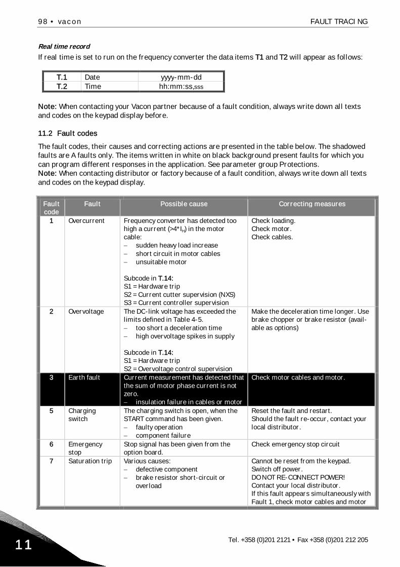
98 • vacon FAULT TRACING
Tel. +358 (0)201 2121 • Fax +358 (0)201 212 20511
Real time record
If real time is set to run on the frequency converter the data items T1 and T2 will appear as follows:
T.1 Date yyyy-mm-ddT.2 Time hh:mm:ss,sss
Note: When contacting your Vacon partner because of a fault condition, always write down all textsand codes on the keypad display before.
11.2 Fault codes
The fault codes, their causes and correcting actions are presented in the table below. The shadowedfaults are A faults only. The items written in white on black background present faults for which youcan program different responses in the application. See parameter group Protections.Note: When contacting distributor or factory because of a fault condition, always write down all textsand codes on the keypad display.
Faultcode
Fault Possible cause Correcting measures
1 Overcurrent Frequency converter has detected toohigh a current (>4*IH) in the motorcable:
sudden heavy load increaseshort circuit in motor cablesunsuitable motor
Subcode in T.14:S1 = Hardware tripS2 = Current cutter supervision (NXS)S3 = Current controller supervision
Check loading.Check motor.Check cables.
2 Overvoltage The DC-link voltage has exceeded thelimits defined in Table 4-5.
too short a deceleration timehigh overvoltage spikes in supply
Subcode in T.14:S1 = Hardware tripS2 = Overvoltage control supervision
Make the deceleration time longer. Usebrake chopper or brake resistor (avail-able as options)
3 Earth fault Current measurement has detected thatthe sum of motor phase current is notzero.
insulation failure in cables or motor
Check motor cables and motor.
5 Chargingswitch
The charging switch is open, when theSTART command has been given.
faulty operationcomponent failure
Reset the fault and restart.Should the fault re-occur, contact yourlocal distributor.
6 Emergencystop
Stop signal has been given from theoption board.
Check emergency stop circuit
7 Saturation trip Various causes:defective componentbrake resistor short-circuit oroverload
Cannot be reset from the keypad.Switch off power.DO NOT RE-CONNECT POWER!Contact your local distributor.If this fault appears simultaneously withFault 1, check motor cables and motor

FAULT TRACING vacon • 99
24-hour support: +358 (0)40 837 1150 • Email: [email protected] 11
8 System fault - component failure- faulty operationNote exceptional fault data recordSubcode in T.14:S1 = Feedback of motor voltageS2 = ReservedS3 = ReservedS4 = ASIC tripS5 = Disturbance in VaconBusS6 = Feedback of charging switchS7 = Charging switchS8 = No power to driver cardS9 = Power unit communication (TX)S10 = Power unit communication (Trip)S11 = Power unit comm. (Measurement)
Reset the fault and restart.Should the fault re-occur, contact yourlocal distributor.
9 Undervoltage DC-link voltage is under the voltagelimits defined in Table 4-5.
most probable cause: too low asupply voltagefrequency converter internal fault
Subcode in T.14:S1 = DC-link too low during runS2 = No data from power unitS3 = Undervoltage control supervision
In case of temporary supply voltagebreak, reset the fault and restart thefrequency converter. Check the supplyvoltage. If it is adequate, an internalfailure has occurred.Contact your local distributor.
10 Input linesupervision
Input line phase is missing.
Subcode in T.14:S1 = Phase supervision diode supplyS2 = Phase supervision active front end
Check supply voltage, fuses and cable.
11 Output phasesupervision
Current measurement has detected thatthere is no current in one motor phase.
Check motor cable and motor.
12 Brake choppersupervision
no brake resistor installedbrake resistor is brokenbrake chopper failure
Check brake resistor and cabling.If ok, the chopper is faulty. Contact yourlocal distributor.
13 Frequency con-verter under-temperature
Heatsink temperature is under –10 C
14 Frequency con-verter over-temperature
Heatsink temperature is over 90 COvertemperature warning is issuedwhen the heatsink temperature exceeds85 C.S1 = MeasurementS2 = Internal thermistor
Check the correct amount and flow ofcooling air.Check the heatsink for dust.Check the ambient temperature.Make sure that the switching frequencyis not too high in relation to ambienttemperature and motor load.
15 Motor stalled Motor stall protection has tripped. Check motor and load.16 Motor over-
temperatureMotor overheating has been detected byfrequency converter motor temperaturemodel. Motor is overloaded.
Decrease the motor load.If no motor overload exists, check thetemperature model parameters.
17 Motorunderload
Motor underload protection has tripped. Check load.
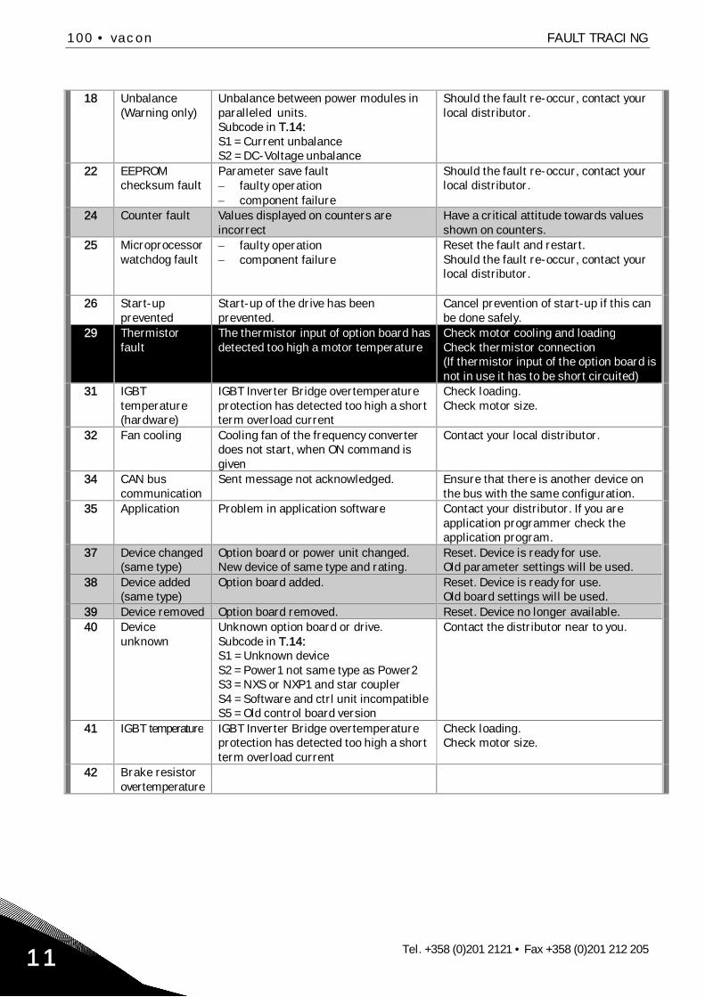
100 • vacon FAULT TRACING
Tel. +358 (0)201 2121 • Fax +358 (0)201 212 20511
18 Unbalance(Warning only)
Unbalance between power modules inparalleled units.Subcode in T.14:S1 = Current unbalanceS2 = DC-Voltage unbalance
Should the fault re-occur, contact yourlocal distributor.
22 EEPROMchecksum fault
Parameter save faultfaulty operationcomponent failure
Should the fault re-occur, contact yourlocal distributor.
24 Counter fault Values displayed on counters areincorrect
Have a critical attitude towards valuesshown on counters.
25 Microprocessorwatchdog fault
faulty operationcomponent failure
Reset the fault and restart.Should the fault re-occur, contact yourlocal distributor.
26 Start-upprevented
Start-up of the drive has beenprevented.
Cancel prevention of start-up if this canbe done safely.
29 Thermistorfault
The thermistor input of option board hasdetected too high a motor temperature
Check motor cooling and loadingCheck thermistor connection(If thermistor input of the option board isnot in use it has to be short circuited)
31 IGBTtemperature(hardware)
IGBT Inverter Bridge overtemperatureprotection has detected too high a shortterm overload current
Check loading.Check motor size.
32 Fan cooling Cooling fan of the frequency converterdoes not start, when ON command isgiven
Contact your local distributor.
34 CAN buscommunication
Sent message not acknowledged. Ensure that there is another device onthe bus with the same configuration.
35 Application Problem in application software Contact your distributor. If you areapplication programmer check theapplication program.
37 Device changed(same type)
Option board or power unit changed.New device of same type and rating.
Reset. Device is ready for use.Old parameter settings will be used.
38 Device added(same type)
Option board added. Reset. Device is ready for use.Old board settings will be used.
39 Device removed Option board removed. Reset. Device no longer available.40 Device
unknownUnknown option board or drive.Subcode in T.14:S1 = Unknown deviceS2 = Power1 not same type as Power2S3 = NXS or NXP1 and star couplerS4 = Software and ctrl unit incompatibleS5 = Old control board version
Contact the distributor near to you.
41 IGBT temperature IGBT Inverter Bridge overtemperatureprotection has detected too high a shortterm overload current
Check loading.Check motor size.
42 Brake resistorovertemperature

FAULT TRACING vacon • 101
24-hour support: +358 (0)40 837 1150 • Email: [email protected] 11
43 Encoder fault Problem detected in encoder signals.Sub code in T.14:S1 =Encoder 1 channel A is missingS2 =Encoder 1 channel B is missingS3 =Both enc. 1 channels are missingS4 =Encoder reversedS5 =Encoder board missingS6 = Serial communication faultS7 = Channel A/Channel B mismatchS8 = Resolver/Motor pole pair mismatchS9 = Missed start angle
Check encoder channel connections.Check the encoder board.
44 Device changed(different type)
Option board or power unit changed.New device of different type or differentrating than the previous one.
ResetSet the option board parameters again ifoption bard changed. Set converterparameters again if power unit changed.
45 Device added(different type)
Option board of different type added. ResetSet the option board parameters again.
49 Div by zero inapplication
A division by zero has occurred in theapplication program.
Contact your distributor. If you areapplication programmer check theapplication program.
50 Analogue inputIin < 4mA (sel.signal range 4to 20 mA)
Current at the analogue input is < 4mA.control cable is broken or loosesignal source has failed
Check the current loop circuitry.
51 External fault Digital input fault.52 Keypad
communicationfault
The connection between the controlkeypad and the frequency converter isbroken.
Check keypad connection and possiblekeypad cable.
53 Fieldbus fault The data connection between thefieldbus Master and the fieldbus boardis broken
Check installation.If installation is correct contact thenearest Vacon distributor.
54 Slot fault Defective option board or slot Check board and slot.Contact the nearest Vacon distributor.
56 PT100 boardtemp. fault
Temperature limit values set for thePT100 board parameters have beenexceeded
Find the cause of temperature rise
Table 11-2. Fault codes

Vacon distributor: