Numerical analysis and control of the recirculation bubble
16
MultiCraft International Journal of Engineering, Science and Technology Vol. 2, No. 4, 2010, pp. 1-16 INTERNATIONAL JOURNAL OF ENGINEERING SCIENCE AND TECHNOLOGY www.ijest-ng.com © 2010 MultiCraft Limited. All rights reserved Numerical analysis and control of the recirculation bubble strength of turbulent confined jet flow using inlet swirl Manas Naskar, Debasish Roy and Snehamoy Majumder * Department of Mechanical Engineering, Jadavpur University, Kolkata-700032, INDIA * Corresponding Author, e-mail: - [email protected] Abstract Numerical investigation of the turbulent jet flows, both central and annular type of jets has been carried out with the introduction of swirl at the inlet using the modified ε κ − model. It was observed that the recirculation bubble generated by the central jet without swirl diminishes in size due to increase in swirl number, while in the case of annular jet the recirculation bubble size grows gradually by the same. Keywords: swirl, turbulent jet, modified ε κ − model, recirculation bubble 1. Introduction The Turbulent confined jet flows are very important for the design of furnaces, mixing devices, cooling of turbine blades and lots of other devices in engineering applications. The Swirl promoted at inlet with the jet flow enhances and controls the mixing operation for the stabilization of the combustion flame (Lefvbre, 1983) by the presence of the central re-circulation bubble. The central region with the presence of re-circulation bubble plays an important role for the flame stabilization in combustion systems. A confined jet comprises higher velocity fluid at the central region with comparatively lower velocity of the same or other fluid embracing the core flow. The opposite is also possible where the core flow is relatively slower than the outer embracing fluid. In case of jet pump, the re-circulation occurs in the flow resulting in loss of flow energy associated with the damage of the solids carried out by that flow field. The solids passing through the mixing region faces a chaotic motion and rotated vigorously, colliding with the region boundary violently. Control of such re-circulation bubble is necessary for the effective transport of the food items etc without any damage. It is therefore very much essential to sort out suitable methodology to control the generation of the recirculation bubble in different devices without ignoring the basic features of jet flows used for special effects in the flow field. The present study aims at doing so by the introduction of swirl promoted at inlet. The comprehensive research on the jet flow started long before. However those works can be broadly classified in two major categories. In the first category the following works have been dedicated mainly to study the confined jet flow in different flow geometry and boundary conditions. Thring and Newby (1952) and Hill (1965) experimentally determined the pressure and mean velocity distributions. Curtet (1962) established an approximate theory for a confined jet, which has been supported by Curtet and Ricou (1964) and Curtet and Barchilon (1964) by their experimental data. Becker et al (1965) experimentally obtained some data of the flow separation in a confined jet flow for a single diameter ratio. They expressed the experimental results by a single parameter, called Craya-Curtet number, which is a flow and geometrical parameter depending on the diameters and velocities. The same number may be defined as the inverse square root of the total momentum, non–dimensionalized by the volume flux and the duct area. Chigier and Chervinsky (1987) conducted experiments on turbulent axisymmetric free jets covering weak, moderate and strong swirl. Razinsky (1969) in his Ph.D. work analyzed the confined jet mixing. Brighton et al (1968) too analyzed the turbulent mixing of confined axi-symetric jets. Exley and Brighton (1971) experimentally investigated flow separation and reattachment in confined jet mixing. Kubo and Gouldin (1975) numerically analyzed turbulent swirling flow. In the majority of these works swirl was not used. Few of them employed swirl for investigating enhanced mixing criteria. In the second category of jet research works, attention has been focused towards the swirl actuated jet flow. Ribeiro and Whitelaw (1980) experimentally analyzed the co-axial jets with and without swirl and measured the Reynolds stresses using Hot
Transcript of Numerical analysis and control of the recirculation bubble
MultiCraft
International Journal of Engineering, Science and Technology
Vol. 2, No. 4, 2010, pp. 1-16
INTERNATIONAL JOURNAL OF
ENGINEERING SCIENCE AND TECHNOLOGY
www.ijest-ng.com
© 2010 MultiCraft Limited. All rights reserved
Numerical analysis and control of the recirculation bubble strength of
turbulent confined jet flow using inlet swirl
Manas Naskar, Debasish Roy and Snehamoy Majumder*
Department of Mechanical Engineering, Jadavpur University, Kolkata-700032, INDIA
* Corresponding Author, e-mail: - [email protected]
Abstract Numerical investigation of the turbulent jet flows, both central and annular type of jets has been carried out with the introduction of swirl at the inlet using the modified εκ − model. It was observed that the recirculation bubble generated by the central jet without swirl diminishes in size due to increase in swirl number, while in the case of annular jet the recirculation bubble size grows gradually by the same. Keywords: swirl, turbulent jet, modified εκ − model, recirculation bubble 1. Introduction The Turbulent confined jet flows are very important for the design of furnaces, mixing devices, cooling of turbine blades and lots of other devices in engineering applications. The Swirl promoted at inlet with the jet flow enhances and controls the mixing operation for the stabilization of the combustion flame (Lefvbre, 1983) by the presence of the central re-circulation bubble. The central region with the presence of re-circulation bubble plays an important role for the flame stabilization in combustion systems. A confined jet comprises higher velocity fluid at the central region with comparatively lower velocity of the same or other fluid embracing the core flow. The opposite is also possible where the core flow is relatively slower than the outer embracing fluid. In case of jet pump, the re-circulation occurs in the flow resulting in loss of flow energy associated with the damage of the solids carried out by that flow field. The solids passing through the mixing region faces a chaotic motion and rotated vigorously, colliding with the region boundary violently. Control of such re-circulation bubble is necessary for the effective transport of the food items etc without any damage. It is therefore very much essential to sort out suitable methodology to control the generation of the recirculation bubble in different devices without ignoring the basic features of jet flows used for special effects in the flow field. The present study aims at doing so by the introduction of swirl promoted at inlet. The comprehensive research on the jet flow started long before. However those works can be broadly classified in two major categories. In the first category the following works have been dedicated mainly to study the confined jet flow in different flow geometry and boundary conditions. Thring and Newby (1952) and Hill (1965) experimentally determined the pressure and mean velocity distributions. Curtet (1962) established an approximate theory for a confined jet, which has been supported by Curtet and Ricou (1964) and Curtet and Barchilon (1964) by their experimental data. Becker et al (1965) experimentally obtained some data of the flow separation in a confined jet flow for a single diameter ratio. They expressed the experimental results by a single parameter, called Craya-Curtet number, which is a flow and geometrical parameter depending on the diameters and velocities. The same number may be defined as the inverse square root of the total momentum, non–dimensionalized by the volume flux and the duct area. Chigier and Chervinsky (1987) conducted experiments on turbulent axisymmetric free jets covering weak, moderate and strong swirl. Razinsky (1969) in his Ph.D. work analyzed the confined jet mixing. Brighton et al (1968) too analyzed the turbulent mixing of confined axi-symetric jets. Exley and Brighton (1971) experimentally investigated flow separation and reattachment in confined jet mixing. Kubo and Gouldin (1975) numerically analyzed turbulent swirling flow. In the majority of these works swirl was not used. Few of them employed swirl for investigating enhanced mixing criteria. In the second category of jet research works, attention has been focused towards the swirl actuated jet flow. Ribeiro and Whitelaw (1980) experimentally analyzed the co-axial jets with and without swirl and measured the Reynolds stresses using Hot
Naskar et al./ International Journal of Engineering, Science and Technology, Vol. 2, No. 4, 2010, pp. 1-16
2
Wire Anemometer. Johnson and Bennett (1981) experimentally studied non-reacting confined co-axial jet and estimated the detailed velocity distribution. Roaback and Johnson (1983) repeated the non-swirling experiments of Johnson and Bennett (1981) promoting swirl and reported identical results with the presence of the central re-circulation zone completing mixing at a length of 33% of that of non-swirling one. So et al (1985) experimentally determined jet characteristics in confined swirling flows using vane-type swirler. Askelvoll and Moin (1996) repeated the work of Johnson and Bennett (1981) by Large Eddy Simulation (LES). Later Pierce and Moin (1988a and 1988b) numerically validated the work of Roaback and Johnson (1983) by LES method. The agreement between the results was excellent. Nejad et al (1989) applied laser velocimetry for characterization of confined swirling flow. Kitoh (1991) cited very important and meaningful results in his work investigating experimentally the turbulent swirling flow in a straight pipe. Zue and Shih (1994) numerically analyzed confined turbulent jets. Tsung et al (1994) numerically predicted the bifurcation of confined swirling flows. Sharif and Wong (1995) numerically evaluated the performance of three turbulence closure models in the prediction of confined swirling flow. Andrew and Christopher (1996) computed turbulent ax-symmetric and non-axisymmetric jet flows using the εκ − model. Wang et al (2004) theoretically and experimentally analyzed swirling jets. Champagne and Kromat (2000) experimentally estimated the range of swirl number and mass flow for inner recirculation zone generation. However in all of the works either the concentration was focused on swirl promoted mixing or it was dedicated purely to investigate the physics behind the flow separation. No works was dedicated to investigate whether recirculation bubble eliminated or further strengthens by the introduction and variations of jet variables or swirl intensity. The present authors are unaware of any control of the recirculation bubbles by the introduction of swirl at inlet. In this present work we have studied how to control the recirculation bubble strength generated by the jet flow, which is very important for the performance of different appliances like the combustion chamber etc. 2. Mathematical Formulation 2.1. Governing Equations: The behavior of the flow is dictated by the conservation of mass, momentum, and passive scalar. Here we consider a steady and
incompressible turbulent flow having single species and constant properties.
Continuity Equation: -
0)(1)(=
∂∂
+∂
∂rvr
rzu ρρ (1)
Momentum Equations: Axial component (z-component):
⎥⎦
⎤⎢⎣
⎡⎟⎠
⎞⎜⎝
⎛∂∂
∂∂
+⎟⎠
⎞⎜⎝
⎛∂∂
∂∂
+⎟⎠
⎞⎜⎝
⎛∂∂
∂∂
+⎟⎠
⎞⎜⎝
⎛∂∂
∂∂
+∂∂
−=⎥⎦
⎤⎢⎣
⎡∂∂
+∂∂
zv
effrrrz
ueffz
ru
effrrrz
ueffzz
pzuu
ruv
μμ
μμρ
1
1
(2)
Radial component (r-component):
rw
r
veffr
veffr
rrru
effz
rv
effrrrz
veffzr
pzvu
rvv
2
221
1
ρμμμ
μμρ
+−⎥⎦
⎤⎢⎣
⎡⎟⎠⎞
⎜⎝⎛
∂∂
∂∂
+⎟⎠⎞
⎜⎝⎛
∂∂
∂∂
+⎟⎠⎞
⎜⎝⎛
∂∂
∂∂
+⎟⎠⎞
⎜⎝⎛
∂∂
∂∂
+∂∂
−=⎥⎦⎤
⎢⎣⎡
∂∂
+∂∂
(3)
Azimuthal Component ( −θ component):
( )φμφ
μφ
μφφ
ρ effrrreffrrrzeffzz
ur
v∂∂
−⎟⎠⎞
⎜⎝⎛
∂∂
∂∂
+⎟⎠⎞
⎜⎝⎛
∂∂
∂∂
=⎥⎦⎤
⎢⎣⎡
∂∂
+∂∂ 21 (4)
Naskar et al./ International Journal of Engineering, Science and Technology, Vol. 2, No. 4, 2010, pp. 1-16
3
Where wandvu , are the mean velocity components along θandrz, directions respectively and the variable wr=φ . Also, ρ and p are constant density and average pressure. The effective viscosity is, tleff μμμ += (5)
Where lμ and tμ stand for molecular or laminar viscosity and eddy or turbulent viscosity respectively. The eddy viscosity is given by:
εμρμ /2kCt = (6)
Where μC is given by Leschziner and Rodi (1981), also details discussed in (Majumder and sanyal, 2008).
⎥⎥
⎦
⎤
⎢⎢
⎣
⎡
⎟⎟⎠
⎞⎜⎜⎝
⎛+
∂∂
+
−=
cRSU
CRSU
nSUkK
KKC
2
22181
21
ε
μ (7)
Here, 22 vusU += , cR = Radius of curvature of the streamline concerned ( =ψ constant). n is the unit normal vector, k and ε are Turbulent kinetic energy and Turbulent dissipation rate respectively while 1K and 2K are two constants and equal to 0.27 and 0.3334 respectively. The value of μC is arbitrarily kept constrained between 0.025 and 0.09 (Leschziner. and Rodi 1981; Majumder and Sanyal 2008). 2.2 Turbulent Modeling: The ε−k equations are given by: −k Equation:
ερσμ
μσμ
μρ −+⎥⎥⎦
⎤
⎢⎢⎣
⎡
∂∂
⎟⎟⎠
⎞⎜⎜⎝
⎛+
∂∂
+⎥⎥⎦
⎤
⎢⎢⎣
⎡
∂∂
⎟⎟⎠
⎞⎜⎜⎝
⎛+
∂∂
=⎥⎦⎤
⎢⎣⎡
∂∂
+∂∂ G
rk
kt
lrrrz
k
kt
lzrkv
zku 1 (8)
Where, G is the production term and given by:
⎥⎥⎥
⎦
⎤
⎢⎢⎢
⎣
⎡⎟⎠
⎞⎜⎝
⎛∂∂
+⎟⎠
⎞⎜⎝
⎛ −∂∂
+⎟⎠
⎞⎜⎝
⎛∂∂
+∂∂
+⎪⎭
⎪⎬⎫
⎪⎩
⎪⎨⎧
⎟⎠
⎞⎜⎝
⎛+⎟⎠
⎞⎜⎝
⎛∂∂
+⎟⎠
⎞⎜⎝
⎛∂∂
=222222
2zw
rw
rw
zv
ru
rv
zu
rv
tG μ
−ε Equation
kC
kGC
rt
lrrrz
tlzr
vz
u2
211 ε
ρεε
εε
εσμ
με
εσμ
μεε
ρ −+⎥⎥⎦
⎤
⎢⎢⎣
⎡
∂∂
⎟⎟⎠
⎞⎜⎜⎝
⎛+
∂∂
+⎥⎥⎦
⎤
⎢⎢⎣
⎡
∂∂
⎟⎟⎠
⎞⎜⎜⎝
⎛+
∂∂
=⎥⎦⎤
⎢⎣⎡
∂∂
+∂∂
(9) Here, kCC σεε ,2,1 and εσ are the empirical turbulence constants, the value of which is given in the table 1 given below Table 1: Model Constants
1εc 2εC kσ εσ
1.44 1.92 1.0 1.3
The wall function (Majumder and Sanyal, 2008) has been adopted for the solution of the modified ε−k equations. 2.3 The Swirl number The level of swirl is represented by the swirl number, defined as the ratio between the axial flux of the swirl momentum to the axial flux of the axial momentum.
Naskar et al./ International Journal of Engineering, Science and Technology, Vol. 2, No. 4, 2010, pp. 1-16
4
∫
∫
=R
rdrUR
RdrrWU
S
0
2
0
2
(10)
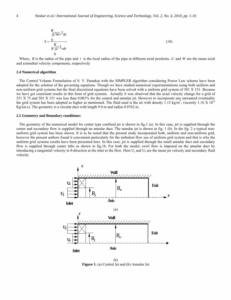
Where, R is the radius of the pipe and r is the local radius of the pipe at different axial positions. U and W are the mean axial and azimuthal velocity components, respectively 2.4 Numerical algorithm The Control Volume Formulation of S. V. Patankar with the SIMPLER algorithm considering Power Law scheme have been adopted for the solution of the governing equations. Though we have studied numerical experimentations using both uniform and non-uniform grid systems but the final discretized equations have been solved with a uniform grid system of 501 X 151. Because we have got consistent results in this form of grid systems. Actually it was observed that the axial velocity change for a grid of 251 X 75 and 501 X 151 was less than 0.001% for the central and annular jet. However to incorporate any unwanted eventuality the grid system has been adopted as higher as mentioned. The fluid used is the air with density 1.15 kg/m3, viscosity 1.16 X 10⁻⁶ Kg/(m.s). The geometry is a circular duct with length 9.0 m and radius 0.0762 m. 2.5 Geometry and Boundary conditions: The geometry of the numerical model for center type confined jet is shown in fig.1 (a). In this case, jet is supplied through the center and secondary flow is supplied through an annular duct. The annular jet is shown in fig. 1 (b). In the fig. 2 a typical non-uniform grid system has been shown. It is to be noted that the present study incorporated both, uniform and non-uniform grid, however the present authors found it convenient particularly for the turbulent flow use of uniform grid system and that is why the uniform grid systems results have been presented here. In this case, jet is supplied through the small annular duct and secondary flow is supplied through center tube as shown in fig.1b. For both the model, swirl flow is imposed on the annular duct by introducing a tangential velocity in θ-direction at the inlet to the flow. Here Uj and Uf are the mean jet velocity and secondary fluid velocity.
Axis
Wall
Exit
r
Uf
Uj z
Inlet
Rj Ro
(a)
Axis
Exit
r
Uj
Uf
Wall
Inlet
Rj Ro
(b)
Figure 1. (a) Central Jet and (b) Annular Jet
Naskar et al./ International Journal of Engineering, Science and Technology, Vol. 2, No. 4, 2010, pp. 1-16
5
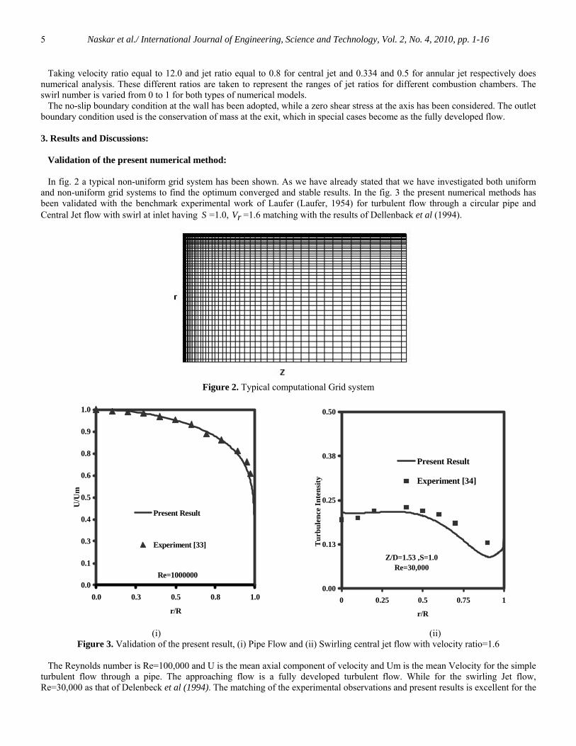
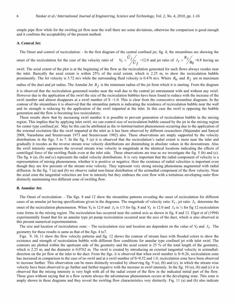
Taking velocity ratio equal to 12.0 and jet ratio equal to 0.8 for central jet and 0.334 and 0.5 for annular jet respectively does numerical analysis. These different ratios are taken to represent the ranges of jet ratios for different combustion chambers. The swirl number is varied from 0 to 1 for both types of numerical models. The no-slip boundary condition at the wall has been adopted, while a zero shear stress at the axis has been considered. The outlet boundary condition used is the conservation of mass at the exit, which in special cases become as the fully developed flow. 3. Results and Discussions: Validation of the present numerical method: In fig. 2 a typical non-uniform grid system has been shown. As we have already stated that we have investigated both uniform and non-uniform grid systems to find the optimum converged and stable results. In the fig. 3 the present numerical methods has been validated with the benchmark experimental work of Laufer (Laufer, 1954) for turbulent flow through a circular pipe and Central Jet flow with swirl at inlet having S =1.0, rV =1.6 matching with the results of Dellenback et al (1994).
Figure 2. Typical computational Grid system
Re=10000000.0
0.1
0.3
0.4
0.5
0.6
0.8
0.9
1.0
0.0 0.3 0.5 0.8 1.0
r/R
U/U
m
Present Result
Experiment [33]
Z/D=1.53 ,S=1.0 Re=30,000
0.00
0.13
0.25
0.38
0.50
0 0.25 0.5 0.75 1
r/R
Tur
bule
nce
Inte
nsity
Present Result
Experiment [34]
(i) (ii)
Figure 3. Validation of the present result, (i) Pipe Flow and (ii) Swirling central jet flow with velocity ratio=1.6 The Reynolds number is Re=100,000 and U is the mean axial component of velocity and Um is the mean Velocity for the simple turbulent flow through a pipe. The approaching flow is a fully developed turbulent flow. While for the swirling Jet flow, Re=30,000 as that of Delenbeck et al (1994). The matching of the experimental observations and present results is excellent for the
Naskar et al./ International Journal of Engineering, Science and Technology, Vol. 2, No. 4, 2010, pp. 1-16
6
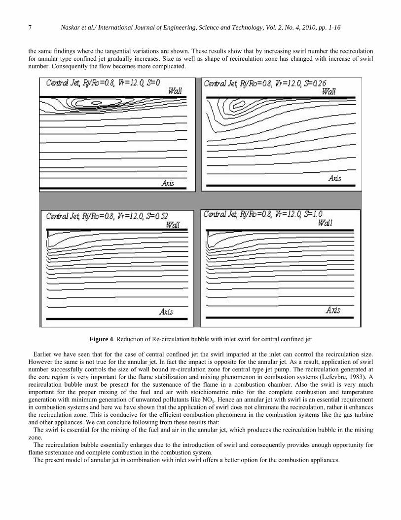
simple pipe flow while for the swirling jet flow near the wall there are some deviations, otherwise the comparison is good enough and it confirms the acceptability of the present method. A. Central Jet: The Onset and control of recirculation: - In the first diagram of the central confined jet, fig. 4, the streamlines are showing the
onset of the recirculation for the case of the velocity ratio of fU
jUrV = =12.0 and jet ratio of
0RjR
rJ = =0.8 having no
swirl. The axial extent of the plot is at the beginning of the flow as the recirculation generated for such flows always resides near the inlet. Basically the axial extent is within 25% of the axial extent, which is 2.25 m, to show the recirculation bubble prominently. The Jet velocity is 5.72 m/s while the surrounding fluid velocity is 0.476 m/s. Where oR and jR are m maximum
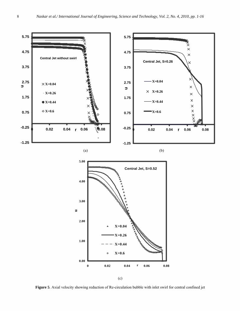
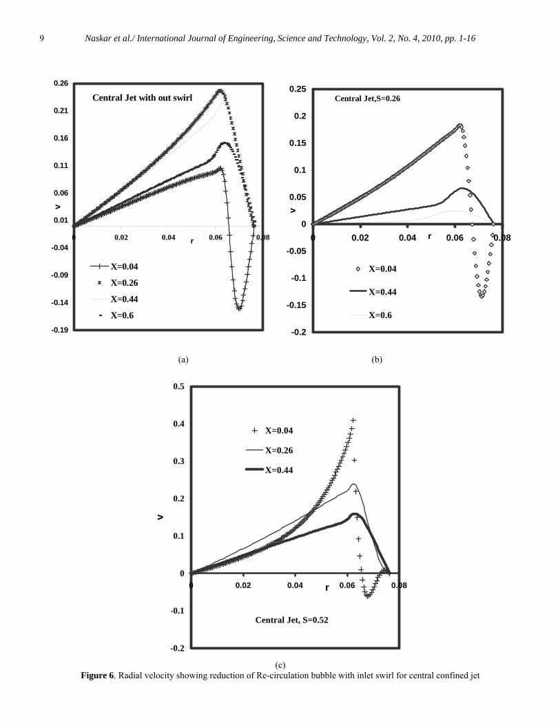
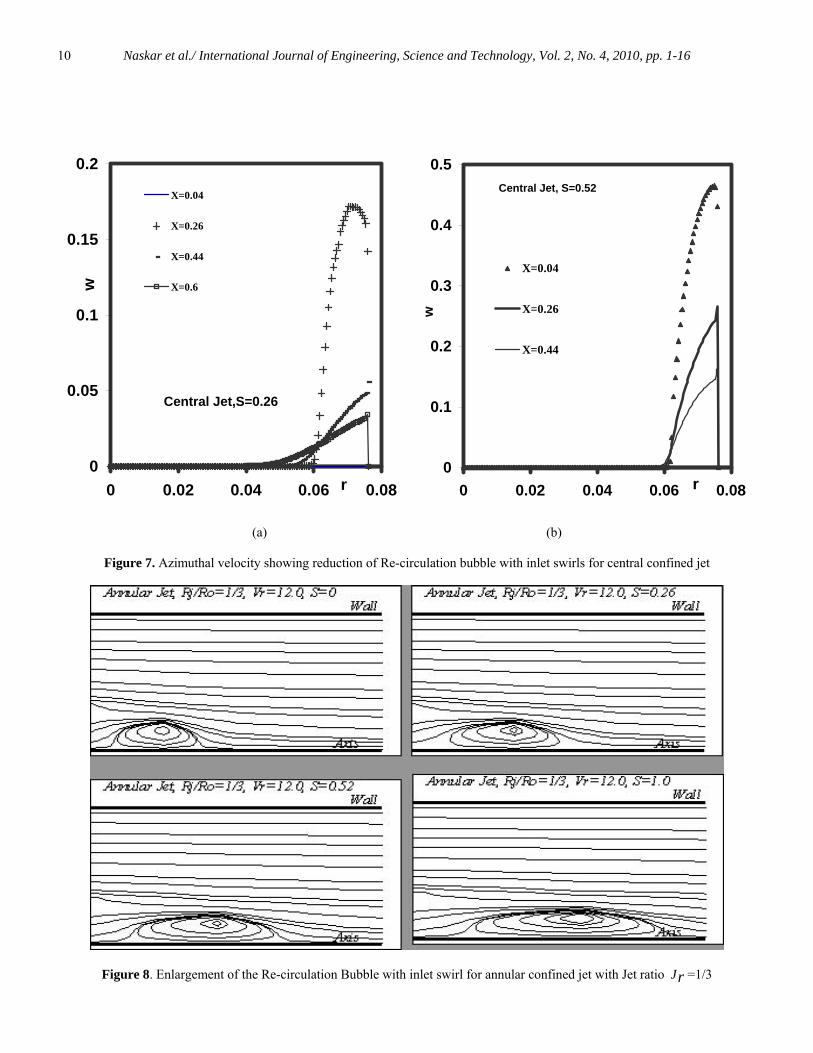
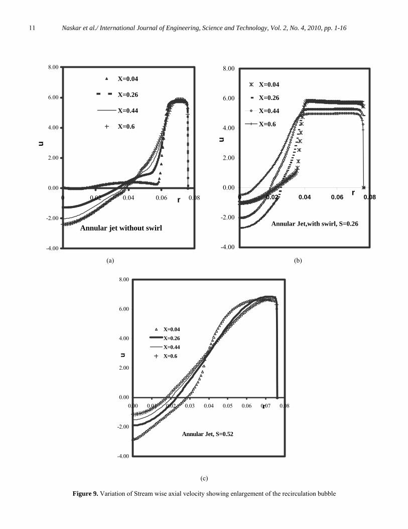
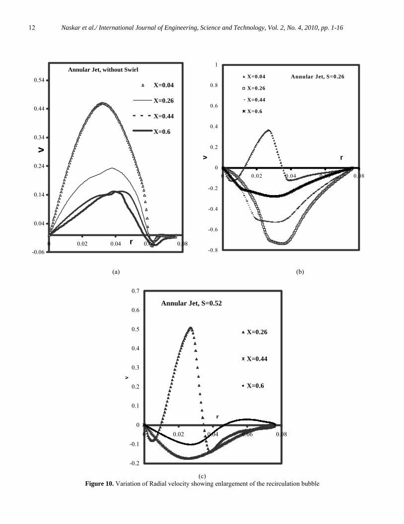
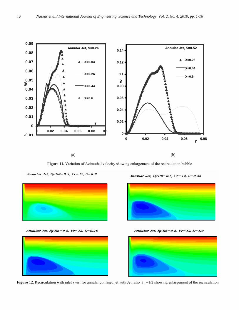
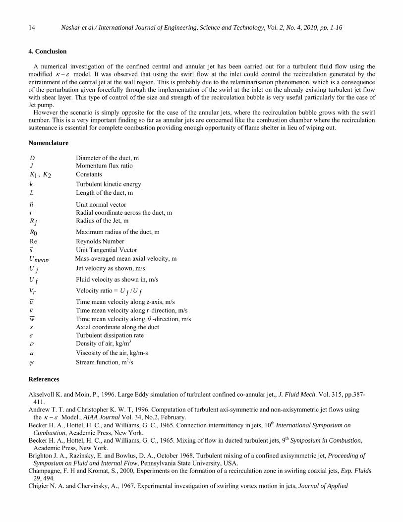
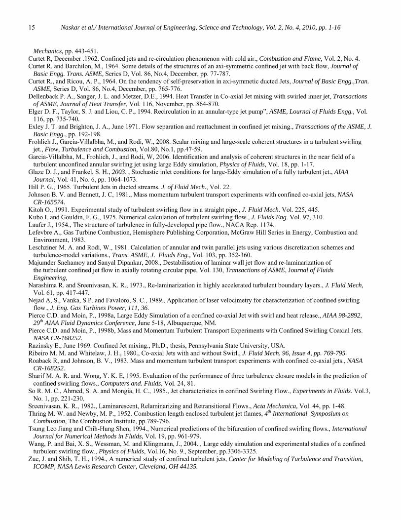
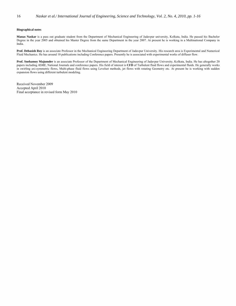
radius of the duct and jet radius. The Annular Jet jR is the minimum radius of the jet from which it is starting. From the diagram it is observed that the recirculation generated resides near the wall due to the central jet entrainment with and without any swirl. However due to the application of the swirl the size of the recirculation bubbles have been found to reduce with the increase of the swirl number and almost disappears at a swirl number of S =1.0. This is clear from the consecutive streamline diagrams. In the contour of the streamlines it is observed that the streamline pattern is indicating the residence of recirculation bubble near the wall and its strength is reducing by the application of the swirl imparted at the inlet. In this case the swirl is opposing the bubble generation and the flow is becoming less recirculatory. These results show that by increasing swirl number it is possible to prevent generation of recirculation bubble in the mixing region. This implies that by applying inlet swirl, we can control size of recirculation bubble caused by the jet in the mixing region for center type confined jet. May be this can be attributed as the re-laminarisation phenomenon occurring due to the application of the external excitation like the swirl imparted at the inlet as it has been observed by different researchers (Majumder and Sanyal 2008, Narashima and Sreenivasan 1973 and Sreenivasan 1982) also. These observations are amply supported by the velocity distributions in the figs. 5 to 7. In the fig. 5 (a) it is observed that the recirculation’s radial extent is more near the inlet and gradually it recedes as the reverse stream wise velocity distributions are diminishing in absolute values in the downstream. Also the swirl intensity suppresses the reversal stream wise velocity in magnitude at the identical locations indicating the effects of centrifugal force of the swirling fluids even at the inlet side. These observations are true as we investigate the fig. 5 (b) and (c). The fig. 6 (a), (b) and (c) represents the radial velocity distributions. It is very important that the radial component of velocity is a representation of mixing phenomenon, whether it is positive or negative. Here the existence of radial velocities is important even though they are few percents of the stream wise velocity. They represent very strong mixing phenomena augmented with radial diffusion. In the fig. 7 (a) and (b) we observe radial non-linear distribution of the azimuthal component of the flow velocity. Near the axial zone the tangential velocities are low in intensity but they embrace the core flow with a tortuitous enveloping outer flow distinctly maintaining two different zone of swirling flow. B. Annular Jet: The Onset of recirculation: - The figs. 8 and 12 show the streamline patterns revealing the onset of recirculation for different cases of an annular jet having specifications given in the diagrams. The magnitude of velocity ratio rV , jet ratio rJ determine the onset of the recirculation phenomenon. When rV is 12.0 and rJ is 1/3 for fig. 8 and rV is 12.0 and rJ is ½ for fig 12 recirculation zone forms in the mixing region. The recirculation has occurred near the central axis as shown in fig. 8 and 12. Elger et al (1994) experimentally found that for an annular type jet pump recirculation occurred near the axis of the duct, which is also observed in this present numerical experimentation. The size and location of recirculation zone: - The recirculation size and location are dependent on the value of rV and rJ . The geometry for these results is same as that of the figs. 4 to7. Figs. 9, 10, 11 show the flow velocity patterns and fig. 12 shows the contour of stream lines with flooded colors to show the existence and strength of recirculation bubble with different flow conditions for annular type confined jet with inlet swirl. The contours are plotted within the upstream side of the geometry and the axial extent is 25 % of the total length of the geometry, which is 2.25 m, and the diameter is 0.0762 m. The swirl is created by introducing an external tangential velocity in azimuthal-direction on the jet flow at the inlet to the duct. From the figs. it is observed that when swirl number is S=0.26, recirculation zone has increased in comparison to the case of no swirl and at a swirl number of S=0.52 and 1.0, recirculation zone have been observed to increase further. This observation can be more distinctly revealed by observing fig. 9 (a), (b) and (c), in which the stream wise velocity have been observed to go further and further negative with the increase in swirl intensity. In the fig. 10 (a), (b) and (c) it is observed that the mixing intensity is very high with all of the radial extent of the flow in the indicated initial part of the flow. These goes without saying that in a flow system always the adventurous phenomenon occurs at the developing zone. This zone is amply shown in these diagrams and they reveal the swirling flow characteristics very distinctly. Fig. 11 (a) and (b) also indicate
Naskar et al./ International Journal of Engineering, Science and Technology, Vol. 2, No. 4, 2010, pp. 1-16
7
the same findings where the tangential variations are shown. These results show that by increasing swirl number the recirculation for annular type confined jet gradually increases. Size as well as shape of recirculation zone has changed with increase of swirl number. Consequently the flow becomes more complicated.
Figure 4. Reduction of Re-circulation bubble with inlet swirl for central confined jet Earlier we have seen that for the case of central confined jet the swirl imparted at the inlet can control the recirculation size. However the same is not true for the annular jet. In fact the impact is opposite for the annular jet. As a result, application of swirl number successfully controls the size of wall bound re-circulation zone for central type jet pump. The recirculation generated at the core region is very important for the flame stabilization and mixing phenomenon in combustion systems (Lefevbre, 1983). A recirculation bubble must be present for the sustenance of the flame in a combustion chamber. Also the swirl is very much important for the proper mixing of the fuel and air with stoichiometric ratio for the complete combustion and temperature generation with minimum generation of unwanted pollutants like NOx. Hence an annular jet with swirl is an essential requirement in combustion systems and here we have shown that the application of swirl does not eliminate the recirculation, rather it enhances the recirculation zone. This is conducive for the efficient combustion phenomena in the combustion systems like the gas turbine and other appliances. We can conclude following from these results that: The swirl is essential for the mixing of the fuel and air in the annular jet, which produces the recirculation bubble in the mixing zone. The recirculation bubble essentially enlarges due to the introduction of swirl and consequently provides enough opportunity for flame sustenance and complete combustion in the combustion system. The present model of annular jet in combination with inlet swirl offers a better option for the combustion appliances.
Naskar et al./ International Journal of Engineering, Science and Technology, Vol. 2, No. 4, 2010, pp. 1-16
8
Central Jet without swirl
-1.25
-0.25
0.75
1.75
2.75
3.75
4.75
5.75
0 0.02 0.04 0.06 0.08r
u X=0.04
X=0.26
X=0.44
X=0.6
Central Jet, S=0.26
-1.25
-0.25
0.75
1.75
2.75
3.75
4.75
5.75
0 0.02 0.04 0.06 0.08ru
X=0.04
X=0.26
X=0.44
X=0.6
(a) (b)
Central Jet, S=0.52
0.00
1.00
2.00
3.00
4.00
5.00
0 0.02 0.04 0.06 0.08r
u
X=0.04
X=0.26
X=0.44
X=0.6
(c)
Figure 5. Axial velocity showing reduction of Re-circulation bubble with inlet swirl for central confined jet
Naskar et al./ International Journal of Engineering, Science and Technology, Vol. 2, No. 4, 2010, pp. 1-16
9
Central Jet with out swirl
-0.19
-0.14
-0.09
-0.04
0.01
0.06
0.11
0.16
0.21
0.26
0 0.02 0.04 0.06 0.08r
v
X=0.04
X=0.26
X=0.44
X=0.6
Central Jet,S=0.26
-0.2
-0.15
-0.1
-0.05
0
0.05
0.1
0.15
0.2
0.25
0 0.02 0.04 0.06 0.08r
v
X=0.04
X=0.44
X=0.6
(a) (b)
Central Jet, S=0.52
-0.2
-0.1
0
0.1
0.2
0.3
0.4
0.5
0 0.02 0.04 0.06 0.08r
v
X=0.04
X=0.26
X=0.44
(c)
Figure 6. Radial velocity showing reduction of Re-circulation bubble with inlet swirl for central confined jet
Naskar et al./ International Journal of Engineering, Science and Technology, Vol. 2, No. 4, 2010, pp. 1-16
10
Central Jet,S=0.26
0
0.05
0.1
0.15
0.2
0 0.02 0.04 0.06 0.08r
w
X=0.04
X=0.26
X=0.44
X=0.6
Central Jet, S=0.52
0
0.1
0.2
0.3
0.4
0.5
0 0.02 0.04 0.06 0.08r
w
X=0.04
X=0.26
X=0.44
(a) (b)
Figure 7. Azimuthal velocity showing reduction of Re-circulation bubble with inlet swirls for central confined jet
Figure 8. Enlargement of the Re-circulation Bubble with inlet swirl for annular confined jet with Jet ratio rJ =1/3
Naskar et al./ International Journal of Engineering, Science and Technology, Vol. 2, No. 4, 2010, pp. 1-16
11
Annular jet without swirl
-4.00
-2.00
0.00
2.00
4.00
6.00
8.00
0 0.02 0.04 0.06 0.08r
u
X=0.04
X=0.26
X=0.44
X=0.6
Annular Jet,with swirl, S=0.26
-4.00
-2.00
0.00
2.00
4.00
6.00
8.00
0 0.02 0.04 0.06 0.08r
u
X=0.04
X=0.26
X=0.44
X=0.6
(a) (b)
Annular Jet, S=0.52
-4.00
-2.00
0.00
2.00
4.00
6.00
8.00
0.00 0.01 0.02 0.03 0.04 0.05 0.06 0.07 0.08r
u
X=0.04X=0.26X=0.44X=0.6
(c)
Figure 9. Variation of Stream wise axial velocity showing enlargement of the recirculation bubble
Naskar et al./ International Journal of Engineering, Science and Technology, Vol. 2, No. 4, 2010, pp. 1-16
12
Annular Jet, without Swirl
-0.06
0.04
0.14
0.24
0.34
0.44
0.54
0 0.02 0.04 0.06 0.08r
v
X=0.04
X=0.26
X=0.44
X=0.6
Annular Jet, S=0.26
-0.8
-0.6
-0.4
-0.2
0
0.2
0.4
0.6
0.8
1
0 0.02 0.04 0.06 0.08
rv
X=0.04
X=0.26
X=0.44
X=0.6
(a) (b)
Annular Jet, S=0.52
-0.2
-0.1
0
0.1
0.2
0.3
0.4
0.5
0.6
0.7
0 0.02 0.04 0.06 0.08
r
v
X=0.26
X=0.44
X=0.6
(c)
Figure 10. Variation of Radial velocity showing enlargement of the recirculation bubble
Naskar et al./ International Journal of Engineering, Science and Technology, Vol. 2, No. 4, 2010, pp. 1-16
13
Annular Jet, S=0.26
-0.01
0
0.01
0.02
0.03
0.04
0.05
0.06
0.07
0.08
0.09
0 0.02 0.04 0.06 0.08 0.1
r
w
X=0.04
X=0.26
X=0.44
X=0.6
Annular Jet, S=0.52
0
0.02
0.04
0.06
0.08
0.1
0.12
0.14
0 0.02 0.04 0.06 0.08r
w
X=0.26
X=0.44
X=0.6
(a) (b)
Figure 11. Variation of Azimuthal velocity showing enlargement of the recirculation bubble
Figure 12. Recirculation with inlet swirl for annular confined jet with Jet ratio rJ =1/2 showing enlargement of the recirculation
Naskar et al./ International Journal of Engineering, Science and Technology, Vol. 2, No. 4, 2010, pp. 1-16
14
4. Conclusion A numerical investigation of the confined central and annular jet has been carried out for a turbulent fluid flow using the modified εκ − model. It was observed that using the swirl flow at the inlet could control the recirculation generated by the entrainment of the central jet at the wall region. This is probably due to the relaminarisation phenomenon, which is a consequence of the perturbation given forcefully through the implementation of the swirl at the inlet on the already existing turbulent jet flow with shear layer. This type of control of the size and strength of the recirculation bubble is very useful particularly for the case of Jet pump. However the scenario is simply opposite for the case of the annular jets, where the recirculation bubble grows with the swirl number. This is a very important finding so far as annular jets are concerned like the combustion chamber where the recirculation sustenance is essential for complete combustion providing enough opportunity of flame shelter in lieu of wiping out. Nomenclature D Diameter of the duct, m J Momentum flux ratio
1K , 2K Constants k Turbulent kinetic energy L Length of the duct, m
nr
Unit normal vector r Radial coordinate across the duct, m
jR Radius of the Jet, m
0R Maximum radius of the duct, m Re Reynolds Number sr
Unit Tangential Vector meanU Mass-averaged mean axial velocity, m
jU Jet velocity as shown, m/s
fU Fluid velocity as shown in, m/s
rV Velocity ratio = fUjU /
u Time mean velocity along z-axis, m/s v Time mean velocity along r-direction, m/s w Time mean velocity along θ -direction, m/s x Axial coordinate along the duct ε Turbulent dissipation rate ρ Density of air, kg/m3
μ Viscosity of the air, kg/m-s ψ Stream function, m2/s References Akselvoll K. and Moin, P., 1996. Large Eddy simulation of turbulent confined co-annular jet., J. Fluid Mech. Vol. 315, pp.387- 411. Andrew T. T. and Christopher K. W. T, 1996. Computation of turbulent axi-symmetric and non-axisymmetric jet flows using the εκ − Model., AIAA Journal Vol. 34, No.2, February. Becker H. A., Hottel, H. C., and Williams, G. C., 1965. Connection intermittency in jets, 10th International Symposium on Combustion, Academic Press, New York. Becker H. A., Hottel, H. C., and Williams, G. C., 1965. Mixing of flow in ducted turbulent jets, 9th Symposium in Combustion, Academic Press, New York. Brighton J. A., Razinsky, E. and Bowlus, D. A., October 1968. Turbulent mixing of a confined axisymmetric jet, Proceeding of Symposium on Fluid and Internal Flow, Pennsylvania State University, USA. Champagne, F. H and Kromat, S., 2000, Experiments on the formation of a recirculation zone in swirling coaxial jets, Exp. Fluids 29, 494. Chigier N. A. and Chervinsky, A., 1967. Experimental investigation of swirling vortex motion in jets, Journal of Applied
Naskar et al./ International Journal of Engineering, Science and Technology, Vol. 2, No. 4, 2010, pp. 1-16
15
Mechanics, pp. 443-451. Curtet R, December .1962. Confined jets and re-circulation phenomenon with cold air., Combustion and Flame, Vol. 2, No. 4. Curtet R. and Barchilon, M., 1964. Some details of the structures of an axi-symmetric confined jet with back flow, Journal of Basic Engg. Trans. ASME, Series D, Vol. 86, No.4, December, pp. 77-787. Curtet R., and Ricou, A. P., 1964. On the tendency of self-preservation in axi-symmetic ducted Jets, Journal of Basic Engg.,Tran. ASME, Series D, Vol. 86, No.4, December, pp. 765-776. Dellenback P. A., Sanger, J. L. and Metzer, D.E., 1994. Heat Transfer in Co-axial Jet mixing with swirled inner jet, Transactions of ASME, Journal of Heat Transfer, Vol. 116, November, pp. 864-870. Elger D. F., Taylor, S. J. and Liou, C. P., 1994. Recirculation in an annular-type jet pump”, ASME, Lournal of Fluids Engg., Vol. 116, pp. 735-740. Exley J. T. and Brighton, J. A., June 1971. Flow separation and reattachment in confined jet mixing., Transactions of the ASME, J. Basic Engg., pp. 192-198. Frohlich J., Garcia-Villalbha, M., and Rodi, W., 2008. Scalar mixing and large-scale coherent structures in a turbulent swirling jet., Flow, Turbulence and Combustion, Vol.80, No.1, pp.47-59. Garcia-Villalbha, M., Frohlich, J., and Rodi, W, 2006. Identification and analysis of coherent structures in the near field of a turbulent unconfined annular swirling jet using large Eddy simulation, Physics of Fluids, Vol. 18, pp. 1-17. Glaze D. J., and Frankel, S. H., 2003. , Stochastic inlet conditions for large-Eddy simulation of a fully turbulent jet., AIAA Journal, Vol. 41, No. 6, pp. 1064-1073. Hill P. G., 1965. Turbulent Jets in ducted streams. J. of Fluid Mech., Vol. 22. Johnson B. V. and Bennett, J. C, 1981., Mass momentum turbulent transport experiments with confined co-axial jets, NASA CR-165574. Kitoh O., 1991. Experimental study of turbulent swirling flow in a straight pipe., J. Fluid Mech. Vol. 225, 445. Kubo I. and Gouldin, F. G., 1975. Numerical calculation of turbulent swirling flow., J. Fluids Eng. Vol. 97, 310. Laufer J., 1954., The structure of turbulence in fully-developed pipe flow., NACA Rep. 1174. Lefevbre A., Gas Turbine Combustion, Hemisphere Publishing Corporation, McGraw Hill Series in Energy, Combustion and Environment, 1983. Leschziner M. A. and Rodi, W., 1981. Calculation of annular and twin parallel jets using various discretization schemes and turbulence-model variations., Trans. ASME, J. Fluids Eng., Vol. 103, pp. 352-360. Majumder Snehamoy and Sanyal Dipankar, 2008., Destabilisation of laminar wall jet flow and re-laminarization of the turbulent confined jet flow in axially rotating circular pipe, Vol. 130, Transactions of ASME, Journal of Fluids Engineering, Narashima R. and Sreenivasan, K. R., 1973., Re-laminarization in highly accelerated turbulent boundary layers., J. Fluid Mech, Vol. 61, pp. 417-447. Nejad A, S., Vanka, S.P. and Favaloro, S. C., 1989., Application of laser velocimetry for characterization of confined swirling flow., J. Eng. Gas Turbines Power, 111, 36. Pierce C.D. and Moin, P., 1998a, Large Eddy Simulation of a confined co-axial Jet with swirl and heat release., AIAA 98-2892, 29th AIAA Fluid Dynamics Conference, June 5-18, Albuquerque, NM. Pierce C.D. and Moin, P., 1998b, Mass and Momentum Turbulent Transport Experiments with Confined Swirling Coaxial Jets. NASA CR-168252. Razinsky E., June 1969. Confined Jet mixing., Ph.D., thesis, Pennsylvania State University, USA. Ribeiro M. M. and Whitelaw, J. H., 1980., Co-axial Jets with and without Swirl., J. Fluid Mech. 96, Issue 4, pp. 769-795. Roaback R, and Johnson, B. V., 1983. Mass and momentum turbulent transport experiments with confined co-axial jets., NASA CR-168252. Sharif M. A. R. and. Wong, Y. K. E, 1995. Evaluation of the performance of three turbulence closure models in the prediction of confined swirling flows., Computers and. Fluids, Vol. 24, 81. So R. M. C., Ahmed, S. A. and Mongia, H. C., 1985., Jet characteristics in confined Swirling Flow., Experiments in Fluids. Vol.3, No. 1, pp. 221-230. Sreenivasan, K. R., 1982., Laminarescent, Relaminarizing and Retransitional Flows., Acta Mechanica, Vol. 44, pp. 1-48. Thring M. W. and Newby, M. P., 1952. Combustion length enclosed turbulent jet flames, 4th International Symposium on Combustion, The Combustion Institute, pp.789-796. Tsung Leo Jiang and Chih-Hung Shen, 1994., Numerical predictions of the bifurcation of confined swirling flows., International Journal for Numerical Methods in Fluids, Vol. 19, pp. 961-979. Wang, P. and Bai, X. S., Wessman, M. and Klingmann, J., 2004. , Large eddy simulation and experimental studies of a confined turbulent swirling flow., Physics of Fluids, Vol.16, No. 9., September, pp.3306-3325. Zue, J. and Shih, T. H., 1994., A numerical study of confined turbulent jets, Center for Modeling of Turbulence and Transition, ICOMP, NASA Lewis Research Center, Cleveland, OH 44135.
Naskar et al./ International Journal of Engineering, Science and Technology, Vol. 2, No. 4, 2010, pp. 1-16
16
Biographical notes Manas Naskar is a pass out graduate student from the Department of Mechanical Engineering of Jadavpur university, Kolkata, India. He passed his Bachelor Degree in the year 2005 and obtained his Master Degree from the same Department in the year 2007. At present he is working in a Multinational Company in India. Prof. Debasish Roy is an associate Professor in the Mechanical Engineering Department of Jadavpur University. His research area is Experimental and Numerical Fluid Mechanics. He has around 10 publications including Conference papers. Presently he is associated with experimental works of diffuser flow. Prof. Snehamoy Majumder is an associate Professor of the Department of Mechanical Engineering of Jadavpur University, Kolkata, India. He has altogether 20 papers including ASME, National Journals and conference papers. His field of interest is CFD of Turbulent fluid flows and experimental fluids. He generally works in swirling axi-symmetric flows, Multi-phase fluid flows using Levelset methods, jet flows with rotating Geometry etc. At present he is working with sudden expansion flows using different turbulent modeling. Received November 2009 Accepted April 2010 Final acceptance in revised form May 2010