Nucleate Boiling and Critical Heat Flux From Protruded ... Publications/36.pdfMiniaturization of...
11
CO. Gersey Graduate Student. I. Mudawar Associate Professor and Director. Boiling and Two-Phase Flow Laboratory, School of Mechanical Engineering, Purdue University, West Lafayette, IN 47907 Nucleate Boiling and Critical Heat Flux From Protruded Chip Arrays During Flow Boiling The effects of chip protrusion on the forced-convection boiling and critical heat flux (CHF) of a dielectric coolant (FC-72) were investigated. The multi-chip module used in the present study featured a linear array of nine, 10mm x 10 mm, simulated microelectronic chips which protruded 1 mm into a 20-mm wide side of a rectangular flow channel. Experiments were performed in vertical upflow with 5-mm and 2-mm channel gap thicknesses. For each configuration, the velocity and subcooling of the liquid were varied from 13 to 400 cm/s and 3 to 36° C, respectively. The nucleate boiling regime was not affected by changes in velocity and subcooling, and critical heat flux generally increased with increases in either velocity or subcooling. Higher single-phase heat transfer coefficients and higher CHF values were measured for the protruded chips compared to similar flush-mounted chips. However, adjusting the data for the increased surface area and the increased liquid velocity above the chip caused by the protruding chips yielded a closer agreement between the protruded and flush-mounted results. Even with the velocity and area adjustments, the most upstream protruded chip had higher single-phase heat transfer coefficients and CHF values for high velocity and/or highly-subcooled flow as compared the downstream protruded chips. The results show that, except for the most upstream chip, the performances of protruded chips are very similar to those of flush-mounted chips. Introduction Miniaturization of electronic components and dense pack- aging of circuit boards have caused electronic packaging en- gineers to look for new cooling technologies which will be able to dissipate as much as 100 W/cm 2 at the chip level (Simons, 1987) while maintaining the device at an acceptable temper- ature. Direct immersion cooling with a dielectric fluid has become a forerunner in this emerging technology because of the high heat transfer coefficients made possible by the intimate contact between the device and the coolant. Because cooling with phase change offers great increases in the heat transfer coefficient, several researchers have examined flow boiling of a dielectric fluid on discrete heat sources which simulate electronic chips. Originally, most of these studies featured a single simulated chip flush-mounted on a channel wall (Lee and Simon, 1989; Maddox and Mudawar, 1989; Mudawar and Maddox, 1989; Samant and Simon, 1989), while more recent studies have examined flow boiling on flush- mounted, multi-chip arrays (Willingham et al., 1991; Gersey and Mudawar, 1992; Willingham and Mudawar, 1992a,b). Only a few studies have addressed the effects of chip protrusion on direct immersion cooling of multi-chip arrays (Garimella and Eibeck, 1990; McGillis et al., 1991). Contributed by the Electrical and Electronic Packaging Division for publi- cation in the JOURNAL OF ELECTRONIC PACKAGING. Manuscript received by the EEPD May 25, 1992; revised manuscript received November 17,1992. Associate Technical Editor: B. G. Sammakia. Single-Phase Cooling. Although little has been published on the direct immersion cooling of protruded chips, forced- convection cooling of protruded chips with air has been ex- tensively studied both numerically and experimentally during the last two decades. A review article by Moffat and Ortega (1988) included a comprehensive summary of the direct air cooling studies, thus only a brief review of some of the pertinent air cooling studies will be presented in the present paper. Unfortunately, many of the numerical studies relevant to forced-convection cooling in a channel examined two-dimen- sional protrusions, such as ribs (Davalath and Bayazitoglu, 1987; Knight and Crawford, 1988). Asako and Faghri (1991) numerically solved for turbulent flow around a three-dimen- sional block simulating an nxm array of heat sources, but the geometrical parameters investigated were not in the range of the current experiment. Empirically, several researchers have discovered that, after • several stream-wise chip rows, the average single-phase heat transfer coefficient for each chip becomes constant: Sparrow et al. (1982) with naphthalene sublimation in air, Faghri et al. (1989) with forced-convection of air, and Garimella and Eibeck (1990) with water. McEntire and Webb (1990) compared the forced-convection heat transfer coefficient for flush-mounted and protruded two-dimensional heat sources in air flow. They observed an increase in the local Nusselt number on the up- stream portion of the heat sources and attributed the increase to the disruption of the thermal boundary layer between heat 78/Vol. 115, MARCH 1993 Transactions of the ASME Copyright © 1993 by ASME Downloaded 27 Jul 2010 to 128.211.178.86. Redistribution subject to ASME license or copyright; see http://www.asme.org/terms/Terms_Use.cfm
Transcript of Nucleate Boiling and Critical Heat Flux From Protruded ... Publications/36.pdfMiniaturization of...
C O . Gersey Graduate Student.
I. Mudawar Associate Professor and Director.
Boiling and Two-Phase Flow Laboratory, School of Mechanical Engineering,
Purdue University, West Lafayette, IN 47907
Nucleate Boiling and Critical Heat Flux From Protruded Chip Arrays During Flow Boiling The effects of chip protrusion on the forced-convection boiling and critical heat flux (CHF) of a dielectric coolant (FC-72) were investigated. The multi-chip module used in the present study featured a linear array of nine, 10mm x 10 mm, simulated microelectronic chips which protruded 1 mm into a 20-mm wide side of a rectangular flow channel. Experiments were performed in vertical upflow with 5-mm and 2-mm channel gap thicknesses. For each configuration, the velocity and subcooling of the liquid were varied from 13 to 400 cm/s and 3 to 36° C, respectively. The nucleate boiling regime was not affected by changes in velocity and subcooling, and critical heat flux generally increased with increases in either velocity or subcooling. Higher single-phase heat transfer coefficients and higher CHF values were measured for the protruded chips compared to similar flush-mounted chips. However, adjusting the data for the increased surface area and the increased liquid velocity above the chip caused by the protruding chips yielded a closer agreement between the protruded and flush-mounted results. Even with the velocity and area adjustments, the most upstream protruded chip had higher single-phase heat transfer coefficients and CHF values for high velocity and/or highly-subcooled flow as compared the downstream protruded chips. The results show that, except for the most upstream chip, the performances of protruded chips are very similar to those of flush-mounted chips.
Introduction Miniaturization of electronic components and dense pack
aging of circuit boards have caused electronic packaging engineers to look for new cooling technologies which will be able to dissipate as much as 100 W/cm2 at the chip level (Simons, 1987) while maintaining the device at an acceptable temperature. Direct immersion cooling with a dielectric fluid has become a forerunner in this emerging technology because of the high heat transfer coefficients made possible by the intimate contact between the device and the coolant.
Because cooling with phase change offers great increases in the heat transfer coefficient, several researchers have examined flow boiling of a dielectric fluid on discrete heat sources which simulate electronic chips. Originally, most of these studies featured a single simulated chip flush-mounted on a channel wall (Lee and Simon, 1989; Maddox and Mudawar, 1989; Mudawar and Maddox, 1989; Samant and Simon, 1989), while more recent studies have examined flow boiling on flush-mounted, multi-chip arrays (Willingham et al., 1991; Gersey and Mudawar, 1992; Willingham and Mudawar, 1992a,b). Only a few studies have addressed the effects of chip protrusion on direct immersion cooling of multi-chip arrays (Garimella and Eibeck, 1990; McGillis et al., 1991).
Contributed by the Electrical and Electronic Packaging Division for publication in the JOURNAL OF ELECTRONIC PACKAGING. Manuscript received by the EEPD May 25, 1992; revised manuscript received November 17,1992. Associate Technical Editor: B. G. Sammakia.
Single-Phase Cooling. Although little has been published on the direct immersion cooling of protruded chips, forced-convection cooling of protruded chips with air has been extensively studied both numerically and experimentally during the last two decades. A review article by Moffat and Ortega (1988) included a comprehensive summary of the direct air cooling studies, thus only a brief review of some of the pertinent air cooling studies will be presented in the present paper.
Unfortunately, many of the numerical studies relevant to forced-convection cooling in a channel examined two-dimensional protrusions, such as ribs (Davalath and Bayazitoglu, 1987; Knight and Crawford, 1988). Asako and Faghri (1991) numerically solved for turbulent flow around a three-dimensional block simulating an nxm array of heat sources, but the geometrical parameters investigated were not in the range of the current experiment.
Empirically, several researchers have discovered that, after • several stream-wise chip rows, the average single-phase heat transfer coefficient for each chip becomes constant: Sparrow et al. (1982) with naphthalene sublimation in air, Faghri et al. (1989) with forced-convection of air, and Garimella and Eibeck (1990) with water. McEntire and Webb (1990) compared the forced-convection heat transfer coefficient for flush-mounted and protruded two-dimensional heat sources in air flow. They observed an increase in the local Nusselt number on the upstream portion of the heat sources and attributed the increase to the disruption of the thermal boundary layer between heat
78/Vol. 115, MARCH 1993 Transactions of the ASME
Copyright © 1993 by ASMEDownloaded 27 Jul 2010 to 128.211.178.86. Redistribution subject to ASME license or copyright; see http://www.asme.org/terms/Terms_Use.cfm

sources. An increase in the average Nusselt number was found to occur on the downstream heat sources for the protruded cases. This was attributed to flow separation, vena contracta, and the transition to turbulent flow caused by the heat source protrusion. Only four ribs were employed in the experiments, thus precluding the ability to confirm the aforementioned observations of constant average heat transfer coefficients after several rows of heat sources.
Roeller et al. (1990) used a laser-Doppler velocimeter (LDV) to measure the flow around a single protruded element in air flow. By varying the chip width and channel height, they noted two competing effects on the resulting heat transfer from the chip. In low Reynolds number flows with large channel heights, three-dimensional flow effects had a dominant effect on the
ficient compared to the other five rows. Using a LDV system, Garimella and Eibeck (1991) measured a sharp increase in the turbulence intensity directly above the chip surfaces as a result of the higher shear forces encountered there, suggesting that increased mixing and enhanced heat transfer may occur above the surfaces of protruded heat sources compared to flush-mounted heat sources.
Two-Phase Cooling. Mudawar and Maddox (1989) investigated heat transfer from a single flush-mounted 12.7 x 12.7 mm2 simulated microelectronic chip in vertical upflow of FC-72. Increases in either velocity or subcooling increased CHF. They constructed a semi-empirical CHF model which correlated their data according to the following nondimensional equation:
PgUh >fg
Pf 1 + cp/ATsu
hfg
heat transfer as compared to the small increase in local flow velocity above the chip caused by the chip protrusion. Conversely, for high Reynolds number flows and small channel heights, the increase in velocity above the chip assumed a more dominant role. The air was observed to prefer to travel around the sides rather than over the top of the chip; thus for small channel heights, there could be a large decrease in thermal capacity of the fluid passing over the chip surface. Unfortunately, only a single chip was employed in their experiments, so the effect of multiple chips on the air flow could not be ascertained.
Utilizing liquid instead of air as coolant increases the thermal capacity of the system, and hence, increases the ability to remove energy from the chip. Garimella and Eibeck (1990) tested a 6 x 5 array of protruded elements in single-phase forced convection cooling with water. For some of their data, the first row of chips had a noticeably higher heat transfer coef-
1+0.021 Pf Cpf^Tsub
Pg nfg
- = 0.161 (We)" (1)
with a mean absolute error of 7.1 percent. The experimental apparatus of the present study has been
used to investigate several heat transfer aspects of flush-mounted chips. Initial studies examined a multi-chip array of flush-mounted, mirror-polished surfaces (Willingham et al., 1991) and vapor-blasted surfaces (Willingham and Mudawar, 1992b) in vertical upflow. Channel height effects were investigated in 2-, 5-, and 10-mm channels by Willingham and Mudawar (1992a). The 5-mm channel yielded the highest CHF values for a given velocity compared to both the 2- and 10-mm channels. The high void fraction caused CHF to decrease in the 2-mm channel while in the 10-mm channel the lower near-wall velocity and the suppressed mixing of the boiling fluid with cooler liquid on the sides of the chips combined to cause a lower CHF than in the 5-mm channel. The nucleate boiling regime was found to be unaffected by the channel orientation in the 5-mm channel (Gersey and Mudawar, 1992).
Nomenclature
Ae = exposed chip surface area (100 mm2 for flush-mounted chips; 140 mm2 for protruded chips)
A„ = chip base area (10 mm x 10 mm) channel flow area upstream of the multi-chip module specific heat at constant pressure hydraulic diameter of channel, 4AX/Pmt
channel gap thickness (2 or 5 mm) latent heat of vaporization thermal conductivity chip length in flow direction (10 mm) average Nusselt number based on chip length using chip base area, (q"L)/
_ (A/Arj NuL:A = average Nusselt number
based on chip length using
Ax =
D =
H =
hfg = k = L =
Nu,. =
p - * w e t
Pr q"
q'X
qS>
Q m,A
Qm*
ReL
Re/,,/1
T Ar s a t
exposed chip surface area, (qZL)/(kf*Tw)
= pressure = wetted perimeter of channel = Prandtl number = chip power divided by chip
base area = chip power divided by ex
posed chip surface area, q"(AJAe)
= critical heat flux based on chip base area
= critical heat flux based on exposed chip surface area, qZ(A„/Ae) .
= nondimensional critical heat flux defined in Eq. (1)
= Reynolds number based on chip length, UL/v
= Reynolds number based on chip length using area adjusted velocity, UAL/v
= temperature = wall superheat, T„- TS3t
Ar„
u UA
We V
p a
Subscr A
c\ c9
f g
in sat
w
ATiub = inlet liquid subcooling, Tsat — 7/,in
= temperature gradient between the chip surface and inlet liquid, Tw— T/jn
= mean inlet liquid velocity = mean inlet liquid velocity
adjusted for the reduction in flow area above the chip
= Weber number, (pjU2L)/a = dynamic viscosity = density = surface tension
adjusted for protruded chip flow and/or surface area changes Chip 1 (most upstream chip) Chip 9 (most downstream chip) liquid vapor inlet to multi-chip module saturated mean chip surface condition
Journal of Electronic Packaging MARCH 1993, Vol. 1 1 5 / 7 9
Downloaded 27 Jul 2010 to 128.211.178.86. Redistribution subject to ASME license or copyright; see http://www.asme.org/terms/Terms_Use.cfm

For low velocities, CHF was the highest for the upflow configuration. Increasing the velocity decreased the effect of orientation on CHF.
McGillis et al. (1991) performed forced-convection boiling studies on an array of ten, 6.4 mm x 6.4 mm, in-line, heat sources with Freon-113 in vertical upflow. They tested four different chip protrusions: 0.0, 0.8, 1.6, and 2.4 mm. Heat flux was defined as the chip power divided by the total exposed surface area. A decrease in CHF was observed for the protruded chips as compared to the flush-mounted chips. For most of their tests, the last chip in. the array was found to attain CHF first. Using the nominal inlet channel velocity and a calculated local subcooling for that chip, McGillis et al. showed that their flush-mounted data were accurately predicted by the Mudawar and Maddox (1989) correlation, Eq. (1). The protruded data, which were based upon the exposed chip surface area, were overpredicted by the correlation. They correlated the 0.8-mm protruded chip data by defining two different CHF regimes based essentially upon the flow velocity: forced-convection dominated CHF for high velocities and pool-boiling dominated CHF for low velocities, which were fitted, respectively, according to the following equations:
Qm~ (^T ) = 0.125 We""8/23 for 1000> We> 100 (2)
and
q** I -f) =0.254 We" wz for We< 10 (3)
for an inlet subcooling range of 20 to 40°C. It should be noted that McGillis et al. adjusted their protruded chip data only for the additional exposed surface area and not for the increase in local velocity because of the reduction in the channel cross-sectional area. Also, superimposed in their data are the effects of channel height; in order to achieve a range of velocities between 9.6 and 103.9 cm/s, the height of the channel was decreased allowing a higher channel velocity for a limited flow rate range.
When a chip is protruded, the exposed surface area of the chip increases, and the chip disrupts the cooling fluid flow in a manner similar to that of an enhanced surface. Mudawar and Maddox (1990) tested microgroove, microstud, and pin fin surfaces in their flow boiling experiment. Their surface configurations increased the exposed surface area of the chip by 1.83 to 6.32 times. For all of the enhanced surfaces, they measured increases in the heat dissipation in the single-phase and nucleate boiling regimes and in CHF over the flush-mounted values, but the increases were less than the respective increases in exposed surface area. Thus, even though the net energy dissipation at CHF was increased by the enhanced surface, the heat flux based upon the exposed surface area was actually lower.
This paper will discuss the effects of inlet velocity, U, subcooling, ATmb, and channel gap thickness, H, on nucleate boiling and CHF of Fluorinert FC-72 from an array of nine in-line, discrete heat sources protruding 1 mm into the flow. The primary objective of this study is to guide the packaging engineer in the design of forced-convection boiling systems and to examine the sensitivity of system performance to chip protrusion.
Experimental Methods
Test Section. Figure 1 shows the two-phase flow loop which was constructed in order to circulate the dielectric coolant and maintain the desired system conditions. Coolant temperature at the test section inlet was maintained by two heat exchangers and a submerged heater. Pressure was controlled to within
Relief A Valve <J
Condenser/ Reservoir
Reflux Condenser
Immersion Healer
Relief Valve
Immersion Heater
Pressurization / Expansion
Tank
Secondary Condensale
Tank
Multi-Chip Module
Heat Exchanger
Regulating Valve
Conslant Temperature
Bath
L-i Turbine I I
Flowmeter Water A
Bypass Valve
Fig. 1 Flow loop
m *Q Heal Exchanger Pump
±0.0103 bar (±0.15 psia) by a pressurization tank and a condenser submerged in the condenser/reservoir.
Figure 2 shows the test section which was comprised of a flow channel and simulated chips. A Lexan window served as one wall for most of the channel length, and the multi-chip module formed the opposite wall at the location of the chips. The channel width was 20.0 mm, while variations of channel gap thickness, 2.0 and 5.0 mm, were made possible with two different window designs.
The upstream edge of the first simulated microelectronic chip was positioned 524.5 mm downstream of the channel inlet. A nomenclature was established that refers to the most upstream chip in the array as Chip 1. The remaining chips were sequentially assigned numbers up to nine that increased with distance downstream of Chip 1. The pitch between consecutive chips was 20.0 mm.
The chips were machined from oxygen-free copper such that the cross-sectional dimensions of the chip top surface were 10.0 mm x 10.0 mm. With the chips protruded 1 mm, the surface area exposed to the flow increased to 1.4 cm2 (1.4 times more than a flush-mounted chip). Although care was taken while sealing the chips in the multi-chip module, some RTV sealant formed a small fillet between the channel wall and the side of the chips. This served to slightly decrease the surface area exposed to the flow. A thick-film resistive heater was soldered to the underside of each copper block. Because the chips were wired in a parallel electrical circuit, a variable resistor in-line with each individual chip was trimmed prior to operation such that the power dissipated in each resistive heater was the same. The chips were also instrumented with three Chromel-Alumel thermocouples embedded along the chip cen-terline with respect to the flow direction at a depth of 0.81 mm beneath the chip surface. During operation, the chip surface temperature was calculated by an area-weighted average of the three thermocouple measurements, and this average was
80 /Vo l . 115, MARCH 1993 Transactions of the ASME
Downloaded 27 Jul 2010 to 128.211.178.86. Redistribution subject to ASME license or copyright; see http://www.asme.org/terms/Terms_Use.cfm

Front View * £ Sectional
Side View
Chip 9
Chip 1
Channel width = 20 mm Channel gap = 2 and 5 mm Chip base area = 10x10 mm2
Chip protrusion = 1 mm Chip pitch = 20 mm
All dimensions are in mm
Fig. 2 Schematic of test section
then corrected for one-dimensional heat conduction between the thermocouple plane and the surface.
Operating Procedure and Experimental Uncertainty. To standardize the chip surface microstructure, the chips were vapor-blasted prior to each series of experiments with fine silica particulates, averaging 10 /xm in size, entrained in water flow. Each day of testing, the system was dearated by heating the fluid to saturation with the system open to the atmosphere. FC-72 vapor and noncondensible gases were routed from the flow loop to a water-cooled reflux condenser. The condenser allowed the noncondensible gases to escape to the ambient while the FC-72 condensed and dripped back into the condensate tank.
During the tests, the temperature and heat flux measurements for the chips, fluid temperature in the upstream reservoir, absolute pressure at Chip 1, differential pressure between the most upstream chip (Chip 1) and most downstream chip (Chip 9), and inlet velocity of the liquid were all measured and visually monitored on a computer screen. The inlet liquid sub-cooling and the mean velocity of the liquid at Chip 1 were maintained constant throughout every experiment. The pressure at Chip 1 was maintained at 1.36 bar (20 psia), which corresponds to a saturation temperature of 66.18°C, and this pressure was used in conjunction with the fluid temperature in the upstream reservoir to determine the inlet subcooling.
Steady-state conditions in the system were assumed when twenty data samples for each of the chip temperatures taken over a twenty-second period had a standard deviation of less than 0.10°C. Heat flux increments were lowered to 0.5 W/ cm2 as CHF was approached, and CHF was approximated by
adding one half of the last power increment ( -0 .25 W/cm2) to the last stable heat flux. Critical heat flux was signaled by a large and rapid increase in the chip temperature. The experimental apparatus allowed the tests to proceed until all nine chips had reached CHF without causing physical damage to the test section. Once CHF was attained at a given chip, the power to that chip was quickly cut off.
Experimental uncertainties resulted from errors in the various instruments used in the measurements. The maximum uncertainty associated with each thermocouple reading was estimated to be less than 0.2°C. The parameters in the one-dimensional heat conduction adjustment introduced a maximum uncertainty of ±0.1°C in the chip surface temperature. The voltage and current transducers were carefully calibrated, and the maximum error in the power reading was estimated to be ±3.3 percent at 30.0 W/cm2 decreasing to ±1.6 percent at 120 W/cm2. A two-dimensional, finite-difference heat loss analysis on the test section determined that the largest heat loss from the chips was 3 percent; thus, no adjustment was made to the chip heat flux. Two flowmeters were used to provide coverage of a wide range of flow rates. Experimental uncertainties associated with the small flowmeter (1.3 x 10~6
-8 .2x lO" 5 mVs) and large flowmeter (3.8x 10"5-3.8x 10~3
m3/s) were at most ± 1.0 and ±2.68 percent, respectively. The uncertainty associated with the two pressure transducer readings was ±0.0103 bar (±0.15 psi).
Results and Discussion
Single-phase, nucleate boiling, and CHF data were taken for each of the nine chips protruding 1 mm into the flow channel subjected to vertical upflow. Channel gap thickness effects were gauged by obtaining data for two gap thicknesses, 2 and 5 mm. For each channel configuration, the flow velocity was varied between 13 and 400 cm/s for subcooling of 3, 14, 25, and 36°C and an inlet pressure of 1.36 bar. Because of the relatively high pressure drop in the 2-mm channel for U= 400 cm/s, it was necessary to lower the pressure in the condenser/ reservoir to subatmospheric in order to maintain a pressure of 1.36 bar at Chip 1. Besides introducing noncondensible gases into the system, the vacuum created in the reservoir caused flow instability problems. For these reasons, tests were not obtained in the 2-mm channel for velocities equal to, or exceeding 400 cm/s.
The protrusion of the chips into the flow caused increases in both the fluid velocity in the vicinity of the chip and the exposed surface area of the chip above their respective flush-mounted values. The average fluid velocity at the chip location increased by 33.3 percent and 11.1 percent in the 2-mm and 5-mm channels, respectively. As mentioned earlier, the exposed surface area of the chip increased by a factor of 1.4 with the addition of the four sides. An argument may be made for referencing heat transfer and flow data with respect to the unadjusted velocity and surface area as would be the case if the protruded chip were considered to be an extended surface. However, neglecting these changes may not accurately reflect the physical mechanisms occurring on the chip and could also influence the interpretation of the results. For the sake of clarity, results will be presented using values of heat flux based upon the chip base area or the total exposed area. Similarly, velocity will be based either on its mean value upstream of Chip 1 or the value adjusted for the reduction in flow area above the chips. Whenever the adjusted values are considered, the variables in the text and figures will be clearly marked with a subscript A.
Another complicating factor associated with interpreting the protruded chip data is the channel pressure drop. Table 1 shows the pressure drop measured between Chips 1 and 9 greatly increases for high velocities. For many of the tests, the resulting stream-wise decrease in the saturation temperature was as large
Journal of Electronic Packaging MARCH 1993, Vol. 115/81
Downloaded 27 Jul 2010 to 128.211.178.86. Redistribution subject to ASME license or copyright; see http://www.asme.org/terms/Terms_Use.cfm

Table 1 Pressure drop (in bar) between Chips 1 and 9 for each channel height just prior to critical heat flux for chips protruding 1 mm into the flow.
U(cm/s)
13
50
200
400
/ / = 5mm
ATsub (°C)
3 25
< 0.0068
0.010
0.050
0.173
< 0.0068
0.010
0.039
0.136
tf = 2mm
4 7 U C C )
3 25
< 0.0068
0.043
0.204
not taken
< 0.0068
0.015
0.184
0.374 (300 cm/s}_
as 10°C which could influence both nucleate boiling and CHF. The effect of pressure on nucleate boiling and CHF will be discussed in later sections.
Single-Phase. Figure 3(a) compares the single-phase data for Chips 1, 4, and 9 for the flush-mounted and protruded chips in the 5-mm channel with the adjustments in velocity and surface area made to the protruded chip data. All of the single-phase data from the nine flush-mounted chips were correlated by
(4)
with a mean absolute error of 5.08 percent (Gersey and Mu-dawar, 1992). Unlike the flush-mounted single-phase data, the present protruded chip data for the most upstream chip (Chip 1) were slightly greater than for the downstream chips. The increase in the heat transfer coefficient for the upstream chip may be attributed to the rapid acceleration of the fluid around Chip 1 as observed by Roeller et al. (1990) for high Reynolds number flows in narrow channels. Since Roeller et al. only investigated flow around a single chip, the diminution of the enhancing effect of protrusion on the downstream chips could not be confirmed by their study. Since the downstream chips in the present study had similar heat transfer coefficients, any enhancement as a result of chip protrusion must have diminished quickly in the multi-chip array. These results point to a fairly well developed turbulent flow and to flow separation between the chips negating any significant heat transfer from the upstream or downstream edges of the chips, excepting the upstream edge of Chip 1.
Single-phase data for the 2-mm channel are shown in Fig. 3(b). The flush-mounted data for Chips 1, 4, and 9 appear to collapse on the correlation determined for the 5-mm channel with flush-mounted chips (Gersey and Mudawar, 1992). Apparently using the heater length as the characteristic dimension in the Reynolds and Nusselt numbers helps correlate data with different channel hydraulic diameters. Although the lowest Reynolds number based on the channel hydraulic diameter in the protruded chip data base was 1287, the flow can probably be assumed to be turbulent for all of the tests because of the abrupt flow disruption caused by the chip protrusion. McEntire and Webb (1990) reported laminar flows in their study became turbulent after encountering the protruded heat sources which increased the heat transfer coefficient on downstream chips. In the present 2-mm channel, both Chips 1 and 2 had higher heat transfer coefficients than the rest of the protruded chips, Fig. 3(b), suggesting that perhaps the rapid acceleration of the liquid around Chip 1 may also have an effect on Chip 2 with the decrease in channel gap thickness. Adjusting the protruded chip data for the area changes caused the data for Chips 1 and 2 to remain higher than the correlation. Data for the rest of the chips collapsed around the flush-mounted correlation.
Nucleate Boiling. The nucleate boiling curves for Chips 1, 4, and 9 for an inlet velocity of 13 cm/s and 3°C subcooling are shown in Figs. 4(a) and 4(b) for the 5-mm and 2-mm
Flush-Mounted
O
• A
Protruded 1 mm
• • A
Chip
1
4
9
13 cm/s < U < 440 cm/s 3 °C < ATsub < 36 °C H = 5 mm
Flush-mounted (Gersey and Mudawar, 1992)
10 3
R e L . A
Fig. 3(a)
Flush-Mounted
O
• A
Protruded 1 mm
e m k
Chip
1
4
9
13 cm/s < U < 440 cm/s 3 °C < ATsub < 36 °C H = 2 mm
Flush-mounted (Gersey and Mudawar, 1992)
10 3
ReL,A
Fig. 3(6)
Fig. 3 Comparison of flush-mounted and protruded single-phase data for Chips 1, 4, and 9 in the (a) 5-mm and (b) 2-mm channel accounting for the surface and flow area changes
channels, respectively. In all of the experiments, nucleate boiling commenced first on the most downstream chip and propagated upstream with increasing heat flux just like the experiments with flush-mounted chips (Willingham and Mudawar, 1992b). By comparing Figs. 4(a) and 4(b), an increase in the incipience temperature drop in the 2-mm channel becomes apparent. This trend was also observed by Willingham and Mudawar (1992a) for flush-mounted chips and can be explained by changes in the thermal and hydrodynamic conditions in the channel caused by the reduction in channel gap thickness. The smaller channel gap causes a higher near-wall velocity and a steeper temperature gradient between the chip surface and the bulk flow. Following the theory of incipient boiling from a surface featuring a wide distribution of cavity sites, incipience is expected to be delayed to higher heat fluxes as,a result of the steeper temperature gradient (Rohsenow, 1982). Therefore, a higher degree of wall superheat is required to initiate boiling in the 2-mm channel.
Figures 4(a) and 4(b) show fairly similar boiling curves for all of the chips in the multi-chip array. A slight shift in the nucleate boiling data toward lower wall superheats for downstream chips was shown to be a result of the channel pressure drop for flush-mounted chips (Willingham and Mudawar, 1992a). The pressure drops associated with the low velocity cases of Figs. 4(a) and 4(b) are extremely small, and as a result,
82 /Vo l . 115, MARCH 1993 Transactions of the ASME
Downloaded 27 Jul 2010 to 128.211.178.86. Redistribution subject to ASME license or copyright; see http://www.asme.org/terms/Terms_Use.cfm

100 1000
100
Fig. 4 Boiling curves for Chips 1, 4, and 9 for inlet conditions of 13 cm/s and 3°C subcooling in the (a) 5-mm and (b) 2-mm channels
the shift in the nucleate boiling data was negligible. As the velocity in the channel was increased, the pressure drop between Chips 1 and 9 also increased. The boiling curves for the downstream chips did shift because of a lower wall temperature but typically not by as much as the change in local saturation temperature would suggest. Perhaps the larger degree of mixing caused by the protruded chips or the tighter channel gap above the chips affected the surface temperature and offset some of the pressure drop effect.
The effect of velocity on the boiling characteristics from the protruded chips was similar to the results obtained for flush-mounted chips. Figures 5(«) and 5(b) show, respectively, the effect of velocity on the boiling curves for Chip 1 for an inlet subcooling of 25 °C in the 5-mm channel and an inlet subcooling of 36°C in the 2-mm channel. Because the large degree of liquid subcooling causes some of the data points to have negative values of wall superheat, ATW was used as the abscissa in order to show the entire boiling curve. Increases in velocity increased the single-phase heat transfer coefficient but had a negligible effect on the nucleate boiling regime. During the high velocity tests in the 2-mm channel, where the pressure drop across the chips was large, the downstream chips showed a slight decrease in wall temperature. As mentioned earlier,
100
10
o • A e H
U (cm/s)
13 50 100 200 400
Chip 1 Protruded ATsub=25°C H = 5 mm
10
ATW ( °C )
Fig. 5(a)
100
1000
100
10
o • A a
U (cm/s)
13 50 100 200
Chip 1 Protruded ATsub=36°C H = 2 mm
1 10 100 ATW ( °C )
Fig. 5(b)
Fig. 5 Velocity effect on the boiling curves for Chip 1 for an inlet subcooling of (a) 25°C in the 5-mm channel and (b) 36°C in the 2-mm channel
the decrease in wall temperature was not as large as predicted by the pressure drop effect on the saturation temperature.
The effect of subcooling on Chip 1 for an inlet velocity of 50 cm/s and channel gap of 5 mm is shown in Fig. 6. Increased subcooling had a similar effect for all of the velocities tested in both channels. In the single-phase regime, the wall temperature gradient increased at a given heat flux with increasing subcooling because of the change in the thermophysical properties of the FC-72 fluid. Generally, increased subcooling delayed the incipience of nucleate boiling to higher heat fluxes, although Fig. 6 shows that for those tests shown, the 14°C subcooled test had the lowest incipience heat flux. Subcooling had a negligible effect on the wall temperature of the chip during nucleate boiling, but since the data of Fig. 6 are based on A Tw instead of A Tsat, there is a rightward shift in the nucleate boiling data with increased subcooling.
Journal of Electronic Packaging MARCH 1993, Vol. 115/83
Downloaded 27 Jul 2010 to 128.211.178.86. Redistribution subject to ASME license or copyright; see http://www.asme.org/terms/Terms_Use.cfm

100
10
o D A 9
ATsub(°C)
3 14
25 36
CHF
Incip ience •+
•+ 3°C"
100
10
ATW ( °C )
100
Fig. 6 Subcooling effect on the boiling curves for Chip 1 for an inlet velocity of 50 cm/s and channel height of 5 mm
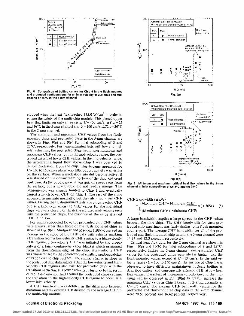
Figures 7(a) and 1(b) compare the boiling curves for Chip 1 in the flush-mounted and protruded configurations in the 5-mm channel, for inlet conditions of 50 cm/s and subcoolings of 3 and 25 °C, respectively. In general, data for the nucleate boiling regime for flush-mounted and protruded chips were similar. The nominal and adjusted single-phase heat transfer coefficients for the protruded chip were higher as discussed earlier. Figure 7(a) shows that out of the two protruded chip tests shown, the incipience of nucleate boiling occurred at considerably different heat fluxes. The heat flux at which boiling commenced typically varied between tests with similar conditions; however, the single-phase and nucleate boiling data points were repeatable as shown in Fig. 7(a). The lower of the two heat fluxes was near the flush-mounted value while the higher heat flux was almost two times larger. However, if the protruded chip heat flux is adjusted for the additional exposed surface area, the incipience heat fluxes would decrease by 28.6 percent. The wall temperatures for the protruded cases of Fig. 1(a) were slightly cooler than for the flush-mounted case during nucleate boiling, but there was no clear trend of the relative change in wall temperature throughout the data base. Some tests showed higher wall temperatures for the protruded chips compared to the flush-mounted chips while other tests showed lower or equal temperatures, as shown in Fig. 7(6). By adjusting the protruded chip heat flux data in Fig. 7(a) for the total exposed surface area, the protruded chip boiling curve moved closer to the flush-mounted chip boiling curve. Even with the area adjustment, the protruded and flush-mounted boiling curves remained on top of each other for the highly subcooled tests in Fig. 1(b) because of the near-vertical slope in the nucleate boiling data.
The tests in both Figs. 7(a) and 1(b) were for Chip 1 and consequently had the same local pressures. The local pressure was not the same for the downstream chips because the pressure drop across the multi-chip array was higher when the chips were protruded. As discussed earlier, the larger pressure drop spawned a lower local saturation temperature. This difference in pressure at downstream chip locations must be kept in mind when comparing flush-mounted and protruded data. At low velocities, the pressure drop was fairly small and, consequently, did not affect the boiling performance, but at high velocities, the pressure drop became quite large and the disparity between flush-mounted and protruded configurations became more evident. Figure 8 illustrates the boiling curves for Chip 9 for an inlet velocity of 200 cm/s at 36°C subcooling in the 5-mm channel. The pressure drop across the multi-chip array for the flush-mounted and protruded chips just prior to CHF was
10
Chip 1 U = 50 cm/s ATC1 = 3°C H = 5 mm
CHF Incipience
o D
A
m
q"
q"
q"
q'A
Flush-Mounted
1 mm Protruded
1 mm Protruded
1 mm Protruded
protruded, f lush-mounted 1 " ptm
, (lush-mounted • protruded
100
100
E u
10
Chip 1 U = 50 cm/s A T s u b = 25 °C H = 5 mm
protruded
o D
a
q"
q"
qA
Flush-Mounted
1 mm Protruded
1 mm Protruded
C H F Incipience
1 10 100 ATW ( °C )
Fig. 7(D)
Fig. 7 Comparison of boiling curves for Chip 1 in the flush-mounted and protruded configurations for an inlet velocity of 50 cm/s and sub-coolings of (a) 3°C and (b) 25°C in the 5-mm channel
0.0113 bar (0.166 psia) and 0.0401 bar (0.59 psia), respectively, which amounted to respective stream-wise saturation temperature decreases of 0.20 and 0.93°C. The protruded chip data in Fig. 8 are plotted using the heat flux based both on the chip base area and the total exposed chip surface area. Without the area adjustment, the protruded chip had a lower wall temperature. However by adjusting for only the surface area and not local pressure change, the boiling curves collapsed on top of each other. Because of the many and possibly competing phenomenon, a perfect comparison of the nucleate boiling data from downstream chips is very complex, and, the small differences in the raw data do not warrant an extensive investigation into all the detailed effects.
Critical Heat Flux. Critical heat flux values were measured during each experiment for all nine chips. This facilitated the identification of the first chip to undergo CHF (minimum CHF in array), last chip to undergo CHF (maximum CHF in array), and the order of CHF progression. During one of the high velocity and highly-subcooled tests, the thick-film resistor attached to Chip 1 failed when the heat flux surpassed 133.0 W/ cm2. The reproducibility of the data by the replacement chip was excellent; however, it was decided that the tests would be
84/Vo l . 115, MARCH 1993 Transactions of the ASME
Downloaded 27 Jul 2010 to 128.211.178.86. Redistribution subject to ASME license or copyright; see http://www.asme.org/terms/Terms_Use.cfm
100 r
I 10
Chip 9 U = 200 cm/s ATsub - 36 °C H = 5 mm
o a •
q"
q"
qi
Flush-Mounted
1 mm Protruded
1 mm Protruded
^
"protruded w
flush-mounted,.
• ° B 5 • a e
D mo o
d
1000
10
AT„(C
100
Fig. 8 Comparison of boiling curves for Chip 9 in the flush-mounted and protruded configurations for an inlet velocity of 200 cm/s and sub-cooling of 36°C in the 5-mm channel
stopped when the heat flux reached 135.0 W/cm2 in order to ensure the safety of the multi-chip module. This placed upper heat flux limits on only three tests: t /=400 cm/s, Arsub = 25 and 36°C in the 5-mm channel and U= 300 cm/s, Arsub = 36°C in the 2-mm channel.
The minimum and maximum CHF values from the flush-mounted chips and protruded chips in the 5-mm channel are shown in Figs. 9(a) and 9(6) for inlet subcooling of 3 and 25 °C, respectively. For near-saturated tests with low and high inlet velocities, the protruded chips had higher minimum and maximum CHF values, but in the mid-velocity range, the protruded chips had lower CHF values. In the mid-velocity range, the accelerating liquid flow above Chip 1 was observed to inhibit nucleation from the chip. This became apparent for U~ 100 to 150 cm/s where very little bubble activity was visible on the surface. When a nucleation site did become active, it was started on the downstream portion of the chip and crept upstream. As the bubble grew, it was quickly swept away from the surface, but a new bubble did not readily emerge. This phenomenon was visually limited to Chip 1 and eventually caused a much lower CHF on Chip 1. The rest of the chips appeared to nucleate normally, but they also had lower CHF values. During the flush-mounted tests, the chips reached CHF one at a time even when the CHF values for the individual chips were very close. For the near-saturated mid-velocity tests with the protruded chips, the majority of the chips attained CHF in unison.
For highly subcooled flow, the protruded chip CHF values were always larger than those of the flush mounted chips as shown in Fig. 9(b). Mudawar and Maddox (1989) observed an increase in the slope of the CHF data with velocity marking a transition from a low-velocity CHF regime to a high-velocity CHF regime. Low-velocity CHF was initiated by the propagation of a fairly continuous vapor blanket which originated from the downstream edge of the chip. High-velocity CHF was characterized by the coalescence of smaller, random patches of vapor on the chip surface. The similar change in slope in the protruded chip data suggests that the low-velocity and high-velocity CHF regimes also exist for protruded chips with the transition occurring at a lower velocity. This may be the result of the faster moving fluid around the protruded chips causing the transition to the high-velocity CHF regime to occur at a lower inlet velocity.
A CHF bandwidth was defined as the difference between minimum and maximum CHF divided by the average CHF in the multi-chip module.
100
10
Critical Heat Flux Bandwidth (Minimum and Maximum CHF in array)
Min.
O
D
Max.
®
S
Flush-Mounted
1 mm Protruded
H = 5 mm ATSub = 3 °C
Transition between the low-velocity CHF and high-velocity CHF regimes
/ \
S | « «
° °ooo0 • • • Protruded-
J° t itrnHpri -I
- Flush-Mounted
10 100
U (cm/s)
Fig. 9(a)
1000
1000
I = E
100
10
Critical Heat Flux Bandwidth (Minimum and Maximum CHF in array)
Min.
O
•
B
w o
Max.
a H
B D
O
Flush-Mounted
1 mm Protruded
H = 5 mm ATsub=25°C
C H F > 133.0 W/cm 2
Flush-Mountedn \ Protruded—X
g « flD!o°o 0 o o ,
m • D D :
o • o o
•
Transition between the low-velocity CHF and high-velocity CHF regimes
10 1000 100
U (cm/s)
Fig. 9(D)
Fig. 9 Minimum and maximum critical heat flux values in the 5-mm channel at inlet subcoolings of (a) 3°C and (b) 25°C
CHF Bandwidth (±x%) (Maximum CHF- Minimum CHF)
X(±50%) (5) - (Maximum CHF + Minimum CHF)
A large bandwidth implies a large spread in the CHF values between the nine chips. The CHF bandwidth for each protruded chip experiment was fairly similar to its flush-mounted counterpart. The average CHF bandwidth for all of the protruded and flush-mounted chip data in the 5-mm channel were 14.37 and 12.3 percent, respectively.
Critical heat flux data for the 2-mm channel are shown in Figs. 10(a) and 10(b) for inlet subcoolings of 3 and 25°C, respectively. Unlike the 5-mm channel, near-saturated CHF values for the protruded chips were always higher than the flush-mounted values except at t /= 13 cm/s. In the mid-velocity range (U~ 100 to 150 cm/s), the surface of Chip 1 was observed to have difficulty maintaining nucleate boiling as described earlier, and consequently attained CHF at low heat flux values. The effect of increasing velocity beyond the mid-range can be observed in Fig. 10(a) to greatly increase the minimum CHF value as Chip 1 began nucleating normally at U= 175 cm/s. The average CHF bandwidth values for the protruded and flush-mounted chip data in the 2-mm channel were 20.59 percent and 16.62 percent, respectively.
Journal of Electronic Packaging MARCH 1993, Vol. 115/85
Downloaded 27 Jul 2010 to 128.211.178.86. Redistribution subject to ASME license or copyright; see http://www.asme.org/terms/Terms_Use.cfm

1000
I 100
10
Crit ical Heat Flux Bandwidth (Min imum and Maximum CHF in array)
Min.
O
•
Max.
0
• Flush-Mounted
1 mm Protruded
H = 2 mm ATsub = 3 °C
Transition between the low-velocity CHF and high-velocity CHF regimes
B • _ a B " = D
O O u g o 0
10 100
U (cm/s)
Fig. 10(a)
1000
1000
E u g 100
: E
10
Critical Heat Flux Bandwidth (Minimum and Maximum CHF in array)
Max.
Flush-Mounted
1 mm Protruded
H = 2 mm ATsub=25°C
f F
e
o
\ / Transition between the low-velocity CHF and high-velocity CHF regimes
10 1000 100
U(cm/s)
Fig. 10(6)
Fig. 10 Minimum and maximum critical heat flux values in the 2-mm channel at inlet subcoolings of (a) 3°C and (b) 25°C
E u § 100
U = 300 cm/s H = 2 mm
• 0
Flush-Mounted
Protruded 1 mm
Hi (bar)
1.36
1.36
Pc9|bai)
1.28
0.986
A W , CO = W,-T,.i„
• 25.0
25.0
ATsub.c9 {°C}
= T„,.c9-T,.in
23.2
15.2
l r - 1
5 6
Chip
Fig. 11 Comparison of critical heat flux values for flush-mounted and protruded chips at inlet fluid conditions of 300 cm/s and 25°C sub-coolings in the 2-mm channel
10
10
10"
10
10"
Minimum CHF Protruded
H (mm)
2
5
Mean absolute error in the applicable range of the correlation
7.68%
10.7%
H(mm) 2 5 O D A
• B
A
ATsub (°C)
14 25 36
Applicable range for correlalion
x q m = 0.161 We
- Mudawar and Maddox (1989)
10' 10 10
We'1
10 10
Fig. 12 Comparison of nondimensional critical heat flux data for minimum critical heat flux in the multi-chip array in the 2-mm and 5-mm channels with the correlation of Mudawar and Maddox (1989)
Highly subcooled flow greatly increased the CHF values in the 2-mm channel as shown in Fig. 10(6). The slope change in the protruded chip data for the 2-mm channel also occurs at a lower velocity than the flush-mounted data. Note that the minimum CHF value for U= 300 cm/s is only slightly larger than for U= 200 cm/s while the maximum CHF value is considerably higher. A plausible explanation for this observation is the decrease in local subcooling as a result of the large stream-wise pressure drop across the chip array.
Figure 11 illustrates the protruded and flush-mounted CHF values for the nine chips at an inlet velocity of 300 cm/s and subcooling of 25°C. The stream-wise pressure drop prior to CHF across the protruded chips was 0.374 bar (5.5 psi) compared to 0.08 bar (1.17 psi) for the flush-mounted chips. Accounting only for the local pressure and not the temperature rise of the liquid, the local subcooling at Chip 9 was 23.2 and 15.2°C for the flush-mounted and protruded cases, respectively. This large decrease in subcooling most probably caused CHF to occur earlier on the downstream chips as observed for the majority of the protruded chip cases. Figure 11 also shows the CHF values for the flush-mounted chips have little stream-wise dependence while the CHF values for protruded chips show a definite decrease in the stream-wise direction.
As mentioned earlier, the order in which the chips attained CHF was recorded for all of the tests. Chips 8 and 9 were the
first chips to reach CHF, and Chips 1 and 2 were the last chips to reach CHF for all of the 2-mm channel tests except for the near-saturated tests in the mid-velocity range. As discussed earlier, Chip 1 was observed to have difficulty nucleating during those tests and consequently was the first chip to reach CHF. Trends in the progression of CHF in the 5-mm channel were not as clear as the 2-mm channel. For low and high velocity flow, the downstream chips tended to reach CHF first while the upstream-most chips tended to reach CHF last. In the mid-velocity range, the only noticeable trend was the low CHF value on Chip 1 for near-saturated conditions. For high inlet velocities, the CHF values of Chips 1 and 2 were noticeably higher, in both channels, than the other seven chips. It is possible that the enhancement mechanism observed for single-phase heat transfer on Chips 1 and 2 also increases their CHF values.
Figure 12 shows the data for the minimum protruded chip CHF, without area or velocity adjustments, comparing favorably with the flush-mounted CHF correlation of Mudawar and Maddox (1989). Over the correlation's applicable Weber number range, the mean absolute errors of the CHF data for the 14,25, and 36°C subcooled tests were 7.68 and 10.7 percent for the 2- and 5-mm data, respectively. Even though the CHF data for the protruded chips were higher, in general, than the flush-mounted values, Fig. 11, the correlation was able to predict the minimum CHF in the multi-chip array as shown
86/Vo l . 115, MARCH 1993 Transactions of the ASME
Downloaded 27 Jul 2010 to 128.211.178.86. Redistribution subject to ASME license or copyright; see http://www.asme.org/terms/Terms_Use.cfm

1000
5 ioo
10
Minimum Critical Heat FSux in array!
o D
Flush-Mounted Protruded 1 mm
H = 5 mm ATsub = 25 °C
u^mu
Transition between Ihe low-yelocvty CHF and high-velocity CHF regimes
/ \
% CP c b ^ 0 :
t t
10 100
UA(cm/s)
Fig. 13(a)
1000
1000
M
E o i 100
: E
10
Minimum Critical Heat Flux in array j
O O
Flush-Mounted Protruded 1 mm
-• . .«=,
H = 2 mm ATsub = 25 °C
-
O ° D D
°D°
•W-TV* 1
Transition between Ihe low-velocity CHF and high-velocity CHF regimes
/ \ :
! i o
o5° • e D r i
t t Protruded -J *— Flush-Mounted
10 100 UA(cm/s)
1000
Fig. 13(6)
Fig. 13 The effect of accounting for increases in surface area and liquid velocity due to protrusion on the minimum critical heat flux in the multi-chip array for an inlet subcooling of 25°C and channel heights of (4 5 mm and (b) 2 mm
10
10
<sl< 10
10
10""
Minimum CHF Protruded
H(mra)
2
5
Mean absolute error in the applicable range of the correlation
24.4%
3.98%
H(mm) 2 5 O D A
a B
A
ATsub(°C)
14 25 36
\ Range ot McGillis et al. data
- , " |Aw| = 0.254 W e " " 2
qm(^l = 0.125We
McGillis et al.. 1991
10' 10 10
We"1
10 10
Fig. 14 Comparison of nondimensional critical heat flux data for the minimum critical heat flux in the multi-chip array in the 2-mm and 5mm channels with the correlations of McGillis et al. (1991)
increases in exposed surface chip area and flow velocity above the chip. With these adjustments, the minimum CHF values become closer to the flush-mounted values; however, the maximum CHF values for many of the protruded cases would still be considerably higher than the flush-mounted data.
Figure 14 compares the minimum CHF data for the protruded chips to the curve fits of McGillis et al. (1991), Eqs. (2) and (3). The nondimensional CHF was adjusted only for the surface area change and not the flow area change to conform with the curve fits. Also the inlet subcooling was used in determining the dimensionless CHF values; McGillis et al. used a local liquid temperature in making the curve fits, but did not provide a clear method for calculating the local temperature. Over McGillis et al.'s Weber number range, the 2-mm channel data fell below the correlations with a mean absolute error of 24.4 percent while the 5-mm channel data were closer to the correlations with a mean absolute error of 3.98 percent. Extending the curve fit to higher Weber numbers than McGillis et al. tested show that the curve fits still overpredict the 2-mm channel data but intersect some of the 5-mm channel data.
in Fig. 12. The channel pressure drop was small over the applicable range of the correlation, thus the pressure effects on the local subcooling were also small. The relatively close agreement between the data and the correlation suggests that the correlation may be utilized in predicting the minimum CHF from slightly protruded chip arrays when no area or velocity adjustments are made to the data. Even though the correlation slightly overpredicts the minimum flush-mounted CHF data, the Mudawar and Maddox correlation was recommended for predicting the CHF values in flush-mounted chip arrays (Wil-lingham and Mudawar, 1992b) because of the relatively small CHF bandwidth, as shown by the small spread in the flush-mounted CHF values in Fig. 11. Care should be taken when utilizing the Mudawar and Maddox correlation for protruded chip arrays because some of the tests have fairly large CHF bandwidths, thus, the correlation only predicts the minimum CHF, which is most critical to the design of electronic cooling hardware.
Effect of Surf ace Area and Velocity Adjustments on Critical Heat Flux. The minimum CHF values for the highly-sub-cooled tests in the 5-mm and 2-mm channels are shown in Figs. 13(a) and 13(6) after adjusting the protruded data for the
Conclusions Forced-convection boiling experiments were conducted for
an array of nine chips protruding 1 mm into the liquid flow. Two channel heights were investigated (2 and 5 mm) in vertical upflow. Protrusion of the chips caused local increases in the velocity around the chip and increased the surface area of the chip exposed to the flow. The following key conclusions may be made.
(1) Upstream chips in both the 2-mm and the 5-mm channels had higher single-phase heat transfer coefficients than the rest of the chips. When the data were adjusted for the increases in surface area and velocity because of the protrusion, the majority of the chips showed good agreement with a correlation developed for flush-mounted, 5-mm channel data.
(2) For the data in each channel, the nucleate boiling regime was found to be insensitive to changes in inlet velocity and subcooling. Comparing boiling curves between upstream flush-mounted and protruded chips produced only minor differences when the data were referenced to the chip base area. Adjusting the chip data for the total exposed surface area associated with the protrusion showed an even better agreement between flush-mounted and protruded chips.
(3) Critical heat flux increased with both velocity and sub-
Journal of Electronic Packaging MARCH 1993, Vol. 115/87
Downloaded 27 Jul 2010 to 128.211.178.86. Redistribution subject to ASME license or copyright; see http://www.asme.org/terms/Terms_Use.cfm

cooling except for the near-saturated tests in the mid-velocity range ( t /~ 100 to 150 cm/s) where Chip 1 was observed to have difficulty nucleating. The CHF data were higher for the protruded chips as compared to flush-mounted chips. When the adjustments for exposed surface and flow area were made, the CHF values became closer. Chip 1 in the 5-mm channel and Chips 1 and 2 in the 2-mm channel had considerably higher CHF values than the rest of the chips for high velocity and/ or highly subcooled flow. This was attributed to the effective liquid contact with the most upstream chips since these chips were the first obstructions encountered by the liquid.
(4) Except for the near-saturated, mid-velocity tests, Chip 9 attained CHF first and Chip 1 attained CHF last in the 2-mm channel. This was attributed to the combination of two phenomena: the fairly large channel pressure drop reducing the local saturation temperature at Chip 9 by as much as 10°C, and the heat dissipation from the upstream chips causing the liquid temperature to increase in the stream-wise direction. The progression to CHF was not as distinct in the 5-mm channel where the pressure drop was not as large as in the 2-mm channel and the additional liquid helped reduce the thermal effect of the upstream chips.
(5) The correlations proposed by McGillis et al. (1991) for 0.8 mm protruded data accurately predicted the minimum CHF in the 5-mm channel over the recommended Weber number range but showed poorer agreement with the 2-mm channel data. The Mudawar and Maddox (1989) CHF correlation for a single flush-mounted heat source was found to accurately predict the minimum CHF value in both channels for the subcooled tests over the applicable Weber number range when no area or velocity adjustments were made to the data. The Mudawar and Maddox correlation is, therefore, recommended for predicting the minimum CHF in slightly protruded chip arrays.
Acknowledgment
Partial support of this work by the Naval Air Warfare Center Aircraft Division of Indianapolis through Contract N00163-91-C-0222 is gratefully acknowledged.
References Asako, Y., and Faghri, M., 1991, "Parametric Study of Turbulent Three-
Dimensional Heat Transfer of Arrays of Heated Blocks Encountered in Electronic Equipment," Heat Transfer in Electronic Equipment-1991, eds., A. Ortega, D. Agonafer and B. W. Webb, ASME HTD-Vol. 171, pp. 135-141.
Davalath, J., and Bayazitoglu, Y., 1987, "Forced Convection Cooling Across Rectangular Blocks," ASME Journal of Heat Transfer, Vol. 109, pp. 321-328.
Faghri, M., Lessman, R. C , Sridhar, S., Schmidt, R., and Asako, Y., 1989, "A Preliminary Experimental Study of Forced Air Cooling of Rectangular Blocks Encountered in Electronic Equipment," Collected Papers in Heat Transfer 1989, eds., W. J. Marner, T. S. Chen, M. Faghri, G. P. Peterson, T. H. Kuehn, M. B. Pate, R. L. Mahajan, and A. S. Lavine, ASME HTD-Vol. 123, pp. 1-6.
Garimella, S. V., and Eibeck, P. A., 1990, "Heat Transfer Characteristics of an Array of Protruding Elements in Single Phase Forced Convection," International Journal of Heat and Mass Transfer, Vol. 33, pp. 2659-2669.
Garimella, S. V., and Eibeck, P. A., 1991, "Fluid Dynamic Characteristics of the Flow Over an Array of Large Roughness Elements," ASME JOURNAL OF ELECTRONIC PACKAGING, Vol. 113, pp. 367-373.
Gersey, C. O., and Mudawar, I., 1992, "Effects of Orientation on Critical Heat Flux From Chip Arrays During Flow Boiling," ASME JOURNAL OF ELECTRONIC PACKAGING, Vol. 114, pp. 290-299.
Knight, R. W., and Crawford, M. E., 1988, "Numerical Prediction of Turbulent Flow and Heat Transfer in Channels With Periodically Varying Cross Sectional Area," Proceedings of the 1988 National Heat Transfer Conference, ed., H. R. Jacobs, ASME HTD-96, Vol. 1, Houston, TX, pp. 669-676.
Lee, T. Y., and Simon, T. W., 1989, "High-Heat Flux Forced Convection Boiling From Small Regions," Heat Transfer in Electronics 1989, ed., R. K. Shah, ASME HTD-Vol. I l l , pp. 7-16.
Maddox, D. E., and Mudawar, I., 1989, "Single and Two-Phase Convective Heat Transfer From Smooth and Enhanced Microelectronic Heat Sources in a Rectangular Channel," ASME Journal of Heat Transfer, Vol. I l l , pp. 1045-1052.
McEntire, A. B., and Webb, B. W., 1990, "Local Forced Convective Heat Transfer From Protruding and Flush-Mounted Two-Dimensional Discrete Heat Sources," International Journal of Heat and Mass Transfer, Vol. 33, pp. 1521-1533.
McGillis, W. R., Carey, V. P., and Strom, B. D., 1991, "Geometry Effects on Critical Heat Flux for Subcooled Convective Boiling From an Array of Heated Elements," ASME Journal of Heat Transfer, Vol. 113, pp. 463-471.
Moffat, R. J., and Ortega, A., 1988, "Direct Air-Cooling of Electronic Components," Advances in Thermal Modeling of Electronic Components and Systems, eds., A. Bar-Cohen and A. D. Kraus, Vol. 1, pp. 129-282.
Mudawar, 1., and Maddox, D. E., 1989, "Critical Heat Flux in Subcooled Flow Boiling of Fluorocarbon Liquid on a Simulated Electronic Chip in a Vertical Rectangular Channel," International Journal of Heat and Mass Transfer, Vol. 32, pp. 379-394.
Mudawar, I., and Maddox, D. E., 1990, "Enhancement of Critical Heat Flux From High Power Microelectronic Heat Sources in a Flow Channel," ASME JOURNAL OF ELECTRONIC PACKAGING, Vol. 112, pp. 241-248.
Roeller, P. T., Stevens, J., and Webb, B. W., 1990, "Heat Transfer and Turbulent Flow Characteristics of Isolated Three-Dimensional Protrusions in Channels," Thermal Modeling and Design of Electronic Systems and Devices, eds., R. A. Wirtz and G. L. Lehmann, ASME HTD-Vol. 153, pp. 7-13.
Rohsenow, W. M., 1982, "General Boiling," Handbook of Multiphase Systems, ed., G. Hestroni, Hemisphere Publishing Company, New York, pp. 6.5-6.26.
Samant, K. R., and Simon, T. W., 1989, "Heat Transfer From a Small Heated Region to R-113 and FC-72," ASME Journal of Heat Transfer, Vol. I l l , pp. 1053-1059.
Simons, R. E., 1987, "Direct Immersion Cooling: Past, Present, and Future," IBM Technical Report, TR 00.3465, International Business Machines Corp., Poughkeepsie, N.Y.
Sparrow, E. M., Niethammer, J. E., and Chaboki, A., 1982, "Heat Transfer and Pressure Drop Characteristics of Arrays of Rectangular Modules Encountered in Electronic Equipment,'' International Journal of Heat and Mass Transfer, Vol. 25, pp. 961-973.
Willingham, T. C , Gersey, C. O., and Mudawar, I., 1991, "Forced-Con-vective Boiling From an Array of In-Line Heat Sources in a Flow Channel," Proceedings of the ASME-JSME Thermal Engineering Joint Conference 1991, eds., J. R. Lloyd and Y. Kurosaki, Vol. 2, pp. 365-374, Reno, Nevada.
Willingham, T. C , and Mudawar, I., 1992a, "Channel Height Effects on Forced-Convection Boiling and Critical Heat Flux From a Linear Array of Discrete Heat Sources," International Journal of Heat and Mass Transfer, Vol. 35, pp. 1865-1880.
Willingham, T, C , and Mudawar, I., 1992b, "Forced-Convection Boiling and Critical Heat Flux From a Linear Array of Discrete Heat Sources," International Journal of Heat and Mass Transfer, Vol. 35, pp. 2879-2890.
88/Vo l . 115, MARCH 1993 Transactions of the ASME
Downloaded 27 Jul 2010 to 128.211.178.86. Redistribution subject to ASME license or copyright; see http://www.asme.org/terms/Terms_Use.cfm