Nuclear Electric Propulsion: A Better, Safer, Cheaper ... · NUCLEAR ELECTRIC PROPULSION: A...
18
NASA Technical Memorandum 106406 ! / Nuclear Electric Propulsion: A "Better, Safer, Cheaper" Transportation System for Human Exploration of Mars John S. Clark, Jeffrey A. George, Leon P. Gefert, Michael P. Doherty, and Robert J. Sefcik Lewis Research Center Cleveland, Ohio Prepared for the 1 lth Symposium on Space Nuclear Power and Propulsion Systems sponsored by the University of New Mexico Albuquerque, New Mexico, January 9-13, 1994 fil/ A (NASA-TM-I06406) NUCLEAR ELECTRIC PROPULSION: A BETTER, SAFER, CHEAPER TRANSPORTATION SYSTEM FOR HUMAN EXPLORATION OF MARS (NASA. Lewis Research Center) 17 p N94-28833 Unc|as G3/20 0002938
Transcript of Nuclear Electric Propulsion: A Better, Safer, Cheaper ... · NUCLEAR ELECTRIC PROPULSION: A...

NASA Technical Memorandum 106406
! /
Nuclear Electric Propulsion: A "Better, Safer,
Cheaper" Transportation System forHuman Exploration of Mars
John S. Clark, Jeffrey A. George, Leon P. Gefert,
Michael P. Doherty, and Robert J. SefcikLewis Research Center
Cleveland, Ohio
Prepared for the1 lth Symposium on Space Nuclear Power and Propulsion Systems
sponsored by the University of New Mexico
Albuquerque, New Mexico, January 9-13, 1994
fil/ A(NASA-TM-I06406) NUCLEAR ELECTRICPROPULSION: A BETTER, SAFER,
CHEAPER TRANSPORTATION SYSTEM FOR
HUMAN EXPLORATION OF MARS (NASA.
Lewis Research Center) 17 p
N94-28833
Unc|as
G3/20 0002938


NUCLEAR ELECTRIC PROPULSION:
A "BETTER, SAFER, CHEAPER" TRANSPORTATION SYSTEMFOR HUMAN EXPLORATION OF MARS
John S. Clark, Jeffrey A. George, Leon P. Gefert, Michael P. Doherty, and Robert J. SefcikNASA Lewis Research Center
Cleveland, OH 44135
(216) 977-7108
Abstract
NASA has completed a preliminary mission and systems study of nuclear electric propulsion (NEP) systems
for "split-sprint" human exploration and related robotic cargo missions to Mars. This paper describes thestudy, the mission architecture selected, the NEP system and technology development needs, proposed
development schedules, and estimated development costs. Since current administration policy makers have
delayed funding for key technology development activities that could make Mars exploration missions areality in the near future, NASA will have time to evaluate various alternate mission options, and it appears
prudent to ensure that Mars mission plans focus on astronaut and mission safety, while reducing costs to
acceptable levels. The split-sprint nuclear electric propulsion system offers trip times comparable to nuclear
thermal propulsion (NTP) systems, while providing mission abort opportunities that are not possible with"reference" mission architectures. Thus, NEP systems offer short transit times for the astronauts, reducing the
exposure of the crew to intergalactic cosmic radiation. The high specific impulse of the NEP system, which
leads to very low propellant requirements, results in significantly lower "initial mass in low earth orbit"
(IMLEO). Launch vehicle packaging studies show that the NEP system can be launched, assembled, and
deployed, with about one less 240-metric-ton heavy lift launch vehicle (HLLV) per mission opportunity - a
very large cost savings! Technology development cost of the nuclear reactor for an NEP system would be
shared with the proposed nuclear surface power systems, since nuclear systems will be required to provide
substantial electrical power on the surface of Mars. The NEP development project plan proposed includes
evolutionary technology development for nuclear electric propulsion systems that expands upon SP-100
(Space Power - 100 kw e) technology that has been developed for lunar and Mars surface nuclear power, and
small NEP systems for interplanetary probes. System upgrades are expected to evolve that will result in even
shorter trip times, improved payload capabilities, and enhanced safety and reliability. Non-nuclear technology
development for the NEP system is estimated to cost about $721 M (1993 $). Nuclear technology
development costs are not included in the costs in this report, since these costs will be incurred in the nuclear
surface power development program. NEP Phase A/B studies are estimated to cost about $154 M. Flight
system hardware development (Phase C/D) is estimated to cost about $2.8 B, and fabrication of flighthardware is estimated to be about $7.8 B for four mission opportunities in 2009, 2011, 2014, and 2016.
INTRODUCTION
Nuclear propulsion has been identified as a critical technology for future space exploration missions (Cohen,
1989). Gilland (1991a, 1991b, and 1992) and George (George et ai, 1991, 1992, and George 1991) have
performed extensive studies of nuclear electric propulsion systems for manned exploration missions. TheNASA Lewis Research Center's Nuclear Propulsion Office (NPO) has conducted NEP studies and technology
development since early in 1990 to support a human presence on the Mars surface in 2019, as recommended
by President Bush. Doherty and Hoicomb (1993) have summarized the recommendations for NEP technology
development made by an interagency panel of NEP experts. NEP systems are also being considered forrobotic outer planet science missions. These missions and NEP technology developments are discussed in theConference Publication from the Nuclear Propulsion Technical Interchange Meeting held in Sandusky, OH
(NP-TIM, 1993). Because of the very high Isp (specific impulse) which leads to low propellant requirements,
NEP systems are believed to be enabling for a wide range of possible future planetary missions - bothmanned and robotic.

Propulsion System Selection Criteria
Prior to selecting a propulsion system for a specific mission, it is important to develop selection criteria and
appropriate weighting factors to compare various options on a consistent basis. For example, for a piloted
mission to Mars, a number of propulsion system options exist, including: chemicaFaerobrake systems (Cohen,
1989); nuclear thermal propulsion systems (Borowski 1991a, 1991b, Borowski and Alexander 1992, 1993,
Borowski et al 1992); nuclear electric propulsion systems (Gilland 1991a, 1991b, and 1992); and a
"reference" system that utilizes a nuclear thermal rocket (NTR) for earth departure, a Mars-capture-aerobrake,
and a liquid oxygen/methane (Lox/CH4) chemical rocket stage for return to earth (Duke 1993).
Several possible criteria that could be used to compare these systems include, "better, safer, and cheaper."Metrics must be selected, however, to measure each of the proposed systems against these criteria. For
example, "better, safer, and cheaper" could be measured by:
1. Initial mass in low earth orbit (IMLEO): Since this mass (and volume) largely determines the number
of heavy lift launch vehicles (HLLV) required to complete the mission, and because the cost involved is on
the order of $1 billion per launch, this will be a very important metric;
2. Piloted Trip Time: Since the best way to limit the exposure of the astronauts to high energy,intergalactic cosmic radiation is to reduce the time that they spend traveling between earth and Mars and
returning, systems that offer reduced trip times are significantly better and safer than slower systems;
3. Safety and Reliability: Since mission failure could result in loss of crew, system safety and reliability
will be a critical selection criteria. Obviously, tradeoffs must be made to optimize reliability and safety with
robust systems versus redundancy and cost;
4. Abort Options: Some systems offer significantly improved abort options compared to other systems
and this metric will be very important. Since loss of crew is an unacceptable mission scenario, systems that
permit a safe return to earth under all foreseeable accident possibilities would be strongly favored over
missions that include significant crew risk;
5. Enhanced Science Options: Some systems could offer significantly richer science return as a result of
the characteristics of the systems involved. For example, a system that is "power-rich" could enable greater
excavation capability, longer crew excursions, more laboratory equipment utilization, and so forth.
Maximum science return could be a selection criteria for the ambitious missions envisioned;
6. Environmental Contamination: Environmental contamination cannot be tolerated, whether on a
planetary body, or as part of a ground testing program on the earth, or in space. Mission plans must include
acceptable end-of-life disposal for all space hardware, so as not to generate unwanted space debris. This will
be a particularly sensitive issue with nuclear systems;
7. Minimum costs: All mission costs must be considered, and in general the more complex the system,
the higher the cost. Technology development cost will be a strong function of technology-readiness, and must
be traded off against operations cost and technical risk. Detailed development cost will be very important,
and flight qualification must be included; these costs will vary from system to system. Total Life cycle cost
may be the appropriate metric, and is difficult to predict in advance; and
8. "Unexpected costs:" Unexpected costs probably should also be considered, since these costs may in fact
be more important than any of the expected costs. As an example of an unexpected cost, suppose that a
nuclear system is planned for the earth departure maneuver, and an unexpected accident occurs that threatens
re-entry of the nuclear system into the earth atmosphere. The unexpected cost would be the cost of launching
other missions to intercept the system and whatever else is necessary to preclude atmospheric re-entry.
Another unexpected cost example would be the cost of cleanup if a nuclear system did inadvertently re-enter
the earth atmosphere and either disperse over a large area or impact the earth intact. These unexpected costs
2

must be traded against the probability of occurrence and the benefit to the mission. Also, adverse public
opinion regarding possible nuclear system accidents in space could delay or terminate the program.
These proposed metrics are some typical examples of the types of metrics that must be considered in the
selection of a propulsion system for a complex mission of this type. Many other metrics will undoubtedly be
important as well. A formal decision-making process, such as Quality Functional Deployment - QFD
(Bossert 1991, Hauser and Clausing 1988) or the Analytical Hierarchy Process - AHP (Saaty 1980), will be
required to (1) identify all the appropriate metrics, (2) apply appropriate weighting factors to each metric, (3)
reach consensus on metric scoring for various options, and (4) finally, select the system based on all weighted
variables. This formal process will require an appropriate interdisciplinary team of people and a long,
consensus-building process to evolve to the optimum selection decision.
REFERENCE MISSION ARCHITECTURE
Duke, et al (1993) has described several Mars exploration mission architectures, and a set of ground rules by
which these architectures can be compared. The current reference mission architecture (as defined by the
former Exploration Program Office (EXPO) at NASA Johnson Space Center) is shown schematically in
\NTR 1}dl Slagc/7 \
Ma_rs Orbit C,'lpture/I)e_,*-nl Aerobrakc .---/
ECRV _ 2-1,ev¢l _,,rf_c Ilabita__
Ascent Stage--_._
IX.scent Stage -11 1,11,',1 I_k
LOx/CII4 TEl St_,e -_
_m
Mars Orbil ........ _lll[
!11/
lrartsit Ilabitat. 35 Ml" -
SurFace Rover &
.2_ . T HUN Milts Surface - " NOT TO SCAt.E!
Figure 1. Human Mars Exploration Reference Mission.
Figure 1, and is described in Table I (Duke 1993). This reference architecture provides the mission objectives
and common hardware requirements whereby alternative concepts can be compared on a consistent basis.
These common requirements are used in this study to evaluate nuclear electric propulsion to perform the same
split-sprint mission. Thus, the functionality of the NEP mission must be at least as good as the referencemission.
Common hardware includes: 225 - 240 MT (to low earth orbit) HLLVs; (3) cargo landers (50 MT cargo
delivered to Mars each), including an ascent/descent module that includes processing equipment for in-situresource utilization, a two-level, 50-MT surface habitat, and a surface rover/science equipment module. Each
of these modules are delivered to the Mars surface by a nuclear thermal rocket (NTR) Trans-Mars-Injection
(TMI) stage, a 29 MT Mars descent aerobrake/parachute system and descent stage designed for a final descent
velocity change (delta-V) of 500 m/see. The crew travels to Mars in a 50 MT 2-level surface habitat via an
NTR TMI stage, a Mars aerocapture aerobrake, and a Mars descent stage. The crew returns to a LOx/CH4
Trans-Earth-lnjection (TEl) stage, including a 35 MT transit habitat, in the 7 MT Earth Crew Return Vehicle
(ECRV) for return to earth.
3

There are several issues with respect to the reference missionthat should be discussed and (eventually) resolved. First, the
heavy lift launch vehicle does not currently exist. Therefore, the
lifting capacity, 225-240 MT remains arbitrary. Current studiesare also evaluating a 100 MT class HLLV, which would require
some low earth orbit rendezvous and docking for the reference
mission. For this study, a reference 240 MT HHLV is assumed.
Second, the assumed masses for the transit return habitat
(35 MT) and the surface habitat (50 MT) are not well def'med.These masses are critical to the entire architecture of the
mission.
The nuclear thermal rocket TMI stage does not currently exist,
and the cost of ground testing NTR engines in an
environmentally acceptable manner remains an issue. Open-air
testing of NTR engines will certainly not be acceptable.
The reference mission includes a single aerobrake structure to
perform both the Mars orbit capture maneuver and initialdeceleration to the Mars landing site. This aerocapmre
maneuver must be successfully accomplished for both the
relatively low velocity cargo payloads and the very high velocity
piloted payloads. Successful demonstration of this capability in
the Mars atmosphere will undoubtedly be an important (and high
cost) element of an aerobrake technology validation experiment.
There is considerable uncertainty in the estimates of the
velocity change to be accomplished with the final Mars descent
stage. Estimates have ranged from 950 meters/second to as lowas 300 meters/second. The current reference mission estimate of
500 meters/second is used for this study.
Finally, the reference "abort to Mars surface" strategy requiresthat redundant surface habitats be available at the site to provide
consumables in case the crew is unable to return to the TEl
stage and are thus required to stay on Mars until a rescuemission can be sent. Thus, the number of expeditions to a
particular site becomes important in determining the number of
HLLVs required. For the reference mission, if each expeditionis to a different site, five HLLVs would be required per mission
opportunity. If two expeditions go to the same site, a total ofnine HLLVs would be required, and so forth. For this study and
the reference mission, it is assumed that two expeditions go to
each site.
Table I. Reference Mission Description.
Split-Sprint: Cargo first, autonomousdeployment, fast piloted trip
ISRU: In-Sire Resource Utilization
(ISRU) to produce propellantfor Mars ascent
Mission Designed for Worst Opportunity:200___g8:(4) HLLV Cargo flights
344 day transit times(3) autonomous landers to Mars50 MT per land_.
- LOx/CH_ Production Plant + power- Double Surface Habitat (50 MT)- Surface Rover + Equipment
(1) LOx/CH_ TEI stage to Mars Orbit- Single Transit HabRat (35 MT)
2010: (1) Piloted mission- Crew of six to Mars orbit
- 180 day transit (zero-G) each way- 540 day stay on Mars
225 MT HLLVs to LEO (407 kin):50 ft dia. x 100 ft (15.2m x 30.4m)No Earth Orbit Rendezvous or Assembly
NTR TMI Transfer Stage: (2) 50,000 lbt engines,Specific Impulse, 19 = 925 secondsThrust/Weight = 4.3 with shielding,Disposal to Heliocentric Orbit, 1.2 AU
Aeroeapture in Mars Orbit:(250 x 34,000 kin, 1 sol, 40* incl.)
Aerobrake Descent at 30 ° Latitude:! 5 % Aerobrake/Parachute descent
Mars Final Descent Stage: 90,000f lb thrustStorable Solid Propellant or LOx/CH4
19 = 342 secondsMars Ascent Stage:
In-Situ Produced Propellant (LOx/CH4)30,000 lbf Thrust, 19 = 376 sec.Common Ascent Crew Cabin/Earth Crew
Return Vehicle (ECRV)Direct Earth Entry in ECRV:
Transit Habitat Disposal to Heliocentric OrbitAbort Strategies:Outbound: to Mars SurfaceAt Mars: Backup Ascent Stage & Propellent
Production (arrives several months aftercrew arrives)
Inbound: Backup LOx]CH4 stage (arrives severalmonths after crew ascends to Mars orbit)
NEP STUDY
The objectives of the NEP split-sprint architecture study were (1) to determine if a nuclear electric
propulsion system could be a viable alternative for human Mars exploration missions, (2) to develop aneffective NEP implementation and operations strategy, evaluate the system technology requirements, mass
estimates and performance parameters, and (3) to provide a first-order estimate of NEP development plans,
schedules, and costs.

]'he study was performed by staff at the Nuclear Propulsion Office and the Advanced Space Analysis Office
at Lewis, with support from NEP technologists at Lewis and JPL. Development cost estimates were made by
the Cost Analysis Office at Lewis using Lewis and NASA cost models.
The following groundrules were used to conduct the study:
(1) The reference mission functionality had to be maintained; that is, the necessary infrastructure
(150 MT cargo + crew) had to be delivered to the Mars surface on time;
(2) Crew safety and hardware reliability had to be maximized;
(3) The number and/or size of HLLVs had to be minimized to reduce launch costs;
(4) Space-based operations should be kept as simple as possible;
(5) Piloted trip time must be minimized to reduce crew exposure to harmful intergalactic cosmic
radiation; and
(6) Life cycle costs must be minimized.
The estimated development costs presented in this report are an important part of the life cycle cost;
however, previous studies have shown that transportation costs are the main cost driver for space exploration.
Additional studies are underway at NASA in the New Initiatives Office at Johnson Space Center, to compare
estimated life cycle costs of various alternative scenarios (Duke 1993).
DESCRIPTION OF NEP ARCHITECTURE
The NEP mission architecture selected is shown schematically in Figure 2. A nuclear electric propulsion
system is used in place of the NTR TMI stage and the TEl LOx/CH4 stage. NEP propulsive braking is also
used to replace the aerocapture Mars orbit insertion maneuver of the reference mission.
2007 2009 2011 2014 2016
¢2_ ManAseent/l_.semtVehide [] CaewTramitHabitat _ MarsAereb_e_tSyste_n
Rover/Lab Surface Unit _ NEP Power Module _, ECRV
Figure 2. NEP Mission Architecture Shown for Four Mission Opportunities.

Ca_o
A 4 MW e reactor/propulsion module is used to transfer cargo on a minimum energy trajectory from low
earth orbit (407 km) to Mars. The NEP system propulsively brakes to Mars orbit capture. As with the
reference architecture, an aerodescent and parachute system is used to decelerate each cargo payload to 500-
meters-per-second descent velocity for which the Mars descent engine is designed. The aerodescent and
parachute system are then discarded, and descent engines slow the cargo to hover over the landing site and
land autonomously. The NEP cargo stages deliver a surface rover and its related equipment, and two surfacehabitats. The second habitat is a backup for the first crew in case a problem develops with the ascent vehicle
and the crew is required to stay on the Mars surface until a rescue mission can be sent on the next mission
opportunity; this habitat would also be used by the crew on the next mission. The NEP cargo stage alsodelivers a Mars descent/ascent vehicle (without ECRV) to high Mars orbit where it waits for the crew arrival.
Once emptied, the NEP propellant tanks are dropped in space to reduce energy requirements - at Earth escape,
and upon arrival at high Mars orbit.
In-situ resource utilization (ISRU), LOx/CH 4, for the ascent engine, is replaced in the NEP scenario by a
solid propellant ascent stage for several reasons: (1) mass estimates for ISRU versus solid propellants are
approximately the same; (2) solid propellants are "off-the-shelf," robust, and simpler (hence, probably morereliable); and (3) the minimum energy trajectories selected for the NEP cargo missions arrive at Mars too late
to produce return propellant prior to lifioff of the crew from earth. A smaller ISRU unit may be included onthe ascent/descent module if the surface rover is to be powered by LOx/CH 4, or if the ISRU is to be used to
provide oxygen for the crew or crop production.
After the NEP systems deploy their cargo at Mars, the NEP module restarts and boosts the vehicle to a
heliocentric disposal orbit between earth and Mars (1.3 AU). These systems could perform a very useful
communications relay function at this location, insuring that there would be no periods of communicationsblackout with the crew on the surface of Mars. Solar flare detectors could also be mounted on the vehicle at
this location to warn space explorers. Optionally, the NEP propulsion module could be left in Mars orbit as a
backup propulsion module for subsequent flights.
C Few
Two 4-MW e reactor/propulsion modules are used to transfer the crew from earth orbit to Mars on a fast
trajectory. One HLLV lifts the NEP propulsion system to low earth orbit. The two power modules are
deployed in low earth orbit, and spiral to a high earth orbit (beyond the Van Allen radiation belts) to await
the arrival of the crew. A second (lightly loaded) HLLV lifts the crew directly to high earth orbit in a crewcommand module that includes a 35 MT transfer habitat (with consumables for both transit to Mars and
return to the earth), and the ECRV (7 MT). The transfer habitat module (with crew inside) then
autonomously docks with the 8-MWe NEP system in high earth orbit, the NEP system is started, and the
astronauts continue their journey to Mars. The relatively low mass of the transfer vehicle enables fast transit
times with the low thrust NEP system.
The 8-MW_ NEP system is also used to propulsively brake into a high Mars orbit (HMO). There, the crewtransfers to the ECRV, and the ECRV docks with the descent/ascent stage delivered on the earlier cargo
flight, and continues down to the Mars surface to conduct their expedition. The 8 MWe NEP crew transfer
habitat remains in high Mars orbit until the crew completes their surface mission and then returns via the
ECRV on the ascent stage, for a return rendezvous with the NEP transfer stage. The crew transfers back tothe transit habitat and Trans-Earth Injection (TEl) is then accomplished by the NEP transfer stage. When the
maximum ECRV earth-entry velocity of 9.4 km/seeond is reached, the NEP system is turned off, the transit
habitat and ECRV separate from the NEP stage; the crew coasts to a direct-entry ocean splashdown in the
ECRV. The NEP stage decelerates to capture in high earth orbit (100,000 km), and then spirals down to low
earth orbit (1000 km for resupply) for subsequent refitting for the next mission. This refitting includes NEP
propellant tanks and thrusters for the next piloted trip. Upon completion of the retrofitting, the NEP stage
spirals out to high earth orbit to await the arrival of the next crew.

The HLLV launch manifests for the 2009, 2011, 2014 and
2016 mission opportunities are shown in Table II. The most
heavily loaded launch at 240 MT is the "Piloted A" launch that
sends the NEP power and propulsion system to low earth orbit.Notice that the "Piloted B" launch carries the crew in the 35 MT
tramit habitat with an earth crew return vehicle (ECRV) to high
earth orbit for rendezvous with the assembled NEP
transportation stage. It may be possible to use a smaller launchvehicle for this earth-to-orbit crew ascent leg of the mission.
Attaching the ECRV to this launch permits a direct return to
earth if a problem develops prior to earth escape. Assuming that
two crews visit each expedition site (as discussed above), the
reference architecture requires 4 1/2 HLLVs per mission
opportunity (9 HLLV for two opportunities). The NEParchitecture described above requires only 3 1/2 HLLVs per
mission opportunity - a savings of one HLLV every 26 months.Since each HLLV will probably cost $1 billion or more, this
represents a very large cost savings!
NEP SYSTEM
The NEP piloted vehicle configuration is shown schematically
in Figure 3. Two 4 MW c nuclear power systems provide the
thermal energy. The cargo propulsion and power modules are
exactly the same, but only one module is used for the cargo
flights. SP-100 reactor technology is assumed - scaled up in
power from 2.4 MW 1to 24 MW, (100 kw_ to 4 MW_), with a
5-year full power life. Each reactor is separated from the crew
by shielding and a 60-meter long boom - limiting crew radiationfrom the reactors to less than 5 Rem/year. The uranium nitride
pin-type fuel is cooled with liquid lithium in a fast reactor
configuration. Reactor outlet temperature is 1375 K. A
potassium-rankine turbine-alternator system is used (turbine inlet
temperature 1300 K) to generate electrical power at 1400 volts
EAI_Tll CREW
c_os.c,,xaor_u_,r _=_Z/Xx \
RADIATORS
PO_VE_. COK_E_IOf_
Figure 3. 8 MW_ Piloted Mars Vehicle.
Table II. HLLV Launch Manifests for
Four NEP Mission Opportunities to Mars.
I..l_mcJl_ HLL¥" I llothdo: I _ (MII_:
Yoar:. " I
2007 _ A R_c&lJIb/A4Wlldl_om 79
4 I,Iwe Cmqlo Pmmr S,/_m_ 42
crop Pm_ mcx_ asTotal: 201;
_B (2_ _ I.Imbi'm_d,q_moud_ee 1as
_t 79
Torah 237
2009 Piloted A 8 MWe Piloted Pow_ S_tem 79
I:_ Prop_ M_e 151
Total: 240
B Tmrvr.it H_ailat 35
7Total: 42 "
2009 C4_o A Rov_Sl.s_od_ce_ 794 MWe C_ Pm_x Sysmm 42
Total: 206
G.,eu_o B Surloce H_biltrd_scent 79
(2) Ascent/Descent 158
Total: 23"/
20'_ 1 f:_tKl A 8 )&We P_lolod POw_ Syl;Iorn 79
Pilowd I_o_ulsX)n Module 161
Total: 240
Pilomd B Tmm._t Hab,_mt 35
B:_ 7Total: 42 "
20 '_"I Cargo A _& LalYAeco<_mcen_ 79
4 MWe C4r_o Powe¢ Syssem 42
C4_o Pro_JLS,o_ kk_Ou_e 85
Total: 206
C_r_o B Surlo¢e Ha_,/Ae*oOescent 79
AscemVDescanl 79
Rover & La b/Ae_odesce r_ 79
Total: 237
201 _. Pitote0 A _ Pdote_ F_Is,on Module 240
Piloted B Trar_il Habibl! 35
B:RV 7TOtlI; 42 *
2016 I_lo'le¢ A F_l_otedPTo0umonModule 240
Piloted B Tmr_t Habitat 35
B:RV 7Total: 42 "
• Mess ,s *r, jeoed dlre¢_ to _ ira o_t
mu:kr., 0 I',r,LLV pe_lom=ce lot =I_.
and 2 kHz, and transmit the electricity to the
power conditioning equipment. Three 2-MW¢
power conversion loops are included for a
50-percent redundancy of the powerconversion system. Carbon-carbon-potassium
heat pipe radiators reject waste heat from the
rankine cycle at temperatures approaching the
975 K condensing temperature of the
potassium. Mass estimates for the radiator
are based on 5 kg/m 2 for the radiators andcondensers, which is consistent with SP-100
technology. An additional 1 k_m 2 is
included for the tapered shear flow condenser
duct running along the base of each radiator
"wing." In the power management anddistribution (PMAD) system, high temperature
(450 K) electronics convert the electricity to
the form required for the banks of 1000 kWion thrusters . Two PMAD architectures were
investigated. Generation and transmission at
the 1400 volt load requirement proved to be lighter than generation and transmission at 5000 volts. Although
the high voltage option would have high Wansmission efficiency, this was more than offset by the mmsformer
mass required. The propellants assumed are krypton for the piloted flights and argon for the cargo flights.
Table HI. NEP system Mass Breakdown
(kg) for 2009 Mission Oppormnir
Power Module
Shield
Pow¢= _
Radia_
Power Conditioamg
Total
]Io. Propulsion Module
_/Pow¢= Processing
empe_tT_agcS_mreTotal
Payload
Total
CARGOVEHICLEI x d MWe
3,810!
9,76C
7,s_4,18_
11,25(]
41,51@
3 x d MWe
7,20_65,6_
6,57_
6.O0085,420
316,000
442,93O
PILOTEDVEHICLE2 x 4 MWe
7.62£
19,52£L5.72C$36C
79,121]
4 x 4 MW¢
9.60_
137.46_
13.75(3
162,01@
42.00fl
283.LM
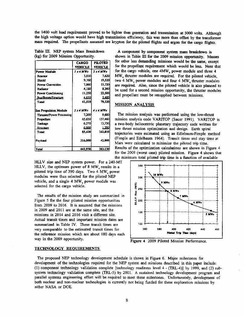
A component by component system mass breakdown is
shown in Table HI for the 2009 mission opportunity. Masses
for other less demanding missions would be the same, except
for the propellant requirement which would be less. Note that
for the cargo vehicle, one 4MW e power module and three 4
MWe thruster modules are required. For the piloted vehicle,
two 4 MW, power modules and four 4 MW c thruster modules
are required. Also, since the piloted vehicle is also planned to
be used for a second mission opportunity, the thruster modulesand propellant must be resupplied between missions.
MISSION ANALYSIS
The mission analysis was performed using the low-thrust
mission analysis code VARITOP (Sauer 1991). VARITOP is
a two-body heliocentric planetary trajectory code written for
low thrust mission optimization and design. Earth spiral
trajectories were estimated using an Edlebaum-Fimple method
(Fimple and Edelbaum 1964). Transit times and stay time at
Mars were calculated to minimize the piloted trip time.
Results of the optimization calculations are shown in Figure 4for the 2009 (worst case) piloted mission. Figure 4 shows that
the minimum total piloted trip time is a function of available
HLLV size and NEP system power. For a 240-MT
HLLV, the optimum power of 8 MW, results in a
piloted trip time of 390 days. Two 4 MW, powermodule, s were thus selected for the piloted NEP
vehicle, and a single 4 MW c power module was
selected for the cargo vehicle.
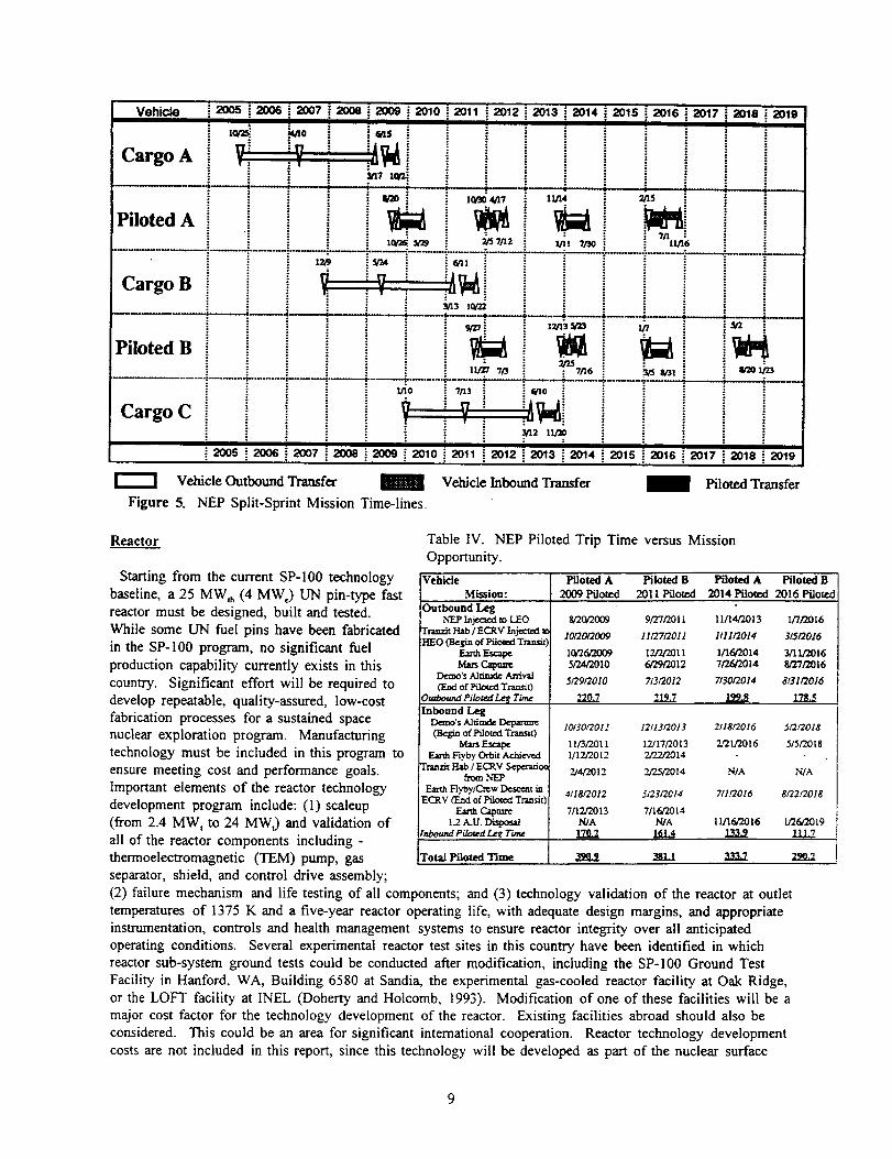
The results of the mission study are summarized in
Figure 5 for the four piloted mission opportunitiesfrom 2009 to 2016. It is assumed that the missions
in 2009 and 2011 are at the same site, and themissions in 2014 and 2016 visit a different site.
Actual transit times and important mission dates aresummarized in Table IV. These transit times are
very comparable to the estimated transit times for
the reference mission which are about 180 days each
way in the 2009 opportunity.
,oo_------_-%_-*-..........-................-..............i...........
250 ..........
_200
150
aso sso 4OO 420 440 ,_0_ That (_)
Figure 4 2009 Piloted Mission Performance.
TECHNOLOGY REQUIREMENTS
The proposed NEP technology development schedule is shown in Figure 6. Major milestones for
development of the technologies required for the NEP system and missions described in this paper include:
(1) component technology validation complete [technology readiness level 4 - (TRL-4)] by 1999, and (2) sub-
system technology validation complete (TRL-5) by 2001. A sustained technology development program and
parallel systems engineering effort will be required to meet these milestones. Unfortunately, development of
both nuclear and non-nuclear technologies is currently not being funded for these exploration missions byeither NASA or DOE.
Vehicle
CargoA i V: :!i
Piloted A
i2005 i2006i2007 !2008
!
Cargo B
Piloted B
Cargo C
2009 i 2010 _ 2011
:
V" : v
_12 _13
t :: = ;
2014 2015 2016 2018
lOp_o4/17
_/s 7n2
f_ll
N13 1o/22
11/14
1111 7/30 ll_r16
- 12/13_¢23 I/7
llrZY 7/3 : 7/16
"i.................................. ....• " .: il
i 3n2 lxt_
i 2005 2006 2007 2008 2009 2010 2011 2012 _ 2013 i 2014 2015 2016i
Vehicle Outbound Transfe_ ::..........:::::::::::::::::::::::::
Figure 5. NEP Split-Sprint Mission Time-lines.
Vehicle Inbound Transfer
w31 _1_23
2019
2017 2018 2019
Piloted Transfer
Reactor
Starting from the current SP-100 technology
baseline, a 25 MW_h (4 MW,) UN pin-type fast
reactor must be designed, built and tested.
While some UN fuel pins have been fabricated
in the SP-100 program, no significant fuel
production capability currently exists in this
country. Significant effort will be required to
develop repeatable, quality-assured, low-cost
fabrication processes for a sustained space
nuclear exploration program. Manufacturing
technology must be included in this program to
ensure meeting cost and performance goals.
Important elements of the reactor technology
development program include: (1)scaleup
(from 2.4 MW, to 24 MWt) and validation of
all of the reactor components including -
thermoelectromagnetic (TEM) pump, gas
separator, shield, and control drive assembly;
Table IV. NEP Piloted Trip Time versus Mission
Opportunity.
Vehicle Piloted A Piloted B Piloted A Piloted BMission: 2009 Piloted 2011 Piloted 2014 Piloted 2016 Pilotec
Outbound LegNEPI_ject_ _ LEO
TramfitI-lab/ECRV Injected _oHEO(BeginofPilots[Tntmit)i
mrs Cap_Demo'sAlfiaxle A,rtiv_(Fad of _ Tran_x)
Inbound Leg£_'s Alfitad_Deparm_(Beg_ of Piloted Txamat)
MarsEscapeEar,.hFlyby Orbit Achieved
TranzitHab / ECRV 5¢_o¢fax)mN'EP
Ea_ Flyby/Crew Des_cmtinECRV(Fad of Piloted Transit)
Farm C_aa_L2 A.U. Disgo_
rnboundPiloted Le_.T'u,n¢
g/20/2(X_9 9/27/2011 1111442013 I/7/2016
101201"2009 1112712011 1111/2014 3[512016
10/26/2009 12/2/2011 1/16/2014 3/11/20165/7A/2010 6/29/2012 7/'26/2014 8/27/2016
5/'29/'2010 7t31"2012 7/30/2014 8/311"2016
".2O.7 ,,19.,2 _99.S 12_
1013012011 12/1312013 211812016 51212018
11/3/2011 12/17/2013 2/21/2016 5/5/'20181/12/2012 2/22/2014
_4/2012 2/25/2014 NIA N/A
4118/2012 512312014 7/1/2016 8/22/'2018
7112/2013 7/16/20t4N/A N/A 11/16/2016 1/26,"2019
TotalPiloted Time 390.9 _ 333.7
(2) failure mechanism and life testing of all components; and (3) technology validation of the reactor at outlet
temperatures of 1375 K and a five-year reactor operating life, with adequate design margins, and appropriate
instrumentation, controls and health management systems to ensure reactor integrity over all anticipated
operating conditions. Several experimental reactor test sites in this country have been identified in which
reactor sub-system ground tests could be conducted after modification, including the SP-100 Ground Test
Facility in Hanford, WA, Building 6580 at Sandia, the experimental gas-cooled reactor facility at Oak Ridge,
or the LOFT facility at INEL (Doherty and Holcomb, 1993). Modification of one of these facilities will be a
major cost factor for the technology development of the reactor. Existing facilities abroad should also be
considered. This could be an area for significant international cooperation. Reactor technology development
costs are not included in this report, since this technology will be developed as part of the nuclear surface

Activity Name I 1994 ] 1995
TECHNOLOGY
I 1996 I 1997 I 1998 I 1999 12000 12001 [2002 12003
I ITRL-4 TRL-5
]l-b.....-M....._,H.'H.'.'.-)£7
UN Rx(25 MW1.1375K ROT)
Co_rst DrlvQ FtNH pin
Pump -- Gas Separator -- Shield __ Almentbly . Line Test _
VK-Rankine PC(2.0MWe,1300K)
Heat Rejection (5 kg/m2)
Power Management (450K)
|Nuclear Assembly TsM
TEM 4(2.4 MWt)
Pump Com_o_ent Turbine, Generator.Tesla
C_.r._-;-_:-.;:.'____"_':, Cmmcmner)l TeStS
- VJ Power Co¢'lverslon II
C-C HP Subsystem Test (2.0 MWe)|
Performance Test C-C HP Endurance Tesls
IVl t v IPower Electronics Power EleclroRics IEM Subsystem i
High Temperature CharacteriZation __ Life Chareclerlzallon --- D[Demo i
iVl Yo.sMwT_,m, p... .wPPuee / ] I ILlmlls EslebHshed _ Integraled , EM HW Fabdcaled _
.Rx - REACTOR, ROT - REACTOR OUTLET TEMPERATURE, TEM - THERMOELECTROMAGNETIC. PC - POWER
CONVERSION, RFMD . ROTARY FLUID MANAGEMIENT DEVICE. C-C HP - CAREION-CAR8ON HEAT PIPE, EM -
ENGINEERING MOOEL. Ar -ARGON. PPU . POWER PFK)CESS;NO UNIT, EB - IBREADGOARO
Ion Thruster (Ar/Kr, 10k hr)
Figure 6. NEP Technology Development Schedule.
power program. No non-nuclear facility modification costs are included in the technology development costestimates either, since existing (non-nuclear) facilities exist.
Potassium-Rankine Power Conversion System
While some technology development for two-phase Potassium-Rankine systems has occurred in the past,
much work remains to flight-qualify these systems for these demanding missions. While the temperatures
suggested (1300 K) will not require exotic composite or ceramic materials (just refractory metal alloys), the
long life and reliability requirements will be design challenges. Issues include operation of a boiling
potassium system in zero-gravity, start-up and shutdown control, and minimizing system mass. A two-phasefluid flight test and a "rotary fluid management device" (RFMD) test are recommended by 1997 to
demonstrate boiling potassium phenomenon, followed by boiler, feed pump, turbine, generator, and
condenser/radiator component tests. Technology validation of the complete power conversion subsystem(2 MWc) must be complete by the end of 2001.
Heat Rejection
The heat rejection system radiates waste heat from the power conversion system to black body space.
Carbon-carbon heat pipe radiators are proposed for the NEP system to reduce mass to 5 kg/m 2 or less.Performance, life and deployment are critical technology issues.
10

Power Mana2ement
Power management and distribution systems condition, transmit and process the electrical power used by the
thrusters to propel the NEP system. While the current state-of-the-art for these systems limits operating
temperature to about 300 K, it is proposed that 5-year-life, 450 K systems will be required to reduce mass
requirements for this important component. The higher temperatures, which should be attainable with gallium
arsenide, aluminum gallium arsenide, or silicon carbide electronic components, will permit lighter weight heat
rejection assemblies associated with these components.
Ion Thrusters
Steady state electrostatic ion thrusters are proposed for the NEP system. Krypton is the propellant proposed
for the piloted flights, and Argon is recommended for the cargo flights. In the thruster, the propellant atoms
are ionized by electron bombardment and the resultant ions are accelerated to high velocities by anelectrostatic field applied between two closely spaced electrodes (Doherty and Holcomb, 1993). The exhaust
beam of positive ions is neutralized by electron injection. A steady state power source is required supplying
kilovolts at ten to hundreds of amperes. Krypton thrusters are expected to operate with efficiencies from 70
to over 80 percent and specific impulse from 4000 to 7000 seconds. Argon thrusters are expected to operate
from 75 to 82 percent efficiencies and specific impulses of 5000 to 10,000 seconds. Scaling of current ion
thrusters to megawatt levels will require development of large area grids and hollow cathodes capable of
operating at hundreds to thousands of amperes for thousands of hours. For this study, the specific impulse
was optimized, and a thruster lifetime of I 0,000 hours was assumed, requiring that the thrusters (and
propellant) be replaced after each piloted trip to Mars.
NEP FLIGHT SYSTEM DEVELOPMENT
The proposed schedule for NEP flight system development is shown in Figure 7. Concept definition and
system trade studies, and development Phase AfB studies will be conducted in pa.rallel with the technology
Activity Name 1994 1995 1996 II
TECHNOLOGY
Reactor
Power Conversion
Power MangmVHeat Relect.
Thrusters
DESIGN
Concept Trade Studies
Pretlmioary Design
DEVELOPMENT
Detailed Design
Flight _ Fabrication
Flight Oual & Acceptanc8
1997 1998
(to be pcovided by DOE/DOD/NASA as par of
,yl/l/J/ ///llfl
(¢_lH!111r11,
Phase AJIE3Studies
,..i,oool,oo, ,0o,,oo.l,oo,1%,o-,ooTo. ,o0.Cargo A Cargo B : Plloma A
1 'SP-11_ Program)
TRL - Technoiogy Readiness Level
PDR - Preliminaw Design Review
CDR - Critical Design Review
SNPS - Space Nuclear Power SystemEP - Electdc Propulsion Subsystem
LV - Launch VehicleL-TO - Earth to Odelt
Awa_l PDR COA
Procure
INTEGRATE SNPS, EP, &
LV; LAUNCH _r" "--"1_
Cmgo A
I -Figure 7. NEP System Development Schedule for Mars Piloted Exploration Missions.
Cargo B Piloted /
11

developmentdescribed above. Phase C/D contracts should be awarded in 2000 for detailed flight designs,
hardware fabrication, and flight qualification/acceptance testing. A preliminary design review (PDR) will be
held in 2000, and a critical design review (CDR) in 2002. Integration of the NEP space nuclear power
subsystem (SNPS) and propulsion subsystem with the launch vehicle will occur in 2004 and 2005, to launch
the first earth-to-orbit (ETO) cargo flight (Cargo A) in October, 2005. No precursor flight demonstration of
the full system has been included in this schedule or cost estimate, but probably should be considered to
increase confidence prior to fu_-t cargo launch to Mars.
Estimated cost of the non-nuclear technology development, flight system development, and flight hardware
fabrication are summarized in Figure 8. It is assumed that the Department of Energy will develop NEP
nuclear technology and nuclear test facilities as part of the nuclear surface power development program.
NASA will provide technology development for the balance of the system (estimated to cost about $721 M in1993 dollars), and system integration. The estimated cost of the Phase A/B studies ($154 M) includes 3-4
parallel contracts to evaluate various NEP system options. Flight system development costs ($2.8 B) include
a single Phase C/D contract. The technology development and Phase A/B activities prior to Phase C/D,
include a 10 percent Program Office reserve, and a center program support charge of 25 percent for
technology development and Phase A/B activities. Similarly, for the flight development activities (Phase
C/D), the cost estimates include development, fabrication and test of the flight hardware. This system isassumed to be "astronaut-rated." Based on a NASA cost estimation system that accounts for technology
readiness and other uncertainty factors, a 30 percent contingency has been added. A contractor fee of eight
percent is assumed, and five percent program support is added. It is assumed that only one full power system
will be required prior to first flight for system qualification. Subsystem hardware is included for testing at the
subsystem level. The cost estimate does no____tinclude costs associated with integration of the system into alaunch vehicle at Cape Kennedy, launch operations, or costs of mission operations. These costs must also be
included to compare life cycle costs of various systems. Fabrication of flight hardware for the four mission
opportunities, 2009, 2011, 2014, and 2016 are estimated to cost about $7.8 B.
DISCUSSION OF RESULTS
Several advantages are apparent for the NEP split-sprint mission scenario proposed:
(I) Development of the NEP
transportation system should significantly
reduce the overall life cycle cost for the
piloted exploration of Mars. The NEP
system would replace the NTR TMI
stage, and the LOx/CH 4 TEl stage, and
simplify and significantly reduce the
development cost and uncertainty of the
Mars aerocapture device, since the initial
Mars atmospheric entry velocity can becontrolled and would be the same for both
cargo and piloted payloads. Development
of the LOx/CH 4 ascent stage would be
replaced with a simpler solid propellant
ascent stage. While recurring unit costs
of the NEP system are higher than
comparable NTR costs, these costs are
more than offset by savings in HLLVcosts and the reduced number of systems
required. HLLV costs could be reduced
t .2. [• TECHNOLOGy
"l.o. I [] PHASEcio
1 0.8. /I _o.
9 . _ II _,-o'n_o,
9 _ / [] _,._-,o,oz 0.6. _ I[]'_°_°"
by about $1 B per mission opportunity as Figure 8. Estimated NEP System Development Costs for Split-a result of reducing HLLV requirements Sprint Piloted Mars Missions.
by one launch per opportunity. This
12

assumes a HLLV cost of at least $1 B per vehicle; savings would be proportionately higher if HLLV costs
are higher;
(2) Propulsive NEP braking to a circular Mars orbit could provide a significant advantage over the reference
mission highly elliptical orbit, enabling access to much more of the planet surface. Docking maneuvers inMars orbit would aLso be easier, enhancing astronaut safety;
(3) The reference mission does not include a means for abort back to earth; all aborts deliver the astronautsto the Mars surface and rescue in the next mission opportunity twenty-six months later. The NEP scenario,
with the earth crew return vehicle (ECRV) included on the piloted vehicle, ensures a means to return to the
earth if an abort is required prior to departure from earth orbit, or in the event of a swing-by abort at Mars;
(4) The high specific impulse of the NEP system results in significantly lower propellant requirements, and
reduced IMLEO. Cryogenic liquid hydrogen storage and handling problems would be eliminated both on the
ground at the launch site, and for long term storage in space;
(5) Development of the NEP system would be a first step toward exploration of planets beyond Mars.Because of the distances involved, very high specific impulse systems and low propellant requirements will
be required. Precursor NEP missions to the outer planets could provide the flight testing of NEP systems
with robotic payloads, thus validating the propulsion system and conducting meaningful science missions;
(6) Several possible environmental issues are eliminated by developing the NEP system. Since the nuclearthermal rocket would not be required, NTR ground testing would not be an issue. Also, end-of-life disposal
of NEP systems is straightforward; very little additional propellant is required to place the system in a !.3 AU
orbit with no chance of reencounter with earth;
(7) Total transfer time from earth orbit to Mars orbit and return are very comparable to the reference mission
trip times, thus minimizing the crew exposure to intergalactic cosmic radiation; and
(8) The NEP power and propulsion modules used to deliver the cargo to Mars orbit may be used for other
purposes after the cargo departs for the Mars surface. The modules could be left in Mars orbit as a backup
for returning the crew to earth. The module could include scientific instruments to accomplish otherimportant functions after deployment to the disposal orbit, such as monitoring solar flare activities, or relayingcommunications from Mars to earth. The additional mass required to accomplish these functions could easily
be included on these flights.
The benefits of an NEP system are not without a price:
(1) Rendezvous and autonomous docking of the NEP system and Mars surface modules in Earth orbit will be
required to take advantage of the NEP performance characteristics. The reference mission also requiresrendezvous and docking in Mars orbit, so relatively little additional development cost should be required;
(2) NEP technology (power conversion, thrusters, radiators) is currently not as well known as chemical
propulsion or nuclear thermal propulsion, so technical risk and uncertainty are higher; and
(3) The NEP development program proposed does not include a precursor full system flight test that wouldbe the first test of the power reactor module and the electric thruster module. This may present an
unacceptable risk on the first Mars cargo mission; a robotic precursor mission is strongly encouraged to
validate the full system.
13

ADDITIONAL STUDIES
There are probably more effective ways of integrating the 4 MW e power modules, power conversion
equipment, waste heat radiators, electric thrusters, and payload modules into a functional, deployable vehicle,
with minimum space assembly. Very little effort was expended in this important area in this study.
The reference mission abort to Mars surface strategy requires that a backup surface habitat (50 MT) be
provided at each exploration site. Perhaps a less costly option would provide a redundant ascent stage at eachexploration site, at considerable mass savings. The crew could then abort to the NEP system in Mars orbit,
and return safely to the earth.
There may be other launch vehicle options that could deliver the crew and transfer habitat to high earth
orbit. If a smaller launch vehicle could be used in place of a HLLV, considerable cost savings could result.
System component redundancy remains an issue that must be studied. In the scenario presented, redundant
power conversion equipment is included. Improved reliability of these and other components could contribute
to lower overall system mass and hence, reduced cost.
Acknowledgments
This study was conducted at the NASA-Lewis Research Center and was supported by the NASA
Headquarters Office of Advanced Concepts and Technology. The authors would like to acknowledge ourcolleagues from around the country within NASA, DoD, DOE, industry and academia that have worked
closely with us in formulating project plans over the past several years.
References
S.K. Borowski, (1991a) "The Rationale/Benefits of Nuclear Thermal Rocket Propulsion for NASA's Lunar
Space Transportation System," AIAA 91-2052
S.K. Borowski, (1991b) "An Evolutionary Lunar-to-Mars Transportation System Using Modular NTR/Stage
Components," AIAA 91-3573
S.K. Borowski and S.W. Alexander, (1992) "Fast Track" NTR System Assessment for NASA's First Lunar
Outpost Mission, AIAA-92-3812
S.K. Borowski, and S.W. Alexander, (1993) "Nuclear Thermal Rocket/Vehicle Design Options for Future
NASA Missions, AIAA 93-1945
S.K. Borowski, J.S. Clark, R. J. Sefcik, R.R. Corban, and S.W. Alexander, (1992) "An Accelerated
Development, Reduced Cost Approach to Lunar/Mars Exploration Using a Modular NTR-Based Space
Transportation System," IAF-92-0574
J. L. Bossert, (1991) Quality Functional Deployment - A Practitioner's Approach, ASQC Quality Press,Milwaukee
A. Cohen, (1989)"Report of the 90-Day Study on Human Exploration of the Moon and Mars," NASA,
Washington, DC 20546
M.P. Doherty (NASA-LeRC) and R.S. Holcomb (ORNL), (1993) "Summary and Recommendations on
Nuclear Electric Propulsion Technology for the Space Exploration Initiative," NASA TM 105707
14

M.B.Duke, P.W. Keaton, D. Weaver, B. Roberts, G. Briggs and W. Huber, (1993) "Mission Objectives and
Comparison Strategies for Mars Exploration," AIAA 93-0956
M.B. Duke, (1993) "Mars Exploration Strategies: A Reference Program and Comparison of Alternate
Architectures," IAF-93-2.1.383
W.R. Fimple and Edelbaum, T.N. (1964), "Applications of SNAP-50 Class Powerplants to Selected
Unmanned Electric Propulsion Missions," AIAA 64-494
J.A. George, K.J. Hack, and L.A. Dudzinski, (1991), "Fast Piloted Missions to Mars Using Nuclear Electric
Propulsion," AlP CONF-910116, Proc. Eighth Symposia on Space Nuclear Power Systems
J.A. George, (1991), "Multimegawatt Nuclear Power Systems for Nuclear Electric Propulsion,"
AIAA 91-3607
J.A. George, K.J. Hack, L.A. Dudzinski, L.P. Gefert, and J.H. Gilland, (1992), "Piloted Mars Mission
Planning: NEP Technology and Power Levels," AlP CONF 92-246, Proc. Ninth Symposia on Space Nuclear
Power Systems
J. H. Gilland, (1991a) "Mission and System Optimization of Nuclear Electric Propulsion Vehicles for Lunar
and Mars Missions," NASA CR 189058, IEPC-91-038
J.H. Gilland, (1991b) "NEP Mission Sensitivities to System Performance," NASA CR 189059
J.H. Gilland, (1992) "Synergistic Use of High and Low Thrust Propulsion Systems For Piloted Missions to
Mars," NASA CR 189138, AIAA-91-2346
J.R. Hauser and D. Clausing, (1988), "The House of Quality," Harvard Business Review, Pg 63-73, May-
June, 1988
NP-TIM, (1993) "Nuclear Propulsion Technical Interchange Meeting, Volumes 1 and II," NASA CP 10116,
Meeting held in Sandusky, OH October 10-12,1992
T.L. Saaty, (1980), The Analytical Hierarchy Process_ McGraw-Hill
C.G. Sauer, Jr. (1991), "A Users Guide to VARITOP, A General Purpose Low-Thrust Trajectory Optimization
Program, Jet Propulsion Laboratory, Advanced Propulsion Group, Pasadena, CA 91109
15
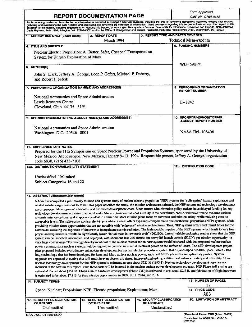
Form Approved
REPORT DOCUMENTATION PAGE OMB No. 0704-0188
Public mpoaing burden for this _ of inlormalion is estimated to average 1 hour per response, iftcludng the time for reviewinginstructions,searchingexisting data sources,galtmdng and mamtainklg tile data needed, and completingand reviewingthe collectionof reformation. Send comments mgan:lingthis burd<mestimateor any other aspect of thiscollection of infocmation,includingsuggeslions Ior reducing this burden, to Wasttingtl_ Headquarters Services,Directoratefor InfonnalionOperations and Reports, 1215 Jeffecse_Davis Highway, Suite 1204, Arlington,VA 222024302, and to the Office of Management and Budget,Paperwork _ Project(0704-0188), Washington, DC 20503.
1. AGENCY USE ONLY (Leave b/ank) 2. REPORT DATE 3. REPORT TYPE AND DATES COVERED
March 1994 Technical Memorandum
4. TITLE AND SUBTITLE S. FUNDING NUMBERS
Nuclear Electric Propulsion: A "Better, Safer, Cheaper" Transportation
System for Human Exploration of Mars
6. AUTHORiS)
John S. Clark, Jeffrey A. George, Leon P. Gefert, Michael P. Doherty,and Robert J. Sefcik
7. PERFORMING ORGANIZATION NAME(S) AND ADDRESSEES)
National Aeronautics and Space AdministrationLewis Research Center
Cleveland, Ohio 44135-3191
g. SPONSORING/MONITORING AGENCY NAME(S) AND ADDRESS(ES)
National Aeronautics and Space Administration
Washington, D.C. 20546-0001
WU-593-71
8. PERFORMING ORGANIZATION
REPORT NUMBER
E-8242
10. SPONSORING/MONITORING
AGENCY REPORT NUMBER
NASA TM- 106406
11. SUPPLEMENTARY NOTES
Prepared for the llth Symposium on Space Nuclear Power and Propulsion Systems, sponsored by the University of
New Mexico, Albuquerque, New Mexico, January 9-13, 1994. Responsible person, Jeffrey A. George, organizationcode 6830, (216) 433-7108.
12L DISTRIBUTION/AVAILABILITY STATEMENT
Unclassified- Unlimited
Subject Categories 16 and 20
12b. DISTRIBUTION CODE
13. ABSTRACT (Maximum 200 words)
NASA has completed a preliminary mission and systems study of nuclear electric propulsion (NEP) systems for "'split-sprint" human exploration and
related robotic cargo missions to Mars. This paper describes the study, the mission architecane selected, the NEP system and technology development
needs, proposed development schedules, and estimated development costs. Since ore'rent administration policy makers have delayed funding for key
technology development activities that could make Mars exploration missions a reality in the near futm-e, NASA will have time to evaluate various
alternate mission options, and it appears prudent to ensure that Mars mission plans focus on astronaut and mission safety, while reducing costs to
acceptable levels. The split-sprint nuclear electric propulsion system offers trip times comparable to nuclear thermal propulsion (NTP) systems, while
providing mission abort opportunities that are not possible with "reference" mission architectures. Thus, NEP systems offer short transit times for the
astronauts, reducing the exposure of the crew to intergalactic cosmic radiation. The high specific impulse of the NEP system, which leads to very low
propellant requirements, results in significandy lower "initial mass in low earth orbit" (IMLEO). Launch vehicle packaging studies show that the NEP
system can be launched, assembled, and deployed, with about one less 240-metric-ton heavy lift launch vehicle (HLLV) per mission opportunity - a
very large cost savings! Technology development cost of the nuclear reactor for an NEP system would be shared with the proposed nuclear surface
power systems, since nuclear systems will be required to provide substautial elecwical power on the surface of Mars. The NEP development project
plan proposed includes evolutionary technology development for nuclear electric propulsion system that expands upon SP-IO0 (Space Power - 100
kwe) technology that has been developed for lunar and Mars surface nuclear power, and small NEP systems for interplanetary probes. System
upgrades are expected to evolve that will result in even shorter trip times, improved payload capabilities, and enhanced safety and reliability. Non-
nuclear technology development for the NEP system is estimated to cost about $721 M (1993 $). Nuclear technology development costs are not
included in the costs in this report, since these costs will be incurred in the nuclear surface power development program. NEP Phase A/B studies are
estimated to cost about $154 M. Flight system hardware development (Phase C/D) is estimated to cost about $2.8 B, and fabrication of flight hardware
is estimated to be about $7.8 B for four mission opporamities in 2009, 2011, 2014, and 2016.
14. SUBJECT TERMS
Space; Nuclear; Propulsion; NEP; Electric propulsion; Exploration; Mars
17. SECURITY CLASSIFICATION
OF REPORT
Unclassified
18. SECURITY CLASSIFICATION
OF THIS PAGE
Unclassified
NSN 75,40-01-280-5500
19. SECURITY CLASSIFICATIONOF ABSTRACT
Unclassified
15. NUMBER OF PAGES
1716. PRICE CODE
A0320. UMITATION OF ABSTRACT
Standard Form 298 (Rev. 2-89)
Prescribed by ANSI Std. Z39-18298-102