NTG Technical Drawings Part 2 Civil CADD Manual ID Version Issued Printed Page NTG Technical...
38
DEPARTMENT OF INFRASTRUCTURE, PLANNING AND LOGISTICS NTG Technical Drawings Part 2 – Civil CADD Manual
Transcript of NTG Technical Drawings Part 2 Civil CADD Manual ID Version Issued Printed Page NTG Technical...

DEPARTMENT OF INFRASTRUCTURE, PLANNING AND LOGISTICS
NTG Technical Drawings Part 2 – Civil CADD Manual

Doc ID Version Issued Printed Page
NTG Technical Drawings Part 2 – Civil CADD Manual 1.7 June 2017 27/07/2017 2 of 38
Approval Sheet
Title
NTG Technical Drawings
Part 2 - Civil CADD Manual
Version Number 1.7
Approved By
Name: Stephen Jackson
Date: 6/06/2017
Engineering and Environment Services
A / Senior Director
Endorsed By
Name: Sam Hatzivalsamis
Date: 6/06/2017
Civil Design
Manager Projects
Prepared By
Name: Bernard O’Donnell
Date: 30/05/2017
Civil Design
Senior Project Manager

Doc ID Version Issued Printed Page
NTG Technical Drawings Part 2 – Civil CADD Manual 1.7 June 2017 27/07/2017 3 of 38
Table of Contents
1 ..... Overview 5
2 ...... Data 6
2.1 CADD Packages .......................................................................................... 6
2.2 Format ......................................................................................................... 6
2.3 Target Formats ............................................................................................ 6
3 ..... General Drawing Standards 7
3.1 Line Attributes .............................................................................................. 7
3.2 Text Attributes ............................................................................................. 8
3.3 Layer Names ............................................................................................... 9
3.3.1 New layers and the Naming of New Layers ....................................... 9
3.4 Coordinate Display .................................................................................... 10
3.5 Font ........................................................................................................... 10
3.6 Reference Files ......................................................................................... 11
3.7 Standardised Drawing Profiles ................................................................... 11
3.8 Drawing Sheet ........................................................................................... 12
3.9 Drawing Title Blocks .................................................................................. 12
3.10 Typical Drawing Sheets and their Descriptions .......................................... 12
3.10.1 Urban Drawing Sets ........................................................................ 12
3.10.2 Rural Drawing Sets ......................................................................... 16

Doc ID Version Issued Printed Page
NTG Technical Drawings Part 2 – Civil CADD Manual 1.7 June 2017 27/07/2017 4 of 38
TABLES
TABLE 1.0 - File formats accepted by NTG CADD applications ....................................................... 6
TABLE 2.0 - Line Colours and Weights (Standard) ........................................................................... 7
TABLE 3.0 - Line Colours and Weights (Additional) .......................................................................... 8
TABLE 4.0 - Text Colours and Weights ............................................................................................. 8
TABLE 5.0 - Coordinate displays ..................................................................................................... 10
TABLE 6.0 - Font displays ................................................................................................................ 11
FIGURES
FIGURE 1 – Cover Sheet Drawing Example Sheet - AutoCAD ....................................................... 18
FIGURE 2 – Typical Cross Sections and Details Drawing Example Sheet - AutoCAD ................... 19
FIGURE 3 – Culvert Drawing Example Sheet - AutoCAD ............................................................... 20
FIGURE 4 – Plan and Longitudinal Drawing Example Sheet - AutoCAD ........................................ 21
FIGURE 5 – Cross Section Drawing Example Sheet - AutoCAD .................................................... 22
FIGURE 6 – Cover Sheet Drawing Example Sheet – Microstation ................................................. 23
FIGURE 7 – Typical Cross Sections and Details Drawing Example Sheet - Microstation .............. 24
FIGURE 8 – Culvert Drawing Example Sheet - Microstation ........................................................... 25
FIGURE 9 – Plan and Longitudinal Drawing Example Sheet - Microstation ................................... 26
FIGURE 10 – Cross Section Drawing Example Sheet - Microstation .............................................. 27
FIGURE 11 – Microstation File Structure Table – Survey Page 1 of 2 ............................................ 28
FIGURE 12 – Microstation File Structure Table – Survey Page 2 of 2 ............................................ 29
FIGURE 13 – AutoCAD File Structure Table – Survey Page 1 of 2 ................................................ 30
FIGURE 14 – AutoCAD File Structure Table – Survey Page 2 of 2 ................................................ 31
FIGURE 15 – Microstation File Structure Table – Civil Page 1 of 2 ................................................ 32
FIGURE 16 – Microstation File Structure Table – Civil Page 2 of 2 ................................................ 33
FIGURE 17 – AutoCAD File Structure Table – Civil Page 1 of 2 ..................................................... 34
FIGURE 18 – AutoCAD File Structure Table – Civil Page 2 of 2 ..................................................... 35
FIGURE 19 - Sign Cells & Traffic Symbols Library .......................................................................... 36

Doc ID Version Issued Printed Page
NTG Technical Drawings Part 2 – Civil CADD Manual 1.7 June 2017 27/07/2017 5 of 38
1 Overview
This Computer Aided Design and Drafting (CADD) Manual has been developed to
document the requirements of the Northern Territory Government (NTG) and to
describe the procedures to be followed in the production of electronic drawings, to
ensure uniformity of both the data being generated using CADD and the data being
supplied to Technical Records from external sources.
This manual is to be read in conjunction with the Department’s “NTG Technical
Drawings Part 1 - Requirements for Technical Record Management” document for
specific reference to document management and transfer.

Doc ID Version Issued Printed Page
NTG Technical Drawings Part 2 – Civil CADD Manual 1.7 June 2017 27/07/2017 6 of 38
2 Data
2.1 CADD Packages
The NTG uses a range of CADD packages. The data is to be supplied in a format
suitable to the receiving CADD package. Currently supported CADD packages are:
AutoCAD 2017, a three-dimensional modelling package used for producing
mechanical, structural, electrical and architectural drawings.
Microstation V8i Edition (08.11.07.443). A three dimensional computer aided
design package, used mainly for civil and hydraulic works.
12d Model Edition (10 and 11). Three-dimensional modelling software used by
Civil Sections.
AutoTURN Version 9.0. Roadway design software tool for analysing and
evaluating vehicle manoeuvres associated with project specific design vehicles
turning paths.
2.2 Format
CADD data is to be supplied in a data format agreed to by the NTG and compatible with
currently used versions of the supported CADD packages listed above and as detailed
in the Department’s “NTG Technical Drawings Part 1 - Requirements for Technical
Record Management” document and included in the AutoCAD Civil and Survey
Drawing Profiles.
2.3 Target Formats
Table showing acceptable data formats for receiving CADD package combinations.
TABLE 1.0 - File formats accepted by NTG CADD applications
File Extensions
Formats accepted by applications
AutoCAD Revit 12d
Model MicroStation AutoTURN Geopak
Dwg ,dxf (Release 12 – 2016) yes yes yes Yes no no
Dwg,dxf ( Post 2016 Release) yes yes yes Yes no no
Rvt (Revit 2015 Release) no yes no No no no
Dgn (Microstation) yes no yes Yes yes yes
tin, dat (Digital Terrain or Surface Model)
File
no yes yes No no yes
4dw (12d Model ) no no yes No no no

Doc ID Version Issued Printed Page
NTG Technical Drawings Part 2 – Civil CADD Manual 1.7 June 2017 27/07/2017 7 of 38
3 General Drawing Standards
The drawings must comply with:
AS 1100.101-1992 and AS 1100.101-1992/Amdt1-1994: Technical drawing –
General principles.
AS 1100.201-1992 and AS 1100.201-1994/Amdt1-1994: Technical drawing –
Mechanical engineering drawing.
AS 1100.301-1985 and AS 1100.301-2008/Amdt1-2011: Architectural drawing.
AS 1100.401-1984 and AS 1100.401-1984/Amdt1-1984: Technical drawing -
Engineering survey and engineering survey design drawing
AS/NZS 1100.501:200: Technical drawing – Structural engineering drawing.
In order to keep the drawing intact with its reference files data, the model space in the
drawing must not be moved to different coordinates or rotated to different angles, and
the scale is to be kept at 1 to 1.
Where this Manual and the Drawing Standards differ, the direction of this manual will
take precedence with consideration of the Drawing Standards’ intent. Where doubt
exists refer concerns to the designated Project Manager.
3.1 Line Attributes
The NTG has adopted seven line thicknesses/weights to be used in the presentation of
drawings. All drawing details are to be represented by using these line weights. On
electronic plans, single vector lines of specified colour are used to represent these line
weights. The correlation between line colour and weight is shown in Table 2.0, Figures
11 to 18, and as incorporated in the Civil and Survey Drawing Profiles. When
transferred to the NTG, no other line colour/weight combination is to be supplied unless
by agreement with the Project Manager/Officer.
TABLE 2.0 - Line Colours and Weights (Standard)
Line Weights*
Microstation AutoCAD
Line Colour Colour Number
Line Colour Colour Number
0.18 mm
green
2 green
3
0.2 mm
- - cyan 4
0.25 mm white or
black/magenta/cyan
0,5,7 magenta/black 6, 7
0.35 mm
yellow
4 yellow 2
0.5 mm
red
3 red 1
0.7 mm
blue
1 blue 5
1.0 mm
orange
6 - -
* Refer to discipline specific guidelines as they may differ slightly.

Doc ID Version Issued Printed Page
NTG Technical Drawings Part 2 – Civil CADD Manual 1.7 June 2017 27/07/2017 8 of 38
Where additional clarity (e.g. presentation drawings) is required, the colours below should be considered for use:
TABLE 3.0 - Line Colours and Weights (Additional)
Line
Weights Colour
Colour Number
Colour
Colour Number
Microstation AutoCAD Microstation AutoCAD
0.25 mm All Others
0.35 mm Brown 70 32 Mustard 68 42
0.5 mm Light
Green 12 60 Pink 10 210
0.13 mm Grey - 253 Grey 9 8
NB. Where lines are required to be shown as background information or reduce density hatching, colour 8 (grey) for AutoCAD (or colour 9 for Microstation) should be used.
AutoCAD users have additional grey scales that can be used. All of the shades of grey having some percentage of screening value assigned to that colour. This would include pen 255, 254, 253, 252, 251, 250, 9 and 8 having screening of 0, 10, 20, 30, 40, 50, 60 and 70 percent to each of the colour.
When plotting an “A1” size sheet at “A3” the line widths should be halved (the reduction factor when reducing “A1” sheets to “A3” size sheets).
3.2 Text Attributes
NTG accepts four text heights to be used in the presentation of drawings. All text on the
drawings is to be represented by using these text heights. The correlation between text
colour, weight and height is as shown in Table 4.0. When transferred to the NTG, no
other text colour / weight / height combination is to be supplied unless written approval
is obtain from the delegated Project Manager.
TABLE 4.0 - Text Colours and Weights
Text Height
Microstation AutoCAD
Text Colour Colour Number Text Colour Colour Number
2.5mm white or
black/magenta/cyan
0 magenta/black 7
3.5mm yellow 4 yellow 2
5.0mm red 3 red 1
7.0mm blue 1 blue 5

Doc ID Version Issued Printed Page
NTG Technical Drawings Part 2 – Civil CADD Manual 1.7 June 2017 27/07/2017 9 of 38
3.3 Layer/Level Names
The intent of the layer/level naming system is to have an intuitive layer/level naming
structure that will allow any item/object to be “turned off” without affecting any other
information on the drawing. Within the Civil and Survey Drawing Profile (refer 3.7
Standard Drawing Profiles) Line styles and their naming convention has been
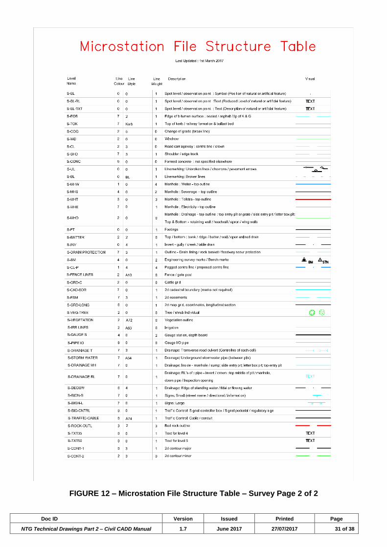
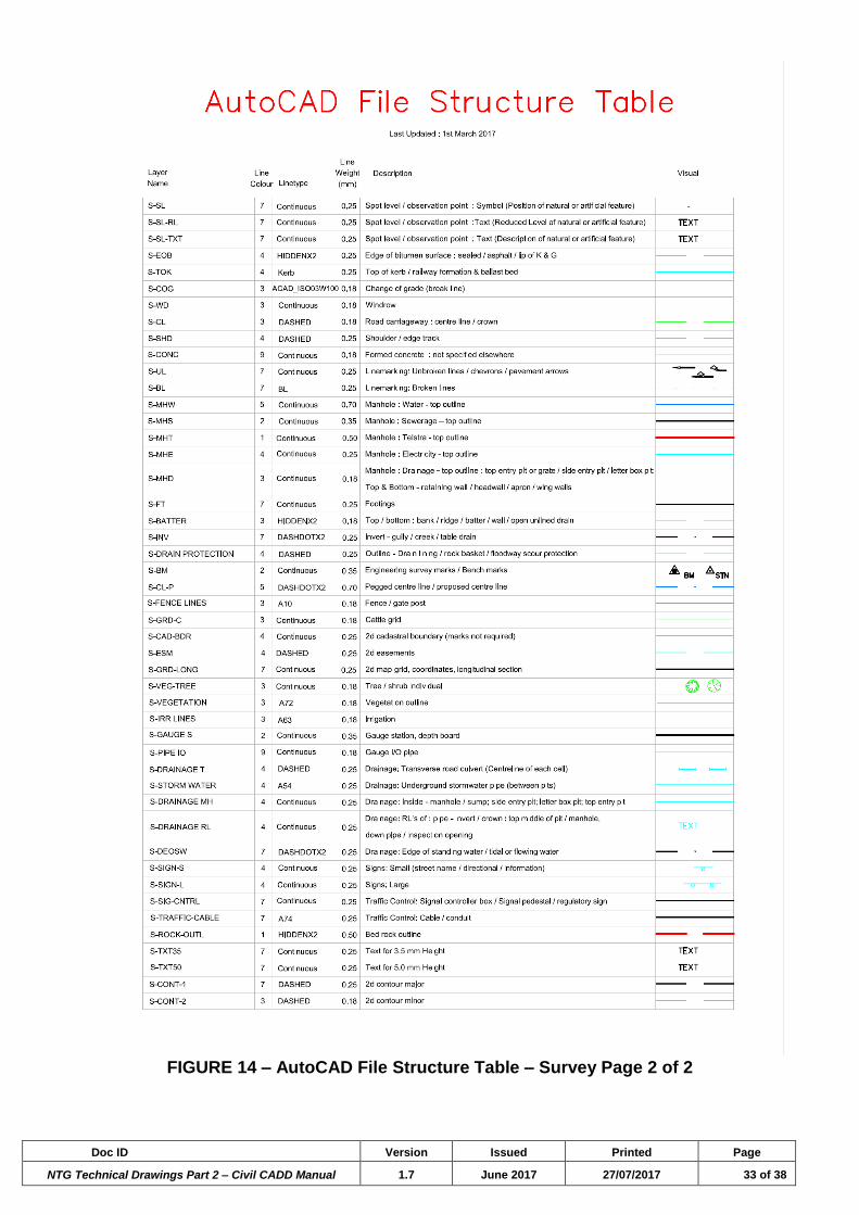
established. These line styles and their attributes are tabled in figures 11 through to 18.
The use of layers (in AutoCAD) and levels (in Microstation) has also been standardized
and is outlined in the file structure tables. As a general rule, a particular element should
be generated on the appropriate layer/level. When deciding to place an element on a
discrete layer/level consideration needs to be given as to whether there is an explicit
need to have the element displayed or frozen, for example, when the file is to be used by
other disciplines, they may need to turn off hatching, thus all hatching should be
generated on the layer “C-HAT”.
3.3.1 New Layers/Levels and the Naming of New Layers/Levels
Layer/level names are subdivided into major and minor groups. If a new layer/level is to
be created, then the layer/level name will need to adopt the following format:
#-**nnn
Where:
“#” is the Discipline Identifier (C = Civil, E = Electrical, M = Mechanical,
P = PAWA Projects, S = Survey).
“-“ is the minus character.
“**” is the sub-types of each of the Discipline Identifiers (e.g. DIM = Dimension,
TXT = Text, HAT = Hatch patterns, DSH = general dashed style lines).
“nnn” is the modifier relating to line thickness at full scale (e.g.
20,25,35,50,70,100). Otherwise leave blank.
Here are some examples: C-TXT20, C-DIM35, M-HAT100 etc…
The operator will be responsible for the consistent use of layer/level names throughout
all of their drawing files, and ensure that the data is on the relevant layer/level.

Doc ID Version Issued Printed Page
NTG Technical Drawings Part 2 – Civil CADD Manual 1.7 June 2017 27/07/2017 10 of 38
3.4 Coordinate Display
TABLE 5.0 - Coordinate displays
Microstation
Master
Units Sub Units Coordinate Readout Examples
Working Units Metre (m) Millimetre (mm) D.DDD 0.123
Angles Degree ( ^ )
Minute ( ‘ )
Second ( “)
D.DDD
Or DD MM SS
45.123^
Or 45^20’05”
Coordinates
When giving coordinates the ‘x’ coordinate shall be the Easting and the ‘y’
coordinate the Northing. When providing an angle direction, zero degrees is
to the East.
AutoCAD
Units Units Format Precision
Length Type Metre (m) Decimal To suit Application
default 3
Angle Type Degree Decimal
Degrees To suit Application
Coordinates
When giving coordinates the ‘x’ coordinate shall be the Easting and the ‘y’
coordinate the Northing. When providing an angle direction, zero degrees is
to the East.
3.5 Font
NTG requires Arial True Type Font to be used in the Title Blocks on NTG Drawing
Sheets. For other presentations and design drawings, the following criteria applies:
The font is vector based for all descriptions within the drawing.
The font is true type format for all text.
General form of characters to be in accordance with AS1100.101:1992 and
ISO3098-1:1997.
Cell size / aspect ratio to be 1.
Characters to be monospaced.
To comply with these requirements it is suggested to use the fonts shown in Table 6.0
for the nominated applications, for all text, unless otherwise specified.
Doc ID Version Issued Printed Page
NTG Technical Drawings Part 2 – Civil CADD Manual 1.7 June 2017 27/07/2017 11 of 38
TABLE 6.0 - Font displays
Application Font
AutoCAD
ISO CP – for Drawing Text (available in the Civil and Survey Drawing Profiles)
Arial – for Title Block Text
MicroStation ISOREC 27 – for Drawing Text
Arial – for Title Block Text
All special fonts used in the production of drawings are to be supplied by the Consultant,
e.g. special fonts used for symbols not available in Arial. Company logos are to be
embedded blocks or images.
3.6 Reference Files
Reference files are design or raster files that can be attached, displayed and plotted. In
the case of reference design files used for construction purposes, they cannot be
modified in any way.
They improve the efficiency of the CADD process by displaying data from different
design files in the active file. When one of the referenced drawings is changed that
change is reflected in every design file that the file has been referenced into.
When drawing data is supplied to the NTG that has attached reference files, the NTG
require that the attached files are merged or bound into the drawing. AutoCAD users
may use eTransmit to include all related dependent files with a zip file or a folder option
in a transmittal package. Otherwise the following rules apply:
• All reference files used must be supplied.
• Files should not be saved with the full file path, as the link to them will not be
resolved by the CADD application,
• If it is not possible to supply the reference files then all the reference files should
be combined into one drawing.
3.7 Standardised Drawing Profiles
There are two standardised civil works drawing profiles that are downloadable from the
Department’s web site.
https://dipl.nt.gov.au/infrastructure/technical-records/manuals-templates.
One is the Civil, and the other is the Survey drawing profile.
The civil and survey drawing profiles both contain prepared drawing sheets, layers, dim
styles, text styles, menus and line styles for consultants to use. This tool is provided to
help retain the NTG’s quality assurance and maintain consistency across all drawings,
irrespective of the author of the drawings.
The Civil Drawing Profile has a drop down list for quick access to the block library of
most of the signs used on Australian roads. Refer to Figure 19 as an example of what is
available.

Doc ID Version Issued Printed Page
NTG Technical Drawings Part 2 – Civil CADD Manual 1.7 June 2017 27/07/2017 12 of 38
3.8 Drawing Sheet
The NTG has its own A1 drawing template. This template is within the new Civil and
survey Drawing Profiles. By using the NTG template and profile setup, plotting sizes can
be changed using the A1 to A3 setting within the plot styles table drop down.
Screening of colours and colour plotting are also available.
3.9 Drawing Title Blocks
NTG title blocks are to be used on all NTG works. Refer to Section 6 of the Department’s
“NTG Technical Drawings Part 1 - Requirements for Technical Record Management”
document.
3.10 Typical Drawing Sheets and their Descriptions
There are typically two types of civil road works drawing sets, the first comprising of
drawings required for the urban environment and the second comprising of drawings
required for the rural environment.
3.10.1 Urban Drawing Sets
Civil urban road works are more complex, require more detail and are
generally broken down into groups. A list of these groups and the
drawings within each group are typical but not limited to what is outlined
below. The total number of drawings, and their groups, will depend on the
existing and or design infrastructure, within the scope of works.
Overall Group includes:
Schedule of Drawings & Locality Plan.
The schedule of project drawings is to be tabled, and, shall include the
project specific drawings by discipline and the standard drawings
relevant to, and associated with the scope of works.
The survey station control points are to be tabled.
The “Basis of Design” elements shall be listed, and include, but not
limited to Design Speed, Speed Environment, Adopted/Applied
Drainage Design, Pavement Design ESAs, Adopted Design Subgrade
Strength, Design Vehicle, Check Vehicle, and, reference the
standards and guidelines used for the design.
The locality plan is to show the location of the site of works.
Typical Cross Sections and Details.
Typical cross sections are to show the typical existing formation,
design formation, design centre line, traffic islands, carriageways and
traffic lanes, shoulder, kerb and gutter, pavement type and thickness,
road surface treatment, typical services location, footpath, property
boundary, verge and road reserve.
Drawing details are to show anything that isn’t already shown in a
standard drawing or in a manufacture’s specification.

Doc ID Version Issued Printed Page
NTG Technical Drawings Part 2 – Civil CADD Manual 1.7 June 2017 27/07/2017 13 of 38
Civil Works
Setout Drawings.
These drawings are to contain all horizontal changes and references,
including Chainages, Coordinates (Easting and Northing), Radii and
Tangent Bearings in a table, and
A plan view with the chainages running from left to right sequentially
and oriented such that they are read from the lower right corner of the
drawing, and, accompanied with a north arrow for orientation.
Plans and Longitudinal Sections.
The plans in these drawings shall show chainages, road centreline
and relevant horizontal alignment information including kerb types and
extents, the design road corridor layout, services including sewer,
water, power and stormwater. Show existing services and any
impacts on those services, and delineate those services that are being
kept and those being removed. Show in the designed layout any
features of significants such as signs and sign descriptions. Do not
show lighting as they are to be shown on separate lighting plans.
The following are to be shown on the longitudinal sections in these
drawings; Longitudinal Design Line, Existing Surface, cross sectional
location of services, extent of the various Typical Cross Section
Types, Vertical Alignment information including grades as a
percentage and Vertical Curve radii and lengths, Datum line,
Earthworks Cut and Fill volumes, Difference between design and
existing surface levels, Design Reduced Levels, Existing Surface
Reduced Levels, Chainages, applied Superelevation and Transition
Lengths.
Cross Section Drawings.
Details to include the design formation with cross falls in percent, the
existing formation, design levels, existing surface levels and offset
distances from the design line. Show any services present at that
particular cross section chainage.
Kerb and Drainage Drawings.
Show in plan views the location of kerbs, stormwater pipes and entry
pits. All drainage lines and pits are to be identified by alpha numeric
sequencing. Noted of the drawings are the type of kerbs, type of pits
and how number of bays within a side entry pit, existing stormwater
lines, existing kerbs, setout points and tables containing the ID,
easting, northing, RL/IL and description.

Doc ID Version Issued Printed Page
NTG Technical Drawings Part 2 – Civil CADD Manual 1.7 June 2017 27/07/2017 14 of 38
The drainage lines, inclusive of the stormwater pipes and pits are also
to be shown in longitudinal sections. The longitudinal sections are to
show the pit identification, Pipe Grades, sizes of pipes, depths to pipe
invert levels from the surface, Invert Levels, Finished Surface Level,
Existing Surface Level, Chainage, the connections from one line to
another, and, the location of other services transversely crossing the
drainage lines.
Pavement Composition Plans.
Show the different pavements, surface types and treatments, and
their locations. Each surface type and treatment is to be delineated as
a different hatching. The hatching shall be listed in a legend with a full
description.
Traffic Control Drawings.
These drawing are to show all of the pavement markings and signs.
Line markings are to be shown with an adequate number of ID and x &
y coordinates for setout purposes. The x and y coordinates are to be
captured in a table on the drawing complete with the ID number at the
start and end of all lines and chevron, tips of turning arrows, the centre
point of any curves, TC and CT points and any curve radii. The type of
line marking is to be show on the plan and is also to be represented in
a Legend within the drawings.
All signs required are to be illustrated, accompanied with their sign
number and their positioning by chainage in accordance with AS1742,
no need for coordinates.
Shared Path / Cycle Paths.
These drawings are likened to a miniature set of project drawings
requiring their own typical cross section and details, Plan and
Longitudinal Sections and Cross Section Drawings.
Doc ID Version Issued Printed Page
NTG Technical Drawings Part 2 – Civil CADD Manual 1.7 June 2017 27/07/2017 15 of 38
Traffic Signals
Traffic Signal Layout Plans.
The traffic signals layout plans are to be consistent with the
requirements of the Traffic Signals Brief.
The drawings shall show the layout of the intersection in a lighter
colour, and include, but not limited to, the signal poles and the pole
number, the signal symbols for each pole and alphabetical numbering,
the Signal Detector Loops and their groups, Conduit, Traffic Signal
Controller, Power connection, Communications Pit, Detector Cable Pit
and Conduit Junction Pit.
The drawings shall include a Lantern Schedule and an appropriate
Legend. The lantern schedule is to show the Type of Signal, Size of
the Signal, Lantern Head, Cowls Opened or Closed and Pole
Location. The legend shall include all symbols as per the Australian
Standards, the Type of Signal Symbols and the corresponding
alphabetical numbering, Pole / Pedestal Symbol, Conduit Junction Pit,
Detector Cable Pit, Traffic Signal Controller, Detector Loops, Conduit
sizes and Signal Group.
Traffic Signal Electrical Works Drawing.
These drawings contain detail in plan view of the electrical layout as
per the Traffic Signals Layout Plan. The purpose of these drawings is
to show the phases of the signals including schematic diagrams for
each signal phase and the electrical tables showing the conflicts,
signal groups, run / phases and detector loops. This drawing is a
standard drawing that is obtainable from NTG Technical Records and
of which requires filling out by a competent operator or traffic engineer
in accordance with the Department’s Traffic Signal Brief.
Doc ID Version Issued Printed Page
NTG Technical Drawings Part 2 – Civil CADD Manual 1.7 June 2017 27/07/2017 16 of 38
Landscaping Drawings
Cover Page
The cover page shows the Site Location and Project Drawing
Schedule.
Landscape Works Plans.
The Landscape Works Plans show the positioning of flora,
landscaping and sculptures within the road reserve. The plan is to
include a Legend that explains the symbols represented within the
drawings.
Schedule of Landscaping Works.
The schedule is to contain Shrub Planting Schedule, Tree Planting
Schedule, Topsoil Schedule and Fertilizer Schedule.
Landscaping Details.
Contains drawing details that are not captured on the other drawings
in the set or in the standard drawings.
Technical Notes.
This drawing typically contains, but is not limited to, notes on Soils,
Grassing, Planting, Irrigation and Establishment.

Doc ID Version Issued Printed Page
NTG Technical Drawings Part 2 – Civil CADD Manual 1.7 June 2017 27/07/2017 17 of 38
Street Lighting
Locality Plan, Legend & Notes.
This Drawing shows the location of the works, the Design criteria
adopted, a Legend containing symbols used throughout the drawing
and their description, and, General Notes, Works by Power and Water
Notes and Works by Developers Contractors Notes.
Street Lighting Reticulation.
These drawings are a plan view layout showing the existing lighting,
new lighting, and any removal and/or replacement of any lighting. This
drawing also shows the electrical reticulation, supply points, pits and
specific notes.
Street Lighting Pole / Luminaire Schedule.
The drawing contains a tabled schedule which includes, The Pole
Number, Street Light Number, Size, Type, Outreach Type, Luminaire
Type and any remark required about the works required.
Street Light Single Line Diagram.
This drawing is a schematic diagram of the electrical lines with lengths
between poles, phases between poles Light number and cable pits

Doc ID Version Issued Printed Page
NTG Technical Drawings Part 2 – Civil CADD Manual 1.7 June 2017 27/07/2017 18 of 38
3.10.2 Rural Drawing Sets
Within a set of rural civil road works drawings there are 5 typical types of
drawings. Rural road drawings are not limited to these typical five
drawings, however, all rural road drawings need to contain at least the
five drawing types mentioned below (Note culvert drawings being the
exception, if no culverts exist). There may be a need for other drawing
types to be included to cover such works as detours and rehabilitation
works etc. Each of the five required drawings is described below and on
Figures 1 to 10.
Overall Group includes:
Cover sheet Schedule of Drawings & Locality Plan.
The schedule of project drawings is to be tabled, and, shall include the
project specific drawings and the standard drawings relevant to, and
associated with the scope of works.
The survey station control points are to be tabled.
The “Basis of Design” elements shall be listed, and include, but not
limited to Design Speed, Speed Environment, Adopted/Applied
Drainage Design, Pavement Design ESAs, Adopted Design Subgrade
Strength, Design Vehicle, and, reference the standards and
guidelines used for the design.
The locality plan is to show the location of the site of works.
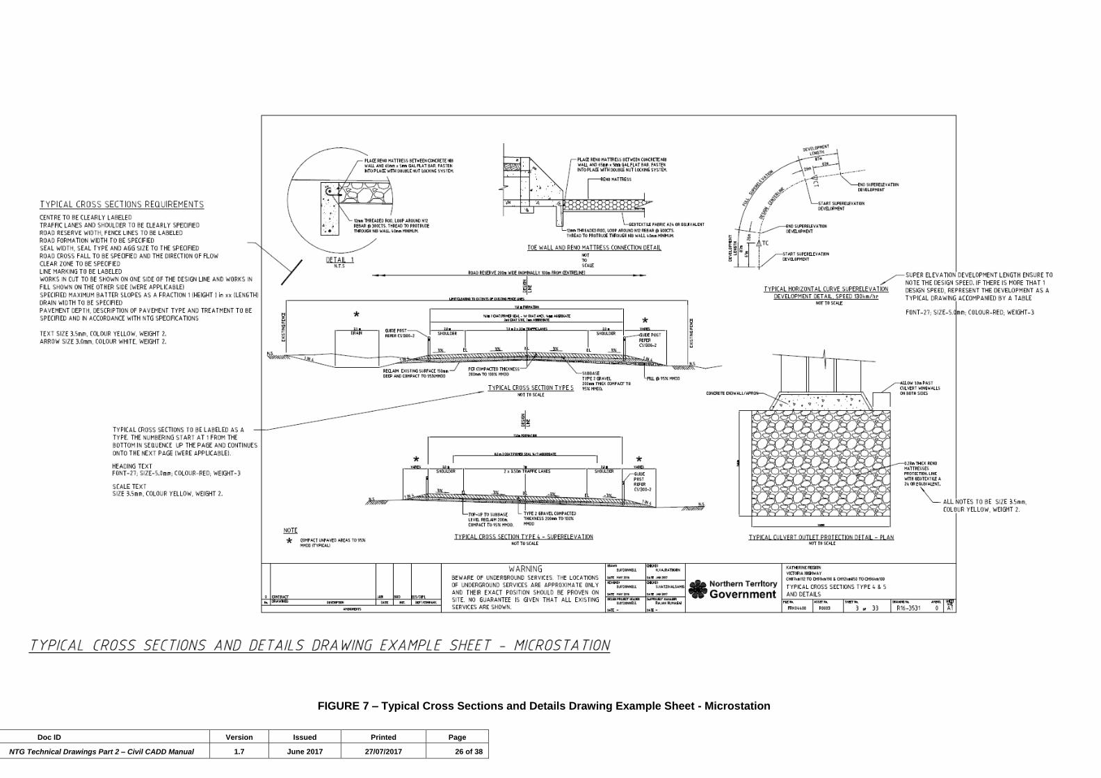
Typical Cross Sections and Details.
Typical cross sections are to show the typical existing formation,
design formation, design centre line, carriageways and traffic lanes,
shoulders, kerb and gutter, pavement type and thickness, road
surface treatment, typical services location, property/road reserve
boundaries, drainage structures, batters slopes, cut slopes.
Drawing details are to show anything that isn’t already shown in a
standard drawing or in a manufacture’s specification.
Culvert Details.
As a minimum, cross sections of culverts are to be provided.
The cross sections shall include the following information, and as
typically shown on Figures 3 and 8; Culvert Number, Chainage
location of the culvert, number of cells, number of link slabs, size and
type of culvert, overall length of culvert, skew angle, Inlet offset
distance from road Design Line or Centreline and invert level, Outlet
offset distance from road Design Line or Centreline and invert level,
inlet and outlet protection.
The clear zone is to be shown to ensure the culvert headwalls are
outsize this zone along with the direction of the flow of water.
Provide any necessary inlet and outlet earthworks treatments and
protection works.
Show any difficult skew angles across the road by the use of a plan
view within the culvert detail drawings.

Doc ID Version Issued Printed Page
NTG Technical Drawings Part 2 – Civil CADD Manual 1.7 June 2017 27/07/2017 19 of 38
Plan and Longitudinal Section Drawings.
The plans in these drawings shall show chainages at one hundred
metre intervals, road centreline and horizontal alignment information
including Bearings, curve data such as the tangent Deflection Angle,
Radius, Arc Length, Tangent Length and Secant Length, the design
road corridor layout, new Traffic Lanes, Floodways, Survey Markers,
Existing Contours, Lot Numbers, property boundaries and property
accesses, and a North Arrow. The plans should also show the start
and end of works and the horizontal location of offlet drains. Show
services including Telecommunications, Power, NBN sewer, water,
power and stormwater, and any impacts on those services.
Delineate those services that are being kept and those being
removed. Show any features of significants such as signs and sign
descriptions.
The following are to be shown on the longitudinal sections in these
drawings; Longitudinal Design Line, Existing Surface, cross sectional
location of services, Cross sectional location of culverts and culvert
details such as; Culvert Number, Chainage location of the culvert,
number of cells, number of link slabs, size and type of culvert, overall
length of culvert, skew angle, Inlet offset distance from road Design
Line or Centreline and invert level, Outlet offset distance from road
Design Line or Centreline and invert level, inlet and outlet protection,
catchment area and design discharge. Show the extent of the
various Typical Cross Section Types, Vertical Alignment information
including grades as a percentage and Vertical Curves radii and
lengths, Datum line, Earthworks Cut and Fill volumes, Difference
between design and existing surface levels, Design Reduced Levels,
Existing Surface Reduced Levels, Chainages at twenty five metre
intervals, Superelevation and Transition Lengths and Traffic Control
Devices which should include line marking, culvert locations and
signs. Signs are to be represented by illustrated images
accompanied with their sign number as per AS 1742. Their
positioning is to be described by a chainage and location Left or Right
of the Design Line/Centreline of the road.
Cross Sections.
Details to include the design formation with cross falls in percent, the
existing formation, design levels, existing surface levels and offset
distances from the design line. Show any services present at that
particular cross section chainage.
Intersection Drawings
The intersection drawings shall provide sufficient detail to construct
the intersection and should include; layout plans with coordinates,
grading plans and pavement marking plans and details.

Doc ID Version Issued Printed Page
NTG Technical Drawings Part 2 – Civil CADD Manual 1.7 June 2017 27/07/2017 20 of 38
FIGURE 1 – Cover Sheet Drawing Example Sheet - AutoCAD

Doc ID Version Issued Printed Page
NTG Technical Drawings Part 2 – Civil CADD Manual 1.7 June 2017 27/07/2017 21 of 38
FIGURE 2 – Typical Cross Sections and Details Drawing Example Sheet - AutoCAD

Doc ID Version Issued Printed Page
NTG Technical Drawings Part 2 – Civil CADD Manual 1.7 June 2017 27/07/2017 22 of 38
FIGURE 3 – Culvert Drawing Example Sheet - AutoCAD

Doc ID Version Issued Printed Page
NTG Technical Drawings Part 2 – Civil CADD Manual 1.7 June 2017 27/07/2017 23 of 38
FIGURE 4 – Plan and Longitudinal Drawing Example Sheet - AutoCAD

Doc ID Version Issued Printed Page
NTG Technical Drawings Part 2 – Civil CADD Manual 1.7 June 2017 27/07/2017 24 of 38
FIGURE 5 – Cross Section Drawing Example Sheet - AutoCAD

Doc ID Version Issued Printed Page
NTG Technical Drawings Part 2 – Civil CADD Manual 1.7 June 2017 27/07/2017 25 of 38
FIGURE 6 – Cover Sheet Drawing Example Sheet – Microstation
Doc ID Version Issued Printed Page
NTG Technical Drawings Part 2 – Civil CADD Manual 1.7 June 2017 27/07/2017 26 of 38
FIGURE 7 – Typical Cross Sections and Details Drawing Example Sheet - Microstation

Doc ID Version Issued Printed Page
NTG Technical Drawings Part 2 – Civil CADD Manual 1.7 June 2017 27/07/2017 27 of 38
FIGURE 8 – Culvert Drawing Example Sheet - Microstation

Doc ID Version Issued Printed Page
NTG Technical Drawings Part 2 – Civil CADD Manual 1.7 June 2017 27/07/2017 28 of 38
FIGURE 9 – Plan and Longitudinal Drawing Example Sheet - Microstation

Doc ID Version Issued Printed Page
NTG Technical Drawings Part 2 – Civil CADD Manual 1.7 June 2017 27/07/2017 29 of 38
FIGURE 10 – Cross Section Drawing Example Sheet - Microstation

Doc ID Version Issued Printed Page
NTG Technical Drawings Part 2 – Civil CADD Manual 1.7 June 2017 27/07/2017 30 of 38
FIGURE 11 – Microstation File Structure Table – Survey Page 1 of 2
Doc ID Version Issued Printed Page
NTG Technical Drawings Part 2 – Civil CADD Manual 1.7 June 2017 27/07/2017 31 of 38
FIGURE 12 – Microstation File Structure Table – Survey Page 2 of 2

Doc ID Version Issued Printed Page
NTG Technical Drawings Part 2 – Civil CADD Manual 1.7 June 2017 27/07/2017 32 of 38
FIGURE 13 – AutoCAD File Structure Table – Survey Page 1 of 2
Doc ID Version Issued Printed Page
NTG Technical Drawings Part 2 – Civil CADD Manual 1.7 June 2017 27/07/2017 33 of 38
FIGURE 14 – AutoCAD File Structure Table – Survey Page 2 of 2

Doc ID Version Issued Printed Page
NTG Technical Drawings Part 2 – Civil CADD Manual 1.7 June 2017 27/07/2017 34 of 38
FIGURE 15 – Microstation File Structure Table – Civil Page 1 of 2

Doc ID Version Issued Printed Page
NTG Technical Drawings Part 2 – Civil CADD Manual 1.7 June 2017 27/07/2017 35 of 38
FIGURE 16 – Microstation File Structure Table – Civil Page 2 of 2

Doc ID Version Issued Printed Page
NTG Technical Drawings Part 2 – Civil CADD Manual 1.7 June 2017 27/07/2017 36 of 38
FIGURE 17 – AutoCAD File Structure Table – Civil Page 1 of 2

Doc ID Version Issued Printed Page
NTG Technical Drawings Part 2 – Civil CADD Manual 1.7 June 2017 27/07/2017 37 of 38
FIGURE 18 – AutoCAD File Structure Table – Civil Page 2 of 2

Doc ID Version Issued Printed Page
NTG Technical Drawings Part 2 – Civil CADD Manual 1.7 June 2017 27/07/2017 38 of 38
FIGURE 19 - Sign Cells & Traffic Symbols Library