NRC Exam Site-Specific SRO Written Examination
149
NRC Exam Site-Specific SRO Written Examination Applicant Information Name: Date: June 28th, 2013 Facility/Unit: Browns Ferry Region: I II III IV Reactor Type: W CE 8W GE Start Time: Finish Time: Instructions Use the answer sheets provided to document your answers. Staple this cover sheet on top of the answer sheets. To pass the examination you must achieve a final grade of at least 80.00 percent overall, with 70.00 percent or better on the SRO-only items if given in conjunction with the RO exam; SRO-only exams given alone require a final grade of 80.00 percent to pass. You have 8 hours to complete the combined examination, and 3 hours if you are only taking the SRO portion. Applicant Certification All work done on this examination is my own. I have neither given nor received aid. Applicant’s Signature Results RO/SRO-Only/Total Examination Values 75 / 25 / 100 Points Applicant’s Scores / / Points Applicant’s Grade / / Percent
Transcript of NRC Exam Site-Specific SRO Written Examination

NRC Exam
Site-Specific SRO Written Examination
Applicant Information
Name:
Date: June 28th, 2013 Facility/Unit: Browns Ferry
Region: I II III IV Reactor Type: W CE 8W GE
Start Time: Finish Time:
Instructions
Use the answer sheets provided to document your answers. Staple this cover sheeton top of the answer sheets. To pass the examination you must achieve a final grade of at least80.00 percent overall, with 70.00 percent or better on the SRO-only items if given in conjunctionwith the RO exam; SRO-only exams given alone require a final grade of 80.00 percent to pass. Youhave 8 hours to complete the combined examination, and 3 hours if you are only taking the SROportion.
Applicant Certification
All work done on this examination is my own. I have neither given nor received aid.
Applicant’s Signature
Results
RO/SRO-Only/Total Examination Values 75 / 25 / 100 Points
Applicant’s Scores
______
/
_____
/
_____
Points
Applicant’s Grade
______
/
_____
/
_____
Percent
SzF—
a)U
CDCD
QU
O0<
CD0
UU
000<
CDU
<C
D<
0<
<C
D
U)
(N0
c)U
)—
c)(N
CDQ
(N(N
(N(N
(N(N
(NN
j—
(N
<<
(NC
<<
<<
CN(N
<<
<000<
<<
LU000
NC
’)0)
c’)N
-0
0N
-0)
0—
00
0(N
C’)
00
C’
CC’J
(NCN0
0
gg
(N
CN(N
(N
C0CD
N-
CD0)
0CN
C’)
U)
CDN
-C
D0)
0—
(NC
’)U
)CD
N-
CD0)
0
0N
-N
-N
-N
-CD
CD
COCD
CDCD
CDCD
CDCD
0)
0)
0)
0)
0
0
C)
UU
0CD
<C
D<
0<
U0
CD<
U0
UU
UU
<<
<<
CD
<
C’)
—U
)—
(N0
(N—
C’)
CC)0
00
Q0
-—
OC
Q—
C’)
0U
)—
(NCD
—U
)ci
U)
(NC
’)C
’)—
N-
—CD
U)
U)
0)
C’)
sa<
<<
0<
C’
CC
’)—
(NC
’)—
00
0(N
CD0
00
0—
00
0C
’)CN
C(N
(NC
’)C
’)0
(N0
00
00
00
00
00
0(N
(N(N
(N(N
CN(N
?C
00000000000
(00
00
—C’)
C’)
N-
N-
CD0)
0)
(N(N
(N(N
(N(N
(N(N
(N(N
(N(N
(N
C0—
(NC
’)U
)C
DN
-CD
0)
0—
(NC
’)U
)CD
N-
CD0)
0—
(NC’)
U)
C)U
)U
)U
)U
)U
)If)
U)
U)
U)
CDCD
CDCD
CDCD
CDCD
CDCD
N-
N-
N-
N-
N-
N
0
C)
0U
CDU
<C
DCD
<0
00
CDU
<U
<C
DCD
UU
COCD
<<
0
CDN
-C
’)—
——
C’)
(N(N
CD—
CD(N
C’)
N-
—(N
N-
——
..—
ooooQ
oO
.ooooooQ
oooo-oo
—(N
-—
c’(N
(N—
LI)(N
-CD
U)
—(N
U)
C’)—
CD
<<
<<
<<
<<
-0
0—
00
0CC’
-U
)0
00
(N(N
(N(N
0—
—(N
00
C’)CD
00
00
00
00
00
00
00
00
00
00
00
0C
’C
’0
00
00
00
00
00
00
00
00
00
00
00
00
C’)U
)0
0)
——
(NU
)U
)U
)N
-N
-CD
C’)
C’)
0)
0)
—(N
(N(N
C’)
C’)
00
CD0
——
——
——
——
CN(N
C’)
U)
CDCD
CDCD
CDCD
(N(N
(N(N
(N(N
(N(N
(N(N
(N(N
(N(N
(N(N
(N(N
(N(N
(N(N
C0CD
N-
CD0)
0—
(NC
’)U
)CD
N-
CD0)
0—
(NC
’)U
)C
DN
-CD
0)
0CI)
(N(N
(N(N
C’)
C’)
C’)
C’)
C’)
C’)
C’)
C’)
C’)
C’)
‘Cl‘1
U)
D0
‘1)
<U
CDU
<0
U<
UU
000
CD<
00
UCD
0CD
U00
CD
C’)
(N—
—(N
(N(N
N-
CD—
-—
C’)
C’)(N
——
(NC
’)—
.C
D0
00
00
C20
C’
00
00
00
00
00
00
00
o
<<
<ci
<c.
<<
<<
<<
<<
<<
0<
0<
<0
UJLU
LULU
LULU
LU<
<<
<<
Ow
—C
’)U
)CD
CD—
C’)
U)
CDCD
0—
N-
CD0
0CD
U)
0(N
00
00
0-
——
(N(N
(N(N
(N(N
C’)
C’)
C’)
C’)
00
0—
—(N
C’)
00
00
00
00
00
00
00
00
00
00
00
0U
)U
)U
)U
)U
)If)
U)
U)
U)
U)
U)
U)
U)
LC)U
)U
)U
)CC)
00
CC)U
)U
)U
)U
)0)
0)
0)
0)
0)
0)
0)
0)
0)
0)
0)
0)
0)
0)
0)
0)
00
0)
0)
0)
0)
0)
(N(N
(N(N
(N(N
(N(N
(N(N
(N(N
(N(N
(N(N
(N(N
CDN
-(N
(N(N
(N(N
Cø4
—(N
C’)U
)CD
N-
CD0)

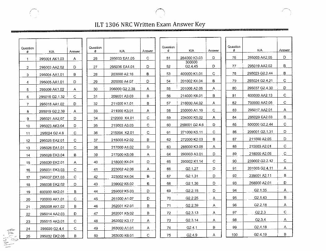
QUESTION 76
At 0900 on April 27th offsite power was lost resulting in the following conditions:
• All 500 KV lines are DE-ENERGIZED
• Athens 16 1KV line is DE-ENERGIZED
• Trinity 161KV line is ENERGIZED
• B and D Emergency Diesel Generators failed to start and can NOT be manually started
At 1000, power has been restored to the Browns Ferry transmission yard via 500KV lines(Limestone and Union).
Which ONE of the following is the LATEST date & time Units I and 2 are required to be inMode 4 in accordance with Technical Specification 3.8.1, AC Sources- Operating?
[REFERENCE PROVIDEDI
• thA. April27 at 2200
B. April 27th at 2300
C. April 28th at 2200
D April 28th at 2300

QUESTION 77
Given the following conditions:
• Unit 3 is operating at 40% power when a loss of drywell control air (DWCA) occurs
• DRYWELL CONTROL AIR PRESS LOW (Panel 9-3E, Window 35) is in Alarm
• MAIN STEAM RELIEF VLV ACCUM PRESS LOW (Panel 9-3D, Window 18) is inAlarm
• DWCA has been cross tied to the Containment Atmospheric Dilution (CAD) System inaccordance with 3-AOI-32A- 1, Loss of Drywell Control Air
Which ONE of the following completes both statements below?
In accordance with the Tech Spec Bases for SR 3.5.1.3, the minimum required pneumaticpressure for the ADS valves to remain operable is j1)_ psig.
The CAD subsystem _(2)_ required to be declared inoperable when crosstied with the DWCASystem.
A. (1)81(2) is
B. (1)81(2) is NOT
C. (1) 87(2) is
D (1)87(2) is NOT

QUESTION 78
Given the following conditions:
• Unit 2 is in a Refueling Outage
• Movement of irradiated fuel is in progress
• Refueling personnel report that a grapple failure has caused a fuel bundle to drop,resulting in the following alarms/indications:
• FUEL POOL FLOOR AREA RADIATION HIGH, (2-9-3A, Window 1)
• 2-RlvI-90-1A, Fuel Pool Area Radiation Monitor is reading 1000 mremlhr
Which one of the following completes the statements below?
Based on the above conditions, the required immediate actions in accordance with 2-AOI-79- 1,Fuel Damage During Refueling, for the SRO is to direct evacuation of non essential personnelfrom the (1).
In accordance with EPIP-l, Emergency Plan Implementing Procedure, the HIGHEST requiredemergency action level classification for these conditions is a (an) _(2)_.
[REFERENCE PROVIDEDj
A. (1) Refuel Floor ONLY(2) Unusual Event
B. (1) Refuel Floor ONLY(2) Alert
C. (1) Drywell AND Refuel Floor(2) Unusual Event
D. (1) Drywell AND Refuel Floor(2) Alert

QUESTION 79
Which ONE of the following completes both statements below?
In accordance with EOI-2, Step PC/P-13, (1) is required to be implemented to controlsuppression chamber pressure less than 55 psig.
In accordance with EPIP-l, Emergency Classification Technical Basis, Section 2.1-G (generalEmergency: Primary containment pressure at 55 psig), at this point, _(2) is (are) potentiallythreatened due to direction in the EOIs to Spray Primary Containment.
A. (1) Appendix 12, Primary Containment Venting(2) fuel cladding integrity
B. (1) Appendix 12, Primary Containment Venting(2) offsite release limits
C. (1) Appendix 13, Emergency Venting Primary Containment(2) fuel cladding integrity
D. (1) Appendix 13, Emergency Venting Primary Containment(2) offsite release limits

QUESTION 80
Given the following conditions:
• Unit 2 was operating at 100% power
• At time 0805 a scram occurred due to a loss of both RPS Bus A and RPS Bus B
• NO control rods initially inserted
• Following the manual scram and ART, several rods failed to fully insert
At 0815, the following conditions exist:
• Reactor power is UNKNOWN
• Reactor pressure is being maintained 800 to 1000 psig with two (2) SRVs OPEN and athird being manually cycled
• Reactor water level is (-)75 inches and steady, being maintained using HPCI
• Suppression pool temperature is 136°F and rising
At 0817, the Shift Manager, as the Site Emergency Director, made an Emergency Plan eventdeclaration in accordance with EPIP-1, EMERGENCY CLASSIFICATION PROCEDURE
Which ONE of the following completes the statement below?
At 0817, the highest required classification is (l)_ and the State of Alabama is required to benotified no later than (2).
(REFERENCE PROVIDEDI
A. (1) General Emergency(2) 0832
B. (1) General Emergency(2) 0835
C. (1) Site Area Emergency(2) 0835
D. (1) Site Area Emergency(2) 0832

QUESTION 81
Given the following conditions:
• All three units are operating at 100% power
• A fire is reported in the 4KV Shutdown Board “C”
• RHR Pump 2B automatically started and then tripped with no operator action
Note:
• l(3)-AOI-lOO-l, Manual Scram
• 0-SSI-9, Unit 2 Reactor Building Fire 4KV Electrical Board Room 2A
Which ONE of the following completes the statements below?
The Shift Manager has entered the SSIs (1 )_, and _(2)_.
A. (1) solely based on the location of the fire(2) all three Units will implement 0-SSI-9
B. (1) due to RHR Pump 2B starting and tripping(2) Units 1 and 3 will implement 1(3)-AOI-lOO-1, and Unit 2 will implement 0-SSI-9
C. (1) due to RHR Pump 2B starting and tripping(2) all three Units will implement 0-SSI-9
D. (1) solely based on the location of the fire(2) Units 1 and 3 will implement 1(3)-AOI-l00-l, and Unit 2 will implement 0-SSI-9

QUESTION 82
Given the following conditions:
• Unit 1 is at 90% power
• Unit 2 is in MODE 5 performing a refueling outage
• Unit 3 is at 100% power
• Severe weather in the area causes grid instabilities
The following conditions exist on Unit 1:
• Incoming Mvars are 150 MVAR
• Grid voltage is 505 kV on the 500kV bus
• Grid voltage is 161kV on the 161kV bus
• Grid frequency is fluctuating from 59.97Hz to 60.03Hz
The grid conditions are RED for the 500kV system and YELLOW for the 161kV system.
Which ONE of the following completes the statements below?
The required action per 0-AOI-57-1E, Grid Instability, is to (1).
In accordance with TRO-TO-SOP-30.128, Browns Ferry Nuclear Plant (BFN) Grid OperatingGuide, the 161KV circuits _(2)_.
A. (1) RAISE reactive load to restore system voltage(2) must be declared inoperable
B. (1) RAISE turbine load to restore system frequency(2) remain operable
C. (1) RAISE reactive load to restore system voltage(2) remain operable
D. (1) RAISE turbine load to restore system frequency(2) must be declared inoperable

QUESTION 83
Given the following conditions:
• Unit 2 was operating at 90%
• An unisolable Main Steam Line break in the Steam Tunnel occurred
• A manual reactor scram was inserted
At time T0, the following conditions exist:
o Stack Noble gas (WRGERMS) release rate is 6.1X 10¹⁰ iiCi/sec
• Actual Site Boundary Dose rate is 950 mRlhr gamma
• The projected Iodine-i 31 Site Boundary measurement is 3.8 X 1 tCi/cm3
Which ONE of the following completes the statements below?
At time T=0, WRGERMS data (l)_ be used to make an emergency declaration.
The highest required emergency classification for this event is _(2)_.
[REFERENCE PROVIDEDj
A. (1) should NOT(2) Site Area Emergency
B. (l)shouldNOT(2) General Emergency
C. (1) should(2) Site Area Emergency
D. (1) should(2) General Emergency

QUESTION 84
Unit 2 was operating at 100% power when a LOCA occurred.Current conditions are as follows:
• RPV water level is (-) 135 inches and steady
• RPV pressure is 275 psig and steady
• Core Spray Loop I is injecting at 7000 gpm, and is the ONLY makeup source
• Drywell pressure is 32 psig
• Suppression Chamber Pressure is 30 psig
• Suppression Pool Water level is 19.5 feet and slowly rising
Based on these conditions, which ONE of the following procedures is required to be entered bythe Unit Supervisor?
A. 2-EOI Appendix 12, Primary Contaimrient Venting
B. EOI C-2, RPV-Emergency Depressurization
C. 2-EO1 Appendix 13, Emergency Venting Primary Containment
D. EOI C-i, Alternate Level Control

QUESTION 85
Given the following conditions:
• A loss of coolant accident (LOCA) has occurred on Unit 1• Suppression Pool level is 16 feet• H2/02 concentrations are as indicated below:
Which ONE of the following completes the statements below?
In accordance with 1 -EOI-Appendix- 19, H2/02 Analyzer Operation, readings from 1 -XR-76- 110H2/02Concentration Recorder (Panel 1-9-54) or from 1-MON-76-1 10, H2/O2Analyzer(Panel 1-9-55) (1).
Based on the current H2/O2readings and in accordance with 1 -EOI-2, PC/H leg, enter_(2)_.
A. (1) are valid as soon as the analyzer is placed in service(2) 1-EOI-Appendix l4A, N2 MAKEUP TO PRIMARY CONTAINMENT
B. (1) are valid as soon as the analyzer is placed in service(2) 1-EOI-Appendix 14B, CAD OPERATION
C. (1) are NOT valid until ten minutes after the analyzer is placed in service(2) 1-EOI Appendix 14A, N2 MAKEUP TO PRIMARY CONTAINMENT
D. (1) are NOT valid until ten minutes after the analyzer is placed in service(2) 1—EOI-Appendix 14B, CAD OPERATION

QUESTION 86
Given the following conditions:
• Unit 2 is operating at 100% Reactor power• Core Spray Loop II has been inoperable since June 15 at 0800
The following Core Spray discharge pipe pressures were reported on June 18 at 0830:
• 2-PI-75-20, CS Loop I Discharge Pressure, 43 psig• 2-PI-75-48, CS Loop II Discharge Pressure, 0 psig
Assuming no further operator action, which ONE of the following identifies the EARLIEST timethat Unit 2 is required to be in Mode 3, in accordance with Tech Specs?
IREFERENCE PROVIDED]
A. June 18 at2130
B. June 18 at2230
C. June22 at 0800
D. June 22 at2000

QUESTION 87
Given the following conditions:
• At 0900 on March 26th Unit 1 scrammed from rated conditions and all rods filly inserted
At 1300:
• RPV Pressure is 500 psig
• Annunciator 9-5B window #13, SLC TEMP ABNORMAL alarms
• The AUO reports that local tank temperature is 530 F and the breakers for the heaters aretripped
• SLC storage tank boron concentration is 12.0%
• The SLC storage tank temperature continues to drop while troubleshooting the trippedbreakers
Which ONE of the following completes the statements below?
At _(1)_ reactor coolant temperature must be less than 212 degrees.
In accordance with Tech Spec Bases 3.1.7, the reason why SLC is required to remain operable inMode 3 is to ensure (2).
[REFERENCE PROVIDEDI
A. (1) 2100 on March 27th(2) offsite doses remain within 1OCFR5O.67 limits following a LOCA
B. (1) 0900 on March 28th(2) shutdown capability exists for the subsequent plant cooldown
C. (l)2l00onMarch27th(2) shutdown capability exists for the subsequent plant cooldown
D. (1) 0900 on March 28th(2) offsite doses remain within 1OCFR5O.67 limits following a LOCA

QUESTION 88
Given the following conditions:
• Unit 1 is in MODE 2 withdrawing control rods for a startup
• IRM D has failed and has been bypassed on Panel 9-5
• All IRM DOWNSCALE alarms have cleared on the operable IRMs
• All IRMs are on range 1
• SRMs are inserted and indicate between 9 x iO cps and 5 x iO cps and are trendinghigher
Subsequently:
• IRM H fails downscale due to a degraded power supply
Which ONE of the following completes the statements below?
The shortest required completion time for a Tech Spec or Technical Requirements Manual, LCORequired Action is _(l)_ hour(s).
Source Range Monitors (SRMs) _(2)_ be withdrawn at this time.
IREFERENCE PROVIDEDj
A. (l)one(2) can NOT
B. (1)one(2) can
C. (l)twelve(2) can NOT
D. (1) twelve(2) can

QUESTION 89
Given the following conditions:
• Unit 3 is operating at 100% power• A loss of 25OVDC RMOV Board 3B occurs
Which ONE of the following identifies the required action statement(s), if any, in accordancewith Technical Specification 3.5.1, ECCS - Operating?
IREFERENCE PROVIDED]
A. Action statements G. 1 and G.2 are required to be entered
B. Action statement E. 1 is required to be entered
C. No action statement in LCO 3.5.1 is required to be entered because LCO 3.0.6 applies
D. Action statement H. 1 is required to be entered

QUESTION 90
Which ONE of the following completes the statements below in accordance with 2-SR-3.4.3.2,Main Steam Relief Valves Manual Cycle Test, acceptance criteria?
Each relief valve shall be manually opened and confirmed OPEN by acoustic monitors_(1)_thermocouples.
The green CLOSED valve indicating light must be confirmed by no acoustic monitor response_(2)_ no steam flow indicated on thermocouples downstream of each relief valve.
A. (1)OR(2) AND
B. (1)AND(2) AND
C. (l)OR(2) OR
D. (1)AND(2) OR

QUESTION 91
Unit 2 has entered 2-AOI-85-4, Loss of RPIS due problems with control rod 10-27 positionindication.
Which ONE of the following completes the statement below?
In accordance with TRM TR 3.3.5, Surveillance Instrumentation, the (1) and_(2) are considered redundant to each other for the parameter of control rod motion.
A. (1) control rod position indicators(2) neutron monitoring instruments
B. (1) control rod position indicators(2) rod drift alarm feature
C. (1) rod drift alarm feature(2) neutron monitoring instruments
D. (1) RPIS iNOPERABLE annunciator (Panel 2-9-5A Window 35)(2) rod drift alarm feature

QUESTION 92
Unit 3 is operating at 100% power when the following occurs:
• Main steam line flow increases rapidly• All Main Steam Line Isolation Valves close, except MSIV LINE A INBOARD,
3-FCV-1-14A, which indicates intermediate.• Main Steam Line Leak Detection High (Panel 9-3D-Window 24) is in alarm and
TIS- 1 -60A reached 240° F and is slowly lowering
Which ONE of the following completes the statements below?
In accordance with the bases for Tech Spec 3.6.1.3, PCIVs, the reason why an additional 4 hoursis allowed in the required completion time for Condition A (due to an inoperable MSIV) is to_(1).
The TSC is _(2)_ to be staffed.
[REFERENCE PROVIDEDI
A. (1) restore the MSIV to Operable before having to reduce power orshutdown the unit
(2) required
B. (1) restore the MSIV to Operable before having to reduce power orshutdown the unit
(2) NOT required
C. (1) implement administrative controls for the Operable in-series valve(2) required
D. (1) implement administrative controls for the Operable in-series valve(2) NOT required

QUESTION 93
Unit 3 is operating at 100% power when the following occurs:
• Annunciator CONDENSATE DEMIN ABNORMAL (9-6B, W6) is received• Hotwell Level is lowering• Reactor vessel water conductivity is slowly rising
Further investigation reveals that DRAIN VLV (U), 3-FCV-002-0213J for the 3J CondensateDemineralizer has failed OPEN.
Which ONE of the following completes both statements below?
The failure of the Condensate Demineralizer “U” valve will cause a (1).
In accordance with 3-AOI-2-1, Reactor Coolant High Conductivity, if reactor vessel waterconductivity is rising towards 10 imhos, then _(2)_ is required to be implemented.
NOTE: 3-AOI-100-1 Reactor Scram
3-GOI-100-12A Unit Shutdown from Power Operation to Cold Shutdownand Reductions in Power During Power Operations
A. (1) Backwash receiver tank high level and overflow to the backwash receiver pit sump(2) 3-AOI-100-1
B. (1) Phase separator high level and overflow to the waste collector tank(2) 3-GOI-100-12A
C. (1) Phase separator high level and overflow to the waste collector tank(2) 3-AOI-100-l
D. (1) Backwash receiver tank high level and overflow to the backwash receiver pit sump(2) 3-GOI-100-12A

QUESTION 94
In accordance with O-GOI-lOO-3C, Fuel Movement Operations During Refueling, which ONE ofthe following identifies where the OFFICIAL Fuel Assembly Transfer Form (FATF) is requiredto be located during fuel handling?
A. The Fuel Handling Superviso?s desk
B. At the refuel floor tag board
C. On the refuel platform
D. In the Control Room on the Unit Supervisor’s desk

QUESTION 95
Unit 1 is operating at 100% power when the following occurs:
• An inadvertent closure of l-FCV-005-0005, HTR Al EXTR ISOL VLV
• Core thermal power exceeded 3458 MWth for an 8 hour period (8 hr average)
• NO operator actions have been taken per l-AOI-6-1A, High Pressure Feedwater HeaterString/Extraction Steam Isolation
Which ONE of the following completes the statements below?
Reactor power will rise and generator output will _(1)_ slightly.
Per NPG-SPP-03.5, Regulatory Reporting Requirements, the Shift Manager must make a reportto the NRC within _(2)_.
[REFERENCE PROVIDEDj
A. (1) rise(2) 4 hours
B. (1) rise(2) 24 hours
C. (1) lower(2) 4 hours
D. (1) lower(2) 24 hours

QUESTION 96
Which ONE of the following completes the statements below?
Tech Spec LCO 3.0.4(b) allows entry into a mode with the LCO NOT met ONLY if _(1)_.
In accordance with NPG-SPP-09. 11.2, Risk Assessment Methods for Tech Specs, the Tech Spec3.0.4(b) provision should ONLY be used when (2) once the mode is entered.
A. (1) a risk assessment is performed(2) there is reasonable likelihood that the inoperable equipment will be made operable within
the applicable completion time
B. (1) the associated actions to be entered permit continued operation in the higher mode for anunlimited period of time
(2) the risk management actions do not prevent the completion of other Tech Spec requiredactions
C. (1) a risk assessment is performed(2) the risk management actions do not prevent the completion of other Tech Spec required
actions
D. (1) the associated actions to be entered permit continued operation in the higher mode for anunlimited period of time
(2) there is reasonable likelihood that the inoperable equipment will be made operable withinthe applicable completion time

QUESTION 97
Which ONE of the following completes the statements below?
Consider each statement separately.
An Emergency Paging System (EPS) touch screen CRT _(l)_ located in the Unit 3 ControlRoom.
In accordance with the Technical Bases for EPIP-l, EMERGENCY CLASSIFICATIONPROCEDURE, the reason the threshold value for the General Emergency classification ondrywell radiation is different for the 2-RE-90-272A rad monitor on Unit 2 (when compared tothe other units) is because of_(2)_.
TABLE 2.3-GIDRYWELL RADIATION LEVELS
WITH RCS BARRIER NOT INTACT INSIDE PRIMARY CONTAINMENTUNIT I UNIT 2 UNIT 3
RAD MONITOR RIHR RAD MONITOR R/HR RAD MONITOR R/HR1-RE-90-272A 90091 2-RE-90-272A 68405 3-RE-90-272A 90091
A. (1) is(2) fuel loading pattern
B. (1)isNOT(2) fuel loading pattern
C. (l)isNOT(2) detector geometry and relative shielding
D. (1) is(2) detector geometry and relative shielding

QUESTION 98
Which ONE of the following completes the statements below in accordance with EPIP-15,Emergency Exposures?
The (1) shall provide authorization for all emergency radiation doses that may exceed 10CFR 20.120 1 entitled “Occupational Dose Limits for Adults”.
Potassium Iodide (KI) should be issued if a projected dose to the thyroid is expected to exceed aMiNIMUM of(2) REM during emergency conditions.
A. (1) Site Emergency Director(2) 10
B. (1) Radiation Protection Manager(2) 10
C. (1) Site Emergency Director(2) 25
D. (1) Radiation Protection Manager(2) 25

QUESTION 99
Which ONE of the following completes the both statements regarding, C-5, Level/PowerControl, below?
In accordance with 0-EOIPM SECTION 0-V-K, CONTIGENCY #5, LEVEL/POWERCONTROL BASES, the lower limit of the RPV water level control band is Minimum SteamCooling RPV Water Level (MSCRWL), WHICH is the lowest RPV water level at which thecovered portion of the reactor core will generate sufficient steam to prevent any clad temperaturein the uncovered part of the core from exceeding _( 1 )_.
In C-5, Level/Power Control, if RPV level cannot be restored and maintained above _(2)_,then SAMG entry is required.
A. (1) 1500(2) Minimum Steam Cooling RPV Water Level
B. (1) 1800(2) Minimum Zero-Injection RPV Water Level
C. (1) 1800(2) Minimum Steam Cooling RPV Water Level
D. (1) 1500(2) Minimum Zero-Injection RPV Water Level

QUESTION 100
During the implementation of EOI’s, the Unit Supervisor reaches the step Cl-17 shown below.
For step Ci -17, which ONE of the following identifies 1) the generic name of this EOI symbolAND 2) the point in C-i at which the exit arrow “C” originated?
Cl-27
MAXIMIZE RPV injection with all available sources
_______________________________________
L
WHEN RPV water lvi CANNOT be restored andmaintained above -180 in.
LC1-16
SAMG ENTRY IS REQUIRED(Ed-i. RC-1; EOl-2, PcC-2: EOl-3, ScC-i; EOl-4, RR-i; C2-i)
A. Action Step Symbol; in the Primary Containment Flooding portion of C-i
B. Signal Step Symbol; in the Primary Containment Flooding portion of C-i
C. Action Step Symbol; in the Steam Cooling portion of C-i
D. Signal Step Symbol; in the Steam Cooling portion of C-i

SRO Reference Table of Contents
13. EOI Curve 2 NPSH Limits (c2$’)
29. 2-SR-3.4.9.1 (1)Table2
76. Unit 2 Tech Spec 3.8.1
78. EPIP-1
80. EPIP-1
83. EPIP-1
86. UnIt2TS3.5.1
87. Unit 1 Tech Spec 3.1.7
88. Unit 1 TS 3.3.1.1 pages 3.3-1 through 3.3-6 only, TRM 3.3.4 pages 30-36 only
89. Unit 3 Tech Spec 3.5.1
92. Unit 3 Tech Spec 3.6.1.3, EPIP-1
95. NPG-SPP-03.5, Regulatory Reporting Requirements, Appendix A

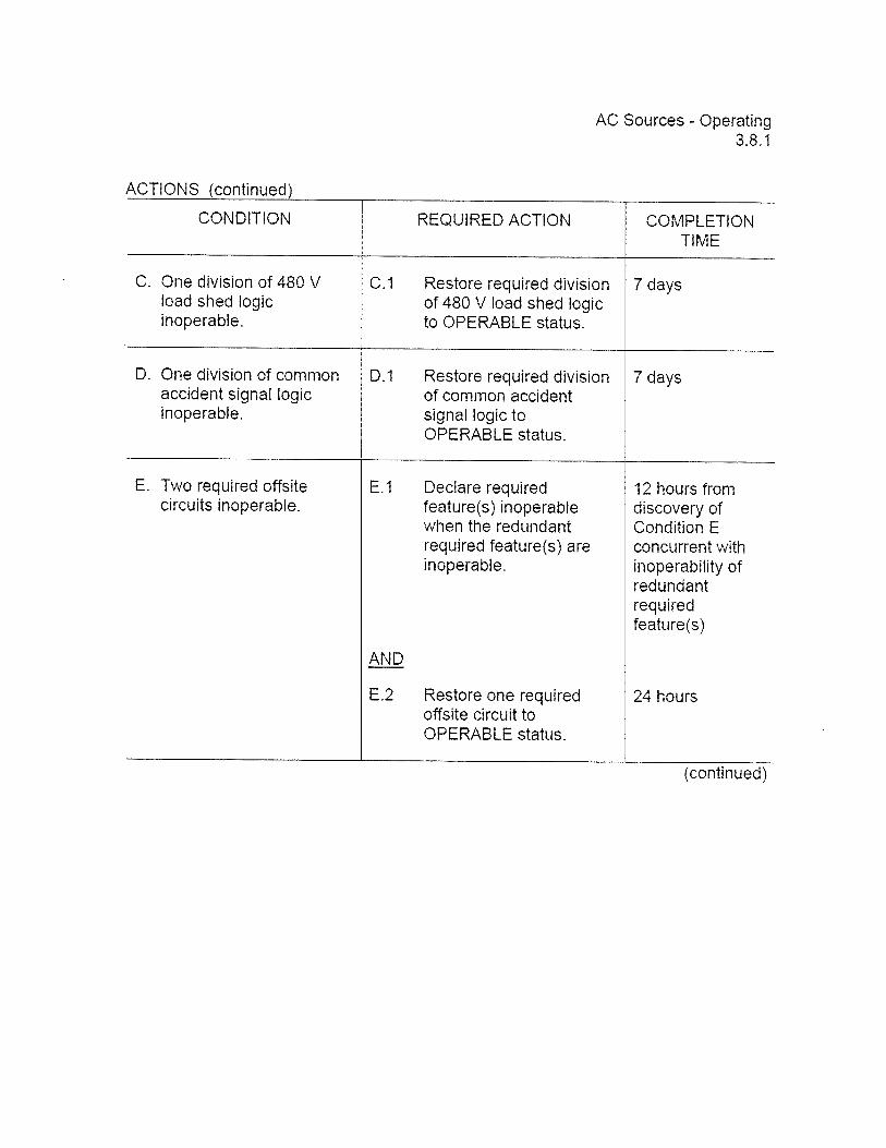
AC Sources - Operating3.8.1
3.8 ELECTRICAL POWER SYSTEMS
3.8.1 AC Sources - Operating
LCO 3.8.1 The following AC electrical power sources shall be OPERABLE:
a. Two qualified circuits between the offsite transmission networkand the onsite Class I E AC Electrical Power DistributionSystem:
b. Unit 1 and 2 diesel generators (DGs) with two divisions of480 V load shed logic and common accident signal logicOPERABLE: and
c. Unit 3 DG(s) capable of supplying the Unit 3 4.16 kV shutdownboard(s) required by LCO 3.8.7, “Distribution Systems -
Operating.
APPLICABILITY: MODES 1,2, and 3.
ACTIONS
NOTE•LCO 3.0.4.b is not applicable to DG5.
CONDITION REQUIRED ACTION COMPLETIONTIME
A. One required offsite A.1 Verify power availability 1 hourcircuit inoperable, from the remaining
OPERABLE offsite ANDtransmission network.
Once per 8 hoursthereafter
AND
(continued)
BFN-UNIT 1 3.8-1 Amendment No. 34 249December 1, 2003

AC Sources - Operating3.8.1
ACTIONS
CONDITION REQUIRED ACTION COMPLETIONTIME
B.2 Evaluate availability ofboth temporary dieselgenerators (TDGs).
AND
B.3 Declare requiredfeature(s), supported bythe inoperable Unit 1 and2 DG. inoperable whenthe redundant requiredfeature(s) are inoperable.
AND
1 hour
AND
Once per 12 hoursthereafter
4 hours fromdiscovery ofCondition Bconcurrent withinoperability ofredundant requiredfeature(s)
B.4.1 Determine OPERABLEUnit 1 and 2 DG(s) arenot inoperable due tocommon cause failure.
B.4.2 PerrormSR3.8.1.1 forOPERABLE Unit 1 and 2DG(s).
AND
B. (continued)
OR
24 hours
24 hours
(continued)

AC Sources - Operating3.8.1
ACTIONS
CONDITION REQUIRED ACTION COMPLETIONTIME
B. (continued) 8.5 Restore Unit 1 and 2 DG 7 days fromto OPERABLE status. discovery of
unavailability ofTDG(s)
AND
24 hours fromdiscovery ofCondition B entry>6 daysconcurrent withunavailability ofTDG(s)
AND
14 days
AND
21 days fromdiscovery offailure to meetLCO
(continued)
AC Sources - Operating3.8.1
ACTIONS (continued)
CONDITION REQUIRED ACTION COMPLETIONTIME
C. One division of 480 V 0.1 Restore required division 7 daysload shed logic of 480 V load shed logicinoperable, to OPERABLE status.
D. One division of common D.1 Restore required division 7 daysaccident signal logic of common accidentinoperable, signal logic to
OPERABLE status.
E. Two required offsite E.1 Declare required 12 hours fromcircuits inoperable, feature(s) inoperable discovery of
when the redundant Condition Erequired feature(s) are concurrent withinoperable. inoperability of
redundantrequiredfeature(s)
AND
E.2 Restore one required 24 hoursoffsite circuit toOPERABLE status.
(continued)

AC Sources - Operating3.8.1
ACTIONS (continued)
CONDITION REQUIRED ACTION COMPLETIONTIME
NOTE NOTEOnly applicable when more Enter applicable Conditions andthan one 4.16 kV shutdown Required Actions of LCD 3.8.7,board is affected. ‘Distribution Systems -
Operating,” when Condition F isentered with no AC power source
F. One required offsite to any 4.16 kV shutdown board.circuit inoperable.
AND F.1 Restore required offsite 12 hourscircuit to OPERABLE
One Unit 1 and 2 DG status.inoperable.
OR
F.2 Restore Unit 1 and 2 DG 12 hoursto OPERABLE status.
NOTEApplicable when only one4.16 kV shutdown board isaffected.
G. One required offsite G.1 Declare the affected Immediatelycircuit inoperable. 4.16 kV shutdown board
inoperable.AND
One Unit 1 and 2 DGinoperable.
(rrntir irf

AC Sources - Operating3.8.1
ACTIONS (continued)
CONDITION REQUIRED ACTION COMPLETIONTIME
H. Two or more Unit 1 H.1 Restore all but one Unit 1 2 hoursand 2 DGs and 2 DG to OPERABLEinoperable, status,
Required Action and 1.1 Be in MODE 3. 12 hoursAssociatedCompletion Time of LINPCondition A B, C, D,E, F. or H not met. 1.2 Be in MODE 4. 36 hours
J. One or more required J.1 Enter LCO 3.0.3. Immediatelyoffsite circuits andtwo or more Unit 1and 2 DGsinoperable.
OR
Two required offsitecircuits and one ormore Unit 1 and 2DGs inoperable.
OR
Two divisions of480 V load shed logicinoperable.
OR
Two divisions ofcommon accidentsignal logicinoperable.
(continued)
BFN-UNIT 1 3.8-6 Amendment No. 234

I BFN I EMERGENCY CLASSIFICATION PROCEDURE I Rev. 0049I EPIP-1
UnitO I PAGE 15 OF 205
6.0 EVENT CLASSIFICATION INDEX
SECTION 1.0 REACTOR 1.1 WATER LEVEL1.2 SCRAM FAILURE1.3 REACTOR COOLANT ACTIVITY1.4 MSLIOFFGAS RADIATION1.5 LOSS OF DECAY HEAT REMOVAL
SECTION 2.0 PRIMARY 2.1 PRIMARY CONTAINMENT PRESSURECONTAINMENT 2.2 PRIMARY CONTAINMENT HYDROGEN
2.3 DRYWELL RADIATION2.4 DRYWELL INTERNAL LEAKAGE2.5 LOSS OF PRIMARY CONTAINMENT
SECTION 3.0 SECONDARY 3.1 SECONDARY CONTAINMENTCONTAINMENT TEMPERATURE
3.2 SECONDARY CONTAINMENT RADIATION
SECTION 4.0 RADIOACTIVITY 4.1 GASEOUS EFFLUENTRELEASES 4.2 MAIN STEAM LINE BREAK
4.3 LIQUID EFFLUENT
SECTION 5.0 LOSS OF POWER 5.1 LOSS OF AC POWER5.2 LOSS OF 250V DC POWER
SECTION 6.0 HAZARDS 6.1 RADIOLOGICAL6.2 CONTROL ROOM EVACUATION
. 6.3 TURBINE FAILURE6.4 FIREIEXPLOSION6.5 TOXIC GASES6.6 FLAMMABLE GASES6.7 SECURITY6.8 VEHICLE CRASH6.9 SPENT FUEL STORAGE
SECTION 7.0 NATURAL EVENTS 7.1 EARTHQUAKE7.2 TORNADO1HIGH WINDS7.3 FLOOD
SECTION 8.0 EMERGENCY 8.1 TECHNICAL SPECIFICATIONSDIRECTOR 8.2 LOSS OF COMMUNICATIONJUDGMENT 8.3 LOSS OF ASSESSMENT CAPABILITY
8.4 OTHER
LAST PAGE

I EPIP-1 II BFN EMERGENCY CLASSIFICATION PROCEDURE I Rev. 0049 IUnito I PAGE 16 OF 205 I
THIS PAGE INTENTIONALLY BLANK

I EPIP-1I BFN EMERGENCY CLASSIFICATION PROCEDURE Rev. 0049 JUnit 0 EVENT CLASSIFICATION MATRIX I PAGE 17 OF 205
REACTOR10

BFN EMERGENCY CLASSIFICATION PROCEDURE R0049Unit 0 EVENT CLASSIFICATION MATRIX PAGE 18 OF 205
NOTES
1 .1-U 111.1 -Al Applicable when the Reactor Head is removed and the Reactor Cavity is flooded.
1.1-SI Applicable in Mode 5 when the Reactor Head is installed.
1 .1-G2 The reactor will remain subcritical under all conditions without boron when:• Any 19 control rods are inserted to position 02, with all
other control rods fully inserted.• All control rods except one are inserted to or beyond position 00.• Determined by Reactor Engineeiing.
CURVESITABLES:
TABLE 1.1 -G2MINIMUM ALTERNATE RPV FLOODING PRESS (MARFP)
NUMBER OF OPEN MSRVs MARFP (PSIG)
6orMore 1905 2304 290

I EPIP-1I BFN EMERGENCY CLASSIFICATION PROCEDURE I Rev. 0049Unit 0 EVENT CLASSIFICATION MATRIX I PAGE 19 OF 205
WATER LEVELDescription Description
1.1-oil I NOTE I 1.1-1121 IUncontrolled water level decrease in Reactor Uncontrolled water level decrease in Spent FuelCavity with irradiated fuel assemblies expected to Pool with irradiated fuel assemblies expected to zremain covered by water. remain covered by water.
C>I-
OPERATING CONDITION: OPERATING CONDITIONMode 5 ALL
1.1-All INOTEI i.i-A21Uncontrolled water level decrease in Reactor Uncontrolled water level decrease in Spent FuelCavity expected to result in irradiated fuel Storage Pool expected to result in irradiated fuelassemblies being uncovered, assemblies being uncovered.
OPERATING CONDITION: OPERATING CONDITION: -.4
Mode 5 ALL
1.1-SI I INOTEI I 1.1-521 IReactor water level can NOT be maintained Reactor water level can NOT be determined.above -162 inches. (TAF)
mm
J0m
OPERATING CONDITION: OPERATING CONDITION:ALL Model or2or3 -<
l.1-G1 I I 1.1-G2 I I NOTE I TABLE IReactor water level can NOT be restored and Reactor water level can NOT be determinedmaintained above -180 inches. AND
Either of the following exists:. The reactor will remain subcritical without boron
under all conditions, and“ Less than 4 MSRVs can be opened, or Z‘ Reactor pressure can NOT be restored and
maintained above Suppression Chamberpressure by at least 70 psi.
. It has NOT been determined that the reactor willremain subcritical without boron under all niconditions and unable to restore and maintainMARFP in Table l.l-G2.
zOPERATING CONDITION: 0Modelor2or3
OPERATING CONDITION:Model or2or3

BFN I EMERGENCY CLASSIFICATION PROCEDURE IRev. 0049
Unit 0 EVENT CLASSIFICATION MATRIX PAGE 20 OF 205
NOTES1.2 Subcritical is defined as reactor power below the heating range and not trending upward.
CURVESITABLES:
CURVE t.2-GHEAT CAPACITY TEMP LIMIT
RXfFESS *
3BtLOWTOP.>5
UI
UI
SUPPR P. LVL T)ACTONREQUIRDIAUI3..UR Oh STI(..A UI.

I BFN EMERGENCY CLASSIFICATION PROCEDURE EPIP-1
Unit 0 EVENT CLASSIFICATION MATRIX I PAGE 21 OF 205I Rev. 0049
SCRAM FAILURE REACTOR COOLANT
___ ____ _______ __
ACTIVITYE
Ition
_____________
Descr
1.3-UI I I IReactor coolant activity exceeds 26 iCiIgm doseequivalent 1-131 (Technical Specification Limits) Zas determined by chemistry sample.
C
I-
OPERATING CONDITIONALL
1.2-Al INOTEI I 1.3-Al I I IFailure of RPS automatic scram functions to bring Reactor coolant activity exceeds 300 .tCiIgm dosethe reactor subcritical equivalent lodine-131 as determined by chemistry
AND sample.I-
Manual scram or ARI (automatic or manual) was msuccessful.
OPERATING CONDITION:OPERATING CONDITION: Mode I or 2 or 3Model or2
1.2-SI INOTEI I IFailure of automatic scram, manual scram, andARI to bring the reactor subcritical. m
m
0mz
OPERATING CONDITION:Modelor2 -<
1.2-GICURVEI I I I I IFailure of automatic scram, manual scram, andARI. Reactor power is above 3% 0
AND
Either of the following conditions exists:. Suppression Pool temp exceeds HCTL. in
Refer to Curve 1.2-G.. Reactor water level can NOT be restored
and maintained at or above -180 inches.mz
OPERATING CONDITION:Mode 1 or 2

BFN I EMERGENCY CLASSIFICATION PROCEDURE 1 Rev. 0049Unit 0 EVENT CLASSIFICATION MATRIX I PAGE 22 OF 205
NOTES
CURVES/TABLES:
CURVE 15SHEAT CAPACITY TEMP LIMIT
U,
SLPR RL LVL FT)

I EPIP-1BFN EMERGENCY CLASSIFICATION PROCEDURE I Rev. 0049Unit 0 EVENT CLASSIFICATION MATRIX I PAGE 23 OF 205
1.4—U I I I I I I I IValid MAIN STEAM LINE RADIATION HIGH-HIGHalarm, 1, 2, or 3-RA-90-135C
OR>
Valid OG PRETREATMENT RADIATION HIGHalarm, 1, 2, or 3-RA-90-157A.
mOPERATING CONDITION: Z
Modelor2or3
1.5—A I I I IReactor moderator temperature can NOT bemaintained below 2120 F whenever TechnicalSpecifications require Mode 4 conditions or duringoperations in Mode 5. rrn
OPERATING CONDITION:Mode 4 or 5
1.5-SICURVEI I ISuppression Pool temperature, level and RPVpressure can NOT be maintained in the safe area jof Curve 1.5-S. m
m
;C)m
OPERATING CONDITION:Modelor2or3
I I IC)mzm
mm
mzC)-<

I Rev. 0049I BFN I EMERGENCY CLASSIFICATION PROCEDURE I EPIP-1
Unit 0 EVENT CLASSIFICATION MATRIX I PAGE 24 OF 205
THIS PAGE INTENTIONALLY BLANK

I Rev. 0049BFN I EMERGENCY CLASSIFICATION PROCEDURE EPIP-i
Unit 0 EVENT CLASSIFICATION MATRIX I PAGE 25 OF 205
PRIMARYCONTAINMENT
2.0

BFN EMERGENCY CLASSIFICATION PROCEDURE EPIP-1
Unit 0 EVENT CLASSIFICATION MATRIX PAGE 26 OF 205
NOTES
CURVESITABLES:
TABLE 2.1-ArnINDICATIONS OF PRIMARY SYSTEM LEAKAGE
INTO PRIMARY CONTAINMENTPrimary Containment Pressure High AlarmDrywell Ftoor Drain Sump Pump Excessive OperationDrywell CAM Activity IncreasingDrywell Temperature High AlarmChemistry Sample Radionuclide Comparison To Reactor Water

I EPIP-1‘ BFN EMERGENCY CLASSIFICATION PROCEDURE I Rev. 0049Unit 0 EVENT CLASSIFICATION MATRIX I PAGE 27 OF 205
PRIMARY CONTAINMENT PRIMARY CONTAINMENTPRESSURE HYDROGENII [iIiJJ)n
I
______
I ICzC0C>Immz-I
2.1-Al I ITABLEI I IDrywell pressure at or above 2.45 psig
ANDr
Indication of Primary System leakage into mPrimary Containment. Refer to Table 2.1-A.
OPERATING CONDITION:Model or2or3
2.1-S ICURVEI 2.2-S I ISuppression Chamber pressure can NOT be Drywell or Suppression Chambermaintained in the safe area of Curve 2.1-S. hydrogen concentration at or above 4%
mAND
Drywell or Suppression Chamberoxygen concentration at or above 5%.
OPERATING CONDITION: OPERATING CONDITION:Mode 1 or 2 or 3 Mode I or 2 or 3 -<
2.1—GI 2.2-GI ISuppression Chamber pressure can NOT be Drywell or Suppression Chambermaintained below 55 psig. hydrogen concentration at or above 6%
AND
Drywell or Suppression Chamberoxygen concentration at or above 5%. m
m
mOPERATING CONDITION: OPERATING CONDITION:Mode 1 or 2 or 3 Mode 1 or 2 or 3
I

U,
00)0
)0)0)
00
)(‘3
C%J(‘3
0)
co
-
WQ
LU
zO
C’3
C)
a.D
OC
’1C
)Z
‘‘
ZI-z
LUZ
CC
Ui
ZC
Z000
Ui
z0O
DQ
C)
Zc)c)
LU
0z
C.)C.)
zw
x0
>.>-
F-a’
z0
10
00
I-U
)
wX
c’,o
otc,
C.)a’
co
co
00
,za.
c.,z
IU,l_zw
c4O
LU
cQ
9C
?0
02(9
c;c.1
F-a.
CilU
.
0cS
àU
J
<w
i..°?°‘
Ui,..
°°?
I-_i
ww
oW
Wu.
a’>
-zcç
oa,
EC
NC
’3(l)
UJ
cc’J
Ui>
UJ
(I)Lii
U)
0U
)0
0‘I
Ic..JcN
Lu
III-
oJO
Cl)C
O
IDía
C)
DO
cjc
’D
Occ
ZC
00
00
00
000
a)
w0
?O
?w
ww
ailiii
>i—I01
Dzi
C.)
C

I Rev. 0049I BFN EMERGENCY CLASSIFICATION PROCEDURE I EPIP-1
Unit 0 EVENT CLASSIFICATION MATRIX I PAGE 29 OF 205
DRYWELL RADIATION
__________
LJescI ion
I I IzCC’)C>Im<mz-•1
2.3-Al ITABLEIUS I IDrywell radiation levels at or above the valueslisted in Table 2.3-A/2.3-S2, with the RCS barrierintact inside Primary Containment.
Im-I
OPERATING CONDITION:Model or2or3
2.3-SI I I I TABLE I US 2.3-S2 I I I TABLE I USDrywell radiation levels at or above the values Drywell radiation levels at or above the valueslisted in Table 2.3-S112.3-G2 with the RCS barrier listed in Table 2.3-A12.3-S2, with the RCS barrierNOT intact inside Primary Containment, intact inside Primary Containment,
AND mEither of the following exists: m. Indications of loss of Primary Containment.
Refer to Table 2.312.5-U.. Primary Containment integrity can NOT be G)
maintained.0
OPERATING CONDITION: OPERATING CONDITION: -<Model or2or3 Model or2or3
2.3-GI I I TABLE I US 2.3-G2 I I TABLE I USDrywell radiation levels at or above the values Drywall radiation levels at or above the values C)listed in Table 2.3-G1 with the RCS barrier NOT listed in Table 2.3-S112.3-G2 with the RCS barrier mintact inside Primary Containment. NOT intact inside Primary Containment, Z
AND rnEither of the following exists:. Indications of loss of Primary Containment.
Refer to Table 2.3/2.5-U.. Primary Containment integrity can NOT be m
maintained.
OPERATING CONDITION: OPERATING CONDITION: C)Mode I or 2 or 3 Mode 1 or 2 or 3
Desci n
I I

‘to
O
LU
0
I-U
izLU
oz
V0c
I-a)
z01—
0r.)a)
>-
Cl)
QQC.)
I_-I
-_
JU
.U0
oh
>1-
Cl)’
0zZog
0U
i>(u
jU
i0
Ui
_•.a
)u
)
Cl)’W
I
i U)
‘
Cl)U
iWI
>0)
I-I01
cx
cU
C.)D
W.
t.

I EPIP-1I BFN EMERGENCY CLASSIFICATION PROCEDURE I Rev. 0049Unit 0 EVENT CLASSIFICATION MATRIX I PAGE 31 OF 205
DRYWELL INTERNAL LOSS OF PRIMARYLEAKAGE CONTAINMENT
Description uescription
2.4-U I I I I 2.5-U I I ITABLEI
Drywell unidentified leakage exceeds 10 gpm Inability to maintain Primary Containmentpressure boundary. Refer to Table 2.3/2.5-U. z
ORC
Drywell identified leakage exceeds 40 gpm.
OPERATING CONDITION: OPERATING CONDITION: mMode 1 or 2 or 3 Mode 1 or 2 or 3
2.4—A I I I I I I IDrywell unidentified leakage exceeds 50 gpm.
>Fm-I
OPERATING CONDITION:Model or2or3
I I I I I I ICo-Imin
in
C)inzC,-<
I I I I I I I0inzin
Fin
in
0inzC,-<

BFN EMERGENCY CLASSIFICATION PROCEDURE EPIP-1I Rev. 0049
Unit 0 EVENT CLASSIFICATION MATRIX I PAGE 32 OF 205
THIS PAGE INTENTIONALLY BLANK

I EPIP-1 II BFN EMERGENCY CLASSIFICATION PROCEDURERev. 0049 I
Unit 0 EVENT CLASSIFICATION MATRIX I PAGE 33 OF 205 I
SECONDARYCONTAINMENT
3.0

-Il
-o C)I x > 0)
I CD ci I x 0 3
IC) C x a)
C)
C x m x ci C C) IC-
)C CD C
, -a C 3
C) C 0 C C.
U) 0 < > a)
I -u C) —I
C 2- I.
I -D C)
(1)
CD a) 3 C’)
C 0)
C)
C)
C’)
CD a) 3 CI)
a)
I CD ci -U C 3 0 3
I C.)
-o C 3 0 0 3
1Z
1 C (I) 0 F 0 CD C) C)
a) CD CD —I
CD 3
z 0 -l m cn
aa
I?
i:z
zau
1 CD3
00
-nC
C0
•3
33
0(l
)r 0)
D<
C CD CDCD
CD
0 3:
.
C) m
C)
C’)
C-)
C 3 0) D.
3 C) C) —4 c 2- CD CD a)
CD c7 -n
-.4
CD CT’
C
-4 CD C,’ C)
0)
CD
CD m
0) CP r’3 CD C
0)
CD CO 3:
0)
CD 1%)
CD G)
0)
CD CD -Ti
0)
C)
Oh
Wcri
C >0
31
CD
CD
0’
oT
’
3
-4 CD Oh m
cI
-.4
(ID G)
-.4 CD C,’ I
-.4
C.,
C)i
01 CD (.11
C,’ C) 01 01 ci
-1 CD C)
-& ci
-4-4--a
CC
D-0
1C
,1>
>C
D
-.4
CC
Zm
>Ii
i- r
0>
>•-
-lO
3m
m
c0
rZ
mrn
mzr
ru
01- ci
C 0
m ‘ii
mz
coo,
o)
0 -10
C)
xm m
mm
rn
o0
.
1.
C,’
-M
FZ
000
31%
3T’3
Cr1000
-.4-4
-C
D..
CDCD
-•4
C,’
L
00
10
01
00
1-I C’
)
C z -I
_—
——
——
——
——
——
— C3I3—
Z0
iCD
CD
--)I\)
M-.0C
D4--C
fl—
CflC
3J1C
TI01000
O0
CX
,0
00
000001 M
1-.)
01
Ci)
>•T
1rm C
orn
-u I01C
D4
—C
)1C,
’C,
’010
00000
0101
C z -I CA)
-..(
‘3r\
)0
10
0C
r1
00
1)3
k)
01
00
0

I EPIP-1I BFN I EMERGENCY CLASSIFICATION PROCEDURE I Rev. 0049Unit 0 EVENT CLASSIFICATION MATRIX I PAGE 35 OF 205
SECONDARY CONTAINMENT TEMPERATUREuescnption
I I I I I
z0)
>Irnmz-I
I I I I I
>Im
3.1-SI I ITABLEIUSICo
An unisolable Primary System leak is discharging into Secondary Containmentm
AND
Any area temperature exceeds the Maximum Safe Operating Temperature limit listed in Table 3.1.
OPERATING CONDITION:Modelor2or3 -<
3.1-GI I ITABLEIUSI
An unisolable Primary System leak is discharging into Secondary Containment 0
AND
Any area temperature exceeds the Maximum Safe Operating Temperature limit listed in Table 3.1rn
ANDhi
Any indication of potential or significant fuel cladding failure exists. Refer to Table 3.1-G13.2-G withRCS Barrier intact inside Primary Containment. rn
zOPERATING CONDITIONMode 1 or2or3
G)
ci)
a)
C’)
CD 0 CD -n > a)
‘1 C CD -U 0 0 > CD 0)
z -n C CD C’) 5. CD
—1 -U D CD 0)
C) C ci)
Co CD 3 > a)
C) C) C m 0) CO 0)
or
Ci)
UZ ;u
c2og’
C)00
0 03
3
Ci)
0 C
z 00
(0
00C
0r1
-‘
‘r’’
CD
i’
Ci)
0J
Co
0C
om
o
3
z 0 3
Z 0 -I m C,)
C) C m Isly
C) —.
1 0
0 .0-.
0, C)
s-Iv
C)
—I-
I
——
..
0 0
0 eli
-.
0) C)
•Iv a
—.
-I
0>
Dl C)
V -L CD m 0 N)
—1 V N)
C)
m (ID a N)
-4 V -.
CD 0)
C z —I- C C 0 z C z -1 N
)
z zC
n0
0
mz
-t>
>0w 0Jr
coz
DI1
G)
z’s
0 Z G) I
V N)
CD -4 N)
m a N)
-4 V N)
CD -4 z CI)
m 0 0 —I V N)
CD -.4 3:
xl
b
C 0
m m
mz
Zn
mm
rn
CC
DC
DC
DC
DC
D(D
CO
000099999999999?
-
-N
)N
)N
)N
)N
)N
)N
)N
)N
)0
0C
O-1
O)3
0)C
J1
z>
:x’>
>>
>>
>>
>>
zi 0
-‘-
-A
LL
—-
-à
....L
——
-‘
.A
00
00
00
00
00
000000
z>
oooo000000000000X
000
00
00
00
000
0000
co
----
--
-TI
cm
L..
.L.L
.LL
.L.L
L..L
..L
LL
.L
z0ooaoooooooo
oo
oZ
<>
co
c,0
00
00
00
00
00
0Z
1>
0000
000
00
00000
N)r
--
--
a -4 ci,
Zo
oo
oc,o
oo
ooo
oo
oo
Zooo°000000000°
00
00
00
00
000000
i EPIP-1I BFN EMERGENCY CLASSIFICATION PROCEDUREI Rev. 0049
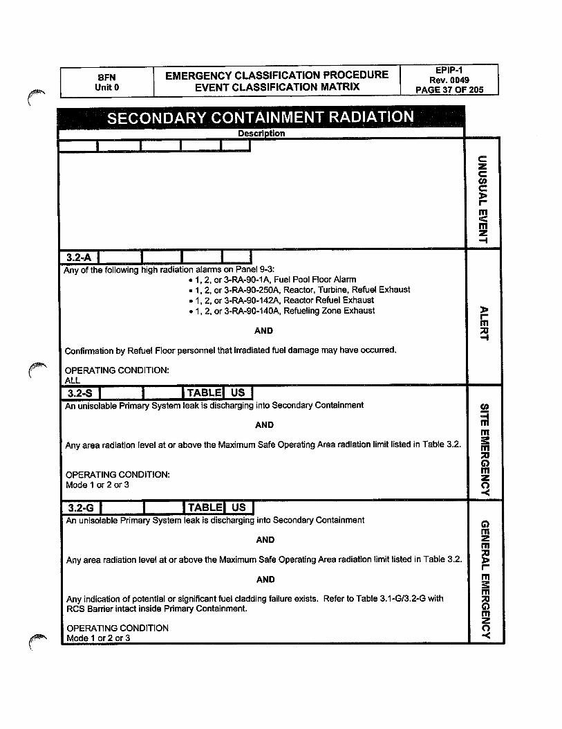
Unit 0 EVENT CLASSIFICATION MATRIX i PAGE 37 OF 205
SECONDARY CONTAINMENT RADIATIONuescnpuon
I I I I ICzC0C>Immz-I
3.2-Al I I I IAny of the following high radiation alarms on Panel 9-3:
• 1, 2, or 3-RA-90-IA, Fuel Pool Floor Alarm. 1, 2, or 3-RA-90-250A, Reactor, Turbine, Refuel Exhaust. 1, 2, or 3-RA-90-142A, Reactor Refuel Exhaust. 1 2, or 3-RA-90-140A, Refueling Zone Exhaust
ImAND
-I
Confirmation by Refuel Floor personnel that irradiated fuel damage may have occurred.
OPERATING CONDITION:ALL
3.2-S I I ITABLEI US IAn unisolable Primary System leak is discharging into Secondary Containment
-4AND m
mAny area radiation level at or above the Maximum Safe Operating Area radiation limit listed in Table 3.2.
0OPERATING CONDITION:Modelor2or3
-<
3.2-G I ITABLEI US IAn unisolable Primary System leak is discharging into Secondary Containment
mAND Z
Fri
Any area radiation level at or above the Maximum Safe Operating Area radiation limit listed in Table 3.2.r
AND
Any indication of potential or significant fuel cladding failure exists. Refer to Table 3.1-G13.2-G withRCS Barrier intact inside Primary Containment.
OPERATING CONDITIONModelor2or3 -<

I EPIP-1I BFN EMERGENCY CLASSIFICATION PROCEDURE I Rev. 0049UnIt 0 EVENT CLASSIFICATION MATRIX I PAGE 38 OF 205
THIS PAGE INTENTIONALLY BLANK

.I EPIP-1
BFN EMERGENCY CLASSIFICATION PROCEDURE I Rev. 0049Unit 0 EVENT CLASSIFICATION MATRIX I PAGE 39 OF 205
RADIOACTIVITYRELEASES
4M

f EPIP-1I BFN I EMERGENCY CLASSIFICATION PROCEDUREI Rev. 0049
Unit 0 EVENT CLASSIFICATION MATRIX I PAGE 40 OF 205
NOTES4.1-U Pñorto making this emergency classification based upon the WRGERMS incficafion, assess the release by either of the following:
ifidual field measuremen ceed the limits intabte4.l-U
2.0-SI 4.8.B.1 .a.l release fraction exceeds 2.0
if neither assessment can be cendocted within 60 minutes then the declaration must be made on the valid WRGERMS reading.
4.1-A Prior to making this emergency classification based upon the WRGERMS indication, assess the release by either of the following:
1. Actual field measurements exceed the limits in table 4.1-A
2.0-SI 4.8.B.1.a.1 release fraction exceeds 200
If neither assessment can be conducted within 15 minutes then the declaration must be made on the valid WRGERMS reading.
4.1-S Prior to making this emergency classification based upon the gaseous release rate indication, assess the release by eHrer of the
following methods:1. Actual field measurements exceed the limits in table 4.1-S.
2. Prceded or actual dose assessments exceed 100 mrem TEDE or 500 mrem CDE.
If neither assessment can be conducted within 15 minutes then the declaration must be made based on the valid WRGERMS reading.
4.1-G Prior to making this emergency classification based upon the gaseous release rate indication, assess the release by either of the
following methods:1. Actual field measurements exceed the limits in table 4.1-G.
2. Pneded or actual dose assessments exceed 1000 mrem TEDE or 5000 mrem CDE.
If neither assessment can be conducted within 15 minutes then the declaration must be made based on the valid WRGERMS reading.
CURVES!TABLES:Table 4.1-U
RELEASE LIMITS FOR UNUSUAL EVENT
Table 4.1-SEASE LIMITS FOR SITE ARE EMERGENCYREI—
Table 4.1-ARELEASE LIMITS FOR?MONITORING METHOD
Stack Noble Gas (WRGERMS)
IVHJNI I JIII1I3 I I FIJU
Stack Noble Gas (WRGERMS)
Field Assessment Team
Field Assessment Team
0-SI 4.8.B.1.a.1
Field Assessment Team
LERTLIMIT
UMIT
TYPE MONITORING METHOD LIMIT DURATION
Gaseous Release Rate Stack Noble Gas (WRGERMS) 2.88 X pCi/sec 1 Hour
Gaseous Release Rate 0-SI 4.8.B.1.a.1 Release Fraction 2.0 1 Hour
Site Boundary Radiation Reading Field Assessment Team 0.10 MREMIHR Gamma 1 Hour
TYPE
Gaseous Release Rate
Gaseous Release Rate
Site Boundary Radiation Reading
2.88 X 10 ° iiCi/sec
TYPE
Gaseous Release Rate
DURATION
Release Fraction 200
15 Minutes
10 MREM/HR Gamma
Site Boundary Radiation Reading
15 Minutes
Site Boundary Iodine-131
15 Minutes
5.9 X 10 pCi/sec
DURATION
100 MREM/HR Gamma
15 Minutes
3.9X lO7jiCl/cm3
1 Hour
1 Hour
Table 4.1-CRELEASE UMITS FOR GENERA’ EMERGENCY
TYPE MONITORING METHOD LIMIT DURATION
Gaseous Release Rate Stack Noble Gas (WRGERMS) 5.9 X 10 10 pCi/sec 15 Minutes
Site Boundary Radiation Reading Field Assessment Team 1000 MREM/HR Gamma 1 Hour
Site Boundary Iodine-131 Field Assessment Team 3.9 X 10 pCI I cm3 1 Hour

I EPIP-iI BFN I EMERGENCY CLASSIFICATION PROCEDURERev. 0049
Unit 0 EVENT CLASSIFICATION MATRIX PAGE 41 OF 205
GASEOUS EFFLUENTDescription
4.1-U I I NOTE I TABLEI Ia
Gaseous release exceeds ANY limit and duration in Table 4.1-U. zC0C>Im<
OPERATING CONDITION: mALL Z
-I
4.1-A I I NOTE ITABLEI IGaseous release exceeds ANY limit and duration in Table 4.1-A.
>Im
OPERATING CONDITION:ALL
4.1-S I INOTEITABLEI I.
0EITHER of the following conditions exists:
. Gaseous release exceeds or is expected to exceed ANY limit and duration in Table 4.1-S.
. Dose assessment indicates actual or projected dose consequencesabove 100 rnrem TEDE or 500 mrem thyroid CDE.
OPERATING CONDITION:ALL -<
4.1-GI INOTEITABLEI IEITHER of the following conditions exists:
. Gaseous release exceeds or is expected to exceed ANY limit and duration in Table 4.1-G.
. Dose assessment indicates actual or projected dose consequencesabove 1000 mrem TEDE or 5000 mrem thyroid CDE.
m
OPERATING CONDITIONALL
-C
I EPIP-1BFN EMERGENCY CLASSIFICATION PROCEDURE L Rev. 0049
Unit 0 EVENT CLASSIFICATION MATRIX I PAGE 42 OF 205
NOTES
CURVESITABLES:

I EPIP-1I BFN EMERGENCY CLASSIFICATION PROCEDURE I Rev. 0049Unit 0 EVENT CLASSIFICATION MATRIX I PAGE 43 OF 205
MAIN STEAM LINE LIQUID EFFLUENT
BREAKtion
I
____________
Description
___________
4.3-UI I I ILiquid release rate exceeds 20 times ECL as
Main Steam Line break outside determined by chemistry sample z
Primary Containment with isolation..
AND c>
Release duration exceeds or will exceed60 minutes.
mOPERATING CONDITION: OPERATING CONDITION: Z
Model or2or3 ALL—I
I I 4.3-Al I ILiquid release rate exceeds 2000 times ECLas determined by chemistry sample
ANDI-
Release duration exceeds or will exceed15 minutes.
OPERATING CONDITION:ALL
4.2-SI I I I I I I
Unisolable Main Steam Line break outsidePrimary Containment. m
m
6)mOPERATING CONDITION:Model or2or3 -<
I I I I I I6)mz‘ii
ImrTl;6)rTizC,-<
4.2-U I

I EPIP-1F BFN EMERGENCY CLASSIFICATION PROCEDURE I Rev. 0049Unit 0 EVENT CLASSIFICATION MATRIX I PAGE 44 OF 205
THIS PAGE INTENTIONALLY BLANK

.I EPIP-1
BFN I EMERGENCY CLASSIFICATION PROCEDURE I Rev. 0049Unit EVENT CLASSIFICATION MATRIX I PAGE 45 OF 205
LOSS OF POWER5.0

BFN EMERGENCY CLASSIFICATION PROCEDURE R0049Unit 0 EVENT CLASSIFICATION MATRIX PAGE 46 OF 205
NOTES
5.1-U Loss of normal and alternate supply voltage implies inability to restore voltage from any qualified source
to normal or alternate feeder for at least one of the unit specific boards within 15 minutes. At least two
boards must be energized from Diesel power to meet this classification. If only one board can be
energized and that board has only one source of power then refer to EAL 5.1-Al or 5.1-A2.
5.1-Al Only one source of power (Diesel or Offsite) is available to any one of the listed unit specific 4KVShutdown Boards. No power is available to the three remaining boards.
5.1 -A2 Loss of voltage to all unit specific 4KV Shutdown Boards applies to those boards which normally supplyemergency AC power to the affected unit only. Determination of the event classification depends on the
affected unit operating mode. For units in operation 5.1-S would apply.
5.1-S Loss of voltage to all unit specific 4KV Shutdown Boards applies to those boards which normally supplyemergency AC power to the affected unit only. Determination of the event classification depends on theaffected unit operating mode. For units in Shutdown or Refuel 5.l-A2 would apply.
5.1 -G Loss of voltage to all unit specific 4KV Shutdown Boards applies to those boards which normally supplyemergency AC power to the affected unit only.
CURVESITABLES:
Table 5.1UNIT 4KV SHUTDOWN BOARD APPLICABILITY
APPLICABLE UNIT APPLICABLE 4KV SHUTDOWN BOARDSUNIT 1 A, B, C, and DUNIT2 A, B, C, andDUNIT 3 3A, 3B, 3C, and 3D

I Rev. 0049Unit 0 EVENT CLASSIFICATION MATRIX I PAGE 47 OF 205 1
I BFN EMERGENCY CLASSIFICATION PROCEDUREI EPIP-1
5.1-U I tITABLEI US I I I ILoss of normal and supply voltage to ALLunit specific 4KV shutdown boards from Table 5.1 zfor greater than 15 minutes C
AND CAt least two Diesel Generators supplying power tounit specific 4KV shutdown boards listing inTable 5.1.OPERATING CONDITION: mALL
5.1-Al I I NOTE I TABLE I US 5.1-A2 I I NOTE I TABLE I USLoss of voltage to ANY THREE unit specific 4KV Loss of voltage to ALL unit specific 4KV shutdownshutdown boards from Table 5.1 for greater than boards from Table 5.1 for greater than 15 minutes.15 minutes
I-Only ONE source of power available to the mremaining board.
OPERATING CONDITION: OPERATING CONDITION:Mode 1 or 2 or 3 Mode 4 or 5 or Defueled
5.1-S I I NOTE ITABLEI US I I I ILoss of voltage to ALL unit specific 4KV shutdownboards from Table 5.1 for greater than 15 minutes.
inm
G)inzC)
OPERATING CONDITION: -<Model or2or3
5.1-G I I NOTE ITABLEI US I I ILoss of voltage to ALL unit specific 4KV shutdown G)boards from Table 5.1 FR
AND FREither of the following conditions exists;. Restoration of at least one 4KV shutdown board F.
is NOT likely within three hours. FR. Adequate core cooling can NOT be assured.
FR
mz
OPERATING CONDITION:Mode 1 or 2 or 3

BFN EMERGENCY CLASSIFICATION PROCEDURE R0049• Unit 0 EVENT CLASSIFICATION MATRIX PAGE 48 OF 205
NOTES
52 250V DC power voltage below 248 volts constitutes a loss of DC power to the affected board. The
voltage readings may be obtained at the 250V Shutdown Battery Board (or the 250V Plant Battery Board)
that is feeding the affected board.
CURVES1TABLES:
Table 5.2-UUNIT 4KV SHUTDOWN BOARD APPLICABILITY
APPLICABLE UNIT APPLICABLE 4KV SHUTDOWN BOARDSUNIT 1 A, B, C,ANDDUNIT2 A, B, C,ANDD
. UNIT 3 3A, 3B, 3C, AND 3D
Table 5.2-SCRITICAL DC POWER AND ESSENTIAL SYSTEMS
COMBINATION LOSS OF CRITICAL 250V DC POWER POTENTIALLY RESULTS(Unit Specific Unless Otherwise Noted) IN
I Control Power for 4KV Unit Boards A, B, and C Loss of Main Condenser
AND AND
Control Power for 480V Unit Boards A and B Loss of Both EHC Pumps
AND AND
Power for Panel 9-9 Cabinet I Loss of All Reactor FeedPumps
II Power for 250V DC RMOV Board A Loss of HPCI
III Power for 250V DC RMOV Board C Loss of RCIC
IV Power for 250V DC RMOV Boards A, B, and C Less than 4 MSRVs
AND AND
Control Power for 4KV Shutdown Boards A, B, C, and D Loss of All RHR Pumps(4KV Shutdown Boards 3A, 3B, 3C, and 3D for Unit 3) And Core Spray Pumps

BFN I EMERGENCY CLASSIFICATION PROCEDURE I EPIP-1I Rev. 0049
Unit 0 EVENT CLASSIFICATION MATRIX I PAGE 49 OF 205
L
5.2-U 1 ITABLEI US I I I IUnplanned loss of 2 .1 DC control power to ALL
unit specific 4KV shutdown boards from zTable 5.2-U for greater than 15 minutes
OR cUnplanned loss of 250V DC control power to unitspecific 480V shutdown boards A and B I.—
for greater than 15 minutes.m
OPERATING CONDITION: Z
Modes4or5—I
I I I I I I I
)IIm
5.2-S I I NOTE ITABLEI US I I ILoss of 250V DC power to ALL combinations(I, II, III, and IV) of essential systems fromTable 5.2-S for greater than 15 minutes.
m
;6)mzC,
OPERATING CONDITION:Mode 1 or 2 or 3
I I I I I I6)mzrTi
Imm
6)niC,-<

I EPIP-1BFN I EMERGENCY CLASSIFICATION PROCEDURE Rev. 0049
Unit 0 EVENT CLASSIFICATION MATRIX PAGE 50 OF 205 a
THIS PAGE INTENTIONALLY BLANK

I EPIP.1I BFN I EMERGENCY CLASSIFICATION PROCEDURE Rev. 0049Unit 0 EVENT CLASSIFICATION MATRIX I PAGE 51 OF 205
HAZARDS

I EPIP-1I BFN EMERGENCY CLASSIFICATION PROCEDURE I Rev. 0049Unit 0 EVENT CLASSIFICATION MATRIX I PAGE 52 OF 205
NOTES
CURVESITABLES:

I BFN EMERGENCY CLASSIFICATION PROCEDUREI EPIP-1
Rev. 0049
UnIt 0 EVENT CLASSIFICATION MATRIX I PAGE 53 OF 205
RADIOLOGICALuescription uescription
6.1—U I I I I I I I I
Valid, unexpected increase of ANY in-plant ARMreading to 1000 mrem/hr (except TIP room).
C
I
I
mOPERATING CONDITION:ALL Z
6.1-All I I 6.l-A21 I I I
Valid, unexpected increase of ANY in-plant ARM Control Room radiation levels greater thanreading to 1000 mrem/hr (except TIP room). 15 mrem/hr.
rPersonnel required in the affected area(s). m
-I
OPERATING CONDITION: OPERATING CONDITION:ALL ALL
I I I IC’)
-I‘ii
mm
G)mzC)-<
I IG)I,’z‘ii
IFT1
rn
‘IizC,-<

I EPIP-1BFN I EMERGENCY CLASSIFICATION PROCEDURE I Rev. 0049
Unit 0 EVENT CLASSIFICATION MATRIX I PAGE 54 OF 205
NOTES
CURVESITABLES:
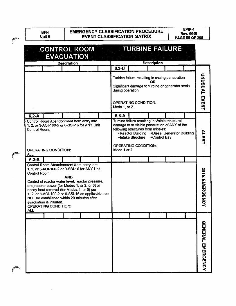
EPIP-1I BFN I EMERGENCY CLASSIFICATION PROCEDURE Rev. 0049Unit 0 EVENT CLASSIFICATION MATRIX I PAGE 55 OF 205
CONTROL ROOM TURBINE FAILUREEVACUATION
______
I ITurbine failure resulting in casing penetration
ORSignificant damage to turbine or generator sealsduring operation.
I-
OPERATING CONDITION:Model,or2
6.2-Al I I 6.3-Al I IControl Room Abandonment from entry into Turbine failure resulting in visible structural1, 2, or 3-AOl-I 00-2 or 0-SSI-l 6 for ANY Unit damage to or visible penetration of ANY of theControl Room. following structures from missles:
‘Reactor Building ‘Diesel Generator Building r‘Intake Structure ‘Control Bay m
OPERATING CONDITION:OPERATING CONDITION: Model or 2ALL
6.2—S I I IControl Room Abandonment from entry into1, 2, or 3-AOI-l00-2 or 0-SSI-16 for ANY UnitControl Room
AND mControl of reactor water level, reactor pressure, mand reactor power (for Modes 1, or 2, or 3) or mdecay heat removal (for Modes 4, or 5) per1, 2, or 3-AOl-i 00-2 or 0-SSI-l 6 as applicable, can G)NOT be established within 20 minutes afterevacuation is initiated. aOPERATING CONDITION: -<ALL
I I IG)Illzm
rI1
m
rnzC,..<
Desci non
I 6.3-U I

U,
‘zoO
W0W
LUwx
0-
00
D
._J
—I_
i0.
0.
0
ZL
IJ(D
O-
-
E>
0Z
E>
OZ
o<
ou,
0o,
-L
LJa,o
LU0E
—oC
C
E°
LUO
OO
EC
<Ø
___
4-
__
__
0C
Cl,LU
CC
Dc
(oC
t,
o••
uoC
v0a
.-
0cc
CC
Cl,i.
ILZ
C,,LU
WI>
I-Io
lDC
.)ooöi-.9roco

EPIP-1I BFN I EMERGENCY CLASSIFICATION PROCEDURE Rev. 0049Unit 0 EVENT CLASSIFICATION MATRIX I PAGE 57 OF 205
6.4-UI I I I TABLE I 6.4-U2 I I I IConfirmed fire in ANY plant area listed in Unanticipated explosion within the protected areaTable 6.4-UI resulting in visible damage to ANY permanent
AND structure or equipment.>
NOT extinguished within 15 minutes. mOPERATING CONDITION: OPERATING CONDITION:ALL ALL.
6.4-Al I ITABLEI..
I IFire or explosion in ANY plant area listed inTable 6.4-A affecting safety system performance
ORFire or explosion causing visible damage topermanent structure of safety systems in ANYplant area listed in Table 6.4-A. —4
OPERATING CONDITION:ALL
I I I I I ICl)-Imm
0mzC,-<
I I I I I0nizm
Inim
nizC)-<

BFN EMERGENCY CLASSIFICATION PROCEDURER0049
Unit 0 EVENT CLASSIFICATION MATRIX PAGE 58 OF 205
NOTES
CURVESITABLES:
Table 6.516.6APPLICABLE PLANT AREA
Reactor BuildingRefuel FloorControl BayDiesel Generator BuildingsTurbine BuildingIntake Pumping StationRadwaste BuildingCable Tunnel (Intake To Turbine Building)Standby Gas Treatment Building

I EPIP-1I BFN I EMERGENCY CLASSIFICATION PROCEDURE I Rev. 0049Unit 0 EVENT CLASSIFICATION MATRIX I PAGE 59 OF 205
TOXIC GASESuescription
6.5-U I I I TABLEI IEITHER of the following conditions exists:
. Normal operations impeded due to access restrictions caused by toxic gas concentrations within Zany building or structure listed in Table 6.5/6.6.
. Confirmed report by local, county, or state officials that a large offsite toxic gas release has coccurred within one mile of the site with potential to enter the site boundary in concentrations at orabove the Permissible Exposure Limit (PEL) causing an evacuation of any site personnel.
<OPERATING CONDITION: mALL Z
-1
6.5-A I I I TABLEI IALL of the following conditions exist:
. Plant personnel report toxic gas within any building or structure listed in Table 6.5/6.6.
. Plant personnel report severe adverse health reactions due to toxic gas (i.e., burning eyes, throat,or dizziness), or sampling results by Fire Protection or Industrial Safety personnel indicate levelsabove the Permissible Exposure Limit (PEL).
. Determination by the Site Emergency Director that plant personnel would be unable to performactions necessary to establish and maintain cold shutdown conditions while utilizing appropriatepersonnel protective equipment.
OPERATING CONDITION:ALL
I I I I ICl,-ImmmDC)mzC)-<
I I I I IC)mzm
I

BFN EMERGENCY CLASSIFICATION PROCEDURE R0049Unit 0 EVENT CLASSIFICATION MATRIX PAGE 60 OF 205
NOTES
CURVESITABLES:
Table 6.5166APPLICABLE PLANT AREA
Reactor BuildingRefuel FloorControl BayDiesel Generator BuildingsTurbine BuildingIntake Pumping StationRadwaste BuildingCable Tunnel (Intake To Turbine Building)Standby Gas Treatment Building

I BFN I EMERGENCY CLASSIFICATION PROCEDURE I EPIP-1Rev. 0049[ Unit 0 EVENT CLASSIFICATION MATRIX I PAGE 61 OF 205
FLAMMABLE GASESDescription
6.6-U I I I TABLEI IEITHER of the following conditions exists:
. Release of flammable gas within the site boundary in concentrations at or above 25% of the Lower zExplosive Limit (LEL) for any three readings obtained in a 10 ft. triangular area as indicated by Fire CProtection or Industrial Safety personnel using appropriate monitoring instrumentation.
. Confirmed report by local, county, or state officials that a large offsite flammable gas release hasoccurred within one mile of the site with potential to enter the site boundary in concentrations at orabove 25% of the Lower Explosive Limit (LEL).
mOPERATING CONDITION: Z
ALL
6.6-A I ITABLEI IRelease of flammable gases within any building or structure listed in Table 6.5/6.6 in concentrations ator above 25% of the Lower Explosive Limit (LEL) for any three readings obtained in a 10 ft. triangulararea as indicated by Fire Protection or Industrial Safety personnel using appropriate monitoringinstwmentation.
J-I
OPERATING CONDITION:ALL
I I I I ICi)-4rnm
;C)mzC)-<
I I I I IC)rnzm
FmrnC)nizC)-<

I Rev. 0049 IBFN EMERGENCY CLASSIFICATION PROCEDURE IUnit 0 EVENT CLASSIFICATION MATRIX I PAGE 62 OF 205 I
NOTES
CURVESITABLES:

I EPIP-iI BFN EMERGENCY CLASSIFICATION PROCEDURE I Rev. 0049UnIt 0 EVENT CLASSIFICATION MATRIX I PAGE 63 OF 205
SECURITYDescriptIon
I I I I1. A SECURITY CONDITION that does NOTinvolve a HOSTILE ACTION as reported by zthe Security Shift Supervisor. c
OR2. A credible Browns Ferry threat notification
OR3. A validated notification from NRC providinginformation of an aircraft threat. mzOPERATING CONDITION: —I
ALL
6.7—A I I I I I I I I1. A HOSTILE ACTION is occurring or hasoccurred within the OWNER CONTROLEDAREA as reported by the Security Shift Supervisor.
>r’ m
u2. A validated notification from NRC of an airlinerattack threat within 30 minutes of the site.
OPERATING CONDITION:ALL
6.7—S I I I I I I I ICo
A HOSTILE ACTION is occurring or has occurredwithin the PROTECTED AREA as reported by the mSecurity Shift Supervisor
G)OPERATING CONDITION: m
ALL-<
6.7-GI I I I I I I IG)
1. A HOSTILE ACTION has occurred such thatplant personnel are unable to operateequipment required to m:intain safety functions.
2. A HOSTILE ACTION has caused failure ofSpent Fuel Cooling Systems and IMMINENT z
fuel damage is likely for a freshly off-loaded reactorcore in pool.
OPERATING CONDITION:ALL
Description
6.7-U I 1

I EPIP-1BFN I EMERGENCY CLASSIFICATION PROCEDURE I Rev. 0049
Unit 0 EVENT CLASSIFICATION MATRIX I PAGE 64 OF 205
NOTES
CURVESITABLES:

I BFN I EMERGENCY CLASSIFICATION PROCEDUREI EPIP-1I Rev. 0049
Unit 0 EVENT CLASSIFICATION MATRIX I PAGE 65 OF 205
VEHICLE CRASHDescription
6.8-UI I I IVehicle crash (for example; aircraft or barge) into plant structures or systems within the protected areaboundary.
CIrm
OPERATING CONDITION:ALL
6.8-Al I I IVehicle crash (for example; aircraft or barge) into ANY plant vital area.
Im
OPERATING CONDITION:ALL
I I I IC,)-ImmmC)mzC)-<
I I I I IC)nizrn
Ini
F”
C)F”2C,-<

I EPIP-1I BFN EMERGENCY CLASSIFICATION PROCEDURE I Rev. 0049Unit 0 EVENT CLASSIFICATION MATRIX I PAGE 66 OF 205
NOTES
CURVESITABLES:

EMERGENCY CLASSIFICATION PROCEDUREEVENT CLASSIFICATION MATRIX
SPENT FUEL STORAGEDescription
6.9-UI I I I IDamage to a loaded cask CONFINEMENT BOUNDARY from ANY of the following: C
z. Natural phenomena (e.g., seismic event, tornado, flood, lightning, snowlice accumulation, etc.). Accident (e.g., dropped cask, tipped over cask, explosion, missile damage, fire damage, burial under C
debris, etc.).. Judgement of the Site Emergency Director that the CONFINEMENT BOUNDARY damage is a m
degradation in the level of safety of the ISFSI.
OPERATING CONDITION:ALL
I I I I I
>Im-I
I I I I I0-Immm6)mzC)-<
I I I I I6)rnzrn
Imni
mzC’)-<
BFNUnit 0
EPIP.1Rev. 0049
PAGE 67 OF 205
I Rev. 0049I BFN EMERGENCY CLASSIFICATION PROCEDURE I EPIP-1
Unit 0 EVENT CLASSIFICATION MATRIX I PAGE 68 OF 205
THIS PAGE INTENTIONALLY BLANK

EPIP-iI BFN I EMERGENCY CLASSIFICATION PROCEDURERev. 0049
Unit 0 EVENT CLASSIFICATION MATRIX I PAGE 69 OF 205
NATURAL EVENTS7.0
I BFN EMERGENCY CLASSIFICATION PROCEDURE1 EPIP-1
Rev. 0049Unit 0 EVENT CLASSIFICATION MATRIX PAGE 70 OF 205
NOTES
CURVESITABLES:

l BFN I EMERGENCY CLASSIFICATION PROCEDUREI EPIP-1I Rev. 0049
Unit 0 EVENT CLASSIFICATION MATRIX I PAGE 71 OF 205
EARTHQUAKEDescription
7.1-UI I I I IValid annunciation in Unit I Control Room, Panel 1-XA-55-22C, Window 5,START OF STRONG MOTION ACCELEROGRAPH z
AND>
Assessment by Unit One and Two Control Room personnel that an earthquake has occurred.
OPERATING CONDITION:ALL
7.1-Al IValid annunciation in the Unit 1 Control Room, Panel 1-XA-55-22C, Window 6,
12 SSE RESPONSE SPECTRUM EXCEEDED
AND,-
Assessment by Unit One and Two Control Room personnel that an earthquake has occurred.-I
OPERATING CONDITION:ALL
0)-4mmmC)mza-<
I I IC)m2rn
Imm
m2C)-<

I EPIP-i IBFN I EMERGENCY CLASSIFICATION PROCEDURE I Rev. 0049 I
UnIt 0 EVENT CLASSIFICATION MATRIX I PAGE 72 OF 205 I
NOTES
CURVESITABLES:

I EPIP-1I BFN I EMERGENCY CLASSIFICATION PROCEDURE I Rev. 0049Unit 0 EVENT CLASSIFICATION MATRIX I PAGE 73 OF 205
TORNADO I HIGH WINDSDescription
7.2-UI I I I IReport by plant personnel of tornado striking within the protected area boundary.
CC’,C>Im
OPERATING CONDITION:ALL
7.2-Al I I ITornado striking plant vital area
ORI
Onsite wind speed above 90 MPH as indicated using the meteorological data screen of theIntegrated Computer System (ICS). —4
OPERATING CONDITION:ALL
I IC’,-Imm
;0mzC,-<
I I I0mz‘ii
IIll
m
mzC,-<

.
I EPIP-1BFN I EMERGENCY CLASSIFICATION PROCEDURE I Rev. 0049
Unit 0 EVENT CLASSIFICATION MATRIX I PAGE 74 OF 205
NOTES
CURVESITABLES:

I EPIP-1I BFN EMERGENCY CLASSIFICATION PROCEDURE I Rev. 0049Unit 0 EVENT CLASSIFICATION MATRIX I PAGE 75 OF 205
FLOODDescription
7.3-UI I I I IWheeler Lake level exceeds or is predicted to exceed elevation 565 feet. cz
Water entering permanent plant structures due to flooding.
OPERATING CONDITION:ALL
7.3-Al I I I I
Wheeler Lake level exceeds or is predicted to exceed elevation 565 feet.
ANDI-
EITHER of the following conditions exists: m
. Breech or failure of any water-tight structure is causing flooding of the structure
. Equipment required for safe shutdown is affected.
OPERATING CONDITION:ALL
I0)-Imm
0mzC,-<
I I I0mzm
I

I EPIP-1I BFN I EMERGENCY CLASSIFICATION PROCEDURE I Rev. 0049Unit 0 EVENT CLASSIFICATION MATRIX I PAGE 76 OF 205
THIS PAGE INTENTIONALLY BLANK

Rev. 0049BFN I EMERGENCY CLASSIFICATION PROCEDURE I EPIP-1
UnIt 0 EVENT CLASSIFICATION MATRIX I PAGE 77 OF 205
EMERGENCYDIRECTORJUDGMENT
8.0

I Rev. 0049 II BFN EMERGENCY CLASSIFICATION PROCEDURE EPIP-1 IUnit 0 EVENT CLASSIFICATION MATRIX I PAGE 78 OF 205 I
NOTES
CURVES!TABLES:
(.

I EPIP-1I BFN EMERGENCY CLASSIFICATION PROCEDURE I Rev. 0049Unit 0 EVENT CLASSIFICATION MATRIX I PAGE 79 OF 205
TECHNICAL SPECIFICATIONSDescription
8.1-UI I I I IInability to reach required shutdown condition (Mode 3 or Mode 4) withinTechnical Specification Limiting Conditions for Operation (LCO) Limits.
C>,-
mOPERATING CONDITION:Modelor2or3
I
>Im
Co-Immm0mzC)-<
I0mzFri
I

In
‘zo
O0O
WW
WC,)
4C
0.
zE
uJ8z
o,
LIJX
Ci-
U)
zo2E
U).
d)
<G
)E
Q
cz0r
U0U)
U,
>-0-J
zC
—o
••
Ow
Cl)
D0
Ev
w1;;
__
C,)
a,w-JCl)0
>Z
00
D0
WC
LC
)LU’
>HC
IZ
IC..)

I EPIP-1j BFN I EMERGENCY CLASSIFICATION PROCEDURE Rev. 0049Unit 0 f EVENT CLASSIFICATION MATRIX I PAGE 81 OF 205
LOSS OF COMMUNICATIONuescription
8.2-U I I ITABLE I IUnplanned loss of onsite communication listed in Table 8.2-U that defeats the Plant Operations Staff’sability to perform routine operations
CI,OR
Unplanned loss of ALL off-site communication listed in Table 8.2-U.
m
OPERATING CONDITOIN:ALL
I
>Im
I0)-4mmm0mzC)-<
II0mzrTi
IrnF,’
0mzC,-<

BFN EMERGENCY CLASSIFICATION PROCEDURER
• Unit 0 EVENT CLASSIFICATION MATRIX PAGE 82 OF 205
NOTES
8.3 Significant Transient is an unplanned event involving one or more of the following:(I) Automatic turbine runback greater than 25% thermal reactor power, or(2) Electrical load reduction greater than 25% full electrical load, or(3) Thermal power oscillations greater than 10%, or(4) Reactor scram, or(5) Valid ECCS initiation.
CURVESITABLES:
. Table 8.3-SAPPLICABLE SAFETY FUNCTIONS
Reactor PowerReactor PressureReactor LevelSubcriticalityDrywell TemperatureDrywell PressureSuppression Chamber PressureSuppression Pool TemperatureSuppression Pool Level
(.

‘r.
I EPIP-1BFN EMERGENCY CLASSIFICATION PROCEDURE Rev. 0049
Unit 0 EVENT CLASSIFICATION MATRIX I PAGE 83 OF 205
LOSS OF ASSESSMENT CAPABILITYUescflption
8.3-UI I I I IUnplanned loss of most or all safety system annunciators or indicators which causes a significantloss of plant assessment capability for greater than 15 minutes z
ANDCompensatory non-alarming safety system indications are available (SPDS, ICS)
ANDIn the opinion of the Shift Manager, increased surveillance is required to safely operate the plant.
OPERATING CONDITION:MODE1,or2,or3
8.3-Al INOTEI I IUnplanned loss of most or all safety system annunciators or indicators which causes a significantloss of plant assessment capability for greater than 15 minutes
ANDIn the opinion of the Shift Manager, increased surveillance is required to safely operate the plant
ANDEITHER of the following conditions exists: m
• Compensatory non-alarming safety system indications are NOT available (SPDS, ICS)• A significant transient is in progress.
OPERATING CONDITION:MODE 1,or2,or3
8.3-S I I NOTE I TABLEI ILoss of most or all annunciators associated with safety systems
ANDCompensatory non-alarming safety system indications are NOT available (SPDS, ICS) m
AND In
Indications needed to monitor safety functions are NOT available (Refer to Table 8.3-S)AND
A significant transient is in progress. 0
OPERATING CONDITION:MODE1,or2,or3
I IC)InzIn
rIn
In
C)mzC’)-<

I EPIP-1I BFN I EMERGENCY CLASSIFICATION PROCEDURE I Rev. 0049Unit 0 EVENT CLASSIFICATION MATRIX I PAGE 84 OF 205
NOTES
8.4-U Table 8.4-U contains only example events that may justify Unusual Event classification. This event
classification is intended to address unanticipated conditions not explicitly addressed elsewhere, but
warrant declaration of an emergency because conditions exists which the Emergency Director believes to
fall under the Unusual Event Classification. Additionally this EAL should be considered in making
emergency classifications regarding challenges to fission product barriers not specifically address
elsewhere in the EAL matrix.
8.4-A This event classification is intended to address unanticipated conditions not explicitly addressed
elsewhere, but that warrant declaration of an emergency because conditions exist which the Site
Emergency Director believes to fall under the Alert classification. Additionally this EAL should be
considered in making emergency classifications regarding challenges to fission product barriers notspecifically address elsewhere in the EAL matrix.
8.4-S This event classification is intended to address unanticipated conditions not explicitly addressedelsewhere, but that warrant declaration of an emergency because conditions exist which the SiteEmergency Director believes to fall under the Site Area Emergency classification. Additionally this EAL
should be considered in making emergency classifications regarding challenges to fission productbarriers not specifically address elsewhere in the EAL matrix.
8.4-G This event classification is intended to address unanticipated conditions not explicitly addressedelsewhere, but that warrant declaration of an emergency because conditions exist which the SiteEmergency Director believes to fall under the General Emergency classification. Additionally this EALshould be considered in making emergency classifications regarding challenges to fission productbarriers not specifically address elsewhere in the EAL matrix.
CURVESITABLES:
Table 8.4-UOTHER
EXAMPLE UNUSUAL EVENTSPlant Transient Response Unexpected Or Not UnderstoodUnanalyzed Safety System Configuration Affecting, Threatening Safe ShutdownInadequate Personnel To Achieve Or Maintain Safe ShutdownDegraded Plant Conditions Beyond License Basis Threatening Safe Operation Or Safe ShutdownEmergency Procedures Not Adequate To Maintain Safe Operation Or Achieve Safe Shutdown

I EPIP-1I BFN EMERGENCY CLASSIFICATION PROCEDURE Rev. 0049Unit 0 EVENT CLASSIFICATION MATRIX I PAGE 85 OF 20j
OTHER
__________
uescripuofl
8.4-U I I NOTE I TABLEI IEvents are in process or have occurred which indicate a potential degradation in the level of safety ofthe plant or indicate a security threat to facility protection has been initiated. No releases of radioactivematerial requiring offsite response or monitoring are expected unless further degradation of safetysystems occurs. Refer to Table 8.4-U for examples.
I. m
Any loss or any potential loss of containment.
OPERATING CONDITION:ALL
8.4-Al INOTEIEvents are in process or have occurred which involve an actual or potential substantial degradation inthe level of safety of the plant or a security event that involves probable life threatening risk to sitepersonnel or damage to site equipment because of HOSTILE ACTION. Any releases are expected tobe limited to small fractions of the EPA Protective Action Guideline exposure levels.
OR
Any loss or potential loss of fuel cladding or RCS pressure boundary.
OPERATING CONDITION:ALL
8.4-SI INOTEIEvents are in process or have occurred which involve actual or likely major failures of plant functionsneeded for protection of the public or HOSTILE ACTION that results in intentional damage or maliciousacts (1) toward site personnel or equipment that could lead to the likely failure thereof or, (2) preventeffective access to equipment needed for protection of the public. Any releases are not expected toresult in exposure levels which exceed EPA Protective Action Guideline exposure levels beyond the site mboundary.
OR mAny loss or potential loss of both fuel cladding and RCS pressure boundary.
OR mPotential loss of either fuel cladding or RCS pressure boundary and loss of any additional barrier.
OPERATING CONDITION:ALL
8.4-GI INOTEI IEvents are in process or have occurred which involve actual or imminent substantial core degradation ormelting with potential for loss of containment integrity or HOSTILE ACTION that results in an actual lossof physical control of the facility. Releases can be reasonably expected to exceed EPA Protective 2Action Guideline exposure levels offsite for more than the immediate site area.
OR
Loss of any two barriers and potential loss of third barrier.
2OPERATING CONDITION: C)ALL

RPS Instrumentation3.3.1.1
3.3 INSTRUMENTATION
3.3.1.1 Reactor Protection System (RPS) Instrumentation
LCO 3.3.1.1 The RPS instrumentation for each Function in Table 3.3.1.1-1 shallbe OPERABLE.
APPLICABILITY: According to Table 3.3.1.1-1.
ACTIONS
NOTESeparate Condition entry is allowed for each channel.
CONDITION REQUIRED ACTION COMPLETIONTIME
A. One or more required A.1 Place channel in trip. 12 hourschannels inoperable.
OR
A.2 NOTENot applicable forFunctions 2.a, 2.b, 2.c.2.d, or 2.f.
Place associated trip 12 hourssystem in trip.
B. NOTE 8.1 Place channel in one trip 6 hoursNot applicable for system in trip.Functions 2.a, 2.b, 2.c,2.d,or2.f.
One or more Functions 8.2 Place one trip system in 6 hourswith one or more required trip.channels inoperable inboth trip systems.
(continued)
BFN-UNIT 1 3.3-1 Amendment No. 234, 262, 266December 29, 2006

RPS Instrumentation3.3.1.1
ACTIONS (continued)
CONDITION REQUIRED ACTION COMPLETIONTIME
C. One or more Functions C.1 Restore RPS trip 1 hourwith RPS trip capability capability.not maintained.
D. Required Action and D.1 Enter the Condition Immediatelyassociated Completion referenced inTime of Condition A, B, or Table 3.3.1.1-1 for theC not met. channel.
E. As required by Required E.1 Reduce THERMAL 4 hoursAction D.1 and POWER to < 30% RTP.referenced inTable 3.3.1.1-1.
F. As required by Required F.1 Be in MODE 2. 6 hoursAction D.1 andreferenced inTable 3.3.1.1-1.
G. As required by Required G.1 Be in MODE 3. 12 hoursAction D.1 andreferenced inTable 3.3.1.1-1.
H. As required by Required H.1 Initiate action to fully ImmediatelyAction D.1 and insert all insertablereferenced in control rods in core cellsTable 3.3.1.1-1. containing one or more
fuel assemblies.
BFN-UNIT 1 3.3-2 Amendment No. 234—262September 27, 2006

RPS Instrumentation3.3.1.1
ACTIONS (continued)
CONDITION REQUIRED ACTION COMPLETIONTIME
I. As required by Required .1 Initiate alternate method 12 hoursAction D.1 and to detect and suppressreferenced in thermal hydraulicTable 3.3.1.1-1. instability oscillations.
J. Required Action and J.1 Be in Mode 2. 4 hoursassociated CompletionTime of Condition I notmet.
BFN-UNIT 1 3.3-2a Amendment No.266December 29, 2006

RPS Instrumentation3.3.1.1
SURVEILLANCE REQUIREMENTS
NOTES1. Refer to Table 3.3.1.1-1 to determine which SRs apply for each RPS Function.
2. When a channel is placed in an inoperable status solely for performance ofrequired Surveillances, entry into associated Conditions and Required Actions maybe delayed for up to 6 hours provided the associated Function maintains RPS tripcapability.
SURVEILLANCE FREQUENCY
SR 3.3.1.1.1 Perform CHANNEL CHECK. 24 hours
SR 3.3.1.1.2 NOTENot required to be performed until 12 hoursafter THERMAL POWER 25% RTP.
Verify the absolute difference between the 7 daysaverage power range monitor (APRM)channels and the calculated power is
2% RTP while operating at 25% RTP.
SR 3.3.1.1.3 NOTENot required to be performed when enteringMODE 2 from MODE 1 until 12 hours afterentering MODE 2.
Perform CHANNEL FUNCTIONAL TEST. 7 days
(continued)
BFN-UNIT 1 3.3-3 Amendment No. 234-262September 27, 2006

RPS Instrumentation3.3.1.1
SURVEILLANCE REQUIREMENTS (continued)
SURVEILLANCE FREQUENCY
SR 3.3.1.1.4 Perform CHANNEL FUNCTIONAL TEST. 7 days
SR 3.3.1.1.5 Verify the source range monitor (SRM) and Prior tointermediate range monitor (IRM) channels withdrawingoverlap. SRMs from the
fully insertedposition
SR 3.3.1,1.6 NOTEOnly required to be met during entry intoMODE 2 from MODE 1.
Verify the IRM and APRM channels overlap. 7 days
SR 3.3.1.1.7 Calibrate the local power range monitors. 1000 MWDITaverage coreexposure
SR 3.3.1.1.8 Perform CHANNEL FUNCTIONAL TEST. 92 days
SR 3.3.1.1.9 NOTES
1. Neutron detectors are excluded.
2. For Function 1, not required to beperformed when entering MODE 2 fromMODE 1 until 12 hours after enteringMODE 2.
Perform CHANNEL CALIBRATION. 92 days
(continued)
BEN-UNIT 1 3.3-4 Amendment No. 24-262September 27, 2006

RPS Instrumentation3.3.1.1
SURVEILLANCE REQUIREMENTS (continued)
SURVEILLANCE FREQUENCY
SR 3.3.1.1.10 Perform CHANNEL CALIBRATION. 184 days
SR 3.3.1.1.11 (Deleted)
SR 3.3.1.1.12 Perform CHANNEL FUNCTIONAL TEST. 24 months
SR 3.3.1.1.13 NOTENeutron detectors are excluded.
Perform CHANNEL CALIBRATION. 24 months
SR 3.3.1.1.14 Perform LOGIC SYSTEM FUNCTIONAL 24 monthsTEST.
SR 3.3.1.1.15 Verify Turbine Stop Valve—Closure and 24 monthsTurbine Control Valve Fast Closure. Trip OilPressure—Low Functions are not bypassedwhen THERMAL POWER is 30% RTP.
SR 3.3.1.1.16 NOTEFor Function 2.a, not required to beperformed when entering MODE 2 fromMODE 1 until 12 hours after enteringMODE 2.
Perform CHANNEL FUNCTIONAL TEST. 184 days
SR 3.3.1.1.17 Verify OPRM is not bypassed when APRM 24 monthsSimulated Thermal Power is 25% andrecirculation drive flow is < 60% of ratedrecirculation drive flow.
BFN-UNIT 1 3.3-5 Amendment No. 234, 262, 263, 266December 29, 2006
)

Table 3.3.1.1-1 (page 1 of 3)Reactor Protection System Instrumentation
RPS Instrumentation3.3.1.1
APPLICABLE CONDITIONSMODES OR REQUIRED REFERENCED
FUNCTION OTHER CHANNELS FROM SURVEILLANCE ALLOWABLESPECIFIED PER TRIP REQUIRED REQUIREMENTS VALUE
CONDITIONS SYSTEM ACTION D.1
1. Intermediate Range Monitors
a, Neutron Flux - High 2 3 G SR 3.3.1.1.1 120/125SR 3.3.1.1.3 divisions of fullSR 3.3.1.1.5 scaleSR 3.3.1.1.6SR 3.3.1.1.9SR 3.3.1.1.14
5(a) 3 H SR 3.3.1.1.1 120/125SR 3.3.1.1.4 divisions of fullSR 3.3.1.1.9 scaleSR 3.3.1.1.14
b. flop 2 3 G SR 3.3.1.1.3 NASR 3,3.1.1,14
5(aI 3 H SR 3,3.1.1.4 NASR 3.3.1.1.14
2. Average Power Range Monitors
a. Neutron Flux - High, 2 G SR 3.3.1.1.1 15% RTPSetdown SR 3.3.1.1.6
SR 3.3.1.1.7SR 3.3.1.1.13SR 3.3.1.1.16
b. Flow Biased Simulated 1 3(b) F SR 3.3.1.1.1 0.66WThermal Power - High SR 3.3.1.1.2 + 65% RTP
SR 3.3.1.1.7 and 120%SR 3.3.1.1.13 RTP(CISR 3.3.1.1.16
c. Neutron Flux - High 1 3(b F SR 3.3.1.1.1 i. 120°’b RTPSR 3.3.1.1.2SR 3.3.1.1.7SR 3.3.1.1.13SR 3.3.1.1.16
(continued)
(a) With any control rod withdrawn from a core cell containing one or more fuel assemblies.
(b) Each APRM channel provides Inputs to both trip systems.
(c) [0.66W + 66% - 0.6€ ‘NJ RTP when reset for single loop operation per LCO 3,4.1, Recircuiation Loops Operatlng.
BFN-UNIT 1 3.3-6 Amendment No. 236, 262, 269March 06, 2007

Control Rod Block InstrumentationTR 3.3.4
TR 3.3 INSTRUMENTATION
TR 3.3.4 Control Rod Block Instrumentation
LCO 3.3.4 The control rod block instrumentation for each Function in Table3.3.4-1 shall be OPERABLE.
APPLICABILITY: According to Table 3.3.4-1
NOTESeparate Condition entry is allowed for each Function.
ACTIONS
CONDITION REQUIRED ACTION COMPLETION TIME
A. One or more required A.1 Enter the Condition Immediatelychannels inoperable, referenced in Table
3.3.4-1 for the Function.
B. As required by 5.1 Place at least one 1 hourRequired Action Al inoperable channel in theand referenced in tripped condition.Table 3.3.4-1.
C. As required by C.1 Place the channel in the ImmediatelyRequired Action A.1 tripped condition.and referenced inTable 3.3.4-1.
C.2 Impose administrative Immediatelycontrols to preventcontrol rod withdrawal.
(continued)
BFN-UNIT 1 3.3-30 TRM Revision —57October 30. 2006

Control Rod Block instrumentationTR 3.3.4
ACTIONS
CONDITION REQUIRED ACTION COMPLETION TIME
D. As required by ---- NOTERequired Action A.1 InoperabIe Rod Block Logic mayand referenced in also affect TechnicalTable 3.3.4-1. Specifications LCO 3.3.2.1, LCO
3.9.1. and LCO 3.9.2.
D.1 Impose administrative Immediatelycontrols to preventcontrol rod withdrawal.
BFN-UNIT 1 3.3-31 TRM Revision 0—57October 30, 2006

Control Rod Block InstrumentationTR 3.3A
— NOTERefer to Table 3.3.4-1 to determine which TSRs apply for each Function.
TECHNICAL SURVEILLANCE REQUIREMENTS
SURVEILLANCE FREQUENCY
TSR 3.3.4.1 Perform CHANNEL CHECK. 24 hours
TSR 3.3.4.2 NOTEFor APRM Function 1 .b. not required to beperformed when entering MODE 2 fromMODE I until 12 hours after enteringMODE 2.
Perform CHANNEL FUNCTIONAL TEST. 184 days
TSR 3,3.4.3 NOTE1. For IRM Functions, not required to he
performed \‘hen entering MODE 2 fromMODE 1 until 12 hours after enteringMODE 2.
2. For SRM Functions. not required to beperformed until 12 hours after IRMs onRange 2 or below.
Perform CHANNEL FUNCTIONAL TEST. Once within7 days prior tostartup
AND
31 daysthereafter
(continued)
BFN-UNIT 1 3.3-32 TRM Revision O-57October 30, 2006

Control Rod Block InstrumentationTR 3.3.4
BFN-UNIT 1 33..33 TRM Revision 0---57October 30, 2006
TECHNICAL SURVEILLANCE REQUIREMENTS
SURVEILLANCE FREQUENCY
TSR 3.3.4.4 Perform CHANNEL FUNCTIONAL TEST. Once within7 days prior tostartup
AND
Once perOPERATINGCYCLEthereafter
TSR 3.3.4.5 Perform CHANNEL FUNCTIONAL TEST. 92 days
TSR 3.3.4.6 NOTE1. For IRM and SRM Functions, neutron
detectors are excluded.
2. For IRM Functions, not required to beperformed when entering MODE 2 fromMODE 1 until 12 hours after enteringMODE 2.
3. For SRM Functions, not required to beperformed until 12 hours after IRMs onRange 2 or below.
Perform CHANNEL CALIBRATION. 92 days
TSR 33.4.7 NOTEFor APRM Functions, neutron detectors areexcluded.
Perform CHANNEL CALIBRATION. Once perOPERATINGCYCLE
(continued)

Control Rod Block InstrumentationTR 3.3.4
TECHNICAL SURVEILLANCE REQUIREMENTS
SURVEILLANCE FREQUENCY
TSR 3.3.4.8 Perform CHANNEL CALIBRATION. 24 months
TSR 3.3.4.9 Perform CHANNEL FUNCTIONAL TEST. DuringOPERATINGCYCLE
BFN-UNIT 1 3.3-33a TRM Revision 57October 30, 2006

Control Rod Block InstrumentationTR 3.3.4
Table 3.3.4-1 (page 1 of 3)Control Rod Block Instrumentation
APPLICABLE REQUIRED CONDiTIONS TECHNICAL ALLOWABLEMODES OR CHANNELS REFERENCED SURVEILLANCE VALUE
OTHER PER TRIP FROM REQUIREMENTSSPECIFIED FUNCTION REQUIRED
FUNCTION CONDITIONS (a> ACTION A.i
1. Average PowerRange Monitors
a. APRM Upscale 1 3 3 TSR 3.3.4.1 (b)(Flow Bias> TSR 33.4.2
TSR 3.3.4.7
b. APRMUpscaIe 2 3 B TSR 3.3.4.1 ‘:12%(Startup) (c) TSR 3.3.4.2
TSR 3.3,47
C. APRM 1 3 B TSR 3.3.4.1 >3%Dowescale (d) TSR 3.3.4.2
TSR 3.3.4.7
d. APRM 1,2 3 B TSR 3.3.4.1 telInoperative TSR 3.3.4.2
2. Intermediate RangeMonitors
a. IRM Upscale (c) 2 6 B TSR 3.3.4.1 1081125 ofTSR 3.3.4.3 Ml scaleTSR 3.3.4.6
b. IRMDovnscale 2 6 B TSR 3.3.4.1 5f125 of full(C) (1) TSR 3.3.4.3 scale
TSR 3.3.4.6
(continued)
(a) During repair or calibration of equipment, not more than one SRM or APRM channel nor more than twoIRM channels may be bypassed. Bypassed channels are not counted as OPERABLE channels to meetthe minimum OPERABLE channel requirements.
(b) The APRM Rod Block Allowable Value shall he less than or equal to the limit specified in the COREOPERATING LIMITS REPORT.
(c) This function is bypassed when the MODE switch is placed in the “Run position.(d) This funchon is only active when the MODE switch is in the “Run’ position.(e) The inoperative trips for the APRMs are produced by the following functions:
1. Local APRM chassis MODE switch not in operate.2. Less than the required minimum number of LPRM inputs, both total and per axial level.3. APRM module unplugged.4. Self-test detected critical fault.
(f) IRM downscale is bypassed when it is on its lowest range.
BFN-UNIT 1 3.3-34 TRM Revision ‘OT-57October 30, 2006

Control Rod Block InstrumentationTR 3.3.4
Table 3.3.4-1 (page 2 of 3)Control Rod Block Instrumentation
APPLICABLE REQUIRED CONDITIONS TECHNICAL ALLOWABLEMODES OR CHANNELS REFERENCED SURVEILLANCE VALUE
OTHER PER TRIP FROM REQUIREMENTSSPECIFIED FUNCTION REQUIRED
FUNCTION CONDITIONS (a> ACTION Al
2. IntermediateRange Monitors
(continued)
c. IRM Detector 2 6 B TSR 3.3.44 (g)Not in Startup TSR 3.3.4.7Position (C)
d. 1RM 2 6 B TSR 3.3.4.3 (Ii)Inoperative (c)
3. Source RangeMonitor
a. SRM Upscale 2(i) 3(j) B TSR 3.3.4.1 iX1u(c) TSR 3.3.4.3 counts/sec.
TSR 3.3.4.6
b. SRM 2 (I) 3 tj) B TSR 3.3.4.1 3Downscale TSR 3.3.4.3 counts/sec.(c) (k) TSR 3.3.4.6
c. SRM Detector 2 (i) 3 tj) B TSR 3.3.4.4 (g>not in Startup TSR 3.3.4.7Position (c) (k)
d. SRM 2 (I) 3 j) B TSR 3.3.4.3 (h)Inoperative (c)
(continued)
(a) During repair or calibration of equipment, not more than one SRM or APRM channel nor more than twoIRM channels may be bypassed. Bypassed channels are not counted as OPERABLE channels to meetthe minimum OPERABLE channel requirements.
(c) This function is bypassed when the MODE switch is placed in the ‘Run’ position.(g) Detector traverse is adjusted to 114 ± 2 inches, placing the detector lower position 24 inches below the
lower core plate.(h) The inoperative trips for the SRMs and IRMs are produced by the following functions:
1. Local “operatecaIibrate’ switch not in operate.2. Power supply voltage low.3. Circuit boards not in circuit.
(i) With IRMs on Range 2 or below.U) IRM channels A, E. C. G all in range 8 or above bypasses SRM channels A and C functions. IRM
channels B, F, D. H all in range 8 or above bypasses SRM channels B and D functions.(k> SRM5 A and C downscale functions are bypassed when IRMs A, C, E. and 0 are above range 2. SRMs
8 and D downscale function is bypassed when IRMs B, D, F, and H are above range 2. SRM detectornot in startup position is bypassed when the count rate is CPS or the above condition is satisfied.
BFN-UNIT 1 3.3-35 TRM Revision 0-57October 30, 2006

Control Rod Block InstrumentationTR 3.3.4
Table 3.34-1 (page 3 of 3)Control Rod Block Instrumentation
APPLICABLE REQUIRED CONDITIONS TECHNICAL ALLOWABLEMODES OR CHANNELS REFERENCED SURVEILLANCE VALUE
OTHER PER TRIP FROM REQUIREMENTSSPECIFIED FUNCTION REQUIRED
FUNCTION CONDITIONS a) ACTION A. 1
4. Scram DischargeVolume WaterLevel
a. High Water 1.2 1 (I) C TSR 3.3.4.5 25 gal.Level in West TSR 3.3.4.8S cramDischargeTank(LS-85-45L)
b. High Water 1.2 1 (I) C TSR 3.3.4.5 s 25 gal.Level in East TSR 3.3.4.8ScramDischargeTank(LS-85.45M)
5. Rod Block Logic 1,2 1 D TSR 3.3.4.9 N/A
(a) During repair or calibration of equipment, not more than one SRM or APRM channel nor more than twoIRM channels may be bypassed. Bypassed channels are not counted as OPERABLE channels to meetthe minimum OPERABLE channel requirements.
(I) This function may be bypassed when the Reactor MODE Switch is in the ‘Shutdown or Refuel’ position.
BFN-UNIT 1 3.3-36 TRM Revision 0. 57. 61March 14, 2007

3.1 REACTIVITY CONTROL SYSTEMS
3.1.7 Standby Liquid Control (SLC) System
SLC System3.1.7
LCO 3.1.7 Two SLC subsystems shall be OPERABLE.
APPLICABILITY: MODES 1,2, and 3.
ACTIONS
CONDITION REQUIRED ACTION COMPLETIONTIME
A. One SLC subsystem A.1 Restore SLC subsystem 7 daysinoperable, to OPERABLE status.
B. Two SLC subsystems B.1 Restore one SLC 8 hoursinoperable, subsystem to OPERABLE
status.
C. Required Action and C.1 Be in MODE 3. 12 hoursassociated CompletionTime not met.
AND
C.2 Be in MODE 4. 36 hours

SLC System3.1.7
130
120
110
_ 100
a:90
H
80
zH
70
60
50
40
H.
ACCEPTABLE(PTovided thi urveitbnercquiimcnts met)
NOTACCEPTABLE
:iU JO 20 30
CONCENTRATION(weigh: Percent Sodium Pentaborate in So1ution
Figure 3.1.7-1Sodium Pentaborate Solution Temperature Versus Concentration Requirements

ECCS - Operating3.5.1
3.5 EMERGENCY CORE COOLING SYSTEMS (EGGS) AND REACTOR GOREISOLATION COOLING (RGIG) SYSTEM
3.5.1 EGGS - Operating
LCO 3.5.1 Each EGGS injection/spray subsystem and the AutomaticDepressurization System (ADS) function of six safety/relief valvesshall be OPERABLE.
APPLICABILITY: MODE 1,MODES 2 and 3, except high pressure coolant injection (H PCI) and
ADS valves are not required to be OPERABLE with reactorsteam dome pressure 150 psig.
ACTIONS
NOTELCO 3.0.4.b is not applicable to H PCI.
CONDITION REQUIRED ACTION COMPLETIONTIME
A. One low pressure EGOS A.1 Restore low pressure 7 days’injection/spray subsystem EGGS injection/sprayinoperable, subsystem(s) to
OPERABLE status.OR
One low pressure coolantinjection (LPGI) pump inboth LPGI subsystemsinoperable.
(continued)
(1)- This Completion Time may be extended to 14 days on a one-time basis. This temporary approval
expires June 1 2005.
BFN-UNIT 2 3.5-1 Amendment No. 253, 269, 286, 294May 9, 2005

ECCS - Operating3.5.1
ACTIONS (continued)
CONDITION REQUIRED ACTION COMPLETIONTIME
B. Required Action and B.1 Be in MODE 3. 12 hoursassociated CompletionTime of Condition A not ANDmet.
B.2 Be in MODE 4. 36 hours
(continued)
BFN-UNIT 2 3.5-la Amendment No. 286December 1, 2003

ECCS - Operating3.5.1
ACTIONS (continued
CONDITION REQUIRED ACTION COMPLETIONTIME
C. HPCI System inoperable. C.1 Verify by administrative Immediatelymeans RCIC System isOPERABLE.
AND
C.2 Restore HPCI System to 14 daysOPERABLE status.
D. HPCI System inoperable. D.1 Restore HPCI System to 72 hoursOPERABLE status.
ANDOR
Condition A entered.D.2 Restore low pressure 72 hours
ECCS injection/spraysubsystem to OPERABLEstatus.
E. One ADS valve E.1 Restore ADS valve to 14 daysinoperable. OPERABLE status.
F. One ADS valve F.1 Restore ADS valve to 72 hoursinoperable. OPERABLE status.
AND
Condition A entered. F.2 Restore low pressure 72 hoursECCS injection/spraysubsystem to OPERABLEstatus.
(continued>
BEN-UNIT 2 3.5-2 Amendment No. 253.. 269March 12, 2001

ECCS - Operating3.5.1
ACTIONS (continued)
CONDITION REQUIRED ACTION COMPLETIONTIME
G. Two or more ADS valves G.1 Be in MODE 3. 12 hoursinoperable.
ANDOR
G.2 Reduce reactor steam 36 hours
Required Action and dome pressure to
associated Completion 150 psig.
Time of Condition C, D,E, or F not met.
H. Two or more low pressure H.1 Enter LCO 3.0.3. ImmediatelyECCS injection/spraysubsystems inoperablefor reasons other thanCondition A.
OR
HPCI System and one ormore ADS valvesinoperable.
BEN-UNIT 2 3.5-3 Amendment No. 2 269March 12, 2001

ECCS - Operating3.5.1
3.5 EMERGENCY CORE COOLING SYSTEMS (ECCS) AND REACTOR COREISOLATION COOLING (RCIC) SYSTEM
3.5.1 ECCS - Operating
LCO 3.5.1 Each ECCS injection/spray subsystem and the AutomaticDepressurization System (ADS) function of six safety/relief valvesshall be OPERABLE.
APPLICABILITY: MODE 1,MODES 2 and 3, except high pressure coolant injection (HPCI) and
ADS valves are not required to be OPERABLE with reactorsteam dome pressure 150 psig.
ACTIONS
LCO 3.0.4.b is not applicable to H PCI.
CONDITION REQUIRED ACTION COMPLETIONTIME
A. One low pressure ECCS A.1 Restore low pressure 7 daysinjection/spray subsystem ECCS injection/sprayinoperable, subsystem(s) to
OPERABLE status.OR
One low pressure coolantinjection (LPCI) pump inboth LPCI subsystemsinoperable.
(continued)
BEN-UNIT 3 3.5-1 Amendment No. 212, 229 244December 1, 2003

ECCS - Operating3.5.1
ACTIONS (continued)
CONDITION REQUIRED ACTION COMPLETIONTIME
B. Required Action and B.1 Be in MODE 3. 12 hoursassociated CompletionTime of Condition A not ANDmet.
B.2 Be in MODE 4. 36 hours
(continued)
BEN-UNIT 3 3.5-la Amendment No. 244December 1, 2003

ECCS - Operating3.5.1
ACTIONS (continued)
CONDITION REQUIRED ACTION COMPLETIONTIME
C. HPCI System inoperable. C.1 Verify by administrative Immediatelymeans RCIC System isOPERABLE.
AND
C.2 Restore HPCI System to 14 daysOPERABLE status.
D. HPCI System inoperable. D.1 Restore HPCI System to 72 hoursOPERABLE status.
ANDOR
Condition A entered.D.2 Restore low pressure 72 hours
ECCS injection/spraysubsystem to OPERABLEstatus.
E. One ADS valve E.1 Restore ADS valve to 14 daysinoperable. OPERABLE status.
F. One ADS valve F.1 Restore ADS valve to 72 hoursinoperable. OPERABLE status.
AND
Condition A entered. F.2 Restore low pressure 72 hoursECCS injection/spraysubsystem to OPERABLEstatus.
(continued)
BFN-UNIT 3 3.5-2 Amendment No. 242T 229March 12, 2001

ECCS - Operating3.5.1
ACTIONS (continued)
CONDITION REQUIRED ACTION COMPLETIONTIME
C. Two or more ADS valves G.1 Be in MODE 3. 12 hoursinoperable.
ANDOR
G.2 Reduce reactor steam 36 hours
Required Action and dome pressure to
associated Completion 150 psig.
Time of Condition C, D,E, or F not met.
H. Two or more low pressure H.1 Enter LCD 3.0.3. ImmediatelyECCS injection/spraysubsystems inoperablefor reasons other thanCondition A.
OR
HPCI System and one ormore ADS valvesinoperable.
BFN-UNIT 3 3.5-3 Amendment No. 24.2 229March 12, 2001

PCIVs3.6.1.3
3.6 CONTAINMENT SYSTEMS
3.6.1.3 Primary Containment Isolation Valves (PCIVs)
LCO 3.6.1.3 Each PCIV, except reactor building-to-suppression chambervacuum breakers, shalt be OPERABLE.
APPLICABILITY: MODES 1,2, and 3,When associated instrumentation is required to be OPERABLE per
LCO 3.3.6.1, “Primary Containment IsolationInstrumentation.”
BEN-UNIT 3 3.6-9 Amendment No. 212

PCIVs3.6.1.3
ACTIONS
—— ____________I,s._,I.__,
— ——————
1. Penetration flow paths except for 18 and 20 inch purge valve penetration flowpaths may be unisolated intermittently under administrative controls.
2. Separate Condition entry is allowed for each penetration flow path.
3. Enter applicable Conditions and Required Actions for systems made inoperable byPCIVs.
4. Enter applicable Conditions and Required Actions of LCO 3.6.1.1, “PrimaryContainment,” when PCIV leakage results in exceeding overall containmentleakage rate acceptance criteria in MODES 1, 2, and 3.
CONDITION REQUIRED ACTION COMPLETIONTIME
A. --—----------NOTE-----— A.1 Isolate the affected 4 hours except forOnly applicable to penetration flow path by main steam linepenetration flow paths use of at least one closedwith two PCIVs. and de-activated AND
—-—----— automatic valve, closed
manual valve, blind 8 hours for mainOne or more penetration flange, or check valve steam lineflow paths with one PCIV with flow through theinoperable except due to valve secured.MSIV leakage not withinlimits.
AND
(continued)
BFN-UNIT3 3.6-10 Amendment No. 212

ACTIONS
PCIVs3.6.1.3
CONDITION REQUIRED ACTION COMPLETIONTIME
A. (continued) A.2 ----- —--NOTEIsolation devices in highradiation areas may beverified by use ofadministrative means.
Verify the affected Once per 31 dayspenetration flow path is for isolationisolated. devices outside
primarycontainment
AND
Prior to enteringMODE 2 or 3 fromMODE 4, ifprimarycontainment wasde-inerted whilein MODE 4, if notperformed withinthe previous92 days, forisolation devicesinside primarycontainment
(continued)
BFN-UNIT 3 3.6-11 Amendment No. 212

ACTIONS (continued
PCIVs3.6.1.3
CONDITION REQUIRED ACTION COMPLETIONTIME
B. NOTE B.1 Isolate the affected 1 hourOnly applicable to penetration flow path bypenetration flow paths use of at least one closedwith two PCIVs. and de-activated
—— automatic valve, closed
manual valve, or blindOne or more penetration flange.flow paths with two PCIVsinoperable except due toMSIV leakage not withinlimits.
C. --------------NOTE---—--— C.1 Isolate the affected 4 hours except forOnly applicable to penetration flow path by excess flow checkpenetration flow paths use of at least one closed valves (EFCVs)with only one PCIV. and de-activated
—----—----— automatic valve, closed ANDmanual valve, or blind
One or more penetration flange. 12 hours forflow paths with one PCIV EFCVsinoperable. AND
C.2 --------------NOTEIsolation devices in highradiation areas may beverified by use ofadministrative means.
Verify the affected Once per 31 dayspenetration flow path isisolated.
(continued)
BEN-UNIT 3 3.6-12 Amendment No. 212

ACTIONS (continued)
PCIVs3.6.1.3
CONDITION REQUIRED ACTION COMPLETIONTIME
D. One or more penetration D.1 Restore leakage rate to 4 hoursflow paths with MSIV within limit.leakage not within limits.
E. Required Action and E.1 Be in MODE 3. 12 hoursassociated CompletionTime of Condition A, B, C, ANDor D not met in MODE 1,2, or 3. E.2 Be in MODE 4. 36 hours
F. Required Action and F.1 Initiate action to suspend Immediatelyassociated Completion operations with aTime of Condition A, B, C, potential for draining theor D not met for PCIV(s) reactor vessel (OPDRVs).required to beOPERABLE duringMODE 4 or 5.
F.2 --------------NOTE-----------Only applicable forinoperable RHRShutdown CoolingValves.
Initiate action to restore Immediatelyvalve(s) to OPERABLEstatus.
BFN-UNIT 3 3.6-13 Amendment No. 212

NPG Standard Regulatory Reporting Requirements NPG-SPP-03,5Programs and Rev, 0007
Processes Page 18 of 97
Appendix A(Page 1 of 14)
Reporting of Events or Conditions AffectingLicensed Nuclear Power Plants
1.0 PURPOSE
This Appendix identifies reporting requirements; and instructions for determiningreportability, preparation, and transmittal of LERs; and notification to NRC for eventsoccurring at TVA’s licensed nuclear plants.
2.0 SCOPE
TVA is required by §50.72 and §5013 to promptly report various types of conditions orevents and provide written follow-up reports, as appropriate. This appendix providesreporting guidance applicable to licensed power reactors.
NOTES
1 Appendix B provides additional reporting criteria found in §Part 20, 30, 40. and 70 thatmay be applicable to events involving byproduct, source or special nuclear materialpossessed by the licensed nuclear plant Site Licensing and Site RadCon areresponsible for making the reportability determinations for §Part 20, 30, 40, or 70events associated with their site. Corporate Licensing and Corporate RadChem areresponsible for making the reportability determinations for §Part 20, 30, 40, or 70events associated with all other TVA licensed activities. Licensing is responsible fordeveloping (with input from affected organizations) and submitting the immediatenotification and written reports to NRC in accordance with §Part 20, 30, 40, or 70requirements. Reporting requirements for personnel exposure required by §Part 20are contained in RCTP-105. Personnel Inprocessing and Dosimetnj AdministrativeProcesses.
2) Appendix C contains the criteria for reporting if events or conditions affecting ISFSI.TVA, as the general licensee of the ISFSI, is required by §72.216 to make initial andwritten reports in accordance with §72.74 and §72.75. Operations is responsible formaking the reportability determinations for §72.74 and §72.75 reports. For any event,condition, or issue having the potential for being reportable, contact Site Licensing forconsultation and concunence on the reportability determination. In no event shall thelack of licensing concurrence result in a failure to meet specified reporting timeframes.Operations is responsible for making the immediate notification to NRC in accordancewith §72.74. Operations is responsible for making the immediate, 4-hour,and 24-hour notifications to NRC in accordance with §72.76. Licensing is responsiblefor developing (with input from affected organizations) and submitting the writtenreports required by §72.75.
3) Reporting requirements for events or conditions affecting the physical protection ofthe licensed nuclear plant specified in §73.71 are contained in NSDP-1, SafeguardsEvent Reporting Guidelines. Responsibilities for reportability determinations andimmediate notification requirements are assigned to Site Nuclear Security andCorporate Nuclear Security. Licensing is responsible for developing (.‘.‘ith input fromaffected organizations) and submitting the written reports required by §73.71.

NPG Standard Regulatory Reporting Requirements NPG-SPP-03.5Programs and Rev. 0007
Processes Page 19 of 97
Appendix A(Page 2 of 14)
Reporting of Events or Conditions AffectingLicensed Nuclear Power Plants
3M REQUIREMENTS
NOTES
1) Internal management notification requirements for plant events are found inAppendix D. The Operations Shift Manager is responsible for notifying SiteOperations Management and the Duty Plant Manager. The Duty Plant Manager isresponsible for making the remaining internal management notifications.
2) NRC NUREG-1022, Supplements and subsequent revisions should be used asguidance for determining reportability of plant events pursuant to §50.72 and §50.73.A text searchable copy of NUREG-1022 is maintained on the WA NPG NuclearLicensing Webpage at address http:lltvanweh.cha.tva.govilicensing/Pages/NRC.Industry Guidance Documents.htm.
31 Immediate Notification - NRC
TVA is required by §50.72 to notify NRC immediately if certain types of events occur. Thisappendix contains the types of events and the allotted time in which NRC must be notified.(Refer to Fom NPG-SPP-03.5-l or NRC Form 361). Operations is responsible for makingthe reportability detem,inations for §50.72 and §50.73 reports. For any event, condition, orissue having the potential for being reportable, contact Site Licensing for consultation andconcurrence on the reportability determination. In no event shall the lack of licensingconcurrence result in a failure to meet specified reporting timeframes. Operations isresponsible for making the immediate notification to NRC in accordance with §5072.
Notification is via the Emergency Notification System. if the Emergency Notificaon Systemis not operative, use a telephone, telegraph, rnaiigram, or facsimile.
NOTE
The NRC Event Notification Worksheet may be used in preparing for notifying theNRC. This Worksheet may be obtained directly from the NRC website(www.nrc..gov) under Form 361, or TVA NPG Form NPG-SPP-03.5-1 may be used.
A. The Immediate Notificaon Criteria of50.72 is divided into 1-hour, 4-hour. and - hourphone calls. Notify the NRC Operations Center within the applicable time limit for anyitem which is identified in the immediate Notification Criteria.
B. The following criteria require 1-hour notification:
1. (Technical Specifications) - Safety Limits as defined by the TechnicalSpecifications which have been violated.

NPG Standard Regulatory Reporting Requirements NPG-SPP-03.5Programs and Rev. 0007
Processes Page 20 of 97
Appendbc A(Page 3 of “14)
Reporting of Events or Conditions AffectingLicensed Nuclear Power Plants
3.1 Immediate Notification - NRC (continued)
2. §50.72(a)(1)(i) - The declaration of any of the Emergency classes specified in thelicensee’s approved Emergency Plan.
NOTE
fit is discovered that a condition existed which met the Emergency Plancriteda but no emergency was declared and the basis for the emergency classno longer exists at the time of discovery, an ENS notification (and notification ofthe Operations Duty Specialist), within one hour of discovery of the undeclared(or misclassified) event, shall be made. However, actual declaration of theemergency class is not necessary in these circumstances.
3. §50.72(b).(1) - Any deviation from the plants Technical Specifications authorizedpursuant to §S0.54(x).
4. 10 CFR 73, Appendix G, paragraph I - Safeguards Events. The requirements of§73.71. Reporting of Safeguard Events, are also applicable. Refer to NSDP-1,‘Safeguards Event Reporting Guidelines,” for additional infomiation.
a. Any event in which there is reason to believe that a person has committed orcaused. or attempted to commit or cause, or has made a credible threat tocommit or cause:
(1) A theft or unlawful diversion of special nuclear material; or
(2) Significant physical damage to a power reactor or any facilitypossessing SSNM or its equipment or carrier equipment transportingnuclear fuel or spent nuclear fuel, or to the nuclear fuel or spent nuclearfuel a facility or carrier possesses: or
(3) Interruption of normal operation of a licensed nuclear power reactorthrough the unauthorized use of or tampering with its machinery,components, or controls including the security system. [Note: aConfirmed Cyber Attack at any NPG site is reported to the NRC iaw therequirements of 10 CFR 73, Appendix G. Review the ‘IncidentCategorization’ section in NPG-SPP- 12.8.8.]
b. An actual entry of an unauthorized person into a protected area, materialaccess area, controlled access area, vital area, or transport.
c. Any failure, degradation, or the discovered vulnerability in a safeguardsystem that could allow unauthorized or undetected access to a protectedarea, material access area, controlled access area, vital area, or transportfor which compensatory measures have not been employed.

NPG Standard Regulatory Reporting Requirements NPG-SPP-03.5Programs and Rev. 0007
Processes Page 21 of 97
Appendix A(Page 4 of 14)
Reporting of Events or Conditions AffectingLicensed Nuclear Power Plants
3.1 Immediate Notification - NRC (continued)
d. The actual or attempted introduction of contraband into a protected area,material access area, vital area, or transport.
C. The following criteria require 4-hour nobfication:
1. §50.72(b)(2)(i) - The initiaon of any nuclear plant shutdown required by theplant’s Technical Specflcations.
2. §5D72b(2)(iv(A)- Any event that results or should have resulted in Emergency
Core Cooling System (ECCS) discharge into the reactor coolant system as aresult of a valid signal except when the actuaon results from and is part of apre-planned sequence during testing or reactor operation.
3. §Eo.72(bx2)(ivx8— Any event or condition that results in actuation of the reactor
protection system (RPS) when the reactor is critical except when the actuationresults from and is part of a pre-planned sequence during testing or reactoroperation.
NOTES
1) NPG-SPP-05.14 provides additional instructions regarding addressing andinformally communicating events to outside agencies involving radiological spillsand leaks.
2) Routine or day-to-day communications between TVA organizations and stateagencies typically do not constitute a formal notification to other governmentagencies that would require a report in accordance ‘.vith §5O72(b)(2)(xi).
4. §50.72(b)(2’{xi - Any event or situation, related to the health and safety of thepublic or onsite personnel, or protection of the environment, for which a newsrelease is planned or notification to other government agencies has been or willbe made. Such an event may include an onsite fatality or inadvertent release ofradioactive contaminated materials.
D. The following criteria require B-hour notification:
NOTE
The non-emergency events specified below are only reportable if they occurred withinthree years of the date of discovery.
1. §5D.72(bl(3)(ii)(A) - Any event or condition that results in the condition of thenuclear power plant, including its principal safety barriers, being seriouslydegraded.

NPG Standard Regulatory Reporting Requirements NPG-SPP-03.5Programs and Rev. 0001
• Processes Page 22 of 97
Appendix A(Page 5 of 14)
Reporting of Events or Conditions AffectingLicensed Nuclear Power Plants
31 Immediate Notification - NRC (continued)
2. §50J2b)(3)(ii)(B)- Any event or condition that results in the nuclear power plantbeing in an unanalyzed condition that significantly degrades plant safety.
3. §50..72(b)(3)(iV(A- Any event or condition that results in valid actuation of any of
the systems listed in paragraph (b)(3)(iv)(B) [see list belo, except when theactuation results from and is part of a pre-planned sequence during testing orreactor operation.
a.. The systems to which the requirements of paragraph §50.72(b)(3)(iv)(A)apply are:
NOTE
Actuation of the RPS when the reactor is critical is also reportableunder §S0.72(b)(2(ivXB) above.
(1) Reactor protection system (RPS including: reactor scram or reactortrip.
(2) General containment isolation signals affecting containment isolationvalves in more than one system or multiple main steam isolation valves(MSIVs).
(3) Emergency core cooling systems (ECCS) for pressurized waterreactors (PWRs including: high-head, intermediate-head, andlow-head injection systems and the low pressure injection function ofresidual (decay) heat removal systems,
(4) ECCS for boiling water reactors (6WRs) including: core spray systems;high-pressure coolant injection system; low pressure injection functionof the residual heat removal system.
(5) BWP reactor core isolation cooling system.
(6) PWR auxiliary or emergency feedwater system.
(7) Containment heat removal and depressurization systems. includingcontainment spray and fan cooler systems
(8) Emergency ac electrical power systems, including: Emergency dieselgenerators (EDGs).
NPG Standard Regulatory Reporting Requirements NPG-SPP-03.5Programs and Rev. 0007
• Processes Page 23 of 97
Appendix APage 6 of 14)
Reporting of Events or Conditions AffectingLicensed Nuclear Power Plants
3.1 Immediate Notification - NRC (continued)
4. §50.72(bl(3)(v) - Any event or condition that at the time of discovery could haveprevented the fulfillment of the safety function of structures or systems that areneeded to:
(Al Shut down the reactor and maintain it in a safe shutdown condition;
(6) Remove residual heat.;
(C) Control the release of radioactive material: or
(D) Mitigate the consequences of an accident.
NOTE
According to §50,72 (b)(3)(vi) events covered by §50.72(b)(3)(v) may includeone or more procedural :eors equipment failures, and/or discovery of design.analysis, fabrication, construction, and/or procedural inadequacies. However,individual component failures need not be reported pursuant this paragraph ifredundant equipment in the same system was operable and available toperform the required safety function.
5. §50.72(b)(3)(xifl - Any event requiring the transport of a radioactivelycontaminated person to an offsite medical facility for treatment.
6. §5D.72(b)(3)(xUi) - Any event that results in a major loss of emergencyassessment capability, offsite response capability, or offsite communicationscapability (e.g., significant portion of control room indication, emergencynotification system, or offsite notification system).
E. Follow-up Notification (50.72(c))
With respect to the telephone notifications made under paragraphs (a) and (b) [50.72(a) and §50.72 (b), respectively] of this section [50.721, in addition to making therequired initial notification, during the course of the event:
1. Immediately report:
(i) Any further degradation in the level of safety of the plant or otherworsening plant conditions including those that require thedeclaration of the Emergency Classes, if such a declaration has

NPG Standard Regulatory Reporting Requirements NPG-SPP-03,5Programs and Rev. 0007
Processes Page 24 of 97
Appendix A(Page 7 of 14)
Reporting of Events or Conditions AffectingLicensed Nuclear Power Plants
3.1 Immediate Notification - NRC (continued)
not been previously n,ade or
ii:l Any change from one Emergency Class to another, or
(iii) A termination of the Emergency Class.
(1) immediately report:
(i) The results of ensuing evakjations or assessments of plantconditions,
(ii) The effectiveness of response or protective measures taken, and
(iii) Information related to plant behavior that is not understood.
(2) Maintain an open, continuous communication channel with the NRCOperations Center upon request by the NRC.
3.2 Twenty-Four Hour Notification - NRC
Any violation of the requirement contained in specific operating license conditions, shall bereported to NRC in acoordance with the license oondition.
3.3 Two-Day Notification - NRC
§50.9(b) - The NRC shall be notified of incomplete or inaccurate information which containssignificant implications for the public health and safety or common defense and security.Notification shall be provided to the administrator of the appropriate regional office withintwo working days of identifying the information. Licensing is responsible for detemiiningreportability (with input from affected organizations) and notifying NRC in accordance with§50.9.
3.4 Sixty-Day Verbal Report
§50.73(a)(2)(iv)(A) requires that any event or condition that resulted in manual or automaticactuation of the specified systems be reported as a Licensee Event Report (LER Refer toAppendix A, Section 3.5J). This CFR section also allows that in the case of an invalidactuation, other than actuation of the reactor protection system when the reactor is critical,an optional telephone notification may be placed to the NRC Operations Center within 60days after discovery of the event instead of submitting a written LER.
A Verbal Report Required Content:

N PG Stan darci Regulatory Reporting Requirements NPG-SPP-03.5Programs and Rev 0007
Processes Page 25 of 97
Appendix A(Page 8 of 14)
Reporting of Events or Conditions AffectingLicensed Nuclear Power Plants
3.4 Sixty-Day Verbal Report (continued)
If the verbal notification option is selected (NUREG 1022, Revision 2, Section 12.6.,System Actuation). instead of an LER. the verbal report:
1. Is not considered an LER.
2. Should identify that the report is being made under §50.73(a(2)(iv)(A).
3. Should provide the following infom’iation:
a. The specific train(s) and system(s) that were actuated.
b. bether each train actuation was complete or partial.
c. Whether or not the system started and functioned successfully.
NOTE
Licensing will ensure that the information that is provided to NRC during theSixty-Day Verbal Report is verified in accordance with NPG-SPP-03.i0.
B. Verbal Report Development and Review
Licensing will:
1. Develop (with input from responsible organization) the response (i.e. reportsummary) to address the required inpLlt,
2. Ensure that the reporting details are approved by site vice president or hisdesignee prior to making the verbal report.
C. Telephone Report Timeliness
Operations will make the 60-day telephone report promptly after the response isapproved by the site vice president or his designee.
3.5 Written Report - NRC
A. A report on a Safety Limit Violation shall be submitted to the NRC, the NSRB, and theSite Vice President if required by Technical Specifications,
8. Any violation of the requirements contained in the Operating license conditions in lieuof other reporting requirements requires a written follow-up report if specified in thelicense.
C. Reporting Radiation Injuries

NPG Standard Regulatory Reporting Requirements NPG-SPP-03.5Programs and Rev, 0007
Processes Page 26 of 97
Appendix APage 9 of 14)
Reporting of Events or Conditions AffectingLicensed Nuclear Power Plants
3.5 Written Report - NRC (continued)
1. §1 4&.6{a) requires, as promptly as possible, submittal of a written notice [e.g.,reporti in the event of:
a. Bodily injury or property damage arising out of or in connection with thepossession or use of the radioactive material at the licensees facility[location]; or
b. in the course of transportation; or
c. in the event any radiation exposure claim is made. (Refer to RCDP-9,Radiological and Chemistry Control Radiological Exposure Inquiries)
2. The written notice shall contain particulars sufficient to identify the licensee andreasonably obtainable information with respect to time, place, and circumstancesthereof, or the nature of the claim.
D. Ucensee Event Reports
A written report shall be prepared in accordance with §50.73(a(i) for items in the60-day report criteria or Technical Specifications. The report shall be complete andaccurate in accordance with the methods outlined in this procedure. The completedforms shall be submitted to the USNRC, Document Control Desk. Washington, DC20555. NUREG 1022, Revision 2, contains the instructions for completion of the LERform. Licensing is responsible for developing (with input from affected organizations)and submitting the written reports (or optional telephone reports [refer to Appendix A,Section 3.4Jl required by §50.73.
NOTE
Unless other’ise specified in the reporting criteria below, an event shall bereported if it occurred within three years of the date of discovery regardless of theplant mode or power level, and regardless of the significance of the structure.system, or component that initiated the event.
E. Report Criteria
1. §50.73(a(2)(i)A) - The completion of any nuclear plant shutdown required by theplant’s Technical Specifications.
2. §50,73(ai(2)(i)(B) - Any operation or condition which was prohibited by the plant’sTechnical Specifications, except when:
a The Technical Specification is administrative in nature;

NPG Standard Regulatory Reporting Requirements NPG-SPP-035Programs and Rev, 0007
Processes Page 27 of 97
Appendix A(Page 10 of 14)
Reporting of Events or Conditions AffectingLicensed Nuclear Power Plants
3.5 Written Report - NRC (continued)
b. The event consisted solely of a case of a late suiveillance test where theoversight was corrected, the test was performed, and the equipment wasfound to be capable of performing its specified safety functions; or
c. The Technical Specification was revised prior to discovery of the eventsuch that the operation or condition was no longer prohibited at the time ofdiscoverj of the event.
3. §5013(a)(2)(i)(C) - Any deviation from the plants Technical Specificationsauthorized pursuant to §50.54(x).
4. §5073(a)(2)ii)(A) - Any event or condition that resulted in the condition of thenuclear power plant, including its principal safety barriers, being seriouslydegraded.
5. §50.73(a)(2)(ii)(B) - Any event or condition that resulted in the nuclear power plantbeing in an unanalyzed condition that significantly degraded plant safety.
6. §50.73(a)(2)(iii) - Any natural phenomenon or other external condition that posedan actual threat to the safety of the nuclear power plant or significantly hamperedsite personnel in the performance of duties necessary for the safe operation of thenuclear power plant.
7. §5013(a)(2)(iv)(A) - Any event or condition that resulted in manual or automaticactuation of any of the systems listed in paragraph (a)(2)(iv)(B (see list inSection 3.5E.8 below], except when
a. The actuation resulted from and was part of a pre-planned sequence duringtesting or reactor operation; or
b. The actuation was invalid and
(i) Occurred while the system was properly removed from serviceor
(ii) Occurred after the safety function had been already completed.

NPG Standard Regulatory Reporting Requirements NPG-SPP-03.5Programs and Rev, 0007
Processes Page 28 of 97
Appendix A(Page 11 of 14)
Reporting of Events or Conditions AffectingLicensed Nuclear Power Plants
3.5 Written Report - NRC (continued)
N OTE
In the case of an invalid actuation, other than actuation of the reactorprotection system (RPS when the reactor is critical, a telephonenotification to the NRC Operations Center within 60 days after discovery ofthe event may be provided instead of sLibmitting a written LER(5a.73(fl. [Refer to Appendix A, Section 3.4]
8. §6013(a)(2)(iv)(8) - The systems to which the requirements to paragraph(a)(2)(iv)(A) of this section apply are:
a. Reactor protection system (RPS) including: reactor scram or reactor trip.
b. General containment isolation signals affecting containment isolation valvesin more than one system or multiple main steam isolation valves (MSIVs).
c. Emergency core cooling systems (ECCS) for pressurized water reactors(PWRs) including: high-head, intemiediate-head, and low-head injectionsystems and the low pressure injection function of residual (decay) heatremoval systems.
d. ECCS for boiling water reactors (BV/Rs) including; core spray systems;high-pressure coolant injection system; low pressure injection function of theresidual heat removal system.
e. BWR reactor core isolation cooling system.
1. PWR auxiliary or emergency feedwater system.
g. Containment heat removal and depressurization systems, includingcontainment spray and fan cooler systems.
h. Emergency ac electrical power systems, including: emergency dieselgenerators (EDGs).
i. Emergency ser’ice water systems that do not normally run and that sere asultimate heat sinks.
9. §50.73(a)(2)(v) - Any event or condition that could have prevented the fulfillmentof the safety function of structures or systems that are needed to:
(Al Shut down the reactor and maintain it in a safe shutdown condition;

NPG Standard Regulatory Reporting Requirements NPG-SPP-03.5Programs and Rev. 0007
Processes Page 29 of 97
Appendix A(Page 12 of 14
Reporting of Events or Conditions AffectingLicensed Nuclear Power Plants
3.5 Written Report - NRC (continued)
(B) Remove residual heat;
(C) Control the release of radioactive material; or
(D) Mitigate the consequences of an accident.
NOTE
Events reported above may include one or more procedural errors, equipmentfailures, and/or discovery of design, analysis. fabrication, construction. and/orprocedural inadequacies. However. individual component failures need not bereported pursuant to this criterion if redundant equipment in the same systemwas operable and available to perfom the required safety function[S0.73(a)(2)(vi)j.
10. §50J3a)(2(vU) iy event where a single cause or condition caused at leastone independent train or channel to become inoperable in multiple systems or twoindependent trains or channels to become inoperable in a single system designed
(A) Shut down the reactor and maintain it in a safe shutdown condition;
(B) Remove residual heat;
(C) Control the release of radioactive material; or
(D) Mitigate the consequences of an accident.
1 1. §50J3((2)(viñXA) - Any airborne radioactivity release that, when averaged overa time period of 1 hour, resulted in airborne radionuclide concentrations in anunrestricted area that exceeded 20 times the applicable concentration limitsspecified in Appendix B to Part 20, table 2, column 1.
12. §E.0.731a)(2)(viii}(B) - Any liquid effluent release that, when averaged over a timeperiod of 1 hour, exceeds 20 times the applicable concentrations specified inAppendix B to Part 20. table 2 column 2. at the point of entry into the receivingwaters (i.e.. unrestricted area) for all radionudides except tritium and dissolvednoble gases.

NPG Standard Regulatory Reporting Requ ireme ms N PG-SPP-03.5Programs and Rev. 0007
Processes Page 30 of 97
Appendix A(Page 13 of I 4
Reporting of Events or Conditions AffectingLicensed Nuclear Power Plants
35 Written Report - NRC (continued)
3. §E’0.73aX2)(ix(A) - Any event or condition that as a result of a single cause couldhave prevented the fulfillment of a safety function for ro or more trains orchannels in different systems that are needed to:
a. Shut down the reactor and maintain it in a safe shutdown condition;
b. Remove residLial heat;
c. Control the release of radioactive material; or
d. Mitigate the consequences of an accident.
NOTE
Events covered above may include cases of procedural error, equipmentfailure, and/or discovery of a design, analysis, fabrication, construction.and/or procedural inadequacy. However, licensees are not required to reportan event pursuant to this criterion if the event results from a shareddependency among trains or channels that is a natural or expectedconsequence of the approved plant design or normal and expected wear ordegradation [&0.73(a)2l(ix)(B)J.
14. §60.73a(2)(x) - Any event that posed an actual threat to the safety of the nuclearpower plant or significanDy hampered site personnel in the performance of dutiesnecessary for the safe operation of the nuclear power plant including fires, toxicgas releases, or radioactive releases.
15. 10 CFR 73, Appendix G. paragraph I - If a one hour notification is made inAppendix A. section 3i .8.4 of this procedure, then a written notification to theNRC is required within 60 days.
16. For reporting a defect found installed in the Plants Safety Related Equipment,Radioactive Wastes System, and Special Nuclear Material within an LER, §Part21 NRC Reporting of Defects and Noncompliance, see Appendix G in thisprocedure.
17 SON and WBN only (Non-radiological environmental reporting requirements tothe NRC as required from SON and WBN Tech Spec (TS) Appendix 8)
a. WBN or SON shall record any occurrence of unusual or importantenvironmental events. Unusual or important events are those that potentiallycould cause or indicate environmental impact causally related with stationoperation. The following are examples:

NPG Standard Reguktory Reporting Requirements NPG-SPP.-03.5Programs and Rev. 0007
Processes Page 31 of 97
Appendix A(Page 14 of 14)
Reporting of Events or Conditions AffectingLicensed Nuclear Power Plants
3.5 Written Report - NRC (continued)
(1) Excessive bird impaction events;
(2) Onsite plant or animal disease outbreaks;
(3) Unusual mortality of any species protected by the Endangered SpeciesAct of 1973:
(4) Fish kills near the plant site;
(6) Unanticipated or emergency discharges of waste water or chemicalsubstances that exceeds the limits of, or is not authorized by, theNPDES permit and requires 24-hour notification to the County or Stateof Tennessee;
WBN only
(6) Identification of any threatened or endangered species for which theNRC has not initiated consultation with the Federal Wildlife Service(FWS).
(7) Increase in nuisance organisms or conditions in excess of levelsanticipated in station environmental impact appraisals.
b. SON TS Appendix B compliance guidance is provided in the owchart inNPG-SPP-O5.5, Environmental Control, Appendix B.
c. WBN TS Appendix B compliance is met through the procedures referencedin NPG-SPP-05.5.
d. Once an unusual or important event has occurred, the required actions are:
(1) Refer to NPG-SPP-05.S. Environmental Conol, Section Compliancewith the NRC Appendix B to the Facility Operating License, foradditional guidance.
(2) If required. SON or WBN Site Licensing shall make a written report tothe NRC in accordance with the NRC Non-routine Report, TS AppendixB, Subsections 5.4.2, within 30 days, in the event of a reportableoccurrence in which a limit specified in a relevant pemiit or certificateissued by another Federal, State, or local agency is exceeded.