November 2018 Indian Railways Institute of Civil...
238
November 2018 Indian Railways Institute of Civil Engineering Pune - 411001
Transcript of November 2018 Indian Railways Institute of Civil...

November 2018
Indian Railways Institute of Civil EngineeringPune - 411001

FIRST EDITION : NOVEMBER 2018
70/-

November 2018
Indian Railways Institute of Civil EngineeringPune - 411001


FOREWORD
Indian Railway is one of the largest railway system in the
world and spread in wide area. Safety and Punctuality
demands up gradation of technology, modernization and
adequate knowledge of field officials. It is felt since long to
give professional response in track work connected to &
dependent on signalling works. Engineering and
signalling works when executed especially in yards
require presence of each other. Therefore, Engineering
officials need adequate technical knowledge about
signalling appliances like track circuit, Axle counters and
point machines.
Instructions regarding track work in proximity of signals
are scattered in form of Manuals, various policy
instructions/ guidelines issued by Railway Board, RDSO
from time to time. A necessity was therefore felt for
compiling these instructions on this subject for quite
some time. Shri Surendra Kumar Bansal, then
Dean/IRICEN, Shri Niraj Kumar Mishra, Associate
Professor/Track-1 & Shri Narendra Kumar Meher, Sr.
Instructor/S&T-1 have made sincere efforts to fulfil this
demand by bringing out this in book form. However, this
book need review at frequent interval to keep it updated
for authenticity. I hope that Civil Engineers of Railway will
find it extremely informative and useful.
Pune Ajay Goyal
November 2018 Director / IRICEN / Pune


PREFACE
Safety is the first & foremost criteria in Indian railway
followed by punctuality. It is impossible to deal safe
running of trains without signaling arrangement. Signals
give advance information regarding correct setting of
routes and impart pre-warning to Loco pilots. Block
Sections are protected by Block instruments and points
are protected by signals. Points are operated, Locked and
the correct setting of points is ensured by electric point
machines. Presence of Trains on portion of track is
detected by track circuits and axle counters. All Signal
appliances are designed for highest standard of safety
norms for “fail safe” arrangements.
Commissioning and maintenance of signaling gears
require coordination with other departments like
Engineering and TRD as it is laid in their vicinity. The
major stack holder is being Engineering department as
signaling appliances like track circuit, Axle counters and
point machines are laid along the tracks. Hence adequate
technical knowledge is required for permanent way
officials regarding Signaling gears and vice versa.
Along with safety, punctuality of trains also enriched due
to introduction of modern signaling gadgets. As per
Standard IV interlocking, signaling gears are designed to
suit speed of trains upto 160 Kmph. Further, unusual
occurrences, accidents and failures can be suitably
investigated through Dataloggers.
The topics covered in this book have given emphasis on
field related issues of Permanent way officials during their
routing maintenance and failure attendance. Further,
views and observation of field officials also taken into

account regarding Signaling aspects described in
permanent way and signal engineering manuals.
Chapter 1 deals with common items related to Permanent
way and Signaling and interaction thereof. Introduction to
various terms of signaling and definitions are covered in
chapter 2. Types of signals and basic operations and
detection of points are covered in chapter 3. Planning,
Laying and Protection of S&T Cables covered in chapter 4.
Track Detection technique by DC track circuit and AFTC is
covered in chapter 6. Manufacturing, Laying and
maintenance of glued joint is covered in chapter 7. Details
& types of Electric point machine & accessories are
covered in chapter 8. Maintenance & testing of point
machine is covered in chapter 9. Application and working
of Axle Counters is covered in chapter 10. Interpretation
and compiling of signal incidences by dataloggers are
covered in chapter 11.
The information content in this book is re-organisation
and re-iteration of extant various railway policies and
Authors do not c laim any original i ty. Before
implementation in field, the concerned circulars issued
and updated by railway board need to be referred.
In spite of all the above, there is every possibility that
errors and mistakes might have crept in. It would be a
welcome gesture that mistakes and errors are pointed out
by the readers, through email or letters. We shall try to
keep it organized and devise a system that these are
taken care of in the revised edition. For any suggestions,
p lease feel f ree to send your comments on
N.K. Meher N.K. Mishra S. K. BansalSr.Inst/S&T/-1 Asso. Prof/T-1 Ex. Dean/IRICEN

Contents
Chapter Details Page no.
1 1-16
2 17-20
3 21-35
Signalling for PWAY Engineers
Provision and maintenance of signalling fixtures in track
P.Way requirements before interlocking of points
Guidelines for installation of point machine
Important items of joint inspection of points and crossing by SSE/SIG and SSE/Pway
Definitions
Types of Signals
Fixed signals
Semaphore main signals
Semaphore permissive signals
CLS
Kind of signals and their locations
Signal and block overlap
Cable- Planning, Laying & Precautions
Planning of cable laying
Position of cable trenches for cable laying
Cable markers
Precautions during digging work near vicinity of cables
Precautions against fire in the vicinity of underground cable
4 36-63

7 126-145
Chapter Details Page no.
Block Working and Interlocking
Systems of block working
Interlocking
Schemes of interlocking
Standards of interlocking
Interlocking of level crossing gates
Track Detection : Track Circuits
Types of Track Circuits
DC Track circuits
Factors affecting DC Track circuits
Testing of PSC Sleeper
Continuity Rail Bonding
Insulated Rail Joints
Additional Insulations on Turnouts
in Track Circuit
Track Circuiting at Fouling Marks &
Protection
Dead Sections in Track Circuits
Track Circuit Failures
Audio Frequency Track Circuits
Schematic diagram of DC track
circuit with various bonds
Glued Joint
Manufacturing of glued joint
Testing of glued joint
Laying of glued joint
Maintenance of glued joint
5 64-76
6 77-125

192-21911
183-19110
8 146-168
9 169-182
12 220-221
222-223
Chapter Details Page no.
Electric Point Machine
Sequence of operation
Electric point machine 143 mm
throw with rotary locking
Siemens electric point machine
IRS point machine for thick web
switch
Maintenance & Testing of
Point Machine
Check list of point machine
installation
Maintenance of point machine
Testing of point machine
Do’s and Don’ts
Axle Counters
Application of axle counters
Working principle
Trolley suppression technique
Datalogger
Advantage
Identification of failure
Various fault logic used in
Datalogger
Print datalogger report
Know your panel
Bibliography


1
CHAPTER 1
Signaling for Permanent Way Engineers
Indian Railway have vast network of Railway tracks
having more than one lakh turnouts. Technical knowledge
of civil engineering officials related to signaling aspects
involving safety is a need of the day. To avoid unsafe
working practices, relevant topics covered to help
Engineering field officials to understand various
parameters & testing methods of signaling appliances.
Signaling is a method of conveying information. In the
Railway system, the route for a train at a station is set by
the station staff and the Loco pilot has no control over the
route. Hence for safety of train movement, the Loco pilot
has to be advised of the route set for him as whether he is
required to slow down or go fast at full speed. This is done
by means of Signaling.
For safety of train working, the Railway follow a system of
an interval between trains. This can either be a time
interval, or a space interval. Indian Railways mainly follow
the system of space interval between two trains.
The track length divided into section. When a train is in a
section, it is treated as blocked, and no other train is
allowed in the section till the train has cleared the section.
The system of working of trains in these sections is called
block working. In Indian Railways, Absolute Block system,
and Automatic block system are in use.
In the Absolute Block system, stations are provided at the
two ends of each section and such stations are called
Block stations. The section between two block stations is

2
called a block section. The station master of a station
takes permission from the next station before sending a
train in the block section. Entry into the block section is
controlled by a stop signal manually controlled by the
station master of the sending station. In the automatic
Block System, signals, actuated automatically by the
passage of trains control entry into the sections which are
termed as automatic sections. At a station, movement of
trains are so controlled by signals that a safe distance is
kept between two trains.
Following joint area of working as per codal provisions is
covered in this book in detail.
101. Provision and maintenance of signaling
fixtures in track: (Para 279 of IRPWM)
(1) Signal fixtures / installation which interfere with
maintenance of track shall be provided on track after
the approval of Directorate/Track RDSO.
(2) S&T Department shall provide adequate number of
personnel for opening of signal rod, gears etc. to
facilitate mechanized track maintenance.
102. Precautions to be taken while working in Track
Circuited Area:
Following precautions to be ensured.
(1) The Permanent Way staffs shall not place any tool or
metal object across or touching two rails in the track,
which may cause short circuiting.
(2) All gauges, levels, trolleys and Lorries used in the
track circuited length shall be insulated.

3
(3) Steel or Cost Iron pipes used for carrying water /gas
under the track shall be run sufficiently below the
rails to prevent any short circuiting.
(4) Utmost care shall be taken while carrying out the
track maintenance, so that not to damage track
circuit fittings like rail bonding wires, lead wires to
rails, boot leg, jumper wires etc.
(5 ) Use of steel tapes shall be avoided in track circuited
section.
(6) Pulling back of rails shall be done in track circuited
areas in the presence of S&T staff, where signaling
connections are involved.
(7) Proper drainage shall be ensured so as to avoid
flooding of track, during rains, particularly in yards,
water columns, ash pits & where watering of coaches
is done. It would be desirable to provide washable
concrete aprons on platform lines at originating
stations, in track circuited areas.
(8) Ballast must be kept clean throughout the track
circuited section and care shall be taken to see that
minimum ballast resistance per kilometer of track
shall not be less than 2 ohms per km in station yard
and 4 ohms per km in the block section as per Signal
Engineering Manual Para 17.28. (to measure Ballast
Resistance, refer para 604 (1) of this book)
(9) Wherever, PSC sleepers are used, availability of
insulated liners up to a minimum level of 97% shall
be ensured.

4
103. Cleaning and lubrication of points : (Para 237
(6) of IRPWM)
At all interlocked and partially interlocked stations, the
Signal Staff will be responsible for the periodical cleaning
and lubrication of those slide chairs in which of signaling
and interlocking gears are connected (generally up to
third sleeper from toe of the switch). The Permanent Way
staff shall be responsible for arranging cleaning and
lubrication of slide chairs of all hand operated points on
their sections and remaining slide chairs of all points
interlocked with signals or provided with locks.
104. P. Way requirements before interlocking of
points : (Annexure 5 Para 12.40 of IRSEM Part II)
Before any newly laid point is connected to a point
machine, P. Way staff has to take following steps:
(1) Track to be brought to the correct level and
alignment. All points to be fully ballasted and packed
before interlocking and adequate measures to
prevent lateral and longitudinal movement of points
to be taken.
(2) Creep and level pillars shall be provided. Sleepers on
adjacent tracks shall be aligned, where rods and
wires have to cross.
(3) Correct gauge shall be ensured. Arrangement to
arrest creep in the vicinity of points shall be
provided.
(4) Gauge tie plates shall be fitted correctly (under toe
of the switch and crossing for wooden sleepers and
under toe of switch for PRC sleepers).

5
(5) Length of the stretcher bars are so adjusted that the
throw of the switches shall be as per approved
drawings.
(6) Loose heel switches are to be adjusted so that
(a) They can be thrown both ways with ease and
can be housed against the stock rail by hand
and remain there when the pressure is
removed.
(b) The planed surface of the switch rail fully
housed against the stock rail for a sufficient
length.
(7) Fixed heel switches are adjusted so that
(a) They normally lie in the mid position and flex
equally in the normal and reverse directions.
(b) The planed surface of the switch rail fully
housed against the stock rails.
(8) Flexible stretcher bar shall be fitted so that they flex
equally in the normal and reverse positions.
(9) Stopper for the open position of a single switch
layout shall be provided.
105. Additional P. Way requirements for
installation of point machine
(1) Initial opening of the switch rail at the toe shall be
ensured within limits of 115 mm+3mm on BG.
(2) As per standard layout two long sleepers, either
wooden or PSC shall be provided for point machine
mounting.

6
(3) Both long sleepers are to be fixed on equal horizontal
level and are to be spaced to suit point machine
fixing without any off-set in ground connections.
(4) Extended gauge tie plate duly insulated shall be
fixed on the first long sleeper i.e. on the toe sleeper.
(5) Leading stretcher bar shall be provided connecting
both switch rails at the proper position for the
requisite opening of switch rail for both Normal and
reverse setting of points leaving 1.5 mm. to 3 mm.
gap below the bottom of the rail. IRPWM Para 317.3
(K)
(6) Following stretcher bars shall also be provided as per
P.WAY drawing to meet provisions of P. Way
standards.
(7) Points shall be checked for proper housing of switch
rail with stock rail for not less than 3/4 sleepers on
both Normal and Reverse settings. (SG.85/1 Dt.15-
12-2016 Southern Railway)
(8) Adequate ballast shall be provided and well packed
for proper working of point machine, especially
under/surrounding the long sleepers.
(9) Thinner half headed stud bolts only to be used over
planed length of tongue rail which butts against the
stock rail.
106. Guidelines for Installation of Point Machine:
(1) Position of sleepers: (Fig.1.1)
(a) Longer PSC sleepers are to be laid. (Sleeper No.
3 & 4 are 3750 mm. long while other sleepers
are 2750 mm long)

7
(b) Toe of the switch shall be 27 mm in advance of
the center line of the sleeper no.3.
(c) The point machine is installed on sleeper No. 3 &
4 of the point layout. (Fig. 1.2 & 1.3)
(d) Extended gauge tie plate is provided on sleeper
No. 3 and MS plate is provided on sleeper No.4.
The spacing between sleepers to be kept as
under:
Sleeper No. Sleeper Remarks
(From SRJ) Spacing
Fig.1.1 (Centre to
Centre)
Sleeper No. 1 & 2 457 mm
Sleeper No. 2 & 3 505 mm
Sleeper no. 3 & 4 686 mm For Siemens
Point machine
710mm For IRS Point
machine
Sleeper No. 4 & 5 547 mm
(2) Position of Leading Stretcher bar
Leading stretcher bar (insulated) is to be located at a
distance of 470 mm from the toe of switch for BG &
MG layouts. Fasten leading stretcher bar and ensure
toe opening of 115 mm for BG layout and 100 mm for
MG layout.
(3) Position of Drive lug (Fig.1.1)
The L-shaped drive lug is fastened to the stretcher
bar holes as shown in the layout drawing with
insulation plate, washers and sleeves.

8
The special bolt head is positioned at the 'L' bent side of
'the drive lug. Following stretcher bar need not be
disturbed and is fixed as per the Track Manual layouts.
(4) Switch extension bracket or D brackets (also known
as P Bracket)
SLEEPER-4SLEEPER-3
Fig. 1.1
SW
ITCH

9
(a) Holes shall be drilled at appropriate places on
the both the switches as per layout drawing.
Fig. 1.3
Fig. 1.2
10
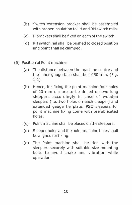
(b) Switch extension bracket shall be assembled
with proper insulation to LH and RH switch rails.
(c) D brackets shall be fixed on each of the switch.
(d) RH switch rail shall be pushed to closed position
and point shall be clamped.
(5) Position of Point machine
(a) The distance between the machine centre and
the inner gauge face shall be 1050 mm. (Fig.
1.1)
(b) Hence, for fixing the point machine four holes
of 20 mm dia are to be drilled on two long
sleepers accordingly in case of wooden
sleepers (i.e. two holes on each sleeper) and
extended gauge tie plate. PSC sleepers for
point machine fixing come with prefabricated
holes.
(c) Point machine shall be placed on the sleepers.
(d) Sleeper holes and the point machine holes shall
be aligned for fixing.
(e) The Point machine shall be tied with the
sleepers securely with suitable size mounting
bolts to avoid shake and vibration while
operation.

11
(6) Connection of throw rod
(a) The machine shall be hand cranked to operate
the drive bar to the centre position. Switch rails
also to be kept in centre position.
(b) The jaw end of throw rod shall be connected to
the gear rack/throw bar of the point machine.
Threaded end of the throw rod shall be guided
through sleeve and the drive lug provided on
the leading William stretcher bar. Nuts and lock
nuts shall be provided on both sides of the
sleeve.
107. Important items of Joint inspection of points
and crossing by SSE/SIG and SSE/Pway :
(1) Condition of Tongue/Switch rail shall be observed for
chipped or cracked over 200 mm length within
1000mm from ATS or twisted or bent (causing gap of
5 mm or more at toe).
(2) Condition and adequacy of fittings upto the heel of
switch (stud bolts, slide chair, plate screw) to be
ensured.
(3) Adequate housing of switch rail with stock rail from
ATS (for 1:8.5 - 3 sleepers and 1:12 -4 sleepers)
shall be checked (Fig.1.1). Burr if any on
stock/tongue rail obstructing the housing of switch
need to be checked.
12
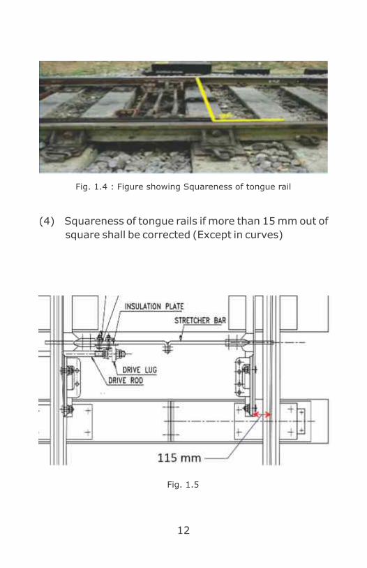
(4) Squareness of tongue rails if more than 15 mm out of
square shall be corrected (Except in curves)
Fig. 1.5
Fig. 1.4 : Figure showing Squareness of tongue rail
13
(5) Throw of Switch: Minimum opening of switch at toe
115 mm (Normal Switch) 160 mm (Thick Webbed
switch)
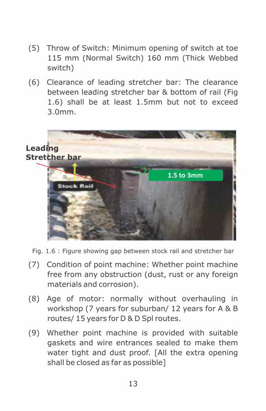
(6) Clearance of leading stretcher bar: The clearance
between leading stretcher bar & bottom of rail (Fig
1.6) shall be at least 1.5mm but not to exceed
3.0mm.
Fig. 1.6 : Figure showing gap between stock rail and stretcher bar
(7) Condition of point machine: Whether point machine
free from any obstruction (dust, rust or any foreign
materials and corrosion).
(8) Age of motor: normally without overhauling in
workshop (7 years for suburban/ 12 years for A & B
routes/ 15 years for D & D Spl routes.
(9) Whether point machine is provided with suitable
gaskets and wire entrances sealed to make them
water tight and dust proof. [All the extra opening
shall be closed as far as possible]
1.5 to 3mm
Leading Stretcher bar

14
(10) Whether motor commutator is clear and free from
carbon deposits (Fig.1.7).
Fig. 1.7 : Figure showing Armature of point machine
(11) Whether point motor insulation and switch bracket
insulation is proper.
(12) Operation of point machine: Whether any unusual
noise observed while operating.
(13) Stroke of the point machine shall be 143mm for IRS
/Siemens, 220mm for IRS clamp type and shall be
checked by measuring the distance covered by
driving rod during point operation.
(14) Operating current shall be measured. 1.2 – 1.5 A for
IRS/Siemens and for thick web switch machine 4.3A
for IRS clamp type (Ref. para 903 (2) of this book for
details)
(15) Obstruction test by 5mm test piece at 150mm from
ATS (Ref. para 903 (1) of this book for further
details)

15
Fig. 8
(16) Slipping current: Upper limit shall not be more than
1.5 to 2 times of normal working current & Lower
limit 0.5 A less than normal working current. (If the
difference between normal operating current and
current under obstruction is less than 0.5 A, machine
shall be replaced).
(17) Condition of rodding including ground connections:
Any play if experienced in pull rod while operating
and also shall be observed if any heel mark is
available.
(18) Clearance of driving rod from rail bottom shall be
25mm to 40mm.
(19) If excess corrosion of ground connection is noticed,
the same shall be renewed.
(20) Fitting of rod arrangements shall be intact.
(21) Lead wires/Signal bonding shall be free from rail,
sleeper and ballast etc.

16
(22) Condition of insulation joints at track circuited points
(Glued joint/block joints) shall be observed.
(23) Condition of insulation joints at Gauge tie plate,
stretcher bar etc.
(24) All bolts and nuts at connections at stretcher bar /
extension pieces shall be intact.

17
CHAPTER 2
Definitions
Some important and often used terms are defined as
follows:
201. Adequate distance :
Any distance sufficient to ensure safety is called an
adequate distance.
202. Aspect of a signal :
This is the physical appearance of a signal as seen by the
Loco pilot of an approaching train.
203. Authority to proceed :
"Authority to proceed" means the authority given to the
Loco pilot of a train ,under the system of working, to enter
the block section with his train;
204. Axle Counter :
"Axle counter" means an electrical device which, when
provided at two given points on the track, proves by
counting axle in and counting axles out, whether the
section of the track between the said two points is clear or
occupied;
205. Block Section :
“Block section " means that portion of the running line
between two block stations onto which no running train
may enter until Line Clear has been received from the
block station at the other end of the block section;

18
206. Facing and trailing points :
"Facing and trailing points": points are facing or trailing in
accordance with the direction a train or vehicle moves
over them. Points are said to be facing points when by
their operation a train approaching them can be directly
diverted from the line upon which it is running;
207. Fixed Signal :
"Fixed signal" means a signal of fixed location indicating a
condition affecting the movement of the train and
includes a semaphore arm or disc or fixed light for use by
day and fixed light for use by night;
208. Indication of a signal :
The meaning conveyed by the signal aspect is called the
indication of the signal.
209. Intermediate Block Post :
"Intermediate Block Post" means a class 'C' station on a
double line, remotely controlled from the block station in
rear;
210. Interlocking :
An arrangement of signals, points and other appliances,
operated from a panel or lever frame, so interconnected
by mechanical locking, or electrical locking or electronic
locking or a combination of these that their operation
must take place in proper sequence to ensure safety.
211. Intermediate Block Signaling :
"Intermediate Block Signaling" means an arrangement of
signaling on double line in which a long block section is
split into two portions each constituting a separate block
section by providing an Intermediate Block Post;

19
212. Isolation :
"Isolation" means an arrangement, secured by the setting
of points or other approved means, to protect the line so
isolated from the danger of obstruction from other
connected line or lines;
213. Last Stop Signal :
"Last Stop signal" means the fixed Stop signal of a station
controlling the entry of trains into the next block section ;
214. Line Clear :
"Line Clear" means the permission given from a block
station in rear for a train to leave the latter and approach
the former; or the permission obtained by a block station
from block station in advance for a train to leave the
former and proceed towards the latter;
215. Multiple-aspect signaling :
"Multiple-aspect signaling" means a signaling
arrangement in which signals display at any one time any
one of the three or more aspect and in which the aspect of
every signal is pre-warned by the aspect of the previous
signal or signals;
216. ‘ON’ aspect :
The most restrictive aspect of a signal is called the “ON”
aspect of the signal.
217. OFF aspect :
Any aspect of signal other than its “ON” aspect is called its
“OFF” aspect.
218. Overlap :
The length of track that is required to be kept clear beyond

20
a stop signal before a stop signal in rear can be taken
“OFF”, is called an overlap.
219. Station limits :
"Station limits" means the portion of a railway which is
under the control of a Station Master and is situated
between the outermost signals of the station or as may be
specified by special instructions.
220. System of working :
"System of working” means the system adopted for the
time being for the working of trains on any portion of a
railway.
221. Track circuit :
"Track circuit" means an electrical circuit provided to
detect the presence of vehicle on a portion track, the rails
of the track forming part of the circuit.

21
CHAPTER 3
Types of Signals
Signals are classified, depending on the type of
movement they control, their method of working, etc. The
following are the different types of signals
(1) Fixed signals,
(2) Hand signals,
(3) Detonating signals, and
(4) Flare signals.
301. Fixed Signals :
Fixed signals are the most commonly used signals and are
provided at fixed locations by the side of the track. These
signals are used for receiving or dispatching a train or for
shunting at stations. In between stations, signals are
provided to keep a safe distance between two trains.
Based on the type of movement they control, fixed signals
are classified as
(1) Main or Running Signals,
(2) Subsidiary Signal

22
Further signals can be
Ÿ Semaphore (Fig.3.1 & 3.2)
Ÿ Colour light (Fig.3.3)
Main signals govern the movement of running trains while
shunt signals are one of the subsidiary signal govern the
movement of trains while shunting (attachment or
detachment of locomotives coaches or wagons at
station). Main signals can be of two types:
Ÿ Permissive signals
Ÿ Stop Signals
Permissive signals may be passed even in the “ON”
position, though at restricted speed and after observing
some precautions. Stop Signals when “ON” must not be
passed by the Loco Pilot without a written authority.
However, in case of certain Stop signals, Loco Pilot can
pass following Signals at danger after observing
prescribed precaution, are:
(a) Gate Stop Signal
(b) Automatic Signals
(c) Intermediate Block Signal

23
302. Semaphore Main signals :
Fig. 3.1
303. Semaphore Permissive signals :
Fig. 3.2
304. Colour Light signals (CLS) :
Fig. 3.3

24
Colour Light Signals (Fig.3.3) consist of two or more
different colour light mounted vertically, one over the
other. Each consists basically of a bulb, and a focusing
lens arrangement. The lens focuses the light into a
powerful beam, to give good visibility during day as well
as night. One bulb is provided for each aspect of the
signal. Thus by choosing appropriate colors, two three, or
more aspects can be provided. In India presently 2, 3 and
4 aspect signals have been provided though some
countries use more than 4 aspects. The colors used are
red, yellow and green. The fourth aspect used is “double
yellow” when two yellow lights are displayed. Now a days
LED signals are introduced in lieu of conventional lamps.
305. Aspect and indication :
The aspect of a signal means its physical appearance. For
example, a semaphore lower quadrant signal has two
aspects – “ON” when the signal arm is horizontal, and 0“OFF” when the arm is lowered (45 ). It means that the
aspect conveys is its indication. In this case, “ON”
indicates Stop, while “OFF” indicates Proceed. A
semaphore Multiple Aspect Upper Quadrant (MAUQ)
signal can have three aspects. Such stop signals have an
“ON” aspect indicating Stop, a caution aspect with the 0arm raised by 45 . indicating Proceed cautiously and be
prepared to stop at the next signal and a clear aspect it 0the arm raised to 90 . Indicating Proceed at The Maximum
Permissible Speed (Fig.3.1).
306. Two Aspect & Multiple Aspect Signalling :
A signal must have at least two aspects to convey any
meaning to the Loco Pilot. A two aspect stop signal can

25
indicate to the Loco Pilot to either proceed or stop. As may
be seen, in such a system, the Loco Pilot can only be given
information about that particular signal. it is advisable to
give advance warning to the Loco Pilot about aspect of the
next signal. This needed a third aspect, which can be
provided with MAUQ or MACL signaling.
Multiple Aspect signaling enables advance warning being
given to the Loco Pilot of the aspect of the next stop
signal. A Loco Pilot is fore-warned and thus can able to
control train more confidently to improve safety. When 3
or 4 aspect colour light signaling (Fig.3.3) is used, it is
collectively called Multiple Aspect Color Light Signals
(MACLS).
307. Kind of Signals and their Locations :
As mentioned earlier, signals can be divided into
Reception and Departure Signals. Reception signals
govern the reception of a train at a station. Generally,
signals placed on the left of the track to which they
pertain. In certain cases, signals can be placed on right
hand side with special instruction by Authorized officer.
In Multiple Aspect Signaling, the Distant Signal
(Permissive Signal) is the first signal at a station. Its
normal aspect is "yellow", when the Home signal (first
stop signal) is at “ON or Danger”. The Distant Signal
assumes an “OFF/Clear” aspect when the Home signal is
“OFF/Clear”. The Distant Signal thus pre-warns the Loco
Pilot of the aspect of the Home Signal. The Departure
Signals are the Starter and the Advanced Starter Signals
(Last Stop Signal). The Starter is placed at the end of the

26

27
berthing line, in rear of the points. The Advanced Starter
is the last Departure Signal and is placed outside all
connections. It is the authority to proceed to the next
station and is therefore taken “OFF” after “Line Clear” is
obtained from the next station. The advanced starter is
placed at not less than 120 meters from the outermost
points.
308. Signal and Block Overlaps :
There are two types of overlaps, Signal Overlap and Block
Overlap.
(1) Signal Overlap
The length of track in advance of a stop signal, which
should be kept clear before the signal next in rear
can be taken 'OFF' is known as the signal overlap.
Fig. 3.4
In Fig 3.4, Sig 1 can be taken “OFF” only after not
only the inter signal distance, but also the overlap
beyond Sig 2 is clear. This distance is based on
speeds and the type of signaling on the section. It
has been mentioned earlier, that in multiple aspect
territories, a Stop signal is pre-warned. Hence, it is
evident that the Loco Pilot is better able to control his
train, thus reducing the margin for error. Hence
overlaps can be reduced with pre-warning. Signal
overlap shall be not less than 120 mts from the
starter signal.

28
(2) Block Overlap:
For the last stop signal of a station, the overlap is
required to be kept beyond the first stop signal of the
next station. This is called the Block overlap (Fig.
3.5). In view of the higher speeds of trains when
running between stations, the block overlap is
greater than the signal overlap.
The block overlap shall not be less than 180 meters
measured from home signal.
Fig. 3.5
309. Subsidiary Signals :
In addition to the running signals, subsidiary signals are
used for inter-yard movements such as attaching or
detaching of wagons/engines, marshaling in which speed
of the movement are low and confined to a small area and
the line on which the movement is to be done may
invariably be occupied by vehicles and as such the Loco
Pilot has to exercise more caution. Moreover, as the
movement is done in a smaller area, the visibility of the
signal is not critical and low visibility is adequate. Also no
pre-warning is necessary. Since visibility required is less,
smaller types of signals can be used compared to running
signals.

29
310. Shunt Signals :
A shunt signal is placed either on a post by itself, or below
a main signal on the same post. A shunt signal below a
stop signal does not exhibit any light in the “ON” (Normal)
position.
Fig. 3.6 Fig. 3.7
A position light shunt signal (Fig.3.6) is used in colour
light signaling territories and exhibits two horizontal white
lights in the “ON” position, and two inclined white lights in
the “OFF” (Clear Aspect) position. No light is shown in the
“ON” position, when placed below a stop signal (Fig. 3.7).
311. Repeating Signals :
When the distance at which a signal can be sighted is
inadequate, another signal is provided at a location in rear
of the main signal to repeat the aspect of the main signal.
This is called a repeating signal (Fig.3.8).
A repeating signal is provided with an “R” marker, and is
treated as permissive signal.

30
312. Calling – On Signals :
Fig. 3.9
A calling-on signal (Fig.3.9) is a subsidiary signal and is
provided below a stop signal (except Advanced Starter
Signal). When “OFF”, it permits a Loco Pilot to draw past
the concerned stop signal at “ON”, after the train has been
brought to a stop. The Loco Pilot is required to proceed
with caution, and be prepared to stop short of any
obstruction. Calling-on signals are generally provided at
important stations where track circuiting is provided, to
Fig. 3.8

31
draw a train ahead, when failure of the track circuit results
in failure of the main signal, though the route has been
correctly set. A calling - on signal does not show any light
in the “ON” position.
313. Gate Signals :
Gate signals are provided to protect level crossing gates.
These signals are provided at an adequate distance from
the gate, and are provided with “G” markers (Fig.3.10).
The marker consists of the letter “G” on a yellow circular
disc.
314. Automatic Signals :
Automatic signals (Fig.3.11) operate automatically by the
passage of trains. The track needs to be provided with
continuous track circuiting, or axle counters. As the train
proceeds, the occupation and clearance of the track is
detected and causes the aspects to changes automatically.
Automatic signals are provided with “A” markers.
Automatic signals are provided under Automatic Block
system working only.
Fig.3.11Fig.3.10 Fig.3.12

32
315. Intermediate Block Signals :
In Absolute block system, to split a lengthy block section
into two parts, Intermediate Block (IB) Signals are
provided. (Fig.3.12)
316. Operation of Signals :
Signals can be operated manually, or automatically and
are called Manual or Automatic signals accordingly.
Manual signals are operated by:
(1) Lever, or
(2) Panels.
Levers are used in semaphore as well as colour light
signaling system. The signals are connected to the
Lever Panel
Fig. 3.13
levers by wires, or are operated electrically through
cables. The levers are generally grouped together in
special frames called level frames. These lever frames are
used to provide interlocking between lever operating
points, signals etc. Panels consist of groups of switches
which actuate relays for controlling operation of points
and signals. In this, interlocking between Signals, point,
track circuit etc. are achieved by relays. Hence such
arrangement is called relay interlocking.

33
317. Operations of Points :
Points are used to divert trains from one line to the other.
Their proper operation and correct setting is thus a vital
safety requirement. Points are worked by:
(1) Rodding, or
(2) Double wire, or
(3) Electric point machines.
The two switches of a point are coupled together by at
least two flexible stretcher bars. One or more of these
stretcher bars are connected to the operating
mechanism.
318. Locking of Points :
To ensure safe running of trains, it is essential that a point
is locked so that its position cannot be disturbed when a
train is moving over it in the facing direction.
In rod operated points, a separate facing plunger lock
(FPL) is provided for all points where movement is made
in the facing direction. Each of the switches of a point is
connected to a stretcher bar with notches cut in them.
When the lock lever is operated, a plunger enters the
notches and physically locks the switches. Where electric
Mechanical
Fig. 3.14
Point of Machine Operated

34
point machines are provided, the locking of the stretcher
bars is done in the point machines.
319. Detection of Points :
For safety of train running, it is necessary to check
whether the points are set correctly, before movement is
made over them. It is necessary to not only check that the
point in the required normal (N) or reverse (R) position,
but also check whether the closed switch is set against the
stock rail without any gap, and the gap between the open
switch and the stock rail is sufficient. This needs to be
done before the concerned signal can be taken “OFF”. This
is called detection of a point.
Detection can be done either:
(1) Mechanically, or
(2) Electrically.
Mechanical detection is done in the case of rod operated
points. In a typical arrangement, each of the switches is
connected via rods to a slide. These slide move transverse
to the track when the point is operated. The slide has
notches cut in them through which another slide can
operate only if the switches are properly set. This slide
gets obstructed if either of the switches is not properly
set. This slide is connected in the signal clearing circuit
and thus prevents the clearing of the signal if any of the
switches is not correctly set. In electric detection, the
switches are connected to electrical contacts, which close
only if the switches are correctly set. Motor operated
points as well as double wire operated points and provided
with electric detection.

35
In view of the tight tolerances, it is essential that:
(a) The gauge at the switches be exact,
(b) Switches provided be in good condition and
that the switch ends are not damaged,
(c) Switches have equal spring in both settings,
(d) Switches are periodically lubricated.

36
CHAPTER 4
S & T Cable - Laying & Precautions
On Indian railways, there is a vast network of cable laid for
Signal & Telecommunication and Power Transmission.
Now a day’s, lot of improvement work like gauge
conversion, doubling, automatic block signaling, laying of
OFC, Electrification etc. are in full swing. During execution
of such work, cable cut/damage is more prominent & lead
to lot of detention, delay & may develop unsafe condition
for railway working. For such new projects, cable laying
work is also an important targeted work. There is a need
to address the cable laying planning as well as
precautions while digging work in the vicinity of cables.
This chapter compiles available instructions in this regard
for awareness of respective departments to avoid unusual
incidents & unsafe conditions.
It covers planning, cable laying practices and precautions
to be adopted before and during execution of Engineering
works near vicinity of S&T cables.
401. Planning of cable laying: (IRSEM Chapter XV &
RDSO Guidelines on cable laying)
It is recommended that new cable route plan should be
prepared after on-foot survey of the proposed cable
laying site. Cable route plan must clearly show actual
alignment of track giving offsets from permanent way or
permanent structures. In addition to this, the diagram
should indicate the various roads and track crossings,
crossing with power cables, water and sewage mains and
other point of importance. Work like future expansion of

37
yard, yard modification, doubling, gauge conversion etc
should also be considered while preparing cable route
plan. If possible, low laying areas, platform copings,
drainages, hutments, rocky terrains, points and
crossings, should be avoided. Cable route plan should be
approved by Engineering, S&T and Electrical Department.
(IRSEM Para 15.3.6)
Cable should not be laid above ground level, only in
exceptional cases where it is impossible to lay
underground, in such case, cable should be laid in
following manners.
l The cable should be suspended in steel cleats,
from cable hangers or in any other approved
manner so that no mechanical damage occurs to
the cable even under exposed condition. In
station yards, cable should be laid in ducts
suitably protected.
l The cable supports should be so spaced as to
avoid sag.
In Electrified sections, cables should be laid underground
only. For laying cables in RE area, the following
instructions laid down in Signal Engineering Manual shall
be followed.
(1) Cables may be laid underground, either in the
trench, in ducts, in cement troughs, in pipes or
in any other approved manner.
(2) For carry ing s ignal l ing c i rcui ts, PVC
(Polymerization of Vinyl Chloride) insulated,
PVC sheathed and armoured unscreened cable

38
RD
SO
/SI/
G/2
010 D
t.04.0
2.2
014 A
nnexure
.05
Fig. - 4.1

39
to an approved specification (IRS-63) should
be used. Further, approved type (IS-1554)
power cable should be used for signalling
purposes.
402. Position of trenches for cable laying :
Position of trenches for cable laying depending upon the
location of cable whether it is laid in station limit, or
outside station limit, near OHE structures, during track
crossing, near bridges/culverts, arch & steel bridges. The
work should be carried out as under:
Ÿ Position of cable trench while track on formation
(outside/inside station limit) (Fig.4.1)
Ÿ Position of cable trench while track crossing.
(Fig.4.3 & 4.4))
Ÿ Cable laying in larger yard & suburban area.
Ÿ Cable laying in rocky area (Fig.4.5)
Ÿ Cable laying on bridges. (Fig.4.6- 4.10)
(1) Position of cable trench while track on formation
(outside/inside station limit)
When cables are laid outside the station limits, the
cables should be laid at not less than 5.5 metre from
the centre of the nearest track. (fig.4.1) (IRSEM Para
15.16 (9))
When cables are laid within the station limits, the
trenches should be dug at a distance of not less than
3 metre from the centre of the track, width of the
trench being outside the 3 metre distance. (IRSEM
Para 15.16 (ii))
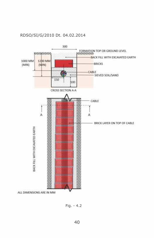
40
Fig. - 4.2
RDSO/SI/G/2010 Dt. 04.02.2014

41
At each end of the main cable an extra loop length of 6 to 8
metre should be kept. Extra loop length of the cable
should also be buried at same depth and trench as that of
cable in the and not projected outside to ensure that
cable is free from theft/outside interference. Before
starting cabling work, location boxes should first be
erected so that cable after laying is directly taken inside
location box and its multiple handling/damage by re-
digging and taking inside location box/Relay Room is
eliminated.
(2) Position of Cable laying while Track crossing (Fig.
4.3)
If possible, it should be ensured that cable should be
crossed at two locations, i.e. one crossing on each
side of the yard.
When a cable has to cross the track, it should be
ensured that-
(a) Cable should cross track at right angles; The
cable should not cross the track below points
and crossings and it should be laid in
concrete/GI (Galvanized Iron)/CI (Cast
Iron)/PVC/DWC (Double Wall Corrugated)-
HDPE pipes or suitable ducts or in any other
approved manner while crossing the track.
(b) The depth of cable laid across the track must be
1.0 metre (minimum) below the rail flanges. No
digging should be done below the sleepers.
Digging work while crossing a track should be
done between sleepers in the presence of a
Railways representative. (IRSEM Para 15.12)

42
(c) The cable laid parallel to the track should be
buried at a depth of minimum 1.0 metre (top
most cable) from ground level.
Fig. - 4.3
Tra
ck C
rossin
g
RDSO/SI/G/2010 Dt. 04.02.2014 Annexure. 12

43
(d) The width of manually made cable trenches
should commensurate with number of cables.
The minimum width should be kept as 0.3
meters. The bottom of the cable trench should
be levelled and get rid of any sharp materials.
In the soft ground, the cable should be laid at
the bottom of the trench previously levelled. In
the rocky ground, the cable should be laid on a
layer of sand or sifted earth of 0.05 metre
thickness previously deposited at the bottom of
the trench. In both the above cases, the cable
should be covered with a layer of sand or sifted
earth of 0.10 metre thickness and thereafter a
protective cover of trough or a layer of bricks
should be placed.
(e) In places where cables are to be laid within 1
metre from sleeper end, digging beyond 0.50
metre should be done in the presence of an
official from Engineering Department, and the
laying of the cable and refilling of trench should
be done with least delay. Laying may be
undertaken under block protection as needed.
(f) Normally, not more than 12 cable are to be laid
in one trench as it would be difficult to attend
failure at a later date. At a moderate size
station with electrical signaling installation,
generally the numbers of cable are more up to
home Signal, it is recommended that cables are
laid in RCC duct up to home signal on both side
of the station and may be extended up to
44
Fig. - 4.4
RDSO/SI/G/2010 Dt.04.02.2014 Annexure. 20
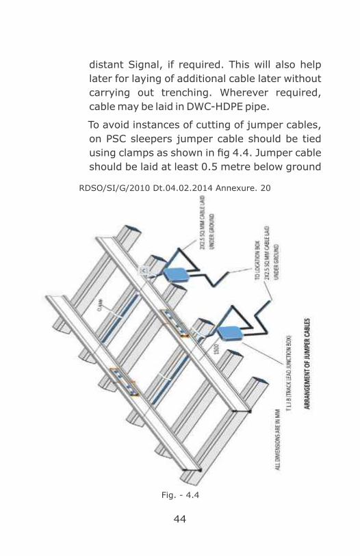
distant Signal, if required. This will also help
later for laying of additional cable later without
carrying out trenching. Wherever required,
cable may be laid in DWC-HDPE pipe.
To avoid instances of cutting of jumper cables,
on PSC sleepers jumper cable should be tied
using clamps as shown in fig 4.4. Jumper cable
should be laid at least 0.5 metre below ground

45
level excluding ballast depth. Jumper cable
should be laid neatly in squared manner and
should not be kept in loose coils above the
ground near TLJB (Track lead Junction Box).
Top surface of TLJB should not be more than 1
foot above rail level.
(3) Position of Cable trenches in large yard and suburban
area
( G u i d e l i n e s f o r s i g n a l i n g c a b l e l a y i n g
RDSO/SI/G/2010 Dt.04.02.2014)
Main signalling cables in large yards including
suburban section should be laid in RCC ducts/DWC-
HDPE pipes. Tail cables should be laid through DWC-
HDPE pipes of suitable sizes and buried in trenches at
a depth of not less than 1000 mm from ground level.
Approved types of ducts may be used for laying of
cable, following norms to be followed.
(a) RCC, masonry or any other approved type of
ducts may be used for laying the cable. The
ducts should have suitable covers and should
rest on walls of duct. The ducts should be of
such design as to prevent water collecting in
the duct. In RCC ducts, it is recommended to
have height of maximum 300 mm (outside
dimension inclusive of removable top cover).
Length of the duct should be between 700 mm
to 1000 mm (outside dimension). This is
mainly required for easy transport of ducts
from factory premises to the work sites. Depth
of 600 mm to 1000 mm is recommended

46
according to requirement of Zonal Railways
depending on site condition. For jointing ends
of RCC ducts precaution should be taken for
proper alignment of RCC ducts, so that gap
between two ducts is kept minimum.
(b) When cables are laid in rocky area, it is
desirable to protect them with split RCC ducts
of suitable design.
(c) Where it is necessary to take the cable between
the tracks, it should be carried in trunking kept
sufficiently below the ballast level.
(d) Cables for longer distances should be laid on
bottom layer. Duct should be filled up with sand
after cable is laid to avoid entry of rodents.
(e) From Up Home to Down Home Signal, where
number of signalling cables required are more,
subject to availability of space adjacent to
tracks, RCC ducts with removable top cover
with larger width up to 500 mm are
recommended.
(f) Beyond Home Signal and up to distant signal
including block section/ automatic section RCC
ducts with a width up to 300 mm are
recommended.
(4) Precautions for cable laying in the vicinity of OHE
Structure (RDSO Guidelines For Signalling Cable
Laying RDSO/SI/G/2010 Dt.04.02.2014):
(a) The cable should be so laid that it is not less
than one meter from the nearest edge of the

47
mast supporting the catenary or any other live
conductor, provided the depth of the cable does
not exceed 0.5meters. When the cable is laid at
a depth greater than 0.5 meters, a minimum
distance of 3 meters between the cable and the
nearest edge of the O.H.E structure should be
maintained. If it is difficult to maintain these
distances, the cable should be laid in concrete /
heavy duty HDPE (High Density Polyethylene)
/Ducts or any other approved means for a
distance of 3 meters on either side of the Mast.
When so laid, the distance between the cable
and the mast may be reduced to 0.5 meters.
These precautions are necessary to avoid
damage to the cable in the event of the failure
of an overhead insulator.
(b) In the vicinity of traction sub stations and
feeding posts, the cable should be at least one
metre away from any metallic part of the O.H.E
and other equipment at the sub- station, which
is fixed on the ground, and at least one metre
away from the substation earthling. In
addition, the cable should be laid in concrete or
heavy-duty HDPE pipes/ Split RCC pipes or
other approved means for a length of 300
meters on either side of the feeding point. As
far as possible, the cable should be laid on the
side of the track opposite to the feeding post. In
the vicinity of the switching stations, the cable
should be laid at least one metre away from any
metallic body of the station, which is fixed in

48
the ground, and at least 5 meters away from
the station Earthing. The distance of 5 meters
can be reduced to one metre provided the
cables are laid in concrete pipes/heavy-duty
HDPE pipes /ducts or any other approved
means. Where an independent Earth is
provided for an OHE structure, i.e. where the
mast is connected to a separate Earth instead
of being connected to the rail, the cables should
be laid at least one metre away from the Earth.
(c) Where there are O.H.E structures along the
cable route, the cable trenches should as far as
possible, be dug not less than 5.5 meters away
from the centre of the Track.
(d) Cable is generally laid parallel to the track
beyond Home signal with minimum deviations
and on one side of the yard.
(5) Position Cable trench in Rocky Soil
In case of rocky soil, the depth may be reduced
suitably. When it concerns the laying of tail cables
which serve the track apparatus etc. the depth
should not be less than 0.50 metres. In theft prone
areas the cables may be laid at a depth of 1.2 metres
with anchoring at every 10 metres. Sharp edges on
the sides must be smoothened out and bottom of the
chase should be leveled. In the rocky ground the
cable should be laid normally on layer of sifted earth
of 0.05 metres thickness previously deposited at the
bottom of the trench. Cable should be covered with
the layer of sand or sifted earth of 0.1 metre
thickness.

49
In case sharp edge of rocky ground cannot be
protected with sifted earth, concrete/GI/CI/
PVC/DWC-HDPE pipe should be used if number
RDSO/SI/G/2010 Dt.04.02.2014
Fig. - 4.5

50
of cables are small. If number of cables are
large, RCC duct should be used. In isolated
cases, it can be given smooth surface by using
either masonry bricks or cement concrete.
A row of bricks should then be placed
lengthwise on the top and jointed with cement
mortar and a layer of concrete with cement
plaster should be provided on the top of the
same.
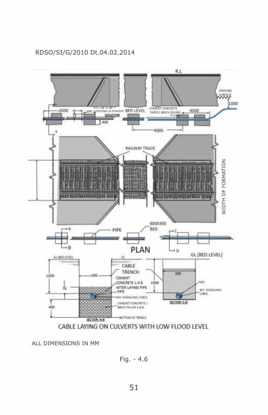
(6) Position of Cable trench on bridges/culverts:
Wherever practical, the cable may be taken
underground across the drain bed at a suitable
depth for crossing small culverts with low flood level.
51
RDSO/SI/G/2010 Dt.04.02.2014
Fig. - 4.6
WID
TH
OF F
ORM
ATIO
N
ALL DIMENSIONS IN MM

52
Where cable may not be taken underground across
the drain bed, cable should be taken on the culvert
through GI/DWC-HDPE pipe of suitable sizes.
When cables have to cross a metallic bridge, they
should be placed inside a metallic trough which may be
filled, as an anti-theft measure, with sealing compound.
The cable should be supported across the bridge in a
manner which would involve minimum vibrations to the
cable and which will facilitate maintenance work.
Adequate cable length to the extent of 2 to 3 meters
should be made available at the approaches of bridge.
RDSO/SI/G/2010 Dt.04.02.2014
Cable Laying in Culvert with High Flood Level
All dimensions are in MM
Fig. - 4.7

53
In case of arch bridges, cable should be taken
through GI/DWC-HDPE pipes on top of the arch adjoining
the parapet wall. The pipe should be covered with ballast.
Concreting of 50 mm should be done throughout
from entry/exit end of cable up to diversion point
including slope on either side. The entry and exit ends of
the cable from the pipe to the diversion point of the cable
should be concreted for 1 metre (minimum).
RDSO/SI/G/2010 Dt.04.02.2014
Cable Laying in Metallic Bridges
All dimensions are in MM
Fig. - 4.8

54
As the laying involves movement of a large number of
staff over the bridge the line should be blocked and
flagman posted on either side. On a double line only the
line near where the cable is being laid should be blocked
but care should be taken to see that staff are aware of this
and measures taken to prevent staff from straying on to
the unblocked line.
Damage to cable is likely to occur if care is not taken in
cable laying where the bed changes from solid support
Cable Laying in Arch Bridges
Fig. - 4.9

55
such as a foundation, pier of bridge to soft support such as
soft soil. The cable must not press against the edge of the
solid support. The soft soil near the edge must be tamped
and the cable raised slightly.
In order to prevent theft and miscreant activities on
approach of cable to bridge/culvert where it is not
possible to ensure adequate depth, concrete protection is
proposed.
RDSO/SI/G/2010 Dt.04.02.2014 Annexure.19
Fig. - 4.10
Brick Masonry Channel for Arch Bridge
56
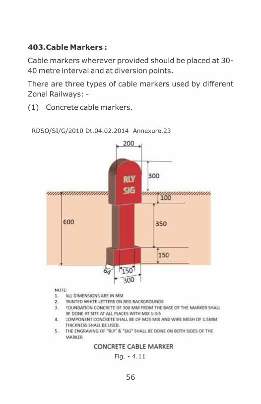
403. Cable Markers :
Cable markers wherever provided should be placed at 30-
40 metre interval and at diversion points.
There are three types of cable markers used by different
Zonal Railways: -
(1) Concrete cable markers.
RDSO/SI/G/2010 Dt.04.02.2014 Annexure.23
Fig. - 4.11

57
(2) Cast iron Tablet type cable markers.
404. Precautions During Digging Work Near
Vicinity of Cables : (RB letter no.2004/SIG/G/7
Dt.17.12.2004 JPO no.1/Sig/2004)
The following procedure should be followed by concerned
department(s) while carrying out any digging work near
to existing signalling & telecommunication and electrical
cables, so that the instances of cable cut due to execution
of works can be controlled and minimized.
(1) S&T Department (and RailTel, where they have laid
the cables) & Electrical Deptts. should provide a
detailed cable route plan showing exact location of
cable at an interval of 200m or wherever there is
change in alignment so that the same is located
easily by the Engineering official/contractor.
RDSO/SI/G/2010 Dt.04.02.2014 Annexure.21 & 22
Fig. - 4.12
All Dimensions are in MM

58
(2) They should also provide cable markers wherever
digging/earth work is undertaken by engineering
department.
(3) This cable route plans should be made available to
the concerned Divisional/Construction officers as
the case may be by Divisional officers of S&T or
Electrical Department or Construction organization
within a reasonable time in duplicate.
(4) Divisional/Construction Engineering officers will
send copies to their field unit.
(5) Before taking up any digging activity on a particular
work by any agency, Divisional officers of S&T or
Electrical Department of the section should be
approached in writing by the concerned Engg or S& T
or Electrical officer for permitting to undertake the
work.
(6) After ensuring that the concerned executing
agencies including the contractor have fully
understood the S&T and Electrical cable route plan
should permit the work in writing.
(7) After obtaining permission from S&T or Electrical
Deptt. as the case may be, the relevant portion of
the cable route plan should be attached to the letter
through which permission is issued to the contractor
by concerned Engg. official for commencement of
work and ensuring that the contractors have fully
understood the cable route plan and precautions to
be taken to prevent damage to the underground
cables. The contractor should be asked to study the
cable plan and follow it accurately to ensure that the

59
safety of the cable is not endangered unless any
penalty for default, should form part of agreement
also. However basic responsibility will be of the
Department executing the work and the Contractor.
(8) The Field Engineering officials should pass on the
information to the concerned field S&T or Electrical
Engineers about the works being taken up by the
contractors in their sections at least 3 days in
advance of the day of the work. In addition,
Engineering control should also be informed by the
Field Engineering officials, which in turn should pass
on the information to the Test Room/Network
Operation Centre of RailTel/TPC/Electrical Control.
(9) On receiving the above information, SSE (Sig) or
SSE (Tele) or SSE (Elect.) should visit the site on or
before the date of taking up the work and issue
permission to the contractor to commence the work
after checking that adequate precautions have been
taken to avoid the damage to the cables. The
permission should be granted within 3 days of
submission of such requests.
(10) The name of the contractor, his contact 'telephone
number, the nature of the work should be notified in
the Engineering Control as soon as the concerned
Engg. official issued the letter authorizing
commencement of work to the contractor. Test Room
to be given a copy and should collect any further
details from the Engineering Control and should pass
it on to S&T/RailTel & Elect. officials regularly.

60
(11) In case of works being taken up by the State
Government, National Highway Authority etc., the
details of the permission given i.e. the nature of
work, kilometer etc. be given to the Engineering
Control including the contact person's number so
that the work can be done in a planned manner. The
permission letter should indicate the contact
numbers of Test Room/Network Operations Centre
of RaiITeI/TPC/Elect. Control.
(12) Where the nature of the work taken up by the
Engineering department is such that the OFC or
other S&T cables or Electrical cables is to be shifted
and relocated, notice of minimum one week should
be given so that the Division/RailTel/Construction
can plan the works properly for shifting. Such
shifting works, for security and integrity of the
cables, be supervised by S&T / RailTel / Electrical
Officials.
(13) SSE (P. Way)/(Works), SSE(Sig)/(Tele), SSE(Elect.)
or RailTel officials, supervising the work of the
contractor should ensure that the existing
emergency sockets are not damaged in view of their
importance in providing communication during
accident/emergency.
(14) In case of minor nature of works where shifting of
cable is not required, in order to prevent damage to
the cable, the Engineering Contractor should take
out the S&T or optical fiber cable or Electrical cable
carefully from the trench and place it properly
alongside at a safe location before starting the
61
earthwork under the supervision of SSE (Sig)/ (Tele)
or SSE (Electrical). The cable should be reburied
soon after completion of excavation with proper care
including placement of the brick over the cable by
the concerned S&T or Electrical officials. However,
the work will be charged to the concerned
engineering work.
(15) In all the sections where major projects are to be
taken up/going on RailTel/S&T Deptt. should deploy
their official to take preventive /corrective action at
site of work.
(16) No new OFC or quad cable should be laid close to the
existing track. It should be laid close to the railway
boundary to the extent possible to avoid any
interference with the future works (doubling etc.). It
should be ensured in the new works of cable laying
that the cable route is properly identified with
electronic or concrete markers. Henceforth,
wherever cable laying is planned and before
undertaking the cable laying work, the cable route
plan of the same should be prepared by the
construction organization and should be got
approved from the concerned Divisional S&T or
Electrical officers for all other projects including
doubling, GC etc., to avoid possible damage in
future. Such approval should be granted within
seven days of the submission of the request.
(17) The works of excavating the trench and laying of the
cable should proceed in quick succession, leaving a
minimum time between the two activities.

62
(18) Any damage caused to OFC/Quad cable or Electrical
cable during execution of the work, necessary debit
should be raised on Engineering Department who
should bear the cost of the corrective action.
(19) All types of bonds i.e. rail bond, cross bond and
structure bond should be restored by the Contractor
with a view to keep the rail voltage low to ensure
safety of personnel.
(20) Above instructions are applicable for construction as
well as open line organization of Engineering, S&T &
Electrical.
405. Precaution against fire in the vicinity of
underground S&T/Electrical cables: (RB letter
no.2011/SIG/SF/1/Pt Dt.23.02.2012)
Signalling Cables get burnt due to fire in garbage over
Cable route, dry grass & bushes around relay huts and
also fire under GI pipes carrying Signalling cables at
culverts wherein garbage mixed with waste diesel oil from
yard catch fire.
(1) Earth work in Railway premises should be allowed
only after getting approval of open line ADSTE, AEN
& AEE so that S&T and Electrical cables can be
protected wherever required.
(2) Burning of Garbage should not be allowed in station
yard. 1n case it is unavoidable, burning should be
done in a controlled manner under supervision of
concerned staff after getting clearance of Section ln-
charges from Signal, Telecom & Electrical
department.

63
(3) Garbage should be dumped at identified marked
locations and to be disposed off at regular intervals
by shifting or by burning in a controlled manner
under supervision of concerned staff (Health,
Engineering or Commercial).
(4) Patrolling of station/section by S&T Supervisors,
Technician and Helper/ Khalasi should• be done
along with periodic maintenance and record be
maintained for any unusual things noticed like cable
exposed, fire in vicinity of track, earth work, garbage
around cables etc. and also corrective action taken
thereafter.
(5) Cable cuttings on Bridges are most vulnerable and
therefore cables should be laid in two sets with
sufficient spares, half on up line and balance on
down line. Spare cables on bridge shall be laid and
terminated in location boxes so as to use in
emergency.
(6) Vulnerable locations are identified and time bound
action plan to be made for remedial measures.

64
CHAPTER 5
Block Working and Interlocking
For safety of train working, an interval is kept between
two trains. In earlier times, a time interval was kept
between two trains following each other on the same line.
This system was not considered adequate to ensure
safety when the densities of trains as well as their speeds
increased. The system now followed, uses a space
interval between trains. The entire stretch of a Railway
line is divided into sections, and when a train enters a
section, it is “blocked” for all other trains. Another train is
allowed to enter this section only after the first train has
cleared the section. These section are called Block
sections, and the system of working is called Block
working.
Trains are permitted to enter the block section, after
receiving permission to do so. Stations are provided at the
two ends of a section and are called block stations. These
are provided with signals to control entry in the block
sections. In automatic working, entry to such sections
are controlled by signals which operate automatically by
passage of trains.
To control movement of trains between two block
stations, they are connected by telephones. In addition,
except where train densities are very low, special
instruments are provided between the block stations to
grant permission for a train to proceed from one station to
the other. These instruments are called Block
Instruments.

65
501. Systems of Block Working :
The following systems of block working are followed on
Indian Railways:
l The absolute Block System,
l The automatic Block System,
l The Following Train System,
l The Pilot Guard System,
l The Train-staff and Ticket System, or
l The One Train Only System.
In Indian Railways only the Absolute Block system and the
Automatic Block Systems are in use.
(1) The Absolute Block System
In the Absolute Block System, the line is divided into
sections, with stations at each end of the section.
The stations are called block stations. The portion of
the line between the two block stations is called the
“block section.” Line Clear refers to the permission
given from a block station to the block station in rear
for a train to leave the latter and approach the
former, or the permission received by a station from
a station in advance for a train to leave the former
and proceed towards the latter.
In the absolute Block System no train is allowed to
leave a block station, unless,-
(a) Line clear has been received from the station in
advance, and
(b) On double lines, is clear, not only up to the first
stop signal, at the station giving line clear but
also for an adequate distance beyond it;

66
(c) On single lines, line is clear of trains running in
the same direction, not only up to the first stop
signal at the station giving the line clear, but
also for an adequate distance beyond it, and is
clear of trains running in the direction towards
the block station to which such line clear is
given.
The adequate distances referred to in paras
above, shall not be less than-
(i) 400 meters in the case of two aspect
signaling, and
(ii) 180 meters in the case of multiple-aspect
signaling.
Where train densities are very low, simple means of
communication like Morse telegraph, or telephones,
are considered enough for granting and receiving
line clear. On other sections Block Instruments of
various types are used on the Indian Railways.
On the double line sections, these block instruments
are interlocked with the signals in such a manner
that the last stop signal of the station, which governs
entry into the block section, cannot be taken “OFF”,
unless line clear has been obtained from the station
in advance. A common instrument is used for both
the lines on a double line section. The instruments
are provided with a visual indication that line clear
has been granted or received. When a train enters
the block section, the indication changes to “train on
line” indicating to the station staff, that a train is in
the block section. When the train has cleared the

67
block section, the indication changes to “line close”
indicating that there is no train in the block section.
On single line section, two types of block
instruments are used (Fig.5.1)
Fig. - 5.1
Fig. - 5.2
Neal's Ball Token Block Instrument Token Less Block Instrument
Block Instrument for Single Line

68
The instruments at the adjoining stations are
connected to each other, electrically, and so
interlocked that trains cannot be sent by both
stations towards each other, at the same time.
On Double line section, SGE Double line block
instruments (Fig.5.2) are used.
(2) The Automatic Block System:
On Double Line Sections :-
= The line is required to be provided with
continuous track circuiting or axle counters,
= The line between two block stations is divided into
a series of automatic block signaling sections, the
entry to which is governed by a stop signal,
= The track circuit or axle counter so controls the
stop signals governing entry into an automatic
block section that the signal does not assume an
“OFF” aspect unless the line is clear not only up to
the next stop signal but also for an adequate
distance beyond it. The track circuit/axle counter
Fig. - 5.3

69
must place the signal to “ON” as soon as the train
passes the signal. This adequate distance,
normally, must not be less than 120 meters.
On Single Line sections -
(a) The line is required to be provided with
continuous track circuiting, or axle counters,
(b) The line between two block stations is
divided into two or more automatic block
sections, by providing Stop Signals,
(c) The direction of movement is established
by obtaining line clear from the station in
advance,
(d) It shall not be possible to obtain line clear
unless the line is clear, at the block station
granting line clear, not only up to the first
stop signal, but for an adequate distance
beyond it.
(e) Trains are started from one block station
to another, only after the direction of
movement is established,
(f) After the direction of movement is
established, the movement of trains, into
and out of an automatic block section, is
controlled by the concerned automatic
stop signal, which shall not assume an
“OFF” aspect, unless the line is clear up to
the next automatic stop signal. Where the
next stop single is a manual signal, the
line is required to be clear up to an
adequate distance beyond the manual
signal.
70
(g) All stop signals against the direction of
movement must be at “ON”.
(h) The adequate distance is required to be
not less than 180 meters.
502. Passing an automatic stop signal at “ON” :
When a Loco pilot comes across an automatic stop signal
at “ON”, he is required to bring his train to a stop short of
the signal and wait for one minute by day, and two
minutes by night or poor visibility. If the signal continues
to be “ON”, the Loco pilot is required to talk to the control,
if such telephonic communication is available. If this is not
available, he should proceed ahead, after giving the
prescribed whistle code and exchanging signals with the
guard. He should proceed at a speed not exceeding 10/8
kmph., as far as the line is clear, towards the next stop
signal, with great caution, and be prepared to stop short
of any obstruction. The Loco pilot must proceed with
caution up to the next signal and then be guided further
by the aspect of the next signal.
503. Aspect sequence in automatic territory :
On a typical double line automatic signaling section, with
3 aspect signaling the signal aspects shall be as in Fig.5.3,
as the train proceeds. It may be noted, that a signal
assumes a yellow aspect, after one automatic section plus
overlap is clear, and assumes a green aspect after two
automatic sections plus the overlap are clear.
504. Interlocking :
For safe running of trains, it is necessary that the route is
correctly set for a train before any movement is made
over it. Also it should not be possible to disturb this route
till the movement is completed. This requires sequential

71
operation of points, locks signal and closure of interlocked
level crossing to road traffic. The arrangement to do so is
called interlocking.
505. Essentials of interlocking :
Lever frames and other apparatus provided for the
operation of points, signals, etc. shall be so interlocked
and arranged as to comply with the following essentials.
(1) It shall not be possible to take “Off” a running signal,
unless all points including isolation are correctly set,
all facing points are locked, and all interlocked level
crossing gates are closed to road traffic, for the line
on which the train will travel, including the overlap.
(2) After the signals has been taken “OFF”, it shall not be
possible to move any points or lock on the route,
including overlap and isolation, nor to release any
interlocked gates, until the signal has been put back
to “ON” position.
(3) It shall not be possible to take “OFF” at the same
time, any two fixed signals which lead to any
conflicting movements.
(4) Where possible, points should be so interlocked as to
avoid any conflicting movements.
Points and signals are worked either from levers, or
worked electrically through switches fixed on a
panel. Generally, the levers are grouped together in
frames, called lever frames, which have an
arrangement such that interlocking between levers
can be provided in these. Thus two levers can be so
interlocked that when one has been pulled, it would
lock the other and prevent its operation.
Alternately, the interlocking can be such that a lever

72
can be operated only after another lever has been
operated.
506. Schemes of Interlocking :
(1) Mechanical, or
(2) Electromechanical, or
(3) Relay interlocking, or
(4) Solid state, or electronic interlocking.
Mechanical interlocking is provided using
mechanical locks and keys, or directly between the levers
in the lever frames. In some cases, particularly where
miniature lever frames are used, the interlocking is
electrical, using electric lever locks. A combination of the
two types is called electromechanical interlocking. In
modern signaling, panels are used to control the
operation of points and signals. Switches on the panels,
operate relays to control the points, signals etc. Here, the
interlocking is provided between the relays and is called
relay interlocking. Relay interlocking can be of two kinds,
panel interlocking (PI) and Route Relay interlocking
(RRI). With developments in electronics, safe electronic
interlocking system have been developed. In these, the
control over points, signals etc. is through switches on a
panel, similar to relay interlocking. However, the actual
control of movements is done electronically, using solid
state components, and specially designed software. The
interlocking is achieved in the special software used in
Electronic Interlocking System is developed in conformity
with a software engineering standard issued by standard
body such as European Committee for Electro Technical
Standardization (CENELEC) with special relevance to

73
safety critical applications. Hence such interlocking is also
called solid state interlocking (SSI) or Electronics
Interlocking (EI). It is a microprocessor based equipment
used for the operation of points, signals, level crossing
gates, block working with adjacent station, releasing of
crank handle for manual operation of points and other
controls like slots etc. Relay interlocking and solid state
interlocking are provided with full track circuiting. In
addition, Solid state interlocking are generally provided
with data loggers, devices that record the timings of
various events, like taking “OFF” of a signal, or of
occupation of a track etc. These assume importance in
case of accidents or other unusual events. Solid state
interlocking enable changes to be made easily to the
interlocking during alteration of existing yard, since these
involve only changes to the software.
507. Standards Of Interlocking :
Different standards of interlocking are laid down for Broad
Gauge (BG) and Meter Gauge (MG) based on
requirements of speed and traffic density.
The different standards lay down the requirements of
point fittings, method of operation of points and signals,
type of interlocking, type of signalling, method of block
working, requirements of track circuiting, complement of
signals, type of point detection, number of distant signals
required, and the need for an auxiliary warning system.
Broadly then are 4 standards of interlocking
(1) Std I (R) up to 50 kmph of speed
(2) Std II (R) up to 110 kmph of speed
(3) Std III (R) up to 140 kmph of speed
(4) Std IV (R) up to 160 kmph of speed

74
(RB's Letter No. 2003/Sig/SEM/3; Dt. 19.05.2004,
Chapter VII, Para 7.131, Section ‘M’)
508. Route Holding :
It is vital for safety of train running that once a route is set
and the train has started its movement, the route is not
disturbed. This is called “called “Route Holding”. The rod
operating the lock, in rod operated points, also operates a
bar which is fitted generally to the inside of the stock rail.
The bar normally lies below the rail top. During operation
of the lock, the bar rises to the same level as the rail top,
and then again goes back to its normal position. This
process repeats when the point is unlocked. This bar is
called a lock bar, and serves a very important role. If a
train is over the point, the wheel prevents the bar from
rising to the top of the rail. This prevents the operation of
the lock lever, hence preventing a point that had been
locked, from being unlocked, when a vehicle is either
moving over the point or standing over it. The length of
the lock bar is kept greater than the maximum distance
between two axles. This purpose can also be achieved by
the use of a track circuit.
Track circuiting is provided for holding the route. The
occupation of the track circuit prevents the operation of
the lock lever by using electric lever locking
arrangements. This is considered a better arrangement
than using lock/holding bars. Where points are electrically
operated, track circuiting is required to be provided.
Occupation of the track circuit pertaining to the concerned
point cuts off the electric feed to the point machine,
preventing its operation.

75
In relay interlocking, generally complete track circuiting is
provided. The route holding is achieved through these by
controlling the concerned relays, and in turn, the feed to
the point machines.
509. Interlocking of level crossing gates :
Important level crossings need to be interlocked with
signals, so that the signal permitting movement across
the level crossing cannot be taken OFF, unless the level
crossing gates have been closed to road traffic and locked.
It should not be possible to open the gates till the signal
has been replaced to ON. When the level crossing is within
station limits, it is interlocked with the station signals.
Various arrangements exist to provide such interlocking.
The simplest arrangement consists of provision of
mechanical locks, such that when the gates are closed, a
key can be extracted from them. This key is used to
unlock the gate control lever, which normally remains
locked. After the gate control is taken OFF, the key gets
locked in the signal lever and can be extracted only after
putting back the signal lever, which puts the signal to ON.
Thus, unless the signal is put back to ON, the level
crossing gates cannot be opened. Where the level
crossing is outside station limits, separate gate signals
are provided. These gate signals are provided with “G”
markers. The interlocking arrangement can be as
described in earlier para, or by direct lever locking. Here,
one lever in the lever frame is used to lock the gates after
they are closed to road traffic. This lever, in turn, permits
the operation of the signal lever.

76
Class of level Crossing
Interlocking Approach
locking of gate Control level
of
Level crossing
Telephone Communication With ASM‟s Office of Adjoining stn. Switchman
of
Adjoining
cabin
Warning bell operated by The approach
Of a
train
Provision of Lifting Barrier
Special class (Normally open to road traffic)
Compulsory
Compulsory in Auto sections And APB section
Compulsory from place of Operation of Gate to place Of operation Of signals
/ASM‟s
Office.
Compulsory in suburban automatic And APB Signalling sections
Compulsory
„A‟ class (Normally open to
road
traffic
Compulsory -do- -do- -do- -do-
„B‟ Class
*(Normally closed to road traffic)
Compulsory On –
a)
Suburban Sections.
b) Automatic Signalling
& APB
territory
Where
the
Gate is worked by cabin staff
-do-
-do-
-do-
-do-
*Please see Bd‟s Circular No.77/W3/S/ G/LX/2 dt.
1.11.80 and Bd‟s letter No.83/W3/E/ G/16/1-16
Dt.26.2.83
„C‟ Class
*(Normally closed to road
traffic)
-do-
-do-
-do-
-do-
(RB letter No.77/W-3/SG/LX/2 dt. 16.3.79) For Gates with in Station limits.

77
CHAPTER 6
Track Detection
The presence of train shall be ensured on a portion of
track for safe running of trains. Track detection is the basic
element of signaling circuits. Track detection can be done
by installing Track Circuits (DC/AC/AFTC) and/or Axle
counters.
601. Track Circuit serves following important
purposes:
(1) Detect Presence of Train
(2) Route Releasing
(3) Overlap Route Release
(4) Fouling Mark Protection
(5) Automatically Put Back Signals to ON After Passage
of Train
(6) Point Zone Protection- Track Locking
(7) LC Gate Route Locking and Warning System
(8) In Place of Block Instrument
(9) Automatic Block System Working
(10) Intermediate Block System Working
602. Following types of Track Circuits are used in
Indian Railways:
(1) AC Track Circuits: Generally AC Track Circuits are
used in DC Traction Area, but as now DC Traction is
withdrawn in Indian Railways working, AC Track
Circuit is obsolete.

78
(2) DC Track Circuits
a. Single Rail Track Circuits for RE Area
b. Double Rail Track Circuits for Non-RE Area.
(3) Audio Frequency Track Circuits:
a. Coded
b. Non-coded
DC Track Circuits:
A schematic diagram of a 'DC Track Circuit’ is shown in
figure 6.1.
Fig. 6.1
In DC Track Circuit, feed is connected at one end of the
track with track feed charger and battery and the relay at
the other end, which is normally energized. Track Relay
drops when shunted by a Train.

79
(1) Arrangement at Feed End: At Feed end, incoming
Track Circuit supply is fed by battery. (Fig.6.2)
Fig. 6.2
(a) Track Feed Resistance (TFR): Track feed supply
can be regulated by means of Track Feed
Resistance. Track Feed Resistance also protects
direct short circuit of track battery due to
presence of train or short circuit at the track.
(b) B Type Choke: In RE area, Track Circuit
equipment should be protected from the
traction return current which is circulating in
the un insulated rail (negative rail). B Type
Choke is connected at feed end negative side as
it gives high reluctance to AC. Relay End side
also B Type Choke may be connected in case
Track Circuit length exceeds 450 mts.

80
(2) Arrangement at Relay End: At Relay End, Track
Circuit supply is received and Track Relay is
energized. (Fig.6.3)
(a) Track Relays: Relays are the electromagnetic
devices which get magnetized when energized
with requisite current and voltage at its coil.
During energized condition, Track Relay coil
attracts the armature and hence certain
electrical contacts made which is further
proved in different signaling circuits. Such
contacts are called pick up contacts or front
contacts which ensures track pick up
indication. When Track Circuit supply
interrupted or break, re lay co i l get
demagnetized and Track Relay drops which
result in break in front or pick up contacts and
back or drop contacts are made, which is
further proved in signaling circuits and ensures
track drop indication. Types of Track Relays
used in DC Track Circuits with their vital
parameters are discussed in Table 6 (a).
Fig. 6.3

81
Table 6 (a)
Type of
Track Relay
Pickup
Voltage
PU
(Approx)
PU
Current
(Approx)
Max.
Permitted
voltage v
DC
Min.
Permitt
ed
voltage
v DC
AC Immunised (ACI) Shelf Type
0.68 V 72 mA
1.7
(250%
of PU)
0.85
(125%
of PU)
ACI Plug in
Type QTA2
1.4 V
140 mA
4.2
(300%
of PU)
1.75
(125%
of PU)
ACI Plug in
Type QBAT
1.75 V
175 mA
4.2
(235%
of PU)
2.18
(125%
of PU)
* QTA2: Q Style Track AC Immunized, QBAT: Q Style Biased AC Immunized Track

82
(b) Track Lead Junction Boxes: These are the track
cable termination boxes (Fig.6.4) situated very
near to the track and facilitate easy isolation of
track from the Track Circuit supply during
failure or maintenance/inspection.
Fig. 6.4 Track Lead Junction Box
(c) Track Lead Cables: 2 core, 2.5 Sq mm armored
cables are used between Signal location box to
Feed/Relay End track led junction boxes. This
cable carries track supply. (Fig.6.5)
(d) GI Wires: Galvanized Iron 8 SWG (Standard
Wire Gauge) wires are used from track
continuity bonding in Track Circuited area at
Fig. 6.5 Track Lead Cable

83
fish plate joints (both positive and negative
rails) , negative rail to negative rail continuity &
at CMS crossings.
(e) Insulation Joints (Block Joints & Glued Joints):
Insulation Joints provide physical isolation
between adjacent Track Circuits.
Fig. 6.6 Glued Insulated Rail Joint
603. Maximum Permissible Length of a DC Track
Circuit :
In AC electrified Area, the induced voltage due to
catenary on parallel conducting rails is 10v per 90 mts.
Hence 1v voltage induced in every 9 mts. AC immunity
value of QTA2 relays are 50 V. Hence for 50V of immunity
induced voltages, Track Circuit max length may be 9x50 =
450 mts. Immunity level of QBAT relays are 80v. So max
Track Circuit length in case of QBAT relays may be 9x80=
720 mts (without B Type Choke at Relay End). If B Type
Choke is provided at Relay End, max length of Track
Circuit can be enhanced to 750 mts max.
Note :-
Ÿ B Type Choke shall be connected in series with the
relay also for its protection to enhance the AC
immunity of the Track Relay.
Ÿ In the case of Shelf Type ACI Track Relay with this
choke in series, 450 m long Track Circuit can be
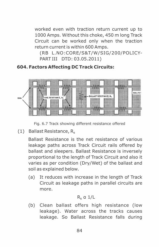
84
worked even with traction return current up to
1000 Amps. Without this choke, 450 m long Track
Circuit can be worked only when the traction
return current is within 600 Amps.
(RB L.NO:CORE/S&T/W/SIG/200/POLICY-
PART III DTD: 03.05.2011)
604. Factors Affecting DC Track Circuits:
Fig. 6.7 Track showing different resistance offered
(1) Ballast Resistance, RB
Ballast Resistance is the net resistance of various
leakage paths across Track Circuit rails offered by
ballast and sleepers. Ballast Resistance is inversely
proportional to the length of Track Circuit and also it
varies as per condition (Dry/Wet) of the ballast and
soil as explained below.
(a) It reduces with increase in the length of Track
Circuit as leakage paths in parallel circuits are
more.
R α 1/LB
(b) Clean ballast offers high resistance (low
leakage). Water across the tracks causes
leakage. So Ballast Resistance falls during

85
rainy season. A good drainage is essential to
avoid water logging and for maintaining a
higher Ballast Resistance. Periodical screening
of the ballast is not only necessary to improve
the strength of track bed but it also increases
the Track Circuit Ballast Resistance.
(c) Calculation of Ballast Resistance, R : B
Measure various parameters as shown in
(Fig.6.7)
Measure the Relay End voltage, VR
Measure Feed End voltage, V F
Measure the feed end current with the help of
multimeter, IF
Measure the Relay End current, IR
Measure length of track, L in mts
Fig. - 6.8 Ballast resistance calculation
=2 (I F – IR)
Average Voltages=R BDifference in Current
V F + V R

86
Enter the measured value in the following
formula:
(d) Minimum Permissible Ballast Resistance for
Track Circuits:
It is considered as: -
(i) 2 Ω Per Kilometer Track Length in Station
Yard, and
(ii) 4 Ω Per Kilometer Track Length - Block
Section (as here, better drainage can be
provided, the track being free from all line
connections).
R from the above formula gives Ballast B
Resistance value for the measured Track Circuit
length L mts. The Ballast Resistance shall be
calculated for per kilometer as described in the
following example.
Say, R is calculated as 10 Ω for 450 mts of B
Track Circuit length.
R for 1mt of Track Circuit length = 10 x 450 = B
4500 Ω
R for 1000 mt (1 Km) of Track Circuit length = B
4500/1000 = 4.5 Ω per km. The derived value
of R > prescribed value, hence Ballast B
Resistance can be considered as optimum.
(2) Rail resistance, R is the net resistance offered by R
the rails. Rail resistance increases with increase in
length of Track Circuit R α L. (Fig.6.9)R

87
(a) Calculation of Rail Resistance, R :R
Measure the feed end voltage with the help of
multimeter, VF
Measure the Relay End voltage, VR
Measure the feed end current with the help of
multimeter, IF
Measure the Relay End current, IR
Measure length of track, L in mts
Enter the measured value in the following
formula:
(b) Maximum Permissible Rail Resistance: -
Generally, the Track Circuit length is limited to
700m Clear Standing Room (C.S.R) length
within station yards. Outside the station
sections, Track Circuits may be longer. The
Fig. - 6.9 Rail resistance
= (IF + IR)
=RRAverage Current
Difference in Voltages
2(VF - VR)

88
condition of rail bonds cannot be checked as
frequently outside the station yards as inside
them. Hence, the need for keeping the rail
resistance minimum there.
Track Circuit length Maximum permissible rail
resistance per Kilometre
Up to 700 m 1.5 Ω
More than 700 m 0.5 Ω
R from the above formula gives Rail resistance R
value for the measured Track Circuit length L
mts. The Rail resistance shall be calculated for
per kilometer as described in the following
example.
Say, R is calculated as 1 Ω for 450 mts of Track R
Circuit length.
R for 1mt of Track Circuit length = 1/450 = R
0.0022 Ω
RR for 1000 mt (1 Km) of Track Circuit length =
0.0022 X 1000 ≈ 3 Ω per km
The derived value of R > prescribed value, R
hence, not suitable for Track Circuit.
605. Resistance Offered by PSC Sleeper:
Measurement shall be made with a sensitive Multimeter of
not less than 20 KΩ/Volt resistance of coil. Megger should
not be used. (Fig.6.10)
After cleaning a spot on the surface of each insert,
measurement shall be made between inserts A & B, A&C,
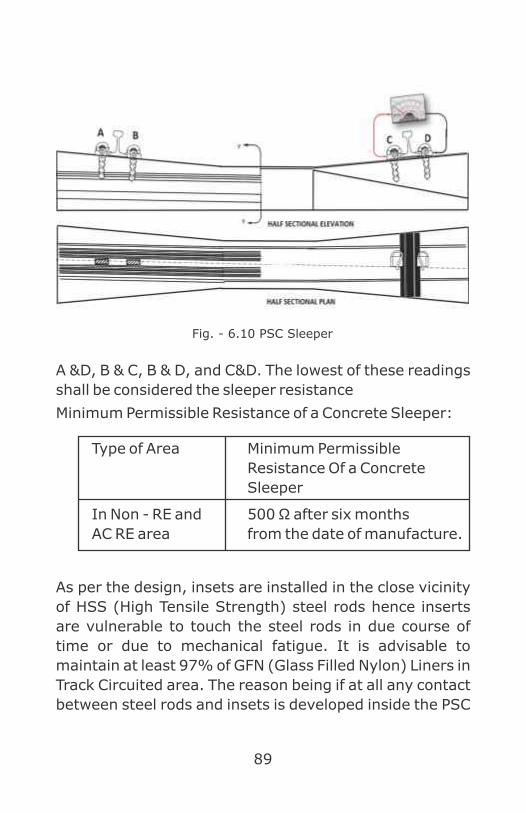
89
A &D, B & C, B & D, and C&D. The lowest of these readings
shall be considered the sleeper resistance
Minimum Permissible Resistance of a Concrete Sleeper:
Type of Area Minimum Permissible
Resistance Of a Concrete
Sleeper
In Non - RE and 500 Ω after six months
AC RE area from the date of manufacture.
As per the design, insets are installed in the close vicinity
of HSS (High Tensile Strength) steel rods hence inserts
are vulnerable to touch the steel rods in due course of
time or due to mechanical fatigue. It is advisable to
maintain at least 97% of GFN (Glass Filled Nylon) Liners in
Track Circuited area. The reason being if at all any contact
between steel rods and insets is developed inside the PSC
Fig. - 6.10 PSC Sleeper

90
sleeper, the GFNL will not allow the Track Circuit current to
pass inside the steel rods through the Elastic rail clip and
insets. Thus Track Circuit will not fail even if sleeper
insulation is low or defective.
606. Track Lead Cables Resistance :
Voltage drop in the Track Lead Cables shall be kept within
limits so as to work sufficiently long Track Circuits with
minimum power application.
Generally, feed equipment is kept in location boxes very
close to the Track Circuits to get better track voltages with
minimum applied source. But longer track lead cables at
the Relay End cannot be avoided at way - side stations
because of the need to keep the Track Relays in the cabins
and avoid thefts. Track Circuit may fail due to poor
insulation resistance of track lead cable too. So these
cable shall be tested by insulation tester (400v).
Insulation resistance of any kind of signaling cable shall
be more than 10 mega ohms.
607. Continuity Rail Bonding :
Fig. - 6.11

91
A straight track portion of welded rails does not need any
props to enhance its conductivity. But if smaller panels or
individual rails are to be included, the ordinary fish-plated
and bolted joints themselves cannot give good electrical
continuity. The rails have to be additionally connected
with Continuity Rail Bonds. 8 SWG Galvanized Iron (GI)
wires are shaped as shown in Fig 6.11 to make 'Rail
Bonds'. To fix a pair of bonds at each rail joint, holes are
drilled on the rails with a 7.2 mm drill. The bond wire ends
are inserted in these holes and channel pins are driven to
hold them tight. Two bonds are used together so as to get
lesser bond resistance at the joints. This also ensures
that one of these bonds at least is always secure
Two types of channel pins are in use. One has only one
grove to hold bond wire. The other one has two groves so
that two wires can be held by the same pin. Two bond
holding clamps called 'Bond Wire Protectors' fixed on the
fish bolts of joint as shown ensure that the bond wires do
not loose-hang, swing under the train and get entangled
with any hanging part of vehicle. It also prevents contact
of rail bond with inserts.
The following precautions shall be taken while providing
these rail bonds:
(1) The bonds shall be fixed without much delay after
drilling holes so that the holes do not get rusty.
(2) Drilling of holes and driving the channel pins through
them shall be done in the same direction to ensure
proper riveting of the pins.
(3) Channel pins shall be driven with a 1½ kg. Hammer
for their proper hugging in the holes.

92
(4) Bond wires shall not be provided between the rails
and fish plates, as they cannot be easily checked.
(5) Holes for bonding shall be as close to the fish plates
as possible.
In addition to these 'Continuity Rail Bonds', in RE
areas, traction power department also provides high
current capacity bonds at the rail joints for traction
return current passage. Traction Bonds (Fig.6.12)
can be found throughout the length of track whether
Track Circuited or otherwise. In fact, traction power
bonds also can serve the purpose of Track Circuit
continuity. But their becoming loose or breaking at
one or two places does not affect traction as much as
it fails the Track Circuit. Hence, providing of rail
bonds by the S&T department is considered
essential at all places. Traction bands are provided
only in negative rail in DC track circuit territory.
Polarity Bond
Longitudinal Bond

93
608. Insulated Rail Joints :
The track portion to be detected has to be electrically
isolated from adjoining rails so as to block the Track
Circuit current, within its boundaries by providing
'Insulated Joints' at each end of the Track Circuit. This is,
however, not necessary in case of coded Track Circuit such
as Audio Frequency Track Circuits (AFTC) & Axle counters.
Structural Bond
Cross Bond
Shunt Bond
Fig. 6.12 : Various Traction Bonds

94
Also on Track Circuits in which additional rail connections
such as turnouts are to be included more insulated joints
are required to include them without shorting Track
Circuit rails. These joints have to be provided in all types
of Track Circuits including coded ones.
Two types of these joints are presently in use,
l Nylon Insulated Rail Joints (Block Joints)
l Glued Rail Joints.
(1) Nylon Insulated Rail Joints (Block Joints)
Block Joints are supplied by S&T department and
installed with the help of engineering officials, which
have to be inserted in the rail joint when Track Circuit
is being installed and also whenever they get
crushed under traffic resulting in insulation failure.
Periodical inspection and renewal shall be carried out
in coordination of S&T and Engg Department (Every
three months, Block Joints shall be opened and
inspected and in every six months shall be
renewed).
The metallic components of the rail joints as
supplied by the Civil Engineering Department for this
purpose are not the usual ones. The fish plates are
planed so as to accommodate insulation liners
between the rails and themselves. The fish bolts
have to be of 140mm length instead of 115 mm.
Also, four steel backing plates have to be provided
for support over the nylon backing plates held by fish
bolts.

95
The insulation components of the rail joint are:
(Fig.6.13)
1) End post 1 Nos
2) Left hand Side channels 2 Nos.
3) Right hand Side channels 2 Nos.
4) Ferrules or Bushes 8 Nos.
5) Nylon backing plates 4 Nos
with collar
6) Nylon backing plates without
collar or as required for packing
nylon washers.
7) Iron backing plates 4 Nos.
These insulation components are available in
different sizes to suite different weights of rails, Viz.
60 kg & 52 kg.
Proper components shall be used according to the
rail weightage. Even left hand side channels and
right hand side channels shall not be interchanged
after locally sizing them up to avoid insulation break
down on these joints.

96
Precautions have to be taken while installing and
maintaining these Block Joints as detailed below: -
(a) The rail ends at these joints shall be cut straight
as otherwise, the nylon end post may break
very quickly.
(b) All the holes on the rails shall be drilled at the
same height.
Fig. - 6.13 - Block Joint
97
(c) The holes in the rails and in fishplates shall be in
correct alignment. Bolts shall not be forced
into the rails, nor shall they be bent and pushed
in as the bushes can thus get crushed.
(d) Rail chairs are replaced by steel bearing plates
on one sleeper each holding rails on either side
of the joint. These plates shall be fixed
sufficiently clear of rail ends to avoid their
short-circuiting.
(e) Dog spikes that hold the bearing plates on to
sleepers shall not touch the fishplates and they
shall be tightly driven in the sleepers.
(f) Packing of a couple of sleepers on either side of
these joints shall always be good and no water
logging shall be allowed near them.
(g) The fish bolts of these joints should not roll due
to swing under the traffic. For this, the steel
backing plates shall be properly bent on the
sides to hold the nuts and bolt heads.
Advantage & Disadvantage: These Nylon joints can
be made with required materials easily at site. These
joints are more prone to failures due to rail creep and
require frequent checking and corrective action.
Hence not favored for high speed / density sections.

98
(2) Glued Joints
Fig. 6.14
Glued Joints are fabricated along with rails at the
manufacturing unit welded at the running track.
Glued Joints are more reliable than Block Joints and
to be maintained by Engg officials. Insulation Joints
are required at the feed and Relay End. Additional
Insulation Joints may be provided within Track
Circuit where ever change of polarity required for
staggering e.g. at Point Zones, Berthing Tracks etc.
These are having more mechanical strength to
retain insulation and to withstand rail creep. The
joints are fabricated in a workshop in 6.5 m Length
and transported to the site for insertion in the track
(Fig.6.14). Laying of these joints involves Civil Engg.
Works viz. distressing of welded rails, welding of the
joints into running track etc.
Chapter no.7 contains brief of Glued Joint regarding
manufacturing, testing, maintenance and laying of
Glued Joints.
609. Additional Insulations on Turnouts in Track
Circuit :
(1) Two or three William stretcher bars provided on
point turnouts have to be insulated in the middle to
avoid a direct short across the track. Two half pieces
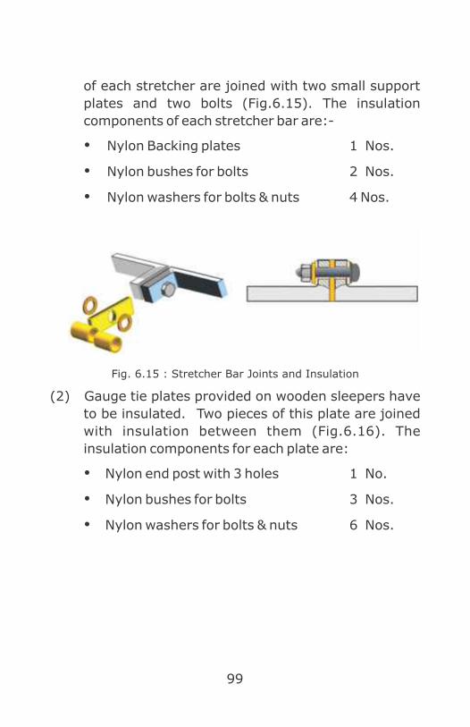
99
of each stretcher are joined with two small support
plates and two bolts (Fig.6.15). The insulation
components of each stretcher bar are:-
Ÿ Nylon Backing plates 1 Nos.
Ÿ Nylon bushes for bolts 2 Nos.
Ÿ Nylon washers for bolts & nuts 4 Nos.
Fig. 6.15 : Stretcher Bar Joints and Insulation
(2) Gauge tie plates provided on wooden sleepers have
to be insulated. Two pieces of this plate are joined
with insulation between them (Fig.6.16). The
insulation components for each plate are:
Ÿ Nylon end post with 3 holes 1 No.
Ÿ Nylon bushes for bolts 3 Nos.
Ÿ Nylon washers for bolts & nuts 6 Nos.

100
Fig. 6.16 Gauge tie plate & insulation
(3) With IRS type point machine
Fig. 6.17 Switch Extension Bracket (D-Bracket) and Insulation
Insulation components provided between each switch rail
and their bracket/clamp attachments are:
Front & Top View Isometric view withnylon insulation
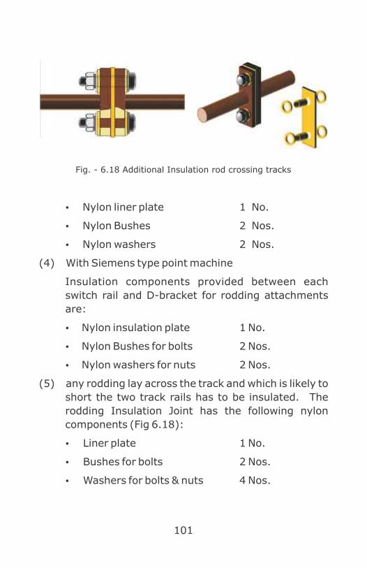
101
Ÿ Nylon liner plate 1 No.
Ÿ Nylon Bushes 2 Nos.
Ÿ Nylon washers 2 Nos.
(4) With Siemens type point machine
Insulation components provided between each
switch rail and D-bracket for rodding attachments
are:
Ÿ Nylon insulation plate 1 No.
Ÿ Nylon Bushes for bolts 2 Nos.
Ÿ Nylon washers for nuts 2 Nos.
(5) any rodding lay across the track and which is likely to
short the two track rails has to be insulated. The
rodding Insulation Joint has the following nylon
components (Fig 6.18):
Ÿ Liner plate 1 No.
Ÿ Bushes for bolts 2 Nos.
Ÿ Washers for bolts & nuts 4 Nos.
Fig. - 6.18 Additional Insulation rod crossing tracks

102
610.Track Circuiting at Fouling Marks & Protection :
Fig. 6.19 Track circuit at point zone

103
(1) A Track Circuit shall extend beyond fouling marks on
both straight road and diversion portions to afford
protection to the standing vehicles. (Fig no. 6.19)
(2) With parallel connection of turnout Track Circuits,
the non-clearance of fouling mark by a vehicle may
not be detected when any connection in the parallel
portion is broken. This shall be checked and avoided
especially in case of the 1 in 8 1/2 and 1 in 12
turnouts. Hence, it is preferable to have series
connection Track Circuits to have fouling mark
protection on running lines.
(3) The end position Block Joints on turnout Track
Circuits shall be so located that not only the last axle
wheels but also the overhanging portions of vehicle
(1.8 m) clear the fouling mark before the Track Relay
picks up. So, in case of Crossovers, Block Joints shall
be provided away from Fouling mark at a distance of
NOT LESS THAN 3 m (towards divergence).
611. Dead Sections in Track Circuits :
These are defined as those portions of Track Circuits in
which occupation by a vehicle cannot be detected. This
may be due to the vehicle shunting rails of the same track
feed polarity. This may also be due to one or both rails of
that portion being bypassed by the track feed.
The following are some of the examples where dead
sections occur:

104
(1) The Block Joints position on track rails is staggered
either (Fig.6.20 & 6.21)
(a) due to unequal rail creep, particularly on
curved tracks.
or (b) due to rail ends on cross-overs being out
of square:-
Fig. 6.20
Fig. 6.21
≤0.8 m
D.S

105
(2) A track portion is excluded from Track Circuit either
(a) due to a level crossing road not allowing Track
Circuiting of the covered area of track
(Fig.6.22):
or (b) due to a bridge or culvert being under the
track (Fig.6.23).
or (c) due to a tram line passing across the
railway track (Fig.6.24).
LEVEL CROSSING
Fig. 6.22
Fig. 6.23
Fig. 6.24
RLY TRACK

106
(3) Trap Circuit for dead zone Track Circuited area.
While allowing for dead sections in Track Circuits, the
following precautions shall be taken so as to avoid
unsafe conditions of traffic over them. The dead
section shall not accommodate a four-wheeler
vehicle entirely in itself without shunting any 'live'
portion of the Track Circuit at the same time. If one
trol ley of an eight-wheeler gets entirely
accommodated in a dead section, the second trolley
of the same vehicle shall not go beyond the live
portion of that Track Circuit in either direction. In B.G
sections, the distance between the two axles of this
trolley is 1.8 m (Fig.6.25). Dead section on point’s
zone shall not be more than 0.8m for B.G section. If
the dead section is longer than 10.8 m as in the case
Fig. 6.25

107
of long bridges underneath the track, a 'Trap Circuit'
shall be provided including the control of dead
section track by two other Track Circuits on either
side which is given below.
612. Maintenance of Track Circuits & Regular
Checks :
(1) T.S.R (Track Shunt Resistance): - Any change of
their components or adjustments shall be
immediately followed by a test of TSR. For this, a
fixed resistance of minimum TSR value shall be
always available with the maintenance staff. For D.C
track Ckts, TSR Shall not be less than 0.5 Ohms.
(2) Track Circuit Test Record Cards: Exact entries shall
be made in them and no detail shall be neglected.
Inspectorial staff shall carefully check these on
every visit. Ballast Resistance value shall
periodically be calculated and monitored to avoid
failures on this count in the near future.
(3) Tri-Monthly Joint Inspection OF SSE/JE(S) with
JE/SSE (P-Way) helps in carrying out timely
preventive maintenance. The joint inspection
involves Block Joints, condition of track ballast and
drainage, clearance of ballast under the Track Circuit
rails and packing of Block Joint and point sleepers.
The broken and crushed insulations of Block Joints
shall be replaced soon.
(4) The condition of rail bonds shall be ascertained by
taking track voltage readings on every fourth Track
Circuit rail at least once in three months to avoid
intermittent Track Circuit failures.

108
(5) Although the point rodding, stretcher and gauge tie
plate insulations do not fail often, the packing
underneath the point sleepers shall be well
maintained. A visual inspection on every visit to the
site, particularly of gauge tie plate joints failure
condition about to develop.
(6) Just before the onset of monsoon, Track Relay
voltages shall be checked once. Also, on clearing of
weather after monsoon, it shall be seen that the
Track Relay voltages do not shoot up beyond safe
limits.
(7) The due date of overhauling shall be noted in paint
on every Shelf Type Track Relay prominently in the
front so that it is not retained in circuit even for one
day after the overhaul falls due.
(8) All the Track Circuit tail cables shall be meggered
once in six months and to be replaced if insulation
resistance is less than 1 Mega ohm.
(9) Signal replacement Track Circuit Insulation Joint
should be kept at distant of 3 Mts from the Starter
Signal post.
613. Track Circuit Failures :
Some guidelines are given below for finding out and
rectifying certain general faults in Track Circuits.

109
Sl.
No. Symptoms Check for Remedy
1
Failure
occurs in
certain
parallel
portions of
Track
Circuit.
(1) Loose or
missing rail
bonds or their
high
resistance.
Replace the
missing bonds or
drill new holes on
rails to reconnect
them.
(2) Broken or
loose feed
Jumpers.
Reconnect them.
2
Failures at
feed end or
Relay End
of D.C.
Track
Circuits.
(1) Excessive
relay voltage
caused by
Charger boost.
Decrease charger
output suitably.
(2) Excessive
relay voltage
caused by
drastic
increase in
Ballast
Resistance.
Readjust the
track voltage
Suitably.
3
Sluggish
Track Relay
operation
with its low
voltage.
Low Track
Relay voltage
caused by (1)
Mains voltage
reduction.
Restore the
health of track
battery in a DC
Track Circuit.
(2) Defective
Block Joints
Replace the
defective
insulation if

110
found. Remove
rail burr or iron
filings on end
post.
(3) Defective
point
rodding or
stretcher or
other
insulations
(a rare
occurrence)
Replace the defective insulation if found. Check carefully for any
small metallic
object wedged
under gauge
plate insulation,
when relevant
sleeper packing is
loose
4
Track Relay drops occasionally
with no
constant
reduction in
its voltage.
1) Loose or
broken rail
bonds
Replace or
reconnect the
defective bonds.
2) Loose
series feed
jumper
connections
or track lead
connections.
Reconnect them
properly
5
Relay
voltage
disappears
for a
particular
setting of
(1) Block Joint
or other
insulation
defect in the
track portion
connected with
Locate and replace the defective insulation.

111
points in the
Track
Circuit.
that point
setting only.
(2) Loose
bonding or
other
connections or
bad jumper
cable
insulation in
the track
portion
connected with
that point
setting.
Replace or
reconnect the
defective bonding
or other
connections and
repair the
defective cable.
6
Track voltage disappears soon after a
vehicle
movement
and
is restored
after
another
movement
Defective Block Joint insulation over which the previous train has just passed before failure.
Replace the
defective
insulation

112
7
Track Relay
dropped
continuously
Low Track
Relay voltage
caused by
faults
mentioned
above.
Necessary
voltage
adjustments or
insulation
replacements or
repairs to
defective
connections as
mentioned
above.
8
Intermittent
dropping of
track
repeater
relay.
(1) Low
battery
voltage after
switching
the charger
off.
Replace the defective cells and boost the charger output for the time being, if necessary.
(2) Loose
battery
connection
Remake a secure
connection.
9
Continuous
dropping of
Track Relay.
Dry solder
developed on
Shelf Type
Track Relay
coil connection.
Replace the relay.
614. Vital Safety Checks for Track Circuits :
(1) Disconnect the Track Circuit feed end if the
same is kept occupied for more than 24 hours
or as instructed.

113
(2) Where there are rusty rails in the Track
Circuited area, Zig-Zag welding using steel
wire should be done on top of the rail to ensure
shunting of Track Circuit by the vehicle.
615. Audio Frequency Track Circuits :
Signaling in auto- sections and IBS requires greater
lengths of Track Circuit. AFTC deals with frequency
modulated signal operated Track Circuit, making a portion
of track tuned to a particular frequency and matching
transmitter and receivers to same modulated signal
(1) Limitations of Conventional D.C Track Circuit:
(a) It is single rail type, i.e. only one rail is available
for traction return.
(b) It needs insertion of insulated Block Joints at all
Track Circuit boundaries. Civil engineering
department is averse to insertion of more joints
as it may lead to weakening of rail and more
maintenance.
(c) Its working length is dependent on immunity of
Track Relay.
(d) Effect of traction harmonics generated when a
thyristor controlled locomotive is worked in the
track that could affect fail safety of the dc Track
Circuit.
(2) Advantages of Audio Frequency Track Circuits
(a) It can be used universally in AC electrified / DC
electrified / non- electrified sections.
(b) Joint-Less in straight portion of tracks.

114
(c) Dependency on other departments is
minimized, as insulated rail joints are
minimized for separation of Track Circuits.
(d) Immune to harmonics - Not affected by
harmonics generated by Thyristor controlled
locomotives.
(e) Double Rail Track Circuit - Both Rails are
available for traction return currents.
(f) Suitable for longer Length Track Circuits. Hence
ideal for Automatic Block signaling.
(g) Remote feeding up to 2.5 km possible.
(h) Bit-coded Track Circuit - to enhance safety &
reliability
(i) Uses FSK / MSK modulation for immunity
against Traction interferences.
(j) Diagnostic LED indications provided for ease of
maintenance.
Other signals like Train speed control and
messages to driver can be superimposed with
train detection signal. So, it is compatible for
cab signaling.

115
Sl.
No D.C. Track Circuits A.F. Track Circuits
1 These work on the
principle of relay
voltage regulation
when vehicles shunt
the track.
Only track voltage gets
reduced in these when
shunted to drop the
relay.
2 Track Relay is
required.
Track Relay is not
required. DC neutral
line relay is used.
3 These are simple in
design and less
costly.
These require more
sophisticated and
costly components.
4 They can be fed
from small
batteries or
rectifiers connected
to AC mains.
Batteries need
more maintenance.
Track feed is given
through individual
conversion units that
need additional
maintenance.
5 Insulated Rail joints
at track ends are
additional sources
of failure in these.
Except points and
crossings insulated rail
joints are not used.
6 Not Immune to
interference and
harmonics.
Immune to
interference and
harmonics.
Comparison Of D.C. & Audio Frequency Track Circuits

116
7 Only one rail is
available for
traction return
current.
Both the rails are
available for traction
return current.
8 Equipment is
required to be
provided in the
trackside location
box.
Equipment can be
provided in centralised
location.
(3) Principle of Working
(a) Audio Frequency Track Circuit (AFTC) works
with modulated signal in audio frequency range
(Fig.6.26)
(b) Each Track Circuit, basic carrier Frequency is
different from adjacent Track Circuit.
(c) An audio frequency Track Circuit includes a
transmitter and receiver
(d) The basic carrier frequency is generated by an
oscillator.
(e) Oscillator is fed with D.C supply from power
supply unit.
(f) Power supply unit gets input 110Vor 230V AC
which is converted to DC through transformer
rectifier and filter circuits.
(g) A portion of track thus tuned to a frequency
receives maximum power from transmitter.
(h) Suitable lightening protection is provided to
tuning unit.

117
(i) Modu la t i on p rov ides sa fe ty aga ins t
interference and coding provides safety against
false fed.
(4) Balancing of traction return current by Various
Bonds
• Traction return current in both rails is to be
given a path for balancing so that there is no
unbalancing in tuned zone connections.
• If the two rails are at a potential difference to
each other, an unbalanced current will flow
through the tuning unit which can burn the
tuning unit resulting into failure.
• For balancing traction return current in tuned
zone Z bond is used in TI-21, ABB AFTC, and S
bond/ALPHA bond in Siemens & ALSTOM AFTC.
(a) S BOND: These are used in straight Track
Circuit between two consecutive AFTCs of
Fig. 6.26

118
same manufacturer. This consists of two semi-
loops each delimited between its centre tap
and its connection point to the rail. The farther
semi-loop of the S-bond is tuned to the
operating frequency of Track Circuit. The other
semi-loop is tuned to the operating frequency
of neighboring Track Circuit. An axle standing
on the S-bond occupies both the near and
advance Track Circui ts thus causing
overlapping of the two Track Circuits so that
there is no detection gap.
(b) End bonds or Alpha bonds (Termination bonds)
These are used in the end of the Track Circuit as
terminal bond. These are provided along with
Insulation Joint for separating AFTC with other
type of Track Circuit (Conventional DC/AC
Track Circuit) or AFTC of other manufacturer.
For traction return current the center of alpha
bond to be connected to next DC/AC Track
Circuit or AFTC of other make.
S BOND
Fig. 6.27

119
(c) Termination with non-Track Circuited portion:
A shunt bond is provided at the termination.
(d) Termination with conventional DC Track Circuit
fig. 6.30
(5) Avoiding interference from adjacent tracks of same
frequency-
For adjacent Track Circuit, same frequency or very
next frequency should not be allocated. There
6.7 m FTG S 46
m 1.75 FTGS 917
ALFA BONDS Fig. 6.28
Shunt Bond
Fig. 6.29

120
should be at least one frequency separation.
Similarly modulating signal, the bit coding type can
be changed with coding plug. Allocation of basic
frequencies and bit coding is called frequency
allocation plan.
(6) Fail-safety-
• Fail-safety-is dependent on correct level
setting of transmitter and receiver level. Drop
shunt test is done with TSR to adjust the
receiver energization level.
• In the event of over energization caused by
inadvertent change from low power mode to
high power mode or by other reasons, the level
of AF signal received at Rx will be beyond the
specified level of demodulator and there will be
neither demodulation nor detection of AF
signal. This will result in the dropping of relay
when the track is free.
• While shunting, the signal level is bound to
come down and fall within the range of
demodulation resulting in detection and output
will be extended to energize the relay when the
track is actually shunted.
Fig. 6.30

121
• Hence, when adjustment in any part of the
Track Circuit is done, all the parameters shall
be checked for their correctness within the
limits specified therein
(7) AFTC installation:
(a) Installation is to be done as per installation
manual of OEM (Or ig ina l Equipment
Manufacturer) by qualified engineers of OEM or
approved agency.
(b) The railway has to prepare frequency plan and
installation plans jointly with OEM.
(c) Frequency Selective Volt Meter (FSVM), True
RMS multi-meter and other measuring
instruments should be used for AFTC
measurements.
(d) Safety tests as specified by the manufacturers
like Directionality test for S bonds, Interference
test, TSR tests and proper Track Circuit
adjustment should invariably be ensured and
recorded before commissioning.
(e) Provision of liners & pads under both the rails,
proper drainage to avoid water logging in the
track, clearance of foot of the rails from ballast.
(f) As AFTC is inherently a double rail Track Circuit,
it is recommended that bonding practice should
be adopted as per provisions of AC Traction
Manual for Double Rail Track Circuits.
(g) Tuning zone must not contain check / guard
rails, level crossing, catch point / expansion

122
joint, TPWS (or AWS) track equipment,
impedance bonds, old bypassed insulated rail
joints and structure bond / cross bond.
(h) Maximum permissible cable lengths between
Transmitter (TX) & its TU (Tuning Unit) and
Receiver (Rx) & its TU with 0.9 mm dia. copper
conductor of quad cable are within limits as
specified in technical & installation manuals of
AFTC.
(i) TX and Rx of same Track Circuits are not run in
one cable. Receivers of different Track Circuits
having same frequency are not run in one
cable. Similarly, Transmitters of different Track
Circuits having same frequency are not run in
one cable.
(j) Cable compensating resistance, line matching
Tuning Unit
Fig. 6.31

123
unit, end terminating unit, equipotential / S / α
/ Shunt bond etc. are used as applicable.
(k) As design of AFTC is specific to make, it would
be preferable not to install variety of AFTCs in a
section from maintenance point of view.
(l) At boundary of AFTC of one make with another
make or DC Track C i rcu i t , spec ified
arrangement as per AFTC’s technical and
installation manuals should be provided and
continuity of traction return current path
should be ensured and strengthened.
(8) Installation guidelines
(a) AFTC of different frequencies are installed
alternatively as per frequency allocation plan.
The units of the same frequency may be
housed in the same location provided they are
fed from separate power supply units.
(b) Tx, Rx, Power Supply Unit, Lightning arrestor
and Relay should be fixed in a half/Full sized
location box near the track as close as possible
to the Tuning unit.
(c) The tuning unit should be fixed inside ME box,
which can be mounted on stakes supported by
a concrete foundation as close to rail as
possible.
(d) All the rails, except those having switch
expansion joints and joints inside tuned area,
in a Track Circuited portion shall be
longitudinally bonded with the help of two 8
SWG GI wire. For bonding switch expansion

124
joints and joints inside the tuned area 19/1.8
mm Aluminum cable using stainless steel nuts
and bolts of M10 X L40 size and copper tinned
lug of 96 sq. mm, M10 round type shall be used.
(e) Testing of AFTC Cable:
Minimum Insulation resistance between each
pair at CT Rack should be more than 10 m
ohms/km and should be recorded & maintained
in the below mentioned sheet. Loop resistance
of each pair should be recorded & maintained
separately. It shall be maximum resistance of
56 Ω/Km at 20 0 C.
(f) Connection of 25 sq. mm copper cable from
Tuning Unit to rail : For connecting 25 sq. mm
Copper cable to rail web. Drill a hole of 19 sq.
mm in the rail web. Insert 12 mm Hex. Head
Bolt. Insert Copper bush and Rivet using
Hydraulic tool. Insert 25 Sq.mm Lug for
connecting the cable. Tighten with washers and
nuts as shown in Fig.6.32 below:
Connection of Electric joint cable to rail using CAD-Weld
25 Sq mm Copper CableConnecon of cable with rail
Fig. 6.32

125

126
CHAPTER 7
Glued Joints
An interlocked yard may have several track circuits
depending upon the number of berthing tracks, point
zones and number of signals, siding etc. Each track circuit
has to be bifurcated physically from the adjacent track
circuits by the means of insulated joints. Glued Joints
bifurcate track circuits physically and electrically too.
Apart of that Glued Joints are having more mechanical
strength to retain insulation and to withstand rail creep
mostly used along with Long Welded Rails.
701. Manufacturing of Glued Joints:
The joints are fabricated in a workshop in 6.5 m Length
and transported to the site for insertion in the track.
Laying of these joints involves civil Engg. Works viz.
distressing of welded rails, welding of the joints into
running track etc.
The drawings for the same of different rail sections are:
Sl. Rail G3(L) type - Specification
No Section 6.5 Mts of fish plates
1 52 kg RDSO/T-671 IRS T-1-2012
2 60 kg(UIC) RDSO/T-2572 IRS T-1-2012
G3(L) type joints are of 6.5 m length and shall be used
with Continuous Welded Rails and Long Welded Rails of 52
kg and 60 kg(UIC) rail sections in all temperature zones of
I, II, III, & IV both in B.G and M.G. These Joints are
replaced once in a Five years or 250 GMT (Gross Million
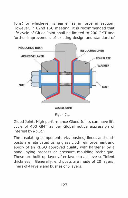
127
Tons) or whichever is earlier as in force in section.
However, in 82nd TSC meeting, it is recommended that
life cycle of Glued Joint shall be limited to 200 GMT and
further improvement of existing design and standard of
Glued Joint, High performance Glued Joints can have life
cycle of 400 GMT as per Global notice expression of
interest by RDSO.
The insulating components viz. bushes, liners and end-
posts are fabricated using glass cloth reinforcement and
epoxy of an RDSO approved quality with hardener by a
hand laying process or pressure moulding technique.
These are built up layer after layer to achieve sufficient
thickness. Generally, end posts are made of 20 layers,
liners of 4 layers and bushes of 5 layers.
Fig. - 7.1

128
After making a rectangular piece of glass cloth
reinforcement and allowing it to cure, it is cut and profiled
to the shape of an end post. The liners are fabricated in
the hollow of a rail web. The bushes are cut to size from a
long ferrule made by winding a wide piece of glass cloth on
a bolt shank layer after layer with adhesive in between.
The fabricated component is able to be separated from
the surface on which it is made due to a coat of a releasing
agent applied beforehand.
All the insulating components (Fig.7.1) of the joint are
stuck in place with an adhesive layer and the bolts are
tightened for a permanent setting. Glued Rail Joints are
available in G3 (L) type having 6 bolts (L-Long)
(1) Material:
The requirement of material for fabrication of one
Glued Joint is given in below. The input materials
shall be procured from RDSO approved suppliers
only. The list of approved suppliers of input materials
is available in Master list of Approved Vendors issued
by Quality Assurance (Civil) directorate of RDSO
which is updated from time to time.
(a) Materials Required for Fabrication of Glued
Joints is tabulated below.
No. Description Quantity (G3 – L)
1 Rail piece of required length
1 No.
2 Fishplates 2 Nos.
3 HTS bolts with nuts
6”

129
4 Punched washers 12”
5 Insulating bushes/sleeves**
6”
6 Insulating liners**
2
7 Insulating end posts**
1
8 Glue Glue consist of epoxy and hardener. The nomenclature of epoxy resin being: Ms CIBA-GEIGY of India’s ARALDITE LY 556; Ms SIP INDUSTRIES Ltd’s EPL 306 and Ms CIBATUL Ltd’s L aprox L-12. The nomenclature of the hardener being Ms CIBA-GEIGY of India’s HARDENER HY 951; Ms SIP INDUSTRIES Ltd’s HARDENER EH 301 and Ms CIBATUL HARDENER L aprox K-6. Hardener and resin shall be mixed in the ration 10:1

130
(b) One rail piece of minimum 4m length shall be
used for fabricating one glued joint. The rail
piece meant for fabrication of glued joints shall
9 Glass cloth carrier/(woven rovings)
4 pieces (15 x 100 cm)
10 Acetone or trichloroethylene or carbon tetrachloride or benzene (for cleaning tools, rails etc.)
Half lit approx.
11 Kerocleanse chemicals for cleaning hands
Half lit approx.
12 Release Agent 25 gm Approx.
13 Sand (For sand blasting)
0.2 cu.m.
14 Cotton waste or liners rags
0.5 Kg approx.
15 Emry cloth no.2 2 sheets
16 Approved paint i.e. red, yellow and blue as per requirement
**The insulating components shall be made at the manufacturing site and shall not be procured from outside agencies.

131
be straight and shall be ultrasonically treated
before issue to the manufacturer. The rail piece
shall be cut in the middle with a rail cutting
machine. It shall be ensured that the cut is
square and the rail ends are square, plane and
smooth. Since rail pieces taken from two
separate rails are likely to have variations in
profile, it is, therefore, necessary that rail
pieces cut from the same rail are jointed
together at the cut end for fabrication of the
joint. For this purpose, just before cutting a rail
pieces, necessary marking (such as A-A’ or 1-1’
etc.) shall be put on the adjoining cut ends with
indelible paint and it shall be ensured that ends
with corresponding mark only are jointed
together. The edges of the rail ends of the two
pieces at the cut shall be finished smooth with a
flat file. All burrs shall be removed. Holes in rail
pieces shall be drilled at locations following the
relevant drawing with a precision drill using jigs
to ensure accuracy. It shall be ensured that the
holes drilled are not skew. The burrs around
holes shall be removed. The edges of the drilled
holes shall be chamfered using the chamfering
tools.
(c) Special fish plates to be used in fabrication of
Glued Insulated Rail Joints shall be inspected by
purchaser Railway or its nominated inspecting
agency (M/s RITES) at the premises offish plate
manufacturer firm. Inspection should be done
as per Para 19 of IRST-1 as amended from time
to time. After inspection every accepted fish

132
plate shall be plainly stamped with the
inspecting officers stamp at one end of each
fish plate on its outer side in the presence of
Inspecting officer. The inspection certificate of
inspect ing agency sha l l be sent by
manufacturer of special fish plate along with
the supply to Glued Joint manufacturer. The
Glued Joint manufacturer will check the supply
with respect to the details mentioned in
Inspection Certificate of inspecting agency and
then only put these in use.
(d) HTS bolts and nuts shall comply with the
following specifications: -
i. "HTS Bolts - Material and manufacturing
process of Hex bolts shall be as per IS:
1363 confirming to property clause 10.9 of
IS: 1367."
ii. "HTS Nuts- Material and manufacturing
process of Hex nuts shall be as per IS: 1363
confirming to property clause 12.0 of IS:
1367."
(e) HTS HEX Bolts and Nuts to be used in
fabrication of Glued Insulated Rail Joints shall
be inspected by purchaser, Railway or its
nominated inspecting agency (M/s RITES) at
the premises of HTS HEX Bolts and Nuts
manufacturer firm. The inspection certificate of
inspec t ing agency sha l l be sent by
manufacturer of HTS HEX Bolts and Nuts along
with the supply to Glued Joint Manufacturer.
The Glued Joint Manufacturer will check the

133
supply with respect to the details mentioned in
Inspection Certificate of inspecting agency and
then only put these in use.
(f) Glass- Cloth Carrier Reinforcement Glass- cloth
carrier reinforcement shall conform to IS:
11273: 1992
(i) Nominal Weight : 360 ±_36 gm/sq. m
(ii) Nominal thickness : 300 ±30 microns
(iii) Construction : I) Ends per 100mm:
61 ±2.5%
II) Picks Weave per
100mm:
55.2 ±2.5 % plain
(g) GLUE: (for making insulating components)
Glue consists of resin and hardener. The
nomenclature of resin & hardener manufactured
by firms approved at present are as under:
Firm’s Name Resin Hardener
M/S Atul Ltd. Epoxy Eposy
Resin Hardener
Lapox L-12 Lapox K-6
M/S. Huntsman Araldite Aradure
Advanced Ly-556 HY-951 IN
Materials (India)
Pvt. Ltd.
Resin and hardener shall be mixed in the
ratio of 10: 1.
Specification and Quality Required of Glue: The
tangential shear strength of glue is claimed to
be about 120 kg/sq.cm by the manufacturer.
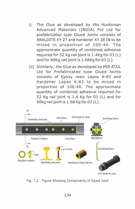
134
i) The Glue as developed by Mis Huntsman
Advanced Materials (INDIA) Pvt Ltd for
prefabricated type Glued Joints consists of
ARALDITE XY 27 and hardener XY 28 IN to be
mixed in proportion of 100:40. The
approximate quantity of combined adhesive
required for 52 Kg rail joint is 1.4Kg for 03 (L)
and for 60Kg.rail joint is 1.68Kg for 03 (L).
(ii) Similarly; the Glue as developed by MIS ATUL
Ltd for Prefabricated type Glued Joints
consists of Epoxy resin Lapox A-83 and
Hardener Lapox K-83 to be mixed in
proportion of 100:40. The approximate
quantity of combined adhesive required for
52 Kg rail joint is 1.4 Kg for 03 (L) and for
60kg rail joint is 1.68 Kg for 03 (L).
Fig. 7.2 - Figure Showing Components of Glued Joint

135
(g) Quantity of raw materials required for
insulating components for 52 kg G3 (L) and 60
kg G3 (L) Glued Joint, with10mm/6mm thick
end post shall be approximately as under.
However, in field performance of 10mm thick
end post is not satisfactory so it is preferred to
use 6 mm thick end post.
(h) Marking of Glued Joints (by manufacturer)-
Every Glued Joint shall have distinctive mark
indicating the Glued Joint number, month and
year of manufacturing and the code of the
manufacturer as shown below. This marking
should be embossed on the gauge and non-
gauge face sides of the head of the rail of Glued
Joint at 300 mm away from the one end of fish
plate by punching without causing any damage
to rail, in letters/digits of 6 mm height at a
depth of 10mm from top of vertical face of rail,
as indicated in figure 7.3.

136
The first four digits indicate the Glued Joint
number starting from 0001 for first joint of
every month, the next two digits’ month of
manufacturing followed by last two digits of the
year of manufacturing. The end letters shall be
code of the manufacturer, assigned by the
Quality Assurance (Civil) directorate of RDSO.
(i) Marking of Glued Joints (by inspecting
authority)- Every Glued Joint shall have
distinctive inspection mark of inspecting
agency. This marking should be embossed on
the gauge and non gauge face sides of the head
of the rail of Glued Joint at 300 mm away from
the another end of fish plate by punching
without causing any damage to- rail, in
letters/digits –of 6 mm height a t a depth of
10 mm from top of vertical face of rail, as
indicated in figure 7.3.
XX.XX MM YY AAA

137
(j) Testing of Glued Insulated Joints
(i) Electrical resistance test should be
conducted and satisfy the following
criteria –
• In Dry Condition: - After preparation of
Glued Joint, meggaring voltage of 100V
DC shall be applied across the joint. The
value of resistance shall not be less than
25 mega-ohms.
• In Wet Condition: -The value of resistance
shall not be less than 3 Kilo-ohms.
Electricity resistance shall be checked
annually during joint inspection by P. Way
& Signal staff and a certificate recorded in
the register.
Figure showing testing of glued joint by insulation tester
Fig. 7.4

138
(ii) Pull out Test:
The pull out test shall be conducted by
suitably gripping the two rail pieces of the
joint and subjecting the joint to axial
tension. One method of conducting the
test is to hold one end of the glued joint
with the help of fishplates as fixed end.
The other end of the glued joint is held to a
moving frame with the help of a wedge
inserted in slots cut in the glued joint
through the moving frame brackets. the
other method of conducting the test is to
hold the glued joint with the help of fish
plates at both ends of the testing frame.
One end of the testing frame remains
fixed and the other is moved with the help
of two hydraul ic jacks operated
simultaneously. Manufacturer can adopt
any other method also with prior approval
of RDSO.
Acceptance Values:
The test joint shall be considered
acceptable if there is no indication of
separation between end posts and rail
end(s) visible to the naked eye at the pull
out load values given in the table below.
Sl Rail Section Minimum pull out load
No. in tonnes G3 (L)
1. 52 kg 150
2. 60 kg (UIC) 170

139
The basis for acceptance/rejection of the
lot with respect to pull out test shall be as
follows:
Four joints should be randomly selected.
Out of these four, two joints are to be
subjected to pull out test. If
l both joints pass, lot is cleared for
insulat ion resistance test in wet
conditions.
l both joints fail, lot is rejected.
l one joint fails, remaining two joints should
be treated and if both pass, the lot is
cleared for insulation resistance test in
wet condition otherwise entire lot is
rejected.
702. Laying of Glued Joint:
(Central Railway letter no.W.827/T-II/Vol.XVII Dt.
24.11.2011)
l At least 10 sleepers on either side of the joint must
be well packed before the joint is inserted to avoid
damage /fatigue of the joint.
l No damage shall be caused to the joint while
inserting.
l While welding the joint with adjoining rails, the heat
shall not spread to the joint. Heating appliances
shall not be applied at a distance of less than 1 m
from the joint.
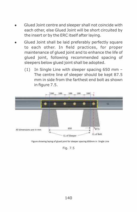
140
l Glued Joint centre and sleeper shall not coincide with
each other, else Glued Joint will be short circuited by
the insert or by the ERC itself after laying.
l Glued Joint shall be laid preferably perfectly square
to each other. In field practices, for proper
maintenance of glued joint and to enhance the life of
glued joint, following recommended spacing of
sleepers below glued joint shall be adopted.
(1) In Single Line with sleeper spacing 650 mm –
The centre line of sleeper should be kept 87.5
mm in side from the farthest end bolt as shown
in figure 7.5.
Fig. 7.5

141
(2) In Single Line with sleeper spacing 600 mm –
The centre line of sleeper should be kept 112.5
mm in side from the farthest end bolt as shown
in figure 7.6.
Fig. 7.6
(3) In Double Line with sleeper spacing 650
mm/600 mm – The centre line of sleeper on
receiving side shall be kept at centre of 2nd and
3rd bolt & on landing side centre of sleeper shall
be kept between centre line of 1st and 2nd bolt
as shown in figure 7.7. This gives us sleeper
Fig. - 7.7

142
spacing of 498mm which is sufficient for
tamping with machines.
(4) Liners & GJ Clip: Specially fabricated GFNL cut
liners shall be used in glued joints due to space
constraint of fish plates & to prevent short
circuiting of track circuit due to rail clips as
shown in fig.7.8.
GJ clip shall be provided instead of J clip in
glued joint area.
(5) Glued joints are provided at the following
locations for ensuring maximum clear standing
length of loop lines.( Railway board letter
no.2012/Safety (A&R)/19/5 Dt.13.06.2013)
(a) Near SRJ of loop line points:
Fig. - 7.8
GJ
Fig. - 7.9

143
(b) Implantation of Loop line Starter Signal near to
Glued joint:
Fig. 7.10
703. Maintenance of Glued Joints:
(1) The ballast used on track in the vicinity of these
joints shall be cleaned to ensure efficient packing
and drainage. Care must be taken to see that the
ballast is clear of rails and rail fastenings. The
clearance from the underside of rail must not be less
than 50 mm.
(2) The joint does not need any special maintenance
than that required for normal track. However, glued
joint shall be kept clean to avoid accumulation of
metal particles which leads to failure of Track Circuit.
(3) As in the case of standard insulated joints, the metal
burrs at the ends of rails shall be removed well in
time to avoid short circuiting through them. This
work shall be done by Engineering staffs skillfully
avoiding damage to end posts.

144
(4) Normally no relative movement occurs between rails
and fish plates at these joints. In case failure occurs
with separation of rail/fish plate surfaces and
relative movement takes place, the damaged joint
must be replaced soon. The electrical resistance of
the joint does not decrease appreciably for a
considerable time even after this separation.
(5) Between two successive tamping of Glued Joints by
track machine, proper maintenance attentions and
inputs should be given to Glued Joints for their
upkeep and proper function.
(6) Life cycle of Glued Insulated Rail Joints is tentatively
fixed at 200 Gross Million Tons of traffic.
(7) Use of GJ clip and cut liners along with GR Sole plate
shall be ensured for proper toe load.
(8) Adequate spacing of sleepers at joint location shall
be such so proper tamping by track machine shall be
ensured.
704. Latest Development on Glued Joint:
With the introduction of higher axle load and increase in
traffic density, the service failure of existing type of glued
insulated rail joints have increased resulting in traffic
disruption. Major type of failures are fish plate failures
and insulation failures. To avoid service failures and to
achieve service life of glued insulated rail joints,
approximately 400 GMT or higher, it is proposed to induct
high performance glued insulated rail joints on Indian
railways. It is also proposed to induct technology for in-
situ re-furbishing of glued insulated rail joint in which the
same glued joint may be used after stripping of glue and

145
other materials from the rail after dismantling the joint
under traffic block of about 02 hours. This type of re-
furbishing can also be done for glued insulated rail joints
which are to be replaced either on service life basis or
condition basis. Performance of these joints in field as well
as drafting of specification of materials is still under
development in RDSO.

146
CHAPTER 8
Electric Point Machine
(IRS:S 24 – 2002)
801. Introduction :
An electric point machine is a device, which can perform
the function of unlocking and operating the point switches
in the desired position lock and detect their correct setting
with the aid of an electric motor, similar to that performed
by an operator through a lever in a mechanical lever
frame. Non-trailable Electric Point Machines 143 mm
throw and 220 mm throw with internal locking conform to
specification No. IRS:S 24 –2002.
The machine shall be of robust construction, securely
fixed and protected from unauthorized interference. The
machine shall be so designed that it can be stopped,
reversed or obstructed at any point during operation
without any damage to bring back the point to its original
position if wrongly thrown over or inoperative due to
obstruction or any other reason. The machine shall be
suitable for either right-hand or left-hand mounting, and
shall be so constructed that it can readily be converted at
site from right-hand to left-hand mounting and vice-
versa. The locking of the points shall be achieved by
means of a locking segment engaging in the locking slot of
the lock slide. The machine shall be enclosed in a strong
metallic weather-proof lockable machine case, designed
for mounting on two sleepers. Suitable hole with
removable vent plug shall be provided at the base for
draining off the accumulated oil or water.

147
802. Manual operation with crank handle :
During the failure of motor, point etc. due to power supply
or for maintenance work, facility must be provided for
locally operating the points manually. For this purpose,
crank handles are provided. Prior insertion of crank
handle, the power supply of point machine shall be
isolated to ensure safety of crank handle user from
sudden operation of point motor if normal supply
resumes. This is achieved by means of cut-out key which
when inserted and turned in clock wise direction, isolates
power supply as well as allows insertion of crank handle
into the point machine. Hence, each crank handle is
attached with a cut-out key.
803. Interlocking of point machine with Crank
handle :
The points in the yard are divided into groups and each
group is provided with an independent crank handle. Each
crank handle is having a unique pattern and the same is
available at point machine also so as crank handle
nominated for certain group of point machines only shall
be cranked. For example, if a crank handle is nominated
for point no. 51 & 52, it cannot be inserted to any point
machine other than point no.51 & 52. Thus wrong
cranking of point machine is avoided. Crank handles are
kept in electrically and mechanically locked condition
inside an Electrical Key Transmitter (EKT) covered with
padlocked glass fronted wooden boxes if provided in
station room. In major yards, such crank handles are
provided in location boxes along with EKT at site for ease
of operation during point failure. Crank handle can be

148
extracted only when all the concerned signal
lever/knob/buttons are at ON. Conversely, when crank
handle is extracted, corresponding point group & signals
become inoperative unless the crank handle is inserted
back to EKT.
804. Operating characteristics :
The max thrust of point machine is factory adjusted 580
Kg. load on throw bar for 143 mm. throw point machine
and not exceeding 700 Kg. for 220 mm. throw in case of
clamp type direct point machine used in Thick web switch.
Operating Data
805. Sequence of operation :
The Electric Point Machine operates in the following
sequence
l Open the detection contacts
l Unlock the points
l Move the points
l Lock the points
l Close the detection contacts

149
806. Electric Point Machine 143 mm Throw with
Rotary Locking :
Salient features:
• Normally 143 mm throw Electric Point Machine
(Fig.8.1) is used with 52 kg and 60 Kg conventional
switches.
• Independent locking of each switch with rotary type
locking arrangement.
• The lock notches are different for Normal and Reverse
position of switch, hence Normal lock slide cannot be
used for Reverse position and vice versa.
• Self-adjustable friction clutch which takes care of
stopping the motor smoothly at the end of each
operation by mechanical braking. No need of electrical
snubbing.
• Detection and controlling contacts are of heavy duty
and self-wiping type.
The possibility of both slides (lock and detection) moving
together due to rust/friction in case one slide connecting
rod breaks is prevented by the provision of brass strips
between them.

150
Brief description of main parts is as under:
Fig. 8.1
(1) Motor: The motor (Fig.8.2) drives the point
mechanism through friction clutch, and throw bar
when electric power is supplied. The motor is an
integral part of the machine, which is removable. It
complies with the requirements of IRS:S37.
Fig. 8.2
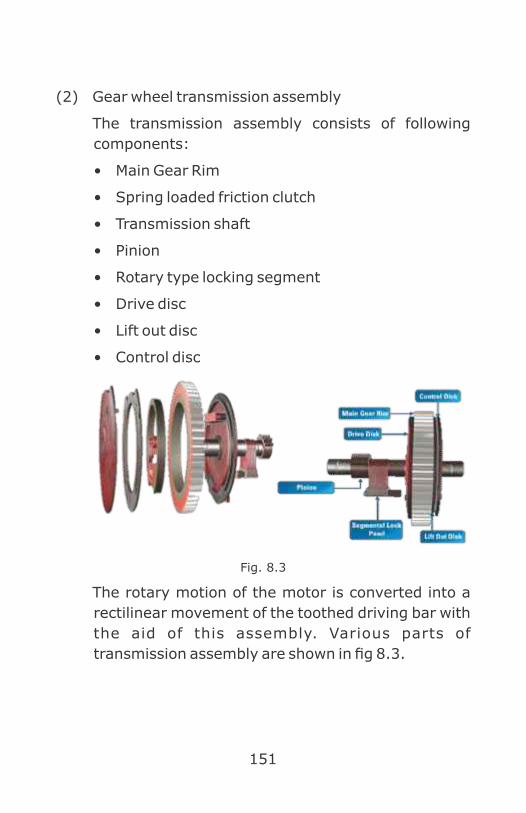
151
(2) Gear wheel transmission assembly
The transmission assembly consists of following
components:
• Main Gear Rim
• Spring loaded friction clutch
• Transmission shaft
• Pinion
• Rotary type locking segment
• Drive disc
• Lift out disc
• Control disc
Fig. 8.3
The rotary motion of the motor is converted into a
rectilinear movement of the toothed driving bar with
the aid of this assembly. Various parts of
transmission assembly are shown in fig 8.3.

152
(a) Main Gear Rim: It is engaged with the motor
pinion and gets rotary motion from the motor
which is restricted to 270 degrees. Gear rim
(Fig. 8.3) transmits the rotary motion to its
centre shaft through spring loaded friction
clutch which in turn imparts 143 mm linear
motion to the throw bar (gear rack).
(b) Control disc: It is used to lock the detector and
control contact actuating roller ‘A’ in a cam
arrangement provided in its periphery (Fig.
8.3).
(c) Lift out disc: It is placed in between gear rim
and control disc. The detection contact
actuating pin roller ‘A’ is allowed to drop in a
smooth cam provided in its periphery, when
point is fully locked in Normal or Reverse
position. Lift out disc (Fig. 8.3) pushes the
roller ‘A’ upwards at the start of unlocking
stroke).
(d) Slip ring: It is supported by a compression
spring (Fig.8.4) with two numbers of expansion
shoe levers (levers L.H. & R.H.) and a bracket
(Retaining strip)

153
Fig. 8.4 Fig. 8.5
(e) Locking segment: The locking and unlocking of
the switches is achieved by means of locking
segment, which moves with rotary motion
clockwise and anti-clockwise and engages in the
locking curve provided over respective locking
bar and driving bar at the end of each operation
(Fig. 8.5).
(f) Pinion: Pinion (Fig. 8.5) having teeth is allowed to
engage with the throw bar during operation after
unlocking, for transmitting linear stroke of 143
mm to move the point.
(g) Drive disc: It is keyed to a driving centre shaft. On
the same shaft, driving pinion and locking
segment are also keyed (Fig.8.3).
Fig. 8.6 Fig. 8.7

154
(3) Bearing pedestals: There are two numbers of
bearing pedestals (Fig.8.6) through which driving
shaft is fitted with machine housing. These pedestals
are made up of cast iron and act like mechanical fuse
in case of trail throw of point thereby reducing the
damage to the point machine.
(4) Friction Clutch: The friction clutch (Fig. 8.7) is a part
of transmission assembly and it is fitted between the
motor and the mechanism to absorb shock at the
end of the operation or in case the machine is
obstructed from completing the movement due to an
obstruction between switch and the stock rail. The
compression spring assembly is inserted in the slip
ring. The complete assembly is fitted inside the main
gear rim and held in position by means of spring
locking plate LH and RH. The spring load on the slip
ring can be increased or decreased by tightening or
loosening a hexagonal adjustable bolt provided in its
assembly. This increases and decreases the friction
load on main gear rim. Since it is pre-adjusted in the
manufacturing place itself, there is no need to adjust
at site.
(5) Driving Bar or Throw Slide: Driving bar (Fig.8.8) or
throw bar imparts stroke required for the operation
of the switches via attached point operating rod.
Throw bar consists of one hole each of 24mm dia. at
its ends and a rack in the middle. The rack pinion
engages with the rack after unlocking and gets a
maximum stroke of 143mm for driving the point
switch rail from N to R and vice versa. Two circular

155
lock notches are also provided for locking the throw
bar at the end of the point operation one each for
point normal and reverse.
(6) Lock slides: The lock slides (Fig.8.9) are
independent for each switch and move along with
the switch rails. In Siemens Point Machine there is
only one common lock slide. These slides are having
one short and one wide circular notch to receive the
locking segment for locking the point in Normal or
Reverse position. A threaded rod is riveted and
welded to one end of the lock slide in which ground
connection rod is connected by using a lug for easy
adjustment of notch position according to the
requirement. The slides position can be changed
only by removing the same from the machine when
the position of the point machine is to be changed
from right to left or vice versa. A brass strip is riveted
to its sides so that, the possibility of moving together
due to rust or friction is eliminated during breakage
of lock rod.
Fig. 8.8

156
Fig. 8.9
(7) Detector slides: The detector slides (Fig. 8.10) are
moved via attached rods by the point tongues and
check whether the point tongues have followed the
movement of the point machine and have reached
the end position.
Fig. 8.10
(8) Detection and control contact assembly: Four sets of
heavy duty self-wiping contacts are provided for (2
sets for control and 2 sets for detection) electrically
detecting the Normal and Reverse position of the
point and to control motor feed. The entire assembly
along with its mechanism is named as switch and
contact pedestal.
(a) Control contacts: The control contacts (outer
ones) are named as Normal control contacts
and Reverse control contacts (Fig 8.11). When
point is set and locked in Normal position, the
Normal control contacts open. Similarly, when
point is set and locked in Reverse position, the
Reverse control contacts open. The position of

157
these contacts depends upon the type of
turnout i.e. LH or RH.
(b) Detection contacts: The inner contacts are
named as Normal and detection contacts.
These contacts (Fig. 8.11) are allowed to make
only when point is fully set and locked in the
respective position. Only one set of contacts
(i.e. Normal Detection (ND) and Reverse
Controlling contact (RC) or Reverse Detection
(RD) and Normal Controlling contact (NC)) are
allowed to make at a time, provided that
rotation of transmission assembly is complete
and both detection slides have completed its
predetermined linear motion of 100 mm in MG
and 115 mm in BG. To achieve the above
condition, notches on detection slides should
align with the position of the roller ‘B’ in the
pedestal assembly and cams in control and lift
out discs should come below roller ‘A’. All these
contacts are actuated only by lift out disc at the
beginning of operation and held in position by
control disc at the end of operation.
Fig. - 8.11

158
807. Ground connections (Fig.8.19)
These provide rigid movable connection between the
Throw bar, detection and lock slides in the point machine
and each of the switches. The ground connections consist
of the following:
(a) Switch extension brackets (P brackets) – 2 Nos.
(Fig.8.12)
Fig. 8.12
(b) Drive Rod or throw rod- 1 No. (Fig.8.13)
Fig. 8.13
(c) Lock rod long (far end) – 1 No. (Fig.8.14)
Fig. 8.14

159
(d) Lock rod short (near end) – 1 No. (Fig.8.15)
Fig. 8.15
(e) Detector rod long (far end) - 1 No. (Fig.8.16)
Fig. 8.16
(f) Detector rod short (near end) - 1 No. (Fig.8.17)
Fig. 8.17
(g) Drive lug – 1 No.& viii. Sleeve arrangement
(Fig.8.18)
Fig. - 8.18

160

161
808. Siemens Electric Point Machine :
Normally all point machines comply RDSO specification
and RDSO drawings except Siemens Electric Point
Machine, which has certain deviations. The main
variations in design of Siemens point machine from that
manufactured as per RDSO drawings are as under:
l Siemens Point Machine is of manufacture’s own
design. The machine complies IRS:S-24 and is
evaluated as per this specification.
l Siemens point machine has common lock rod for
locking both the switch rails.
l Fixing arrangement of point motor in Siemens point
machine is different i.e point motor is fixed on 2 bolts
in Siemens point machine against 4 bolts in RDSO
design.
l Shaft of the point motor is also not held through
bracket in Siemens point machine.
l Gear ratio of Motor pinion and main gear of Siemens
point machine is 16:88 against 12:92 in RDSO
design.
l Superimposed detection facility, hence can work on
less number of conductors.
l Self-wiping type heavy duty control and detection
contacts.
l The threaded portions of the point detection slides
are welded by the slides; hence the slides cannot be
interchanged, thus preventing the unsafe condition.
Locking Slide: It is made up of two parts, main and

162
auxiliary consisting of serrated (toothed) faces and
circular locking notches. These are joined by two bolt
screws with their serrated portions facing each
other. The locking slide is moved via attached rod by
the point tongues and is locked in the same way as
that of Gear rack
(1) Ground connections
The ground connections consist of the following
parts:
l Switch extension brackets (P brackets) – 2 Nos.
l Operating or throw rod. - 1 No.
l Lock rod with stretcher - 1 No.
l Detector rod long (far end) - 1 No.
l Detector rod short (near end) -1 No.
Siemens Electric Point Machine
Fig. - 8.20

163
l Drive lug – 1 No.
l Sleeve arrangement – 1 No.
2. Technical data
• Type of motor…………… ………......110 V Split field,
series wound motor.
• Minimum operating voltage………......60 V DC
• Normal operating current …………….2.5 to 3.0
Amps
• Operating current during obstruction ...3.6 to 3.8
Amps.
• R.P.M………………………………….1700
• Output of the motor……………………0.44 KW.
• Minimum throw of the machine……….94 mm
• Maximum throw of the machine………143 mm
• Type of machine……………………….Combined
• Operating time………………………….3 to 4 Secs
809. IRS Point Machine for Thick Web Switch :
Increased speed limits on the Indian rails have lead to use
of heavier 60 Kg and 52 Kg rails section with thick web.
The conventional point machine with the throw of143 mm
proves inept for the operation of these thick web switches
so IRS point machine throw of 220 mm has been
developed. (Fig.8.22).
(1) Salient features of point machine
(a) The point machine has a throw of 220 mm with
independent lock and detection slides.
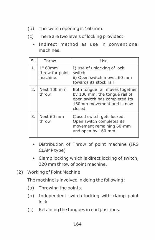
164
(b) The switch opening is 160 mm.
(c) There are two levels of locking provided:
• Indirect method as use in conventional
machines.
• Distribution of Throw of point machine (IRS
CLAMP type)
• Clamp locking which is direct locking of switch,
220 mm throw of point machine.
(2) Working of Point Machine
The machine is involved in doing the following:
(a) Throwing the points.
(b) Independent switch locking with clamp point
lock.
(c) Retaining the tongues in end positions.
Sl. Throw Use
1. st1 60mm throw for point machine.
I) use of unlocking of lock switchii) Open switch moves 60 mm towards its stock rail
2. Next 100 mm throw
Both tongue rail moves together by 100 mm, the tongue rail of open switch has completed Its 160mm movement and is now closed.
3. Next 60 mm throw
Closed switch gets locked.Open switch completes its movement remaining 60-mm and open by 160 mm.
165
(d) Providing possible protection against trailing
point.
(e) Detection of end position of the tongues.
(3) Technical specifications of the point machine.
l Motor- 110V DC, 0.44 KW
l Throw- 220 mm
l Max. Thrust- 450 kg
l Max. operating current - 5.5 Amps.
l Weight of machine- 210 kg
l Slipping load- 700 Kg
The machine is similar in construction to the
conventional machine. The addition being that the
clamp locking is also achieved by the operating rod
itself.
(4) Clamp locking with thick web switch Clamp point
locking (RDSO Drawing No. RDSO/S-3454 for 60 kg
rail and RDSO/S-3455 for 52 Kg rail).
Provides direct locking between tongue rail and
stock rail in closed position.
(a) Firmly holds the tongue rail in the open
position.
(b) Checks any relative movements between
tongue and stock rail.
(c) It ensures and proves the proper setting of
switch and stock rail.
(d) No stretcher bar is used and hence switches are
able to move independently.
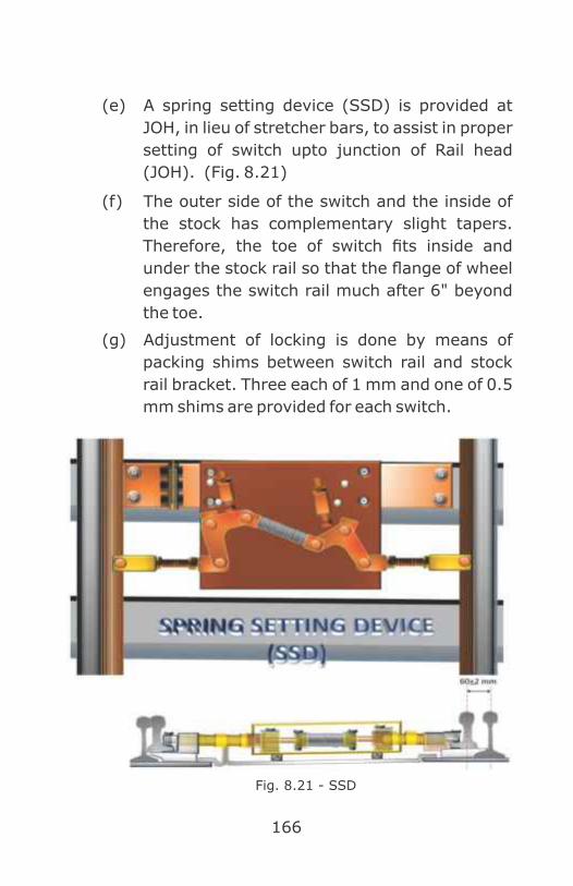
166
(e) A spring setting device (SSD) is provided at
JOH, in lieu of stretcher bars, to assist in proper
setting of switch upto junction of Rail head
(JOH). (Fig. 8.21)
(f) The outer side of the switch and the inside of
the stock has complementary slight tapers.
Therefore, the toe of switch fits inside and
under the stock rail so that the flange of wheel
engages the switch rail much after 6" beyond
the toe.
(g) Adjustment of locking is done by means of
packing shims between switch rail and stock
rail bracket. Three each of 1 mm and one of 0.5
mm shims are provided for each switch.
Fig. 8.21 - SSD
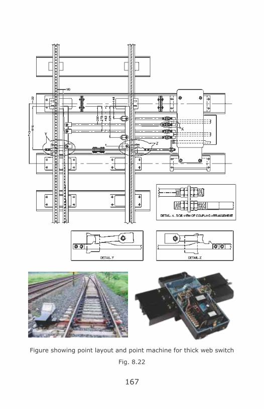
167
Figure showing point layout and point machine for thick web switch
Fig. 8.22

168
(5) Advantage.
It ensures and proves the proper setting of both
stock and switch rails. Due to the 160mm opening of
thick web switch (TWS ) at toe the clearance at
junction of rail head (JOH) is 60mm. This prevents
the repeated striking of the open switch at junction
of rail head (JOH) by inner side of the wheel, which in
conventional switches leads to chances of under
wheel flashing. Clamp locking of the switch prevents
vibration caused in the switch due to train
movement affecting the friction clutch directly. In
conventional switches this leads to reduction in
efficacy of the friction clutch. In a TWS in case of
obstructions like stone pieces coming between
switch and stock rail, the chances of obstruction
clearing by falling down are more as compared to
conventional points in which the obstruction can get
lodged in because of small space between switch and
stock rail. Due to complementary tapers in switch
and stock rail, the switch rail toe fits underside the
stock and therefore the wheel of the train engages
the switch rail well after 6" from toe. Therefore,
damage and wear and tear of the switch is
prevented.

169
CHAPTER 9
Maintenance and Testing of Point Machine
901. Check List of Point Machine Installation :
Ensure that wire connections of the machine are tight and
laced properly.
1. Ensure that the locking segment enters freely into
the notches on the lock slides and with a little
pressure in the notch of drive rod.
2. Ensure the point machine fittings are tight.
3. Check all parts for any crack or breakage etc. and
replace immediately if any defect is found.
4. Ensure smooth working of the gears without any
cracking noise.
5. The slipping of friction clutch during obstruction shall
be ensured and slipping current shall not exceed
twice the normal working current.
6. Ensure that the carbon brushes are exerting
sufficient pressure on commutator. Clean the
commutator properly by using chamois leather.
7. Ensure that all moving parts are free from dust and
are well lubricated.
8. Ensure that gauge tie plate is properly insulated.
9. Ensure that the roller rolls freely on the periphery of
the control and lift out disc.
10. Check that the contact pressure of control and
detection contact is adequate.
11. Apply non-corrosive all temperature grease (IS-
170
507/508) through the entire grease nipple by a
grease gun, after 8,000 operations or six months
which is earlier or as per instructions issued by the
railway.
12. After every six months or as per instructions issued
by the railway pour lubricating oil, SAE-30/SHELL
100, through inlet in to the oil reservoir for
lubricating gearbox of the motor.
13. Pour lubricating oil, SAE-30 on the periphery of
control and lift out disk and felt pad provided over
the driver rod and the lock slides.
14. Check the overload current.
15. Track Locking
16. Check track locking once in six months or as per
instructions issued by the railway.
902. Maintenance of Point Machine :
1. Lubricate all the moving parts the clamp lock
assembly.
2. Put grease on the bronze brush in the lock arm
assembly.
3. Put grease on the notches of the lock slide and
fishtail portion of the lock arm.
4. Loosen the nuts of stock rail bracket so that it can be
move freely in its oblong holes and takes its own
portion.
5. Operate the machine with crank handle and adjust
the lock and detector slides usually (Near end first)
6. If clamp lock is not locking point, then do the
following.

171
7. For proper locking on both sides additional numbers
of packing shims have been provided between
switch rail and tongue rail bracket.
8. Required no of shims will be put outside the tongue
rail bracket to facilitate locking on either side.
9. Six numbers of packing shims are provided with
each clamp point assembly.
10. Now tighten the nuts of the stock rail bracket.
11. Workshop Overhaul after 4,00,000 operations or five
years for bigger yard or seven years whichever is
earlier. The point machine should be taken out and
should receive a general overhaul and thorough
cleaning in an authorized workshop.
903. Testing of Point Machine :
After installation the following test should be carried out.
(1) Obstruction test:
(a) The detector slides lock slides and drive rod
must be so adjusted that with 5mm thick test
piece placed between the switch and gauge
face of stock rail at 150mm from the toe of the
point (Fig. 9.1) (Ref: SEM Part II Para 19.38).
Fig. 9.1

172
(b) Friction clutch de-clutches the motor from
mechanism.
(c) The point cannot get locked either by clamp
lock or in the point machine.
(d) Lock segment does not enter into the notches
of locking slides.
(e) Switch detection contacts do not make.
(f) The slipping current is not exceeding twice of
the normal working current.
(2) Measurement of working voltage and Current of
Point Machine
Operate the machine electrically and measure
working current and voltage for both Normal and
Reverse operations with and without obstruction.
Ensure that the friction clutch declutches during
operation with obstruction.
(a) Current measurement
Method 1. Measurement of Motor Current by
Multimeter.
(i) Insert the cutout key and turn to break
crank handle cut-out contacts
(ii) Connect the ammeter in series between
CH1 and CH2 terminals.
(iii) Operate the machine electrically.
(iv) Measure the working current as shown in
fig. 9.2.

173
Fig. 9.2
Method 2. Measurement of Motor Current by
Clamp Meter. (Fig.9.3)
Fig. 9.3
Cutout key is not necessary to measure motor
current by this method. Hence this method is
extensively used in field.
(i) Set the clamp meter in DC Amp mode by
the selector switch.

174
(ii) The moveable Jaw of clamp meter can be
opened by pressing the knob.
(iii) CW conductor can be clamped as show in
figure.
(iv) Operate the point machine and the digital
display shows current of point machine
instantaneously.
(b) Voltage measurement
Measure the voltage (Fig.9.4) for normal and
reverse operation by connecting voltmeter
probes directly to the motor terminals (1 & 2 for
Reverse operation, 2 & 3 for Normal operation).
The above parameters of current and voltage
measurement should be taken every 3 months
and recorded as given in following table:
Fig. 9.4

175
(c) Crank handle cut out contact testing
Check the wire connections to the terminals of
voltage cut-out switch and ensure their
intactness. Open the voltage cut-out switch
and ensure that the contact is not giving break
in circuit and making with sufficient pressure.
(d) Detection contact testing
To check the individual integrity of point
detection contacts,
(i) Open the transparent cover of switch
pedestal.
(ii) Break each detection contact one by one
manually.
(iii) Check that the corresponding detection
relay in the relay room drops each time
the detection contact is broken.
(iv) Operate the machine by power and check
that the contacts are making with
sufficient pressure.
(e) Correspondence testing
Correspondence testing of point at site with
respect to point group/relay and panel
indication must be done after cable meggering
and each time the point is reconnected after
disconnection for maintenance/repair.
(f) Track locking testing
Shunt any one of the track circuit on point
portion with proper track shunt and ensure that
the point track indication on the lever

176
frame/panel is showing occupied. Operate the
point from the cabin/panel. Ensure that the
point does not operate in this condition.
Remove the shunt and ensure that the point
gets operated. This test shall be done both for
normal to reverse and reverse to normal
operation. Track locking should be tested once
in three months.
(g) Insulation test.
Check the insulation of the following.
(i) Point machine is insulated from ground
connection.
(ii) Spring setting device & Clamp lock
assembly is Insulated from both the rails
(for TWS).
(iii) Leading and following stretcher bar
(iv) Check insulation once in six months or as
per instructions issued by the railway.
(h) Electrical Insulation Testing
(i) Operating values of point machine, point
motor insulation and switch bracket
insulation should be tested once in three
months.
(ii) Tail cable testing with 500 V megger and
pot box wiring should be performed once
in six months.

177
904. Maintenance of Switch Assembly :
1. Ensure graphiting or lubricating of slide chairs at
every week.
2. Ensure that all nuts and bolts are tight and split pins
are opened properly.
3. Check that the point area is well ballast, packed and
free from vegetation
4. Lubricate at the following moving parts of the clamp
lock fortnightly (for TWS)
l Stock rail bracket groove.
l Moving part of tongue rail and lock arm
assembly.
l Between machine of lock bar and lock arm
assembly.
5. Ensure that the rodding and other connections are
tight.
6. Check that water does not stagnate in the vicinity of
points.

178
905. Troubleshooting :
SN Nature of Failure
Cause Remedy
1 Tongue rail not housing up to adequate sleepers or tongue rail housing one side properly but not housing another side at adequate distance.
Spring setting device not adjusted properly
Arrange P-Way staff for proper adjustment of spring setting device.
2 Clamp lock not locking point on either side.
Packing shims between stock rail and tongue rail bracket or outside the tongue rail are to be adjusted.
Adjust the numbers of packing shims of tongue rail bracket.
3 Point machine does not start.
Fuse blown Off.
Replace with same.
Feed is not coming out from relay room.
Check the circuit and rectified
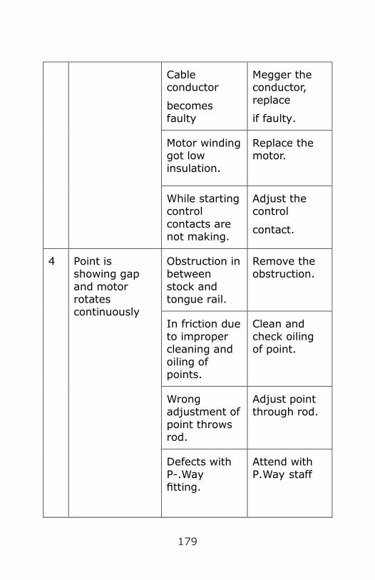
179
Cable conductor
becomes faulty
Megger the conductor, replace
if faulty.
Motor winding got low insulation.
Replace the motor.
While starting control contacts are not making.
Adjust the control
contact.
4 Point is showing gap and motor rotates continuously
Obstruction in between stock and tongue rail.
Remove the obstruction.
In friction due to improper cleaning and oiling of points.
Clean and check oiling of point.
Wrong adjustment of point throws rod.
Adjust point through rod.
Defects with P-.Way fitting.
Attend with P.Way staff

180
5 Point is properly set, but motor continuously rotates.
Respective detection contacts are not making (Point may lock)
Adjust detection contact.
Adjustment required in lock rod, if point is not locked.
Adjust lock rod for proper locking.
The respective detection terminal loose or broken in point machine.
Attend respective detection contact.
6 First point is correctly set, locked and detection contacts are making, but feed not extended to IInd point machine.
Feed not coming to IInd point machine due to cable between the machine defective.
Check cable conductor between point machine, replace if defective or low insulation.
Crank handle contact of IInd point machine not making.
Adjust crank handle contact.

181
Respective terminal loose or broken in IInd point machine.
Tighten terminal or replace broken terminal.
7 While operating the points the motor rotates in just reverse direction.
Any wire interchanged.
Check wiring and rectified.
In point junction box cable interchanged.
Check wiring at junction box and rectified.
8 First point is correctly set, locked and detection made but the motor do not stop even after starting of IInd point machine.
Short circuit faults in the terminals in point junction box.
Check wiring at junction box and rectified the short circuit faults.
9 Out of correspondence between point and relay group.
Cable inter changed in point junction box.
Check and rectified.
Wiring inter changed in crank handle box terminal.
Check and rectified

182
906. Do’s and Don’ts. :
Do’s.
1. Get disconnection of point, before carrying out any
work.
2. Always ensure schedule maintenance.
3. Test the working of friction clutch.
4. Do ensure that track locking, route locking, crank
handle release locking are effective.
5. Do test the correspondence of the points with
indication at panel or cabin.
6. Always use proper lubricant. Wipe away excessive oil
or grease.
7. Always use proper rating of fuse.
Don’ts.
1. Do not operate the point manually except through
specific crank handle.
2. Forget to exercise safety checks initially, during and
after disconnection.
3. Forget to carry necessary tools while attending the
failure.
4. Leave any discrepancies noticed in the point
machine.
5. Use too much lubricant.
6. Allow unsquared notches on slides.

183
CHAPTER 10
Axle Counters
Conventional DC track circuit is depending on track
parameters such as ballast resistance, sleeper resistance,
climate, insulated rail joints and GFN liners and length of
track circuit is limited to 750 mt only. Moreover
maintenance attention is required from Permanent way
officials to upkeep track parameters within requisite
value. Audio frequency track circuits are introduced to
overcome such limitation but since complete dependency
on track cannot be eliminated, Axle counters are
introduced in Indian Railways.
1001. Salient Features of Axle Counters :
l Axle counters can work on any kind of sleepers and
liners.
l Insulated rail joints are not required even in points
and turnouts.
l Train detection is feasible at steel girder bridges,
tunnels and specially water logged areas.
l Range of operation may extend upto 20 Km.
1002. Application of Axle counters :
(1) Axle counter can be used in conjunction with the
existing block instrument to ensure complete arrival
of train from block section to station section, e.g.
Block Proving Axle Counters (BPAC)
(2) Axle counters can be used in conjunction with DC
track circuit and or AFTC for dual detection to
enhance redundancy.

184
(3) Axle counter can also be installed in lieu of block
instrument. E.g: Universal Fail Safe Block Interface
(UFSBI)
(4) Axle counter can be used in lieu of track circuits for
train detection. E.g: Multi Section Digital Axle
Counters (MSDAC).
(5) Axle counter is used as an integral part in
Intermediate Block Signaling (IBS).
Fig. 10.1
Fig. 10.2
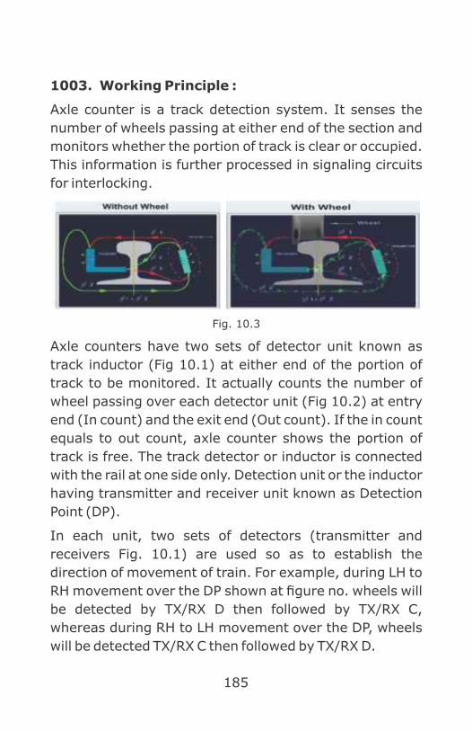
185
1003. Working Principle :
Axle counter is a track detection system. It senses the
number of wheels passing at either end of the section and
monitors whether the portion of track is clear or occupied.
This information is further processed in signaling circuits
for interlocking.
Fig. 10.3
Axle counters have two sets of detector unit known as
track inductor (Fig 10.1) at either end of the portion of
track to be monitored. It actually counts the number of
wheel passing over each detector unit (Fig 10.2) at entry
end (In count) and the exit end (Out count). If the in count
equals to out count, axle counter shows the portion of
track is free. The track detector or inductor is connected
with the rail at one side only. Detection unit or the inductor
having transmitter and receiver unit known as Detection
Point (DP).
In each unit, two sets of detectors (transmitter and
receivers Fig. 10.1) are used so as to establish the
direction of movement of train. For example, during LH to
RH movement over the DP shown at figure no. wheels will
be detected by TX/RX D then followed by TX/RX C,
whereas during RH to LH movement over the DP, wheels
will be detected TX/RX C then followed by TX/RX D.

186
Transmitter coil is feed with specified alternating current
from the track side axle counter equipment box, which
generates alternating electromagnetic flux and voltage
induced in the receiver coil due to the flux linkage (Fig
10.3). The track side equipment is receiving the nominal
voltages induced in the receiver coil until the passage of
train wheels. Once train wheel passes over the detector,
the alternating flux get distorted (Fig 10.3) due to the
presence of train wheels and subsequently amplitude and
or change of phase in the receiver coil voltage is sensed by
the track side equipment. This change in amplitude and or
change in phase or receiver voltage is processed by the
electronic circuit for counting the wheel on each sorts of
obstruction by rail wheels.
1004. Types of Axle counters :
Types of axle counter as per number or detection points
(DP)
1. 1D – Single Detection point
Uses: Normally used in berthing portion of
termination stations, long siding with dead ends.
2. 2D- Two Detection point
Uses: Normally used in berthing portion, long siding
with entry and exit ends, block section.
Fig. 10.4
Fig. 10.5

187
3. 3D- Three Detection Points
Uses: Normally used at point zone area.
4. 4D- 4 Detection Points
Uses: Normally used at more than one point and
crossing area.
1005. Analogue Axle counters :
• Use 5 Khz of frequency for both the transmitter of
each detection point
• Use electronic logic circuits. (Fig 10.8)
Fig. 10.6
Fig. 10.7
Fig. 10.8

188
1006. Digital Axle counters:
• Use microprocessor/microcontroller based system
• Use two separate frequencies of more than 20 KHz,
one for each transmitter coil at each detection point
(Fig.10.10)
Digital Axle counters are further divided as
(1) Single Section Digital Axle Counters (SSDAC)
Single section axle counters (Fig 8.9) are
generally used to monitor a single track section
i.e there is only one entry point and one exit
point for a particular track section. Digital data
is transmitted directly between two axles
counter field equipment by means of modem
communication. E.g: BPAC & IBS.
(2) Multi Section Digital Axle Counters (MSDAC)
MSDAC used to monitor a portion of line called
as “Track Section (TS)” confined by multiple
Entry & Exit points (Fig 10.10). There are
counting heads (Axle Detectors) at the
CELL ALCATEL GeneralElectrical
GG TRONICS
Different make of Digital Axle
Fig. 10.9

189
beginning and end of each track section. These
units are connected to an evaluation computer
(Central Evaluator) which processes the
information generated by the counting heads.
If the number of axles counted in matches that
counted out, the respective track section is
indicated as being clear.
Multi Section Digital Axle Counter can be easily
configurable as per yard layout in different
track sections as given below
(a) One detection point single section: In
terminal lines/siding.
(b) Two detection points single section: In
straight line.
(c) Three detection points single section: In
point zone.
(d) Four detection points single section: In
point zone.
(e) Multiple detection points single section: In
ladder.
(f) Consecutive single section in a straight
line.
A typical layout given below explains the
working of a Multi-Section Digital Axle
Counter having a Central Evaluator
supporting 5 nos. detection points.

190
1007. Resetting of Axle Counters :
SSDAC:
Axle counters can be reset in case of failure. The SM on
duty shall ensure complete arrival of last preceding train
before initiating resetting process. For axle counter
resetting in BPAC, cooperation required from SM of
advance station. The procedure is enlisted below.
Fig. 10.10

191
1008. Trolley Suppression Technique in Digital Axle
Counter Section :
Push Trolleys may be put on any part of Track randomly
and may pass at Detection points and may be withdrawn
of Axle countered track section randomly causing Track
occupation indication and failure of Signals. These Push
Trolley wheels should not get detected for counting
purpose and are to be suppressed. In Digital axle counters
as the system will take care of validation of generated
pulses caused by passage of wheel over the track device,
depending up on the phase shift of the pulse. (This phase
shift of the pulse may be normally 160° to 180° for a train
wheel and it may be approximately 100° to 120° for a
push trolley wheel). Even though Digital Axle counters are
designed not to detect push trollies, but it is observed that
axle counters are failing due to detection of push trollies.
Hence, Axle counters are interlocked with the existing DC
track circuit over which it is installed in such a manner that
axle counter shall respond and start counting of axles
when track circuit is down. As the push trolley axles are
insulated, track circuit shall not fail due to push trolley
movement & therefore push trolley shall not be detected.
192
CHAPTER 11
Dataloggers
1101. Introduction :
Datalogger is a Microprocessor based data recording
system, which helps in analyzing the failures of relay
based interlocking system/ Electronic Interlocking
system. The information/ data can be transferred to the
computer to analyze further “on line" / “off line” analysis
of stored data. A print out also can be obtained through a
printer by connecting directly to the datalogger unit. The
data belongs to Relay contacts is considered as digital
inputs and the data belongs to voltage levels/ currents is
considered as Analog inputs.
Dataloggers are mandatory for all new relay interlocking
(PI/RRI) , EI installations and it is also recommended to
provide in all existing PIs / RRIs. In mechanical and
electro mechanical interlocking yards, datalogger
monitoring is not possible.
It is a vital tool for accident investigation. Datalogger is
used at Stations / yards, whereas in case of Auto Section,
IBH and interlocked LC gate locations, Mini dataloggers
are used and called as Remote Terminal Unit (RTU).
1102. Advantages of Dataloggers :
(1) Dataloggers helps in monitoring the typical failures
such as intermittent, auto right/Subsequently got
right failures.
(2) It helps in analyzing the cause of the accidents.

193
(3) It helps in detecting the human failures / errors such
as:
(a) Drivers passing signal at Danger (SPAD).
(b) Operat ional mistakes done by panel
operators/ASM’s of operating department
(Wrong Operation)
(c) Signal and telecom engineering interferences
in safety circuits.
(d) Engineering and electrical department
interferences / failures.
(e) It helps as a “TOOL” in preventive maintenance
of signaling gears.
(4) Dataloggers can be connected in network.
Networked dataloggers helps to monitor the
PI/RRI/EI remotely along with continuous data
backup.
(5) Failure reports can be generated remotely with the
help of datalogger network.
(6) Failure message can be generated and may be
conveyed to all concerned officials through SMS as
soon as failure occurred in the section. (Additional
Hardware to be installed for this purpose along with
the datalogger)
(7) On line and Off line track simulation is possible.
(8) Speed of the train on point zones can be calculated.
(9) Age of the equipment in terms of number of
operations. etc. may be calculated.

194
(10) Following data may also be fetched through
datalogger:
(a) Train Detained – after signal
(b) Train Speed
(c) Train speed in Loop line
(d) Train Stop
(e) Non-Signal Movement
(f) Driver Entering into Block Section without Line
Clear
Fig. 11.1

195
(g) Operation of More than one point at a time
(h) Point operated with repeated operations
(i) Late Start of train
(j) Late Operation of signals
(k) Premature Operation of block instruments/
Signals
(l) Route Cancellation
(11) Point Maintenance
All the dataloggers requires a potential free (spare)
relay contact for monitoring digital inputs through
Digital input cards & for monitoring Analog inputs
such AC/DC bus bar voltage levels through Analog
input cards (Fig 11.1).
Provision of Dataloggers is mandatory with RRI
systems and is optional for PI systems as per
amendment to the specification for Relay
Interlocking systems (IRS/S-36). The data collected
by the datalogger can be used for failure analysis,
repetitive discrepancies, and for accident
investigations.
1103. Hardware (Equipment) :
Datalogger system consists of:
l Datalogger (CPU - with Microprocessor 68000)
l Digital input cards.
l Dual modem card.
l Digital Scanner units (DSU)
l Analog Scanner units (ASU)

196
(1) CPU Card
It is provided with Motorola microprocessor M
68000. It performs all the activities pertaining
to the datalogger. It continuously scans (check)
the Digital inputs(inbuilt), Digital Scanner
Units and Analog Scanner Units. i.e., scanning
of digital signals (Relay operations) for every
16-milli seconds and scanning of analog signals
(i.e. AC/DC voltages & DC currents) for less
than 1 second.
This card will support the I/O interfaces of LCD
(Liquid Crystal Display) - 2X24 alphanumeric,
Key Board, LED Matrix Display, Real Time
Clock.
LCD display and keyboard: This acts as man
machine interface between the datalogger and
the signal engineer. All the operations
Fig. 11.2
197
(Software) can be performed using this LCD
and keyboard.
Real time display with 7 Segments: This is built
in real time clock within Datalogger and its
current time will be displayed on six 7-segment
display provided.
CPU card continuously scans (checks) the
Digital & Analogue Scanner Units. When CPU
card scans the digital inputs, it compares with
the previous stored data and if there is any
change from the previous status then only that
data will be stored (the status / conditions of
relay) with date and real time. A total of
minimum 10 Lac events can be stored in
memory on first in first out basis so that latest
data is available in the system. There is no loss
of historical data from datalogger memory in
case of power supply failure of datalogger.
(2) Digital Scanner Unit (DSU)
Each DSU contains 8 nos. of Digital Input cards.
Each input card can be connected with 64
inputs. Total input capacity of DSU unit is 512
inputs. More number of DSU can be added if
number of relay inputs are increased.
(Fig.11.3)

198
(3) Analog Scanner Unit (ASU)
ASU contains maximum 3 nos. of Analog input
cards. Each input card can be connected with
8nos. of Analog inputs. Total input capacity of
the ASU is 24 analog input channels. Maximum
4nos. of ASUs can be connected to the system.
Analog input channel capacity of the system is
96. All these analog inputs are scanned at a
rate of less than 1 sec. (Fig.11.3)
(4) Internal modem card / Dual Modem card (in-
built)
It is fixed in datalogger Euro rack itself. One
card contains two modems. The top modem is
called ANS (answer) modem and the bottom
modem is called as ORG (originate) modem. It
is used in case of networking of Dataloggers. In
network, connect ‘ANS’ modem to the ‘ORG’
modem of one adjacent station and connect
Fig. 11.3

199
‘ORG’ modem to the ‘ANS’ modem of other
adjacent station.
1104. Digital inputs :
(1) Field inputs: All TPRs (Track Relays), NWKRs
(Normal Point indication relays) RWKRs (Reverse
Point indication relays), ECRs (signal Lamp checking
Relays), Crank Handle relays, Siding, Slot, LC gate
control relays etc.,
(2) Control Panel inputs: All button / Knob, SM’s Key
relays.
Internal relays: All HR, HHR & DR (Signal clearance
relays), WNR, WRR (Point initiation relays), ASR
(Route releasing relay), UCR (route checking relay)
etc.
1105. Software Modules of Dataloggers :
l Reports.
l Fault Entry.
l Track Offline/Online Simulation.
l Train Charting.
1106. Network Management of Datalogger
Software features :
l Online Relay Status
l Online Faults - To view information of various Online
Faults, as they occur in the stations where the
Dataloggers are connected.
l Online Simulation - Graphical view of relay
operations, train movements, etc.

200
l Remote monitoring of stations with the help of
NETWORKING.
1107. Software objectives :
l Predictive Maintenance.
l Easy identification of failures.
l Crew discipline.
l Train charting.
1108. Easy/Quick identification of Failures :
(1) TPRs: (Track Repeating Relay at Relay Room)
Fails: If TPR1, TPR2, TPR3 are in sequence
then If TPR1 UP, TPR2 DOWN, TPR3 UP-
Triggering signal is TPR2 (fig 11.4).
Fig. 11.4
(2) Bobbing: If TPR (track relay) is DOWN to UP or
UP to DOWN Within the time interval.
(3) Point Machine: (NWKR: Normal Point Detection
Relay, RWKR: Reverse Point Detection Relay)
Fails: NWKR is down and RWKR is down for
more than given time interval
Fig. 11.5
TPR1 TPR2 TPR3
TPR1 TPR3 TPR2
POINT NO INDICATION

201
(4) Loose packing (fig 11.5)
When TPR1 is down, then the corresponding
NWKR, RWKR both Down. Triggering signals
are NWKR, RWKR.
(5) Blanking of Signals (Fig.11.6) :
RECR (Red lamp checking relay) down and
HECR (caution lamp checking relay) down and
DECR (Proceed lamp checking relay) down for
more than given time interval.
Fig. 11.6
(6) Flown back to danger: If UCR (Route Checking
Relay) is UP, HR (Signal clearing Relay) is
DOWN and RECR (Red Lamp checking relay)
should be UP & TSR (Track stick Relay) is UP.
Fig. 11.7
(7) Signal passing at Danger (SPAD) - TPR1 Down,
RECR (Red Lamp Checking relay) UP before
TPR2 Down, TPR1 and TPR2 are in sequence.
NO INDICATION
S1 KNOB S1

202
(8) Calculation of Train Over Speed with the help of
Datalogger:
• Prerequisite Data to be fed in datalogger:
Length of track circuit & Maximum Permissible
Speed of the section.
Example:
Timer Starts as soon as Track 2 is down when Track
1 is already down. Say, time t1.(Fig.11.9)
Timer Ends as soon as Track 3 is down when Track
2 is already down. Say, time t . (Fig.11.10)2
Length of Track 2 is already measured and fed to
datalogger.
Track1 Track 2 Track 3
Fig. 11.9
NO INDICATION
Fig. 11.8
Track1 Track 2 Track 3
Fig. 11.10

203
Suppose, Length of Track 2 is 100 mts.
t , time when track 2 is down is 10hrs 10 min 25 sec.1
t , time when track 3 is down is 10hrs 10 min 30 sec.2
t – t = 5 sec. ………..(a)2 1
MPS is 50 Kmph i.e. 13.9 mt/sec.
110% of MPS is 15.27 mt/sec.
= 6.54sec. ... (b)
As, a<b, hence train is over speeding.
Actual Speed of train is length of track (Track 2) /
t -t = 100mt / 5 sec.2 1
= 20 mt/sec. (i.e. 72 Kmph) which is higher than
110% of MPS.
1110. The datalogger equipment is capable of
generating following exception reports :
l Battery Low voltage.
l Battery charger defective.
l Under wheel flashing of points.
l Signal lamp failure.
l Blanking of signals.
l Route section not released after passage of train due
to track circuit failure.
l Point failure point detection not available after set
time period.
l Track circuit failure.
l Fuse blown OFF.
Length of Track
MPS110%
100 Mt.
15.27 Mt./Sec.=

204
l Timer not properly set for 120 Sec.
l Sluggish relay operation.
l Signal cable low insulation.
l Route not set when operations valid.
l Push button stuck.
l Signal over shoot
l Wrong operation.
l Axle counter RX low level.
l Bobbing of track, point, signal, crank handle, level X-
ing or Ground frame repeater relay.
l Point repeated operation.
l Non-sequential shunting of tracks.
1111. Various Fault Logics Used in Datalogger :
SL.
Fault
name
Fault description Probable
reasons
1 Signal
Bobbing
The time
difference
between ECR
(UP to DOWN to
UP)is in between
500 ms.to 2
seconds which
should be taken
as 1 count and
for satisfying the
fault logic 2 to 3
counts should
happen within 10
seconds
1. Signal may
flicker due to
track bobbing
2. intermittent
failure of
point
indication
3. defect in
signal circuit.

205
2 Track
Bobbing
The time
difference
between TPR (UP
to DN to UP)is in
between 50 ms
to 1second
which should be
taken as 1 count
and for
satisfying the
fault logic 2 to 3
counts should
happen within 10
seconds.
1. intermittent
short
circuiting of
Track circuit
2. Staff working
3. defect in
signal circuit.
3 Point
Bobbing
The time
difference of
(NWKR/RWKR)
(Up to Down to
Up) is in
between 500 ms
to 2 seconds
which should be
taken as 1 count
and for
satisfying the
fault logic 2 to 3
counts should
happen within
10 seconds with
TPR up.
1. Intermittent
failure of
point
indication
2. Staff working
3. Fine
adjustment
of point
machine
slide is not
proper.

206
4 Point
failure
When WNR or
WRR picks UP it
has to wait for
20 seconds, if
NWKR or RWKR
is not picking UP
then it should
trigger this
message.
Point machine
not responded
even though all
the condition
prevails to
operated point
machine or
indication not
appeared at
panel after point
machine
operation
1. Any one end
(A or B end)
point
machine may
be not
operated or
not housed
properly
2. Obstruction
between
switch &
stock rail or
not housing
properly
3. If supply
available on
the point
motor and
motor is not
operated,
check the

207
armature and
commutator
segment for
possible
carbon
deposits and
shall be
cleaned or
motor
winding
faulty.
4. Lock butt
prematurely
before
housing of
point.
5. Fine
adjustment
of indication
slide fails.
6. Fuse blown
up at site for
point
indication
circuit.
7. Defect in
point group
circuit.
5
Point
Loose
Packing
With TPR is
Down, the time
difference of
(NWKR/RWKR)
If during
movement of
train, point
indications fails

208
(Up to Down to
Up) is in
between 250 ms
to 2 sec.
under occupation
of train in the
point zone track
circuit, it is
treated as point
loose packing.
1. Due to
loose
packing of
point area.
2. Fine
adjustment
of indication
slide is not
proper
6
Track
Circuit
Failure
T1,T2,T3 are
Sequential
Tracks.
a. When T2 is
Down.
b. T1 and T3 Up.
c. The Time difference between T1 Up and T2 DN is more than 5 sec.
d. The time difference between T3 UP and T2 DN is more than
When any track
circuit fails while
adjacent track
circuit is in
picked up
condition, it is
treated as track
circuit failure.
For train
movement, track
circuits show
occupation
sequentially.
Hence, non-
sequential
manner of track
occupation is

209
5 sec.
e. T2 is not
bobbing and
is DN for
more than 10
seconds.
regarded as
track circuit
failure by
datalogger.
1. Staff working
2. Track short
circuited
3. Track open
circuited
a. Due to
track
bonding
wire/cable
disconnect
ed.
b. Weld
failure/rail
crack on
positive
rail
4. Iron
flakes/iron
dust
accumulated
over the
glued joint
5. Defect in
signal circuit.

210
7
Signal
Flying
Back to
Danger
a. UCR UP and
b. RECR UP and
c. HR DN and
d. TSR Up or
(TSR DN and
control track
UP or
Approach
track UP)
If a signal
changes its
aspect from
„OFF‟ to „ON‟
automatically
before train
passes the
concerned
signal.
1. Any track
circuit on
the route
(except
track
circuit in
just
advance
of the said
signal)
fails.
2. Point
indication
on the
route of
the signal
fails.
3. If any
signal in
advance
of the said
signal is
blank.

211
4. Closed
indication
of
interlocked
LC gate on
the route
fails or
gate
keeper
may have
pressed
emergency
button
after
observing
infringeme
nt of road
vehicles to
the
running
track.
5. Defect in
signal
circuit
8
Sluggish
Operation
of Point
After WNR/WRR
picks UP,
NWKR/RWKR
picks UP after a
delay of 10 to 20
seconds.
Delay in
obtaining point
indication at
panel.
1. Sluggish
operation of
concerned
relay due to

212
relay defect
or poor
incoming
voltage from
site.
2. Poor
lubrication of
chair plates.
9
Picking up
of track
Circuit
when
Adjacent
track
Circuits
are down
T1,T2,T3 are
consecutive
Tracks circuits in
sequence
a. T1 and T3 are
DN and
b. T2 is Up and
not bobbing
and remains
continuously
UP for more
than 10
seconds.
As per the length
of train or
presence of
vehicles over
track, track
circuit shall show
occupation. If
any track circuit
among of them
picks up even
though adjacent
track circuits are
in down
condition, it is
treated as a
failure.
1. Track is not
shunted/short
circuited by
the wheels
and axle of
wagon/coach/
engine.
a. Rusty rail

213
b. Track
relay is
over-
energised.
c. Insulated
materials,
like
wooden
wedges,
ballast
may be
used to
stop
rolling
stocks
instead of
steel
skids,
hence
track is
not
properly
shunted.
2. Defect in
signal circuit.
10
Block
getting
released
without
picking
up of
sequentia
Block clearing relay picks Up without picking UP of sequential track relay.
NOTE: This will
require change in
Defect in signal circuit.

214
l train
arrival
relays
wiring of block
instrument so
that the pickup
contacts of block
TAR is brought
outside the block
instrument.
11
Advance
starter off
without
line clear
HR up and
Concerned LCPR
is down.
Defect in signal
circuit.
12
Signal
Assuming
Green
Aspect
with one
or more
Points in
route in
reverse
condition
a. DECR UP and
b. RWKR of any
Point in the
route UP
1. Wrong
indication
of point
appears at
panel
2. Defect in
signal
circuit.
13
Home/Mai
n Line
starter
signal
assuming
green
aspect
with
advance
starter
a. Home signal DECR UP or Main Line Starter DECR UP and
b. Advance
Starter RECR
UP
Defect in signal circuit
danger

215
14 Point
Burst
If the train
arrives on the
track 2 proving
the sequence of
track1 DN and
the Point setting
in the un-
favourable
position and
then the
NWKR/RWKR
both are DN for
20 seconds.
if trailing
point(s) are not
set correctly
during non-
signal
movement
1112. Operations of Datalogger :
Switch on the power supply switches provided on the rear
side of Datalogger unit and observe the LCD panel and
SIX 7 segment LED display on front view of the DTL.
• LCD display will show :
• Press push button in the key board.
• A menu will appear on the LCD display as
shown below:
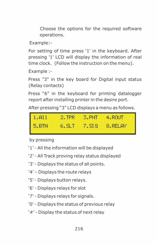
216
Choose the options for the required software
operations.
Example:-
For setting of time press '1' in the keyboard. After
pressing '1' LCD will display the information of real
time clock. (Follow the instruction on the menu).
Example :-
Press "3" in the key board for Digital input status
(Relay contacts)
Press “6” in the keyboard for printing datalogger
report after installing printer in the desire port.
After pressing "3" LCD displays a menu as follows.
by pressing
‘1’ - All the information will be displayed
‘2’ - All Track proving relay status displayed
‘3’ - Displays the status of all points.
‘4’ – Displays the route relays
‘5’ - Displays button relays.
‘6’ - Displays relays for slot
‘7’ - Displays relays for signals.
‘0’ - Displays the status of previous relay
‘#’ - Display the status of next relay

217
Note: If the user has not selected any type and
pressing ' 0 ' will show the status of relays
considering default type ALL.
1113. Print Datalogger Report :
• Connect printer port with printer. Switch on the
supply to the printer.
• Press "6" option in the initial menu appear after
pressing.
Now LCD displays as follow:
If the printer is "OFF LINE" mode, the display will be
as shown above. If the printer is in "ON LINE" mode
then the display will be as below :-
If you select - User mode by pressing "1" LCD
displays as below
You can enter the from date/month/year and to
Date/Month/Year and time, for getting the status of
input for the selected time period.
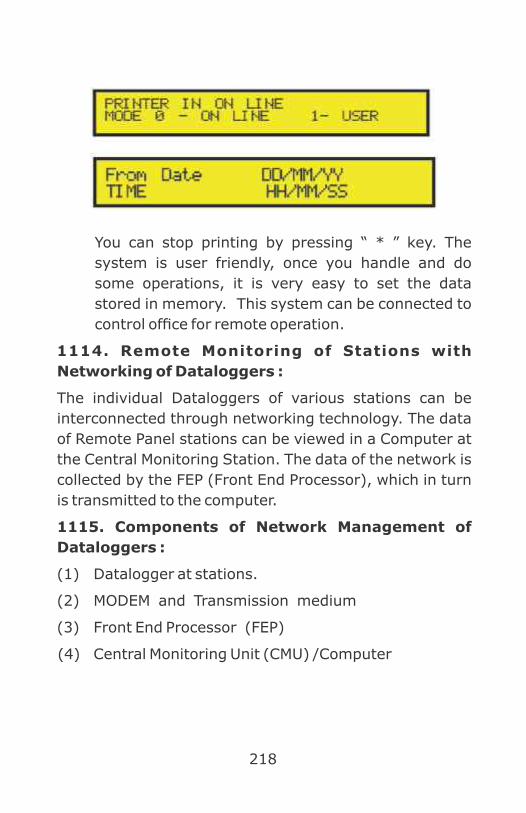
218
You can stop printing by pressing “ * ” key. The
system is user friendly, once you handle and do
some operations, it is very easy to set the data
stored in memory. This system can be connected to
control office for remote operation.
1114. Remote Monitoring of Stations with
Networking of Dataloggers :
The individual Dataloggers of various stations can be
interconnected through networking technology. The data
of Remote Panel stations can be viewed in a Computer at
the Central Monitoring Station. The data of the network is
collected by the FEP (Front End Processor), which in turn
is transmitted to the computer.
1115. Components of Network Management of
Dataloggers :
(1) Datalogger at stations.
(2) MODEM and Transmission medium
(3) Front End Processor (FEP)
(4) Central Monitoring Unit (CMU) /Computer

219
Blo
ck D
iagra
m O
f N
etw
ork
Managem
ent
Of D
ata
loggers

220
CHAPTER 12
Know Your Panel

221
222
Bibliography
1. IRPWM
2. IRSEM- Chapter letter no. XV -STS/E/Cable Planning
and Laying Cable Practices laying. Dt 31.10.2011 -
guidelines for Signalling cable laying
3. Glued Joint Manual 1998 upto date.
4. IRSOD
5. CAMTECH Publication
6. RDSO Publication
7. IRISET lecture notes
8. Guidelines on Signaling Cable Laying by RDSO vide
RDSO/SI/G/2010 VIA Dt. 04.02.2014.
9. Policy on cable laying for cable route is circulated by
RDSO vide letter No.2004/SIG/G/7 dt. 17/12/2004
& 13/12/2005
10. Chapter XXII of Signal Engineering Manual-II.
11. JPO No. 1/Sig/2004 issued by AM(Sig), AM(Tele), AM
(Electrical) and AM (Works) for undertaking digging
work in the vicinity of underground S&T and
Electrical Cables
12. Burring of S&T Cables due to fire- Preventive
Measures RB letter no.2011/SIG/SF/1/Pt
Ot.23.02.2012
13. Shifting of starter signal ahead of boundary of track
circuit vide Railway board letter no.2012/Safety
(A&R)/19/5 Dt.13.06.2013

223
14. Joint Inspection of Points and Crossings by
SSE/PWay & SSE/Sig. vide SG.85/1 Dt. 15-12-2016
Southern Railway
15. Central Railway letter no.W.827/T-II/Vol.XVII Dt.
24.11.2011 for laying of glued joint.
16. Review of Station Working Rules vide 2000/
Safety/(A&R)/19/36 Dt. 07.11.2012
17. Increase of speed of passenger trains to 160 kmph
vide 2013/Infra/12/43 dt. 05.9.2014
18. Interlocking of LG Gates. (RB letter No.77/W-
3/SG/LX/2 dt. 16.3.79)


For any suggestions, errors etc, please contact on Email : [email protected]