Novel Differential Mechanism Enabling Two DOF from a ... · is held fixed by the brake, ... system...
6
1 Abstract— There will always be a drive to reduce the complexity, weight, and cost of mobile platforms while increasing their inherent capabilities. This paper presents a novel method of increasing the range of achievable grasp configurations of a mechatronic hand controlled by a single actuator. By utilizing the entire actuator space, the hand is able to perform four grasp types (lateral, precision, precision/power, and power) with a single input resulting in a potentially lighter and simpler hand design. We demonstrate this strategy in a prototype hand that is evaluated to determine the benefit of this method over the addition of a second actuator. Results show a decrease in weight but a 0.8 sec transition time between grasp types with the proposed method. The prototype hand can be controlled by a single EMG signal that can command a change in grasp type or an opening/closing of the hand. We discuss the potential of this mechanism to improve prosthetic hand design as compared to current myoelectric systems. I. INTRODUCTION ITH the development of highly articulated robot hands, there is a fundamental problem associated with the packaging and control of numerous actuators to perform a wide range of functions. Specifically in the field of robotics and prosthetics, there is a tradeoff between the number of independent motions and the weight and complexity of the entire device. Even if the device is able to control 22 independent degrees of freedom (DOF), as is the case for human hand motion, the packaging of such a system would be too large and heavy for practical use. Within the field of prosthetic hand design, the weight of the device remains one of the most distinguishing factors that limit adoption by amputee users. A survey of myoelectric prosthesis users found that users rated the weight of the device as a 70 on a scale of 0 (not important) to 100 (most important) with regards to the design priorities of prosthetic hands [1]. One key means of reducing the weight of the device is to reduce the number of actuators used within the hand. DC motors and their associated transmission mechanisms make up a large amount of the total weight of highly dexterous robotic hands. A study of hand motion [2,3] has shown that most common activities can be achieved with a finite set of hand grasping motions. Therefore, hand designers should evaluate the tradeoff between additional hand functions with the added weight and packaging constraints of additional actuators. This tradeoff has led to the study of the principle components of grasping in which each additional actuator controls a linear subset of all DOF and thus best utilizes the benefit of additional actuators. A practical implementation of the grasp principle components was developed in [4]. One observation of the major differences in the grasp types used for acquisition and holding of typical objects is the positioning of the thumb prior to making the closing motion of the hand [2] and the timing of when the fingers are closed in relation to the movement of the thumb. The i- Limb® and Bebionic® hands both utilize an abduction/adduction movement of the thumb to change grasp types [5]. In these commercial prosthetic hands, the thumb motion is done by locking the thumb manually into different predefined abduction/adduction position. In this paper, we describe a novel actuation mechanism scheme that allows two independent DOF to be controlled by a single actuator. The approach involves using one half of the actuator space (e.g. the “positive” rotation from zero) to control the opening/closing of the hand, and the other half (the “negative” rotation from zero) to move the thumb to select the grasp type. Since the overall flexion/extension of all the fingers of the hand, and the thumb abduction/adduction movements were considered the most important in achieving multiple grasp types, we have Novel Differential Mechanism Enabling Two DOF from a Single Actuator: Application to a Prosthetic Hand Joseph T. Belter and Aaron M. Dollar Department of Mechanical Engineering and Materials Science Yale University New Haven, CT 06511, USA [email protected], [email protected] W Fig. 1. The prototype hand utilizes a single motor to open/close the hand as well as switch grasp types to perform lateral, precision, and power grasps. 2013 IEEE International Conference on Rehabilitation Robotics June 24-26, 2013 Seattle, Washington USA 978-1-4673-6024-1/13/$31.00 ©2013 IEEE
-
Upload
phungthuan -
Category
Documents
-
view
218 -
download
0
Transcript of Novel Differential Mechanism Enabling Two DOF from a ... · is held fixed by the brake, ... system...
1
Abstract— There will always be a drive to reduce the
complexity, weight, and cost of mobile platforms while
increasing their inherent capabilities. This paper presents a
novel method of increasing the range of achievable grasp
configurations of a mechatronic hand controlled by a single
actuator. By utilizing the entire actuator space, the hand is able
to perform four grasp types (lateral, precision, precision/power,
and power) with a single input resulting in a potentially lighter
and simpler hand design. We demonstrate this strategy in a
prototype hand that is evaluated to determine the benefit of this
method over the addition of a second actuator. Results show a
decrease in weight but a 0.8 sec transition time between grasp
types with the proposed method. The prototype hand can be
controlled by a single EMG signal that can command a change
in grasp type or an opening/closing of the hand. We discuss the
potential of this mechanism to improve prosthetic hand design
as compared to current myoelectric systems.
I. INTRODUCTION
ITH the development of highly articulated robot hands,
there is a fundamental problem associated with the
packaging and control of numerous actuators to perform a
wide range of functions. Specifically in the field of robotics
and prosthetics, there is a tradeoff between the number of
independent motions and the weight and complexity of the
entire device. Even if the device is able to control 22
independent degrees of freedom (DOF), as is the case for
human hand motion, the packaging of such a system would
be too large and heavy for practical use. Within the field of
prosthetic hand design, the weight of the device remains one
of the most distinguishing factors that limit adoption by
amputee users. A survey of myoelectric prosthesis users
found that users rated the weight of the device as a 70 on a
scale of 0 (not important) to 100 (most important) with
regards to the design priorities of prosthetic hands [1]. One
key means of reducing the weight of the device is to reduce
the number of actuators used within the hand. DC motors
and their associated transmission mechanisms make up a
large amount of the total weight of highly dexterous robotic
hands.
A study of hand motion [2,3] has shown that most
common activities can be achieved with a finite set of hand
grasping motions. Therefore, hand designers should evaluate
the tradeoff between additional hand functions with the
added weight and packaging constraints of additional
actuators. This tradeoff has led to the study of the principle
components of grasping in which each additional actuator
controls a linear subset of all DOF and thus best utilizes the
benefit of additional actuators. A practical implementation
of the grasp principle components was developed in [4].
One observation of the major differences in the grasp
types used for acquisition and holding of typical objects is
the positioning of the thumb prior to making the closing
motion of the hand [2] and the timing of when the fingers
are closed in relation to the movement of the thumb. The i-
Limb® and Bebionic® hands both utilize an
abduction/adduction movement of the thumb to change
grasp types [5]. In these commercial prosthetic hands, the
thumb motion is done by locking the thumb manually into
different predefined abduction/adduction position.
In this paper, we describe a novel actuation mechanism
scheme that allows two independent DOF to be controlled
by a single actuator. The approach involves using one half of
the actuator space (e.g. the “positive” rotation from zero) to
control the opening/closing of the hand, and the other half
(the “negative” rotation from zero) to move the thumb to
select the grasp type. Since the overall flexion/extension of
all the fingers of the hand, and the thumb
abduction/adduction movements were considered the most
important in achieving multiple grasp types, we have
Novel Differential Mechanism Enabling Two
DOF from a Single Actuator: Application to a
Prosthetic Hand Joseph T. Belter and Aaron M. Dollar
Department of Mechanical Engineering and Materials Science
Yale University
New Haven, CT 06511, USA
[email protected], [email protected]
W
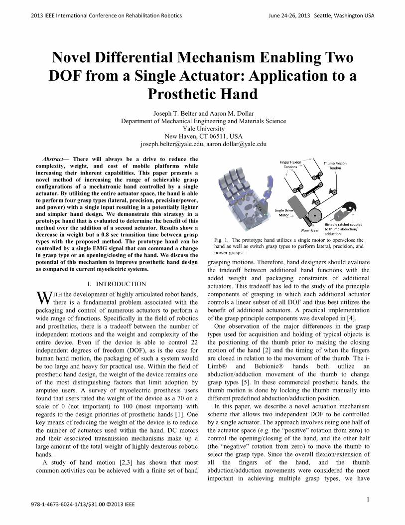
Fig. 1. The prototype hand utilizes a single motor to open/close the
hand as well as switch grasp types to perform lateral, precision, and
power grasps.
2013 IEEE International Conference on Rehabilitation Robotics June 24-26, 2013 Seattle, Washington USA
978-1-4673-6024-1/13/$31.00 ©2013 IEEE

2
coupled these motions to a single actuator. Thus, we allow
the hand to switch between four common grasp
configurations without manual input from the user. It also
allows the design to be packaged completely within the palm
of a 50th
percentile male size hand and reduces the weight
and size of the device compared to a two-actuator system.
We begin the paper by reviewing previously described
mechanisms providing similar functionality (section II).
Next, we present the new design and show its
implementation in a prototype hand. Finally, we discuss
limitations of the approach and how this strategy could help
improve practical prosthetic hands (section V).
II. EXAMPLES OF EXISTING SYSTEMS
In this section we present a brief review of systems that
focus on reducing the need for additional actuators to control
a wide range of functions.
A. Underactuated Mechanisms
A common technique utilized in robotic hands is the use
of underactuated coupling mechanisms. Underactuated
mechanisms, as studied by [6,7] and others, are systems with
more DOF than the number of actuators, but with each of
those DOF passively coupled to the actuator. Although there
is no direct control of each DOF, these systems control the
sum of movement across all connected outputs. Examples of
underactuated systems include floating pulley trees,
differential gearing, and wiffle trees [7, 8]. Since the force
distribution is determined by the coupling method and not a
direct position coupling, external forces have an influence on
the positions of the joints. This makes the technique
attractive for use in grasping where the fingers are able to
conform to an irregular shaped object.
B. Force Directing Actuation Systems
Another type of system is based on the idea of using a
single large input that is coupled to all the outputs through
individually controlled transmissions. The Cobot concept,
developed at Northwestern University, uses multiple
infinitely variable transmissions (IVT) that are each
connected to a single drive element [9]. By independently
changing the coupling ratio between the drive element and
the output for each degree of freedom, any desired motion of
the outputs can be achieved simultaneously. These systems
have been demonstrated with six outputs controlling a 6-
DOF Stewart Platform [9]. The advantage is that the main
drive element can provide all of the power to a single output
or split the power between all six outputs. If a system was
developed with six individual motors of equivalent total
power output, the system would be only be able to exert 1/6th
of the power to a single output as compared to the Cobot
architecture. Also, the weight of the 6-motor system would
be larger than the weight of the Cobot system. The Cobot
architecture has also claimed to provide power and weight
savings when used in advanced prosthetic hands [10].
Other robotic hand designs use one main drive element
connected to numerous outputs with a large underactuated
differential mechanism. The differential mechanism
distributes force equally across all the outputs. When not in
contact with an object, the fingers of these hands will close
in a fixed path. The designers then implement small
electronic brakes on all the outputs. When one of the outputs
is held fixed by the brake, the input forces are then split
between the remaining free-spinning outputs [11]. Each
individual output can be controlled by driving the input with
all other outputs held fixed with the brake.
C. Gait Based Actuation Systems
One final method used in robotic hands is to couple
multiple functions through a specific cycle of motion or
“gait”. An example of this type of system is seen in the KNU
Hand [12] which incorporates a Geneva wheel [13], to
Fig. 2. This schematic diagram shows the method of controlling the position of output 1 and output 2 using the position of a single motor and a bistable ratchet. a) In the zero motor position the drive tendons to both outputs are tight. b) As the motor pulley turns clockwise, the motor pulls on
a toothed plate to the desired position of Output 1. c) Output 2 is then controlled by moving the motor pulley in the counter-clockwise direction. d)
To reset the position of the toothed plate, the plate is move to it’s extreme position where the ratchet is pushed up to a stable position away from the
plate teeth. When the toothed plate moved back to the zero position, it pulls the ratchet pawl back into contact with the teeth.

3
couple the opening/closing of the thumb to the thumb
abduction/adduction. The motion of the KNU thumb can be
described as a single path that contains both thumb
flexion/extension and abduction/adduction. Therefore, there
is a direct mapping of input to output state. One of the key
problems with moving the thumb along a single path of
motion is that in order to change the thumb abduction
position, the thumb must flex and extend completely in all
abduction states leading up to the desired position.
III. NOVEL THUMB ACTUATION METHOD
A. Conceptual Design
The proposed thumbs actuation system is based on using a
clockwise movement of the motor to affect one output while
a counter-clockwise movement affects another output. A
schematic diagram of the system is shown in Fig. 2. The
system consists of two outputs that can be controlled with a
single motor input position. As seen in Fig. 2 (a), when the
motor is in the zero position, the drive tendons to the two
outputs are tight. Any movement of the motor clockwise,
shown in Fig. 2 (b) causes the toothed plate, (here serving as
the position of Output 1) to move to the right. During this
motion, a ratchet pawl is engaged in a set of teeth that locks
the toothed plate in the most positive position. To affect
Output 2, the motor is turned counterclockwise, as shown in
Fig. 2 (c). Here the tendon connecting the motor and toothed
plate becomes completely slack while the tendon connected
to Output 2 is tight. In this configuration the movement of
the motor corresponds with the motion of Output 2. To reset
the position of Output 1, the toothed plate is moved to its
maximum travel position through a clockwise motion of the
motor. At this point a protrusion on the toothed plate pushes
up on the ratchet pawl. The spring holding the ratchet pawl
goes over center, (to the other side of the pivot point) and
holds the ratchet up against a hard-stop, away from the teeth
of the plate. The ratchet pawl is then pulled back against the
teeth by a ramp at the front of the plate. Since the ratchet
pawl is held by the spring in two stable positions, it is
referred to as a bistable ratchet. This is the key feature that
allows both outputs to be controlled with the same motor.
B. Implementation in Robotic Hand
To implement the actuation scheme in a hand, we first
needed to make the two outputs of the system described in
Fig. 2 represent the opening/closing of the fingers and the
change in the thumb abduction/adduction angle. Fig. 3
illustrates how this was achieved within the architecture of
the hand.
The motion described as Output 2 in Fig. 2, is replaced
with the drive tendons that control the flexion of all the
fingers. The index, middle, ring, and little fingers are
connected through an underactuated floating pulley tree.
The underactuated coupling lets the fingers passively adapt
to the shape of objects in the grasp. The thumb flexion
tendon is directly coupled to the first drive tendon of the
pulley tree and thus not included in the differential.
The motion described as Output 1 in Fig. 2, controls the
abduction/adduction position of the thumb. The rotational
position of the thumb determines the type of grasp the hand
will perform. One key observation when attempting to flex
all fingers of the hand with a single actuation, was the
difference in the thumb closing timing relative to the other
fingers in the different grasp configurations. For example,
when performing a lateral grasp, the thumb must wait until
the fingers form a complete fist before closing to apply
pressure to the side of the index finger. When performing a
precision grasp, the thumb must close in sync with the index
finger so they meet in the center. Fig. 3 shows a way to
accommodate for the difference in thumb flexion timing in
the four grasp configurations of the prototype hand. As the
thumb abduction/adduction position is changed, an
additional pulley interferes with the path of the thumb
flexion cable. This tightens the thumb flexion cable when
the thumb is moved toward a power grasp position. The size
and spacing of the pulleys was modified until the desired
effect was achieved for all grasp types.
Fig. 3. Schematic of cable routing system used in the prototype hand. The thumb abduction/adduction position influences the relationship
between the flexion of the thumb and four fingers by removing the
slack in the thumb flexion cable with more adduction of the thumb.
4
IV. EVALUATION OF PROTOTYPE HAND
A prototype hand was build to test the benefits of the
proposed coupling strategy described in Sec. III.
A. General Construction
The palm of the hand was sized base on the 50% male
right hand. It consists of two acrylic plates that make up the
front and back of the palm. All actuation components are
housed within the palm of the hand. The single DC motor,
detailed in Table 1, is mounted vertically along the inside of
the palm. It is connect through a set of worm gears to the
motor drive pulley. The worm gear makes the system non-
backdrivable and therefore able to maintain grasp force
without continued current draw to the motor. The motor and
transmission can be seen on the left side of the palm in Fig.
4 (far left).
The fingers of the hand are made through shape deposition
manufacturing out of three types of polyurethane resin as
detailed in [3]. Each finger has a proximal and distal flexure
joint with a single actuation tendon spanning both joints.
The thumb is connect to the palm through a Delrin® base
(seen as the black block at the base of the thumb in Fig. 4,
far left) which pivots on an abduction/adduction axis that is
slightly angled toward the base of the middle finger. A
rotational version of the linear bistable ratchet and pawl
mechanism shown in Fig. 2 and 3 is attached to the bottom
of the Delrin ® base and controls the abduction angle of the
thumb. The rotational ratchet system, illustrated in Fig. 5,
has four discrete abduction positions, corresponding to the
desired thumb position for each grasp type.
The pulleys of the underactuated pulley tree (which drives
the index, middle, ring, and little fingers) are machined from
aluminum and have enough travel to allow the fingers to
adapt to various object shapes. Table 1 shows the general
specifications of the prototype hand. The grasp force and
speed measurements were performed with 12V supply
voltage.
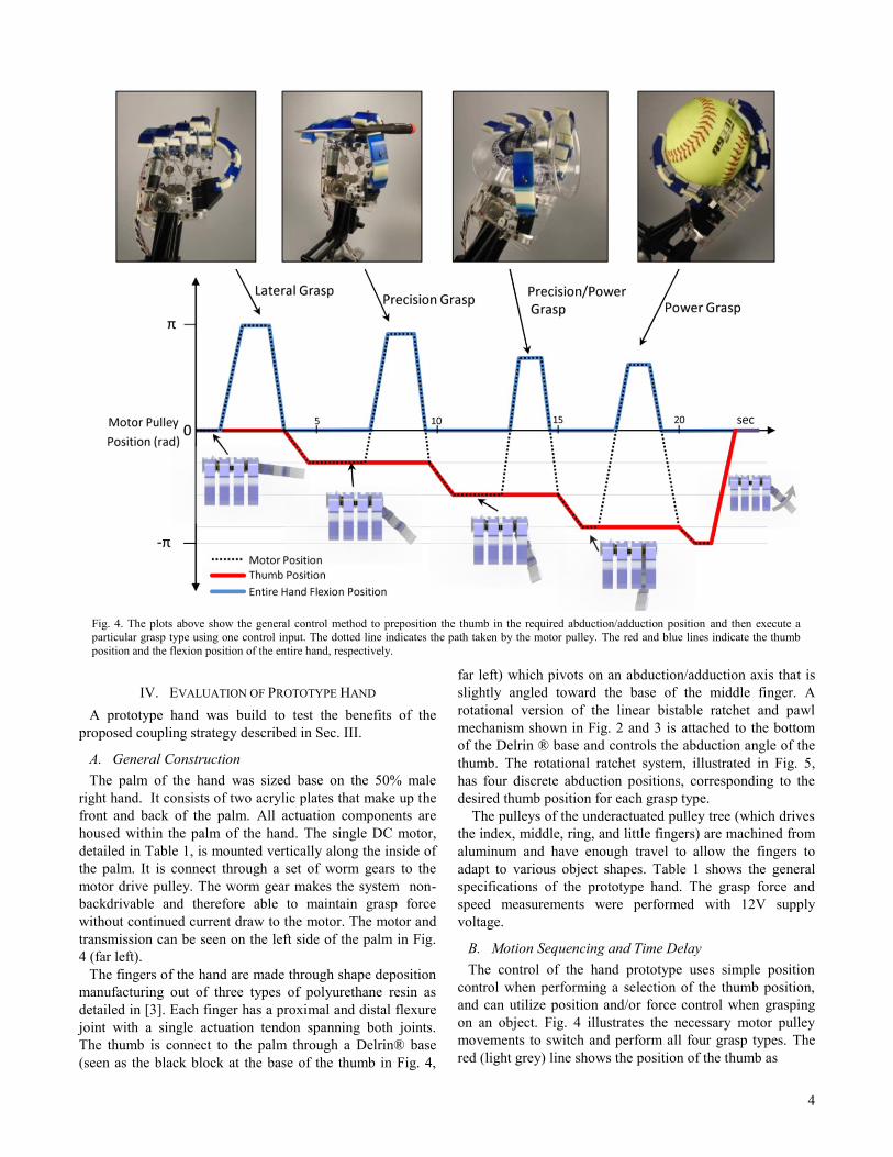
B. Motion Sequencing and Time Delay
The control of the hand prototype uses simple position
control when performing a selection of the thumb position,
and can utilize position and/or force control when grasping
on an object. Fig. 4 illustrates the necessary motor pulley
movements to switch and perform all four grasp types. The
red (light grey) line shows the position of the thumb as
Fig. 4. The plots above show the general control method to preposition the thumb in the required abduction/adduction position and then execute a
particular grasp type using one control input. The dotted line indicates the path taken by the motor pulley. The red and blue lines indicate the thumb
position and the flexion position of the entire hand, respectively.

5
Table I : Single Actuator Hand Specifications
Motor 4-Watt Maxon RE-max 17
Transmission 19:1 Planetary with 22:1
Worm gear reduction
Degrees of Freedom 11
Coupling Method Floating Pulley Tree
Weight 350 grams*
Control Method Off-board single-site EMG
Manufacturing Method SDM Fingers with Acrylic palm
Grasp Force 5.1 N (Power Grasp)
4.7 N (Lateral Grasp)
Grasp Speed (Full Power Grasp) 0.9 sec
Grasp Type Transition Speed 0.8 sec
1.2 sec (power to lateral)
*without battery or control hardware
related to the position of the motor (indicated by a black
dotted line). The solid blue (dark grey) line shows the
flexion position of all the fingers. The graph shows a
sequence of performing each of the four grasp types in
succession and returning the thumb to the lateral grasp
position. It should be noted that due to the limitations of the
actuation method there is a small time delay associated with
switching between grasp types. This time delay is present
even if the pretension length is changed since the hand must
open completely before switching grasp types.
C. User Control of Grasp Type and Closing
To represent how an amputee may use this type of system
we controlled both the transition from one grasp to the next
and the closing\opening of the hand through a single EMG
signal. The signal was taken from a single site on the
forearm and a typical signal threshold was established. If the
signal was above the threshold for greater than 200 msec, a
closing of the hand was initiated until the signal was
terminated. Any “twitch”, defined as an EMG signal above
the threshold for less than 200 msec, caused the hand to
either open the grasp to the zero position, or move the thumb
abduction/adduction corresponding to the next grasp type. If
a “twitch” signal was received while in a power grasp
position, the thumb was returned to the lateral grasp
location.
V. DISCUSSION
The prototype single actuator hand demonstrated the
practical implementation of the actuation scheme presented
in Fig. 2 & 3 to reduce the number of actuators required in a
functional robotic hand.
The hand was able to show a similar function to a hand
with a separate actuator controlling the abduction/adduction
position of the thumb. The weight of the components alone
associated with the thumb abduction/adduction movement
was approximately 25 grams. This included the added
pulleys and the bi-stable ratchet system at the base of the
thumb. The added weight associated with placing a second
DC motor (same as in the prototype) at the base of the
thumb is estimated to be 60 grams based on the weight of
the motor and required transmission elements. Therefore,
based on the weight of the necessary components, the
strategy presented in this paper could account for a 35 gram
improvement in the weight of the device (assuming similar
overall hand construction). This 10% improvement in total
device weight (not including the batteries and control
system) must be compared to the reduced function as
compared to a similar hand with two actuators.
One limitation of the system presented is that the thumb
abduction/adduction position can only be altered while the
hand is open. This prevents the hand from performing any
form of in-hand manipulations that requires simultaneous
movements. In the case of prosthetic terminal devices, in-
hand manipulation is not necessary which indicates that the
lack of simultaneous motion would only be detrimental to
those wishing to use this system for robotic hand
applications.
There is also a time-delay associated with switching
between grasp types due to the nature of the actuation
method. Fig. 5 illustrates a state-space representation of the
hand. This mapping can be used to illustrate how to achieve
the required grasp type. Unlike a hand with fixed coupling
(e.g. [8]), the system does not have a single variable that can
describe the entire state of the system. The small images
show the position of the rotary bistable ratchet at each state
of the system which correspond to the different grasp types.
From each thumb position, the user can either perform that
particular grasp type associated with that thumb position, or
move to the next thumb position in the sequence. The hand
system requires 0.8 sec to move the abduction angle of the
thumb and return to the motor pulley zero position, ready to
perform the next grasp type. To transition from a precision
grasp to a lateral grasp can take as much as 2.8 sec. This
delay in the ability to perform the desired grasp type may
prove too long for the system to be used in a prosthetic hand.
VI. CONCLUSION
In this paper, we showed a marginal weight benefit of a
proposed coupling strategy to enable a prototype hand to
perform four grasp types with a single motor. Obvious
limitations were identified including the lack of
Fig. 5. State space representation of the control architecture for the
single actuator prototype hand. The bistable ratchet state is also shown at each grasp type and reset sequence. The rotation of the green ratchet
plate represents the abduction/adduction angle of the thumb.
6
simultaneous motion of the two outputs as well as a long
time delay associated with switching between grasp types.
Since weight is known to be an important factor in the
adoption of terminal devices, this mechanical system could
help in the development of better, lighter, terminal devices.
ACKNOWLEDGMENTS
The authors would like to thank the Gustavus and Louise
Pfeiffer Research Foundation for their support of this work.
REFERENCES
1. E. Biddiss, D. Beaton, and T. Chau, “Consumer design priorities
for upper limb prosthetics,” Disabilities and Rehabilitation: Assistive Technology, , pp. 346-357, November 2007
2. M.R. Cutkosky, “On Grasp Choice, Grasp Models, and the
Design of Hands for Manufacturing Tasks,” IEEE Trans. Robot.
Automat., 5(3), (1989) pp. 269–279
3. J. Z. Zheng, S. De La Rosa, and A. M. Dollar “An
Investigation of Grasp Type and Frequency in Daily Household and Machine Shop Tasks,” Proceedings of ICRA 2011 IEEE,
Shanghai, China, May 9-13, 2011
4. C. Y. Brown, and H. H. Asada, “Inter-Finger Coodination and Postural Synergies in Robot Hands via Mechanical
Implementation of Principal Components Analysis,” Proceedings of the International Conference of Intelligent Robots and
Systems, 2007, pp2877-2882.
5. J.T. Belter, J. Segil, A.M. Dollar, and R.F. Weir “The Mechanical Design and Performance Specifications of
Anthropomorphic Prosthetic Hands” Journal of Rehabilitation
Research and Development, 2013 (in press) 6. A. M. Dollar and R. D. Howe, "The Highly Adaptive SDM
Hand: Design and Performance Evaluation," International
Journal of Robotics Research, Vol. 29, No. 5, pp 585-597, 2010. 7. L. Birglen, C. Gosselin, T. Laliberté, “Underactuated Robotic
Hands,” Quebec, Canada © 2010 Springer-Verlag Berlin
Heidelberg 8. M. Baril, T. Laliberté, F. Guaw, and C. Gosselin, "Static
Analysis of Single-Input/Multiple-Output Tendon-Driven
Underactuated Mechanism for Robotic Hands”, IDETC 2010, August 15-18, 2010, pp. 155-164
9. E. L. Fauling, J. E. Colgate, M A. Peshkin, “Control and
Performance of the Rotation-to-linear Cobotic Transmission,” Symposium on Haptic Interfaces for Virtual Environmental and
Teleoperator Systems 2006, pp. 103-108.
10. E. L. Fauling, J. E. Colgate, M A. Peshkin, “Cobot Architecture for Prosthetics,” Proceedings of IEEE IMBS annual
international conference 2006, SaD08.1, pp. 5635-5637.
11. W. J. Chen and M. Xie, “On the Design of a Novel Dexterous Hand”, The 9th International Conference on Advanced
Robotics, Tokyo/Japan (1999), pp. 61-65.
12. J. Chu, D. Jung, and Y. Lee, “Design and Control of a Mutlifunction Myoelectric Hand with New Adaptive Grasping
and Self-locking Mechanisms,” IEEE International Conference
on Robotics and Automation 2008, pp. 743-748. 13. N. Sclater, N.P. Chronis, “Mechanisms and Mechanical Devices
Sourcebook” 4th edition, McGraw-Hill, 2007