Nov 11, 2004CS573: Network Protocols and Standards1 IP Routing: OSPF Network Protocols and Standards...
25
Nov 11, 2004 CS573: Network Protocols and Sta ndards 1 IP Routing: OSPF Network Protocols and Standards Autumn 2004-2005
-
date post
19-Dec-2015 -
Category
Documents
-
view
216 -
download
0
Transcript of Nov 11, 2004CS573: Network Protocols and Standards1 IP Routing: OSPF Network Protocols and Standards...
Nov 11, 2004 CS573: Network Protocols and Standards
1
IP Routing: OSPF
Network Protocols and Standards
Autumn 2004-2005

Nov 11, 2004 CS573: Network Protocols and Standards 2
Issues Design of OSPF
Separating hosts and routers Broadcast networks (Ethernet, FDDI,
…) Non-broadcast networks (ATM, X.25,
…) Splitting very large networks into
areas

Nov 11, 2004 CS573: Network Protocols and Standards 3
Separating Hosts and Routers
Instead of link-state records for hosts:R-H1R-H2R-H3
Use simplification based on subnet model- One link between the router and the subnet: “link to stub network”- Identified by its subnet number
R H1H2
H3

Nov 11, 2004 CS573: Network Protocols and Standards 4
Stub Networks
Multiaccess/broadcast stub network Single router attached to the network N is network IP address and associated mask
N
RTRT
N
Graph Representation

Nov 11, 2004 CS573: Network Protocols and Standards 5
Point to Point Networks
Unnumbered point-to-point network Interfaces to point-to-point network not
assigned IP addresses
RT1 RT1 RT2
Graph Representation
RT2

Nov 11, 2004 CS573: Network Protocols and Standards 6
Point to Point Networks
Numbered point-to-point network Ia and Ib are interface IP addresses
RT1 RT1 RT2
Graph Representation
RT2Ia Ib
Ia Ib

Nov 11, 2004 CS573: Network Protocols and Standards 7
Stub Networks
Host directly attached to a router Host route Mask is 0xFFFF FFFF (255.255.255.255)
Host
RTRT
Host
Graph Representation

Nov 11, 2004 CS573: Network Protocols and Standards 8
Broadcast Networks Such networks characterized by:
Full connectivity Broadcast capability
Issues (when N routers coexist on a broadcast network):
# Adjacencies: N(N-1)/2 Each router would advertise:
N-1 links to other routers One link to the subnetwork
Solution: reduce number of adjacencies to N One router is designated through election Election of the designated router is through “Hello
Protocol”

Nov 11, 2004 CS573: Network Protocols and Standards 9
Broadcast Networks Reducing the number of link state
records using designated router Database will include two links per router
One link from router to virtual node Called router link type 2 (transit network) Advertised by the router itself Appropriate metric
Link from virtual node to router Called network link Advertised by designated router Network links have a null metric

Nov 11, 2004 CS573: Network Protocols and Standards 10
Broadcast Networks
RT1
RT2
RT3
RT4
N
RT1 RT2
RT4RT3
Multiaccess/broadcast transit network - 3 or more routers attached to the network

Nov 11, 2004 CS573: Network Protocols and Standards 11
Broadcast Networks Simplifying flooding
A router sends a link state advertisement to the designated router only using 224.0.0.6 “all designated routers” multicast address
If advertisement is new, designated router floods the link state on all its interfaces (including the network on which it is received!) using 224.0.0.5 “all OSPF routers” multicast address
Nov 11, 2004 CS573: Network Protocols and Standards 12
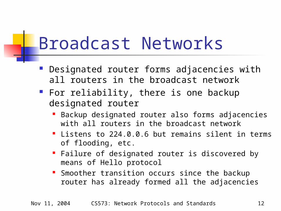
Broadcast Networks Designated router forms adjacencies with all
routers in the broadcast network For reliability, there is one backup designated
router Backup designated router also forms adjacencies with
all routers in the broadcast network Listens to 224.0.0.6 but remains silent in terms of
flooding, etc. Failure of designated router is discovered by means of
Hello protocol Smoother transition occurs since the backup router
has already formed all the adjacencies

Nov 11, 2004 CS573: Network Protocols and Standards 13
Non-broadcast Networks IP over X.25 networks
Popular in Europe in 1980’s IP over ATM
Static configurations Avoid N(N-1)/2 overhead
Use designated router On-demand circuits Permanent circuits are for links between
routers and the “designated router”

Nov 11, 2004 CS573: Network Protocols and Standards 14
Link State DB records Five types of link state records
1. Router link2. Network link3. Summary link (IP network)4. Summary link (to a border router)5. External link
Types 3 and 4 are used when OSPF areas are used

Nov 11, 2004 CS573: Network Protocols and Standards 15
OSPF Router ID Each OSPF router is assigned an
OSPF router ID 32 bit number uniquely identifying
the router within the OSPF domain When the router interfaces have IP
addresses assigned to them, then the OSPF router ID is one of the router’s IP address
Nov 11, 2004 CS573: Network Protocols and Standards 16
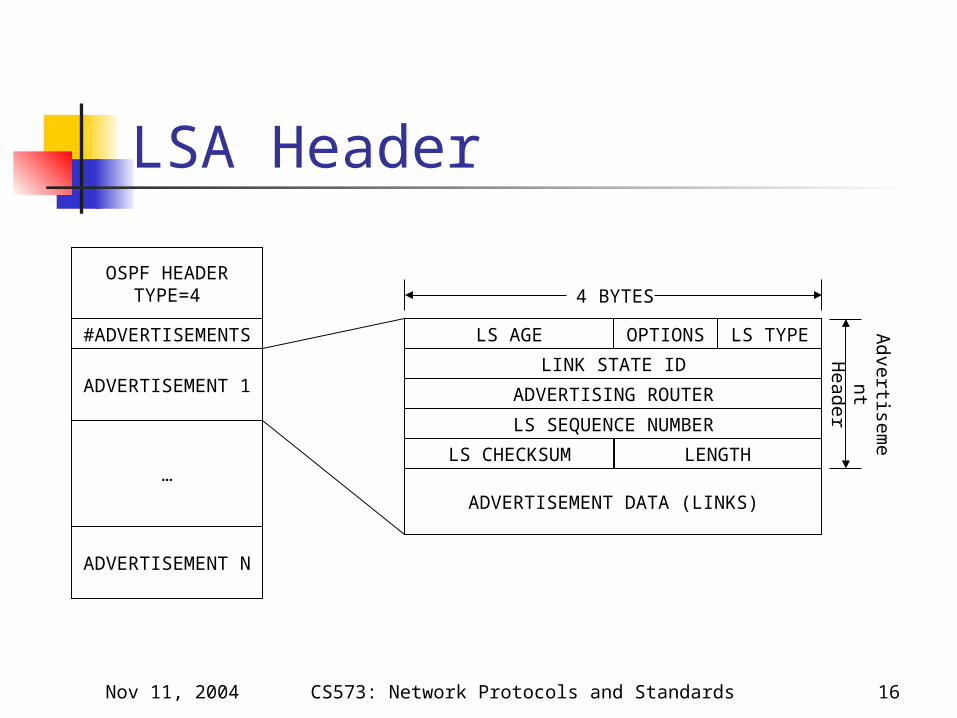
LSA Header
LS AGE LS TYPE
LINK STATE ID
OPTIONS
ADVERTISING ROUTER
LS SEQUENCE NUMBER
LS CHECKSUM LENGTH
ADVERTISEMENT DATA (LINKS)
OSPF HEADERTYPE=4
#ADVERTISEMENTS
ADVERTISEMENT 1
ADVERTISEMENT N
…
4 BYTES
Advertise
men
tH
eader

Nov 11, 2004 CS573: Network Protocols and Standards 17
LSA Header Fields Link state Type
Type of LS record (1, 2, 3, 4, or 5) Link state ID
Chosen by the advertising router Generally an IP address
Sequence Number Identifies one particular advertisement
Checksum Protects header as well as content
Length Total length of the record (including the 20-byte
header)

Nov 11, 2004 CS573: Network Protocols and Standards 18
LSA Header Fields Advertising router
The OSPF ID of the sender Age
16-bit unsigned integer indicating the time in seconds since the link state record was first advertised
Options:
E: used in Hello protocol T: Set when router supports nonzero TOS
Removed from the latest version of the standard (RFC2328)
E TRFC 1583Definition
Type of ServiceExternal Links

Nov 11, 2004 CS573: Network Protocols and Standards 19
Multiple Areas Hierarchical routing
Decreased routing overhead Size of link state DB Duration of route computation Volume of messages exchanged
Split the network into set of independent parts by a backbone
Each area operates like an independent network Database includes only the state of the area’s links Flooding stops at the boundaries Routers compute routes within the area
Cost of routing proportional to the size of the area

Nov 11, 2004 CS573: Network Protocols and Standards 20
Multiple Areas How to glue the network together? Some routers belong to several areas
Typically to the backbone and to one lower-level area
At least one area border router in each area Area border routers
Maintain several link state databases (one for each area to which they belong)
Emit special link state records (summaries) to signal reachability of networks in each area

Nov 11, 2004 CS573: Network Protocols and Standards 21
Stub Areas Areas where there is only one exit point, or the
exit point is not a function of the external destination
Stub area does not need to know the topology of the rest of the AS
All external traffic goes to the exit point Obviously, no AS boundary router can be
internal to the stub areas
R

Nov 11, 2004 CS573: Network Protocols and Standards 22
OSPF Packet Formats OSPF directly over IP, using protocol number 89 OSPF does not explicitly support fragmentation,
but protocol messages can generally be split This should be used rather than IP fragmentation
OSPF packets are sent with an IP TOS of 0 OSPF packets are sent with IP precedence set
to Internetwork control All OSPF packets use the same OSPF header OSPF Multicast addresses (sent with TTL=1)
224.0.0.5: All OSPF routers 224.0.0.6: OSPF designated and backup routers

Nov 11, 2004 CS573: Network Protocols and Standards 23
The Common OSPF Header
VERSION # TYPE PACKET LENGTH
ROUTER ID
AREA ID
AUTHENTICATION
AUTHENTICATION
CHECKSUM AUTYPE

Nov 11, 2004 CS573: Network Protocols and Standards 24
OSPF Header Fields Version #: set to 2 (current version) Type: The OSPF packet type
1. Hello2. Database description3. Link state request4. Link state update5. Link state acknowledgement
Packet length: Number of bytes in the header including the header
Router ID: The IP selected for identifying the router Area ID: The value 0 is reserved for backbone area.
Commonly, an IP address is used to identify the areas Checksum: Computed on the whole OSPF packet,
excluding the 8-octet authentication field

Nov 11, 2004 CS573: Network Protocols and Standards 25
OSPF Header Fields AUTYPE: Identifies the authentication algorithm. Only
three values are identified in the standard itself: 0: No authentication
Exchanges not authenticated Authentication field ignored; can be set to anything
1: Simple authentication “Clear password” type of authentication; all packets must
contain the right value, pre-configured for that area Used to prevent unconfigured routers from joining in
2: Cryptographic authentication Secret key is used to generate a digest of the packet Digest is added at the end of the packet; size not included in
the header 64-bit field is restructured to contain digest size, key ID, and
sequence number (to protect against replay attacks)