
NOTIZIARIO Neutroni e Luce di Sincrotrone - Issue 12 n.1, 2007
49
Vol. 12 n.1 January 2007 - Aut. Trib. Roma n. 124/96 del 22-03-96 - Sped. Abb. Post. 70% Filiale di Roma - C.N.R. p.le A. Moro 7, 00185 Roma NOTIZIARIO Neutroni e Luce di Sincrotrone Rivista del Consiglio Nazionale delle Ricerche ISSN 1592-7822
-
Upload
notiziario-nnls -
Category
Documents
-
view
219 -
download
1
description
Notiziario Neutroni e Luce di Sincrotrone - published by CNR (Publishing and Promotion of Scientific Information) in collaboration with the Faculty of Sciences and the Physics Department of the University of Rome Tor Vergata
Transcript of NOTIZIARIO Neutroni e Luce di Sincrotrone - Issue 12 n.1, 2007

Vol. 12 n. 1 January 2007 - Aut. Trib. Roma n. 124/96 del 22-03-96 - Sped. Abb. Post. 70% Filiale di Roma - C.N.R. p.le A. Moro 7, 00185 Roma
NOTIZIARIONeutroni e Luce di Sincrotrone
Rivista delConsiglio Nazionaledelle Ricerche
ISSN 1592-7822

Cover photo:CAD drawing of BEARexperimental room
published by CNR in collaborationwith the Faculty of Sciences and thePhysics Department of the Universityof Rome “Tor Vergata”.
Vol. 12 n. 1 Gennaio 2007Autorizzazione del Tribunale diRoma n. 124/96 del 22-03-96
EDITOR:
C. Andreani
EXECUTIVE EDITORS:
M. Apice, P. Bosi, D. Catena,P. Giugni
EDITORIAL OFFICE:
L. Avaldi, F. Bruni, S. Imberti,G. Paolucci, R. Triolo, M. Zoppi
EDITORIAL SERVICE AND ADVERTISINGFOR EUROPE AND USA:
P. Casella
CORRESPONDENTS AND FACILITIES:
J. Bellingham (NMI3)M. Bertolo (I3-IA-SFS)A.E. Ekkebus (SNS)
ON LINE VERSION:
V. Buttaro
CONTRIBUTORS TO THIS ISSUE:
M. Capellas EspunyG. Cicognani
GRAPHIC AND PRINTING:
om graficavia Fabrizio Luscino 7300174 RomaFinito di stamparenel mese di Gennaio 2007
PREVIOUS ISSUES ANDEDITORIAL INFORMATION:
Pina CasellaUniversità degli Studidi Roma “Tor Vergata”Tel: +39 06 72594560E-mail: [email protected]
Vol. 12 n. 1 January 2007
NOTIZIARIONeutroni e Luce di Sincrotrone
S U M M A R Y
Rivista delConsiglio Nazionaledelle Ricerche
EDITORIAL NEWSWell Deserved Prize for Jack Carpenter............................ 2I. Anderson
SCIENTIFIC REVIEWSUsing Neutrons to Track Ancient PotteryFiring Technology...................................................................... 3A. Botti, A. Sodo, M.A. Ricci
BEAR: a Bending Magnet for Emission Absorptionand Reflectivity .......................................................................... 8S. Nannarone, A. Giglia, N. Mahne, A. De Luisa, B. Doyle,F. Borgatti, M. Pedio, L. Pasquali, G. Naletto, M.G. Pelizzo,G. Tondello
MUON & NEUTRON & SYNCHROTRON RADIATION NEWS
News from ESRF ..................................................................... 20
News from ILL ........................................................................ 20
News from LCLS..................................................................... 24
News from NCXT ................................................................... 25
News from NMI3 .................................................................... 25
News from SNS........................................................................ 32
SCHOOL AND MEETING REPORTS .................................................. 34
CALENDAR ............................................................................................. 40
CALL FOR PROPOSAL ........................................................................ 42
FACILITIES .............................................................................................. 43
NOTIZIARIONeutroni e Luce di Sincrotrone
www.cnr.it/neutronielucedisincrotrone

EDITORIAL
2
NOTIZIARIO NEUTRONI E LUCE DI SINCROTRONE • Vol. 12 n. 1 January 2007
John Carpenter, better known as Jack to his friends and
colleagues, received the 2006 Clifford G. Shull Prize from
the Neutron Scattering Society of America for his
groundbreaking work developing neutron sources and
instrumentation. The award was presented during the
American Conference on Neutron Scattering, June 18-
22, held in St. Charles, Illinois.
Jack, technical director at Argonne National Laboratory’s
Intense Pulsed Neutron Source, is receiving the award
«for seminal contributions to the development of neu-
tron sources and instrumentation that have had world-
wide impact on neutron scattering across a broad range
of scientific disciplines, culminating in the optimized de-
sign of the Spallation Neutron Source (SNS) at Oak
Ridge». The Clifford G. Shull Prize in Neutron Science is
named in honor of Clifford G. Schull, who shared the
Nobel Prize in physics in 1994 with Bertram Brockhouse
for pioneering developments in neutron science.
Jack, fondly known as the father of the modern Spalla-
tion Neutron Source, played a pivotal role in developing
pulsed neutron sources across the globe, including the
founding of IPNS. He pioneered exploitation of the in-
herent efficiency of the spallation process for producing
neutrons, together with the advantages of pulsed opera-
tion and time-of-flight measurements to study structure
and dynamics of materials. His patented design for the
moderator-reflector combination is at the heart of mod-
ern pulsed neutron sources. Since the IPNS was complet-
ed in 1981, Jack’s competence and skills have been called
on by facilities all over the world for advice on the de-
velopment of spallation sources including the KEK in
Japan, ISIS in the United Kingdom, the Lujan Center at
Los Alamos National Laboratory, Austron in Austria,
J-PARC in Japan, and ESS in Europe.
He was heavily involved in the world’s brightest pulsed
neutron source, the Spallation Neutron Source at Oak
Ridge National Laboratory which produced first neu-
trons in April of this year. He is already working on the
design of the next target station for SNS! Jack’s contribu-
tions to developing pulsed-source instrumentation and
coupling neutron source performance and instrument
design have expanded the use of pulsed neutron sources
to a broad range of scientific endeavors.
Despite his formidable reputation, Jack is known to his
friends and colleagues as a gentleman and a modest,
unassuming man.
Congratulations Jack!
Ian Anderson
Spallation Neutron SourceOak Ridge National Laboratory
Well Deserved Prize for Jack Carpenter
Carla Andreani and John Carpenter, during the Progress in Electron VoltNeutron Spectroscopy Workshop, held at the SNS, ORNL, October 2006.
FOR INFORMATION ON:Conference Announcements and Advertisingfor Europe and US, rates and inserts can befound at:
www.cnr.it/neutronielucedisincrotrone
Pina CasellaTel. +39 06 72594117E-mail: [email protected]

SCIENTIFIC REVIEWS
3
Vol. 12 n. 1 January 2007 • NOTIZIARIO NEUTRONI E LUCE DI SINCROTRONE
Pottery finds are challenging systems; because they com-bine the physical complexity which originates from thecoexistence of an amorphous phase and a crystallinephase in the same sample, with the charming richness ofthe historical information delivered if properly interro-gated. Recent [1] [2] [3] and less recent [4] probing meth-ods have enriched the classical approach of the archaeol-ogists. The archaeometric investigation of the finds cangive access to a quite diverse number of physical-chemi-cal information, including the composition in terms ofelements [5] and minerals [1] [6], the structural proper-ties on the mesoscopic scale [2] up to the macroscopic in-homogeneities [7] [8] [9].The mesoscopic structure investigated through small an-gle neutron scattering (SANS) gives information aboutthe size and surface characteristics of the aggregates ofminerals. These parameters are sensitive to the firingtechnology used in the production process. In the fol-lowing we will show the correlation of these parameterswith the archaeological age of the finds from the excava-tion sites of Miseno an Cuma, and suggest inferences onthe technological choices made over the centuries.The interpretation of the SANS data is also based the si-multaneous knowledge of the mineral phase content ofthe sherds, as probed by Time of Flight Neutron Diffrac-tion (TOF-ND) measurements. During the Roman Age,the harbour of Miseno was the biggest military harbour
of the Mediterranean. After its conversion into a com-mercial harbour, it kept its activity until it was ceded tothe Aghlabids Arabs from Sicily by the Duchy of Naples.It was finally abandoned in the second half of the 9thcentury AD. The early production of ceramics in Misenois characterized by a careful manufacture and a selectivechoice of the shape of the pottery mainly designed forcarriage of foodstuffs [10,11]. This typology tends to dis-appear during the 8th century AD, while other typolo-gies of products made in Miseno continue to exist withcontinuity until the 9th century AD and are known as“broad band ceramic”, after their decoration made byrags or paint brush.The stylistic evaluation suggests a new employment andownership of the facilities, possibly associated to a tech-nological evolution: this is one of the issues that we wantto tackle. It has to be stressed that the samples examinedhere have been found in the same site, called ‘‘LocalitàCudemo’’, where two kilns have been discovered. Thetwo kilns were never operative at the same time, never-theless, the finds belong to the same typology.The second kiln was indeed constructed on top of thefirst one after its voluntary burial. In the area, there is noevidence of other facilities after the 9th century AD. To-gether with Miseno there were other important centres inthe Phlegrean area: Cuma, Pozzuoli and Ischia. In theseplaces production indicators have been found, such as
Using Neutrons to Track Ancient PotteryFiring TechnologyA. Botti, A. Sodo, M.A. Ricci
Dipartimento di Fisica “E. Amaldi”, Università degli Studi di Roma TRE, Via della Vasca Navale 84, 00146 Roma, Italy
s.n. Century Type Technique d Rg s.n. Century Type Technique d Rg
CumaC1 8th-11th comm. SANS 3.28 281 C8 7th-8th comm. ND-SANS 3.46 435C2 7th-8th comm. ND C11 7th-8th comm. SANS 3.70 418C3 7th-8th comm. ND-SANS 3.53 441 C12 6th-8th amph. ND-SANS 3.43 418C4 8th-11th comm. SANS 3.34 551 C15 6th-8th amph. ND-SANS 3.55 370C5 7th-8th comm. ND-SANS 3.54 404 C17 6th-8th amph. ND-SANS 3.45 422MisenoM3 6th-8th amph. ND-SANS 3.75 405 M10 7th-8th comm. ND-SANS 3.34 515M4 6th-8th amph. ND-SANS 3.67 350 M11 11th-13th comm. SANS 3.25 289M6 6th-8th amph. ND-SANS 3.77 376 M12 11th-13th comm. ND-SANS 3.52 523M7 7th-8th comm ND-SANS 3.45 378 M8 7th-8th comm ND-SANS 3.58 481
Table 1: List of the samples from Cuma and Miseno. In the table are reported the dating given by the archaeologists, the typology of use and the diffrac-tion technique used. Rg [Å] and d are radius of gyration and the fractal dimension of aggregates/voids, respectively. Error bars on d and Rg values areof the order of 1% and 10%, respectively.

SCIENTIFIC REVIEWS
4
NOTIZIARIO NEUTRONI E LUCE DI SINCROTRONE • Vol. 12 n. 1 January 2007
kiln rejects, although no kiln itself has ever been local-ized. We have focused our attention on the finds fromCuma which present similar artistic features to thosefrom Miseno. The underlying question is whether theyalso present comparable microscopic characteristics.The archaeological samples are listed in Table 1.They belong to the ceramic production developed in the
south of Italy during the 6th-12th centuries discovered inMiseno (Mn samples) and Cuma (Cn samples).Three different typologies may be distinguished: trans-port amphorae, common ‘‘broad band ceramic’’ and twofragments of common ceramic from the 12th century ADfrom the area of Miseno; the latter samples have indeedbeen dated by the archaeologists after local productionhad ceased [10,11].In the Miseno area there are no clay deposit. In the sametable are reported the diffraction techniques that havebeen used and the dating ranges given by the archaeolo-gists. Small angle neutron scattering measurements havebeen carried out on KWS1 diffractometer, which was op-erative till May 2006 at DIDO reactor of Forschungszen-trum Jülich. Time of flight neutron diffraction experi-ment were performed on ROTAX diffractometer, in-stalled at pulsed neutron source ISIS of Rutherford Ap-pleton Laboratories.The experimental procedure is absolutely non destruc-tive and the samples have been exposed to the beamwithout any specific preparation.A diffraction pattern in the complete Q range exploredby both instruments is shown in fig. 1 as an example.Its best fit according to the Beaucage model [12], con-cerning the SANS part, and by Rietveld analysis [13],for the TOF-ND range, is represented with a red line.
Analysis of the SANS dataThe radius of gyration Rg and the fractal dimension d, asobtained from the fitting procedure, are reported inTable 1.The experimental determination of Rg suffers the biasintroduced by possible multiple scattering effects. Onthe contrary, the most reliable parameter is the fractal di-
mension of the voids/clusters, or equivalently the sloped of the high Q tail. The behaviour of this parameterwith respect to the age of the samples is depicted in fig.2.The abscissas have been calculated as the average valueof the archaeological dating.The samples of Cuma and Miseno share a similar behav-iour: d decreases from higher values for the older sam-ples to lower values for the more recent ones.This can be considered as the history of d: In principle,this history could have no regularity, in the present caseon the contrary it tells us that the more recent ceramicproductions have mesoscopic structures with a roughersurface with respect to the older ones.Using the information coming from the study of refer-ence samples, prepared with different maximum firingtemperature, heating rate and composition, it is possi-ble to state that higher maximum firing temperaturescorresponds to higher values of d [3]: that the smooth-ness of the aggregates surface increases with the firingtemperature.Moreover the dependence of d from the temperature islinear, with a slope that is composition independent. [3]This implies that the maximum firing temperature of thepottery find of Cuma and Miseno has been lowered intime. SANS analysis cannot, however, quantify thechange in maximum firing temperature, when the mi-
Figure 1. Measured (black line) and fitted (red line) SANS and TOF-NDintensity (enlarged in the inset) for M6 sample.
Figure 2: History of the fractal exponent d for samples coming fromMiseno (blue symbols) and Cuma (red symbols). The data relative to the12th century have been reported with a different symbol (triangles), sincethey have been produced at a different kiln.

SCIENTIFIC REVIEWS
5
Vol. 12 n. 1 January 2007 • NOTIZIARIO NEUTRONI E LUCE DI SINCROTRONE
croscopic composition is unknown. The latter informa-tion can be obtained complementing SANS results withmineralogical analysis. [3]In order to justify the differences between the data forsamples M11 and M12, we remind that Miseno kilnceased to produce pottery in the 9th century.This means the 12th century pottery sherds from Misenoarea were likely fired in a different kiln (or kilns) thanthe earlier Miseno samples.
Analysis of the ROTAX dataThe Rietveld analysis included in the model the follow-ing phases: quartz [14], calcite [15], dolomite [16], or-thoclase [17], bytownite [18], muscovite [19], haematite[20] and spinel [21]. The fitted parameters are: phasefractions; d-spacing zero shift; one common Debye-Waller factor for all the minerals except for muscovitewhich was kept constant (u=0.8 Å2) and the lattice pa-rameters for quartz. Once the phase fraction of mus-covite has been removed from the composition, the re-maining phases, compiled in Table 2, have been nor-malized to one. A better comprehension of the clustering and groupingof the samples can be achieved calculating their distancewith respect to a ‘‘mean sample’’, where the weight frac-tion of a phase in the ‘‘mean sample’’ is equal to the av-erage of all the measured weight fractions of that phasein all the sample selected for comparison.In Appendix A the analytical definitions of distance and“mean sample” are described.
In fig. 3 we show the distance plot for Cuma andMiseno samples. They gather in two groups with a con-sistent overlapping and different spread. The samplesof Miseno have been found close to the kiln where theywere produced and this could explain why they grouptogether around -2. As already mentioned, in Misenothere is no clay deposit, so that raw materials must
s.n. Quartz Orthoclase Bytownite q/m Hematite Calcite Dolomite SpinelCumaC2 0.46 0.17 0.31 0.80 0.00 0.06 0.00 0.00C3 0.38 0.16 0.39 0.74 0.01 0.05 0.01 0.00C5 0.38 0.18 0.33 1.16 0.01 0.10 0.00 0.00C8 0.60 0.22 0.00 1.16 0.00 ,0.18 0.00 0.00C12 0.29 0.21 0.39 0.76 0.00 0.10 0.01 0.00C15 0.39 0.16 0.34 0.85 0.01 0.09 0.01 0.00C17 0.44 0.19 0.22 1.85 0.03 0.03 0.02 0.07MisenoM3 0.38 0.21 0.39 1.00 0.02 0.00 0.00 0.00M4 0.39 0.21 0.39 0.72 0.01 0.00 0.00 0.00M6 0.53 0.13 0.21 1.05 0.01 0.12 0.00 0.00M7 0.61 0.14 0.24 1.01 0.01 0.00 0.00 0.00M8 0.43 0.21 0.35 0.50 0.01 0.00 0.00 0.00M10 0.51 0.20 0.20 1.21 0.01 0.08 0.00 0.00M12 0.39 0.23 0.35 1.13 0.02 0.01 0.00 0.00
Table 2: Phase fractions relative abundance for the Cuma and Miseno samples, once the muscovite phase fraction has been removed. The q/m columnrepresents the ratio of the phase fraction of quartz over that one of muscovite.
Figure 3: Distance plot for samples from Miseno (blue bars) and Cuma(red bars).

SCIENTIFIC REVIEWS
6
NOTIZIARIO NEUTRONI E LUCE DI SINCROTRONE • Vol. 12 n. 1 January 2007
have been transported from somewhere else. The dataindicate that the source of the raw clay was keptthroughout the years.The homogeneity of the material in Miseno is confirmedalso by mineralogical and petrographic analysis. On thecontrary, the finds from Cuma have a broader distribu-tion in terms of the distance parameter, i.e. the miner-alogical composition. This suggests that they were pro-duced elsewhere and brought to Cuma (where no kilnhas been found so far), or on the contrary, that the rawmaterials have been imported from more than one place. Following the same procedure of Appendix A, a similarcomparison can be done including samples with knowncomposition and firing conditions. If ancient and refer-ence sherds have close composition, then it is possible touse the d vs T plot of the reference samples as calibrationcurve for the medieval sherds. [3] When this procedure is applied to the finds of Misenoand Cuma, the results of fig. 1 suggests that the maxi-mum firing temperature has been reduced on averagefrom about 900-1000 °C to about 700-800 °C over the peri-od ranging from the 7th century to the 12th century AD.This inference is confirmed by the small amount of cal-cite in the composition of almost all the investigatedsamples [22].The proximity of the two communities of Cuma andMiseno could be the reason for a similar d history, eitherdue to an exchange of goods or due to a technologicalosmosis. Samples from the 12th century deserve a cau-tious consideration, since they cannot belong to the samekiln of Miseno as the others, and because of the smallnumber of experimental determinations; nevertheless,the results on these samples suggest that they have beenproduced in the same region, with similar technology.
Appendix AThe result of the Rietveld analysis is an array of val-ues Aj=[ph1,j;ph2,j;.;phm,j], where j=1...N labels the sam-ple and m=1...kj the mineral phases, which describesboth qualitatively and quantitatively the mineralphase content of each sample. It is then assumed thatsamples manufactured from the same clay, with thesame firing history have the same content in terms ofmineral phases, while different firing histories maydetermine the loss of a particular phase and/or theappearance of a new component.At this stage it may be useful to gather the samples ingroups according to their distance with respect to a‘‘mean sample’’. The latter is defined starting from thearrays of all the N measured samples and is defined tocontain n phases: the mean sample exhibits all the (n≥k)phases which appear at least in one of the real samples.The weight fraction of a phase in the ‘‘mean sample’’ is
equal to the average of all the measured weight fractionsof that phase:
Obviously, some of the n phases which are present in thefictitious ‘‘mean sample’’ may be absent in a real sample.In this case, the weight fraction for the absent n-k phasesin the real sample are set to zero:
The distance of the j-th sample from the ‘‘average’’ isthen defined as:
δ j assumes both positive and negative values, de-pending on the balance between the concentrationsof the different phases.Possible compensation effects arising from positive andnegative terms can be monitored looking at both the to-tal distance and the distance of the individual phases(these comparisons have been done but the correspond-ing plots are not shown in the paper).In the last equation each phase has almost the sameweight, so that a minority phase also contributes to theunambiguous cataloguing of the samples.
AcknowledgmentThe authors would like to acknowledge the ‘‘Soprainten-denza Archeologica di Napoli e Caserta’’, for kindly pro-viding the archaeological samples.These experiments on ROTAX have been performedwithin the Agreement No. 01/901 between CCLRC andCNR, concerning collaboration in scientific research atthe spallation neutron source ISIS and with partial finan-cial support of CNR.
References1. W. Kockelmann A. Kirfel E. Hähnel. Journal of Archaeological Science,
28 213 (2001).2. T. J. Wess, M. Drakopoulos, A. Snigirev, J. Wouters, O. Paris, P. Fratzl,
M. Collins, J. Hiller, K. Nilsen. Archaeometry, 43 117 (2001).

SCIENTIFIC REVIEWS
7
Vol. 12 n. 1 January 2007 • NOTIZIARIO NEUTRONI E LUCE DI SINCROTRONE
3. A. Botti, M. A. Ricci, G. De Rossi, W. Kockelmann, A. Sodo. Journal ofArchaeological Science 33 307 (2006).
4. A. Castellano, M. Martini, E. Sibilia, Elementi di archeometria, Egea,Milano 2002.
5. J. W. Cogswell, H. Neff, M. D. Glacock. Journal of Archaeological Sci-ence, 23 283 (1996); O. S. Rye et al. Archaeometry, 24 59 (1982); P. M.Day, E. Kiriatzi, A. Tsolakidou, V. Kilikoglou. Journal of ArchaeologicalScience, 26 1025 (1999).
6. S. R Simms, J. R. Bright, A. Ugan. Journal of Archaeological Science, 24779 (1997); I. Sondi, D. Slovenec. Archaeometry, 45 251 (2003).
7. S. C. Jordan, C. Schrire, D. Miller. Journal of Archaeological Science, 261327 (1999).
8. M. F. Ownby, C. L. Ownby, E. J. Miksa. Journal of ArchaeologicalScience, 31 31 (2004); R. B. Mason, L. Golombek. Journal of Archaeologi-cal Science, 30 251 (2004).
9. J. Buxeda I Garrigós, R. E. Jones, V. Kilikoglou, S. T. Levi, Y. Maniatis,J. Mitchell, L. Vagnetti, K. A. Wardle, S. Andreou. Archaeometry, 45263 (2003); J. Buxeda I Garrigós, M. A. Cau Ontiveros, V. Kilikoglou.Archaeometry 45 1 (2003); M. Bertelle, S. Calogero, G. Leotta, L.Stievano, R. Salerno, R. Segnan. Journal of Archaeological Science 28 197(2001); A. Pierret, C. J. Moran, L.-M. Bresson. Journal of ArchaeologicalScience 23 419 (1996).
10. G. De Rossi, L’Africa romana XIV, Sassari 2000, Carocci Ed., Roma,2002, pp. 835-846.
11. G. De Rossi, Proceedings of: La ceramica altomedievale in Italia. VCongresso di Archeologia Medievale (CNR, Roma 26-27 November2001), All‘Insegna del Giglio, Firenze, 2004.
12. G. Beaucage, Journal of Applied Crystallography 28 717 (1995).13. H.M. Rietveld, Journal of Applied Crystallography 2 65 (1969).14. J.D. Jorgensen, Journal of Applied Physiology 49 5473 (1978).15. H. Chessin, W.C. Hamilton, B. Post, Acta Crystallographica 18 689
(1965).16. P.L. Althoff, American Mineralogist 62 772 (1977).17. E. Prince, G. Donnay, R.F. Martin, American Mineralogist 58 500
(1973).18. G. Chiari, P. Benna, E. Bruno, Zeitschrift fuer Kristallographie 169
35(1984).19. M. Catti, G. Ferraris, S. Hull, A. Pavese, European Journal of Mineral-
ogy 6 171 (1994).20. R.L. Blake, R.E. Hessevick, T. Zoltai, L.W. Finger, American Mineralo-
gist 51 123 (1966).21. N.G. Zorina, S.S. Kvitka, Kristallografiya 13 703 (1968).22. J. Buxeda, I. Garrigós, H. Mommsen, A. Tsolakidou, Archaeometry 44
187 (2002).

SCIENTIFIC REVIEWS
8
NOTIZIARIO NEUTRONI E LUCE DI SINCROTRONE • Vol. 12 n. 1 January 2007
AbstractThe BEAR (Bending Magnet for Absorption Emissionand Reflectivity) apparatus is presented. The main partsof the apparatus including the transport optics and theexperimental end stations are essentially described. Anumber of scientific results are presented dealing withon going activity at BEAR. They include optical proper-ties of materials, studies of buried interfaces, diffuse in-terface scattering of light and the determination of elec-tronic structure and local geometry of a chemisorbedmolecule on a metal surface.
IntroductionThe BEAR (Bending magnet for emission, absorptionand reflectivity) apparatus [1] is operative at the Elettrastorage ring [2] located in the Science park area of Tri-este, Italy. BEAR is positioned at the 8.1 bending magnetexit of Elettra. The apparatus is conceived to exploit theexperimental possibilities provided by a photon beamof tunable energy with variable ellipticity and selectablehelicity (right circular polarization - RCP, left circularpolarization - LCP) in the study of the interplay of elec-tronic (magnetic included) and local structural proper-ties of solid materials, surfaces and interfaces in the visi-ble-soft X ray range. In fact a number of relevant aspectsare offered by this photon energy range including acomplete insight into the electronic structure giving ac-cess both to full and empty states of bulk [3], surfacesand interfaces [4], collective effects [5] and magneticproperties [6], joint density of states, local- atom selected
– atomic geometry, morphology [7] on a scale rangingfrom Å [8] to tens of nm and surface or interface rough-ness [9]. The BEAR apparatus delivers photons in the 3eV–1600 eV photon energy range. The experimental endstation is based on an ultra high vacuum (UHV) cham-ber which makes possible linear and circular dichroicreflectivity and absorption measurements, diffuse lightscattering, energy resolved visible luminescence, energyintegrated fluorescence and angle resolved photoemis-sion for valence band, core level and local structurestudies. A preparation chamber is connected in UHV tothe experimental chamber featuring surface and thinfilms deposition and preparation equipment.This paper is devoted to the presentation of the func-tioning principles and features of BEAR and of its per-formances as illustrated through a number of scientificcases selected from the theme currently under study bythis apparatus. The paper is organized as follows. InSec.1 the transport and beam handling optics is present-ed. In Sec.2 the experimental end station includingpreparation chamber and measurement chamber arepresented. Sec.3 is divided into a number of subsectionsdealing with, in order, the determination of the opticalconstants of materials, the study of buried interfaces by
BEAR: a Bending Magnetfor Emission Absorption and ReflectivityS. Nannarone1, A. Giglia2, N. Mahne2, A. De Luisa2, B. Doyle2, F. Borgatti2, M. Pedio2, L. Pasquali3,G. Naletto4, M.G. Pelizzo4, G. Tondello4
1TASC INFM-CNR SS 14 km 163,5 Trieste - Italy and Dip.
di Ingegneria dei materiali ed amb., Università di Modena eReggio Emilia; 2TASC INFM-CNR; 3Dip. di Ingegneria deimateriali ed amb., Università di Modena e Reggio Emilia;4LUXOR INFM-CNR
Fig. 1. Optical source of BEAR: about 4 mρ of the 5500 mm circularradius of the 8.1 bending magnet of Elettra are collected (3.3 mρ × 3.6 mρ– vertical × horizontal) by the first optics. The intensity distribution as afunction of the angle Ψ with respect to the orbit plane is shown for threephoton energies. Light emitted with Ψ > 0 ( Ψ < 0) is right (left) circularlypolarized. The axes of the laboratory frame of reference are shown.
SCIENTIFIC REVIEWS
9
Vol. 12 n. 1 January 2007 • NOTIZIARIO NEUTRONI E LUCE DI SINCROTRONE
combining standing field created in periodic stratifiedstructures (multilayers) and photoemission, the study ofinterfaces by diffuse scattering and the determination ofelectronic structure and local geometry of chemisorbedmolecules on metals.
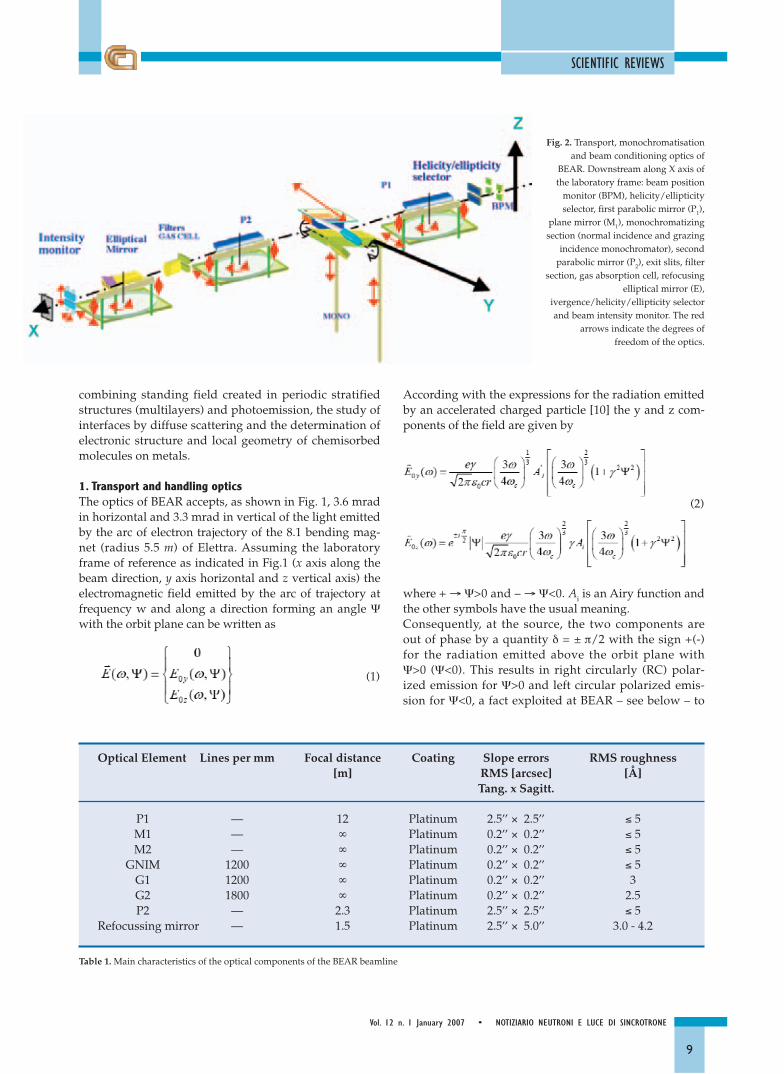
1. Transport and handling opticsThe optics of BEAR accepts, as shown in Fig. 1, 3.6 mradin horizontal and 3.3 mrad in vertical of the light emittedby the arc of electron trajectory of the 8.1 bending mag-net (radius 5.5 m) of Elettra. Assuming the laboratoryframe of reference as indicated in Fig.1 (x axis along thebeam direction, y axis horizontal and z vertical axis) theelectromagnetic field emitted by the arc of trajectory atfrequency w and along a direction forming an angle Ψwith the orbit plane can be written as
(1)
According with the expressions for the radiation emittedby an accelerated charged particle [10] the y and z com-ponents of the field are given by
(2)
where + → Ψ>0 and – → Ψ<0. Ai is an Airy function andthe other symbols have the usual meaning.Consequently, at the source, the two components areout of phase by a quantity δ = ± π/2 with the sign +(-)for the radiation emitted above the orbit plane withΨ>0 (Ψ<0). This results in right circularly (RC) polar-ized emission for Ψ>0 and left circular polarized emis-sion for Ψ<0, a fact exploited at BEAR – see below – to
Optical Element Lines per mm Focal distance Coating Slope errors RMS roughness [m] RMS [arcsec] [Å]
Tang. x Sagitt.
P1 — 12 Platinum 2.5’’ × 2.5’’ ≤ 5M1 — ∞ Platinum 0.2’’ × 0.2’’ ≤ 5M2 — ∞ Platinum 0.2’’ × 0.2’’ ≤ 5
GNIM 1200 ∞ Platinum 0.2’’ × 0.2’’ ≤ 5G1 1200 ∞ Platinum 0.2’’ × 0.2’’ 3G2 1800 ∞ Platinum 0.2’’ × 0.2’’ 2.5P2 — 2.3 Platinum 2.5’’ × 2.5’’ ≤ 5
Refocussing mirror — 1.5 Platinum 2.5’’ × 5.0’’ 3.0 - 4.2
Table 1. Main characteristics of the optical components of the BEAR beamline
Fig. 2. Transport, monochromatisationand beam conditioning optics of
BEAR. Downstream along X axis ofthe laboratory frame: beam position
monitor (BPM), helicity/ellipticityselector, first parabolic mirror (P1),
plane mirror (M1), monochromatizingsection (normal incidence and grazing
incidence monochromator), secondparabolic mirror (P2), exit slits, filter
section, gas absorption cell, refocusingelliptical mirror (E),
ivergence/helicity/ellipticity selectorand beam intensity monitor. The red
arrows indicate the degrees offreedom of the optics.

SCIENTIFIC REVIEWS
10
NOTIZIARIO NEUTRONI E LUCE DI SINCROTRONE • Vol. 12 n. 1 January 2007
produce a beam of positive or negative helicity; indeeda variable ellipticity is obtained – see below – bychanging the angular acceptance in Ψ, which affects theE0y component as shown by the first of eq.’s (2). Thecorresponding dependence of the total intensity isshown in Fig.1 for three photon energies [11].A schematic drawing of the beamline[12] is shown in Fig.2. The optics do not have an entrance slit. The beam po-sition is continuously monitored by a four quadrantdiode device (BPM), the output reading can be used tocorrect the eventual drifts in energy of delivered photons[13]. Downstream from the source the ellipticity/helicityselector follows, its functioning is based on a slit of vari-able aperture (∆Ψ) and of variable vertical position. Thefirst optical element is a parabolic mirror (P1) working at2.5° of grazing incidence defocusing the source into aparallel beam (source in the focal point at 12000 mm).The optics works in sagittal focusing to reduce the ef-fects of slope errors in the dispersing plane (by a factorequal to sin(2.5°) = 4.4x10⁻² in this specific case). The dis-persing/mochromatising section works in parallel light.It features two plane gratings (1200 l/mm and 1800 l/mm)working in the plane-mirror-plane-grating configura-tion (Naletto-Tondello) [14] and a third grating (1200l/mm) working in a normal incidence configuration. Asecond parabolic mirror (P2) working at 2.5° of grazingangle focuses the dispersed light onto the exit slit(placed in the focal point at 2300 mm). The couple ofparabolic mirrors feature a 5.2 demagnification. Themonochromatic beam is eventually refocused at the tar-get position by an elliptical mirror working at 2.5° ofgrazing incidence.The refocusing optics feature 1:1 magnification. Themain characteristics of all the optical elements are listedin Table 1.A chamber containing selectable filters for high orderrejection and a gas cell for energy calibration and reso-lution measurement are placed in sequence between theexit slit and the refocusing mirror.The vertical and horizontal divergence selector (alterna-tively used as ellipticity/helicity selector when workingin the vertical plane) and the beam intensity monitor arelocated between the refocusing optics and the experi-mental chamber. The latter features W and Au meshes of90% and 65% transmission, respectively, working indrain current and LiF beam splitter working at 60° com-bined with a EUV photodiode.The electric field at the target E
→
T, in the laboratory framecan be written as
(3)
where ηT = ETz/ ETy (related to ellipticity, see for instanceref.[15]) and δT is the relative phase shift at the target.Both quantities depend on the setting of theellipticity/helicity selector as described above; small in-fluence on both ellipticity and phase shift can arise fromreflection on the optical elements, mainly in the region ofthe edges of major contaminants (e.g. C and O).Moreover the ellipticity results from an average of the zcomponent of the field on Ψ, depending on the settings
(slit opening and vertical position) of polarization selec-tor; the light dependence on Ψ of the incidence angle onthe optical elements, can introduce a weak Ψ depen-dence of δT which is averaged on the slit aperture.The photon flux at the target position is shown in Fig.3in the 3 eV – 1600 eV photon energy range with a spotwhose cross section is vertical slit (typically 30 µm) × 400µm (variable) and whose maximum divergence is 20 mρvertical × horizontal. The energy bandwidth as a function of photon energy isshown in Fig.4 at different vertical exit slit apertures forthe 1200 l/mm grating (slightly smaller bandwidths areobtained with the 1800 l/mm grating).Single element multilayer polarimetry [16] is used to de-termine and monitor the linear, PL, and circular, PC , po-larization ratios of the beam through the measurementof Stokes parameters (S0, S1, S2 and S3) [17] accordingto the relations
; (4)
Typical values range in the 30 – 100 eV photon energyranges from 0.5 to 0.8 (0.8 to 0.5) for PL (C). A PC ≈ 0.7
Fig. 3. Photon flux at the sample position with: stored current 200 mA,beam energy 2.4 GeV, vertical slit aperture (dispersive plane) 50 µm,normal incidence grating (3-40 eV) and grazing incidence grating (40 –1600 eV).

SCIENTIFIC REVIEWS
11
Vol. 12 n. 1 January 2007 • NOTIZIARIO NEUTRONI E LUCE DI SINCROTRONE
was obtained from circular magnetic dichroism at the CoL23 edge (780 eV).
2. End stationThe experimental chamber [18] is shown in fig.5 andfig.6. The chamber is an UHV chamber (base pressure 1x 10⁻¹⁰ mbar). The apparatus features a high flexibility(together with high precision, repeatability and resolu-tion in positioning of sample and detectors) in the choiceof the scattering geometries both from the point of viewof incidence and detection geometries.The frames of reference of laboratory, ΩL, chamber, ΩC,
manipulator, ΩM are indicated in fig.5 (b) (the sampleframe of reference, ΩS – not indicated - coincides with ΩM
when the sample is aligned). The sample manipulatorfeatures six degrees of freedom resulting from the XYZtranslation stage, and the combination of the rotationΘM, the azimuthal rotation ΦM and the sample normalprecession correction.Once the sample is aligned (precession corrected and ΘM
axis intersecting the surface in the centre of rotation ofthe chamber) the ΘM rotation actuates the rotation matrix
(5)
while the ΨC rotation actuates the rotation matrix
(6)
The combination of the ΘM and ΨC settings permits thepositioning of the sample normal in any position in thelaboratory frame of reference; ΨC scans at fixed ΘM resultin sample normal to precess in the laboratory frame. Combining the two rotations the electric field E
→
T of eq.(3) appears in the sample frame of reference in the form
(7)
This expression shows that by a suitable choice of thecouple of angles ΘM and ΨC a given component of theimpinging electric field can be positioned in any direc-tion with respect to the sample normal.Signal detection includes, basically, light detection by
EUV-XUV photodiodes (typically IRD SXUV-100 siliconphotodiodes), emitted electrons by electron energy ana-lyzer [19] (hemispherical, mean radius 66 mm, angularacceptance ± 2°, energy resolution ~ 1% pass energy inthe range 1-50 eV, equipped with 16 anodes for parallelacquisition) and sample drain current (femto-ammeter,Keithley). Helmholtz coils for magnetic field compensa-tion are provided.
The electron analyzer and four diodes are installed, asshown in Fig.s 5 (a) and (b), on the joint arm of the ex-perimental chamber featuring two mutually orthogonaland independent rotations actuated by an in-air go-niometer, ΘA, and by an in-vacuo ball bearing, ΦA. Thetwo rotations are represented by
(8)
Their combination allows to positioning a detector inany position in the frame of reference of the sample in-dependently from the values of ΘM and ΨC.In Table 2 the angular accuracy range of different rota-tions are reported. The diameter of the confusion sphereof the axes at the chamber center does not exceed 50 µm . Angular detector scans make possible, among others, an-gle resolved photoemission and θ-2 θ reflectivity scans.Optical absorption experiments can be performed both
Fig. 4. Energy bandwidth (experimental – dots; calculated full lines) as afunction of photon energy of BEAR in the 40 – 1400 eV energy range atdifferent vertical aperture of the exit slit.

SCIENTIFIC REVIEWS
12
NOTIZIARIO NEUTRONI E LUCE DI SINCROTRONE • Vol. 12 n. 1 January 2007
in transmission or by measuring sample drain current orAuger or fluorescence yield. Diffuse light scattering ex-periments are feasible as well; possible modes includerocking scans and offset detector scans with typical an-gular resolutions in the scattered wave vector of the or-der of 10-3 nm-1. Additional detectors include diodes infixed position and energy resolved visible luminescence.Test spectra are shown in Fig.7 where the X-ray excitedluminescence from a BaF2 sample; Fig.7 (a) shows an ex-citation spectrum through the Ba M4,5 edges; and Fig.7(b) the spectral response with a fixed incident photonenergy of 130 eV.For the possibilities offered by luminescence see, for
example, [29] and [30] and referenes therein.Sample temperature in the measurement position canrange from ≈100 K to ≈ 500 K.The preparation chamber is shown in Fig.6. The samplemanipulator is shown and the ports where differentitems are installed are indicated. They include a cylin-drical mirror analyzer (CMA), evaporation section(evaporation flange and thickness monitor), ion gun(IG), low energy electron diffraction (LEED), load lockand transfer arm.The experimental chamber is shown rotated by an angleΨC = 45° around the beam axis. Sample temperature inpreparation chamber can range between 100 K and 1500 K.
Table 2. Linear and angular movements.
Frame or Axis Range Resolution
Analyser arm goniometer, primary rotation ΘA 360° 0.001°Analyser arm goniometer, secondary rotation ΦA 220° (± 110°) 0.01°Chamber rotation ΨC 100° 0.1°Manipulator arm goniometer ΘM 360° 0.001°Manipulator xM translation ± 5 mm 1 µmManipulator yM translation ± 5 mm 1 µmManipulator zM translation 20 mm 10 µmManipulator azimuth rotation ΦM 200° 0.1°Manipulator precession correction ΨP 3° 0.01°
Fig. 5. Experimental chamber: (a) CAD image: manipulator shaft, ΘM axis, alignment XYZ stage and goniometer with differentially pumped joints; ΘA
goniometer with differentially pumped joints and in-vacuo ΦA rotation; detector arm with electron analyzer and photo diodes; ΨC axis for chamber rota-tion around beam axis and differentially pumped joints and goniometers. (b) Conceptual of the experimental station, (mainly from the point of view ofrotations and translations of sample and detectors). Different frames of reference, associated to the different moving parts, are indicated. The shaft sup-porting the hemispherical electron analyser is also supporting photodiodes for reflectivity measurements. Light beam is directed along the xL axis.

SCIENTIFIC REVIEWS
13
Vol. 12 n. 1 January 2007 • NOTIZIARIO NEUTRONI E LUCE DI SINCROTRONE
3. Experiments
3.1 Optical constantsThe wide optical range, the continuous spectrum due tothe bending magnet source and the end station in UHVwith surface science facilities make BEAR a powerful ap-paratus for the determination of optical constants of ma-terials. Results related with the determination of the op-tical constants of Ce and Sc films are shown in Fig.8.Both materials are of particular interest in the design andconstruction of multilayer mirrors. Ce and Sc films wereprepared by evaporation on a substrate consisting of C
films of ~ 10 nm thickness deposited onto an electro-formed hexagonal micro-grid of Nickel. The experimental transmittances of Ce films of differentthicknesses evaporated in UHV onto an electron micro-scope nickel grid in the 5 eV – 1000 eV are reported inFig.8 (a) [20]. Experimental values of the real and imaginary part ofthe index of refraction of Sc films are shown in Fig.8 (b)and (c) [21] corresponding to the region of Sc M23 and ScL23, respectively. The extinction coefficient k(ω) was ob-tained by the Lambert law from transmission data at dif-ferent thicknesses; δ(ω) was obtained from k(ω) through
Fig. 6. BEAR preparation chamber: sample manipulator, cylindrical mirror analyzer (CMA), evaporation section (evaporation flange and thickness mon-itor), ion gun (IG), low energy electron diffraction (LEED), load lock, transfer arm. Experimental chamber is shown when rotated of an angle of 45°around the beam axis.

SCIENTIFIC REVIEWS
14
NOTIZIARIO NEUTRONI E LUCE DI SINCROTRONE • Vol. 12 n. 1 January 2007
Fig. 7. X-ray excited luminescence from a test BaF2 sample: (a) excitationspectrum around the Ba M4,5 edges; (b) Spectral response at incidentphoton energy of 130 eV.
a Kramers-Kronig transformation. The δ(ω) and k(ω) val-ues obtained from data base of atomic scattering factors[22] are shown for comparison.
3.2 Multilayers and buried interfacesMultilayers are periodic stacks of layered materials wide-ly used as band pass filters in optical technology [23].The mirror reflectivity (Fig. 9 (a) and (b)) shows apeaked dependence through a mechanism totally analo-gous to the Bragg diffraction from a crystal.At Bragg peak a significant standing field is establishedinside the material with the periodicity of multilayerwhose peaks and valleys move through the interfaceswhile scanning in angle or in wavelength through theBragg condition. This fact results in a modulation of thelocalization of maxima and minima of the excitingfield, in particular at the interfaces inside the multilay-er an aspect which can be exploited in interface spec-troscopy [24].In Fig.9 the result of a photoemission study of the Ru-Siinterface, at fixed photon energy while scanning throughthe Bragg peak of a [Si41.2Å/Mo39.6Å]x40 multilayercapped with 15 Å of Ru, is summarized [25]. A typicalphotoemission spectrum in the region of Ru 3d excita-tion is shown together with the deconvolution into theinterface and bulk Ru components with the addition of asmall feature due to the emission from C 1s. The behav-ior in angle of the two Ru components is shown.
3.3 Interface diffuse scatteringBeside specular reflection, there is a contribution of dif-fuse scattering related to the roughness and the mor-phology of the interfaces [9].These processes are of particular relevance in the per-formance of optical devices including mirrors and mul-tilayers.The process is an elastic process whose kinematics is giv-en by K
→
S = K→
i + q→ z + q→ // where K→
i is the wave-vector ofthe incidence field, K
→
S the wave-vector of the diffusedone and q→ z and q→ // are the normal and parallel compo-nent of the exchanged vector respectively. In this kind ofprocesses the interface roughness is commonly de-scribed by an autocorrelation function of the formH(x - x’,y - y’) = H(R
→
) = 2σ2[1-e-(R/ξ)]where R
→
≡ (x,y), σ the average roughness and ζ the auto-correlation length. In this framework the elastic scatter-ing crossection is given by
and appears as the Fourier transform in q→ // of a potentialbuilt in term of the autocorrelation function and of itsparameters σ and ζ.

SCIENTIFIC REVIEWS
15
Vol. 12 n. 1 January 2007 • NOTIZIARIO NEUTRONI E LUCE DI SINCROTRONE
Fig. 8. Optical constants of materials: (a) transmittance of Ce samples atdifferent thicknesses as a function of photon energy in the 5 eV-1000 eVrange [20]; refraction index n~ (ω) = 1-δ(ω)+ik(ω) of Sc, experimental δ(ω)and k(ω) in: (b) 20-60 eV range and (c) 200-600 eV range [21]. The valuesobtained from the data base of atomic scattering factors [22] are shownfor comparison.
Fig. 9. Reflectivity study of [Si41.2Å/Mo39.6Å ]x 40 multilayer capped with 15Å of Ru. Specular reflectivity in normal incidence (10°) (a) as a functionof the photon energy and (b) as a function of the grazing incidence angleat photon energy =838 eV; (c): Standing field analysis of Ru/Si buried ontop of the Si-Mo multilayer with a photon energy of 838 eV. A typicalphotoemission signal from Ru 3d is shown (see also text). The behavior ofthe areas of the Ru 3d components in Ru and in ruthenium silicides as afunction of grazing angle are shown [25].

SCIENTIFIC REVIEWS
16
NOTIZIARIO NEUTRONI E LUCE DI SINCROTRONE • Vol. 12 n. 1 January 2007
The optical performance (peak reflectivity) of Mo-Simultilayers was contrasted with the construction proce-dures including ion assistance during growth and the in-terposition of a B4C buffer layer between Si and Mo lay-ers [26]. Ion assistance produces in both cases an in-crease of peak reflectivity ~ 5%. Diffuse scattering resultsare summarized in Fig.10.The inspection to the figure shows that ion assistance re-sults in a narrower scattering distribution around the
specular peak indicating an improvement of planarity ofthe interfaces.
3.4 Molecular thin filmsIn Fig. 11 the experimental results of a combined opticalabsorption study in the near UV region in the HOMO-LUMO interband transitions range and at the C K edge,for local structural studies, are reported for polystyrenethin films [27]. The films were prepared by spin coatingon fused quartz plates, with thickness from 50 nm(~2Rg) to 180 nm (~9Rg), where Rg is the unperturbedgyration ratio of the polymer. The UV spectra show cleardifferences with thicknesses attributed to different recip-rocal orientation of benzene ring dimers. Pentacene (Pn, brute formula C22H14) is a π-conjugatedacene molecule formed by five π-conjugated C rings.When deposited on solid substrates Pn can form a“standing up” layer or a “lying down” configuration.This latter geometry can hinder the formation of orderedlayers, a fact that can have technological relevance in thefield of organic electronics. Photoemission valence bandmeasurements and XAS spectra at C K-edge were col-lected for Pn thickness ranging from submonolayer tomultilayer [28]. The evolution of the XAS and VB pho-toemission spectra as a function of the Pn coverage areshown in Fig. 12.The dominant features were assigned to π resonances re-lated to the various molecular occupied (3b2g, 2au and3b3g) and unoccupied (labeled LUMO and LUMO+1)states. The XAS spectra were measured as a function ofthe electric field at the surface.For all the coverages the intensity of the π resonancesshow a strong dichroism. The evolution of the XAS for 1ML when the sample normal is made to precess (scan inΨC at fixed incidence angle) is shown in Fig. 12. A quan-titative analysis (see Fig. 13), based on the assumptionthat the optical absorption is proportional to p→.E
→
2 andby using the parameters of the impinging elliptical elec-tromagnetic field, provides the average tilt angle of themolecule with respect to surface of 10°± 5°.
ConclusionsThe BEAR (Bending Magnet for Absorption Emissionand Reflectivity) was presented.The main parts of the apparatus including the transportoptics and the experimental end stations were essentiallydescribed. A number of scientific results were presenteddealing with at present on going activity at BEAR. Theyincluded optical properties of materials, studies ofburied interfaces, diffuse interface scattering of light andthe determination of electronic structure and local geom-etry of polymers films and chemisorbed molecule on ametal surface.
Fig. 10. Diffuse scattering as a function of q// wave vector for[Mo28Å/Si12Å]x40 and [Mo/ B4C /Si/B4C/Mo] x40. Full dots ion assistedgrowth. Results were obtained in an ω−scan around the specular direction(q// = 0) at 30° with a photon energy 94.7 eV (13.1 nm). After ref. [26].

SCIENTIFIC REVIEWS
17
Vol. 12 n. 1 January 2007 • NOTIZIARIO NEUTRONI E LUCE DI SINCROTRONE
Fig. 11. Optical absorption of Polystyrine films: (A) optical absorption in the 4-9 eV photon energy range, upper panel film thickness of 180 nm ( ~9Rg),lower panel 50nm (~2Rg) (B) optical absorption at C K-edge of 2Rg thick polystyrene at grazing incidence 20° at different direction of the incident elec-tric field along a precession scan. From ref. [27].

SCIENTIFIC REVIEWS
18
NOTIZIARIO NEUTRONI E LUCE DI SINCROTRONE • Vol. 12 n. 1 January 2007
Fig.13 X-ray absorption spectrum at the CK edge of 1 monolayer of pentacene on Ag(111): (a) absorption spectra versus sample normal precession, fordetails see inset and text; (b) area of the first feature of resonance as a function of the molecule tilt angle (see also text) [28].
Fig. 12 Pentacene on Ag(111) as a function of coverage (for details see also text): (a) X-ray absorption at the CK edge; (b) valence band photoemissionwith a photon energy of 60 eV [28]

SCIENTIFIC REVIEWS
19
Vol. 12 n. 1 January 2007 • NOTIZIARIO NEUTRONI E LUCE DI SINCROTRONE
AcknowledgmentsProject funded by INFM and operated by TASC INFM-CNR (http://www.tasc.infm.it/research/bear/ ) At theapparatus is operative as public facility at Elettra(http://www.elettra.trieste.it/UserOffice). Public accessstarted in January 2003,S. D’Addato, S. Valeri, M. Sacchi for their contribution inthe early conception of the project. P. Finetti, G. Selvaggi,G. Gazzadi for their help in different stages of construc-tion and commissioning of the apparatus.The collaboration with Sincrotrone Trieste spa is ac-knowledged.The technical and administrative services of TASC areacknowledged recalling the invaluable assistance of me-chanical service (P. Bertoch, A. Gruden, P.F. Salvador). G. Paolicelli and G. Stefani are acknowledged for theirassistance in design, construction and commissioning ofthe electron analyzer.
References1. http://www.tasc.infm.it/research/bear/;2. http:// www.elettra.trieste.it;3. See for example “Photoemission in Solids” Vol II Eds. L. Ley and M.
Cardona Springer Verlag Berlin (1979).4. N.V.Smith, F. J. Himpsel “Photoelectron Spectroscopy” in “Handbook
on Synchrotron Radiation” Vol. 1b eds. E.-E. Koch, North Holland,NewYork (1983);
5. M. Sunjic and D. Sokcevic, Solid State Commun. 15(1974)165;6. J. Stöhr Journal of Electron Spectroscopy and Related Phenomena 75 (1995)
253;W. L. O’Brien and B. P. Tonner, Phys. Rev. B 50, 12672-12681(1994); M. Altarelli Phys. Rev. B 47, 597-598 (1993) C. W. M. Castletonand M. Altarelli, Phys. Rev. B 62, 1033-1038 (2000)
7. B.L. Henke and J. W. DuMond, J.Appl.Physics 26 (1955) 903;8. For absorption see J. Stoehr “NEXAFS spectroscopy” Springer Verlag
Berlin (1992); for Photoelectron diffraction see D.P. Woodruff et al.,Rep. Prog. Phys. 57 1029-1080(1994); C.S. Fadley, The Study of Sur-face Structures by Photoelectron Diffraction and Auger Electron Dif-fraction Synchrotron Radiation Research: Advances in Surface andInterface Science, Vol. 1: Techniques, editor R. Z. Bachrach (Plenum,New York, 1992)
9. S. K. Sinha, E. B. Sirota, S. Garoff, H. B. Stanley, Phys. Rev. B, 2297-2312 (1988); D. G. Stearns, J. Appl. Phys. 65 (1989) 491;
10. J. Schwinger , Phys Rev 175 (1949) 1912; see for example A. Hofmann“Synchrotron Radiation” ed. By G. R. Greaves and I. H. Munro, Pro-ceedings of the thirtieth Scottish University Summer School inPhysics Aberdeen 1985;
11. The site http://www-cxro.lbl.gov/optical_constants/bend2.htmlprovides numerical values of distribution curves;
12. S. Nannarone et al. AIP Conference Proceedings 705 (2004) 450;13. A. Giglia et al. Rev. Sci Instr. 76 (2005) 063111;14. G. Naletto, G. Tondello Pure Applied Optics 1, (1992) 357;15. R. D. Guenther “Modern Optics” J. Wiley and Sons 1990, p. 38;16. W. B. Westerveld, K. Becker, P. W. Zetner, J. J. Corr, J. W. McConkey,
Appl Optics 24 (1985) 2256; M.-G. Pelizzo, F. Frassetto, P. Nicolosi, A.Giglia, N. Mahne, S. Nannarone, Applied Optics 45, (2006) 1985;
17. Stokes parameters are given by
18. L. Pasquali, A. De Luisa, S. Nannarone AIP Conference Proceedings705 (2004) 1142;
19. G.Paolicelli et al. to be published;20. M. Fernández-Perea, J. A. Aznárez, J. I. Larruquert, J.A. Méndez, L.
Poletto, D. Garoli, A. M. Malvezzi, A. Giglia and S. Nannarone, Proc.SPIE Vol. 6317, 63170V (2006)
21. M.Fernandez-Perea, J.Larruquert, J.A.Arnarez, J.A.Mendez, L.Poletto,A.M.Malvezzi, A.Giglia, S.Nannarone, J.Opt.Soc.Am. A 23(2006)2880;
22. B.L.Henke et al. available at http://www.cxro.lbl.gov/optical_con-stants/
23. E. Spiller, Soft X-Ray Optics, Ed. SPIE, Bellingham, WA (1994);24. S.-H. Yang, B. S. Mun, N. Mannella, S.-K. Kim, J. B. Kortright, J. Un-
derwood, F. Salmassi, E. Arenholz, A. Young, Z. Hussain, M. A VanHove and C. S Fadley, J. Phys.: Condens. Matter 14 (2002);
25. Mahne et al to be published.26. A. Patelli, V. Rigato, G. Salmaso, F. Borgatto, S. Nannarone, LNL An-
nual Report 2004;27. S.Chattopadhyay, A.Datta, A.Das, A.Giglia, N.Mahne, S.Nannarone,
to be published;28. M. Pedio et al., submitted to Applied Surface Science;29. T.K. Sham et al., Phys. Rev. B 70, 0405313 (2004);30. I. Salish et al., Phys. Rev. B 69, 245401 (2004).
[Note of the Authors] - The scientific community of the Italian Surface Physics lost during the year 2006 MassimoSancrotti a friend of many of us, an excellent physicist and an enthusiastic teacher and organiser. This paper is devotedto his memory.

20
NOTIZIARIO NEUTRONI E LUCE DI SINCROTRONE • Vol. 12 n. 1 January 2007
The ESRF Long-Term Strategy up-grade is an ambitious renewal pro-gramme that aims to ensure theleading scientific position of the fa-cility over the next two decades.«The upgrade is a very real chal-lenge for us, but is essential if theESRF is to continue to provide theEuropean scientific community withthe very best experimental tools»,says Professor Bill Stirling, DirectorGeneral of the ESRF. New and refur-bished beamlines are proposed toanswer new scientific needs, under-pinned by a programme to maintainand refurbish the accelerator com-plex which is at the heart of the ES-RF’s activities. The project includeshighly specialised nano-focus beam-lines, with even brighter hard X-raybeams, and the renewal of beamlinecomponents such as detectors, op-tics, sample environment and sam-ple positioning.The upgrade will involve the recon-struction of about one third of thebeamlines for significantly improvedperformance. Some will be extendedto about 120 meters to providenanometer focus capabilities.
In addition, the accelerator complexwill be upgraded, and science-dri-ven partnerships with both industryand academia will be developed, allunderpinned by an ambitious instru-ment development programme.This project is the result of threeyears of consultation and work be-tween the ESRF and the scientificuser community. This renewal pro-gramme will be submitted to theCouncil in 2007 and, if approved,would start in 2008.The down time for the facility wouldbe as short as possible in order tominimise disruption of the users’scientific programmes. The ESRF´s
upgrade is present in the first Euro-pean Roadmap for Research infra-structures.The document presents 35 largescale research infrastructure projects,identified as being of key impor-tance for the development of Euro-pean science and innovation.The ESFRI roadmap will allow acommon European approach to thedevelopment of such facilities, sup-port the definition of priorities andaid the pooling of the significant fi-nancial resources required for theirrealisation.
M. Capellas EspunyESRF Press Officer
MUON & NEUTRON &SYNCHROTRON RADIATION NEWS
News from ESRFThe ESRF’s Upgrade Programme
Figure 1. Artist’s impression of a section of the future extended and upgraded ESRF ExperimentalHall. This upgrade will enable longer beamlines to take advantage of the ESRF’s fine X-ray sourceproperties and allow specialised centres to be built around beamline clusters sharing scientificand/or technological expertise. Credits: ASSA.
News from ILLA direct Test of E = mc2
One of the most striking predictions ofEinstein’s theory of special relativity isprobably the best known formula in sci-ence: E = mc2. This report describesthe most precise direct test of thismass/energy relationship to date.Com-bining ultra-precise atomic mass andgamma-ray wavelength measurementsinvolving isotopes of silicon and sul-phur, we obtain two tests that separate-
ly confirm Einstein’s relationship andyield a combined result of 1–∆mc2/ E= (–1.4 ± 4.4) × 10–7.
A straightforward verification ofEinstein’s mass/energy equivalenceprinciple E = mc2 would be possibleby measuring the energy of annihila-tion radiation of two particles. How-ever, measurement of the 511 keV
annihilation radiation of the electronand positron is complicated by ini-tial kinetic energy, while accuratemeasurement of annihilation radia-tion of heavier particles is even moredifficult. An elegant way out is toconsider the mass and energy bal-ance in a nuclear reaction, which isinitiated by particles with a mini-mum of kinetic energy. Such a reac-

21
Vol. 12 n. 1 January 2007 • NOTIZIARIO NEUTRONI E LUCE DI SINCROTRONE
tion is realised when a nucleus withmass number A captures a neutron.In this case the mass of the resultingisotope, with mass number A+1,ought to differ from that of the origi-nal nucleus (plus unbound neutron)by the neutron binding energyEn(A+1). In most reactions all of theEnergy is emitted as gamma rays,the wavelength λι of which can beprecisely measured via Bragg dif-fraction. In this case Einstein’s equa-tion can be rewritten as
(MR(A)+MR(n)–MR(A+1))c2 == 1/u En(A+1) = 103NA hc Σ 1
ëι,
(1)
where the Avogadro constant NA re-lates a relative atomic mass MR (inunified atomic mass units u) to itsmass in kilograms m, h is the Planckconstant and c the speed of light. The summation in the right part ofequation (1) runs over all gammarays of a cascade connecting captureand ground state. The mass of theneutron can be eliminated fromequation (1) by introducing themasses of Hydrogen 1H and Deuteri-um 2D combined with the wave-length λD corresponding to the deu-terium binding energy.
(MR(A)+MR(2D)–MR(1H)–MR(A+1)) == 103 NAh/c (Σ 1
ëι– 1ëD
)(2)
The molar Planck constant isNAh = 3.990 312 716(27)·10-10 J s(u/Kg), and has been independentlyconfirmed at the 5·10-8 level by di-verse experiments through its rela-tionship with the fine structure con-stant [1].The gamma-ray wavelengths havebeen measured in a collaboration ofscientists from the ILL and the Na-tional Institute of Standards andTechnology using the GAMS4 crys-tal spectrometer, which is positionedat the H6/H7 tangential beam tube[2] of the ILL. Gamma rays from aninpile target are diffracted by twonearly perfect flat Si crystals whoselattice spacing d has been carefully
determined. The diffraction anglesare measured with angle interferom-eters. These interferometers can becalibrated with respect to an ab-solute angle of 2π using a precisionoptical polygon. As the calibrationangle is much larger than the mea-sured Bragg angles, a very goodnon-linearity of the angle interfer-ometer is required. The energies ofgamma rays to be measured rangedfrom 0.8 to 5.5 MeV. Because the dif-fraction angle of a 5 MeV gamma rayby a low order reflection is less than0.1 degrees, our binding energy de-terminations were limited by ourability to measure the diffraction an-gles of the high-energy gamma raysbetter than 10-8 degrees. From the ex-periments we report values of
En(29Si)=hc/(0.146 318 275 (86)·10-12 m),
En(33S)=hc/(0.143 472 991 (54)·10-12 m)
and En(2D)=hc/(0.557 341 007 (98)·10-12 m) [3].These numbers combine to yield rel-ative uncertainties of 5.1 10-7 (33S)and 8.0 · 10-7 (29Si) for the right-handside of equation (2). The mass differ-ence was determined at the Massa-chusetts Institute of Technology us-ing a new technique to directly com-pare the cyclotron frequencies of twodifferent ions simultaneously con-fined in a Penning trap [4]. Thisgreatly reduces many systematic andstatistical errors, particularly thosedue to magnetic field fluctuations.Two independent experiments with28,29Si and 32,33S were carried out. Dur-ing the measurements, the two ions
MUON & NEUTRON &SYNCHROTRON RADIATION NEWS
Figure 1. Illustration of the experimental concept to compare the mass and energy balance in a ther-mal neutron capture reaction. The atomic masses are measured using precision Penning Trap mea-surements at MIT (USA), while the energy is extracted by means of a diffraction measurement atthe GAMS spectrometers of the ILL.

MUON & NEUTRON &SYNCHROTRON RADIATION NEWS
22
NOTIZIARIO NEUTRONI E LUCE DI SINCROTRONE • Vol. 12 n. 1 January 2007
A variable-temperature single-crystalLaue diffraction study on VIVALDI haslocated the gas absorption sites within ahydrogen-loaded metal-organic frame-work. Neutron Laue diffraction offersunique advantages in the characterisa-tion of such materials, which are possi-ble candidates for fuel storage in the au-tomotive industry.
In the first experiment of its kind, avariable-temperature (5-300K) sin-gle-crystal Laue diffraction studyon VIVALDI has been used to lo-cate the gas absorption sites withina hydrogen-loaded metal-organicframework. Low-temperature neutron Laue dif-fraction offers unique advantages in
the characterisation of these materi-als, providing information essentialto the development of this novelclass of framework compounds.One use of these compounds as gasstorage media, in conjunction withfuel cells, would be in the automo-tive industry.The technology already exists in the
are placed on a common circular or-bit (magnetron mode), on oppositesides of the centre of the trap andseparated by a distance of about 1mm. Correcting for the polarisationinduced shifts of the cyclotron fre-quencies we obtain ion mass ratios.Correcting further for the masses ofthe missing electron and the chemi-cal binding energies of the atom weobtain neutral mass ratios ofMR(32S)+MR(H)–MR(33S) == 0.00843729682(30) uand MR(28Si)+MR(1H)–MR(29Si) == 0.00825690198(24) u.By adding MR(2D)-2MR(1H) = – 0.001548 286 29 (40) u to each one, we ob-tain the mass differences of equation(2) with a relative uncertainty ofabout 7 · 10-8 for both.
The comparison of the measured en-ergies and masses leads to two inde-pendent tests of (1- E /mc2) of2.1(5.2)·10-7 and -9.7(8.0)·10-7 withsulphur and silicon isotopes respec-tively, and a combined value of-1.4(4.4)·10-7.This test is 55 times more accuratethan the previous best direct test of E= mc2, performed by comparing theelectron and positron masses to theannihilation energy. The error onthis comparison is currently domi-nated by the uncertainty on the gam-ma-ray measurements.The major problems within thesemeasurements are the insufficientnon-linearity and time stability ofthe angle interferometers.However, there are already projects
to improve these parameters further,which would eventually allow theresults to be improved by one orderof magnitude.
References1. P.J. Mohr and B.N. Taylor, Rev. Mod. Phys. 77,
(2005) 1-1072. E.G. Kessler et al., Nucl. Instr. Meth. A 457,
(2001) 187-2023. M.S. Dewey et al., http://arxiv.org/abs/nu-
cl-ex/0507011, submitted to Phys. Rev. C.4. S. Rainville, J.K. Thompson, and D.E.
Pritchard, Science 303, (2004) 334-338
S. Rainville*Harvard University and
MIT Cambridge, USA
J.K. Thompson*, D.E. PritchardMIT Cambridge, USA
E.G. MyersFlorida State University, Tallahassee
J.M. BrownOxford University
M.S. Dewey, E.G. Kessler Jr., R.D. Deslattes
NIST Gaithersburg
H.G. Börner, M. Jentschel, P. MuttiILL
* These authors contributed equally to thiswork.
Figure 2. View of the GAMS4 double flat crys-tal spectrometer. The orientation of two perfectSi crystals is controlled by optical angle inter-ferometers. The absolute calibration of the in-terferometers is carried out using an opticalpolygon.
Hydrogen Storage in a Metal-Organic Framework

23
Vol. 12 n. 1 January 2007 • NOTIZIARIO NEUTRONI E LUCE DI SINCROTRONE
form of fuel cells to convert storedchemical energy, in the form of hy-drogen gas, directly into electricalenergy with high efficiency [1].However, the crucial factor that ishindering progress towards the com-mercial exploitation of these devicesis the safe and efficient storage of thehydrogen fuel gas. The design and technological devel-opment of storage media to over-come this difficulty is at the forefrontof current research [2].Of the various materials under in-vestigation, ordered porous materi-als such as metal-organic frame-works, are favourably considered tobe capable of fulfilling this role [3].The ability to adapt the surfacechemistry of the framework cavitiesmakes metal-organic frameworksparticularly attractive contenders forhydrogen-storage applications.By optimising the chemical and elec-tronic nature of the framework ar-chitecture, the gas uptake, at a givenpressure and temperature, can bemaximised.In a systematic approach to the mod-ification of a particular framework,with the aim to improve its gas ab-sorption properties, it is imperativeto understand which sections of thestructure interact strongly with the
physisorbed hydrogen gas.Once they are identified, these ele-ments of the structure can be en-hanced to increase the absorptioncharacteristics of the frameworkmaterial.Although there have been examplesreported of the use of single crystaland powder x-ray diffraction for de-termining the location of absorptionsites for a variety of gases (CO2, Ar,and O2) within porous coordinationpolymer complexes [4], this informa-tion is of limited use in terms of theadvancement of these materials forhydrogen storage.It is of greater benefit to determinethe location of hydrogen gas mole-cules themselves included within aframework structure, as this knowl-edge is of direct relevance.However, here x-ray diffraction isless suitable than neutron diffrac-tion, since the accuracy of the resultsobtained is greatly limited by thelow x-ray scattering ability of hydro-gen, particularly when the hydrogenundergoes large thermal vibration.In a pioneering experiment of itskind, a variable temperature (5-300K) single-crystal Laue neutron-diffraction study was conducted onVIVALDI, to locate the gas absorp-tion sites in a 0.1 mm3 hydrogen-
loaded crystal of Zn4O(CO2)6
[Zn4O(1,4-benzenedicarboxylate)](figure 1). The greater adsorptionvolume associated with a singlecrystal compared to a powder wasan essential reason for this study.Two sites were unambiguously iden-tified, and these both display thecharacteristics of physiabsorbed hy-drogen molecules [5]. The space-fill-ing diagram of one of the frameworkcavities at 5K (figure 2) shows thatthe hydrogen gas congregates in thevicinity of the framework nodes.The gas enters and leaves the frame-work reversibly on cooling and heat-ing, even in a sealed capillary, witheight H2 molecules absorbed perframework formula unit at 5K, fourH2 molecules at 50K, and none at 120K. At 120K, the evacuated frame-work retains its integrity eventhough it contains ~77% of voidspace that is accessible to the hydro-gen gas.At 5K the physisorbed hydrogen gasoccupies approximately just 12% ofthis volume at a loading pressure of1 atm. Higher pressures may resultin further absorption near the organ-ic linker molecules, as predicted bygrand canonical Monte-Carlo simu-lations [6], and we will pursue thisaspect in future neutron studies.
MUON & NEUTRON &SYNCHROTRON RADIATION NEWS
Figure 2. A) The location of the two hydrogen absorption sites at 5K relative to the Zn4O(CO2)6framework. The H1-H2 site is 100% occupied at 50K, 30K and 5K; H4 is 98% occupied only at 5K.B) Space-filling diagram of one of the framework cavities at 5K. Purple: zinc; red: oxygen; black:carbon; grey: framework hydrogen atoms; gold: absorbed hydrogen gas.
Figure 1. One unit cell of the Zn4O(CO2)6 struc-ture. After accounting for the van der Waalsradii of the framework atoms, a sphere with adiameter of ~8 Å could diffuse freely throughthe framework.

MUON & NEUTRON &SYNCHROTRON RADIATION NEWS
24
NOTIZIARIO NEUTRONI E LUCE DI SINCROTRONE • Vol. 12 n. 1 January 2007
The success of the experimentdemonstrated the ability of Laueneutron diffraction to study verysmall single crystals by neutronstandards, often in compromised en-vironments such as gas-exchangecapillaries.This means that this technique can beexpected to play a key role in thestructural study of framework mate-rials in the immediate future.
References1. B.C.H. Steele and A. Heinzel, Nature 414
(2001) 3452. L. Schlapbach and A. Züttel, Nature 414
(2001) 3533. M.J. Rosseinsky, Micropor. Mesopor. Mater.,
73 (2004) 154. Y. Kubota, M. Takata, R. Matsuda, R. Kitaura, S.
Kitagawa, K. Kato, M. Sakata and T.C.Kobayashi, Angew. Chem. Int. Ed., 2005, 44, 920
5. E.C. Spencer, J.A.K. Howard, G.J. McIntyre,J.L.C. Rowsell and O.M. Yaghi, Chem.Comm. 2005, accepted
6. T. Sagara, J. Klassen and E. Ganz, J. Chem.Phys. 121 (2004) 12543
Elinor C. SpencerDurham University and ILL
Judith A.K. HowardDurham University
Garry J. McIntyreILL
Jesse L.C. Rowsell andOmar M. Yaghi
University of Michigan, Ann Arbor
On October 23, 2006, the groundbreaking ceremony was held forLinac Coherent Light Source(LCLS), the world’s first X-ray free-electron laser.Scheduled for completion in 2009 atthe U. S. Department of Energy’sStanford Linear Accelerator Center,the LCLS will produce ultra-fast, ul-tra-short pulses of X-rays a billiontimes brighter than any other sourceon earth. The LCLS represents the4th generation of machines designed
to produce synchrotron radiation forscientific studies, an idea originallypioneered at SLAC in the 1970s. Un-like a circular storage ring, the LCLSwill produce x-rays using the final1/3 of SLAC’s existing linear accel-erator, in conjunction with long ar-rays of undulator magnets.Nearly 1,000 attendees listened tothe keynote address of DOE UnderSecretary of Science Raymond L.Orbach.The LCLS project is a collaboration
among Department of Energy labo-ratories including Argonne NationalLaboratory, Brookhaven NationalLaboratory, Los Alamos NationalLaboratory, Lawrence LivermoreNational Laboratory, and the Uni-versity of California Los Angeles.
Allen E. EkkebusSpallation Neutron Source, Oak Ridge
National Laboratory
News from LCLSGround Breaking for Linac Coherent Light Source
A map of LCIS site

MUON & NEUTRON &SYNCHROTRON RADIATION NEWS
25
Vol. 12 n. 1 January 2007 • NOTIZIARIO NEUTRONI E LUCE DI SINCROTRONE
News from NMI3Development of Neutron Detectorsfor Very High Resolutions and Counting Rates
In the JRA DETNI (DETectors forNeutron Instrumentation) three nov-el modular thermal neutron area de-tector types, based on thin solid neu-tron converter layers, are being de-veloped for time- and wavelength-resolved neutron detection in single-neutron counting mode, with two-dimensional spatial resolutions ofup to 50-100 µm FWHM, sub-mi-crosecond time-of-flight resolutionand counting rates of up to 108 neu-trons/s per detector module, i.e. forcoping with the highest resolutionand rate requirements at next gener-ation pulsed spallation sources likeESS. Recording only signals abovenoise in single-event counting, the
image contrast is greatly improvedin comparison to integrating detec-tors, like CCD cameras or imageplates. In addition, by scanning in asingle measurement a full wave-length train, in time-of-flight radiog-raphy-tomography the contrast ofindividual elements in the sample isenhanced specifically in element-specific resonances of the total neu-tron scattering cross section. In addi-tion to imaging, applications e.g. intime-of-flight Laue diffraction, very-high resolution single crystal diffrac-tion and reflectometry are envis-aged, among others. The detectortypes are:• Four-fold segmented modules of
Silicon micro-strip detectors (Si-MSD), with each segment com-prising a 157Gd converter layer be-tween two double-sided Si sensorsof 51 · 51 mm2 sensitive size andwith 80 µm pitch in the X and Ymicro-strip readout planes.
• Hybrid low-pressure micro-stripgas chamber (MSGC) detectors of254 · 254 mm2 sensitive size withthree-stage gas amplification gapsand novel two-dimensional posi-tion-sensitive multilayer MSGCplates either side of a composite157Gd/CsI converter which is coat-ed with columnar CsI secondaryelectron emitter layers.
• CASCADE detectors with stacks
News from NCXTNational Center for X-ray Tomography
The National Center for X-ray To-mography (NCXT) was dedicated onOctober 23, 2006.
It is located at the Advanced LightSource (ALS) of the U.S. Departmentof Energy’s Lawrence Berkeley Na-tional Laboratory.This new center features a first-of-its-kind x-ray microscope.According to cell biologist and mi-croscopy expert Carolyn Larabell,who is the principal investigator forthe new center, «X-ray microscopy isan emerging new technology thatexpands the imaging toolbox for celland molecular biologists, and weare going to make this technologyavailable to the greater biologicalcommunity».The NCXT is being funded withgrants from the U.S. Department ofEnergy (DOE) and from the National
Institutes of Health (NIH).As an NIH technology resource cen-ter, the NCXT will be available toqualified biomedical researchersthroughout the nation.The centerpiece of the NCXT is thefirst soft x-ray transmission micro-scope to be designed specifically forbiological and biomedical applica-tions. It is capable of imagingwhole, hydrated cells at resolutionsof about 35 nanometers, and specif-ic structural elements within thecell at a resolution of at least 25nanometers.
Allen E. EkkebusSpallation Neutron Source, Oak Ridge
National LaboratoryThe new soft x-ray microscope at the NationalCenter for X-ray Tomography captured its firstx-rays on August 23, 2006

MUON & NEUTRON &SYNCHROTRON RADIATION NEWS
26
NOTIZIARIO NEUTRONI E LUCE DI SINCROTRONE • Vol. 12 n. 1 January 2007
of cascaded GEM (Gas ElectronMultiplier) foils on either side of adouble-sided, two-dimensionalposition-sensitive readout elec-trode. The GEM foils are coated onboth sides with 10B converter lay-ers and drift the secondary elec-trons, released in the gas by thesecondary ions emitted form 10Bafter neutron capture, to a lastGEM foil where they are amplifiedfor two-dimensional detection.
For readout, in DETNI two novelself-triggered high-rate ASIC (Appli-cation Specific Integrated Circuit)chips [1], subsequent ADC-FPGAboards with Gigabit glass fiber read-out links and the required data ac-quisition firmware and software arebeing developed. The ASICs, a low-noise 128-channelchip optimized for the Si-MSD andstrip rates of 160 khits/s, and a32-channel chip optimized for theMSGC with variable amplificationand strip rates of 900 khits/s, deliverspatial, analogue amplitude and fasttime stamp information with 4 and 2
ns resolution, respectively, the latterbeing necessary for X-Y strip correla-tion with low chance coincidencerate. The amplitude readout is usedfor improving the spatial resolutionby center-of-gravity interpolationbetween the strips and for gating forbackground suppression. Prototypes of all three detector typesare being prepared presently togeth-er with the readout electronics fortesting in 2007.
References1. A.S. Brogna et al., N-XYTER, a CMOS read-
out ASIC for high resolution time and am-plitude measurements on high rate multi-channel counting mode neutron detectors,Nucl. Instr. and Meth. A 568 (2006) 301-308
S.S. Alimov1,2, A. Borga3,A. Brogna1,2, S. Buzzetti2,4,
F. Casinini5, W. Dabrowski6,T. Fiutowski6, B. Gebauer1,
G. Kemmerling3, M. Klein2,B. Mindur1,6, C. Petrillo5,
F. Sacchetti5, C.J. Schmidt7,H.K. Soltveit2, R. Szczygiel6,
Ch. Schulz1, C.Thielmann3,U. Trunk8, P. Wiacek6, Th. Wilpert1
1Hahn-Meitner-Institut Berlin, GlienickerStr. 100, D-14109 Berlin, Germany
2Physikalisches Institut der UniversitätHeidelberg, Philosophenweg 12,D-69120 Heidelberg, Germany
3Zentralinstitut für Elektronik, For-schungszentrum Jülich,52425 Jülich, Germany
4INFM & Dipartimento di Elettronica e
Informazione, Politecnico di Milano,Piazza Leonardo da Vinci 32,
Milano I-20133, Italy5INFN & Dipartimento di Fisica, Univer-
sita di Perugia, Via A. Pascoli,Perugia I-06123, Italy
6Faculty of Physics and Applied ComputerScience, AGH University of Science and
Technology, al0. Mickiewicza 30,30-059 Krakow, Poland
7Gesellschaft für Schwerionenforschung,Planckstr. 1, 64291 Darmstadt, Germany
8Max-Planck-Institut für Kernphysik,Saupfercheckweg,69117 Heidelberg,
Germany
Neutron Optics and Phase Space TransformersThe most efficient means for increas-ing the flux at beam lines for neu-trons is the use of advanced focusingtechniques based either on diffrac-tive optics or the reflection of neu-trons from surfaces that are coatedwith artificial multilayer structurestermed “supermirror”. In addition,the flux can be increased by activelychanging the phase space of the ra-diation, for example by cooling thespectrum of the neutrons and/or bymoving monochromators. Of course,the flux can also be increased by in-creasing the source strength as it isfor example done in the US andJapan, where new high-power spal-lation sources are being built andcommissioned. The goal of the JRA3-collaboration
is the development and explorationof new focusing techniques andphase space transformations that al-low for the investigation of smallsamples as they occur often in thefields of soft condensed matter andin materials research as well as ma-terials exposed to extreme condi-tions, for example high magneticfields and/or high pressure.In order to increase the neutron fluxfor small angle neutron scattering(SANS), a multi-beam collimator hasbeen developed, featuring 7 maskswith 51 pinholes each. First test ex-periments using a suspension of La-tex spheres with a diameter of 225nm prove that the principle is work-ing leading to the expected fluxgains while maintaining the resolu-
tion. For inelastic neutron scatteringexperiments, the Q-resolution canoften be significantly relaxed. There-fore, a concept of focusing devicesconcentrating the neutron beams byreflection from supermirror-coatedglass tubes that are ellipticallycurved has been developed. A fluxgain of approximately 25 has beenmeasured using neutrons with awavelength in the range 3 Å < λ <6Å. In order to increase the efficiencyfurther, improved coating tech-niques using magnetron sputteringhave been developed thus increasingthe number of diffracting layersfrom 500 to several thousand. Thesystematic studies have led to an im-provement of the coatings with re-spect to the critical angle (m ≅ 4.2)

MUON & NEUTRON &SYNCHROTRON RADIATION NEWS
27
Vol. 12 n. 1 January 2007 • NOTIZIARIO NEUTRONI E LUCE DI SINCROTRONE
Muons provide a unique probe ofatomic level structure and dynamicsand the experimental technique isknown as Muon Spin Rotation, Re-laxation and Resonance (µSR).A wide variety of properties can beinvestigated across a broad rangeof systems, including magnetic ma-terials, superconductors, semicon-ductors and molecular/polymericsystems.A muon can be thought of as a mi-croscopic magnetometer, with spin-1/2 and a magnetic moment threetimes that of the proton, and can beused to inform on local magneticstructure and dynamics.The muon mass is approximatelyone-ninth that of a proton, and inmany experiments muons are usedas a mimic to determine proton orhydrogen sites and dynamics, for ex-ample in semiconductors, metal hy-drides and proton conductors.Muons provide a complementaryprobe of condensed matter to othertechniques such as neutron scatter-ing and magnetic resonance, and areused by many research groupsacross Europe. This JRA is aimed atadvancing technologies in a numberof areas relevant to the performanceof muon experiments. These advances will benefit thewhole European muon community,and are aimed at enhancing the ca-pabilities of the European muon fa-cilities to extend their potential forcondensed matter investigations.Specifically, this JRA is aimed at de-
velopments in three areas:1. Detectors for muon spectroscopy;
in particular, development of fast-timing detectors and those capableof providing position information.
2. Instrument simulation; in particu-lar, the development of code toenable full simulation of muonspectrometers.
3. Advanced experimental methods,in particular development of novelpulsed techniques.
State-of-the-artDetectorsPosition sensitive detectors: our recentstudies have shown that, in additionto silicon-based detectors, scintillat-ing fibres too are very promising asposition-sensitive detectors for µSR.A detailed work including both sim-ulation and testing, has shown theequivalence of signals generated bymuon-decay-positron with thosearising from common beta emitters:this will make future test proceduressimple. Fast and magnetic field insensitive de-tectors: the performance Avalange-Photo-Diods/SiPMs detectors at lowtemperatures is at present known ina cryogenic environment. Mechani-cal difficulties concerning the assem-bly of the AMPD array on printedcircuit boards, will be overcome byusing light guides for signal trans-mission. Detailed Monte Carlo simu-lations for an improved light outputand an increased efficiency are beingcarried out. The results will be used
in the design of a revised version ofthe detector layout. Beside beingvery fast (some tenths of ns), the re-sponse of the blue-sensitive AMPDs,is expected to be also magnetic fieldindependent, as already shown fortheir green sensitive counterparts,making them an ideal choice for thedetector system of a high-field spec-trometer.
Simulations of detectors andspectrometersEfforts were devoted to the inclusionof positron track simulations into theexisting simulation code, and in par-ticular in the test against real data.The magnetic field-dependent effectswere investigated by using a pur-posely built positron detector, whichincludes two mobile detecting ele-ments mounted inside a supercon-ducting solenoid. The observed ef-fects seem to depend not only on thecyclotron motion of the positrons,but also on the field induced motionof the muons in the incoming beam.
Advanced µSR techniquesThe development of µSR in pulsedenvironments, e.g. microwave andRF-µSR, has been the main focus.The technology associated withcrossed-coil RF excitation has nowdeveloped to the point where tech-niques dependent on this technolo-gy (e.g. g-value determination andRF nuclear decoupling) make a reg-ular contribution to the ISIS userprogramme. RF decoupling, in par-
MUONS – Instrumentation forSpin-Polarized Muon Spectroscopy
and to reflectivity (R ≅ 0.70). It be-came clear that the morphology ofthe substrate is of utmost impor-tance to obtain an excellent perfor-mance. Elliptic guides have been de-veloped for the transport of the neu-
trons from the moderator to thespectrometer. First prototypes showthat the expected flux gains of morethan a factor of five compared to reg-ular neutron guides can be realised.It is gratifying to see that the new
techniques are already being incor-porated at the new Target Station 2 atISIS that is presently in the construc-tion phase.
Peter BöniTUM, for the JRA3 – NO-PST Team

MUON & NEUTRON &SYNCHROTRON RADIATION NEWS
28
NOTIZIARIO NEUTRONI E LUCE DI SINCROTRONE • Vol. 12 n. 1 January 2007
The DLAB JRA within NMI3 is fo-cused on the development of meth-ods for the efficient and cost-effec-tive deuteration of biological macro-molecules. The project is fully dedi-cated to biological neutron scatter-ing , but has an important link to so-lution and solid state NMR. Themethods that are being developedas part of the project are now start-ing to have an impact on biologicalneutron scattering experiments onsolutions, fibres, crystallographyand dynamics.Real results in these areas that havebenefited from these methodologicaldevelopments are now coming intothe scientific press. In very broadterms, DLAB work cover the follow-ing general areas:1. Methods aimed at driving downthe cost of deuterated biomole-cules, thereby enhancing access.This is being done through the de-velopment of new methods to opti-mise bacterial growth. Two ap-proaches are being deployed here(I) the development of bacterialstrains that are more tolerant ofD2O and deuterated carbonsources, (II) fundamental proteomicapproaches in which the molecularnetworks involved in adaptationare investigated. 2. Methods aimed at developing theuse of new organisms for deuteri-um labelling, thereby extending therange of systems that can be deuter-ated. Here techniques are being de-
veloped to label organisms such asRalstonia eutropha and the eucaryoticorganism Pichia pastoris. to providevehicles for the expression of hetrol-ogous proteins that can not be ex-pressed in E. coli.3. Optimisation of methods for theselective deuteration of biologicalmacromolecules so that the visibili-ty of particular regions of thesestructures is enhanced in model-ling. A variety of approaches are be-ing developed, ranging from meth-ods whereby particular residues aredeuterated to those that facilitatemacro-scale labelling of large multi-component systems.4. Methods aimed at optimising se-lective hydrogenation of complexbiological systems to enable hydro-gen incoherent scattering studies ofspecific components. Techniquesfor the hydrogen labelling of specificamino acids in deutrated membraneproteins are being extended to vari-ous prockaryotic and eukaryotic sys-tems of major biological interest. Over and above the specific techni-cal goals, the DLAB project aims toextend its activities and expertise aswidely as possible throughout theEuropean neutron scattering com-munity. Within the current frame-work this is gradually happeningvia the network of neutron scatter-ing partners and NMR observerswithin the DLAB project. It is alsohappening through the dissemina-tion of results from successful
deuteration/labelling projects thathave exploited the expertise devel-oped. Many of these have used neu-tron scattering facilities at the ILL,but experiments on labelled sys-tems have also been carried out atISIS (where reflectometry resultshave complemented ILL SANSmeasurements and ssNMR studies,both also exploiting the labelling)and at Juelich (where measure-ments from the BSS spectrometerhave complemented data from oth-er spectrometers with different en-ergy resolutions).Clearly the involvement of all Euro-pean neutron scattering facilitiesinvolved in biological work is es-sential and this is a primary con-cern for this JRA in the context ofFP7. One intriguing aspect emerg-ing from current activities is thefact that neutron/NMR comple-mentarity is not restricted to mutu-al benefit simply through labellingrequirements. New neutron pro-posals are indeed emerging as a re-sult of the NMR deuteration & la-belling work because NMR usersare discovering first hand the valueadded to their work through theuse of neutrons. There is l ittledoubt that the same could be saidof many other techniques.
Trevor ForsythJRA7 – D-LAB Coordinator
Institute Laue LangevinKeele University, UK
Development of Methods for Biological Deuteration
ticular, requires large RF fields forefficient decoupling, and this tech-nique has greatly benefited fromwork carried out to improve the ef-ficiency of power delivery to thesample. Significant effort has alsobeen devoted to the developmentand demonstration of a microwavespectrometer at ISIS. A signal gen-
erator, power amplifier and othermicrowave components were pur-chased, and these, together with anin-house designed and built cavity,formed the basis of the instrument.With the cavity optimised at a fre-quency ~3GHz test experimentswere carried out, observing clearresonances from the 3-4 transition
of muonium formed by muonsstopped in fused quartz sample. Fi-nally, efforts continued to measurean acoustic muon spin resonancesignal.
Cesare BucciJRA8 – MUONS Coordinator
MUON & NEUTRON &SYNCHROTRON RADIATION NEWS
29
Vol. 12 n. 1 January 2007 • NOTIZIARIO NEUTRONI E LUCE DI SINCROTRONE
As a result of progress in the field ofMultiwire Proportional Chambers(MWPC), Microstrip Gas Counters(MSGC) and associated electronics,the performance of neutron gas de-tectors have constantly improvedover the last three decades.Nevertheless, it is obvious that theexperimental conditions imposed byfuture spallation sources will not befulfilled by present gas detectors.This situation, together with astrong demand to improve existinginstruments, explains why detectordevelopment has been given highpriority within the NMI3 project(Neutrons & Muons Integrated In-frastructure Initiative).The MILAND (MIllimetre resolutionLarge Area Neutron Detector) JointResearch Activity aims to deliver, bythe end of 2007, a fully operationaldetector of 32 cm x 32 cm sensitivearea having a spatial resolution of1 mm FWHM.Considering other parameters likegamma sensitivity, counting rate,uniformity, and robustness, we ex-pect the performances of the MI-LAND detector to exceed those ofexisting neutron detectors. Duringthe first two years of the project, sev-eral techniques have been studiedand one of them has been selected:1. the principle of a GSPC (Gas Scin-
tillating Proportional Chamber) isbased on the detection of lightemitted during the chargeavalanche process around thin an-odes, producing about hundredtimes more light than in a solidscintillator. The spatial resolutionmeasured with several prototypeswas bellow the specification, butpromising ideas emerged from thisstudy: in particular we proposedto exploit the electron drift infor-mation to measure the third coor-dinate of the neutron capture, pro-viding a new method for correct-ing parallax error of gas detectors;
2. MSGC are made of metallic stripsengraved on a substrate by pho-tolithography, and polarised at ahigh voltage to create gas amplifi-cation; they have been also con-sidered for the MILAND detectordue to their unique detection per-formances in counting rate andspatial resolution. Since the sizeof one single MSGC can’t coverthe full area of the MILAND de-tector, it is necessary to mountseveral of them side by side, atleast 4; it was not been possible todemonstrate in time the feasibili-ty of a continuous sensitive areawithout dead zone;
3. the MILAND detector will be fi-nally made of a MWPC using a 15bars pressure vessel, filled with 2plans of 320 cathodes wires at apitch of 1 mm, mounted on eachside of the anode plan, and con-nected individually to a fast am-plifier and discriminator circuit.The main difficulty encounteredwas to find the conditions tomaintain long anode wires po-larised at a high voltage with adistance of only 1 mm betweenthem. As a result of experimentsperformed with different proto-types, the following parametershave been optimised to reduce thehigh voltage value, and its effecton the wire stability: gas mixture,detector geometry, wire diameterand mechanical tension, amplifierspecifications, and signal process-ing. The construction of the pres-sure vessel has started at KFKI(Budapest-Hungaria); the acquisi-tion system is under study atFRM-II (Munich-Germany), thewire electrodes are in fabricationat GKSS (Hamburg-Germany); theanalog electronics and digital pro-cessing are studied at the ILL(Grenoble-France).
In parallel to the construction of thefinal detector, we continue to study
more speculative detection tech-niques like those based on theavalanche light. New prototypes areunder study at LIP (Coimbra-Portu-gal), at ISIS (Didcot-UK) and at theLLB (Saclay-France). Diffractome-ters in operation on the neutronsources of today will benefit fromthe MILAND detector, but for futurespallation sources like the SNS (US)scheduled in 2006, the JSNS (Japan)in 2007, and the ESS (EuropeanSpallation Source), which is expect-ed to start its operation within thenext decade, the need for detectorswith larger angular coverage willstill be unsatisfied, particularly inthe field of NMC (Neutron Macro-molecule Crystallography). Severalof the techniques discussed, or stud-ied during the course of the MI-LAND project could be used to de-velop a solid neutron convertercylindrical detector with a sub-mil-limetre resolution.
Bruno GuerardJRA 2 – MILAND Coordinator
Millimetre Resolution Large Area Neutron Detector

MUON & NEUTRON &SYNCHROTRON RADIATION NEWS
30
NOTIZIARIO NEUTRONI E LUCE DI SINCROTRONE • Vol. 12 n. 1 January 2007
Polarized neutron scattering pro-vides exceptional possibilities for de-tailed understanding of the mecha-nisms involved in phenomena at theforefront of condensed matter re-search. Co-operative efforts of part-ners representing 11 European re-search facilities allows not only forsignificant improvements of parame-ters of polarized neutron instru-ments, but also for the breakthrough long existing limits.The following are just few examplesof current progress.Measurement of the vector propertiesof the neutron polarization provides aunique way of recovering the signifi-cant directional and phase informa-tion lost when only neutron intensi-ties are measured.Practically, three components of thepolarization vector can be deter-mined by neutron polarimeters. JRA
partners have significantly con-tributed in the construction of a newaffordable non-cryogenic 3-d neu-tron polarimeter MUPAD. The Larmor precession of neutronspin in magnetic field allows for at-taching a specific label to each of theneutron in the beam. Such Larmorlabeling is the basis of a new neutronscattering instrumentation with an ex-tremely high energy and momentum res-olution that is not achievable in con-ventional neutron spectroscopy (dif-fraction) because of intolerable in-tensity losses. Further developmentof neutron spin-echo spectrometers –new correction elements – is pushingthe energy resolution limit beyond 1neV, thus opening a new horizon forstudies of extremely slow dynamicsin condensed matter. As to the angu-lar measurements, intensive effortsof partners are resulting in the fur-
ther development of Larmor preces-sion based instrumentation for reflec-tometry, SANS and diffraction. Partic-ularly, in neutron reflectometry an-gular resolved measurements per-pendicular to the scattering planebecome possible allowing for studiesof complicate planar nanostructures.To further propagate these powerfuland fruitful methods in the neutronscattering community the School onpolarized neutron scattering hasbeen held in Berlin (HMI) in Septem-ber this year, where beside listeningto lectures given by experienced po-larized neutron scientists, more than30 participants carried out their ownfirst experiments at polarized neu-tron instruments.
Alexander IoffeJRA5 – PNT Coordinator
Virtual Neutrons: MCNSI
Polarised Neutron Techniques
MCNSI is an acronym for: ”MonteCarlo simulations of Neutron Scat-tering Instruments”. This activitydeals with the fast ray-tracing ofneutrons for scattering purpose – incontrast to the much more detailedneutron transport simulations usedin nuclear physics (e.g. MCNP).The speed of the ray-tracing simula-tions is usually sufficient to performsimulated experimental results ofgood quality within minutes tohours. The basis of the MCNSI activ-ities is the development of three gen-eral-purpose Monte Carlo packages:McStas, VITESS, and RESTRAX. Theutilization of the packages takesplace among more than 100 instru-ment responsibles and neutron sim-ulators worldwide.Important in this respect is the inter-comparison between packages,
which can be done at a very accuratelevel, as well as the comparison be-tween simulations and experiments(with slightly less accuracy due tounavoidable uncertainties in the ex-perimental set-up).The value of the intercomparison isvery significant, since it adds confi-dence to all packages. This is one im-portant argument for maintainingmore than one simulation package.Another argument is that fruitful de-velopments within one package willspread to the others through theMCNSI collaboration.As an example neutron polarizationhas recently been added to McStas,inspired by VITESS.The most pronounced results fromMCNSI is covered by the concept of”virtual experiments”. This is a vi-sion of completely describing a neu-
tron scattering experiment from thesource, over all optical elements, tothe sample, including sample envi-ronment and detectors. Virtual ex-periments can be used to design in-struments, perform feasibility stud-ies, prepare experimental set-up, de-sign sample environment, and un-derstand non-idealities in data (asmisalignments, multiple scattering,non-Gaussian resolution functions,etc). A number of virtual experi-ments have been performed withinMCNSI, but there is still some devel-opment needed before this is a use-ful tool for the general instrumentscientist.The first web-based virtual experi-ments for feasibility and preparationpurposes are expected to be on-lineearly 2007 at the PSI diffractometerDMC. The virtual experiment con-

The 3He neutron spin filter (NSF) hasstarted to revolutionise polarisedneutron experiments.The 3He nucleus, which is extremelyabsorbing to neutrons to the pointthat it is an excellent gas for neutrondetectors, can be spin polarised byvery efficient methods. It becomes afilter for the neutron spin havingvery promising properties. Since January 2004, a consortium of6 European facilities, namely CEA-MDN, FRM-II, FZJ, HMI, ILL and
ISIS, actively develop advancedmodular devices with the aim of im-proving and widening the exploita-tion of spin filters. This work focuss-es on the production of polarised3He gas using both the spin-ex-change (SEOP) and metastability-ex-change (MEOP) optical pumpingtechniques and the exploitation ofthe polarised gas on instrumentswith improved containers and di-verse magnetic chambers necessaryfor maintaining the 3He polarisation.
For the past two years, ILL has mod-ified its polarised 3He filling stationand obtained very impressive re-sults: the maximum polarisation hasraised from 75 to 83% and the pro-duction rate has doubled, reaching15 bar.l/day.In the meantime, FRM-II has ac-quired a filling station showing al-most identical performance.HMI is finishing the construction ofits own MEOP filling station andISIS has greatly improved its SEOPstation, the maximum polarisationmoving from 32 to 70%.The relaxation of the 3He polarisa-tion scales with the surface-to-vol-ume ratio and depends strongly onthe quality of the inner surfaces ofthe 3He containers. After many in-vestigations at all facilities and somefruitful discussions with colleaguesfrom the USA, we have finallyadopted a reliable recipe leading tothe production of containers withlong relaxation times (200 to 450hours). Some work has also beendone to build large containers thatcould be efficiently used in front oflarge neutron detectors.With the help of companies produc-ing special equipment in cleanrooms, we have constructed and
MUON & NEUTRON &SYNCHROTRON RADIATION NEWS
31
Vol. 12 n. 1 January 2007 • NOTIZIARIO NEUTRONI E LUCE DI SINCROTRONE
cept has led to a strong developmentin sample descriptions, and in simu-lation of multiple scattering andsample environment scattering.As an unexpected side-effect, virtualexperiments have been discovered tobe of large benefit in teaching andtraining of students, since it givesstudents a valuable ”virtual hands-on” experience. Recently, virtual ex-periments have also been shown tobe beneficial for detailed debuggingof data reduction/analysis pro-
grams, since it is possible to comparethe reduced data with the pre-deter-mined sample cross section.In the future, Monte Carlo ray-trac-ing simulations are likely to dealwith more detailed descriptions ofvirtual instruments, like multiplescattering, sample environment, andnew concepts within e.g. polariza-tion and focusing. A very promisingidea is the combination of simula-tion and data analysis programs.This could be used both for detailed
data analysis and in the instrumentconstruction phase. Presently, instru-ments are optimized on basis of”maximal flux” and ”best resolu-tion”, whereas the a much more ac-curate optimization criteria wouldbe ”best quality of analyzed virtualdata”. The first attempts along thisroute has just been initiated.
Kim LefmannMaterial Research Department
Risoe National Laboratory
Neutron Spin Filters. To Revolutionize the PolarizedNeutron Applications
The ILL filling station delivered 200 bar.l of polarised 3He gas to a suite of world leading instru-ments in 2006.
MUON & NEUTRON &SYNCHROTRON RADIATION NEWS
32
NOTIZIARIO NEUTRONI E LUCE DI SINCROTRONE • Vol. 12 n. 1 January 2007
tested very successfully a banana-shaped 3He spin filter covering awide-angle (120°) and featuring alow decay of the 3He polarisation.This success opens the door to theapplication of 3He spin analyser newneutron sources.We have also designed, constructedand tested a chamber made of µ-met-al and permanent magnets for host-
ing NSF cells maintaining the 3Hepolarisation on neutron beams. It canscreen low environmental magneticfields, protects the users from acci-dental explosion of the container,does not require the use of a batteryduring transport and maintains thepolarisation efficiently. By adding asolenoid producing an oscillating ra-diofrequency magnetic field, the
chamber can also flip the polarisa-tion of the 3He nuclei and thereforeselects the polarisation state of theneutron beam. With such a device,the NSF is becoming a very practicaldevice that is going to be widelyused at many neutron facilities.
Eddy Lelièvre-BernaJRA4 – NSF Coordinator
News from SNSRecent Progress in ORNL’s Neutron Sciences Directorate
SummaryThe Neutron Scattering Science Ad-visory Committee met November 30- December 1, 2006.The triennial Basic Energy SciencesReview of the SNS will occur De-cember 6-8, 2006.On November 19, a four-hour run ofthe Spallation Neutron Source wascompleted at a power level of 60kWat 15Hz.
InstrumentsThe High Flux Isotope Reactor(HFIR) began installation of theshutters and collimators for the newguide system. Following this, the in-stallation of the final sections ofguide is planned for February 2007.The two new SANS instruments atHFIR are complete and ready forcommissioning with neutrons. Theoperating software (based on thepopular SPICE program) is beingtested. The Scientific ComputingGroup has enabled HFIR data toflow to the data management systemat SNS, and began archiving andbacking up existing HFIR data. Thethree operating instruments at SNS(Backscattering Spectrometer, andthe Magnetism and Liquids Reflec-tometers) continued commissioning.Data collected at 30 kW and 60 kWduring the last run cycle demon-
strate that the instrument perfor-mance will meet expectations.
OperationsThe High Flux Isotope Reactor(HFIR) continues preparations forreactor restart in spring 2007. SNSoperations are scheduled for all ofNovember. The typical week is 3days of neutron production, 3 daysof acceleration physics, and one dayof maintenance. The next scheduledmaintenance period is December 1 -January 15.For the October run period, the 514hours of beam time corresponded toalmost 75% of the total plannedbeam time. Integrated beam powerto Target was 1.095 MW-hours in Oc-tober. On November 19, a four-hourrun at a power level of 60kW at15Hz was completed.Two notable achievements:• SNS now delivers the highest pro-
ton intensity per pulse in routineoperation of any pulsed spallationneutron source. Recent operationdelivered 6.8 microcoulombs/pulse, or 4.3x10¹³ protons/pulse;
• In dedicated accelerator physicsstudies, the SNS set a new worldrecord for the most intense bunchedproton beam, with 0.96x10¹⁴ protonsaccumulated, bunched, and extract-ed from the ring.
Employment OpportunitiesEmployment opportunities are peri-odically available in the Neutron Sci-ences Directorate or are related toneutron scattering at ORNL.Click on “View Open Positions” athttp://jobs.ornl.gov/
Future meetings and deadlines of inter-est to SNS and HFIR users For current information, pleasevisit the websitehttp://www.sns.gov/calendar/index.shtml.• Educational workshop on neutrons in
materials science, Oak Ridge Chap-ter of ASM, April 18, 2007;
• Industrial applications of neutrons,April 19, 2007, Oak Ridge, TN;
• Use of neutrons fordiffraction/materials characteri-zation/engineering, Denver X-rayConference, July 30-August 3,2007, Colorado Springs, CO;
• SKIN2007 - Studying Kineticswith Neutrons (joint with NMI3),September 27-28, 2007, Universityof Göttingen, Germany.http://neutron.neutron-eu.net/n_nmi3/n_networking_activities/SKIN2007
• Residual Stress Summit, October 2-4, 2007, Oak Ridge, TN
• SNS-HFIR User Group Meeting,October 8-10, 2007, Oak Ridge, TN

MUON & NEUTRON &SYNCHROTRON RADIATION NEWS
33
Vol. 12 n. 1 January 2007 • NOTIZIARIO NEUTRONI E LUCE DI SINCROTRONE
• Center for Nanoscale MaterialsSciences User Meeting, October10-12, 2007, Oak Ridge, TN
• 4th Workshop on Inelastic Neu-tron Spectrometers (WINS), OakRidge, TN fall 2007
• Sessions on biointerphases andmagnetism during the AmericanVacuum Society fall meeting Oc-tober 13 – 18, 2007, Seattle, WA
• American Crystallographic Asso-ciation, Annual Meeting, May 31-
June 5, 2008, Knoxville, TN
Allen E. EkkebusSpallation Neutron Source, Oak Ridge
National Laboratory
The Los Alamos Neutron ScienceCenter (LANSCE) is the subject ofthe recently released Issue 30 of LosAlamos Science, a publication high-lighting the science activities of LosAlamos National Laboratory.Today the LANSCE state-of-the-artfacilities operate simultaneously fornational security and fundamentalscience research. The facilities, in-cluding the Lujan Neutron Scatter-ing Center, the WNR Center, IsotopeProduction Facility, and Protron Ra-diography Facility, contribute to nu-clear research, nuclear medicine, ma-terials science, nanotechnology, bio-
medical research, electronics testing,and fundamental nuclear physics, inaddition to other areas. Some specif-ic future plans include: • Delivering very intense fast neu-
trons at the Materials Test Stationto explore radiation-tolerant mate-rials for advanced nuclear energyoptions;
• Commissioning of an Ultra-coldNeutron Source facility to makehigh precision tests of the stan-dard model of elementary particlephysics;
• Upgrading the Proton Radiogra-phy Facility to enable high-resolu-
tion of physics of importance tonational security;
• Enhancing the existing Lujan Neu-tron Scattering Center to ensure itscompetitiveness in neutron scat-tering;
• Developing a long-pulse neutronsource prototype to explore tech-niques for achieving a hundred-fold increase in neutron flux.
The entire issue is available elec-tronically at www.lanl.gov/science.
Allen E. EkkebusSpallation Neutron Source, Oak Ridge
National Laboratory
The Los Alamos Neutron Science Centerfeatured in Report
The Lujan Netron Scattering Center at LANSCE.

34
NOTIZIARIO NEUTRONI E LUCE DI SINCROTRONE • Vol. 12 n. 1 January 2007
There has been a spate of HeritageScience meetings in the last threemonths:September 12-13th - Satellite meeting,Synchrotrons, Archaeology and Art,at UK SR Users meeting at Diamond,Didcot, UK.www.diamond.ac.uk/ForUsers/SRUser06/Satellites/Satellite6.htmSeptember 27-28th - SynchrotronRadiation in Art and Archaeology,SR2A06, Berlin, Germany.http://srs.dl.ac.uk/arch/meetings/SR2A06/SR in Art and Archaeology.htm October 23-28th - ICTP, Trieste, Inter-national Workshop on “Science andCultural Heritage”.http://cdsagenda5.ictp.trieste.it/full_display.php?ida=a05230November 28th - Looking Forwardto the Past: Science and Heritage,Tate Modern, London, UK.www.srs.ac.uk/scienceandheritage/December 5-7th - Cultural Heritageand Science, An InterdisciplinaryApproach for the Conservation ofMuseum Objects, Ghent University,Belgium.www.analchem.ugent.be/ESA/chs2006/
What’s up? Why all this activity?While talking to a senior colleague atSR2A06 in Berlin, he asked me«What’s the future leading to?».Right on cue, the future walked to-wards us, smiling, why we were bothlooking at her. «Here comes the fu-ture, Julian», was the answer. «Thefuture of heritage science is in thehands of the young scientists frommuseum conservation departments,national libraries, University and oth-er research laboratories and theirfriends and collaborators in Europeand elsewhere where, by Jove, her-itage science is taken seriously in-
deed». It is now well known thatLarge Scale Facilities in Europe, Neu-tron, Synchrotron or Laser, are veryactive in encouraging and promotingcultural heritage research and spear-heading innovation. A cursory glanceat the publications emerging fromsynchrotron-related work aloneshows a steady increase. A similartrend is seen in the use of neutrons inthe same area. In the authors’ humbleopinion, we are witnessing a para-digm shift. The Tate Modern event,Looking Forward to the Past: Science andHeritage (www.srs.ac.uk/science and-
heritage/) was the brainchild of theChief Executive Officers of AHRC(Arts and Humanities ResearchCouncil), Prof. Philip Esler, andCCLRC (Council for the Central Lab-oratories of the Research Councils),Prof. John Wood, who took the initia-tive following an inquiry at theHouse of Lords by the Science andTechnology Select Committee’s sub-committee on Science and Heritagechaired by Baroness Sharp of Guild-ford. This produced a pivotal report(393 pages, including evidence given)with a number of recommendations
SCHOOL AND MEETING REPORTS
Cultural Heritage Science in the Fast LaneReport from the one-day AHRC/CCLRC meeting at the Tate Modern, London,28th November 2006
Cultural Heritage scientists visiting the micro-imaging beamline at DIAMOND during the SR UKUsers Meeting, 12-13 September 2006
ESRF Newsletter, December 2006.
Report on Science and Heritage on 16 Novem-ber. Published by the Authority of the House ofLords (http://www.parliament.uk/hlscience/)

calling on the UK government andgovernment-funded bodies, AHRCand other Research Councils and thecultural heritage institutions and pro-fessional bodies, such as the Instituteof Conservation (ICON) to take ap-propriate action. For details see the
report in the House of Lords’ website,www.publications.parliament.uk/pa/ld200506/ldselect/ldsctech/256/256.pdf.
The well attended meeting (the TateStarr Auditorium and foyer wherethe poster session was held were fullto capacity with nearly 200 partici-pants) started with Baroness Sharp’sopening speech summarising thebackground to the inquiry and the
recommendations. This was fol-lowed by ten splendid talks coveringkey areas of concern in the UK andincluding two talks on the Europeandimension of cultural heritage re-search with which UK conservationresearch is intimately connected.A vibrant poster session (some 70posters, abstracts and web presenta-tions linked to the meeting website)added colour and vigour to the dis-cussions at lunch, coffee break andreception. Thirteen young scientistswere sponsored by COST, EnglishHeritage and ICON. The meetingended with the CCLRC CEO’s clos-ing remarks and poster prize presen-tations, sponsored by Diamond,
ICON and the Daresbury Archaeom-etry Unit. Right from the start, it wasthe organisation committee’s view,supported by the advisory panel,that this meeting should aim forsomething completely different.Not just a PR or networking eventwhere brave words are spoken to thegathered converted, but an eventwith consequences and actions to befollowed up. It became quite clearearly on in the discussion sessionsthat this is precisely what the partici-pants came for: to stimulate coordi-nated action from the cultural her-itage sector in the UK and to enlistthe support of decision makers bothwithin government and in other keyareas of policy influence, commonlyknown as the movers and the shak-ers. Bodies such English Heritage,Institute of Conservation and RCUK(Research Councils of the UnitedKingdom) are such bodies of sub-stance, in a position to influencegovernment policy. The Lords S&Tsub-committee report makes clearthat the current policies of the De-partment of Culture of Media andSports (DCMS) require reviewing.The two CEOs present at the meet-ing have resolved to facilitate theprocess and a meeting of the (ex-tended) advisory panel is plannedearly in 2007 to review the situationfollowing the Tate Modern eventand to proceed with decisions andactions that can be taken withoutfurther delay. Clearly, there’s workto be done.
Manolis Pantos1, Andy Smith1 andWinfried Kockelmann2
1 CCLRC, Daresbury Laboratory,Keckwick Lane,Warrington,
WA4 4AD, [email protected], [email protected],
http://srs.dl.ac.uk/arch/2 CCLRC, Rutherford-Appleton
Laboratory, Chilton, Didcot,OX11 0QX. UK.
Some of the COST/EH/ICON sponsored youngscientists at the reception.
35
Vol. 12 n. 1 January 2007 • NOTIZIARIO NEUTRONI E LUCE DI SINCROTRONE
SCHOOL AND MEETING REPORTS
Baroness Sharp of Guildford opening the LookingForward to the Past meeting at the Tate Modern
Prof. Annemie Adriaens with Baroness Sharpdiscussing the COST-G8 poster.
SR in CH publications per year graph. Fromhttp://srs.dl.ac.uk/arch/publications.html
Diamond poster prizes presented by the CEOof CCLRC. From left: G. Festa (Univ. di RomaTor Vergata), K. Thomas (Cardiff Univ.), Prof. J.Wood, O. Barbu (Nat. Univ. of Arts, Bucharest)

SCHOOL AND MEETING REPORTS
36
NOTIZIARIO NEUTRONI E LUCE DI SINCROTRONE • Vol. 12 n. 1 January 2007
The Imaging and Neutrons 2006(IAN2006) Workshop was held atthe Spallation Neutron Source ofthe Oak Ridge National Laboratory,Oak Ridge, Tennessee on October23-25, 2006. IAN2006 was directedto a broad-based international sci-entific community who wish to ad-vance progress in the use of neu-trons in a wide range of imagingapplications.The goals of the Workshop werethreefold. First, identify the currentneeds and potential contributions ofimaging with neutrons in a widerange of science and areas of appli-cations. Second, recognize newimaging techniques that may bemade possible by advanced nextgeneration sources that go beyondestablished techniques of radiogra-phy and tomography. Third, pro-duce a report identifying both poten-tially valuable imaging techniquesand directions for additional re-search and investment to realize thispotential worldwide. The 40 speakers and session leadersparticipated in a program of twoparts: on Monday, there was a focuson current neutron techniques andrelated challenges and opportuni-ties, and Tuesday and Wednesdaysessions were oriented to applica-tions and included other techniquesincluding x-rays and MRI.During the applications portion, theuse of neutrons for imaging was de-scribed for many scientific disci-plines, from biology and medicine toindustrial applications in engineer-ing, homeland security, materialsscience and chemistry. Neutron to-mography and radiography werebriefly discussed as they were thesubject of the 8th World Conferenceon Neutron Radiography inGaithersburg, Maryland, of whichIAN2006 was a satellite. Of particular benefit to 200 atten-dees from institutions in 14 coun-
tries and 15 U.S. states were thewide range of other imaging tech-niques presented that covered many
scientific disciplines. The commentrepeated many times was apprecia-tion for organizing this interdiscipli-nary meeting; it promoted the un-derstanding of the effectiveness andlimitations of many imaging toolsand provided an effective exchangeof such awareness. Sponsors of IAN2006 are Oak RidgeNational Laboratory, the EuropeanCommunity’s Integrated Infrastruc-ture Initiative for Neutron Scatteringand Muon Spectroscopy (NMI3),National Science Foundation, OakRidge Associated Universities, JointInstitute for Neutron Sciences of theUniversity of Tennessee and ORNL,in cooperation with the InternationalAtomic Energy Agency.The report is being drafted at thetime this article was prepared. Itwill include summaries of each ses-sion as well as recommendationsfor further research and develop-ment. An example of the scope of
the presentations can be found inthe session on medical and biomed-ical applications.
Topics and presenters included Neu-tron Stimulated Emission ComputedTomography (A. Kapadia, Duke),Microscopic Boron Imaging in TissueSections Using High ResolutionQuantitative Autoradiography (K.Riley, MIT), Multimodal ContrastAgents (K. Watkin, Illinois, Urbana).Imaging Biomarkers (M. Vannier,Chicago), and State of the Art andLimitations in MRI and Optical Mi-croscopy (W. Warren, Duke).Clearly the bio-imaging communityexists and it is strong! But, they arevery aware of the capabilities of neu-trons. Some opportunities could bein biomarkers (they could be target-ed by neutrons), multi-modality(combining x-ray, MRI, and otherapplications and to ensure that infor-mation is truly complementary). The new science enabled by neutronsin biomedical applications might in-clude imaging in drug development,and the synergy of combining neu-
Imaging and Neutrons Workshop Attracts 2006
Attendees of the eV Neutron Spectroscopy pose at Oak Ridge’s Spallation Neutron Source.(PHOTO CREDIT: IAN ANDERSON/ORNL)

trons with other modalities.But developments are needed todemonstrate the usefulness of neu-trons for these purposes. Neutronscan also be used for small animalimaging. As far as technical im-provements, discussions indicatemuch better gamma detectors areneeded along with determination ofwhich neutron energies are useful.Collimated high flux portablesources are also desired.
More information on all of theseevents, including photos, abstracts andcopies of presentations and workshopsummaries will be found at:www.sns.gov/workshops/ian2006/
eV Neutron Spectroscopy Session HeldA satellite event of IAN2006 held onOctober 22, 2006 was the Progress inElectron Volt Neutron SpectroscopyWorkshop. The observational win-dow provided by high-energy(many electron volt) neutrons offersunique possibilities as a local probefor the exploration of matter.The 45 attendees of this workshopreviewed the latest progress of thefield and instrument developments.The workshop objectives included:developing a broad-based multidis-ciplinary research network for ap-plications of eV neutron spec-troscopy; identifying the needs andpotential contributions of eV neu-tron spectrometers; and identifyingnew techniques that will be madepossible by advanced next genera-tion neutron sources.
The presentations of this workshop areavailable as part of the IAN2006 web-site, at:www.sns.gov/workshops/ian2006.
As a result of the Workshop, the at-tendees agreed to explore optionsfor an instrument at the SpallationNeutron Source. George Rieter([email protected]) is coordinating thisactivity.
Neutrons for Mona Lisa LectureOn the opening night of IAN2006,Dr. Philippe Walter, of the CNRSCentre de Recherche et de Restaura-tion des Musées de France, dis-cussed activities at the Ion Beam
Analysis (IBA) facility of Le Louvrein Paris, including scientific imagingand analysis of Leonardo Da Vinci’sMona Lisa and other works of artand artifacts.Entitled Neutrons for Mona Lisa, thetalk described the various investiga-tive techniques utilized in culturalheritage investigations.The study of materials from Cultur-al Heritage needs advanced tech-niques to shed new lights on ancienttechnologies and to help in theirpreservation.The current needs and potentialcontributions of imaging techniqueswere described, from the millimeterto the nanometer scales, using largescale facilities such as ion beamanalysis at the Louvre, at synchro-tron radiation and neutron facilitiesat Grenoble (France) as well astransmission electron microscopy.In his lecture, he also presented de-tails of the recent examination of theMona Lisa painting that are de-scribed in Mona Lisa: Inside the Paint-ing (by Jean-Pierre Mohen, MichelMenu, Bruno Mottin, publishedSeptember 2006 by Harry Abrams).The techniques included imaging by
photography and x-rays, as well asx-ray and ultraviolet fluorescence,Raman spectrometry, and spec-trophotometry, and infrared reflec-tography.
More information on all of theseevents, including photos, abstracts andcopies of presentations, and workshopsummaries will be found at the web-site: http://www.sns.gov/work-shops/ian2006/.
Allen E. EkkebusSpallation Neutron Source, Oak Ridge
National Laboratory
SCHOOL AND MEETING REPORTS
37
Vol. 12 n. 1 January 2007 • NOTIZIARIO NEUTRONI E LUCE DI SINCROTRONE
Philippe Walter, of the CNRS Centre deRecherche et de Restauration des Musées deFrance, discussed imaging techniques utilizedat Le Louvre. (PHOTO CREDIT: CURTIS BOLES/ORNL)
Wolfgang Treimer, Frikkie de Beer, Gabriel Frei,and Nicolay Kardjilov prepare for discussionsduring IAN2006. (PHOTO CREDIT: CURTIS BOLES/ORNL)

SCHOOL AND MEETING REPORTS
38
NOTIZIARIO NEUTRONI E LUCE DI SINCROTRONE • Vol. 12 n. 1 January 2007
The biennial School of Neutron Scat-tering, named after the lateFrancesco Paolo Ricci, prominentneutron scatterer and one of thefounding fathers of the Italian neu-tron scattering community, has be-come a fixture of the scientific calen-dar, and has steadily grown in pres-tige and international standing overthe years. The eighth edition, which I had theprivilege to direct together withDante Gatteschi (University of Flo-rence – INSTM), co-funded by theAssociation “School of NeutronScattering Francesco Paolo Ricci”,NMI3 and a number of institutionalsponsors*, was held at the beautifulHotel Flamingo in Santa Margheri-ta di Pula (Sardinia) on Sept. 25-Oct. 6 2006.This year’s theme, for the first timein the history of the School, ad-dressed the structure and dynamicsof magnetic systems, as investigat-ed with a variety of neutron scatter-ing tools.Equal emphasis was placed on theo-ry and practice, with a mix of intro-ductory lectures, specialised lecturesproviding the theoretical basis ofeach discipline, scientific seminarson topical subjects and a series ofhands-on tutorials.
The latter proved extremely popularwith the students, who enjoyed thesophisticated, computer-based dataanalysis sessions, such as “Slicingand dicing of Q-Ω space” by TobyPerring (ISIS-RAL) as well as thepen-and-paper exercises, such as“Guess the final polarisation” byJane Brown (ILL) of “Find the spiralphase” by Mechthild Enderle (ILL).Helped in no small part by the un-questionable charm of the Schoolvenue, we had managed to lure thevery best Lecturers and Tutors oneach topic from around the world,and this, in turn, attracted a group ofhighly competent and motivatedItalian, European and Internationalstudents from as far away as Aus-tralia and India.The downside was that the scenicsetting could have been an almost ir-resistible distraction for the students.Nevertheless, the quality of theteaching was so high that the Direc-tors had no difficulty in recalling theafternoon sessions after thelunchtime break on the beach or atthe pool or the after-dinner sessionsafter a good dose of “Mirto Rosso”(well, almost no difficulty…). The School started on Monday after-noon with introductory lectures onSmall Angle Neutron Scattering by
Fabrizio Lo Celso (University ofPalermo) and on Inelastic NeutronScattering by Marco Zoppi (CNRS –Florence), who also gave an interest-ing after-dinner seminar on the Ital-ian Neutron Experimental Station(INES) at ISIS.The next two and a half days werelargely devoted to the theory andpractice of magnetic powder diffrac-tion, taught by Juan Rodriguez-Car-vajal (ILL), Laurent Chapon (ISIS)and myself. At the end of this section, most ofthe students were competently refin-ing neutron powder diffraction data,performing simulated annealing tosolve magnetic structures and visu-alising the results in 3D.But, alas, just when they thoughtthat they were mastering the subject,Jane Brown provided a much-need-ed “reality check”, shown that thereis far more depth to the subject, andinitiating the students on the intrica-cies of neutron polarimetry.Polarised neutron diffraction, withparticular reference to measure-ments of spin density on single crys-tals, was the subject of the lecturespresented by Arsen Gukasov (LLB).A full day was devoted to magneticneutron reflectometry, with theorylectures by Giampiero Felcher (Ar-gonne National Laboratory), hands-on tutorials by Tim Charlton (ISIS)and a final topical seminar, givenagain by Giampiero, on the excitingopportunities provided by the newSERGIS technique.After a much-needed free morningon Sunday, the lectures restarted inthe afternoon with Albrecht Wieden-mann (HMI), who provided an ex-tremely clear introduction to mag-netic SANS, later followed by a sem-inar on the investigation of magneticnanostructures.Having thoroughly explored Q
Sea Waves and Spin Waves Meetin Santa Margherita di Pula
Participants to the eight edition of the biennial School of Neutron Scattering (Sept. 25 - Oct. 6, 2006)

space in all its facets, the studentsfound themselves on Monday facedwith a new dimension (energy trans-fer), and the relevant techniques ofTriple Axis Spectroscopy (MechthildEnderle – ILL) and time-of-flightchopper spectroscopy (Toby Perring– ISIS). Roberto Caciuffo introducedthe formalism of Crystal Field levelsand excitations, and its applicationsto molecular magnetism.This was followed by a Lecture/Tu-torial by Roberto Senesi on the un-usual but extremely interesting topicof Intermultiplets Transition in Prprobed by high-energy INS.The highly topical subject of molecu-lar magnetism was further pursuedby Hans Güdel (University of Bern),with a series of lectures on “InelasticNeutron Scattering of Spin Clustersand Single Molecule Magnets” andDante Gatteschi, who lectured on“Molecular Magnets”.The last few days of the School werevery busy for the students, whowere asked to work in groups to pre-pare a series of reports, which werepresented during the final day. Thesubjects chosen ranged from an in-depth treatment of some of the prob-lems presented in the Tutorials to theapplication of the methods learnedduring the School to the Students’own research topics.All reports demonstrated the effortand dedication perfused by the Stu-dents during what amounted to twovery intense weeks of work.The reports were also humorous andat times truly hilarious, clearly indi-cated that, in addition to hard work,the School was also good fun.One particularly valuable contribu-tion from the Lecturers and Tutorswas a full set of lecture notes (avail-able on the School web sitehttp://www.fis.uniroma3.it/sns_fpr/index.html), which represents auseful summary of the state of theart in the field of magnetic neutronscattering.Many have expressed the wish toput this to a good use, either in the
form of a new edition of the School,perhaps under different auspices, orof a published collection – a sugges-tion that we are now consideringvery seriously.
Paolo G. RadaelliISIS-Spallation Neutron Source
* SponsorsThe Association "School of Neutron ScatteringFrancesco Paolo Ricci” acknowledges thesupport of Consiglio Nazionale delle Ricerche,NMI3, Università di Milano Bicocca Universitàdi Milano, Università di Palermo (and Dip. diChimica Fisica), Università di Roma Tor Vergata,Università di Roma Tre (and Dip. di Fisica).
SCHOOL AND MEETING REPORTS
39
Vol. 12 n. 1 January 2007 • NOTIZIARIO NEUTRONI E LUCE DI SINCROTRONE
ETSFEuropean Theoretical Spectroscopy FacilityOpening New Eyes to the Nanoworld

Feb 12-13, 2007 CAMPINAS, SP, BRAZIL
LNLS 17th Users' MeetingLNLS campus in Campinashttp://www.lnls.br/principal.asp?idioma=2&conteudo=563
Feb 15-19, 2007 SAN FRANCISCO, CA, USA
2007 AAAS Annual MeetingHilton San Francisco & Towershttp://www.aaas.org/meetings/Annual_Meeting/
Feb 21-23, 2007 TOKYO, JAPAN
nano tech 2007 (International Nanotechnology Exhibition &Conference)Reception Hall, 1F, Conference Towerhttp://www.ics-inc.co.jp/nanotech/en/index.html
Feb 26 - Mar 2, 2007 BERLIN, GERMANY
28th HMI School on Neutron ScatteringHMIhttp://www.hmi.de/bensc/nschool2007/
Feb 28 - Mar 2, 2007 HAMBURG, GERMANY
VI. Research Course on New X-Ray Sciences. X-RayInvestigation of Ultrafast ProcessesHASYLAB conference roomhttps://indico.desy.de/conferenceDisplay.py?confId=131
Mar 5-7, 2007 VILLIGEN, SWITZERLAND
NOP 07: European Workshop on Neutron OpticsPSIhttp://kur.web.psi.ch/nop07/
Mar 5-9, 2007 DENVER, CO, USA
American Physical Society MeetingAdam’sMarkhttp://www.aps.org/meetings/march/index.cfm
Mar 12-17, 2007 SAINT-AUBIN, FRANCE
Second European training school on the synchrotronanalysis of ancient artefacts "Ageing, alteration andconservation"Synchrotron SOLEILhttp://www.synchrotron-soleil.fr/workshops/2007/newlights-2007/
Mar 14, 2007 ST. TSUKUBA, JAPAN
Photon Factory Users' Meetinghttp://www.lightsources.org/cms/?pid=1000068
Mar 25-29, 2007 CHICAGO, IL, USA
233rd American Chemical Society National Meetinghttp://www.chemistry.org/portal/a/c/s/1/acsdisplay.html?DOC=meetings/future.html
Apr 2-6, 2007 GRENOBLE, FRANCE
Science on Stage FestivalEuropole Congress Centrehttp://www.ill.fr/scienceonstage2007/
Apr 9-13, 2007 SAN FRANCISCO, CA, USA
2007 MRS Spring MeetingMoscone West, San Francisco Marriotthttp://www.mrs.org/s_mrs/sec.asp?CID=4750&DID=164575
Apr 18-20, 2007 CAMPINAS, BRAZIL
Latin American Workshop on Applications of PowderDiffractionhttp://www.lnls.br/formularios/eventos/DetalhesEvento.asp?idEvento=57&idioma=2
Apr 23-28, 2007 BUDAPEST, HUNGARY
4th Central European Training School on NeutronScattering Budapest Netron Centrehttp://neutron.neutron-eu.net/n_news/n_calendar_of_events/n-events-2007/1231
Apr 25, 2007 BATON ROUGE, LA, USA
CAMD Users' Meetinghttp://www.lightsources.org/cms/?pid=1000068
Apr 25-27, 2007 BATON ROUGE, LA, USA
2007 SRI Meeting http://www.camd.lsu.edu/SRI/sri07home.htm
Apr 26-27, 2007 GRENOBLE, FRANCE
D7 Millennium Project MeetingHilton Capitol Centerhttp://www.ill.fr/Events/D7/D7%20workshop/Home.html
40
NOTIZIARIO NEUTRONI E LUCE DI SINCROTRONE • Vol. 12 n. 1 January 2007
CALENDAR
41
Vol. 12 n. 1 January 2007 • NOTIZIARIO NEUTRONI E LUCE DI SINCROTRONE
May 7-11, 2007 AWAJI, JAPAN
IXS2007 – 6th International Conference on Inelastic X-rayScatteringhttp://ixs2007.spring8.or.jp/
May 7 – 11, 2007 ARGONNE, IL, USA
APS Users' Meetinghttp://www.aps.anl.gov/Users/Meeting/
May 9-11, 2007 HAMBURG, GERMANY
GISAXS - an advanced scattering method http://www-hasylab.desy.de/events/Gisaxs/testpage_3.html
May 21, 2007 UPTON, NY, USA
NSLS Users' MeetingBrookhaven National Laboratoryhttp://www.nsls.bnl.gov/users/meeting/2007/
May 23-25, 2007 BERLIN, GERMANY
14TH BENSC Users' MeetingBENSC – Hahn-Meitner-Institutehttp://www.hmi.de/bensc/news/user2007/user2007_en.html
June 6-8, 2007 PERUGIA, ITALY
Proteins in action. Neutron scattering as a tool to studybiomolecules in working conditions. http://neutron.neutron-eu.net/n_news/n_calendar_of_events/n-events-2007/1233
June 11-17, 2007 ERICE, SICILY, ITALY
1st School and Workshop on X-Ray Micro andNanoprobes: Instruments, Methodologies andApplicationshttp://www.ifn.cnr.it/XMNP2007/home.htm
June 15–17, 2007 SASKATOON, CANADA
Canadian Light Source 10th Annual Users' Meeting (in conjunction with the 62nd Annual Congress of theCanadian Association of Physicists)University of Saskatchewanhttp://www.lightsource.ca/uac/meeting2007/
June 12, 2007 ITHACA, NY, USA
CHESS Users' Meetinghttp://www.lightsources.org/cms/?pid=1000068
June 15, 2007 SASKATCHEWAN, CANADA
CLS Users' Meetinghttp://www.lightsource.ca/uac/meeting2007/
June 25-29, 2007 LUND, SWEDEN
4th European Conference on Neutron Scattering - ECNSUniversitetsplatsenhttp://www.ecns2007.org/index.asp
July 23-31, 2007 SERPONG & BANDUNG, INDONESIA
International Conference on Neutron and X-RayScattering http://www.rsc.org/ConferencesAndEvents/CFCONF/alldetails.cfm?ID=18490
July 25-31, 2007 FREIBURG, GERMANY
XXV ICPEAC – International Conference on Photonic,Electronic and Atomic Collisions The Concert House (Konzerthaus)http://www.mpi-hd.mpg.de/ICPEAC2007/
CALENDAR

Call for proposals forNeutron Sourceshttp://neutron.neutron-eu.net/n_about/n_where/europe
BNCDeadlines for proposal submission:15th May and 15th October 2006www.bnc.hu/modules.php?name=News&file=article&sid=105
FRM-IIDeadlines for proposal submission:23rd February, 17th August, 14th September 2007https://user.frm2.tum.de/
GeNFDeadlines for proposal submission:Anytime during 2007www.gkss.de/index_e_js.html
ILLDeadlines for proposal submission:6th March 2007www.ill.fr
ISISDeadlines for proposal submission:16th April 2007www.isis.rl.ac.uk/applying/index.htm
LLB-ORPHEE-SACLAYDeadlines for proposal submission:1st April and 1st October 2007www-llb.cea.fr/
NIST - Center for Neutron ResearchDeadlines for proposal submission:7th February 2007www.ncnr.nist.gov/call/current_call.html
SINQDeadlines for proposal submission:15th May 2007http://sinq.web.psi.ch/
Call for proposals forSynchrotron Radiation Sourceshttp://www.lightsources.org/cms/?pid=1000336#byfacility
APS – Advanced Photon SourceDeadlines for proposal submission:9th March and 13th July 2007www.aps.anl.gov/Users/Scientific_Access/General_User/GUP_Calendar.htm
BESSYDeadlines for proposal submission:15th February and 15th August 2007www.bessy.de/boat/www/
BSRF - Beijing Synchrotron radiation FacilityDeadlines for proposal submission:Proposals are evaluated twice a yearwww.ihep.ac.cn/bsrf/english/userinfo/beamtime.htm
CHESS – Cornell High Energy Synchrotron SourceDeadlines for proposal submission:30th April and 31st October 2007www.chess.cornell.edu/prposals/index.htm
CLS - Canadian Light SourceDeadlines for proposal submission:2nd April and 1st October 2007www.lightsource.ca/uso/call_proposals.php
ELETTRADeadlines for proposal submission:28th Febryary and 31st August 2007https://vuo.elettra.trieste.it/pls/vuo/guest.startup
ESRF – European Synchrotron Radiation FacilityDeadlines for proposal submission:1st March and 1st September 2007www.esrf.eu/UsersAndScience/UserGuide/News/ProposalDeadline/
FELIX - Free Electron Laser for Infrared eXperimentsDeadlines for proposal submission:1st June and 1st December 2007www.rijnh.nl/molecular-and-laser-physics/felix/n4/f1234.htm
HASYLAB - Hamburger Synchrotronstrahlungslabor atDESYDeadlines for proposal submission:1st March and 1st September 2007www.hasylab.desy.de/user_infos/projects/3_deadlines.htm
NSLS - National Synchrotron Light SourceDeadlines for proposal submission:31st May 2007www.nsls.bnl.gov/
SLS – Swiss Light SourceDeadlines for proposal submission:15th February, 15th March and 15th June 2007http://sls.web.psi.ch/view.php/users/experiments/proposals/opencalls/index.html
SOLEILDeadlines for proposal submission:15th February and 15th September 2008www.synchrotron-soleil.fr/anglais/users/index.html
SRC - Synchrotron Radiation CenterDeadlines for proposal submission:1st February and August 2007www.src.wisc.edu/users/index.htm
SRS - Synchrotron Radiation SourceDeadlines for proposal submission:1st May and 1st Novembre 2007www.srs.ac.uk/srs/userSR/user_access2.html
SSRL - Stanford Synchrotron Radiation LaboratoryDeadlines for proposal submission:5th May, 1st April, 20th April, 1st May, 1st July, 1stNovembre and 1st December 2007www.ssrl.slac.stanford.edu/users/user_admin/deadlines.html
42
NOTIZIARIO NEUTRONI E LUCE DI SINCROTRONE • Vol. 12 n. 1 January 2007
CALL FOR PROPOSAL

43
Vol. 12 n. 1 January 2007 • NOTIZIARIO NEUTRONI E LUCE DI SINCROTRONE
BENSC Berlin Neutron Scattering CenterHahn-Meitner-InstitutGlienicker Strasse 100D-14109 Berlin, GermanyTel: +49/30/8062-2778; Fax: +49/30/8062-2523E-mail: [email protected]/bensc/index_en.html
Budapest Neutron CentreBudapest Research ReactorType: Reactor. Flux: 2.0 x 10¹⁴ n/cm2/sAddress for application forms:Dr. Borbely SándorKFKI Building 10,1525 Budapest - Pf 49, HungaryE-mail: [email protected]/nuclear
CNFCanadian Neutron Beam CentreNational Research Council of CanadaBuilding 459, Station 18Chalk River LaboratoriesChalk River, OntarioCANADA K0J 1J0Tel: 1- (888) 243-2634 (toll free) / 1- (613) 584-8811 ext. 3973Fax: 1- (613) 584-4040http://cnf-ccn.gc.ca/home.html
FRG-1 Geesthacht (D)Type: Swimming Pool Cold Neutron SourceFlux: 8.7 x 10¹³ n/cm2/sAddress for application forms and informations:Reinhard Kampmann, Institute for Materials Science, Div.Wfn-Neutronscattering, GKSS, Research Centre, 21502Geesthacht, GermanyTel: +49 (0)4152 87 1316/2503; Fax: +49 (0)4152 87 1338E-mail: [email protected]
FRJ-2Forschungszentrum Jülich GmbHJülichType: DIDO (heavy water), 23 MWResearch Centre Jülich, D-52425, JülichE-mail: [email protected]/iff/wns
HFIROak Ridge National Lab.Oak Ridge, USATel: (865)574-5231; Fax: (865)576-7747E-mail: [email protected]://neutrons.ornl.gov/
HIFARANSTO AustraliaNew Illawarra Road, Lucas Heights NSW, AustraliaPhone: 61 2 9717 3111E-mail: [email protected]/ansto/bragg/hifar/nshifar.htmlwww.ansto.gov.au/natfac/hifar.html
HMI Berlin BER-II (D)Facility: BER II, BENSCType: Swimming Pool Reactor. Flux: 2 x 10¹⁴ n/cm2/sAddress for application forms:Dr. Rainer Michaelsen, BENSC,Scientific Secretary, Hahn-Meitner-Institut,Glienicker Str 100, 14109 Berlin, GermanyTel: +49 30 8062 2304/3043; Fax: +49 30 8062 2523/2181E-mail: [email protected]/bensc
IBR2 Fast Pulsed Reactor Dubna (RU)Type: Pulsed Reactor.Flux: 3 x 10¹⁶ (thermal n in core)Address for application forms:Dr. Vadim Sikolenko,Frank Laboratory of Neutron PhysicsJoint Institute for Nuclear Research141980 Dubna, Moscow Region, Russia.Tel: +7 09621 65096; Fax: +7 09621 65882E-mail: [email protected]://nfdfn.jinr.ru/flnph/ibr2.html
ILL Grenoble (F)Type: 58MW High Flux Reactor.Flux: 1.5 x 10¹⁵ n/cm2/sScientific CoordinatorDr. G. Cicognani, ILL, BP 156,38042 Grenoble Cedex 9, FranceTel: +33 4 7620 7179; Fax: +33 4 76483906E-mail: [email protected] and [email protected]
IPNS Intense Pulsed Neutron at Argonne (USA)for proposal submission by e-mailsend to [email protected] or mail/fax to:IPNS Scientific Secretary, Building 360Argonne National Laboratory,9700 South Cass Avenue, Argonne,IL 60439-4814, USAPhone: 630/252-7820; Fax: 630/252-7722 www.pns.anl.gov
ISIS Didcot (UK)Type: Pulsed Spallation Source.Flux: 2.5 x 10¹⁶ n fast/sAddress for application forms:ISIS Users Liaison Office, Building R3,Rutherford Appleton Laboratory, Chilton,
FACILITIES
N E U T R O N S O U R C E SNEUTRON SCATTERING WWW SERVERS IN THE WORLD(http://idb.neutron-eu.net/facilities.php)

FACILITIES
44
NOTIZIARIO NEUTRONI E LUCE DI SINCROTRONE • Vol. 12 n. 1 January 2007
Didcot, Oxon OX11 0QXTel: +44 (0) 1235 445592; Fax: +44 (0) 1235 445103E-mail: [email protected]
JAERI (J)Japan Atomic Energy Research Institute,Tokai-mura, Naka-gun,Ibaraki-ken 319-11, Japan.Jun-ichi Suzuki (JAERI);Yuji Ito (ISSP, Univ. of Tokyo);Fax: +81 292 82 59227; Telex: JAERIJ24596www.ndc.tokai.jaeri.go.jp
JEEP-II Kjeller (N)Type: D2O moderated 3.5%enriched UO2 fuel.Flux: 2 x 10¹³ n/cm2/sAddress for application forms:Institutt for EnergiteknikkK.H. Bendiksen, Managing DirectorBox 40, 2007 Kjeller, NorwayTel: +47 63 806000, 806275; Fax: +47 63 816356E-mail: [email protected]
KENSInstitute of Materials Structure ScienceHigh Energy Accelerator research Organisation1-1 Oho, Tsukuba-shi, Ibaraki-ken,?305-0801, JAPANE-mail: [email protected]://neutron-www.kek.jp/index_e.html
KURKyoto University Research Reactor Institute,Kumatori-cho Sennan-gun,Osaka 590-0494,JapanTel::+81-72-451-2300Fax:+81-72-451-2600www.rri.kyoto-u.ac.jp/en
LANSCELos Alamos Neutron Science CenterTA-53, Building 1, MS H831Los Alamos National Lab, Los Alamos, USA505-665-8122E-mail: [email protected]://www.lansce.lanl.gov/index.html
LLB Orphée Saclay (F)Type: Reactor. Flux: 3.0 x 10¹⁴ n/cm2/sLaboratoire Léon Brillouin (CEA-CNRS)E-mail: [email protected]/index_e.html
NIST Center for Neutron Research (USA)National Institute of Standards and Technology100 Bureau Drive, MS 8560Gaithersburg, MD 20899-8560Patrick Gallagher, Directortel: (301) 975-6210fax: (301) 869-4770E-email: [email protected]/call/current_call.html
NRI Rez (CZ)Type: 10 MW research reactor.Address for informations:Zdenek Kriz, Scientif SecretaryNuclear Research Institute Rez plc, 250 68 Rez - Czech RepublicTel: +420 2 20941177 / 66173428; Fax: +420 2 20941155E-mail: [email protected] and [email protected]
NRU Chalk River LaboratoriesThe peak thermal flux 3x1014 cm-2 sec-1Neutron Program for Materials Research National Research Council Canada Building 459, Station 18 Chalk River Laboratories Chalk River, Ontario - Canada K0J 1J0Phone: 1 - (888) 243-2634 (toll free)Phone: 1 - (613) 584-8811 ext. 3973Fax: 1- (613) 584-4040http://neutron.nrc-cnrc.gc.ca/home.html
PSI-SINQ Villigen (CH)Type: Steady spallation source.Flux: 2.0 x 10¹⁴ n/cm2/sContact address: Paul Scherrer InstitutUser Office, CH-5232 Villigen PSI - SwitzerlandTel: +41 56 310 4666; Fax: +41 56 310 3294E-mail: [email protected]://sinq.web.psi.ch
RID Reactor Institute Delft (NL)Type: 2MW light water swimming pool.Flux: 1.5 x 10¹³ n/cm2/sAddress for application forms:Dr. M. Blaauw, Head of Facilities and Services Dept.Reactor Institute Delft, Faculty of Applied SciencesDelft University of Technology, Mekelweg 152629 JB Delft, The NetherlandsTel: +31-15-2783528Fax: +31-15-2788303E-mail: [email protected]
SPALLATION NEUTRON SOURCE, ORNL (USA)Address for information:A. E. Ekkebus,Spallation Neutron Source, Oak Ridge National LaboratoryOne Bethel Valley Road, Bldg 8600P. O. Box 2008, MS 6460Oak Ridge, TN 37831 - 6460Tel: 089 289 14701; Fax: 089 289 14666www.sns.gov
TU Munich FRM, FRM-2 (D)Type: Compact 20 MW reactor.Flux: 8 x 10¹⁴ n/cm2/sAddress for information:Prof. Winfried Petry,FRM-II Lichtenbergstrasse 1 - 85747 GarchingTel: 089 289 14701; Fax: 089 289 14666E-mail: [email protected]

FACILITIES
45
Vol. 12 n. 1 January 2007 • NOTIZIARIO NEUTRONI E LUCE DI SINCROTRONE
ALBA - Synchrotron Light FacilityCELLS - ALBA, Edifici Ciències. C-3 central.Campus UABCampus Universitari de Bellaterra. UniversitatAutònoma de Barcelona08193 Bellaterra, Barcelona, Spaintel: +34 93 592 43 00 - fax: +34 93 592 43 01 www.cells.es
ALS Advanced Light SourceBerkeley Lab, 1 Cyclotron Rd,MS6R2100, Berkeley, CA 94720tel: +1 510.486.7745 - fax: +1 510.486.4773E-mail: [email protected]
ANKAForschungszentrum Karlsruhe Institut fürSynchrotronstrahlungHermann-von-Helmholtz-Platz 1,76344 Eggenstein-Leopoldshafen, Germanytel: +49 (0)7247 / 82-6071 - fax: +49-(0)7247 / 82-6172E-mail: [email protected]://hikwww1.fzk.de/iss/
APS Advanced Photon SourceArgonne Nat. Lab. 9700 S. Cass Avenue,Argonne, Il 60439, USAtel: (630) 252-2000 - fax: +1 708 252 3222www.aps.anl.gov
AS Australian SynchrotronLevel 17, 80 Collins St., Melbourne VIC 3000, Australiatel: +61 3 9655 3315 - fax: +61 3 9655 8666E-mail: [email protected]
BESSY Berliner Elektronenspeicherring Gessellschaft.fürSynchrotronstrahlungBESSY GmbH, Albert-Einstein-Str.15,12489 Berlin, Germanytel +49 (0)30 6392-2999 - fax: +49 (0)30 6392-2990E-mail: [email protected]
BSRF Beijing Synchrotron Radiation FacilityBEPC National Laboratory, Institute of High EnergyPhysics, Chinese Academy of SciencesP.O.Box 918, Beijing 100039, P.R. Chinatel: +86-10-68235125 - fax: +86-10-68222013E-mail: [email protected]/bsrf/english/main/main.htm
CAMD Center Advanced Microstructures & DevicesCAMD/LSU 6980 Jefferson Hwy.,Baton Rouge, LA 70806, USAtel: +1 (225) 578-8887 - fax : +1 (225) 578-6954E-mail: [email protected]
CANDLE Center for the Advancement of Natural Discoveriesusing Light EmissionAcharyan 31 ?375040, Yerevan, Armeniatel/fax: +374-1-629806E-mail: [email protected]/index.html
CHESS Cornell High Energy Synchrotron SourceCornell High Energy Synchrotron Source200L Wilson Lab, Rt. 366 & Pine Tree Road,Ithaca, NY 14853, USATel: +1 (607) 255-7163, +1 (607) 255-9001E-mail: [email protected]
CLS Canadian Light SourceCanadian Light Source Inc., University of Saskatchewan101, Perimeter Road Saskatoon, SK., Canada. S7N 0X4tel: (306) 657-3500 - fax: (306) 657-3535E-mail: [email protected]
CTST - UCSB Center for Terahertz Science and TechnologyUniversity of California, Santa Barbara (UCSB), USAhttp://sbfel3.ucsb.edu/
DAFNE LightINFN – LNFVia Enrico Fermi, 40, I – 00044 Frascati (Rome), Italyfax: +39 6 94032597www.lnf.infn.it/esperimenti/sr_dafne_light/
DELSY Dubna ELectron SYnchrotronJINR Joliot-Curie 6,141980 Dubna, Moscow region, Russiatel: + 7 09621 65 059 - fax: + 7 09621 65 891E-mail: [email protected] www.jinr.ru/delsy
DELTA Dortmund Electron Test Accelerator - FELICITA I (FEL)Institut für Beschleunigerphysik undSynchrotronstrahlung, Universität DortmundMaria-Goeppert-Mayer-Str. 244221 Dortmund, Germanyfax: +49-(0)231-755-5383www.delta.uni-dortmund.de/home_e.html
S Y N C H R OT R O N R A D I AT I O N S O U R C E SSYNCHROTRON RADIATION SOURCES WWW SERVERS IN THE WORLD(http://www.lightsources.org/cms/?pid=1000098)

FACILITIES
46
NOTIZIARIO NEUTRONI E LUCE DI SINCROTRONE • Vol. 12 n. 1 January 2007
DFELL Duke Free Electron Laser LaboratoryDuke Free Electron Laser Laboratory PO Box 90319, Duke University Durham,North Carolina 27708-0319, USAtel: +1 (919) 660-2666 fax: +1 (919) 660-2671E-mail: [email protected]
Diamond Light SourceDiamond Light Source LtdDiamond House, Chilton, Didcot, OXON OX11 0DE, UKtel: +44 (0)1235 778000 fax: +44 (0)1235 778499E-mail: [email protected] www.diamond.ac.uk
ELETTRA Synchrotron Light Lab.Sincrotrone Trieste S.C.p.AStrada Statale 14 - Km 163,5 in AREA Science Park,34012 Basovizza, Trieste, Italytel: +39 40 37581 fax: +39 (040) 938-0902E-mail: [email protected]
ELSA Electron Stretcher AcceleratorPhysikalisches Institut der Universität BonnBeschleunigeranlage ELSA, Nußallee 12,D-53115 Bonn, Germanytel: +49-228-735926 - fax +49-228-733620 E-Mail: [email protected]/elsa-facility_en.html
ESRF European Synchrotron Radiation Lab.ESRF, 6 Rue Jules Horowitz, BP 220,38043 Grenoble Cedex 9, FRANCE tel: +33 (0)4 7688 2000 fax: +33 (0)4 7688 2020E mail: [email protected]
FELBE Free-Electron Lasers at the ELBE radiation source atthe FZR/DresdenBautzner Landstrasse 128, 01328 Dresden, Germanywww.fz-rossendorf.de/pls/rois/Cms?pNid=471
FELIX Free Electron Laser for Infrared eXperimentsFOM Institute for Plasma Physics ‘Rijnhuizen’Edisonbaan, 14, 3439 MN Nieuwegein, The NetherlandsP.O. Box 1207, 3430 BE Nieuwegein, The Netherlandstel: +31-30-6096999 fax: +31-30-6031204E-mail: [email protected]/felix
HASYLAB Hamburger Synchrotronstrahlungslabor - DORISIII, PETRA II / III, FLASHDESY - HASYLAB Notkestrasse 85 22607 Hamburg, Germanytel: +49 40 / 8998-2304 - fax: +49 40 / 8998-2020E-mail: [email protected]
HSRC Hiroshima Synchrotron Radiation Center - HiSOR Hiroshima University2-313 Kagamiyama, Higashi-Hiroshima, 739-8526, Japantel: +81 82 424 6293 fax: +81 82 424 6294www.hsrc.hiroshima-u.ac.jp/index.html
iFELInstitute of Free Electron Laser,Graduate School of Engineering, Osaka University2-9-5 Tsuda-Yamate, Hirakata, Osaka 573-0128, Japantel: +81-(0)72-897-6410www.fel.eng.osaka-u.ac.jp/english/index_e.html
INDUS -1 / INDUS -2 Centre for Advanced Technology Department of AtomicEnergy Government of IndiaP.O : CAT Indore, M.P - 452 013, India tel: +91-731-248-8003 fax: 91-731-248-8000E-mail: [email protected] www.ee.ualberta.ca/~naik/accind1.html
IR FEL Research Center - FEL-SUTIR FEL Research Center, Research Institutes forScience and TechnologyThe Tokyo University of Sciente, Yamazaki 2641,Noda, Chiba 278-8510, Japantel: +81 4-7121-4290 fax: +81 4-7121-4298E-mail: [email protected]/~felsut/english/index.htm
ISA Institute for Storage Ring Facilities - ASTRID-1ISA, University of Aarhus, Ny Munkegade, bygn. 520,DK-8000 Aarhus C, Denmarktel: +45 8942 3778 fax: +45 8612 0740E-mail: [email protected]
ISI-800Institute of Metal PhysicsNational Academy of Sciences of Ukrainetel: +(380) 44 424-1005 fax: +(380) 44 424-2561E-mail: [email protected]
Jlab - Jefferson Lab FEL12000 Jefferson Avenue,Newport News, Virginia 23606, USAtel: (757) 269-7767www.jlab.org/FEL
Kharkov Institute of Physics and Technology - PulseStretcher/Synchrotron RadiationNational Science Center, KIPT, 1, Akademicheskaya St.,Kharkov, 61108, Ukrainetel: 38 (057) 335-35-30 fax: 38 (057) 335-16-88www.kipt.kharkov.ua
KSR Nuclear Science Research Facility -Accelerator LaboratoryGokasho,Uji, Kyoto 611fax: +81-774-38-3289wwwal.kuicr.kyoto-u.ac.jp/www/index-e.htmlx
FACILITIES
47
Vol. 12 n. 1 January 2007 • NOTIZIARIO NEUTRONI E LUCE DI SINCROTRONE
KSRS Kurchatov Synchrotron Radiation Source KSRS -Siberia-1 / Siberia-2Kurtchatov Institute 1, Kurtchatov Sq.,Moscow 123182, Russia www.kiae.ru/eng/wel/alb/illus6.htm
LCLS Linac Coherent Light SourceStanford Linear Accelerator Center (SLAC)2575 Sand Hill Road, MS 18,Menlo Park, CA 94025, USAtel: +1 (650) 926-3191 - fax: +1 (650) 926-3600E-mail: [email protected] www-ssrl.slac.stanford.edu/lcls
LNLS Laboratorio Nacional de Luz SincrotronCaixa Postal 6192, CEP 13084-971, Campinas, SP, Braziltel: +55 (0) 19 3512-1010 - fax: +55 (0)19 3512-1004E-mail: [email protected] www.lnls.br
LURE Laboratoire pour l’utilisation du RayonnementElectromagnétiqueBât 209D Centre Universitaire Paris-Sud, B.P. 34 - 91898Orsay Cedex, Francetel: +33 (0)1 6446 8000E-mail: [email protected]
MAX-LabBox 118, University of Lund, S-22100 Lund, Swedentel: +46-222 9872 - fax: +46-222 4710www.maxlab.lu.se
Medical Synchrotron Radiation FacilityNational Institute of Radiological Sciences (NIRS)4-9-1, Anagawa, Inage-ku, Chiba-shi, 263-8555, Japantel: +81-(0)43-251-2111www.lightsources.org/cms/?pid=1000161
NSLS National Synchrotron Light SourceNSLS User Administration OfficeBrookhaven National Laboratory, P.O. Box 5000,Bldg. 725B, Upton, NY 11973-5000, USAtel: +1 (631) 344-7976 - fax: +1 (631) 344-7206 E-mail: [email protected] www.nsls.bnl.gov
NSRL National Synchrotron Radiation Lab.University od Science and Technology China (USTC)Hefei, Anhui 230029, PR Chinatel +86-551-5132231,3602034 - fax: +86-551-5141078E-mail: [email protected]/en/enhome.html
NSRRC National Synchrotron Radiation Research CenterNational Synchrotron Radiation Research Center 101 Hsin-Ann Road, Hsinchu Science Park,Hsinchu 30076, Taiwan, R.O.C.tel: +886-3-578-0281E-mail: [email protected]
NSSR Nagoya University Small Synchrotron Radiation FacilityNagoya University4-9-1,Anagawa, Inage-ku, Chiba-shi, 263-8555 Japantel: +81-(0)43-251-2111http://nssr.xtal.nagoya-u.ac.jp
PAL Pohang Accelerator Lab.San-31 Hyoja-dong Pohang, Kyungbuk 790-784, Koreatel: +82 562 792696 - fax: +82 562 794499http://pal.postech.ac.kr/eng/index.html
PF Photon FactoryKEK, 1-1 Oho, Tsukuba, Ibaraki 305-0801, Japantel: +81 (0)-29-879-6009 - fax: +81 (0)-29-864-4402E-mail: [email protected]://pfwww.kek.jp/
RitS Ritsumeikan University SR Center -MIRRORCLE 6X/MIRRORCLE 20Ritsumeikan University (RitS) SR Center,Biwako-Kusatsu CampusNoji Higashi 1-chome, 1-1 Kusatsu,525-8577 Shiga-ken, Japantel: +81 (0)77 561-2806 - fax: +81 (0)77 561-2859E-mail:[email protected]/acd/re/src/index.htm
SESAME Synchrotron-light for Experimental Science andApplications in the Middle EastE-mail: [email protected]/
SLS Swiss Light SourcePaul Scherrer Institut reception building, PSI West, CH-5232 Villigen PSI, Switzerlandtel: +41 56 310 4666 - fax: +41 56 310 3294E-mail [email protected]://sls.web.psi.ch
SPL - Siam Photon LaboratoryThe Siam Photon Laboratory of the NationalSynchrotron Research Center111 University Avenue, Muang District, NakhonRatchasima 30000, ThailandPostal Address: PO. BOX 93,Nakhon Ratchasima 30000, Thailand Phone: +66-44-21-7040Fax: +66-44-21-7047, +66-44-21-7040 ext 211www.nsrc.or.th/eng
SOLEILSynchrotron SOLEILL’Orme des Merisiers Saint-Aubin - BP 4891192 GIF-sur-YVETTE CEDEX, FRANCEtel: +33 1 6935 9652 _- fax: +33 1 6935 9456E-mail: frederique.fraissard@synchrotron-soleil.frwww.synchrotron-soleil.fr/anglais/index.html

FACILITIES
48
NOTIZIARIO NEUTRONI E LUCE DI SINCROTRONE • Vol. 12 n. 1 January 2007
SPring-8Japan Synchrotron Radiation Research Institute (JASRI)Kouto, Sayo-cho, Sayo-gun, Hyogo 679-5198, JapanPhone: +81-(0) 791-58-0961 ?- fax: +81-(0) 791-58-0965E-mail: [email protected]/en
SRC Synchrotron Radiation CenterUniv. of Wisconsin at Madison, 3731 Schneider Drive,Stoughton, WI 53589-3097 USAtel: +1 (608) 877-2000 - fax: +1 (608) 877-2001www.src.wisc.edu
SSLS Singapore Synchrotron Light Source –Helios IINational University of Singapore (NUS)5 Research Link, Singapore 117603, Singaporetel: (65) 6874-6568 - fax: (65) 6773-6734http://ssls.nus.edu.sg/index.html
SSRC Siberian Synchrotron Research Centre – VEPP3/VEPP4Lavrentyev av. 11, Budker INP,Novosibirsk 630090, Russiatel: +7(3832)39-44-98 - fax: +7(3832)34-21-63E-mail: [email protected]://ssrc.inp.nsk.su/
SSRL Stanford Synchrotron Radiation Lab.Stanford Linear Accelerator Center, 2575 Sand HillRoad, Menlo Park, CA 94025, USAtel: +1 650-926-4000 - fax: +1 650-926-3600E-mail: [email protected]
SRS Synchrotron Radiation SourceCCLRC Daresbury Lab.Warrington, Cheshire, WA4 4AD, U.K.tel: +44 (0)1925 603223 - fax: +44 (0)1925 603174E-mail: [email protected]/srs
Stanford Picosecond FEL CenterUSAwww.stanford.edu/group/FEL
Super SOR Light SourceKashiwa Campus, Univ. of TokyoSRL Experimental Hall (Super SOR Project Office)5-1-5 KashiwanoHa, Kashiwa-shi, Chiba 277-8581, Japantel: +81 (0471) 36-3405 - fax: +81(0471) 34-6083Kashiwa Campus, Univ. of Tokyowww.issp.u-tokyo.ac.jp/labs/sor/project/MENU.html
SURF-II / SURF-III Synchrotron Ultraviolet Radiation FacilityNIST, 100 Bureau Drive, Stop 3460,Gaithersburg, MD 20899-3460, USAtel: +1 301 975 6478http://physics.nist.gov/MajResFac/surf/surf.html
TNK - F.V. Lukin InstituteState Research Center of Russian Federation103460, Moscow, Zelenogradtel. +7(095) 531-1306/1603 - fax: +7(095) 531-4656
TSRF Tohoku Synchrotron Radiation Facilità - Laboratory ofNuclear ScienceTohoku UniversityTel: +81 (022)-743-3400 - fax: +81 (022)-743-3401E-mail: [email protected]/index.php
UVSOR Ultraviolet Synchrotron Orbital Radiation FacilityUVSOR Facility, Institute for Molecular Science,Myodaiji, Okazaki 444-8585, Japanwww.uvsor.ims.ac.jp/defaultE.htm
VU FEL W. M. Keck Vanderbilt Free-electron Laser Center410 24th Avenue Nashville, TN 37212 Box 1816,Stn B Nashville, TN 37235, USAwww.vanderbilt.edu/fel


