Note 1: Interfacing a Matrix Keypad
107
PIC16Cxx Applications Handbook 1.1 • Parallax, Inc. • (916) 624-8333 • Page 85 Note 1: Interfacing a Matrix Keypad Introduction. This application note covers the use of matrix-encoded keypads with PIC microcontrollers. It presents an example program in Parallax assembly language for reading a 4 x 4 keypad. Background. In order to use as few input/output (I/O) pins as possible, most keypads of eight or more switches are wired in a matrix arrangement. Instead of interfacing each set of contacts to an I/O pin, switches are wired to common row and column connections, as shown in the figure. For a given number of switches, this method can save quite a few I/O pins: The disadvantage of matrix encoding is that it requires some additional programming. The listing shows a program that reads a 4 x 4 keypad using an 8-bit I/O port and presents the number of the key pressed on a 4-bit port. How it works. Code at the beginning of the program sets the lower four bits of port RB (connected to the columns of the keypad) to output, and the upper four bits (rows) to input. It also sets port RA, which will drive LEDs indicating the binary number of the key pressed, to output. The routine scankeys does the actual work of reading the keypad. It performs the following basic steps: • Assert a “1” on the current column. • Does the “1” appear on the current row? > No: increment key and try the next row. > Yes: exit the subroutine. • Try the next column. If the first key, key 0, is pressed, the routine exits with a 0 in the variable key, because it ends before the first increment instruction. If no key is pressed, the variable key is incremented 16 (010h) times. Therefore, this Matrix (rows x columns) I/O Pins Required 8 2 x 4 6 12 3 x 4 7 16 4 x 4 8 20 5 x 4 9 No. of Switches
Transcript of Note 1: Interfacing a Matrix Keypad
PIC16Cxx Applications Handbook 1.1 • Parallax, Inc. • (916) 624-8333 • Page 85
Note 1: Interfacing a Matrix Keypad
Introduction. This application note covers the use of matrix-encodedkeypads with PIC microcontrollers. It presents an example program inParallax assembly language for reading a 4 x 4 keypad.
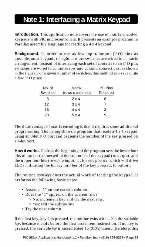
Background. In order to use as few input/output (I/O) pins aspossible, most keypads of eight or more switches are wired in a matrixarrangement. Instead of interfacing each set of contacts to an I/O pin,switches are wired to common row and column connections, as shownin the figure. For a given number of switches, this method can save quitea few I/O pins:
The disadvantage of matrix encoding is that it requires some additionalprogramming. The listing shows a program that reads a 4 x 4 keypadusing an 8-bit I/O port and presents the number of the key pressed ona 4-bit port.
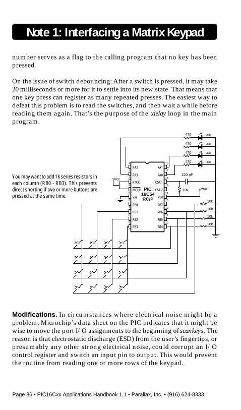
How it works. Code at the beginning of the program sets the lower fourbits of port RB (connected to the columns of the keypad) to output, andthe upper four bits (rows) to input. It also sets port RA, which will driveLEDs indicating the binary number of the key pressed, to output.
The routine scankeys does the actual work of reading the keypad. Itperforms the following basic steps:
• Assert a “1” on the current column.• Does the “1” appear on the current row?
> No: increment key and try the next row.> Yes: exit the subroutine.
• Try the next column.
If the first key, key 0, is pressed, the routine exits with a 0 in the variablekey, because it ends before the first increment instruction. If no key ispressed, the variable key is incremented 16 (010h) times. Therefore, this
Matrix(rows x columns)
I/O PinsRequired
8 2 x 4 6
12 3 x 4 716 4 x 4 820 5 x 4 9
No. ofSwitches
Page 86 • PIC16Cxx Applications Handbook 1.1 • Parallax, Inc. • (916) 624-8333
Note 1: Interfacing a Matrix Keypad
number serves as a flag to the calling program that no key has beenpressed.
On the issue of switch debouncing: After a switch is pressed, it may take20 milliseconds or more for it to settle into its new state. That means thatone key press can register as many repeated presses. The easiest way todefeat this problem is to read the switches, and then wait a while beforereading them again. That’s the purpose of the :delay loop in the mainprogram.
Modifications. In circumstances where electrical noise might be aproblem, Microchip’s data sheet on the PIC indicates that it might bewise to move the port I/O assignments to the beginning of scankeys. Thereason is that electrostatic discharge (ESD) from the user’s fingertips, orpresumably any other strong electrical noise, could corrupt an I/Ocontrol register and switch an input pin to output. This would preventthe routine from reading one or more rows of the keypad.
PIC16C54RC/P
1
2
3
4
5
6
7
8
9
18
17
16
15
14
13
12
11
10
RA2
RA3
RTCC
MCLR
Vss
RB0
RB1
RB2
RB3
RA1
RA0
OSC1
OSC2
Vdd
RB7
RB6
RB5
RB4
Vcc
10k
220 pF
Vcc
10k
10k
10k
10k
470
470
470
470
LED
LED
LED
LED
You may want to add 1k series resistors ineach column (RB0 - RB3). This preventsdirect shorting if two or more buttons arepressed at the same time.
PIC16Cxx Applications Handbook 1.1 • Parallax, Inc. • (916) 624-8333 • Page 87
A milder zap could conceivably cause a false input to the keypad. Someroutines check for this condition by comparing two or more consecutivereadings of the keys. Unless several readings match, no data is returnedto the main program.
Program listing. This program may be downloaded from the ParallaxBBS as KEYPAD.SRC. You can reach the BBS at (916) 624-7101.
Note 1: Interfacing a Matrix Keypad
; PROGRAM: KEYPAD; This program demonstrates a simple method for scanning a matrix-encoded; keypad. The 4 columns of the pad are connected to RB.0 through RB.3; 4 rows to; RB.4 through RB.7. The scanning subroutine returns the code of key pressed; (0h—0Fh) in the variable key. If no switch is pressed, the out-of-range value 10h is; returned in key (this avoids the use of a separate flag variable).
keypad = rbrow1 = rb.4row2 = rb.5row3 = rb.6row4 = rb.7
; Variable storage above special-purpose registers.org 8
cols ds 1key ds 1index ds 1
; Remember to change device info if programming a different PIC.device pic16c54,rc_osc,wdt_off,protect_offreset start
; Set starting point in program ROM to zero.org 0
start mov !rb, #11110000b ; cols out, rows inmov !ra, #0 ; ra all outputs
:keys call scankeyscje key, #16, :delaymov ra, key
:delay nopnopdjnz index,:delaygoto :keys
; Subroutine to scan the keypad. Assumes that the calling routine will delay long; enough for debounce.scankeys clr key
Page 88 • PIC16Cxx Applications Handbook 1.1 • Parallax, Inc. • (916) 624-8333
clr keypadmov cols,#4 ; 4 x 4 keypadsetb c ; put a 1 into carry
; On the first time through the following loop, the carry bit (1) is pulled into keypad.; On subsequent loops, the lone 1 moves across the column outputs.:scan rl keypad
clrb c ; follow the 1 with zerosjb row1, press
; If a 1 is detected, quit the routine with the current value of key. If row1, column1 is; pressed, the value of key is 0 (on the first loop). If not, increment key and try the; next row.
inc keyjb row2, pressinc keyjb row3, pressinc keyjb row4, pressinc keydjnz cols, :scan ; Try all 4 columns.
press ret ; Return with value in key.
; If no key is pressed, the value will be 10h due to execution of the final increment; instruction. The program should interpret this out-of-range value as ‘no press.’
Note 1: Interfacing a Matrix Keypad

PIC16Cxx Applications Handbook 1.1 • Parallax, Inc. • (916) 624-8333 • Page 89
BLANK PAGE

Page 90 • PIC16Cxx Applications Handbook 1.1 • Parallax, Inc. • (916) 624-8333
BLANK PAGE
PIC16Cxx Applications Handbook 1.1 • Parallax, Inc. • (916) 624-8333 • Page 91
Note 2: Receiving RS-232 Serial Data
Introduction. This application note presents a simple program forreceiving asynchronous serial data with PIC microcontrollers. Theexample program, written using Parallax assembly language, displaysreceived bytes on a bank of eight LEDs.
Background. Many controller applications involve receiving data orcommands from a larger system. The RS-232 serial port is a nearlyuniversal means for this communication. While the PIC lacks the serialreceive function found on some more expensive chips, it can readily beprogrammed to receive serial data.
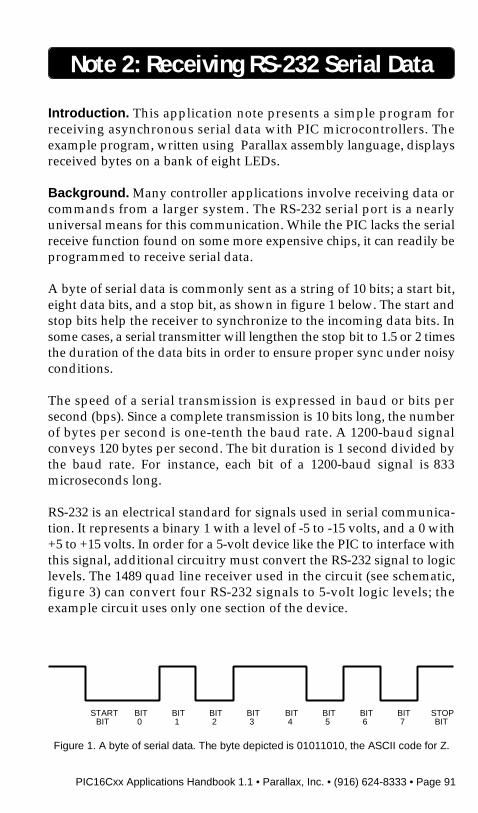
A byte of serial data is commonly sent as a string of 10 bits; a start bit,eight data bits, and a stop bit, as shown in figure 1 below. The start andstop bits help the receiver to synchronize to the incoming data bits. Insome cases, a serial transmitter will lengthen the stop bit to 1.5 or 2 timesthe duration of the data bits in order to ensure proper sync under noisyconditions.
The speed of a serial transmission is expressed in baud or bits persecond (bps). Since a complete transmission is 10 bits long, the numberof bytes per second is one-tenth the baud rate. A 1200-baud signalconveys 120 bytes per second. The bit duration is 1 second divided bythe baud rate. For instance, each bit of a 1200-baud signal is 833microseconds long.
RS-232 is an electrical standard for signals used in serial communica-tion. It represents a binary 1 with a level of -5 to -15 volts, and a 0 with+5 to +15 volts. In order for a 5-volt device like the PIC to interface withthis signal, additional circuitry must convert the RS-232 signal to logiclevels. The 1489 quad line receiver used in the circuit (see schematic,figure 3) can convert four RS-232 signals to 5-volt logic levels; theexample circuit uses only one section of the device.
Figure 1. A byte of serial data. The byte depicted is 01011010, the ASCII code for Z.
STARTBIT
BIT0
BIT1
BIT2
BIT3
BIT4
BIT5
BIT6
BIT7
STOPBIT
Page 92 • PIC16Cxx Applications Handbook 1.1 • Parallax, Inc. • (916) 624-8333
Where cost or space is a problem, the PIC can accept the RS-232 signalthrough a 22k resistor, as shown in the inset to figure 3. The resistorlimits the input current, while the PIC’s internal clamping diodes(intended to protect against static electricity) clip the voltage to logiclevels. The resistor method does not invert the RS-232 signal, so threeminor changes to the program are required as shown in comments tolisting 1. The method also gives up the noise rejection built into the 1489,and should not be used in noisy environments or over long cable runs.
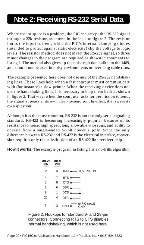
The example presented here does not use any of the RS-232 handshak-ing lines. These lines help when a fast computer must communicatewith (for instance) a slow printer. When the receiving device does notuse the handshaking lines, it is necessary to loop them back as shownin figure 2. That way, when the computer asks for permission to send,the signal appears at its own clear-to-send pin. In effect, it answers itsown question.
Although it is the most common, RS-232 is not the only serial-signalingstandard. RS-422 is becoming increasingly popular because of itsresistance to noise, high speed, long allowable wire runs, and ability tooperate from a single-ended 5-volt power supply. Since the onlydifference between RS-232 and RS-422 is the electrical interface, conver-sion requires only the substitution of an RS-422 line receiver chip.
How it works. The example program in listing 1 is a no-frills algorithm
Note 2: Receiving RS-232 Serial Data
Figure 2. Hookups for standard 9- and 28-pinconnectors. Connecting RTS to CTS disablesnormal handshaking, which is not used here.
RTS
CTS
DSR
DCD
DTR
to PIC circuitGND
to SERIAL INDATA
GND
DB-25PIN
DB-9PIN
2 3
4 7
5 8
6 6
8 1
20 4
7 3

PIC16Cxx Applications Handbook 1.1 • Parallax, Inc. • (916) 624-8333 • Page 93
for receiving serial data in the popular N81 format; i.e., no parity bit,eight data bits, and one stop bit. Listing 2 is a BASIC program forsending individual bytes to the circuit.
Listing 1 begins by setting up the input and output bits. It then entersa loop waiting to detect the start bit. Once the start bit is detected, theprogram waits one-half bit time and checks to see whether the start bitis still present. This helps ensure that the program isn’t fooled by a noiseburst into trying to receive a nonexistent transmission. It also makessure that subsequent bits are read during the middle of their time slots;another precaution against noise.
Once it detects and verifies the start bit, the program enters another loopthat does the actual job of receiving the data. It works like this:
• Wait one bit time.• Copy input bit to carry bit.• Rotate the receive byte right.• Decrement the bit counter.• Is the counter zero?
> No, loop again.> Yes, exit the loop.
If you are unfamiliar with the rotate right (rr) instruction, you may notsee how the input bit gets from the carry bit into the receive byte.Performing an rr on a byte moves its bits one space to the right. Bit 7 goesto bit 6, bit 6 to bit 5, and so on. Bit 0 is moved into the carry bit. The carrybit moves into bit 7.
Once the byte is received, the program waits a final bit delay (until themiddle of the stop bit), copies the received byte to the output port towhich the LEDs are connected, and goes back to the beginning to awaitanother start bit.
The program can be set up for most standard data rates. The table listsPIC clock speeds and values of the bit time constant bit_K (declared atthe beginning of listing 1) for a wide range of common rates. For othercombinations of clock speed and data rate, just replace the delayroutines with ones that provide the appropriate timing. The footnote tothe table gives general guidance.
Note 2: Receiving RS-232 Serial Data

Page 94 • PIC16Cxx Applications Handbook 1.1 • Parallax, Inc. • (916) 624-8333
One final hardware note: Although timing isn’t overly critical forreceiving this type of serial data, resistor/capacitor timing circuits areinadequate. The PIC’s RC clock is specified to fairly loose tolerances (upto ±28 percent) from one unit to another. The values of commonresistors and capacitors can vary substantially from their markedvalues, and can change with temperature and humidity. Always use aceramic resonator or crystal in applications involving serial communi-cation.
Program listing. This program may be downloaded from the ParallaxBBS as RCV232.SRC. You can reach the BBS at (916) 624-7101.
Note 2: Receiving RS-232 Serial Data
LED470
LED470
LED470
PIC16C54
1
2
3
4
5
6
7
8
9
18
17
16
15
14
13
12
11
10
RA2
RA3
RTCC
MCLR
Vss
RB0
RB1
RB2
RB3
RA1
RA0
OSC1
OSC2
Vdd
RB7
RB6
RB5
RB4
+5
+5
47pF
RS-232serial in 13
12
11
1/4 MC1489A:pins 1, 4, 7, 10 to gnd; pin 14 to+5 Vdc; rest not connected.
LED470
LED470
LED470
LED470
LED470
ceramic resonatorw/integral capacitors
A 22k resistor may be usedinstead of the 1489. Changethe program as marked inlisting 1.
1RA2
RS-232serial in
22k
Figure 3.Schematic to
accompanyRCV232.SRC.

PIC16Cxx Applications Handbook 1.1 • Parallax, Inc. • (916) 624-8333 • Page 95
Note 2: Receiving RS-232 Serial Data
Values of Timing Constant Bit_K for Various Clock Speeds and Bit Rates
ClockSerial Bit Rate (bit time)
Frequency600 1200 2400 4800 9600 19,200
1 MHz 206 102 50 24 — — —2 MHz — 206 102 50 24 — —4 MHz — — 206 102 50 24 —8 MHz — — — 206 102 50 24
Other combinations of clock speed and bit rate can be supported by changing the bit_delay and
start_delay subroutines. The required bit delay is 1bit rate
. For example, at 1200 baud the bit delay
is 11200
= 833µs. The start delay is half of the bit delay; 416µs for the 1200-baud example.
Calculate the time delay of a subroutine by adding up its instruction cycles and multiplying by4
clock speed. At 2 MHz, the time per instruction cycle is 4
2 ,000 ,000 = 2µs.
300(3.33 ms) (1.66 ms) (833 µs) (417 µs) (208 µs) (104 µs) (52 µs)
; PROGRAM: RCV232; This program receives a byte of serial data and displays it on eight LEDs; connected to port RB. The receiving baud rate is determined by the value of the; constant bit_K and the clock speed of the PIC. See the table in the application note; (above) for values of bit_K. For example, with the clock running at 4 MHz and a; desired receiving rate of 4800 baud, make bit_K 50.
bit_K = 24 ; Change this value for desired; baud rate as shown in table.
half_bit = bit_K/2serial_in = ra.2data_out = rb
; Variable storage above special-purpose registers.org 8
delay_cntr ds 1 ; counter for serial delay routinesbit_cntr ds 1 ; number of received bitsrcv_byte ds 1 ; the received byte
; Org 0 sets ROM origin to beginning for program.org 0
; Remember to change device info if programming a different PIC. Do not use RC; devices. They are not sufficiently accurate or stable for serial communication.
device pic16c54,xt_osc,wdt_off,protect_offreset begin
; Set up I/O ports.
begin mov !ra, #00000100b ; Use RA.2 for serial input.
Page 96 • PIC16Cxx Applications Handbook 1.1 • Parallax, Inc. • (916) 624-8333
mov !rb, #0 ; Output to LEDs.
:start_bit snb serial_in ; Detect start bit. Change to sb; serial_in if using 22k resistor; input.
jmp :start_bit ; No start bit yet? Keep watching.call start_delay ; Wait one-half bit time to the
; middle of the start bit.
jb Serial_in, :start_bit ; If the start bit is still good,; continue. Otherwise, resume; waiting.
; Change to jnb Serial_in, :start_bit; if using 22k resistor input.
mov bit_cntr, #8 ; Set the counter to receive 8 data; bits.
clr rcv_byte ; Clear the receive byte to get; ready for new data.
:receive call bit_delay ; Wait one bit time.movb c,Serial_in ; Put the data bit into carry.
; Change to movb c,/Serial_in if; using 22k resistor input.
rr rcv_byte ; Rotate the carry bit into the; receive byte.
djnz bit_cntr,:receive ; Not eight bits yet? Get next bit.call bit_delay ; Wait for stop bit.mov data_out, rcv_byte ; Display data on LEDs.
goto begin:start_bit ; Receive next byte.
; This delay loop takes four instruction cycles per loop, plus eight instruction cycles; for other operations (call, mov, the final djnz, and ret). These extra cycles become; significant at higher baud rates. The values for bit_K in the table take the time; required for additional instructions into account.
bit_delay mov delay_cntr,#bit_K:loop nop
djnz delay_cntr, :loopret
; This delay loop is identical to bit_delay above, but provides half the delay time.
start_delay mov delay_cntr,#half_bit
Note 2: Receiving RS-232 Serial Data
PIC16Cxx Applications Handbook 1.1 • Parallax, Inc. • (916) 624-8333 • Page 97
Note 2: Receiving RS-232 Serial Data
:loop nopdjnz delay_cntr, :loopret
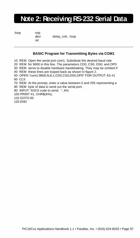
BASIC Program for Transmitting Bytes via COM1
10 REM Open the serial port com1. Substitute the desired baud rate20 REM for 9600 in this line. The parameters CD0, CS0, DS0, and OP030 REM serve to disable hardware handshaking. They may be omitted if40 REM these lines are looped back as shown in figure 2.50 OPEN “com1:9600,N,8,1,CD0,CS0,DS0,OP0” FOR OUTPUT AS #160 CLS70 REM At the prompt, enter a value between 0 and 255 representing a80 REM byte of data to send out the serial port.90 INPUT “ASCII code to send: “, A%100 PRINT #1, CHR$(A%);110 GOTO 60120 END

Page 98 • PIC16Cxx Applications Handbook 1.1 • Parallax, Inc. • (916) 624-8333
BLANK PAGE

PIC16Cxx Applications Handbook 1.1 • Parallax, Inc. • (916) 624-8333 • Page 99
Note 3: Sending RS-232 Serial Data
Introduction. This application note covers transmission of asynchro-nous serial data using PIC microcontrollers. It presents an exampleprogram in Parallax assembly language that transmits a text stringserially via RS-232 at speeds up to 19,200 bits per second. Hardwareexamples demonstrate the use of a popular serial line driver, as well asa method for using the PIC’s output to directly drive a serial line.
Background. Many PIC applications require sending data to a largercomputer system. The common RS-232 serial port is almost ideal for thiscommunication. While the PIC lacks the onboard serial communicationhardware available with some more expensive controllers, it can readilybe programmed to add this capability.
A previous application note (#2, Receiving RS-232 Serial Data) coveredthe data format and RS-232 signals in some detail. Here are the high-lights:
A byte of serial data is commonly sent as 10 bits: a start bit, eight databits, and a stop bit. The duration of these bits is calculated by dividing
1k
Reset
MAX232
1
2
3
4
5
6
7
8
16
15
14
13
12
11
10
9
C1+
+10
C1-
C2+
C2-
-10
X2 out
R2 in
Vcc
GND
X1 out
R1 in
R1 out
X1 in
X2 in
R2 out
+5
10 µF
PIC16C54
1
2
3
4
5
6
7
8
9
18
17
16
15
14
13
12
11
10
RA2
RA3
RTCC
MCLR
Vss
RB0
RB1
RB2
RB3
RA1
RA0
OSC1
OSC2
Vdd
RB7
RB6
RB5
RB4
+5
ceramic resonatorw/integral capacitors
RS-232serial out
10 µF
10 µF
10 µF
10 µF
The PIC's output may be connecteddirectly to the serial input of theterminal or PC. Change the programas marked in listing 1.
RS-232serial out
1RA2
+5
Page 100 • PIC16Cxx Applications Handbook 1.1 • Parallax, Inc. • (916) 624-8333
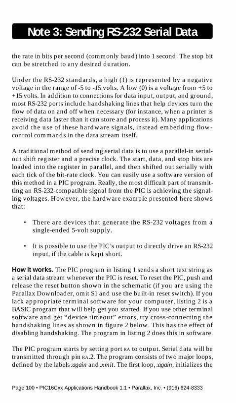
the rate in bits per second (commonly baud) into 1 second. The stop bitcan be stretched to any desired duration.
Under the RS-232 standards, a high (1) is represented by a negativevoltage in the range of -5 to -15 volts. A low (0) is a voltage from +5 to+15 volts. In addition to connections for data input, output, and ground,most RS-232 ports include handshaking lines that help devices turn theflow of data on and off when necessary (for instance, when a printer isreceiving data faster than it can store and process it). Many applicationsavoid the use of these hardware signals, instead embedding flow-control commands in the data stream itself.
A traditional method of sending serial data is to use a parallel-in serial-out shift register and a precise clock. The start, data, and stop bits areloaded into the register in parallel, and then shifted out serially witheach tick of the bit-rate clock. You can easily use a software version ofthis method in a PIC program. Really, the most difficult part of transmit-ting an RS-232-compatible signal from the PIC is achieving the signal-ing voltages. However, the hardware example presented here showsthat:
• There are devices that generate the RS-232 voltages from asingle-ended 5-volt supply.
• It is possible to use the PIC’s output to directly drive an RS-232input, if the cable is kept short.
How it works. The PIC program in listing 1 sends a short text string asa serial data stream whenever the PIC is reset. To reset the PIC, push andrelease the reset button shown in the schematic (if you are using theParallax Downloader, omit S1 and use the built-in reset switch). If youlack appropriate terminal software for your computer, listing 2 is aBASIC program that will help get you started. If you use other terminalsoftware and get “device timeout” errors, try cross-connecting thehandshaking lines as shown in figure 2 below. This has the effect ofdisabling handshaking. The program in listing 2 does this in software.
The PIC program starts by setting port RA to output. Serial data will betransmitted through pin RA.2. The program consists of two major loops,defined by the labels :again and :xmit. The first loop, :again, initializes the
Note 3: Sending RS-232 Serial Data

PIC16Cxx Applications Handbook 1.1 • Parallax, Inc. • (916) 624-8333 • Page 101
bit counter, and then gets a byte from the subroutine/table called string.Once string returns a byte in the w register, the program puts this byteinto xmt_byte. After a start bit is sent by clearing the serial-out pin, :xmittakes over. It performs the following steps:
• Rotate the transmit byte right (into carry).• Move the carry bit to serial output.• Wait one bit time (set by bit_K).• Decrement the bit counter.• Is the counter zero?
> No, loop again.> Yes, exit the loop.
With the :xmit loop finished, the program sets the serial-out pin to senda stop bit, and checks to see whether it has reached the end of the string.If not, it goes back to :again to retrieve another byte. If it is done with thestring, the program enters an endless loop.
The hardware portion of the application is fairly straightforward. ThePIC produces logic-level signals that the MAX232 chip converts toacceptable RS-232 levels, approximately ±10 volts. The MAX232 hasonboard charge-pumps that use the external capacitors to build up therequired signaling voltages. There are other chips that provide addi-
Note 3: Sending RS-232 Serial Data
Figure 2. Hookups for standard 9- and 28-pinconnectors. Connecting RTS to CTS disablesnormal handshaking, which is not used here.
RTS
CTS
DSR
DCD
DTR
to PIC circuitGND
to SERIAL OUTDATA
GND
DB-25PIN
DB-9PIN
3 2
4 7
5 8
6 6
8 1
20 4
7 3

Page 102 • PIC16Cxx Applications Handbook 1.1 • Parallax, Inc. • (916) 624-8333
tional features, such as additional I/O channels, higher signaling rates,lower power consumption, and the ability to work without externalcapacitors.
Modifications. The MAX232 draws more current and costs more (insingle-part quantities) than the PIC it supports. Most of the time, this isstill a bargain compared to adding a bipolarity power supply to a devicejust to support RS-232 signaling. In fact, the MAX232 has excess currentcapacity that can be used to power other small bipolarity devices, suchas low-power op-amps. Depending on the application, additionalvoltage regulation may be required.
If you plan to use the serial port infrequently, consider powering theMAX chip through one of the PIC’s I/O pins. Your program could turnthe MAX on shortly before it needed to send a serial message, and turnit back off afterward. This option is especially attractive for uses thatrequire wringing the most life out of a set of batteries.
A sample MAX232 that we tested drew 15 mA while driving twosimulated serial-port loads. This is well within the PIC’s drive capabil-ity. A further test showed that the MAX232’s output voltages rose totheir full ±10-volt levels about 1.5 milliseconds after power was appliedto the chip. If your program switches the MAX232 on and off, programa 1.5-ms delay between turning the device on and sending the first bit.
In some cases, you may be able to dispense with the serial line driveraltogether. Make the changes marked in listing 1 “for direct connec-tion” and wire RA.2 directly to the serial receive connection of yourterminal or PC. The changes in the program invert the logic of the serialbits, so that a 1 is represented by an output of 0 volts and a 0 is a 5-voltoutput. According to RS-232, the receiving device should expect volt-ages of at least -3 volts for a 1 and +3 volts for a 0. Voltages lying between+3 and -3 are undefined, meaning they could go either way and stillcomply with the standard.
As a practical matter, though, it wouldn’t be smart to let 0 volts beinterpreted as a 0, since this is a serial start bit. Any time the serial inputwas at ground potential, the terminal or PC would attempt to receiveincoming serial data. This would cause plenty of false receptions.Serial-port designers apparently take this into account and set the 0threshold somewhere above ground.
Note 3: Sending RS-232 Serial Data

PIC16Cxx Applications Handbook 1.1 • Parallax, Inc. • (916) 624-8333 • Page 103
Note 3: Sending RS-232 Serial Data
That’s why this cheap trick works. Don’t count on it to provide full RS-232 performance, especially when it comes to sending data rapidly overlong cables. Keep cables short and you shouldn’t have any problems(19,200 baud seems to work error-free through 6 feet of twisted pair).
If your application will have access to the handshaking pins, you maybe able to steal enough power from them to eliminate batteries entirely.According to the RS-232 specifications, all signals must be capable ofoperating into a 3000-ohm load. Since many computers use ±12 volts fortheir RS-232 signals, each line should be capable of delivering 4 mA. Inpractice, most can provide more, up to perhaps 15 mA. The onlyproblem with exploiting this free power is that the software running onthe PC or terminal must be written or modified to keep the handshakinglines in the required state.
One final hardware note: Although timing isn’t overly critical fortransmitting serial data, resistor/capacitor timing circuits are inad-equate. The PIC’s RC clock is specified to fairly loose tolerances (up to±28 percent) from one unit to another. The values of common resistorsand capacitors can vary substantially from their marked values, andcan change with temperature and humidity. Always use a ceramicresonator or crystal in applications involving serial communication.
Program listing. This program may be downloaded from the ParallaxBBS as XMIT232.SRC. You can reach the BBS at (916) 624-7101.
ClockSerial Bit Rate (bit time)
Frequency600 1200 2400 4800 9600 19,200
1 MHz 206 102 50 24 — — —2 MHz — 206 102 50 24 — —4 MHz — — 206 102 50 24 —8 MHz — — — 206 102 50 24
Other combinations of clock speed and bit rate can be supported by changing the bit_delay and
start_delay subroutines. The required bit delay is 1bit rate
. For example, at 1200 baud the bit delay
is 11200
= 833µs. The start delay is half of the bit delay; 416µs for the 1200-baud example.
Calculate the time delay of a subroutine by adding up its instruction cycles and multiplying by4
clock speed. At 2 MHz, the time per instruction cycle is 4
2 ,000 ,000 = 2µs.
300(3.33 ms) (1.66 ms) (833 µs) (417 µs) (208 µs) (104 µs) (52 µs)
Values of Timing Constant Bit_K for Various Clock Speeds and Bit Rates

Page 104 • PIC16Cxx Applications Handbook 1.1 • Parallax, Inc. • (916) 624-8333
Note 3: Sending RS-232 Serial Data
; PROGRAM: XMIT232; This program transmits a string of serial data. The baud rate is determined by the; value of the constant bit_K and the clock speed of the PIC. See the table in the; application note (above) for values of bit_K. For example, with the clock running at; 4 MHz and a desired transmitting rate of 4800 baud, make bit_K 50.
bit_K = 24 ; 24 for 19,200-baud operation @ 8 MHzserial_out = ra.2
; Variable storage above special-purpose registers.org 8
delay_cntr ds 1 ; counter for serial delay routinesbit_cntr ds 1 ; number of transmitted bitsmsg_cntr ds 1 ; offset in stringxmt_byte ds 1 ; the transmitted byte
; Org 0 sets ROM origin to beginning for program.org 0
; Remember to change device info if programming a different PIC. Do not use RC; devices. They are not sufficiently accurate or stable for serial communication.
device pic16c54,xt_osc,wdt_off,protect_offreset begin
begin mov !ra, #00000000b ; Set port to output.mov msg_cntr, #0 ; Message string has nine
; characters; 0 through 8.:again mov bit_cntr,#8 ; Eight bits in a byte.
mov w,msg_cntr ; Point to position in the string.call string ; Get next character from string.mov xmt_byte,w ; Put character into transmit byte.clrb serial_out ; Change to setb serial_out for
; direct connection.call bit_delay ; Start bit.
:xmit rr xmt_byte ; Rotate right moves data bits into; carry, starting with bit 0.
movb serial_out,c ; Change to movb serial_out,/c for; direct connection.
call bit_delay ; Data bit.djnz bit_cntr,:xmit ; Not eight bits yet? Send next bit.setb serial_out ; Change to clrb serial_out for
; direct connectioncall bit_delay ; Stop bit.inc msg_cntr ; Add one to the string pointer.cjbe msg_cntr,#8, :again ; More characters to send? Go to
; the top.
:endless goto :endless ; Endless loop. Reset controller to; run program.
PIC16Cxx Applications Handbook 1.1 • Parallax, Inc. • (916) 624-8333 • Page 105
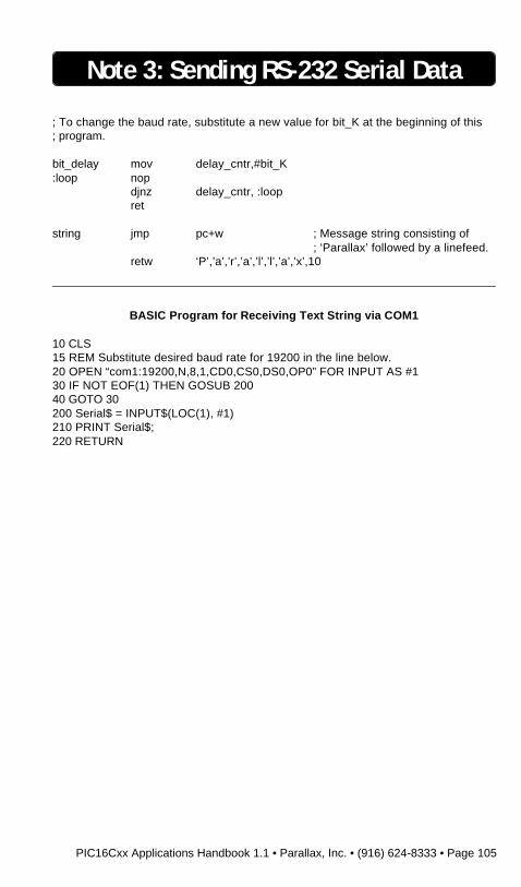
; To change the baud rate, substitute a new value for bit_K at the beginning of this; program.
bit_delay mov delay_cntr,#bit_K:loop nop
djnz delay_cntr, :loopret
string jmp pc+w ; Message string consisting of; ‘Parallax’ followed by a linefeed.
retw ‘P’,’a’,’r’,’a’,’l’,’l’,’a’,’x’,10
Note 3: Sending RS-232 Serial Data
BASIC Program for Receiving Text String via COM1
10 CLS15 REM Substitute desired baud rate for 19200 in the line below.20 OPEN “com1:19200,N,8,1,CD0,CS0,DS0,OP0” FOR INPUT AS #130 IF NOT EOF(1) THEN GOSUB 20040 GOTO 30200 Serial$ = INPUT$(LOC(1), #1)210 PRINT Serial$;220 RETURN

Page 106 • PIC16Cxx Applications Handbook 1.1 • Parallax, Inc. • (916) 624-8333
BLANK PAGE
PIC16Cxx Applications Handbook 1.1 • Parallax, Inc. • (916) 624-8333 • Page 107
Note 4: Reading Rotary Encoders
Introduction. This application note covers the use of incrementalrotary encoders with PIC microcontrollers. It presents an exampleprogram in Parallax assembly language for reading a typical encoderand displaying the results as an up/down count on a seven-segmentLED display.
Background. Incremental rotary encoders provide a pair of digitalsignals that allow a microcontroller to determine the speed and direc-tion of a shaft’s rotation. They can be used to monitor motors andmechanisms, or to provide a control-knob user interface. The best-known application for rotary encoders is the mouse, which containstwo encoders that track the x- and y-axis movements of a ball in thedevice’s underside.
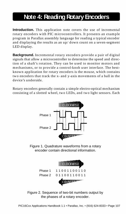
Rotary encoders generally contain a simple electro-optical mechanismconsisting of a slotted wheel, two LEDs, and two light sensors. Each
Figure 2. Sequence of two-bit numbers output bythe phases of a rotary encoder.
0 1 1 0 0 1 1 0 0 1 1
CLOCKWISE
COUNTER CW
Phase 1Phase 2
1 1 0 0 1 1 0 0 1 1 0
Figure 1. Quadrature waveforms from a rotaryencoder contain directional information.
CLOCKWISE
COUNTER CW
Phase 1
Phase 2

Page 108 • PIC16Cxx Applications Handbook 1.1 • Parallax, Inc. • (916) 624-8333
LED/sensor pair is arranged so that the devices face each other throughthe slots in the wheel. As the wheel turns, it alternately blocks andpasses light, resulting in square wave outputs from the sensors.
The LED/sensor pairs are mounted offset relative to one another, sothat the output square waves are offset 90 degrees in phase. This isknown as quadrature, because 90 degrees amount to one-quarter of afull 360-degree cycle.
This phase relationship provides the information needed to determinethe encoder’s direction of rotation (see figure 1).
The dotted lines in figure 1 indicate a common method of reading
Note 4: Reading Rotary Encoders
PIC16C54
1
2
3
4
5
6
7
8
9
18
17
16
15
14
13
12
11
10
RA2
RA3
RTCC
MCLR
Vss
RB0
RB1
RB2
RB3
RA1
RA0
OSC1
OSC2
Vdd
RB7
RB6
RB5
RB4
Vcc
NC 10k
220 pF
Vcc
470
470
470
470
470
470
470
NC
Vcc
V+
gnd
p1p2
Rotary Encoder(Digi-Key GH6102)
1k 1k
14
56
a
b
c
d
e
f
g
b
c
d
e
f
g
a
Common-CathodeLED Display

PIC16Cxx Applications Handbook 1.1 • Parallax, Inc. • (916) 624-8333 • Page 109
direction. For instance, if phase 1 is high and phase 2 is rising, thedirection is clockwise (CW). If phase 1 is low and phase 2 is rising, thedirection is counterclockwise (CCW).
For the sake of interpreting this output with a PIC or othermicrocontroller, it’s probably more useful to look at the changing statesof the phases as a series of two-bit numbers, as shown in figure 2 above.
When the encoder shaft is turning CW, you get a different sequence ofnumbers (01,00,10,11) than when it is turning CCW (01,11,10,00). Youmay recognize this sequence as Gray code. It is distinguished by the factthat only one bit changes in any transition. Gray code produces noincorrect intermediate values when the count rolls over. In normalbinary counting, 11 rolls over to 00. If one bit changed slightly before theother, the intermediate number value could be incorrectly read as 01 or10 before settling into the correct state of 00.
Interpreting this code amounts to comparing the incoming sequence tothe known sequences for CW and CCW rotation. A lookup table woulddo the trick. However, this approach, while easy to understand, isinefficient. The shortcut method uses an interesting property of thetwo-bit Gray code sequence.
Pick any pair of two-bit numbers from the CW sequence shown infigure 2; for instance, the first two: 10, 11. Compute the exclusive-OR(XOR) of the righthand bit of the first number with the lefthand bit ofthe second. In this case, that would be 0 XOR 1 = 1. Try this for any CWpair of numbers from the table, and you’ll always get 1.Now reverse the order of the number pair: 11, 10. XOR the right bit ofthe first with the left of the second (1 XOR 1 = 0). Any CCW pair ofnumbers will produce a 0.
How it works. The schematic in figure 3 shows a typical rotary encoderconnected to the lower two bits of port RA, and a seven-segment LEDdisplay to port RB. The circuit, and the program in the listing, performa simple task. The count displayed on the LED goes up when the controlis turned CW, and down when it is turned CCW. The display is inhexadecimal, using seven-segment approximations of the letters: A, b,C, d, E F.
Note 4: Reading Rotary Encoders
Page 110 • PIC16Cxx Applications Handbook 1.1 • Parallax, Inc. • (916) 624-8333
The program begins by setting up the I/O ports and clearing thevariable counter. It gets an initial input from the encoder, which goesinto the variable old, and strips off all but the two least-significant bits(LSBs).
The body of the program, starting with :loop, calls check_encoder andthen displays the latest value of counter on the LED display.
Most of the interesting business happens in check_encoder itself. Here,the program gets the latest value at the encoder inputs, strips all but thetwo LSBs, and XORs the result into a copy of the old value. If the resultis zero, the encoder hasn’t moved since its last reading, and the routinereturns without changing the value of counter.
If the value has changed, the routine moves the value in old one bit to theleft in order to align its LSB with the high bit of the two-bit value in new.It XORs the variables together. It then examines the bit old.1. If the bit is1, counter is incremented; if it’s 0, counter is decremented.
Modifications. To avoid ‘slippage’ errors (where a change in encoderposition does not change the counter, or results in the wrong change),check_encoder must be called at least once every 1/(encoder resolution
* max revs per second). For instance, if the encoder might turn 300 rpm
(5 revs per second) and its resolution is 32 transitions per turn,check_encoder must be called every 1/(32
*5) seconds, or 6.25 millisec-
onds. For a user interface, bear in mind that generally the larger theknob, the slower the input. Substitution of a larger control knob may beall that’s required to reduce the sampling rate.
In circumstances where electrical noise might be a problem, Microchip’sPIC data sheet indicates that it might be wise to move the port I/Oassignments to the beginning of check_encoder. Electrostatic discharge(ESD) from the user’s fingertips, or some other electrical noise, couldcorrupt an I/O control register. This would prevent the routine fromreading the encoder.
Program listing. This program may be downloaded from the ParallaxBBS as RD_ENCDR.SRC. You can reach the BBS at (916) 624-7101.
Note 4: Reading Rotary Encoders
PIC16Cxx Applications Handbook 1.1 • Parallax, Inc. • (916) 624-8333 • Page 111
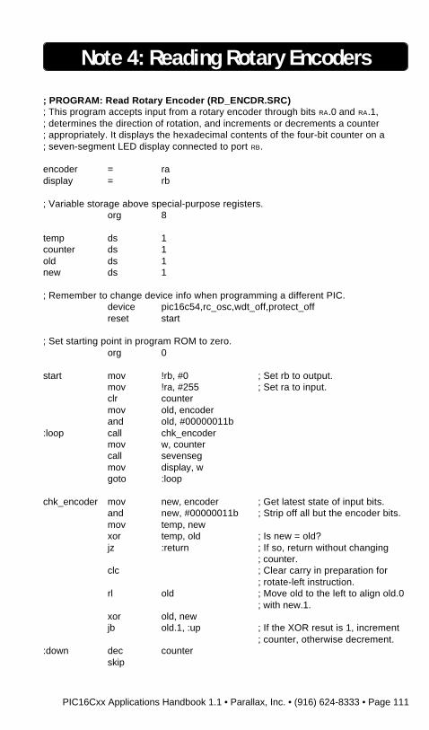
; PROGRAM: Read Rotary Encoder (RD_ENCDR.SRC); This program accepts input from a rotary encoder through bits RA.0 and RA.1,; determines the direction of rotation, and increments or decrements a counter; appropriately. It displays the hexadecimal contents of the four-bit counter on a; seven-segment LED display connected to port RB.
encoder = radisplay = rb
; Variable storage above special-purpose registers.org 8
temp ds 1counter ds 1old ds 1new ds 1
; Remember to change device info when programming a different PIC.device pic16c54,rc_osc,wdt_off,protect_offreset start
; Set starting point in program ROM to zero.org 0
start mov !rb, #0 ; Set rb to output.mov !ra, #255 ; Set ra to input.clr countermov old, encoderand old, #00000011b
:loop call chk_encodermov w, countercall sevensegmov display, wgoto :loop
chk_encoder mov new, encoder ; Get latest state of input bits.and new, #00000011b ; Strip off all but the encoder bits.mov temp, newxor temp, old ; Is new = old?jz :return ; If so, return without changing
; counter.clc ; Clear carry in preparation for
; rotate-left instruction.rl old ; Move old to the left to align old.0
; with new.1.xor old, newjb old.1, :up ; If the XOR resut is 1, increment
; counter, otherwise decrement.:down dec counter
skip
Note 4: Reading Rotary Encoders

Page 112 • PIC16Cxx Applications Handbook 1.1 • Parallax, Inc. • (916) 624-8333
:up inc counterand counter, #00001111bmov old,new
:return ret
sevenseg jmp pc+w ; display lookup tableretw 126, 48, 109, 121, 51, 91, 95, 112retw 127, 115, 119, 31, 78, 61, 79, 71
Note 4: Reading Rotary Encoders

PIC16Cxx Applications Handbook 1.1 • Parallax, Inc. • (916) 624-8333 • Page 113
BLANK PAGE

Page 114 • PIC16Cxx Applications Handbook 1.1 • Parallax, Inc. • (916) 624-8333
BLANK PAGE
PIC16Cxx Applications Handbook 1.1 • Parallax, Inc. • (916) 624-8333 • Page 115
Note 5: Producing Sound & Music
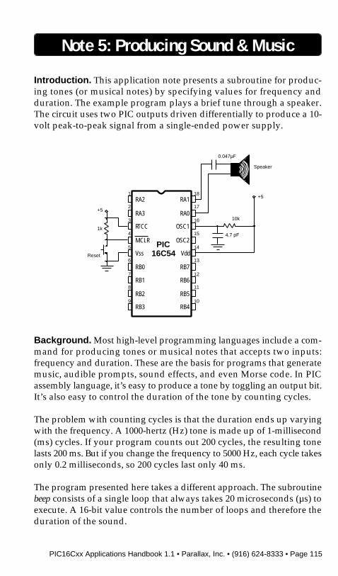
Introduction. This application note presents a subroutine for produc-ing tones (or musical notes) by specifying values for frequency andduration. The example program plays a brief tune through a speaker.The circuit uses two PIC outputs driven differentially to produce a 10-volt peak-to-peak signal from a single-ended power supply.
Background. Most high-level programming languages include a com-mand for producing tones or musical notes that accepts two inputs:frequency and duration. These are the basis for programs that generatemusic, audible prompts, sound effects, and even Morse code. In PICassembly language, it’s easy to produce a tone by toggling an output bit.It’s also easy to control the duration of the tone by counting cycles.
The problem with counting cycles is that the duration ends up varyingwith the frequency. A 1000-hertz (Hz) tone is made up of 1-millisecond(ms) cycles. If your program counts out 200 cycles, the resulting tonelasts 200 ms. But if you change the frequency to 5000 Hz, each cycle takesonly 0.2 milliseconds, so 200 cycles last only 40 ms.
The program presented here takes a different approach. The subroutinebeep consists of a single loop that always takes 20 microseconds (µs) toexecute. A 16-bit value controls the number of loops and therefore theduration of the sound.
PIC16C54
1
2
3
4
5
6
7
8
9
18
17
16
15
14
13
12
11
10
RA2
RA3
RTCC
MCLR
Vss
RB0
RB1
RB2
RB3
RA1
RA0
OSC1
OSC2
Vdd
RB7
RB6
RB5
RB4
+5
10k
4.7 pF
+5
0.047µF
Speaker
1k
Reset
Page 116 • PIC16Cxx Applications Handbook 1.1 • Parallax, Inc. • (916) 624-8333
An eight-bit counter controls the frequency of the sound. If the fre-quency value is 100, then the routine inverts the speaker lines every100th execution of the main loop. The larger the frequency value, thelower the output frequency.
How it works. The circuit in figure 1 plays a short tune each time the PICis powered up or reset (if you are using the Parallax downloader, youcan omit the switch and use the built-in reset button). The speakerconnects through a capacitor to two of the PIC’s input/output pins.Most PIC circuits switch a load between a single pin and ground or +5volts. As a result, the largest voltage swing they can generate is 5 volts.In this case, the program ensures that RA.0 and RA.1 are always comple-mented; when RA.0 is 1, RA.1 is 0 and vice versa. The speaker thereforesees a 10-volt swing. This makes a noticeably louder sound, especiallywith piezo devices, which are more efficient at higher voltages.The program that controls the PIC begins by setting port RA to outputand loading a pattern of alternating 0’s and 1’s into it. The program thenlooks up two values from ROM tables* notes and lengths. It stores thesevalues in the variables freq and duratn, and calls the subroutine beep.
Beep accepts the values and produces a tone of the specified frequencyand duration. The key to this routine is the ability of the exclusive-OR(XOR) logic function to selectively invert bits. XOR’s truth table is:
A XOR B Result0 0 00 1 11 0 11 1 0
When B contains a 0, Result = A. When B contains a 1, Result is theinverse of A.
Note 5: Producing Sound & Music
*You can stuff a series of bytes into the program ROM for later use by your program. Just setup a subroutine beginning with jmp pc+w followed by the directive retw byte0, byte1, byte2...When you need to access one of these numbers from your program, just move the numbercorresponding to the byte value you want into the w register, and call the table. Upon return, thebyte value will be in the w register.

PIC16Cxx Applications Handbook 1.1 • Parallax, Inc. • (916) 624-8333 • Page 117
Each time beep loops, it XOR’s the speaker lines with the variable tgl.Most of the time, this variable contains 0’s, so the XOR has no effect. Thecounter variable f_temp is decremented each time the loop executes.When f_temp reaches 0, tgl gets loaded with 1’s. Now XOR’ing thespeaker lines with tgl inverts them. The routine reloads f_temp with thevalue freq, and the process starts again.
After beep returns, the main program increments the variable index andchecks to see whether all the notes have played. If they haven’t, theprogram loops. If they have, it enters an endless do-nothing loopwaiting to be reset or shut off.
A couple of notes about using beep in other applications: To calculate thevalue freq for a given frequency, divide the frequency in hertz into50,000 (4-MHz clock) or 100,000 (8-MHz clock). If freq is 0, beep willproduce a silent delay of the length set by duratn. To calculate duratn,divide the desired length of the tone by 5 ms.
Modifications. The frequency and duration values that make up thetune CHARGE were programmed by ear, but you can readily program realmusic by using the table below. It lists the three octaves that beepadequately covers. Note that the routine is not always right on thenominal frequency of the notes, but it’s generally within a few hertz.The worst-case error is about 1 percent. The frequencies listed assumea 4-MHz clock. If you use an 8-MHz clock, the values for freq listed in thetable will still accurately represent musical notes, but they’ll be shiftedupward by one octave.
If you use a resistor-capacitor oscillator, your notes could wind upbeing sharp or flat (or worse) because of variations in clock frequency.For applications in which it’s important that the notes sound just right,use a ceramic resonator or crystal.
To program a tune, look up each note in the table and put the corre-sponding freq into notes. To calculate values for lengths, pick an appro-priate duration for a whole note, and scale half-note, quarter-notes,eighths and so on correspondingly. The duration in milliseconds of thenote will be approximately 5 x duratn. So, if you pick a value of 128 fora whole note, it will last 640 ms.
Note 5: Producing Sound & Music

Page 118 • PIC16Cxx Applications Handbook 1.1 • Parallax, Inc. • (916) 624-8333
When you’re done filling in notes and lengths, count the notes and set theconstant end_note equal to this number. Also make sure that the numberof notes is equal to the number of lengths.
Program listing. This program may be downloaded from the ParallaxBBS as CHARGE.SRC. You can reach the BBS at (916) 624-7101.
Note 5: Producing Sound & Music
Values of Variable freq Required to Create Musical Notes (4-MHz clock)
Firs t Oc t av e Sec ond Oc t av e Third Oc t av e
NoteNominal
(Hz)Actual(Hz)
Value offreq
Nominal(Hz)
Actual(Hz)
Value offreq
Nominal(Hz)
Actual(Hz)
Value offreq
A 220 220 227 440 439 114 880 877 57B 247 248 202 494 495 101 988 980 51C 262 262 191 523 521 96 1047 1042 48D 294 294 170 587 588 85 1175 1163 43E 330 329 152 659 658 76 1319 1316 38F 349 350 143 698 694 72 1397 1389 36G 392 391 128 784 781 64 1568 1563 32
*To get values of freq for sharps (#), multiply the value listed by 0.9442 and round off the result.For example, the freq value for C# in the first octave would be 0.9442 x 191 = 180.
; PROGRAM: CHARGE.SRC; This program in Parallax assembly language plays a short tune, “Charge,” from; data stored in a pair of tables. It uses a general-purpose routine called beep to; generate the notes from frequency and duration data. The tune will play when the; PIC or Downloader is first powered up, and any time the device is reset. Note that; although beep uses seven file registers, five of these may be reused elsewhere in; the program for counting, or any use that does not require their values to be; preserved after beep is called.
spkr = ra ; Connect speaker to adjacent rapins.end_note = 6 ; number of notes in the tune
; Variable storage above special-purpose registers.org 8
freq ds 1 ; passess frequency value to beepduratn ds 1 ; passes duration value to beepf_temp ds 1 ; temporary counter (frequency)d_hi ds 1 ; temporary counter (high byte of
; duration)d_lo ds 1 ; temporary counter (low byte of
; duration)tgl ds 1 ; temporary variablet_pat ds 1 ; temporary variableindex ds 1 ; note counter used by main
; program
PIC16Cxx Applications Handbook 1.1 • Parallax, Inc. • (916) 624-8333 • Page 119
Note 5: Producing Sound & Music
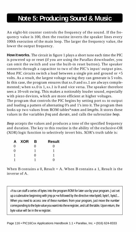
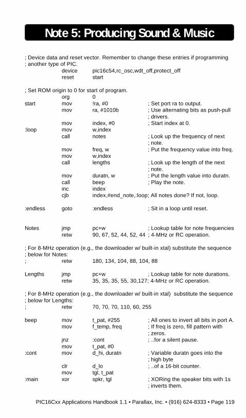
; Device data and reset vector. Remember to change these entries if programming; another type of PIC.
device pic16c54,rc_osc,wdt_off,protect_offreset start
; Set ROM origin to 0 for start of program.org 0
start mov !ra, #0 ; Set port ra to output.mov ra, #1010b ; Use alternating bits as push-pull
; drivers.mov index, #0 ; Start index at 0.
:loop mov w,indexcall notes ; Look up the frequency of next
; note.mov freq, w ; Put the frequency value into freq.mov w,indexcall lengths ; Look up the length of the next
; note.mov duratn, w ; Put the length value into duratn.call beep ; Play the note.inc indexcjb index,#end_note,:loop; All notes done? If not, loop.
:endless goto :endless ; Sit in a loop until reset.
Notes jmp pc+w ; Lookup table for note frequenciesretw 90, 67, 52, 44, 52, 44 ; 4-MHz or RC operation.
; For 8-MHz operation (e.g., the downloader w/ built-in xtal) substitute the sequence; below for Notes:; retw 180, 134, 104, 88, 104, 88
Lengths jmp pc+w ; Lookup table for note durations.retw 35, 35, 35, 55, 30,127; 4-MHz or RC operation.
; For 8-MHz operation (e.g., the downloader w/ built-in xtal) substitute the sequence; below for Lengths:; retw 70, 70, 70, 110, 60, 255
beep mov t_pat, #255 ; All ones to invert all bits in port A.mov f_temp, freq ; If freq is zero, fill pattern with
; zeros.jnz :cont ; ..for a silent pause.mov t_pat, #0
:cont mov d_hi, duratn ; Variable duratn goes into the; high byte
clr d_lo ; ..of a 16-bit counter.mov tgl, t_pat
:main xor spkr, tgl ; XORing the speaker bits with 1s; inverts them.

Page 120 • PIC16Cxx Applications Handbook 1.1 • Parallax, Inc. • (916) 624-8333
:delay nop ; Zeros have no effect.nop ; Nops pad main loop to 20µs.nopdjnz f_temp, :noRoll1 ; When f_temp reaches zero,
; reload the freq.mov f_temp, freq ; ..value and put tgl_pat into tgl in
; order tomov tgl, t_pat ; ..invert the speaker bits on the
; next loop.:dur_lo sub d_lo, #1 ; Decrement low byte of duration.
jc :noRoll2 ; If no borrow, go to noRoll2.sub d_hi, #1 ; If borrow occurs, decrement thesc ; ..high byte of duration. If the high
; byteret ; ..needs a borrow, routine is done.jmp :main ; Else loop to :main.
:noRoll1 clr tgl ; If f_temp is not zero, don’tjmp :dur_lo ; ..pluck the speaker.
:noRoll2 nop ; Waste time to ensure that all; paths through
nop ; ..the routine take 20µs.jmp :main
Note 5: Producing Sound & Music

PIC16Cxx Applications Handbook 1.1 • Parallax, Inc. • (916) 624-8333 • Page 121
BLANK PAGE

Page 122 • PIC16Cxx Applications Handbook 1.1 • Parallax, Inc. • (916) 624-8333
BLANK PAGE
PIC16Cxx Applications Handbook 1.1 • Parallax, Inc. • (916) 624-8333 • Page 123
Note 6: Driving an LCD Display
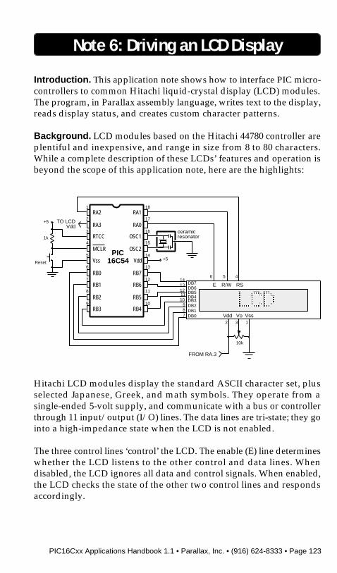
Introduction. This application note shows how to interface PIC micro-controllers to common Hitachi liquid-crystal display (LCD) modules.The program, in Parallax assembly language, writes text to the display,reads display status, and creates custom character patterns.
Background. LCD modules based on the Hitachi 44780 controller areplentiful and inexpensive, and range in size from 8 to 80 characters.While a complete description of these LCDs’ features and operation isbeyond the scope of this application note, here are the highlights:
Hitachi LCD modules display the standard ASCII character set, plusselected Japanese, Greek, and math symbols. They operate from asingle-ended 5-volt supply, and communicate with a bus or controllerthrough 11 input/output (I/O) lines. The data lines are tri-state; they gointo a high-impedance state when the LCD is not enabled.
The three control lines ‘control’ the LCD. The enable (E) line determineswhether the LCD listens to the other control and data lines. Whendisabled, the LCD ignores all data and control signals. When enabled,the LCD checks the state of the other two control lines and respondsaccordingly.
ceramicresonator
E RS
2
Vdd3
Vo1
R/W
Vss
PIC16C54
1
2
3
4
5
6
7
8
9
18
17
16
15
14
13
12
11
10
RA2
RA3
RTCC
MCLR
Vss
RB0
RB1
RB2
RB3
RA1
RA0
OSC1
OSC2
Vdd
RB7
RB6
RB5
RB4
+5
1k
Reset+5
FROM RA.3
TO LCDVdd
6 5 4
DB7DB6DB5DB4DB3DB2DB1DB0
10k
1413121110
987
Page 124 • PIC16Cxx Applications Handbook 1.1 • Parallax, Inc. • (916) 624-8333
The read/write (R/W) line determines whether the LCD reads bitsfrom the data lines, or writes bits to them.
Register-select (RS) determines whether the LCD treats data as instruc-tions or characters. Here is the truth table for the control lines:
E 0 LCD disabled.1 LCD enabled.
R/W 0 Write to LCD.1 Read from LCD.
RS 0 Instructions.1 Characters/bytes.
Writing to the LCD requires the basic steps listed below. (Reading fromthe LCD follows the same sequence, but the R/W bit must be set.)
• Clear the R/W bit.• Set or clear the RS bit as appropriate.• Set the E bit (E=1).• Clear the E bit (E=0).
When power is applied to the LCD, it resets itself and waits forinstructions. Typically these instructions turn on the display, turn onthe cursor, and set the display to print from left to right.
Once the LCD is initialized, it can receive data or instructions. If itreceives a character, it prints it on the screen and moves the cursor onecharacter to the right. The cursor marks the next location at which acharacter will be printed. The LCD’s internal processing is similar. Amemory pointer determines where the next byte will be stored. Whena new byte arrives, the pointer advances. To write to sequential loca-tions, establish the starting address and then write one byte afteranother.
Characters are stored in data display (DD) RAM. Regardless of thenumber of characters visible on the display, the LCD has 80 bytes of DDRAM. Characters in off-screen RAM can be made visible by scrollingthe display.
The LCD also has 64 bytes of character-generator (CG) RAM. Data in
Note 6: Driving an LCD Display
PIC16Cxx Applications Handbook 1.1 • Parallax, Inc. • (916) 624-8333 • Page 125
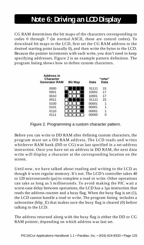
CG RAM determines the bit maps of the characters corresponding tocodes 0 through 7 (in normal ASCII, these are control codes). Todownload bit maps to the LCD, first set the CG RAM address to thedesired starting point (usually 0), and then write the bytes to the LCD.Because the pointer increments with each write, you don’t need to keepspecifying addresses. Figure 2 is an example pattern definition. Theprogram listing shows how to define custom characters.
Before you can write to DD RAM after defining custom characters, theprogram must set a DD RAM address. The LCD reads and writeswhichever RAM bank (DD or CG) was last specified in a set-addressinstruction. Once you have set an address in DD RAM, the next datawrite will display a character at the corresponding location on thescreen.
Until now, we have talked about reading and writing to the LCD asthough it were regular memory. It’s not. The LCD’s controller takes 40to 120 microseconds (µs) to complete a read or write. Other operationscan take as long as 5 milliseconds. To avoid making the PIC wait aworst-case delay between operations, the LCD has a 1µs instruction thatreads the address counter and a busy flag. When the busy flag is set (1),the LCD cannot handle a read or write. The program listing includes asubroutine (blip_E) that makes sure the busy flag is cleared (0) beforetalking to the LCD.
The address returned along with the busy flag is either the DD or CGRAM pointer, depending on which address was last set.
Note 6: Driving an LCD Display
Address inCharacter
Generator RAM Bit Map Data
00000001001000110100010101100111
0111110001100010111100001000010000100000
“retw”Data
15171715
1110
Figure 2. Programming a custom character pattern.

Page 126 • PIC16Cxx Applications Handbook 1.1 • Parallax, Inc. • (916) 624-8333
Note 6: Driving an LCD Display
Figure 3 is a list of LCD instructions for reading and writing memory.Some other useful instructions appear as constants in the beginning ofthe program listing.
How it works. The circuit in figure 1 interfaces a PIC to an LCD module.When the power is turned on, or the circuit is reset, the PIC initializesthe LCD, downloads four custom characters, and prints “Parallax”forward and backward (with custom mirrored characters).
The potentiomenter connected to the LCD’s Vo pin controls contrast. Ifthe display is hard to read, appears blank, or is filled with black pixels,adjust this control.
Power to the LCD is controlled by a PIC I/O bit. In this way, the PICensures that the 5-volt supply is up and stable before switching on theLCD. If the circuit used the PIC’s sleep mode, it could shut down theLCD to save approximately 1.5 mA. If you use this feature, make surethat the data and control lines are cleared to 0’s or set to input beforeputting the PIC to sleep. Otherwise, leakage through the LCD’s protec-tion diodes might continue to power it.
Set DD RAM addressRS R/W DB7 DB6 DB5 DB4 DB3 DB2 DB1 DB0
0 0 1 A A A A A A A
Set CG RAM addressRS R/W DB7 DB6 DB5 DB4 DB3 DB2 DB1 DB0
0 0 0 1 A A A A A A
Read busy flag and addressRS R/W DB7 DB6 DB5 DB4 DB3 DB2 DB1 DB0
0 1 Bsy A A A A A A A
Write data to RAM (CG or DD, most recently set)RS R/W DB7 DB6 DB5 DB4 DB3 DB2 DB1 DB0
1 0 D D D D D D D D
Read data from RAM (CG or DD, most recently set)RS R/W DB7 DB6 DB5 DB4 DB3 DB2 DB1 DB0
1 1 D D D D D D D D
Figure 3. Commonly used memory operations.(A = address; D = data; Bsy = busy)
PIC16Cxx Applications Handbook 1.1 • Parallax, Inc. • (916) 624-8333 • Page 127
Note 6: Driving an LCD Display
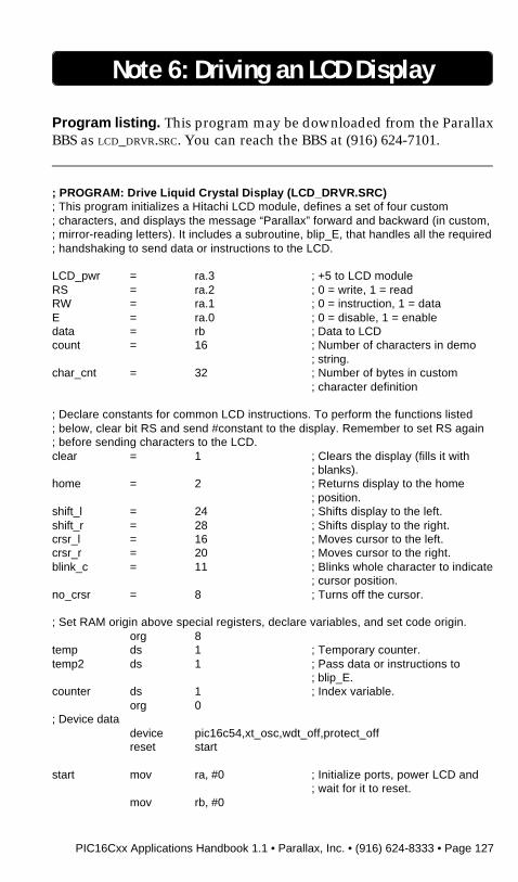
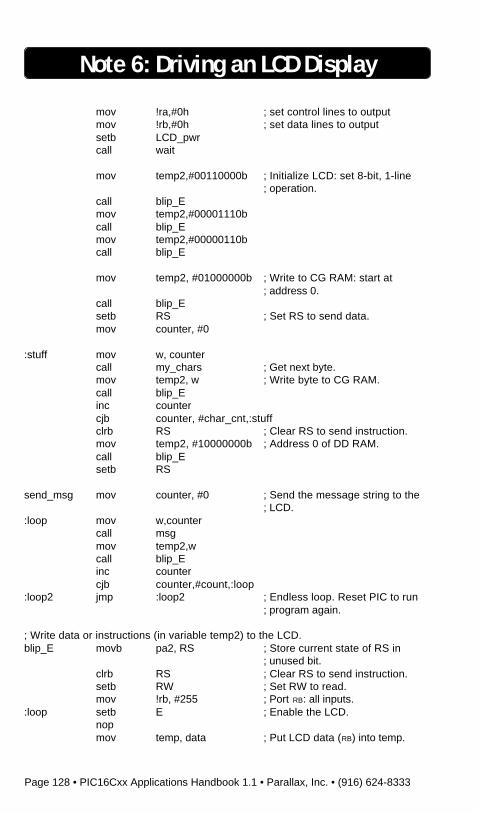
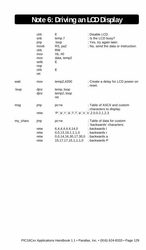
Program listing. This program may be downloaded from the ParallaxBBS as LCD_DRVR.SRC. You can reach the BBS at (916) 624-7101.
; PROGRAM: Drive Liquid Crystal Display (LCD_DRVR.SRC); This program initializes a Hitachi LCD module, defines a set of four custom; characters, and displays the message “Parallax” forward and backward (in custom,; mirror-reading letters). It includes a subroutine, blip_E, that handles all the required; handshaking to send data or instructions to the LCD.
LCD_pwr = ra.3 ; +5 to LCD moduleRS = ra.2 ; 0 = write, 1 = readRW = ra.1 ; 0 = instruction, 1 = dataE = ra.0 ; 0 = disable, 1 = enabledata = rb ; Data to LCDcount = 16 ; Number of characters in demo
; string.char_cnt = 32 ; Number of bytes in custom
; character definition
; Declare constants for common LCD instructions. To perform the functions listed; below, clear bit RS and send #constant to the display. Remember to set RS again; before sending characters to the LCD.clear = 1 ; Clears the display (fills it with
; blanks).home = 2 ; Returns display to the home
; position.shift_l = 24 ; Shifts display to the left.shift_r = 28 ; Shifts display to the right.crsr_l = 16 ; Moves cursor to the left.crsr_r = 20 ; Moves cursor to the right.blink_c = 11 ; Blinks whole character to indicate
; cursor position.no_crsr = 8 ; Turns off the cursor.
; Set RAM origin above special registers, declare variables, and set code origin.org 8
temp ds 1 ; Temporary counter.temp2 ds 1 ; Pass data or instructions to
; blip_E.counter ds 1 ; Index variable.
org 0; Device data
device pic16c54,xt_osc,wdt_off,protect_offreset start
start mov ra, #0 ; Initialize ports, power LCD and; wait for it to reset.
mov rb, #0
Page 128 • PIC16Cxx Applications Handbook 1.1 • Parallax, Inc. • (916) 624-8333
mov !ra,#0h ; set control lines to outputmov !rb,#0h ; set data lines to outputsetb LCD_pwrcall wait
mov temp2,#00110000b ; Initialize LCD: set 8-bit, 1-line; operation.
call blip_Emov temp2,#00001110bcall blip_Emov temp2,#00000110bcall blip_E
mov temp2, #01000000b ; Write to CG RAM: start at; address 0.
call blip_Esetb RS ; Set RS to send data.mov counter, #0
:stuff mov w, countercall my_chars ; Get next byte.mov temp2, w ; Write byte to CG RAM.call blip_Einc countercjb counter, #char_cnt,:stuffclrb RS ; Clear RS to send instruction.mov temp2, #10000000b ; Address 0 of DD RAM.call blip_Esetb RS
send_msg mov counter, #0 ; Send the message string to the; LCD.
:loop mov w,countercall msgmov temp2,wcall blip_Einc countercjb counter,#count,:loop
:loop2 jmp :loop2 ; Endless loop. Reset PIC to run; program again.
; Write data or instructions (in variable temp2) to the LCD.blip_E movb pa2, RS ; Store current state of RS in
; unused bit.clrb RS ; Clear RS to send instruction.setb RW ; Set RW to read.mov !rb, #255 ; Port RB: all inputs.
:loop setb E ; Enable the LCD.nopmov temp, data ; Put LCD data (RB) into temp.
Note 6: Driving an LCD Display
PIC16Cxx Applications Handbook 1.1 • Parallax, Inc. • (916) 624-8333 • Page 129
clrb E ; Disable LCD.snb temp.7 ; Is the LCD busy?jmp :loop ; Yes, try again later.movb RS, pa2 ; No, send the data or instruction.clrb RWmov !rb, #0mov data, temp2setb Enopclrb Eret
wait mov temp2,#200 ; Create a delay for LCD power-on; reset.
:loop djnz temp,:loopdjnz temp2,:loop
ret
msg jmp pc+w ; Table of ASCII and custom; characters to display.
retw ‘P’,’a’,’r’,’a’,’l’,’l’,’a’,’x’,’x’,2,0,0,2,1,2,3
my_chars jmp pc+w ; Table of data for custom; ‘backwards’ characters.
retw 6,4,4,4,4,4,14,0 ; backwards lretw 0,0,13,19,1,1,1,0 ; backwards rretw 0,0,14,16,30,17,30,0 ; backwards aretw 15,17,17,15,1,1,1,0 ; backwards P
Note 6: Driving an LCD Display

Page 130 • PIC16Cxx Applications Handbook 1.1 • Parallax, Inc. • (916) 624-8333
BLANK PAGE
PIC16Cxx Applications Handbook 1.1 • Parallax, Inc. • (916) 624-8333 • Page 131
Note 7: Direct & Indirect Addressing
Introduction. This application note describes direct and indirect ad-dressing and shows a method for avoiding the gaps in the PIC16C57’sbanked memory.
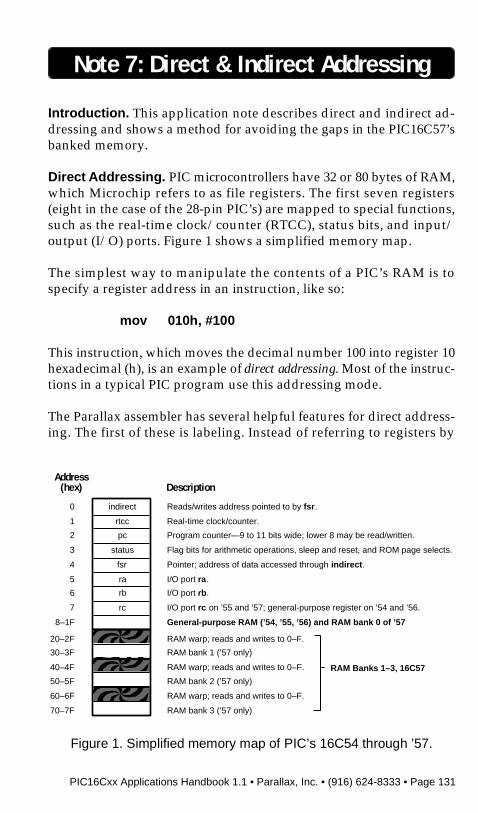
Direct Addressing. PIC microcontrollers have 32 or 80 bytes of RAM,which Microchip refers to as file registers. The first seven registers(eight in the case of the 28-pin PIC’s) are mapped to special functions,such as the real-time clock/counter (RTCC), status bits, and input/output (I/O) ports. Figure 1 shows a simplified memory map.
The simplest way to manipulate the contents of a PIC’s RAM is tospecify a register address in an instruction, like so:
mov 010h, #100
This instruction, which moves the decimal number 100 into register 10hexadecimal (h), is an example of direct addressing. Most of the instruc-tions in a typical PIC program use this addressing mode.
The Parallax assembler has several helpful features for direct address-ing. The first of these is labeling. Instead of referring to registers by
Figure 1. Simplified memory map of PIC’s 16C54 through ’57.
Address(hex) Description
8–1F General-purpose RAM (’54, ’55, ’56) and RAM bank 0 of ’57
indirect Reads/writes address pointed to by fsr.0
rtcc Real-time clock/counter.1
pc Program counter—9 to 11 bits wide; lower 8 may be read/written.2
status Flag bits for arithmetic operations, sleep and reset, and ROM page selects.3
fsr Pointer; address of data accessed through indirect.4
ra I/O port ra.5
rb I/O port rb.6
rc I/O port rc on ’55 and ’57; general-purpose register on ’54 and ’56.7
RAM Banks 1–3, 16C57
RAM warp; reads and writes to 0–F.20–2F
RAM bank 1 (’57 only)30–3F
RAM warp; reads and writes to 0–F.40–4F
RAM bank 2 (’57 only)50–5F
RAM warp; reads and writes to 0–F.60–6F
RAM bank 3 (’57 only)70–7F
Page 132 • PIC16Cxx Applications Handbook 1.1 • Parallax, Inc. • (916) 624-8333
address, you may assign names to them:
counter = 010h ;Program header...mov counter, #100
Labeled memory locations are often called variables. They make aprogram more understandable and easier to modify. Suppose youneeded to change the location in which the counter data was stored.Without the label, you would have to rely on your text editor’s search-and-replace function (which might also change other numbers contain-ing “10”). With a label, you could change the counter = ... value in theprogram header only.
You can also define variables without specifying their address by usingthe ds (define space) directive:
org 8 ;Start above special registers.counter ds 1 ;One byte labeled “counter.”
.
.
.mov counter, #100
Using ds assigns the label to the next available register. This ensuresthat no two labels apply to the same register, making variable assign-ments more portable from one program to another. The only caution inusing ds is that you must set the origin using the org directive twice; oncefor the starting point of variables in RAM, and again (usually at 0) forthe starting point of your program in ROM.
Labels can be assigned to individual bits in two ways. First, if the bitbelongs to a labeled byte, add .x to the label, where x is the bit number(0–7). Or assign the bit its own label:
LED = ra.3 ;Bit 3 of port ra controls LED.
The Parallax assembler has predefined labels for the special-purpose
Note 7: Direct & Indirect Addressing

PIC16Cxx Applications Handbook 1.1 • Parallax, Inc. • (916) 624-8333 • Page 133
registers, and the bits of the status register. See your manual for a list.
Indirect Addressing. The registers used in direct addressing are setforever when the program is burned into the PIC’s ROM. They cannotchange. However, many powerful programming techniques are basedon computing storage locations. Consider a keyboard buffer. If key-strokes can’t be processed immediately, they are stored in sequentialbytes of memory. Pointers—variables containing addresses of othervariables—track the locations of data entered and data processed.
The PIC’s indirect addressing mode allows the use of pointers and thehigh-level data structures that go with them, such as stacks and queues.Using indirect addressing for the earlier example (writing 100 toregister 10h) would look like this:
mov fsr, #010h ;Set pointer to 10h.mov indirect, #100 ;Store 100 to indirect.
The value in the file select register (fsr; register 04h) is used as theaddress in any instruction that reads/writes indirect (register 00h). Sostoring 10h in the fsr and then writing 100 to indirect is the same aswriting 100 to address 10h.
Note 7: Direct & Indirect Addressing
7 6 5 4 3 2 1 0
address, 0–Fh
banked memory enable;1 = on, 0 = off
bank select, 0–3h
unused; reads as 1
MemoryRegister
banks:
0 10h to 1Fh
1 30h to 3Fh
2 50h to 5Fh
3 70h to 7Fh
Figure 2. The 16C57file-select register.

Page 134 • PIC16Cxx Applications Handbook 1.1 • Parallax, Inc. • (916) 624-8333
A more practical example would be to store a series of values from anI/O port to sequential registers in memory. All it takes is a loop like this:
mov pointer, #010h ;Set start address.:loop mov fsr, pointer ;Put pointer into fsr.
mov indirect, rb ;Move rb to indirect.inc pointer ;pointer = pointer + 1.cjb pointer,#01Fh,:loop
This fragment assumes that a variable named pointer was declaredpreviously (using =, equ, or ds), and that rb is set for input. The loop willrapidly fill registers 10h through 1Fh with data samples from rb.
PIC’s with 32 bytes of RAM (’54, ’55, and ’56) have a five-bit-wide fsr.Since all registers are eight bits wide, the highest three bits of the fsr inthese devices are fixed, and always read as 1’s. Keep this in mind if youplan to perform comparisons (such as the last line of the example above)directly on the fsr. It will always read 224 (11100000b) higher than theactual address it points to.
The 16C57 has 80 bytes of RAM and a seven-bit-wide fsr. The highest bitof its fsr is fixed and reads as a 1. Seven bits allows for 128 addresses, butonly 80 are used. The remaining 48 addresses are accounted for by three16-byte gaps in the 57’s memory map. See the RAM warps in figure 1.
Because these warps map to the lowest file registers of the PIC, they cancause real trouble by altering data in the special-purpose registers. Toavoid this problem, consider using a subroutine to straighten out thememory map and avoid the warps. Below is an excerpt from a programthat uses the registers from 10h on up as a storage buffer for up to 64characters of ASCII text. For the purposes of the program, address10his location 0 in the buffer; 7F is location 63.
When the program needs to write a value representing a position in thebuffer to the fsr, it puts the value into the w register and calls buf_ptr(buffer pointer).
Note 7: Direct & Indirect Addressing

PIC16Cxx Applications Handbook 1.1 • Parallax, Inc. • (916) 624-8333 • Page 135
buf_ptr mov temp,wmov fsr, tempcjae temp,#030h,:bank3cjae temp,#020h,:bank2cjae temp,#010h,:bank1jmp :bank0
:bank3 add fsr,#010h:bank2 add fsr,#010h:bank1 add fsr,#010h:bank0 add fsr,#010h
ret
It may be more useful in some applications to treat these memorylocations as register banks, as they are described in the Microchipliterature. According to this model, bit 4 of the fsr enables bank selectionwhen it is a 1. The 16-byte bank in use is then selected by bits 5 and 6 ofthe fsr as shown in figure 2.
This model explains the warps in the memory map. Each of the threewarp addresses (20h, 40h, and 60h) has a 0 in the bit-4 position. Thisdisables banked memory, causing the PIC to disregard all but bits 0through 3 of the address.
Note 7: Direct & Indirect Addressing

Page 136 • PIC16Cxx Applications Handbook 1.1 • Parallax, Inc. • (916) 624-8333
BLANK PAGE

PIC16Cxx Applications Handbook 1.1 • Parallax, Inc. • (916) 624-8333 • Page 137
Note 8: The PIC16C71 A/D Converter
Introduction. This application note presents a program in Parallaxassembly language that uses the PIC16C71’s built-in analog-to-digitalconverter (ADC) to measure an input voltage and flash an LED at aproportional rate.
Background. One of the most popular enhancements offered by thenew PIC16C71 is its eight-bit ADC, which features:
• 20-microsecond (µs) conversion time (nearly 50,000 samples persecond, depending on additional processing time).
• Four multiplexed inputs.
• Built-in sample-and-hold.
• ±1 least-significant-bit accuracy (better than 20 millivolts with a5-volt reference).
• Selectable voltage reference (Vdd or RA.3).
While using the ADC is fairly straightforward, it does require a seriesof decisions much like those required to select and use a separate ADC.The first consideration is hardware.
Input Characteristics. The ADC produces a digital output that is propor-tional to an analog input. A voltage reference determines the inputvoltage that will produce a full-scale (255) digital output. The voltage
10k
4.7 pF
PIC16C71
1
2
3
4
5
6
7
8
9
18
17
16
15
14
13
12
11
10
RTCC/RA4
MCLR
Vss
RB0
RB1
RB2
RB3
RA0/Ain0
OSC1
OSC2
Vdd
RB7
RB6
RB5
RB4
+5
+5
5k potRA1/Ain1RA2/Ain2
RA3/Ain3
220
LED
1k

Page 138 • PIC16Cxx Applications Handbook 1.1 • Parallax, Inc. • (916) 624-8333
reference can be the +5-volt power-supply rail, or some other voltagesource between 3 volts and the power supply voltage + 0.3 volts. TheADC is most accurate with a reference voltage of 5.12 volts, accordingto the manufacturer’s specifications.
The specifications recommend that the analog voltage source beingmeasured have an impedance of no more than 10kΩ. Above this value,accuracy suffers. They also suggest that the source have not less than500Ω impedance. This limits current through the PIC in the event thatyour program reconfigures the analog input pin as an output, or someother circuit trauma occurs.
Clock Source. The PIC’s ADC, like the PIC itself, requires a clock signal.The ADC performs a conversion in 10 of its clock cycles, which must beno shorter than 2µs. Clock signals for the ADC can come from twosources, the PIC’s own clock or an on-chip resistor-capacitor (RC)oscillator exclusive to the ADC.
When the PIC’s clock is the source, it is divided by 2, 8 or 32, dependingon the status of the ADC clock source bits (see figure 2). In order to havean ADC clock signal of 2µs or longer, the PIC clock speed must notexceed 1, 4, or 16 MHz, respectively. If you plan to run the PIC fasterthan 16 MHz, or you want the ADC conversion rate to be independentof the PIC clock, you must use the ADC’s RC oscillator.
The tradeoff in using the RC oscillator is that its period can vary from2 to 6µs, depending on temperature and manufacturing tolerances.
Interrupt Enable. The ADC is relatively slow—at 20 MHz the PIC canexecute 100 instructions in the 20µs the ADC takes to make a conver-sion. In some cases, it makes sense not to force a PIC program to wait ina loop for a conversion to finish. The alternative is to configure the ADCto announce “conversion complete” through an interrupt. To keepthings as simple as possible, the example program does not takeadvantage of interrupt capability.
Pin Configuration and Voltage Reference. Pins RA.0 through RA.3 can serveas inputs to the ADC. One of the choices you must make when settingup the ADC is which pins to configure as analog inputs, which (if any)as digital inputs, and what to use as a voltage reference. Figure 2 shows
Note 8: The PIC16C71 A/D Converter
PIC16Cxx Applications Handbook 1.1 • Parallax, Inc. • (916) 624-8333 • Page 139
the range of available choices.
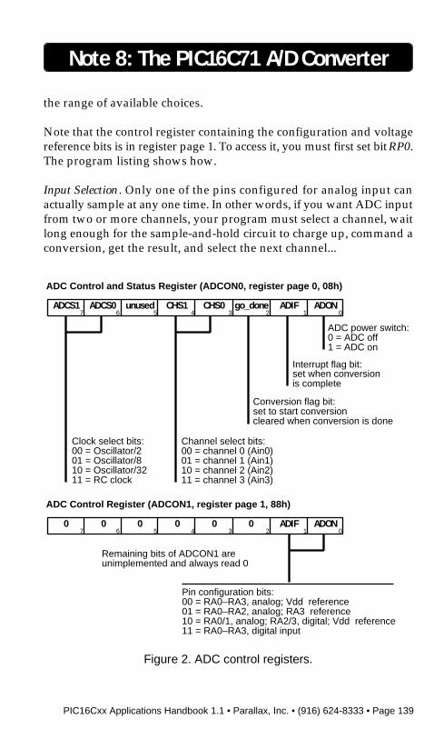
Note that the control register containing the configuration and voltagereference bits is in register page 1. To access it, you must first set bit RP0.The program listing shows how.
Input Selection. Only one of the pins configured for analog input canactually sample at any one time. In other words, if you want ADC inputfrom two or more channels, your program must select a channel, waitlong enough for the sample-and-hold circuit to charge up, command aconversion, get the result, and select the next channel...
Note 8: The PIC16C71 A/D Converter
Figure 2. ADC control registers.
ADC Control and Status Register (ADCON0, register page 0, 08h)
CHS0 go_done ADIF ADONCHS1unusedADCS0ADCS10234567
ADC power switch:0 = ADC off1 = ADC on
Interrupt flag bit:set when conversionis complete
Conversion flag bit:set to start conversioncleared when conversion is done
Channel select bits:00 = channel 0 (Ain0)01 = channel 1 (Ain1)10 = channel 2 (Ain2)11 = channel 3 (Ain3)
1
Clock select bits:00 = Oscillator/201 = Oscillator/810 = Oscillator/3211 = RC clock
Pin configuration bits:00 = RA0–RA3, analog; Vdd reference01 = RA0–RA2, analog; RA3 reference10 = RA0/1, analog; RA2/3, digital; Vdd reference11 = RA0–RA3, digital input
Remaining bits of ADCON1 areunimplemented and always read 0
ADC Control Register (ADCON1, register page 1, 88h)
0 0 ADIF ADON00000234567 1

Page 140 • PIC16Cxx Applications Handbook 1.1 • Parallax, Inc. • (916) 624-8333
How long should the program wait for the sample-and-hold? Micro-chip suggests a worst case of 4.67µs plus two ADC clock cycles (after aconversion, the sample-and-hold takes a two-cycle break before itbegins sampling again).
How it works. The PIC in figure 1 accepts a voltage from a pot wired asvariable voltage divider. The PIC’s ADC, which is set up to use Vdd asa reference, outputs a one-byte value that’s proportional to the inputvoltage. This value controls a timing routine that flashes an LED. Whenthe input voltage is near 5 volts, the LED flashes about once a second.When it’s near 0, the LED flashes very rapidly.
The program listing shows how it’s done. Most of the code is devotedto setting up the ADC. Constants at the beginning of the program areassigned with values that, when loaded into the appropriate ADCcontrol registers, turn the ADC’s various features on and off. If you wishto change, for instance, the pin that the circuit uses for analog input, justcomment out the line containing AD_ch = 0 and uncomment the desiredchannel (“commenting” and “uncommenting” are handy techniquesfor temporarily removing and restoring instructions in source code.Putting a semicolon (;) in front of a line causes the assembler to ignoreit, as though it were a comment).
If you accidentally leave two assignements for AD_ch uncommented,the assembler will catch the mistake, flag the “redefinition” and tell youthe line number of the error.
The assembler combines values assigned to ADC_ch and ADC_clk intoa single byte by performing a logical OR (|) on the values and puttingthe result into another constant, ADC_ctl. This technique makes theprogram easier to understand and modify, and doesn’t cost a thing inPIC program memory or processing time. The assembler does all thework.
Program listing. This program may be downloaded from the ParallaxBBS as ADC71.SRC. You can reach the BBS at (916) 624-7101.
Note 8: The PIC16C71 A/D Converter
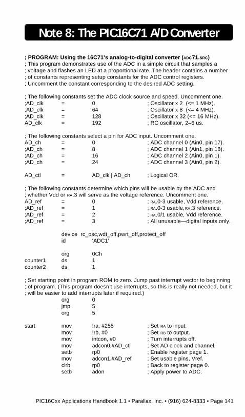
PIC16Cxx Applications Handbook 1.1 • Parallax, Inc. • (916) 624-8333 • Page 141
Note 8: The PIC16C71 A/D Converter
; PROGRAM: Using the 16C71’s analog-to-digital converter (ADC71.SRC); This program demonstrates use of the ADC in a simple circuit that samples a; voltage and flashes an LED at a proportional rate. The header contains a number; of constants representing setup constants for the ADC control registers.; Uncomment the constant corresponding to the desired ADC setting.
; The following constants set the ADC clock source and speed. Uncomment one.;AD_clk = 0 ; Oscillator x 2 (<= 1 MHz).;AD_clk = 64 ; Oscillator x 8 (<= 4 MHz).;AD_clk = 128 ; Oscillator x 32 (<= 16 MHz).AD_clk = 192 ; RC oscillator, 2–6 us.
; The following constants select a pin for ADC input. Uncomment one.AD_ch = 0 ; ADC channel 0 (Ain0, pin 17).;AD_ch = 8 ; ADC channel 1 (Ain1, pin 18).;AD_ch = 16 ; ADC channel 2 (Ain0, pin 1).;AD_ch = 24 ; ADC channel 3 (Ain0, pin 2).
AD_ctl = AD_clk | AD_ch ; Logical OR.
; The following constants determine which pins will be usable by the ADC and; whether Vdd or RA.3 will serve as the voltage reference. Uncomment one.AD_ref = 0 ; RA.0-3 usable, Vdd reference.;AD_ref = 1 ; RA.0-3 usable, RA.3 reference.;AD_ref = 2 ; RA.0/1 usable, Vdd reference.;AD_ref = 3 ; All unusable—digital inputs only.
device rc_osc,wdt_off,pwrt_off,protect_offid ‘ADC1’
org 0Chcounter1 ds 1counter2 ds 1
; Set starting point in program ROM to zero. Jump past interrupt vector to beginning; of program. (This program doesn’t use interrupts, so this is really not needed, but it; will be easier to add interrupts later if required.)
org 0jmp 5org 5
start mov !ra, #255 ; Set RA to input.mov !rb, #0 ; Set RB to output.mov intcon, #0 ; Turn interrupts off.mov adcon0,#AD_ctl ; Set AD clock and channel.setb rp0 ; Enable register page 1.mov adcon1,#AD_ref ; Set usable pins, Vref.clrb rp0 ; Back to register page 0.setb adon ; Apply power to ADC.

Page 142 • PIC16Cxx Applications Handbook 1.1 • Parallax, Inc. • (916) 624-8333
Note 8: The PIC16C71 A/D Converter
:loop call wait ; Delay for time determined by; ADC input.
setb rb.0 ; Turn LED on.call wait ; Delay for time determined by
; ADC input.clrb rb.0 ; Turn LED off.goto :loop ; Endless loop.
wait setb go_done ; Start conversion.:not_done snb go_done ; Poll for 0 (done).
jmp :not_done ; If 1, poll again.mov counter2,adres ; Move ADC result into counter.
; The number of loops this delay routine makes is dependent on the result of the AD; conversion. The higher the voltage, the longer the delay.:loop djnz counter1, :loop
djnz counter2, :loopret

PIC16Cxx Applications Handbook 1.1 • Parallax, Inc. • (916) 624-8333 • Page 143
BLANK PAGE

Page 144 • PIC16Cxx Applications Handbook 1.1 • Parallax, Inc. • (916) 624-8333
BLANK PAGE
PIC16Cxx Applications Handbook 1.1 • Parallax, Inc. • (916) 624-8333 • Page 145
Note 9: Managing Multiple Tasks
Introduction. This application note presents a program in Parallaxassembly language that demonstrates a technique for organizing aprogram into multiple tasks.
Background. Like most computers, the PIC executes its instructionsone at a time. People tend to write programs that work the same way;they perform one task at a time.
It’s often useful to have the controller do more than one thing at a time,or at least seem to. The first step in this direction is often to exploit thedead time from one task—the time it would normally spend in a delayloop, for instance—to handle a second task. The PIC’s speed makes thisquite practical in many cases.
When several tasks must be handled at once, this approach can quicklybecome unworkable. What we need is a framework around which toorganize the tasks. We need an operating system.
The program in the listing illustrates an extremely simple operatingsystem that runs each of eight small subprograms in turn. When thesubprograms finish their work, they jump back to the system. Noticethat this method does not require the call instruction, so it leaves thetwo-level stack free for the use of the subprograms.
How it works. The circuit and program comprise an eight-LED flasher.Each of the LED’s flashes at a different rate. While this could beaccomplished differently, the program is easier to understand andmaintain because the code that controls each LED is a separate task.
The “system” portion of the program acts like a spinning rotary switch.Each time it executes, it increments the task number and switches to thenext task. It does this by taking advantage of the PIC’s ability to modifythe program counter. Once the task number is loaded into the workingregister, the program executes the instruction jmp pc+w. The destina-tions of these jumps contain jmp instructions themselves, and send theprogram to one of the eight tasks. Not surprisingly, a list of jmpinstructions arranged like this is called a “jump table.”
Modifications. For the sake of simplicity, this task-switching programlacks one important attribute: fixed timing. The individual tasks are
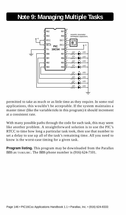
Page 146 • PIC16Cxx Applications Handbook 1.1 • Parallax, Inc. • (916) 624-8333
permitted to take as much or as little time as they require. In some realapplications, this wouldn’t be acceptable. If the system maintains amaster timer (like the variable ticks in this program) it should incrementat a consistent rate.
With many possible paths through the code for each task, this may seemlike another problem. A straightforward solution is to use the PIC’sRTCC to time how long a particular task took, then use that number toset a delay to use up all of the task’s remaining time. All you need toknow is the worst-case timing for a given task.
Program listing. This program may be downloaded from the ParallaxBBS as TASKS.SRC. The BBS phone number is (916) 624-7101.
Note 9: Managing Multiple Tasks
LED470
LED470
LED470
PIC16C54
1
2
3
4
5
6
7
8
9
18
17
16
15
14
13
12
11
10
RA2
RA3
RTCC
MCLR
Vss
RB0
RB1
RB2
RB3
RA1
RA0
OSC1
OSC2
Vdd
RB7
RB6
RB5
RB4
+5
+5
LED470
LED470
LED470
LED470
LED470
ceramic resonatorw/integral capacitors
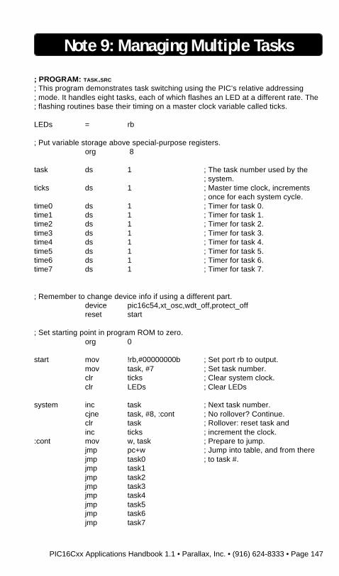
PIC16Cxx Applications Handbook 1.1 • Parallax, Inc. • (916) 624-8333 • Page 147
Note 9: Managing Multiple Tasks
; PROGRAM: TASK.SRC
; This program demonstrates task switching using the PIC’s relative addressing; mode. It handles eight tasks, each of which flashes an LED at a different rate. The; flashing routines base their timing on a master clock variable called ticks.
LEDs = rb
; Put variable storage above special-purpose registers.org 8
task ds 1 ; The task number used by the; system.
ticks ds 1 ; Master time clock, increments; once for each system cycle.
time0 ds 1 ; Timer for task 0.time1 ds 1 ; Timer for task 1.time2 ds 1 ; Timer for task 2.time3 ds 1 ; Timer for task 3.time4 ds 1 ; Timer for task 4.time5 ds 1 ; Timer for task 5.time6 ds 1 ; Timer for task 6.time7 ds 1 ; Timer for task 7.
; Remember to change device info if using a different part.device pic16c54,xt_osc,wdt_off,protect_offreset start
; Set starting point in program ROM to zero.org 0
start mov !rb,#00000000b ; Set port rb to output.mov task, #7 ; Set task number.clr ticks ; Clear system clock.clr LEDs ; Clear LEDs
system inc task ; Next task number.cjne task, #8, :cont ; No rollover? Continue.clr task ; Rollover: reset task andinc ticks ; increment the clock.
:cont mov w, task ; Prepare to jump.jmp pc+w ; Jump into table, and from therejmp task0 ; to task #.jmp task1jmp task2jmp task3jmp task4jmp task5jmp task6jmp task7
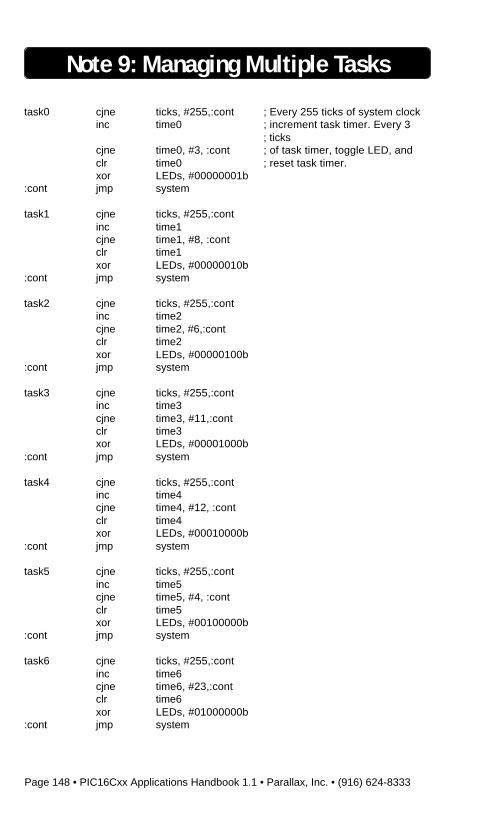
Page 148 • PIC16Cxx Applications Handbook 1.1 • Parallax, Inc. • (916) 624-8333
Note 9: Managing Multiple Tasks
task0 cjne ticks, #255,:cont ; Every 255 ticks of system clockinc time0 ; increment task timer. Every 3
; tickscjne time0, #3, :cont ; of task timer, toggle LED, andclr time0 ; reset task timer.xor LEDs, #00000001b
:cont jmp system
task1 cjne ticks, #255,:continc time1cjne time1, #8, :contclr time1xor LEDs, #00000010b
:cont jmp system
task2 cjne ticks, #255,:continc time2cjne time2, #6,:contclr time2xor LEDs, #00000100b
:cont jmp system
task3 cjne ticks, #255,:continc time3cjne time3, #11,:contclr time3xor LEDs, #00001000b
:cont jmp system
task4 cjne ticks, #255,:continc time4cjne time4, #12, :contclr time4xor LEDs, #00010000b
:cont jmp system
task5 cjne ticks, #255,:continc time5cjne time5, #4, :contclr time5xor LEDs, #00100000b
:cont jmp system
task6 cjne ticks, #255,:continc time6cjne time6, #23,:contclr time6xor LEDs, #01000000b
:cont jmp system
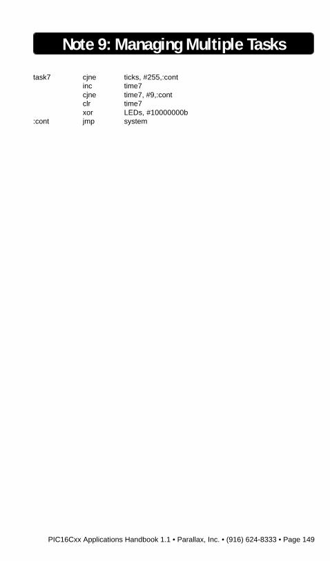
PIC16Cxx Applications Handbook 1.1 • Parallax, Inc. • (916) 624-8333 • Page 149
task7 cjne ticks, #255,:continc time7cjne time7, #9,:contclr time7xor LEDs, #10000000b
:cont jmp system
Note 9: Managing Multiple Tasks

Page 150 • PIC16Cxx Applications Handbook 1.1 • Parallax, Inc. • (916) 624-8333
BLANK PAGE

PIC16Cxx Applications Handbook 1.1 • Parallax, Inc. • (916) 624-8333 • Page 151
Note 10: An External A/D Converter
Introduction. This application note shows how to interface an 8-bitserial analog-to-digital converter to 16C5x-series PICs.
Background. Although the PIC 16C71 offers a built-in analog-to-digital converter (ADC), some users may prefer an external device. Onethat’s particularly suited to use with the PIC is the National Semicon-ductor ADC0831, available from Digi-Key, among others.
Interfacing the 831 requires only three input/output lines, and of these,two can be multiplexed with other functions (or additional 831s). Onlythe chip-select (CS) pin requires a dedicated line. The ADC’s range ofinput voltages is controlled by the VREF and VIN(–) pins. VREF sets thevoltage at which the ADC will return a full-scale output of 255, whileVIN(–) sets the voltage that will return 0.
In the example application, VIN(–) is at ground and VREF is at +5;however, these values can be as close together as 1 volt without harmingaccuracy or linearity. You may use diode voltage references or trim potsto set these values.
PIC16C54
1
2
3
4
5
6
7
8
9
18
17
16
15
14
13
12
11
10
RA2
RA3
RTCC
MCLR
Vss
RB0
RB1
RB2
RB3
RA1
RA0
OSC1
OSC2
Vdd
RB7
RB6
RB5
RB4
+5
+5
ceramic resonatorw/integral capacitors
ADC0831
1
2
3
4
8
7
6
5
CS
Vin(+)
Vin(–)
GND
Vcc
CLK
DO
Vref
0–5V in
LED
470
+5
+5
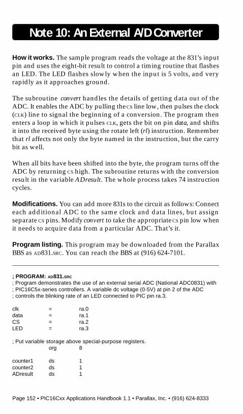
Page 152 • PIC16Cxx Applications Handbook 1.1 • Parallax, Inc. • (916) 624-8333
How it works. The sample program reads the voltage at the 831’s inputpin and uses the eight-bit result to control a timing routine that flashesan LED. The LED flashes slowly when the input is 5 volts, and veryrapidly as it approaches ground.
The subroutine convert handles the details of getting data out of theADC. It enables the ADC by pulling the CS line low, then pulses the clock(CLK) line to signal the beginning of a conversion. The program thenenters a loop in which it pulses CLK, gets the bit on pin data, and shiftsit into the received byte using the rotate left (rl) instruction. Rememberthat rl affects not only the byte named in the instruction, but the carrybit as well.
When all bits have been shifted into the byte, the program turns off theADC by returning CS high. The subroutine returns with the conversionresult in the variable ADresult. The whole process takes 74 instructioncycles.
Modifications. You can add more 831s to the circuit as follows: Connecteach additional ADC to the same clock and data lines, but assignseparate CS pins. Modify convert to take the appropriate CS pin low whenit needs to acquire data from a particular ADC. That’s it.
Program listing. This program may be downloaded from the ParallaxBBS as AD831.SRC. You can reach the BBS at (916) 624-7101.
Note 10: An External A/D Converter
; PROGRAM: AD831.SRC
; Program demonstrates the use of an external serial ADC (National ADC0831) with; PIC16C5x-series controllers. A variable dc voltage (0-5V) at pin 2 of the ADC; controls the blinking rate of an LED connected to PIC pin ra.3.
clk = ra.0data = ra.1CS = ra.2LED = ra.3
; Put variable storage above special-purpose registers.org 8
counter1 ds 1counter2 ds 1ADresult ds 1
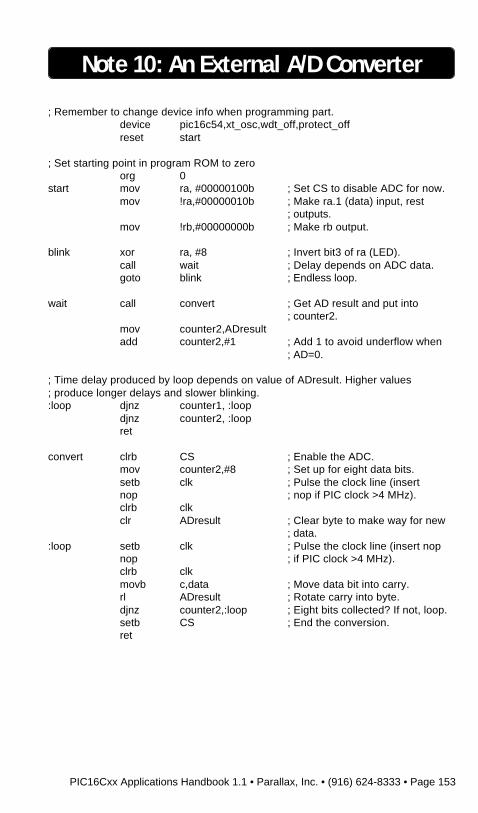
PIC16Cxx Applications Handbook 1.1 • Parallax, Inc. • (916) 624-8333 • Page 153
; Remember to change device info when programming part.device pic16c54,xt_osc,wdt_off,protect_offreset start
; Set starting point in program ROM to zeroorg 0
start mov ra, #00000100b ; Set CS to disable ADC for now.mov !ra,#00000010b ; Make ra.1 (data) input, rest
; outputs.mov !rb,#00000000b ; Make rb output.
blink xor ra, #8 ; Invert bit3 of ra (LED).call wait ; Delay depends on ADC data.goto blink ; Endless loop.
wait call convert ; Get AD result and put into; counter2.
mov counter2,ADresultadd counter2,#1 ; Add 1 to avoid underflow when
; AD=0.
; Time delay produced by loop depends on value of ADresult. Higher values; produce longer delays and slower blinking.:loop djnz counter1, :loop
djnz counter2, :loopret
convert clrb CS ; Enable the ADC.mov counter2,#8 ; Set up for eight data bits.setb clk ; Pulse the clock line (insertnop ; nop if PIC clock >4 MHz).clrb clkclr ADresult ; Clear byte to make way for new
; data.:loop setb clk ; Pulse the clock line (insert nop
nop ; if PIC clock >4 MHz).clrb clkmovb c,data ; Move data bit into carry.rl ADresult ; Rotate carry into byte.djnz counter2,:loop ; Eight bits collected? If not, loop.setb CS ; End the conversion.ret
Note 10: An External A/D Converter

Page 154 • PIC16Cxx Applications Handbook 1.1 • Parallax, Inc. • (916) 624-8333
BLANK PAGE

PIC16Cxx Applications Handbook 1.1 • Parallax, Inc. • (916) 624-8333 • Page 155
Note 11: Using Serial EEPROMs
Introduction. This application note shows how to use the Microchip93LC56 EEPROM to provide 256 bytes of nonvolatile storage. It pro-vides a tool kit of subroutines for reading, writing, and erasing theEEPROM. (Note that EEPROMs made by other manufacturers will notwork with the PIC16Cxx.)
Background. Many designs take advantage of the PIC’s ability to storetables of data in its EPROM program memory. The trouble is that thelarger the tables are, the smaller the space left for code. And manyapplications could benefit from the ability to occasionally update datatables for calibration or other purposes. What the PIC needs is theequivalent of a tiny disk drive.
The Microchip 93C56 and 93LC56 electrically erasable PROMs(EEPROMs) are perfect for these applications. They communicateserially via a three- or four-wire bus using a simple synchronous(clocked) communication protocol at rates of up to 2 million bits persecond (Mbps). It’s possible to read a byte in as little as 10 microseconds
LEDs470(all)
ceramic resonatorw/integral capacitors
PIC16C54
1
2
3
4
5
6
7
8
9
18
17
16
15
14
13
12
11
10
RA2
RA3
RTCC
MCLR
Vss
RB0
RB1
RB2
RB3
RA1
RA0
OSC1
OSC2
Vdd
RB7
RB6
RB5
RB4
+5
1k
93LC56
1
2
3
4
8
7
6
5
CS
CK
DI
DO
Vcc
NC
ORG
Vss
+5
+5
Page 156 • PIC16Cxx Applications Handbook 1.1 • Parallax, Inc. • (916) 624-8333
(including the time required to send the instruction opcode and ad-dress). Once a program has begun reading data from the EEPROM, itcan continue reading subsequent bytes without stopping. These areclocked in at the full 2 Mbps rate; 1 byte every 4 microseconds.
Erasing and writing these serial EEPROMs happens at a more leisurelypace. While the opcode, address, and data can be clocked into the chipat high speed, the EEPROM requires about 2 milliseconds to erase orwrite a byte. During this time, the chip cannot process additionalinstructions. The PIC can poll a flag to determine when the automaticerase/write programming cycle is over. As soon as this flag goes high,the EEPROM is ready for more instructions.
Data stored in the EEPROM will be retained for 10 years or more,according to the manufacturer. The factor that determines the EEPROM’slongevity in a particular application is the number of erase/writecycles. Depending on factors such as temperature and supply voltage,the EEPROM is good for 10,000 to 1 million erase/write cycles. Thisrules out its use as a substitute for ordinary RAM, since many PICapplications write to RAM thousands of times a second. At that rate, theEEPROM could be unusable in as little as 20 seconds! For a thoroughdiscussion of EEPROM endurance, see the Microchip Embedded Con-trol Handbook, publication number DS00092A, October 1992.
How it works. The circuit in the figure specifies a 93LC56 EEPROM, buta 93C56 will work as well. The difference is that the LC device has awider Vcc range (2.5–5.5 V, versus 4–5.5 V), lower current consumption(3 mA versus 4 mA), and can be somewhat slower in completinginternal erase/write operations, presumably at lower supply voltages.In general, the LC type is less expensive, and a better match for theoperating characteristics of the PIC.
The schematic shows the data in and data out (DI, DO) lines of theEEPROM connected together to a single PIC I/O pin. The 1k resistorprevents the PIC and DO from fighting over the bus during a readoperation. During a read, the PIC sends an opcode and an address to theEEPROM. As soon as it has received the address, the EEPROM activatesDO and puts a 0 on it. If the last bit of the address is a 1, the PIC couldend up sourcing current to ground through the EEPROM. The resistorlimits the current to a reasonable level.
Note 11: Using Serial EEPROMs
PIC16Cxx Applications Handbook 1.1 • Parallax, Inc. • (916) 624-8333 • Page 157
The program listing is a collection of subroutines for reading, writing,and erasing the EEPROM. All of these rely on Shout, a routine that shiftsbits out to the EEPROM. To perform an EEPROM operation, thesoftware loads the number of clock cycles into clocks and the data to beoutput into temp. It then calls Shout, which does the rest.
If you don’t have the EEPROM data handy (Microchip Data Book,DS00018D, 1991), you should know about a couple of subtleties. First,when the EEPROM powers up, it is write protected. You must callEEnable before trying to write or erase it. It’s a good idea to call EEdisbl(disable writes) as soon as possible after you’re done. Otherwise, apower glitch could alter the contents of your EEPROM. Also, youcannot write all locations (EEWrall) without first erasing all locations(EEwipe).
Modifications. The table of constants at the beginning of the listingspecifies the opcodes for each of the EEPROM operations. Although theopcodes are only three bits long, they are combined with a trailingdon’t-care bit. This bit is required for compatibility with the 512-byte93LC66. With the ’66, this would be address bit A8. If you want tomodify this code for the ’66, add a line to the read, write, and byte eraseroutines to copy A8 into bit 4 of temp just before calling Shout. If youwant to increase capacity by adding more EEPROMs, you can bus thedata and clock lines together and provide separate chip selects to eachdevice.
If you plan to run your PIC faster than 8 MHz, add one or two nopswhere marked in the listing. The clock must be high for at least 500nanoseconds. The low time must also be greater than 500 ns, but themove-data, rotate, and looping instructions provide enough delay.
Program listing. This program may be downloaded from the ParallaxBBS as EEPROM.SRC. You can reach the BBS at (916) 624-7101.
Note 11: Using Serial EEPROMs
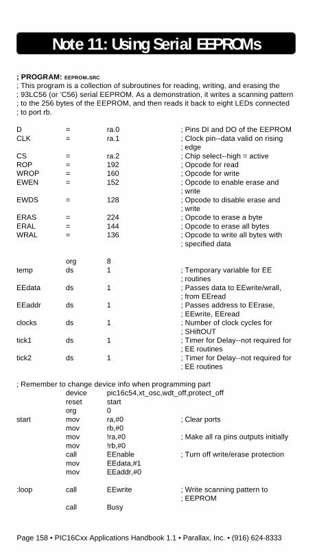
Page 158 • PIC16Cxx Applications Handbook 1.1 • Parallax, Inc. • (916) 624-8333
Note 11: Using Serial EEPROMs
; PROGRAM: EEPROM.SRC
; This program is a collection of subroutines for reading, writing, and erasing the; 93LC56 (or 'C56) serial EEPROM. As a demonstration, it writes a scanning pattern; to the 256 bytes of the EEPROM, and then reads it back to eight LEDs connected; to port rb.
D = ra.0 ; Pins DI and DO of the EEPROMCLK = ra.1 ; Clock pin--data valid on rising
; edgeCS = ra.2 ; Chip select--high = activeROP = 192 ; Opcode for readWROP = 160 ; Opcode for writeEWEN = 152 ; Opcode to enable erase and
; writeEWDS = 128 ; Opcode to disable erase and
; writeERAS = 224 ; Opcode to erase a byteERAL = 144 ; Opcode to erase all bytesWRAL = 136 ; Opcode to write all bytes with
; specified data
org 8temp ds 1 ; Temporary variable for EE
; routinesEEdata ds 1 ; Passes data to EEwrite/wrall,
; from EEreadEEaddr ds 1 ; Passes address to EErase,
; EEwrite, EEreadclocks ds 1 ; Number of clock cycles for
; SHiftOUTtick1 ds 1 ; Timer for Delay--not required for
; EE routinestick2 ds 1 ; Timer for Delay--not required for
; EE routines
; Remember to change device info when programming partdevice pic16c54,xt_osc,wdt_off,protect_offreset startorg 0
start mov ra,#0 ; Clear portsmov rb,#0mov !ra,#0 ; Make all ra pins outputs initiallymov !rb,#0call EEnable ; Turn off write/erase protectionmov EEdata,#1mov EEaddr,#0
:loop call EEwrite ; Write scanning pattern to; EEPROM
call Busy

PIC16Cxx Applications Handbook 1.1 • Parallax, Inc. • (916) 624-8333 • Page 159
Note 11: Using Serial EEPROMs
rr EEdataijnz EEaddr,:loopcall EEdisbl ; Turn write/erase protection back
; onmov EEaddr,#0
:loop2 call EEreadmov rb,EEdatainc EEaddrcall delaygoto :loop2
; Shift out the bits of temp to the EEPROM data line.Shout rl temp ; Rotate bit7 of temp into carry
movb D,c ; Move carry bit to input of; EEPROM
setb CLK ; Clock the bit into EEPROMnop ; Clock must be high > 500 nsclrb CLKdjnz clocks,Shoutret
; Read the byte in EEaddr into EEdata.EEread mov temp,#ROP ; Move the read opcode into temp
mov clocks,#4 ; Number of bits to shift out (op+1)setb CScall Shoutmov clocks,#8mov temp,EEaddrcall Shoutmov !ra,#1mov clocks,#8
:read setb CLKmovb c,Drl tempclrb CLKdjnz clocks,:readmov EEdata,tempmov !ra,#0clrb CSret
; Call to unprotect after EEdisbl or power up.EEnable setb CS
mov clocks,#12mov temp,#EWENcall Shoutclrb CSret

Page 160 • PIC16Cxx Applications Handbook 1.1 • Parallax, Inc. • (916) 624-8333
Note 11: Using Serial EEPROMs
; Call to protect against accidental write/erasure.EEdisbl setb CS
mov clocks,#12mov temp,#EWDScall Shoutclrb CSret
; Write the byte in EEdata to EEaddr.EEwrite mov temp,#WROP
mov clocks,#4setb CScall Shoutmov clocks,#8mov temp,EEaddrcall Shoutmov clocks,#8mov temp,EEdatacall Shoutclrb CSret
; Erase the byte in EEaddr. Erasure leaves FFh (all 1s) in the byte.EErase mov temp,#ERAS
mov clocks,#4setb CScall Shoutmov clocks,#8mov temp,EEaddrcall Shoutret
; Erase the entire EEPROM--all 256 bytes. Call before using EEwrall below.EEwipe setb CS
mov temp,#ERALmov clocks,#12call Shoutclrb CSret
; Write the byte in EEdata to every address. Call EEwipe first.EEwrall setb CS
mov temp,#WRALmov clocks,#12call Shoutmov clocks,#8mov temp,EEdatacall Shoutclrb CSret

PIC16Cxx Applications Handbook 1.1 • Parallax, Inc. • (916) 624-8333 • Page 161
; Check flag to determine whether the EEPROM has finished its self-timed erase/; write. Caution: This will lock up your program until D goes high.Busy nop
mov !ra,#1setb CS
:wait jnb D,:waitclrb CSmov !ra,#0ret
Delay djnz tick1,Delay ; Delay routine for demo.djnz tick2,Delayret
Note 11: Using Serial EEPROMs

Page 162 • PIC16Cxx Applications Handbook 1.1 • Parallax, Inc. • (916) 624-8333
BLANK PAGE

PIC16Cxx Applications Handbook 1.1 • Parallax, Inc. • (916) 624-8333 • Page 163
Note 12: Using Dynamic RAM
Introduction. This application note covers the use of dynamic RAM(DRAM) with PIC16C5x series PICs. It presents a circuit using aMotorola 1-Mb x 1 DRAM IC, and a program in Parallax assemblylanguage showing how to refresh, write, and read the DRAM’s 1,048,576bits of storage.

Page 164 • PIC16Cxx Applications Handbook 1.1 • Parallax, Inc. • (916) 624-8333
Background. When a project requires a large amount of memory at thelowest possible cost and in the smallest available package, dynamicRAM (DRAM) is currently the only choice. Unfortunately, DRAM hasa bad reputation for being difficult to work with. That reputation is builton the experiences of designers squeezing the greatest possible speedout of the large memory arrays used in general-purpose computers. InPIC applications, where speeds are more leisurely and 1 kByte is still alot of memory, DRAMs can be downright mild-mannered.
A review of the basic differences between DRAM and static RAM(SRAM) is in order. The basic storage unit in an SRAM is a flip-flopcircuit made up of several transistors. Once set or cleared, the flip-flopremains in that state until set or cleared again, or until power isremoved. This is a convenient form of temporary storage, since itrequires no attention from the processor except when it’s being read orwritten.
DRAM uses even simpler storage cells, consisting of just a capacitor anda transistor. The state of the cell, set or cleared, is stored as a charge onthe capacitor. However, the capacitor inevitably leaks and loses itscharge over time. When this happens, the stored data is lost.
To prevent the loss of data, each cell in a DRAM must be periodicallyread and rewritten before its charge fades completely. This ensures thatthe storage capacitors always have a “fresh” charge, so the process iscalled refreshing the DRAM. The responsibility for refreshing the DRAMis shared between the external processor and circuitry inside theDRAM, as we will see later.
SRAM and DRAM also use different addressing schemes. To access aparticular cell of an SRAM, you place the bits of its address on theSRAM’s address pins. The number of address pins must be sufficientfor each cell to have a unique binary address. A 256-cell SRAM requires8 address lines, since 8 binary digits are required to express 256addresses (28 = 256). By the same token, a 64k SRAM needs 16 addresslines (216 = 65,536) and a 1M SRAM, 20 address lines (220 = 1M).
DRAMs use a two-dimensional addressing scheme. Each cell has twoaddresses, a row and a column. A 256-cell DRAM would require a 4-bitrow address and a 4-bit column address (24 x 24 = 256). A 64k DRAM
Note 12: Using Dynamic RAM

PIC16Cxx Applications Handbook 1.1 • Parallax, Inc. • (916) 624-8333 • Page 165
would need 8 rows and 8 columns (28 x 28 = 65,536) and a 1M DRAM,10 rows and 10 columns (210 x 210 = 1M).
Therefore, a 1-Mb DRAM has a 10-bit wide address bus. To access amemory cell, you put the row address on the bus and activate theDRAM’s row-address strobe (RAS), then put the column address ontothe bus and activate the column-address strobe (CAS). At the expenseof a two-step addressing processing, the number of address lines is cutin half.
The RAS and CAS lines play an important role in the refresh process.DRAM manufacturers know that refresh is a pain in the neck, so theyadd features to make it easier. For example, just cycling through theDRAM’s row addresses will satisfy refresh requirements. The DRAM’sinternal circuitry takes care of the rest. This is known as RAS-onlyrefresh, because all the user has to do is put a sequential row address onthe bus, and blip the RAS line. The MCM 511000A DRAM shown in thefigure supports RAS-only refresh. Although it has 10 bits worth of rowaddresses, the DRAM requires that only the lower 9 bits (512 addresses)be accessed in RAS-only refresh.
An even simpler refresh scheme, the one illustrated in the programlisting, is known as CAS-before-RAS refresh. All the processor has to doin this case is activate CAS, activate RAS, and then deactivate bothstrobes. Each time it does this, it refreshes a row. In a normal access, RASis activated before CAS, so reversing the order serves as a signal to theDRAM. When the DRAM sees this signal, it uses its own internal row-refresh counter to supply row addresses for the refresh process, ignor-ing the external address bus.
The MCM 511000A DRAM requires refresh every 8 milliseconds, but itdoesn’t care whether it is performed all at once (burst refresh), or spreadout over time (distributed refresh).
Some applications don’t require a separate refresh routine at all. Anyapplication that accesses 512 row addresses every 8 milliseconds doesn’tneed any further refresh. If the application doesn’t access all rows in therequired time, but does read or write the DRAM 512 or more timesevery 8 milliseconds, a CAS-before-RAS refresh cycle can be tacked tothe end of each read or write. This is known as hidden refresh.
Note 12: Using Dynamic RAM

Page 166 • PIC16Cxx Applications Handbook 1.1 • Parallax, Inc. • (916) 624-8333
Not all DRAMs support all refresh schemes, so it’s important to reviewthe manufacturer’s specifications before finalizing a design. Data on theMCM 511000A for this application note came from the Motorola MemoryData book, DL113/D, Rev 6, 1990.
How it works. The sample application shown in the figure and programlisting accepts a stream of input bits, such as the output from a square-wave generator, and records them into sequential addresses in theDRAM. At the same time, it echoes these bits to a speaker. When theDRAM is full, the program plays back the recorded bits through thespeaker until the circuit is shut off or reset.
To demonstrate the circuit, reset the PIC and twiddle the tone-generatorfrequency knob. It will take about 52 seconds for the PIC to fill theDRAM’s 1,048,576 bits of storage. When it does, you will hear thesequence of tones played back through the speaker. Because the play-back routine requires fewer instructions than recording, the pitch of thetones will be slightly higher and the playback time shorter.
The write loop takes up to 120 program cycles to execute; 60 microsec-onds when the PIC is operating from an 8-MHz clock. The exact numberof cycles for a trip through the loop depends on how long the programspends in the subroutine inc_xy, which increments 10-bit row andcolumn counters. At 60 microseconds per loop, the PIC samples theinput pin approximately 17,000 times per second. If you use the circuitto record frequencies higher than half the sampling rate (approximately8.5 kHz), you’ll hear some interesting squawks. The output tone willbecome lower as you adjust the input tone higher.
What you’re hearing is known as aliasing noise or foldover. The only wayto faithfully reproduce an input frequency is to record two or moresamples per cycle. You will hear this referred to as the Nyquist theoremor Nyquist limit. If you are interested in modifying this application tobuild a recording logic probe or tapeless audio recorder, keep Nyquistin mind.
Modifications. This application will work fine (albeit at faster rates ofsampling and playback) if you remove call refresh from the :record and:playback loops. The reason is that with call refresh removed the programaccesses row addresses sequentially every 30 microseconds or so. This
Note 12: Using Dynamic RAM
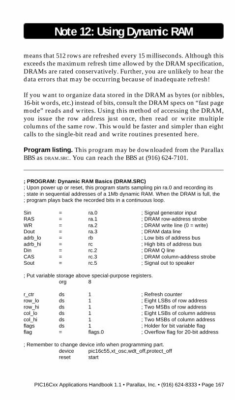
PIC16Cxx Applications Handbook 1.1 • Parallax, Inc. • (916) 624-8333 • Page 167
means that 512 rows are refreshed every 15 milliseconds. Although thisexceeds the maximum refresh time allowed by the DRAM specification,DRAMs are rated conservatively. Further, you are unlikely to hear thedata errors that may be occurring because of inadequate refresh!
If you want to organize data stored in the DRAM as bytes (or nibbles,16-bit words, etc.) instead of bits, consult the DRAM specs on “fast pagemode” reads and writes. Using this method of accessing the DRAM,you issue the row address just once, then read or write multiplecolumns of the same row. This would be faster and simpler than eightcalls to the single-bit read and write routines presented here.
Program listing. This program may be downloaded from the ParallaxBBS as DRAM.SRC. You can reach the BBS at (916) 624-7101.
Note 12: Using Dynamic RAM
; PROGRAM: Dynamic RAM Basics (DRAM.SRC); Upon power up or reset, this program starts sampling pin ra.0 and recording its; state in sequential addresses of a 1Mb dynamic RAM. When the DRAM is full, the; program plays back the recorded bits in a continuous loop.
Sin = ra.0 ; Signal generator inputRAS = ra.1 ; DRAM row-address strobeWR = ra.2 ; DRAM write line (0 = write)Dout = ra.3 ; DRAM data lineadrb_lo = rb ; Low bits of address busadrb_hi = rc ; High bits of address busDin = rc.2 ; DRAM Q lineCAS = rc.3 ; DRAM column-address strobeSout = rc.5 ; Signal out to speaker
; Put variable storage above special-purpose registers.org 8
r_ctr ds 1 ; Refresh counterrow_lo ds 1 ; Eight LSBs of row addressrow_hi ds 1 ; Two MSBs of row addresscol_lo ds 1 ; Eight LSBs of column addresscol_hi ds 1 ; Two MSBs of column addressflags ds 1 ; Holder for bit variable flagflag = flags.0 ; Overflow flag for 20-bit address
; Remember to change device info when programming part.device pic16c55,xt_osc,wdt_off,protect_offreset start
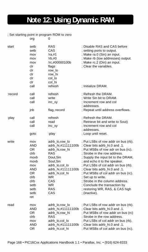
Page 168 • PIC16Cxx Applications Handbook 1.1 • Parallax, Inc. • (916) 624-8333
Note 12: Using Dynamic RAM
; Set starting point in program ROM to zeroorg 0
start setb RAS ; Disable RAS and CAS beforesetb CAS ; setting ports to output.mov !ra,#1 ; Make ra.0 (Sin) an input.mov !rb,#0 ; Make rb (low addresses) output.mov !rc,#00000100b ; Make rc.2 (Din) an input.clr flags ; Clear the variables.clr row_loclr row_hiclr col_loclr col_hicall refresh ; Initialize DRAM.
:record call refresh ; Refresh the DRAM.call write ; Write Sin bit to DRAM.call inc_xy ; Increment row and col
; addresses.jnb flag,:record ; Repeat until address overflows.
:play call refresh ; Refresh the DRAM.call read ; Retrieve bit and write to Sout)call inc_xy ; Increment row and col
; addresses.goto :play ; Loop until reset.
write mov adrb_lo,row_lo ; Put LSBs of row addr on bus (rb).AND adrb_hi,#11111100b ; Clear bits adrb_hi.0 and .1.OR adrb_hi,row_hi ; Put MSBs of row adr on bus (rc).clrb RAS ; Strobe in the row address.movb Dout,Sin ; Supply the input bit to the DRAM,movb Sout,Sin ; and echo it to the speaker.mov adrb_lo,col_lo ; Put LSBs of col addr on bus (rb).AND adrb_hi,#11111100b ; Clear bits adrb_hi.0 and .1.OR adrb_hi,col_hi ; Put MSBs of col addr on bus (rc).clrb WR ; Set up to write.clrb CAS ; Strobe in the column address.setb WR ; Conclude the transaction bysetb RAS ; restoring WR, RAS, & CAS highsetb CAS ; (inactive).ret
read mov adrb_lo,row_lo ; Put LSBs of row addr on bus (rb).AND adrb_hi,#11111100b ; Clear bits adrb_hi.0 and .1.OR adrb_hi,row_hi ; Put MSBs of row addr on bus (rc)clrb RAS ; Strobe in the row address.mov adrb_lo,col_lo ; Put LSBs of col addr on bus (rb).AND adrb_hi,#11111100b ; Clear bits adrb_hi.0 and .1.OR adrb_hi,col_hi ; Put MSBs of col addr on bus (rc).
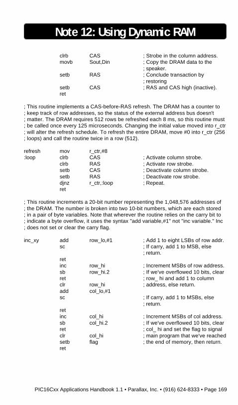
PIC16Cxx Applications Handbook 1.1 • Parallax, Inc. • (916) 624-8333 • Page 169
Note 12: Using Dynamic RAM
clrb CAS ; Strobe in the column address.movb Sout,Din ; Copy the DRAM data to the
; speaker.setb RAS ; Conclude transaction by
; restoringsetb CAS ; RAS and CAS high (inactive).ret
; This routine implements a CAS-before-RAS refresh. The DRAM has a counter to; keep track of row addresses, so the status of the external address bus doesn't; matter. The DRAM requires 512 rows be refreshed each 8 ms, so this routine must; be called once every 125 microseconds. Changing the initial value moved into r_ctr; will alter the refresh schedule. To refresh the entire DRAM, move #0 into r_ctr (256; loops) and call the routine twice in a row (512).
refresh mov r_ctr,#8:loop clrb CAS ; Activate column strobe.
clrb RAS ; Activate row strobe.setb CAS ; Deactivate column strobe.setb RAS ; Deactivate row strobe.djnz r_ctr,:loop ; Repeat.ret
; This routine increments a 20-bit number representing the 1,048,576 addresses of; the DRAM. The number is broken into two 10-bit numbers, which are each stored; in a pair of byte variables. Note that wherever the routine relies on the carry bit to; indicate a byte overflow, it uses the syntax "add variable,#1" not "inc variable." Inc; does not set or clear the carry flag.
inc_xy add row_lo,#1 ; Add 1 to eight LSBs of row addr.sc ; If carry, add 1 to MSB, else
; return.retinc row_hi ; Increment MSBs of row address.sb row_hi.2 ; If we've overflowed 10 bits, clearret ; row_ hi and add 1 to columnclr row_hi ; address, else return.add col_lo,#1sc ; If carry, add 1 to MSBs, else
; return.retinc col_hi ; Increment MSBs of col address.sb col_hi.2 ; If we've overflowed 10 bits, clearret ; col_ hi and set the flag to signalclr col_hi ; main program that we've reachedsetb flag ; the end of memory, then return.ret

Page 170 • PIC16Cxx Applications Handbook 1.1 • Parallax, Inc. • (916) 624-8333
BLANK PAGE
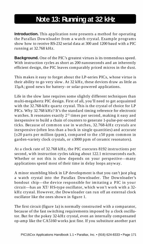
PIC16Cxx Applications Handbook 1.1 • Parallax, Inc. • (916) 624-8333 • Page 171
Note 13: Running at 32 kHz
Introduction. This application note presents a method for operatingthe Parallax Downloader from a watch crystal. Example programsshow how to receive RS-232 serial data at 300 and 1200 baud with a PICrunning at 32.768 kHz.
Background. One of the PIC’s greatest virtues is its tremendous speed.With instruction cycles as short as 200 nanoseconds and an inherentlyefficient design, the PIC leaves comparably priced micros in the dust.
This makes it easy to forget about the LP-series PICs, whose virtue istheir ability to go very slow. At 32 kHz, these devices draw as little as15µA; good news for battery- or solar-powered applications.
Life in the slow lane requires some slightly different techniques thanmulti-megahertz PIC design. First of all, you’ll need to get acquaintedwith the 32.768-kHz quartz crystal. This is the crystal of choice for LPPICs. Why 32.768 kHz? It’s the standard timing reference for electronicwatches. It resonates exactly 215 times per second, making it easy andinexpensive to build a chain of counters to generate 1-pulse-per-secondticks. Because of common use in watches, 32.768-kHz crystals areinexpensive (often less than a buck in single quantities) and accurate[±20 parts per million (ppm), compared to the ±50 ppm common ingarden-variety clock crystals, or ±3000 ppm of ceramic resonators).
At a clock rate of 32.768 kHz, the PIC executes 8192 instructions persecond, with instruction cycles taking about 122.1 microseconds each.Whether or not this is slow depends on your perspective—manyapplications spend most of their time in delay loops anyway.
A minor stumbling block in LP development is that you can’t just pluga watch crystal into the Parallax Downloader. The Downloader’sbondout chip—the device responsible for imitating a PIC in yourcircuit—has an XT/HS-type oscillator, which won’t work with a 32-kHz crystal. However, the Downloader can run off an external clockoscillator like the ones shown in figure 1.
The first circuit (figure 1a) is normally constructed with a comparator,because of the fast switching requirements imposed by a clock oscilla-tor. But for the pokey 32-kHz crystal, even an internally compensatedop-amp like the CA5160 works just fine. If you substitute another part
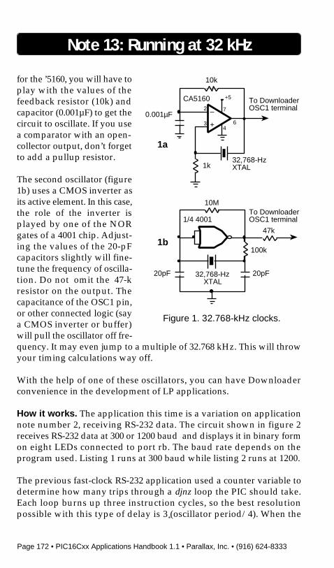
Page 172 • PIC16Cxx Applications Handbook 1.1 • Parallax, Inc. • (916) 624-8333
for the ’5160, you will have toplay with the values of thefeedback resistor (10k) andcapacitor (0.001µF) to get thecircuit to oscillate. If you usea comparator with an open-collector output, don’t forgetto add a pullup resistor.
The second oscillator (figure1b) uses a CMOS inverter asits active element. In this case,the role of the inverter isplayed by one of the NORgates of a 4001 chip. Adjust-ing the values of the 20-pFcapacitors slightly will fine-tune the frequency of oscilla-tion. Do not omit the 47-kresistor on the output. Thecapacitance of the OSC1 pin,or other connected logic (saya CMOS inverter or buffer)will pull the oscillator off fre-quency. It may even jump to a multiple of 32.768 kHz. This will throwyour timing calculations way off.
With the help of one of these oscillators, you can have Downloaderconvenience in the development of LP applications.
How it works. The application this time is a variation on applicationnote number 2, receiving RS-232 data. The circuit shown in figure 2receives RS-232 data at 300 or 1200 baud and displays it in binary formon eight LEDs connected to port rb. The baud rate depends on theprogram used. Listing 1 runs at 300 baud while listing 2 runs at 1200.
The previous fast-clock RS-232 application used a counter variable todetermine how many trips through a djnz loop the PIC should take.Each loop burns up three instruction cycles, so the best resolutionpossible with this type of delay is 3
*(oscillator period/4). When the
Note 13: Running at 32 kHz
1k
0.001µF
10k
32,768-HzXTAL
To DownloaderOSC1 terminal–
+
+5
7
46
2
3
20pF
10M
32,768-HzXTAL
To DownloaderOSC1 terminal
100k
20pF
CA5160
1/4 4001
47k
1a
1b
Figure 1. 32.768-kHz clocks.
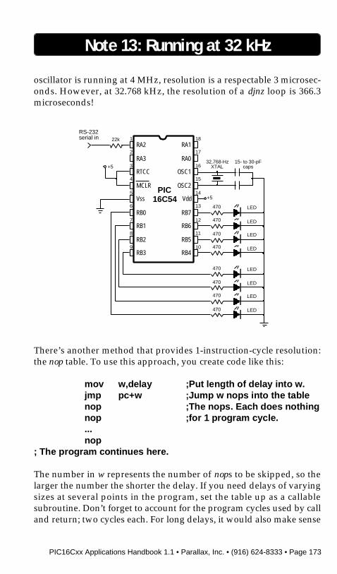
PIC16Cxx Applications Handbook 1.1 • Parallax, Inc. • (916) 624-8333 • Page 173
oscillator is running at 4 MHz, resolution is a respectable 3 microsec-onds. However, at 32.768 kHz, the resolution of a djnz loop is 366.3microseconds!
There’s another method that provides 1-instruction-cycle resolution:the nop table. To use this approach, you create code like this:
mov w,delay ;Put length of delay into w.jmp pc+w ;Jump w nops into the tablenop ;The nops. Each does nothingnop ;for 1 program cycle....nop
; The program continues here.
The number in w represents the number of nops to be skipped, so thelarger the number the shorter the delay. If you need delays of varyingsizes at several points in the program, set the table up as a callablesubroutine. Don’t forget to account for the program cycles used by calland return; two cycles each. For long delays, it would also make sense
Note 13: Running at 32 kHz
LED470
LED470
LED470
PIC16C54
1
2
3
4
5
6
7
8
9
18
17
16
15
14
13
12
11
10
RA2
RA3
RTCC
MCLR
Vss
RB0
RB1
RB2
RB3
RA1
RA0
OSC1
OSC2
Vdd
RB7
RB6
RB5
RB4
+5
+5
RS-232serial in
LED470
LED470
LED470
LED470
LED470
32,768-HzXTAL
22k
15- to 30-pFcaps
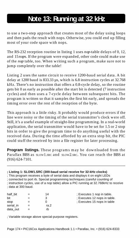
Page 174 • PIC16Cxx Applications Handbook 1.1 • Parallax, Inc. • (916) 624-8333
Note 13: Running at 32 kHz
to use a two-step approach that creates most of the delay using loopsand then pads the result with nops. Otherwise, you could end up fillingmost of your code space with nops.
The RS-232 reception routine in listing 1 uses nop-table delays of 0, 12,and 15 nops. If the program were expanded, other code could make useof the nop table, too. When writing such a program, make sure not tojump completely over the table!
Listing 2 uses the same circuit to receive 1200-baud serial data. A bitdelay at 1200 baud is 833.33 µs, which is 6.8 instruction cycles at 32.768kHz. There’s no instruction that offers a 0.8-cycle delay, so the routinegets bit 0 as early as possible after the start bit is detected (7 instructioncycles) and then uses a 7-cycle delay between subsequent bits. Theprogram is written so that it samples the first bit early, and spreads thetiming error over the rest of the reception of the byte.
This approach is a little risky. It probably would produce errors if theline were noisy or the timing of the serial transmitter’s clock were off.Still, it’s a useful example of straight-line programming. In a real-worldapplication, the serial transmitter would have to be set for 1.5 or 2 stopbits in order to give the program time to do anything useful with thereceived data. During the time afforded by an extra stop bit, the PICcould stuff the received by into a file register for later processing.
Program listings. These programs may be downloaded from theParallax BBS as SLOW1.SRC and SLOW2.SRC. You can reach the BBS at(916) 624-7101.
; Listing 1: SLOW1.SRC (300-baud serial receive for 32-kHz clocks); This program receives a byte of serial data and displays it on eight LEDs; connected to port rb. Special programming techniques (careful counting of; instruction cycles, use of a nop table) allow a PIC running at 32.768kHz to receive; data at 300 baud.
half_bit = 14 ; Executes 1 nop in table.bit = 3 ; Executes 12 nops in table.stop = 0 ; Executes 15 nops in tableserial_in = ra.2data_out = rb
; Variable storage above special-purpose registers.
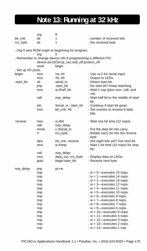
PIC16Cxx Applications Handbook 1.1 • Parallax, Inc. • (916) 624-8333 • Page 175
Note 13: Running at 32 kHz
org 8bit_cntr ds 1 ; number of received bitsrcv_byte ds 1 ; the received byte
; Org 0 sets ROM origin to beginning for program.org 0
; Remember to change device info if programming a different PIC.device pic16c54,lp_osc,wdt_off,protect_offreset begin
; Set up I/O ports.begin mov !ra, #4 ; Use ra.2 for serial input.
mov !rb, #0 ; Output to LEDs.:start_bit sb serial_in ; Detect start bit.
jmp :start_bit ; No start bit? Keep watching.mov w,#half_bit ; Wait 1 nop (plus mov, call, and
; ret).call nop_delay ; Wait half bit to the middle of start
; bit.jnb Serial_in, :start_bit ; Continue if start bit good.mov bit_cntr, #8 ; Set counter to receive 8 data
; bits.
:receive mov w,#bit ; Wait one bit time (12 nops).call nop_delaymovb c,/Serial_in ; Put the data bit into carry.rr rcv_byte ; Rotate carry bit into the receive
; byte.djnz bit_cntr,:receive ; Not eight bits yet? Get next bit.mov w,#stop ; Wait 1 bit time (15 nops) for stop
; bit.call nop_delaymov data_out, rcv_byte ; Display data on LEDs.goto begin:start_bit ; Receive next byte.
nop_delay jmp pc+wnop ; w = 0—executes 15 nops.nop ; w = 1—executes 14 nops.nop ; w = 2—executes 13 nops.nop ; w = 3—executes 12 nops.nop ; w = 4—executes 11 nops.nop ; w = 5—executes 10 nops.nop ; w = 6—executes 9 nops.nop ; w = 7—executes 8 nops.nop ; w = 8—executes 7 nops.nop ; w = 9—executes 6 nops.nop ; w = 10—executes 5 nops.nop ; w = 11—executes 4 nops.nop ; w = 12—executes 3 nops.nop ; w = 13—executes 2 nops.nop ; w = 14—executes 1 nop.
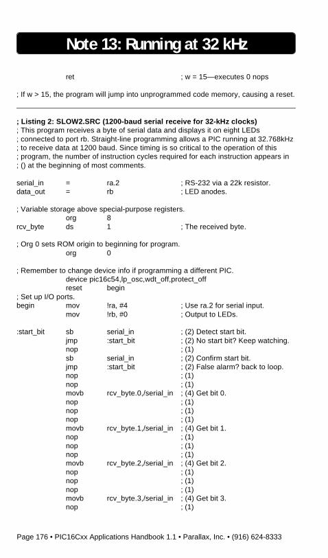
Page 176 • PIC16Cxx Applications Handbook 1.1 • Parallax, Inc. • (916) 624-8333
Note 13: Running at 32 kHz
ret ; w = 15—executes 0 nops
; If w > 15, the program will jump into unprogrammed code memory, causing a reset.
; Listing 2: SLOW2.SRC (1200-baud serial receive for 32-kHz clocks); This program receives a byte of serial data and displays it on eight LEDs; connected to port rb. Straight-line programming allows a PIC running at 32.768kHz; to receive data at 1200 baud. Since timing is so critical to the operation of this; program, the number of instruction cycles required for each instruction appears in; () at the beginning of most comments.
serial_in = ra.2 ; RS-232 via a 22k resistor.data_out = rb ; LED anodes.
; Variable storage above special-purpose registers.org 8
rcv_byte ds 1 ; The received byte.
; Org 0 sets ROM origin to beginning for program.org 0
; Remember to change device info if programming a different PIC.device pic16c54,lp_osc,wdt_off,protect_offreset begin
; Set up I/O ports.begin mov !ra, #4 ; Use ra.2 for serial input.
mov !rb, #0 ; Output to LEDs.
:start_bit sb serial_in ; (2) Detect start bit.jmp :start_bit ; (2) No start bit? Keep watching.nop ; (1)sb serial_in ; (2) Confirm start bit.jmp :start_bit ; (2) False alarm? back to loop.nop ; (1)nop ; (1)movb rcv_byte.0,/serial_in ; (4) Get bit 0.nop ; (1)nop ; (1)nop ; (1)movb rcv_byte.1,/serial_in ; (4) Get bit 1.nop ; (1)nop ; (1)nop ; (1)movb rcv_byte.2,/serial_in ; (4) Get bit 2.nop ; (1)nop ; (1)nop ; (1)movb rcv_byte.3,/serial_in ; (4) Get bit 3.nop ; (1)
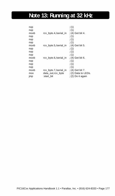
PIC16Cxx Applications Handbook 1.1 • Parallax, Inc. • (916) 624-8333 • Page 177
nop ; (1)nop ; (1)movb rcv_byte.4,/serial_in ; (4) Get bit 4.nop ; (1)nop ; (1)nop ; (1)movb rcv_byte.5,/serial_in ; (4) Get bit 5.nop ; (1)nop ; (1)nop ; (1)movb rcv_byte.6,/serial_in ; (4) Get bit 6.nop ; (1)nop ; (1)nop ; (1)movb rcv_byte.7,/serial_in ; (4) Get bit 7.mov data_out,rcv_byte ; (2) Data to LEDs.jmp :start_bit ; (2) Do it again
Note 13: Running at 32 kHz

Page 178 • PIC16Cxx Applications Handbook 1.1 • Parallax, Inc. • (916) 624-8333
BLANK PAGE
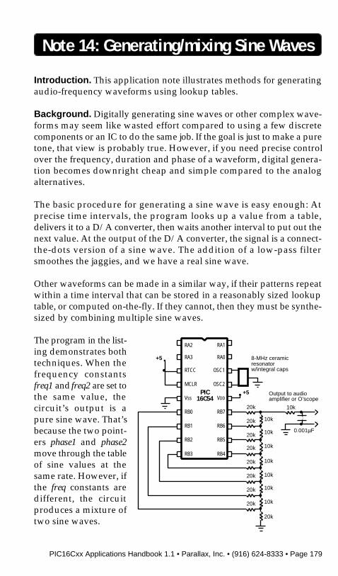
PIC16Cxx Applications Handbook 1.1 • Parallax, Inc. • (916) 624-8333 • Page 179
Note 14: Generating/mixing Sine Waves
Introduction. This application note illustrates methods for generatingaudio-frequency waveforms using lookup tables.
Background. Digitally generating sine waves or other complex wave-forms may seem like wasted effort compared to using a few discretecomponents or an IC to do the same job. If the goal is just to make a puretone, that view is probably true. However, if you need precise controlover the frequency, duration and phase of a waveform, digital genera-tion becomes downright cheap and simple compared to the analogalternatives.
The basic procedure for generating a sine wave is easy enough: Atprecise time intervals, the program looks up a value from a table,delivers it to a D/A converter, then waits another interval to put out thenext value. At the output of the D/A converter, the signal is a connect-the-dots version of a sine wave. The addition of a low-pass filtersmoothes the jaggies, and we have a real sine wave.
Other waveforms can be made in a similar way, if their patterns repeatwithin a time interval that can be stored in a reasonably sized lookuptable, or computed on-the-fly. If they cannot, then they must be synthe-sized by combining multiple sine waves.
The program in the list-ing demonstrates bothtechniques. When thefrequency constantsfreq1 and freq2 are set tothe same value, thecircuit’s output is apure sine wave. That’sbecause the two point-ers phase1 and phase2move through the tableof sine values at thesame rate. However, ifthe freq constants aredifferent, the circuitproduces a mixture oftwo sine waves.
RA2
PIC16C54
RA3 RA0
RTCC OSC1
MCLR OSC2
Vss VDD
RB0 RB7
RB1 RB6
RB2 RB5
RB3 RB4
RA1
20k
20k
20k
20k
20k
20k
20k
20k
20k
10k
10k
10k
10k
10k
10k
10k
8-MHz ceramicresonatorw/integral caps
Output to audioamplifier or O’scope
10k
0.001µF
+5
+5

Page 180 • PIC16Cxx Applications Handbook 1.1 • Parallax, Inc. • (916) 624-8333
Note 14: Generating/mixing Sine Waves
How it works. The resistors in figure 1 are connected in an array knownas an R-2R ladder. This arrangement has an interesting property. Itdivides each voltage present at its inputs by increasing powers of two,and presents the sum of all these divided voltages at its output. Since thePIC is capable of driving its outputs from rail to rail (0 to +5 volts), theR-2R ladder converts the binary number present on port B into aproportional voltage from 0 to 5 volts in steps of approximately 20millivolts.
Most commercial D/A converters work on this same principle, buthave internal voltage regulators, logic, and latches. Since our demon-stration doesn’t require any of those things, we can use the resistor arrayalone. Unfortunately, it can be difficult to find a prefabricated R-2Rladder at the volume parts houses. Figure 2 shows how to construct onefrom 25 surface-mount 10k resistors and a tiny printed circuit pattern.Alternatively, you may adapt the program listing to drive your favoritepackaged D/A converter.
The program that drives the D/A converter begins by setting port rb tooutput and clearing its variables. Next it enters this loop:
• Add freq1 to acc1> If acc1 overflows (generates a carry), increment phase1
• Put the sine value corresponding to phase1 into temp• Add freq2 to acc2
> If acc2 overflows (generates a carry), increment phase2• Add the sine value corresponding to phase2 into temp• Copy temp to the output• Do it again.
Parts placement
RB0RB7analogvoltage out
Actual-size pcb pattern
Figure 2. Constructing an R-2R digital-to-analog converter.
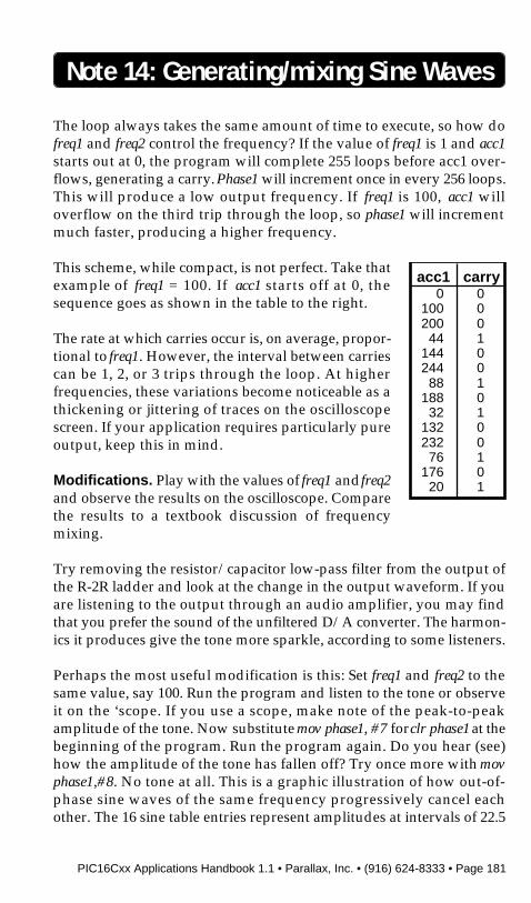
PIC16Cxx Applications Handbook 1.1 • Parallax, Inc. • (916) 624-8333 • Page 181
The loop always takes the same amount of time to execute, so how dofreq1 and freq2 control the frequency? If the value of freq1 is 1 and acc1starts out at 0, the program will complete 255 loops before acc1 over-flows, generating a carry. Phase1 will increment once in every 256 loops.This will produce a low output frequency. If freq1 is 100, acc1 willoverflow on the third trip through the loop, so phase1 will incrementmuch faster, producing a higher frequency.
This scheme, while compact, is not perfect. Take thatexample of freq1 = 100. If acc1 starts off at 0, thesequence goes as shown in the table to the right.
The rate at which carries occur is, on average, propor-tional to freq1. However, the interval between carriescan be 1, 2, or 3 trips through the loop. At higherfrequencies, these variations become noticeable as athickening or jittering of traces on the oscilloscopescreen. If your application requires particularly pureoutput, keep this in mind.
Modifications. Play with the values of freq1 and freq2and observe the results on the oscilloscope. Comparethe results to a textbook discussion of frequencymixing.
Try removing the resistor/capacitor low-pass filter from the output ofthe R-2R ladder and look at the change in the output waveform. If youare listening to the output through an audio amplifier, you may findthat you prefer the sound of the unfiltered D/A converter. The harmon-ics it produces give the tone more sparkle, according to some listeners.
Perhaps the most useful modification is this: Set freq1 and freq2 to thesame value, say 100. Run the program and listen to the tone or observeit on the ‘scope. If you use a scope, make note of the peak-to-peakamplitude of the tone. Now substitute mov phase1, #7 for clr phase1 at thebeginning of the program. Run the program again. Do you hear (see)how the amplitude of the tone has fallen off? Try once more with movphase1,#8. No tone at all. This is a graphic illustration of how out-of-phase sine waves of the same frequency progressively cancel eachother. The 16 sine table entries represent amplitudes at intervals of 22.5
Note 14: Generating/mixing Sine Waves
acc1 carry0 0
100 0200 044 1
144 0244 088 1
188 032 1
132 0232 076 1
176 020 1
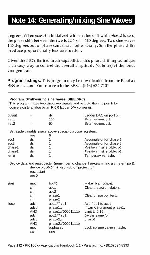
Page 182 • PIC16Cxx Applications Handbook 1.1 • Parallax, Inc. • (916) 624-8333
Note 14: Generating/mixing Sine Waves
degrees. When phase1 is initialized with a value of 8, while phase2 is zero,the phase shift between the two is 22.5 x 8 = 180 degrees. Two sine waves180 degrees out of phase cancel each other totally. Smaller phase shiftsproduce proportionally less attenuation.
Given the PIC’s limited math capabilities, this phase shifting techniqueis an easy way to control the overall amplitude (volume) of the tonesyou generate.
Program listings. This program may be downloaded from the ParallaxBBS as SINE.SRC. You can reach the BBS at (916) 624-7101.
; Program: Synthesizing sine waves (SINE.SRC); This program mixes two sinewave signals and outputs them to port b for; conversion to analog by an R-2R ladder D/A converter.
output = rb ; Ladder DAC on port b.freq1 = 100 ; Sets frequency 1.freq2 = 50 ; Sets frequency 2.
; Set aside variable space above special-purpose registers.org 8
acc1 ds 1 ; Accumulator for phase 1.acc2 ds 1 ; Accumulator for phase 2.phase1 ds 1 ; Position in sine table, p1.phase2 ds 1 ; Position in sine table, p2.temp ds 1 ; Temporary variable.
; Device data and reset vector (remember to change if programming a different part).device pic16c54,xt_osc,wdt_off,protect_offreset startorg 0
start mov !rb,#0 ; Make rb an output.clr acc1 ; Clear the accumulators.clr acc2clr phase1 ; Clear phase pointers.clr phase2
:loop add acc1,#freq1 ; Add freq1 to acc1addb phase1,c ; If carry, increment phase1.AND phase1,#00001111b ; Limit to 0-15.add acc2,#freq2 ; Do the same foraddb phase2,c ; phase2.AND phase2,#00001111bmov w,phase1 ; Look up sine value in table.call sine

PIC16Cxx Applications Handbook 1.1 • Parallax, Inc. • (916) 624-8333 • Page 183
Note 14: Generating/mixing Sine Waves
mov temp,w ; Store 1st sine value in temp.mov w,phase2call sine ; Get value from table.add temp,w ; Add sines together.mov output,temp ; Output to D/A.goto :loop ; Do forever.
; Notice that the sine values in the table below are scaled so that no pair adds to; more than 254. This prevents overflowing the variable temp when the phases are; added together. If you add more phases, adjust the maximum values in this table; appropriately. The values are in increments of 22.5 degrees (0.3927 radians).sine jmp pc+w
retw 64,88,109,122,127,122,109retw 88,64,39,19,5,0,5,19,39

Page 184 • PIC16Cxx Applications Handbook 1.1 • Parallax, Inc. • (916) 624-8333
BLANK PAGE
PIC16Cxx Applications Handbook 1.1 • Parallax, Inc. • (916) 624-8333 • Page 185
Note 15: Using Interrupts
Introduction. This application note shows how to use the interruptcapabilities built into the PIC 16Cxx series controllers with a simpleexample in Parallax assembly language.
Background. Many controller applications work like a fire depart-ment. When there’s no fire, they mend hoses, polish the fire truck, andwait for something to happen. When the fire bell rings, they swing intoaction and handle the emergency. When it’s over, they return towaiting.
If there were no fire bell, the job would be much different. The fire crewwould have to go out and look for fires, and somehow still make surethat the hoses were fixed and the truck maintained. In their scurry to geteverything done, they might respond late to some fires, and miss otherscompletely.
The newer PIC 16Cxx controllers have interrupts, which work like thefire bell in the first example. When an interrupt occurs, the PIC stopswhat it’s doing and handles the cause of the interrupt. When it’s done,the PIC returns to the point in the program at which it was interrupted.
The second example, with no fire bell, is an example of polling. This isthe approach used with the 16C5x PICs, which lack interrupts. For a fastPIC, polling isn’t nearly as bad as in the example. The PIC can often geteverything done with plenty of time to spare. But there are times wheninterrupts are the simplest way to do two or more things at once.
How interrupts work. For the examples here, we’re going to talkabout the 16C84. The same principles apply to the other interrupt-capable PICs, such as the 16C71 and 16C64, but registers and interruptsources may vary.
First of all, the 16Cxx PICs awaken from power-up with all interruptsdisabled. If you don’t want to use interrupts, don’t enable them. It’s thatsimple.
The PIC 16C84 can respond to interrupts from four sources:
• A rising or falling edge (your choice) on pin RB0/INT.
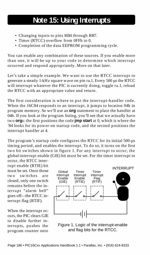
Page 186 • PIC16Cxx Applications Handbook 1.1 • Parallax, Inc. • (916) 624-8333
Note 15: Using Interrupts
• Changing inputs to pins RB4 through RB7.• Timer (RTCC) overflow from 0FFh to 0.• Completion of the data EEPROM programming cycle.
You can enable any combination of these sources. If you enable morethan one, it will be up to your code to determine which interruptoccurred and respond appropriately. More on that later.
Let’s take a simple example. We want to use the RTCC interrupt togenerate a steady 1-kHz square wave on pin ra.1. Every 500 µs the RTCCwill interrupt whatever the PIC is currently doing, toggle ra.1, reloadthe RTCC with an appropriate value and return.
The first consideration is where to put the interrupt-handler code.When the 16C84 responds to an interrupt, it jumps to location 04h inprogram memory. So we’ll use an org statement to place the handler at04h. If you look at the program listing, you’ll see that we actually havetwo orgs: the first positions the code jmp start at 0, which is where the’84 looks for its power-on startup code, and the second positions theinterrupt handler at 4.
The program’s startup code configures the RTCC for its initial 500-µstiming period, and enables the interrupt. To do so, it turns on the firsttwo bit switches shown in figure 1. For any interrupt to occur, theglobal-interrupt enable (GIE) bit must be set. For the timer interrupt tooccur, the RTCC inter-rupt enable (RTIE) bitmust be set. Once thosetwo switches areclosed, only one switchremains before the in-terrupt “alarm bell”goes off—the RTCC in-terrupt flag (RTIF).
When the interrupt oc-curs, the PIC clears GIEto disable further in-terrupts, pushes theprogram counter onto
GlobalInterruptEnable(GIE)
TimerInterruptEnable(RTIE)
TimerInterrupt
Flag(RTIF)
INTERRUPT
Figure 1. Logic of the interrupt-enableand flag bits for the RTCC.
PIC16Cxx Applications Handbook 1.1 • Parallax, Inc. • (916) 624-8333 • Page 187
Note 15: Using Interrupts
the stack, then jumps to location 4. This process takes four instructioncycles for an internal interrupt like the RTCC, five for an externalinterrupt like RB0/INT.
Once at location 4, the PIC executes the code there until it encounters aret, retw, or reti instruction. Any of these will pop the value from the topof the stack and cause a jump back to the point at which the program wasinterrupted. However, the normal way to return from an interrupt is thereti instruction. It automatically re-enables interrupts by setting GIE.The other two returns do not.
In the program listing, you will notice that the first thing the interrupthandler does is clear RTIF. Whenever the RTCC rolls over from 0FFh to0, the PIC automatically sets RTIF. It does this regardless of the state ofthe interrupt bits. And it never turns RTIF back off. So it’s the respon-sibility of the interrupt handler to clear RTIF. This is true of all of theinterrupt flags. If the handler doesn’t clear the appropriate flag, thesame interrupt will occur again as soon as interrupts are re-enabled. Theresulting endless loop is what the Microchip documentation calls“recursive interrupts.”
With a single interrupt source, you can think of an interrupt as ahardware version of the call instruction. The primary difference is thatthis kind of call can occur anywhere in your program, whether or notthe program is ready for it. This can pose a problem. Let’s say yourprogram is executing the Parallax instruction add sum,delta when theinterrupt occurs. That add instruction actually consists of two instruc-tions; one that loads the variable delta into the w register, and a secondthat adds w to sum.
Imagine that right after delta is loaded into w, the interrupt takes over.It performs, for instance, the instruction mov rb,data. This instructionloads the variable data into w, then moves w into rb. When it’s done, wcontains a copy of data.
When the handler returns, the PIC completes the interrupted addition.But w contains data, not the intended delta, causing an error.
There are two ways to prevent this. One is to disable interrupts beforea two-part instruction, then enable them again afterwards. If the inter
Page 188 • PIC16Cxx Applications Handbook 1.1 • Parallax, Inc. • (916) 624-8333
Note 15: Using Interrupts
rupt event occurs while interrupts are disabled, the PIC will set theinterrupt flag, but won’t jump to the handler until your program re-enables interrupts. The PIC will not miss the interrupt, it will just beslightly delayed in handling it. To use this method, the example abovewould be changed to:
clrb GIE ; Interrupts disabled.add sum,delta ; w = delta: sum = sum+w.setb GIE ; Interrupts enabled.
The alternative approach is to begin your interrupt handler with codethat saves a copy of the w register. Then, just before reti, move the copyback into w.
This takes care of compound instructions that use w, but leaves anothergroup of instructions vulnerable; the ones that use the status register.Conditional jumps and skips like jump-if-zero ( jz) and compare-and-jump-if-equal (cje) and their many cousins are probably obvious. Moresubtle are the rotate instructions rr and rl (which pull the carry bit intothe most- or least-significant bit of the byte being rotated). If theinterrupt handler affects any of the status bits, it may alter the outcomeof the interrupted instruction.
To protect w and status, you must make copies of them at the beginningof a handler, then restore those copies at the end. In order to prevent theaction of restoring w from affecting status, you can use a sneaky trick.Moving a file register into w will set or clear the zero bit, but moving anibble-swapped copy of the register into w does not. Neither doesswapping the nibbles of a file register. The program listing shows howto use these loopholes to accurately copy both w and status.
Keep your interrupt handlers as short and simple as possible. Examinethem carefully for their effect on other portions of the program thatmight be executing at the time the interrupt occurs. If necessary, protectsensitive code by bracketing it with instructions that temporarilydisable interrupts. Also, keep in mind that test running your programmay not catch all possible interrupt-induced bugs. Use the PSIMsimulator and a sharp eye to detect potential problems.
Once you understand how the mechanism works with a single inter
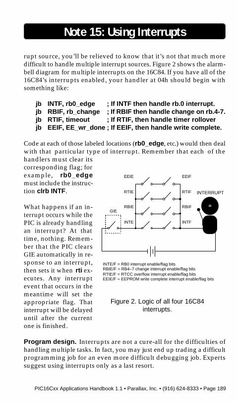
PIC16Cxx Applications Handbook 1.1 • Parallax, Inc. • (916) 624-8333 • Page 189
Note 15: Using Interrupts
rupt source, you’ll be relieved to know that it’s not that much moredifficult to handle multiple interrupt sources. Figure 2 shows the alarm-bell diagram for multiple interrupts on the 16C84. If you have all of the16C84’s interrupts enabled, your handler at 04h should begin withsomething like:
jb INTF, rb0_edge ; If INTF then handle rb.0 interrupt.jb RBIF, rb_change ; If RBIF then handle change on rb.4-7.jb RTIF, timeout ; If RTIF, then handle timer rolloverjb EEIF, EE_wr_done ; If EEIF, then handle write complete.
Code at each of those labeled locations (rb0_edge, etc.) would then dealwith that particular type of interrupt. Remember that each of thehandlers must clear itscorresponding flag; forexample, rb0_edgemust include the instruc-tion clrb INTF.
What happens if an in-terrupt occurs while thePIC is already handlingan interrupt? At thattime, nothing. Remem-ber that the PIC clearsGIE automatically in re-sponse to an interrupt,then sets it when rti ex-ecutes. Any interruptevent that occurs in themeantime will set theappropriate flag. Thatinterrupt will be delayeduntil after the currentone is finished.
Program design. Interrupts are not a cure-all for the difficulties ofhandling multiple tasks. In fact, you may just end up trading a difficultprogramming job for an even more difficult debugging job. Expertssuggest using interrupts only as a last resort.
GIE
INTERRUPT
INTE
RBIE
RTIE
EEIE
INTF
RBIF
RTIF
EEIF
INTE/F = RB0 interrupt enable/flag bitsRBIE/F = RB4–7 change interrupt enable/flag bitsRTIE/F = RTCC overflow interrupt enable/flag bitsEEIE/F = EEPROM write complete interrupt enable/flag bits
Figure 2. Logic of all four 16C84interrupts.

Page 190 • PIC16Cxx Applications Handbook 1.1 • Parallax, Inc. • (916) 624-8333
Note 15: Using Interrupts
; Program: INTRPT.SRC (Interrupt demonstration); This program illustrates the use of the RTCC interrupt; in the PIC 16C84. The foreground program blinks an LED on; pin ra.0, while an interrupt task outputs a 1-kHz square; wave through pin ra.1 (assuming a 4-MHz clock).
; Device (16c84) and setup options.device pic16c84,xt_osc,wdt_off,pwrt_off,protect_off
; Equates for LED, tone pins. Connect the LED through a; 220-ohm resistor. Connect a speaker or earphone through; a 1-k resistor.LED = ra.0SPKR = ra.1tone = 6 ; Load into RTCC for 500-us delay.
; Allocate space for some variables. Notice that in the ’84; variable start at 0Ch—higher than in the 16C5x series.
org 0Chw_copy ds 1s_copy ds 1countL ds 1countH ds 1
; On startup, the PIC looks at address 0 for its first; instruction. Since the interrupt handler begins at; address 4, we’ll just jump over it to get to the; startup routine.
org 0jmp start ; Beginning of main program.
; Next is the interrupt handler, which must begin at; address 4. This handler copies restores w and the status; register. Because a normal “mov w,fr” alters the z bit of; the status register, this routine uses “mov w,<>fr,” which; does not. The routine actually swaps the byte twice,; resulting in the correct value being written to w without; affecting the z bit.
org 4handler
clrb RTIF ; Clear the timer interrupt flag.mov w_copy,w ; Make a copy of w.mov s_copy,status ; Make a copy of status.XOR ra,#2 ; Toggle bit ra.1.mov rtcc,#tone ; Reload rtcc for 500-us delay.mov status,s_copy ; Restore status registerswap w_copy ; Prepare for swapped move.mov w,<>w_copy ; Swap/move to w, status unaffected.reti ; Return to main program.
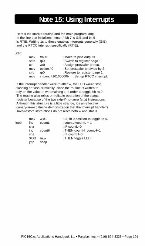
PIC16Cxx Applications Handbook 1.1 • Parallax, Inc. • (916) 624-8333 • Page 191
; Here’s the startup routine and the main program loop.; In the line that initializes “intcon,” bit 7 is GIE and bit 5; is RTIE. Writing 1s to these enables interrupts generally (GIE); and the RTCC interrupt specifically (RTIE).
Startmov !ra,#0 ; Make ra pins outputs.setb rp0 ; Switch to register page 1.clr wdt ; Assign prescaler to rtcc.mov option,#0 ; Set prescaler to divide by 2.clrb rp0 ; Restore to register page 1.mov intcon, #10100000b ; Set up RTCC interrupt.
; If the interrupt handler were to alter w, the LED would stop; flashing or flash erratically, since the routine is written to; rely on the value of w remaining 1 in order to toggle bit ra.0.; The routine also relies on reliable operation of the status; register because of the two skip-if-not-zero (snz) instructions.; Although this structure is a little strange, it’s an effective; canary-in-a-coalmine demonstration that the interrupt handler’s; save/restore instructions do preserve both w and status.
mov w,#1 ; Bit in 0 position to toggle ra.0.:loop inc countL ; countL=countL + 1
snz ; IF countL=0,inc countH ; THEN countH=countH+1snz ; IF countH=0,XOR ra,w ; THEN toggle LED.jmp :loop
Note 15: Using Interrupts