Non-ResidentialNewBuild 4.4.1GroundFloors floors Solution optimiser and pathfinder 372 Sales 0844...
25
Non - Residential New Build 4.4.1 Ground Floors August 2008: Issue 1
Transcript of Non-ResidentialNewBuild 4.4.1GroundFloors floors Solution optimiser and pathfinder 372 Sales 0844...

Non - Residential New Build4.4.1 Ground Floors
August 2008: Issue 1

4.0Non-residential new build
Non-residential New Build
Sales 0844 800 0135 Technical Advisory Centre 01744 766666 www.knaufinsulation.co.uk
Introduction find online pageSolution optimiser and pathfinder 372Design considerations 374
Design Details 612
Ground Floors Contents
find online page
Insulation below slab (Polyfoam) Gf01 620
Insulation above slab (Rocksilk) Gf02 622
Insulation above slab (Polyfoam) Gf03 624
Suspended concrete floor (Polyfoam) Gf04 626
Suspended concrete floor (Rocksilk) Gf05 628
Suspended timber floor Gf06/Gf09 630
Underfloor heating (Osma system) Gf07 632
Underfloor heating (Polyfoam
underfloor heating board system) Gf08 634

Ground floorsSolution optimiser and pathfinder
Sales 0844 800 0135 Technical Advisory Centre 01744 766666 www.knaufinsulation.co.uk372
4.4.1 Non-residential new build: Floors
Both ground bearing and suspended groundfloors can offer excellent thermalperformance by including high levels ofinsulation without dramatically altering the building shape or geometry.
Insulation below slab (medium-sized building)Product*: Polyfoam Floorboard Standardor DomesticDescription: Ultra strong XPS insulation below floor slab, P/A Ratio 0.40Page No: 620
Insulation below slab (large building)Product*: Polyfoam Floorboard Standardor DomesticDescription: Ultra strong XPS insulation below floor slab, P/A Ratio 0.20
Page No: 620
Knauf Insulation solution
Gf01
Insulation above slab (large building)Product*: Polyfoam Floorboard Standardor DomesticDescription: Ultra strong XPS insulation above floor slab and below chipboard or screed, P/A Ratio 0.20Page No: 624
Gf03
Insulation above slab (medium-sized building)Product*: Polyfoam Floorboard Standardor DomesticDescription: Ultra strong XPS insulation above floor slab and below chipboard or screed, P/A Ratio 0.40Page No: 624
Elemental U-value requirement
Ground floorsConstruction compatibility with Part L2A
KeyU-values achievable by constructions within this document.
* Recommended Knauf Insulation product(s). Other products may be applicable.
Find online. Visit www.knaufinsulation.co.uk and key in construction code to find the most up to date information on your chosen solution.
Pb01
Area weighted average max
U-value for compliance England
and Wales and Northern Ireland
U-values 0.32 0.30 0.28 0.26 0.25 0.22 0.20 0.18 0.16 0.14 0.12 0.24
Knauf Insulation provides products for arange of ground floor constructions, givingoptions that will comply with the BuildingRegulations.
Gf01
Gf03

Sales 0844 800 0135 Technical Advisory Centre 01744 766666 www.knaufinsulation.co.uk 373
4.4.1Non-residential new build: Floors
Suspended timber• Enables construction on contaminated
sites and can reduce excavation costs on sloping sites
• Fast and dry method
• Utilises lightweight and readily available products
• Low thermal mass allows room to warm up quicker during heating season
• Traditional looking floor
Concrete ground bearing slabInsulation below slab• Lowest cost solution
• Slab acts as thermal store
• Fewer restrictions on insulation thickness
• Traditional method utilising common materials
Insulation above slab• Screed is quicker drying than solid slab
and provides a smoother surface finish
• Insulation zone can be used toaccommodate services or underfloor heating
Suspended concrete• Enables construction on contaminated
sites and can reduce excavation costs on sloping sites
• Creates a working platform for following trades
Below screed• Smooth surface finish perceived as being
more robust than chipboard decks
Insulation below chipboard• Fast and dry method
• Low thermal mass allows room to warm up quicker during heating season
• Traditional looking floor
Suspended concrete floor (large building)Products*: Polyfoam Floorboard Standardor DomesticDescription: Ultra strong XPS insulation onsuspended concrete floor and below chipboard or screed, P/A Ratio 0.20Page No: 626
Gf04
Suspended concrete floor (medium-sized building)Products*: Polyfoam Floorboard Standardor DomesticDescription: Ultra strong XPS insulation onsuspended concrete floor and below chipboard or screed, P/A Ratio 0.40Page No: 626
Gf04
Area weighted
average max
U-value for compliance
England and Wales
and Northern Ireland
Suspended concrete floor (detached)Product*: Rocksilk Thermal Floor Slab PlusDescription: Compression resistant rockmineral wool insulation on suspendedconcrete floor and below chipboard or screed, P/A Ratio 0.60Page No: 628
Suspended timber floor (terrace)Product*: Crown Loft Roll 44Description: Glasswool insulation fitted between timber joists, P/A Ratio 0.30
Page No: 630Gf06
Gf05
Knauf Insulation solution
Elemental U-value requirement
Ground floorsConstruction compatibility with Part L2A
U-values 0.32 0.30 0.28 0.26 0.25 0.22 0.20 0.18 0.16 0.14 0.12 0.24

Ground floorsGround floor design
Sales 0844 800 0135 Technical Advisory Centre 01744 766666 www.knaufinsulation.co.uk374
4.4.1 Non-residential new build: Floors
GeneralWhen designing a floor the following should all be considered in addition to theachievement of the desired U-value:
• Applied floor loading
• Position of the insulation within the floor structure
• Minimising thermal bridging and air leakage and preventing condensation
IntroductionGround bearing floors can include insulationeither below or above the concrete slab,depending on the choice of the designer. If the insulation is installed below the slab, this increases the thermal capacity of thebuilding, helping to maintain steadytemperatures. If insulation is installed above the slab, the building will respond much morequickly to the heating system.
Suspended floors are usually insulated in such a way that they offer little thermal mass andrespond quickly to the heating system. In the caseof suspended concrete, the insulation is installedabove the deck, either under a screed or timberboarding. Suspended timber floors are normallyinsulated between the joists.
Ground floors fall predominantly into twocategories, ground bearing and suspended.The type chosen by the designer is largelydependent on site conditions.
Both ground bearing and suspended ground floors can offer excellent thermal performance by including high levels of insulation without dramatically alteringthe building shape or geometry.
Floor insulation is of particular importance if installing underfloor heating. The use ofchannelled rigid insulation boards can combinethe function of floor insulation and housing forthe heating pipes.
Applied floor loadingAll materials are compressed under load.Insulation materials used under slabs, screedsand chipboard should be capable ofaccommodating the applied loads with theminimum of compression. Standardised valuesare available to the designer for the dead loadsapplied by building components and theestimated active loads for various types ofbuilding use. These are shown in Table 14. Theseinform the structural design requirements of thefloor, but are of less value when considering thecompression resistance requirements of the flooras the active loads are likely to be localised or point loads, notuniformly distributed loads.
Active and dead loadsThe actual applied floor load acting on theinsulation material has two components:
• The dead load, which is due to the weight of the materials laid on the insulant, and
• The design load associated with the use of the floor
For specific applications the guidance andrecommendations contained in BS 6399: Part 1:1996 should be followed, and this will help thedesigner ensure that the strength of the floor willbe sufficient to support any applied loads overthe loaded area. The designer must also considerthe dynamic loads and how they are applied. BS6399 is based on the uniformly distributed load(UDL) but in reality the load associated with theuse of the floor will not be applied uniformly. Infact many loads are applied in a localised wayor even as point loads so that whilst the overallload on a floor is in line with BS6399 thelocalised loading may be many times higher. Forexample, a cupboard raised on feet has asignificantly increased point loading compared toone sat on the whole base. This results inincreased localised loading acting on theinsulation.

Sales 0844 800 0135 Technical Advisory Centre 01744 766666 www.knaufinsulation.co.uk 375
4.4.1Non-residential new build: Floors
Table 8: Dead loads applied by various building componentsElement Dead load
(kN/m2)
Flooring grade chipboard 0.1 to 0.2
65mm concrete screed 1.50
75mm concrete screed 1.75
150mm concrete floor slab 3.50
Design load for general office use 2.50
Design load for light industrial use 5.00
Design load for general storage use 4.80
Design load for heavy storage use 7.20
Position of insulationAs was noted in the introduction the position ofthe insulation in the floor has an influence overthe thermal characteristics that the floor brings tothe building, however it also has relevance whenconsidering the active loads that apply due to theuse of the floor. Obviously in timber joisted floorswhere the insulation material is placed betweenthe joists the entire load is carried by the joistsand there is no load on the insulation, howeverwhere the insulation is a single layer below aslab, screed or timber board layer the entire loadis acting on the insulation.
Point loads are spread by the layers above theinsulation so that the load acting on the insulationis lower than the load applied to the floorsurface. The spread of a load is a function of thedepth of the layer above the insulation. Thismeans that a point load applied to a floor wherethe insulation is positioned below a thin screedwill result in a higher active load to the insulationmaterial than where the insulation was positionedbelow a thicker floor slab because the load isbearing on a smaller area of insulation under thescreed. Of course the differing dead load appliedby the screed and the floor slab should also beallowed for when calculating the total loadapplied to the insulation.
Table 8a: Compressive creep results for Polyfoam
Product Load applied Initial Compression Further compression after kPa % 50 years %
Polyfoam Standard 60 2 1.5
Polyfoam Extra 120 2 1.5
Polyfoam Super 175 2 1.5
Compression resistanceThe total load applied to the insulation materialresults in compression of the insulation material. Itis vitally important that the insulation material hassufficient compression resistance to restrict theeffects of the compressive load. Compressionresistance is measured in two ways, mostcommonly the immediate effect of compressiveload is measured and this is quoted as acompression resistance in kPa. The applicationssection shows the compression resistance ofindividual insulation materials, this is useful inidentifying the general suitability of a material forthe application intended. The secondmeasurement of compression resistance measuresthe long term effects of loading on a material andis described as compressive creep. Where higherloads are applied this figure has high relevanceas long term loading will result in greaterprogressive compression of thickness in someinsulation material than others.
Compressive creepCompressive creep is the measured value of thelong term behaviour of a material under load.High resistance to compressive creep is critical forlong-term structural performance. The idealinsulation material used in flooring needs to bestrong without being brittle over the long term asthis will minimise any building movement. Amaterial with superior resistance to compressivecreep enables designers to truly optimize theirdesign to maximize the potential uses of thestructure without the risk of failure in the mediumto long term.Compressive creep tests are necessarily long termprojects as they predict the effect of loading over50 years. Polyfoam XPS insulation has been testedfor these results and has achieved the followingresults

Ground floorsGround floor design
Sales 0844 800 0135 Technical Advisory Centre 01744 766666 www.knaufinsulation.co.uk376
4.4.1 Non-residential new build: Floors
Calculation of U-valuesUnlike walls and roofs, the heat loss through a ground floor varies with its size and shape. TheBuilding Regulations require that when groundfloor U-values are calculated, BS EN ISO 13370:1998 should be used.
This Standard uses the ratio of the exposed floorperimeter to the floor area to take account of thevariation in heat loss due to floor size and shape.
The measurement of the perimeter and areashould be to the finished inside surfaces of theperimeter walls that enclose the heated space.Projecting bays should be included, but unheatedspaces should be excluded.
When considering extensions to existingbuildings the floor dimensions may be taken asthose of the complete building including theextension.
Determining the U-value
Worked exampleThe following worked example illustrates how to use the graph.
ExampleFloorplan example as shown
Perimeter P = 24+12+9+18+15 +30 = 26m
Area A = (24x30) - (9x18) = 62m2
Ratio P/A = 108/558 = 0.19
Reading off from the graph, below right, showsthat a ground floor with a P/A ratio of 0.19would achieve a U-value of 0.25 W/m2K ifinsulated with 35mm Polyfoam Floorboard in a ground bearing concrete slab.
Graph of U-values for Polyfoam Floorboard used in ground bearing concrete slabs
The tables for each ground floor solution shown in Section 6 ‘Design Details’, pages 620-635, show typical U-values for a range offloor constructions, assuming a conductivity of 1.50 W/mK for the ground below the floor.
The high number of variables that have to betaken into account can significantly affect the U-value for a particular set of conditions.Project specific U-value calculations can besupplied by the Technical Advisory Centre.
Condensation A vapour control layer is not normally requiredfor most ground floor constructions. However, a vapour control layer is recommended betweenthe insulation and a chipboard floor, especially ifthere is a risk of excessive moisture from the floorslab drying out.

Sales 0844 800 0135 Technical Advisory Centre 01744 766666 www.knaufinsulation.co.uk 377
4.4.1Non-residential new build: Floors
Alternative positions for floor insulation – showing good practicedetails to minimise thermal bridging and air leakage
Polypropylene netting
2. Concrete ground floor with floating screed
Floor insulation
Concrete slab
Damp proof membrane
Perimeter insulation with athermal resistance of at least0.75 m2K/W, (e.g. 25mmPolyfoam Floorboard)
Continue wall insulation atleast 150mm below top of
perimeter insulation andsupport on a row of ties
Flexible sealant betweenskirting and floor slab to
limit air leakage
1. Concrete ground floor with insulation under slab
Damp proof membrane
Floating screed
Concrete slab
Continue wall insulation atleast 150mm below top of
perimeter insulation andsupport on a row of ties
Flexible sealant betweenskirting and floor slab to
limit air leakage
4. Precast suspended floor with screed
Chipboard ortimber boarding
Continue wall insulation at least 200mm below top ofperimeter insulation and support on a row of ties
Flexible sealant between skirting and floor slab to limit air leakage
3. Suspended timber ground floor
Chipboard/timber boarding on separating layer
Precast plankContinue wall insulation at least 150mm below top of floor insulation and support on a row of ties
Flexible sealant between skirting and floor slab to limit air leakage
Gaps below 25mm fill with expanding foam, otherwise pack with mineral wool
Thermal bridging and air leakageThe junctions between construction elements arepotential areas of weakness with regard tothermal bridging and air leakage. The effect ofboth of these are included in the whole buildingcalculation methods such as SBEM that are usedto show compliance with the BuildingRegulations. Accredited Construction Details havebeen produced for Dwellings, these are designedto minimise thermal bridging and air leakage,they are valid for similar forms of constructionused in Non Dwellings. The illustrations shownhere are examples ofgood practice.

Ground floorsInsulation below slab
Sales 0844 800 0135 Technical Advisory Centre 01744 766666 www.knaufinsulation.co.uk620
6.3.1 Design details: Ground floors
PerformanceThermal performanceThe thermal conductivities of PolyfoamFloorboard products are as follows:-
Standard – 0.029W/mK
Extra – 0.029 -0.034W/mK
Super – 0.034 - 0.036W/mK
Unlike most other insulants, moisture has anegligible effect on the thermal performance ofPolyfoam Floorboard.
Table 63 gives U-values for a range ofperimeter/area ratios. For an explanation ofhow to calculate perimeter/area ratio seepage 206.
Fire performanceWhen Polyfoam Floorboard is installed in aconcrete floor construction, it will not contributeto the development stages of a fire.
InstallationLevel the sand blinding over the hardcore toreceive the insulation.
Lay the Polyfoam Floorboard directly on thesand blinding and then lay the DPM over theinsulation and lap with the wall DPC.Alternatively, lay Polyfoam Floorboard over theDPM in a staggered pattern to cover the wholefloor area. The joints should be tightly butted.Use spreader boards, as necessary, to preventpoint loads puncturing the DPM. A slip layer isrequired between the insulation and theconcrete slab.
Place a strip of insulation, minimum 25mmthick, vertically at the slab perimeter to minimisethermal bridging. The height of the perimeterinsulation to equal the slab thickness. Ensure theperimeter insulation boards are securely held inplace to prevent dislodgement by followingwork, e.g. by taping them to the main floorinsulation.
Lay the concrete slab. The concrete slab maybe screeded or alternatively have a powerfloat finish.
ProductsPolyfoam Floorboard is a range of 100% ozonefriendly extruded polystyrene rigid boardinsulation – it is lightweight yet has excellentstructural strength and long term effectiveness
It is available in three grades:
Standard – domestic and light commercialloading
Extra – commercial, industrial flooring and coldstorage
Super – very high load commercial, industrialand cold storage floors
Typical constructionA solid concrete ground floor slab cast oninsulation on a damp proof membrane (DPM)laid over blinded hardcore. Alternativelyconcrete floor slab cast on a damp proofmembrane laid over the insulation. A strip ofPolyfoam Floorboard insulation, minimum25mm thick, should be placed vertically at theslab perimeter to minimise thermal bridging.
The wall insulation should start a minimum of150mm below the top of the floor insulation.There should be a flexible sealant between thewall finish and the floor slab to minimise airleakage at this junction.
Advantages� Long term exposure to water has
negligible impact on the thermalperformance of Polyfoam
� Can be used above or below the DPM
Above Damp Proof Membrane
� Protects DPM from damage beforeand during the concrete pouringprocess
Below Damp Proof Membrane
� Protects DPM from possible puncturefrom hardcore and extremes oftemperature at perimeter
� Resists tough site conditions
� Industry leading range of compressivestrengths, allows the specifier to selectthe most appropriate solution basedon expected floor loads
Polyfoam Floorboard
Polyfoam Floorboard below slab
Damp proof membrane
25mm Polyfoam Floorboardat perimeter of slab
Concrete floor slab
Wall insulationtaken down at least 150mmbelow floor insulation
Slip layer, or alternative positionfor damp proof membrane
Sandblinding
Flexible sealantGf01

621
6.3.1Design details: Ground floors
Sales 0844 800 0135 Technical Advisory Centre 01744 766666 www.knaufinsulation.co.uk
Table 63: Typical U-values for floors insulated below a concrete ground floor slab U-values
(W/m2K)Thickness Ratio of perimeter (m) to area (m2)(mm) 0.1 0.2 0.3 0.4 0.5 0.6 0.7 0.8
Polyfoam Floorboard Standard
160 (85 + 75) 0.09 0.11 0.13 0.13 0.14 0.14 0.15 0.15
140 (65 + 75) 0.09 0.12 0.14 0.15 0.15 0.16 0.16 0.17
125 (50 + 75) 0.10 0.13 0.15 0.16 0.17 0.17 0.18 0.18
100 (50 + 50) 0.11 0.15 0.17 0.19 0.20 0.20 0.21 0.22
85 0.12 0.16 0.19 0.21 0.22 0.23 0.24 0.24
75 0.12 0.17 0.20 0.22 0.24 0.25 0.26 0.26
65 0.13 0.19 0.22 0.24 0.26 0.27 0.28 0.29
50 0.14 0.21 0.25 0.28 0.30 0.32 0.33 0.34
35 0.15 0.23 0.29 0.33 0.36 0.38 0.40 0.42
Polyfoam Floorboard Extra
175 (100 + 75) 0.09 0.11 0.13 0.13 0.14 0.14 0.15 0.15
150 (75 + 75) 0.09 0.12 0.13 0.14 0.15 0.15 0.15 0.16
125 (50 + 75) 0.10 0.13 0.15 0.16 0.17 0.17 0.18 0.18
75 0.12 0.17 0.20 0.22 0.24 0.25 0.26 0.26
65 0.13 0.19 0.22 0.24 0.26 0.27 0.28 0.29
50 0.14 0.21 0.25 0.28 0.30 0.32 0.33 0.34
35 0.15 0.23 0.29 0.33 0.36 0.38 0.40 0.42
25 0.16 0.26 0.32 0.37 0.41 0.45 0.47 0.49Note: The U-values have been calculated using BS EN ISO 13370: 1998 and assume a clay subsoil with a thermalconductivity of 1.50 W/mK. U-values for floors insulated with Polyfoam Floorboard Super can be supplied by the KnaufInsulation Technical Advisory Centre
Cavity wall insulation
Minimum 150mm overlapbetween wall and floor insulation
to minimise thermal bridging
Flexible seal between wallfinish and floor
Continuous ribbon ofplasterboard adhesive
Polyfoam Floorboard Damp proofmembrane
25mm Polyfoam Floorboard atslab perimeter
Product Load Initial Furtherapplied compression compression
(kPa) (%) after 50 years (%)
PolyfoamStandard 60 2 1.5
PolyfoamExtra 120 2 1.5
PolyfoamSuper 175 2 1.5
Typical specificationThe whole of the ground floor area betweenbrick, block or concrete walls to be insulatedwith Polyfoam Floorboard Standard*/Extra/*Super* …...mm thick and laiddirectly over blinded hardcore. PolyfoamFloorboard Standard, at least 25mm thick, tobe cut and placed vertically against the wallsto the depth of the concrete slab.
The insulation to be laid above*/below*damp proof membrane, which should lap theperimeter wall DPC. Concrete slab and floorfinish as specified by the designer.(*delete as appropriate)
Alternatively, refer to NBS clause: E20/30 orE20/200
Moisture resistanceThe moisture resistance of Polyfoam Floorboardenables it to be laid exposed to ground water,with negligible impact on performance. Theboards themselves do not perform the functionof a damp proof membrane. However, they canbe laid in damp conditions or up against wetconcrete without compromising their thermalperformance.
Compression resistancePolyfoam Floorboard is highly resistant tocompression – see table 62.
Typical wall/floor junction
Table 62: Compressive creep resultsfor Polyfoam Floorboards
Ground floorsInsulation above slab
Sales 0844 800 0135 Technical Advisory Centre 01744 766666 www.knaufinsulation.co.uk622
6.3.1 Design details: Ground floors
manufacturer’s instructions. Seal the gapbetween the floor finish and the slip layer with aflexible sealant to minimise air leakage.
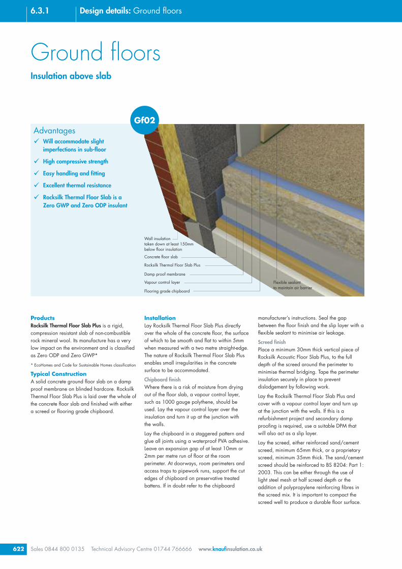
Screed finishPlace a minimum 30mm thick vertical piece ofRocksilk Acoustic Floor Slab Plus, to the fulldepth of the screed around the perimeter tominimise thermal bridging. Tape the perimeterinsulation securely in place to preventdislodgement by following work.
Lay the Rocksilk Thermal Floor Slab Plus andcover with a vapour control layer and turn upat the junction with the walls. If this is arefurbishment project and secondary dampproofing is required, use a suitable DPM thatwill also act as a slip layer.
Lay the screed, either reinforced sand/cementscreed, minimum 65mm thick, or a proprietaryscreed, minimum 35mm thick. The sand/cementscreed should be reinforced to BS 8204: Part 1:2003. This can be either through the use oflight steel mesh at half screed depth or theaddition of polypropylene reinforcing fibres inthe screed mix. It is important to compact thescreed well to produce a durable floor surface.
InstallationLay Rocksilk Thermal Floor Slab Plus directlyover the whole of the concrete floor, the surfaceof which to be smooth and flat to within 5mmwhen measured with a two metre straight-edge.The nature of Rocksilk Thermal Floor Slab Plusenables small irregularities in the concretesurface to be accommodated.
Chipboard finishWhere there is a risk of moisture from dryingout of the floor slab, a vapour control layer,such as 1000 gauge polythene, should beused. Lay the vapour control layer over theinsulation and turn it up at the junction withthe walls.
Lay the chipboard in a staggered pattern andglue all joints using a waterproof PVA adhesive.Leave an expansion gap of at least 10mm or2mm per metre run of floor at the roomperimeter. At doorways, room perimeters andaccess traps to pipework runs, support the cutedges of chipboard on preservative treatedbattens. If in doubt refer to the chipboard
ProductsRocksilk Thermal Floor Slab Plus is a rigid,compression resistant slab of non-combustiblerock mineral wool. Its manufacture has a verylow impact on the environment and is classifiedas Zero ODP and Zero GWP*
* EcoHomes and Code for Sustainable Homes classification
Typical ConstructionA solid concrete ground floor slab on a dampproof membrane on blinded hardcore. RocksilkThermal Floor Slab Plus is laid over the whole ofthe concrete floor slab and finished with eithera screed or flooring grade chipboard.
Advantages� Will accommodate slight
imperfections in sub-floor
� High compressive strength
� Easy handling and fitting
� Excellent thermal resistance
� Rocksilk Thermal Floor Slab is aZero GWP and Zero ODP insulant
Flooring grade chipboard
Vapour control layer
Damp proof membrane
Rocksilk Thermal Floor Slab Plus
Concrete floor slab
Wall insulationtaken down at least 150mmbelow floor insulation
Flexible sealantto maintain air barrier
Gf02

623
6.3.1Design details: Ground floors
Sales 0844 800 0135 Technical Advisory Centre 01744 766666 www.knaufinsulation.co.uk
Cavity wall insulation
Minimum 150mm overlapbetween wall and floor insulationto minimise thermal bridging
Flexible seal between skirtingboard and floor
Rocksilk Thermal Floor Slab Plus
Vapour control layer belowchipboard
Typical specificationInsulation below screedRocksilk Thermal Floor Slab Plus ......mmthick, to be close butted and placed over thewhole area of the floor. Rocksilk ThermalFloor Slab Plus, 30mm thick, to be cut andplaced to full depth of screed and floorinsulation at the floor perimeter.
The insulation to be overlaid with 1000gauge polythene, taken up and over theperimeter insulation. A 65mm thicksand/cement screed with wire mesh*/polypropylene reinforcing fibres* to be laidon top. (NHBC recommend a D49 fabricmesh for use in floating screeds).Alternatively install a proprietary liquidscreed (minimum thickness 35mm) laid inaccordance with manufacturers instructions.Floor finish as specified by the designer.
(* delete as appropriate)
Alternatively, refer to NBS clause:M10/40 or M10/290
Insulation below chipboardThe whole area of the concrete floor to becovered with Rocksilk Thermal Floor SlabPlus, …...mm thick. All slabs to be closebutted.
The insulation to be (overlaid with a vapourcontrol layer of 1000g polythene and)*
covered with 18mm t&g flooringgrade chipboard. (*delete asrequired)
Alternatively, refer to NBS clause:K11/25 or K11/225
PerformanceThermal performanceRocksilk Thermal Floor Slab Plus has a thermalconductivity of 0.038 W/mK.
Table 64 gives U-values for a range ofperimeter/area ratios.
Fire performanceRocksilk Thermal Floor Slab Plus is classified asEuroclass A1 to BS EN ISO 13501-1.
Table 64: U-values of concrete ground floor slab insulated below chipboard
U-values (W/m2K)Thickness Ratio of perimeter (m) to area (m2)
(mm) 0.1 0.2 0.3 0.4 0.5 0.6 0.7 0.8
Rocksilk Thermal Floor Slab Plus
210 (70 + 70 + 70) 0.09 0.11 0.12 0.13 0.14 0.14 0.14 0.15
170 (80 + 90) 0.10 0.13 0.14 0.15 0.16 0.17 0.17 0.17
150 (70 + 80) 0.10 0.14 0.15 0.17 0.17 0.18 0.19 0.19
130 (60 + 70) 0.11 0.15 0.17 0.18 0.19 0.20 0.21 0.21
100 0.12 0.17 0.20 0.21 0.23 0.24 0.25 0.25
90 0.12 0.18 0.21 0.23 0.24 0.25 0.26 0.27
80 0.13 0.19 0.22 0.24 0.26 0.27 0.28 0.29
70 0.13 0.20 0.23 0.26 0.28 0.29 0.30 0.31
60 0.14 0.21 0.25 0.28 0.30 0.32 0.33 0.34Note: The U-values have been calculated using BS EN ISO 13370: 1998 and assume a clay subsoil with a thermalconductivity of 1.50 W/mK.
Typical wall/floor junction
Thickness Compressive strengthmm Kpa
60, 70 60
80, 90, 100 70
Table 65: Rocksilk Thermal Floor Slab Pluscompressive strength

Advantages� Compression resistant, supporting
screed under high point loads
� Provides high thermal performancein limited insulation zone
� Structural and thermal solution
� Resistant to site damage
� Robust and can tolerate traffic fromfollowing trades without damageprior to floor finish being laid
Ground floorsInsulation above slab
Sales 0844 800 0135 Technical Advisory Centre 01744 766666 www.knaufinsulation.co.uk624
6.3.1 Design details: Ground floors
Polyfoam Floorboard
Lay the chipboard in a staggered pattern andglue all joints using a waterproof PVA adhesive.Leave an expansion gap of at least 10mm or2mm per metre run of floor at the roomperimeter. At doorways or access traps topipework runs, support the cut edges ofchipboard on preservative treated battens. If indoubt refer to the chipboard manufacturer’sinstructions. Seal between the wall and floor airbarrier with a flexible sealant, or seal the spacebetween the skirting board and the floor using aflexible sealant to minimise air leakage.
PerformanceThermal performanceThe thermal conductivities of PolyfoamFloorboard products are as follows:-
Standard - 0.029W/mK
Extra - 0.029 -0.034 W/mK
Super - 0.034 - 0.036W/mK
Table 66 gives U-values for a rangeof perimeter/area ratios.
Fire performanceWhen Polyfoam Floorboard is installed in afloor construction it will not contribute to thedevelopment stages of a fire.
Compression resistancePolyfoam Floorboard products are highlyresistant to compression – Table 67.
Screed finishPlace a minimum 25mm thick vertical piece ofPolyfoam Floorboard to the full depth of thescreed around the perimeter to minimise thermalbridging. Tape the perimeter insulation boardssecurely in place to prevent dislodgement byfollowing work.
Cover the Polyfoam Floorboard with aseparating/slip layer and turn up at the junctionwith the walls. if this is a refurbishment projectand secondary damp proofing is required, usea suitable DPM that will also act as a slip layer.
Lay the screed, either reinforced sand/cementscreed, minimum 65mm thick, or a proprietaryscreed, minimum 35mm thick. The sand/cementscreed should be reinforced to BS 8204: Part1:2003. This can be either through the use oflight steel mesh at half screed depth or theaddition of polypropylene reinforcing fibres inthe screed mix. It is important to compact thescreed well to produce a durable floor surface.
Chipboard finishWhere there is a risk of moisture from dryingout of the floor slab, a vapour control layer,such as 1000 gauge polythene, should beused. Lay the vapour control layer over theinsulation and turn it up at the junction withthe walls.
ProductsPolyfoam Floorboard is a range of 100% ozonefriendly extruded polystyrene rigid boardinsulation – it is lightweight yet has excellentstructural strength and long term effectiveness. Itis available in three grades:
Standard – domestic and light commercialloading
Extra – commercial, industrial flooring and coldstorage
Super – very high load commercial, industrialand cold storage floors
Typical construction
A solid concrete ground floor slab on a dampproof membrane on blinded hardcore.Polyfoam Floorboards laid over the whole of theconcrete floor slab and finished with eitherflooring grade chipboard or a floating screed,either sand/cement based, or a proprietaryflowing screed.
InstallationLay the Polyfoam Floorboard directly over thewhole of the concrete floor. The surface ofthe floor should be smooth and flat to within5mm when measured with a 2 metrestraight-edge. Irregularities greater than thismust be levelled out.
25mm Polyfoam Floorboardat screed perimeter
Gf03
Floating screed
Separating/slip layer
Damp proof membrane
Polyfoam Floorboard
Concrete floor slab
Wall insulationtaken down at least 150mmbelow floor insulation
Flexible sealantto maintain air barrier
625
6.3.1Design details: Ground floors
Sales 0844 800 0135 Technical Advisory Centre 01744 766666 www.knaufinsulation.co.uk
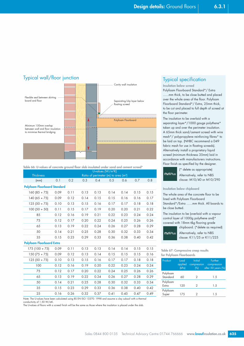
Table 66: U-values of concrete ground floor slab insulated under sand and cement screed*U-values (W/m2K)
Thickness Ratio of perimeter (m) to area (m2)(mm) 0.1 0.2 0.3 0.4 0.5 0.6 0.7 0.8
Polyfoam Floorboard Standard
160 (85 + 75) 0.09 0.11 0.13 0.13 0.14 0.14 0.15 0.15
140 (65 + 75) 0.09 0.12 0.14 0.15 0.15 0.16 0.16 0.17
125 (50 + 75) 0.10 0.13 0.15 0.16 0.17 0.17 0.18 0.18
100 (50 + 50) 0.11 0.15 0.17 0.19 0.20 0.20 0.21 0.22
85 0.12 0.16 0.19 0.21 0.22 0.23 0.24 0.24
75 0.12 0.17 0.20 0.22 0.24 0.25 0.26 0.26
65 0.13 0.19 0.22 0.24 0.26 0.27 0.28 0.29
50 0.14 0.21 0.25 0.28 0.30 0.32 0.33 0.34
35 0.15 0.23 0.29 0.33 0.36 0.38 0.40 0.42
Polyfoam Floorboard Extra
175 (100 + 75) 0.09 0.11 0.13 0.13 0.14 0.14 0.15 0.15
150 (75 + 75) 0.09 0.12 0.13 0.14 0.15 0.15 0.15 0.16
125 (50 + 75) 0.10 0.13 0.15 0.16 0.17 0.17 0.18 0.18
100 0.12 0.16 0.19 0.20 0.22 0.23 0.24 0.24
75 0.12 0.17 0.20 0.22 0.24 0.25 0.26 0.26
65 0.13 0.19 0.22 0.24 0.26 0.27 0.28 0.29
50 0.14 0.21 0.25 0.28 0.30 0.32 0.33 0.34
35 0.15 0.23 0.29 0.33 0.36 0.38 0.40 0.42
25 0.16 0.26 0.32 0.37 0.41 0.45 0.47 0.49Note: The U-values have been calculated using BS EN ISO 13370: 1998 and assume a clay subsoil with a thermalconductivity of 1.50 W/mK.The U-values of floors with a screed finish will be the same as those where the insulation is placed under the slab.
Cavity wall insulation
Minimum 150mm overlapbetween wall and floor insulationto minimise thermal bridging
Flexible seal between skirtingboard and floor
Polyfoam Floorboard
Separating/slip layer belowfloating screed
Typical specificationInsulation below screedPolyfoam Floorboard Standard*/ Extra......mm thick, to be close butted and placedover the whole area of the floor. PolyfoamFloorboard Standard*/ Extra, 25mm thick,to be cut and placed to full depth of screed atthe floor perimeter.
The insulation to be overlaid with aseparating layer*/1000 gauge polythene*taken up and over the perimeter insulation.A 65mm thick sand/cement screed with wiremesh*/ polypropylene reinforcing fibres* tobe laid on top. (NHBC recommend a D49fabric mesh for use in floating screeds).Alternatively install a proprietary liquidscreed (minimum thickness 35mm) laid inaccordance with manufacturers instructions.Floor finish as specified by the designer.
(* delete as appropriate)
Alternatively, refer to NBSclause: M10/40 or M10/290
Insulation below chipboard
The whole area of the concrete floor to belined with Polyfoam FloorboardStandard*/Extra …...mm thick. All boards tobe close butted.
The insulation to be (overlaid with a vapourcontrol layer of 1000g polythene and)*covered with 18mm t&g flooring grade
chipboard. (*delete as required)
Alternatively, refer to NBSclause: K11/25 or K11/225
Typical wall/floor junction
Product Load Initial Furtherapplied compression compression
(kPa) (%) after 50 years (%)
PolyfoamStandard 60 2 1.5
PolyfoamExtra 120 2 1.5
PolyfoamSuper 175 2 1.5
Table 67: Compressive creep resultsfor Polyfoam Floorboards
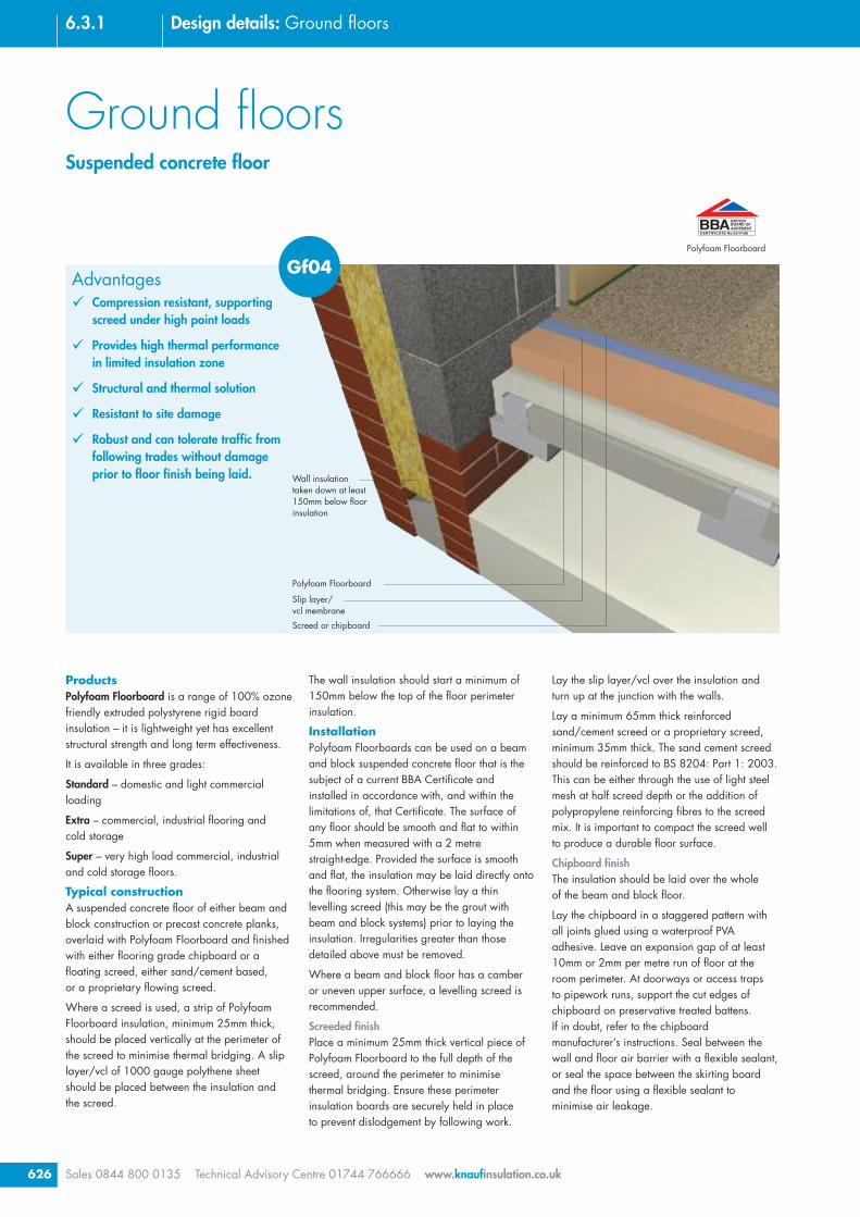
Ground floorsSuspended concrete floor
Sales 0844 800 0135 Technical Advisory Centre 01744 766666 www.knaufinsulation.co.uk626
6.3.1 Design details: Ground floors
Polyfoam Floorboard
Lay the slip layer/vcl over the insulation andturn up at the junction with the walls.
Lay a minimum 65mm thick reinforcedsand/cement screed or a proprietary screed,minimum 35mm thick. The sand cement screedshould be reinforced to BS 8204: Part 1: 2003.This can be either through the use of light steelmesh at half screed depth or the addition ofpolypropylene reinforcing fibres to the screedmix. It is important to compact the screed wellto produce a durable floor surface.
Chipboard finishThe insulation should be laid over the wholeof the beam and block floor.
Lay the chipboard in a staggered pattern withall joints glued using a waterproof PVAadhesive. Leave an expansion gap of at least10mm or 2mm per metre run of floor at theroom perimeter. At doorways or access trapsto pipework runs, support the cut edges ofchipboard on preservative treated battens.If in doubt, refer to the chipboardmanufacturer’s instructions. Seal between thewall and floor air barrier with a flexible sealant,or seal the space between the skirting boardand the floor using a flexible sealant tominimise air leakage.
The wall insulation should start a minimum of150mm below the top of the floor perimeterinsulation.
InstallationPolyfoam Floorboards can be used on a beamand block suspended concrete floor that is thesubject of a current BBA Certificate andinstalled in accordance with, and within thelimitations of, that Certificate. The surface ofany floor should be smooth and flat to within5mm when measured with a 2 metrestraight-edge. Provided the surface is smoothand flat, the insulation may be laid directly ontothe flooring system. Otherwise lay a thinlevelling screed (this may be the grout withbeam and block systems) prior to laying theinsulation. Irregularities greater than thosedetailed above must be removed.
Where a beam and block floor has a camberor uneven upper surface, a levelling screed isrecommended.
Screeded finishPlace a minimum 25mm thick vertical piece ofPolyfoam Floorboard to the full depth of thescreed, around the perimeter to minimisethermal bridging. Ensure these perimeterinsulation boards are securely held in placeto prevent dislodgement by following work.
ProductsPolyfoam Floorboard is a range of 100% ozonefriendly extruded polystyrene rigid boardinsulation – it is lightweight yet has excellentstructural strength and long term effectiveness.
It is available in three grades:
Standard – domestic and light commercialloading
Extra – commercial, industrial flooring andcold storage
Super – very high load commercial, industrialand cold storage floors.
Typical constructionA suspended concrete floor of either beam andblock construction or precast concrete planks,overlaid with Polyfoam Floorboard and finishedwith either flooring grade chipboard or afloating screed, either sand/cement based,or a proprietary flowing screed.
Where a screed is used, a strip of PolyfoamFloorboard insulation, minimum 25mm thick,should be placed vertically at the perimeter ofthe screed to minimise thermal bridging. A sliplayer/vcl of 1000 gauge polythene sheetshould be placed between the insulation andthe screed.
Advantages� Compression resistant, supporting
screed under high point loads
� Provides high thermal performancein limited insulation zone
� Structural and thermal solution
� Resistant to site damage
� Robust and can tolerate traffic fromfollowing trades without damageprior to floor finish being laid.
Screed or chipboard
Slip layer/vcl membrane
Polyfoam Floorboard
Wall insulationtaken down at least150mm below floorinsulation
Gf04

627
6.3.1Design details: Ground floors
Sales 0844 800 0135 Technical Advisory Centre 01744 766666 www.knaufinsulation.co.uk
Cavity wall insulation
Minimum 150mm overlapbetween wall and floor insulationto minimise thermal bridging
Flexible seal between skirtingboard and floor
Polyfoam Floorboard
Vapour control layer belowchipboard
Levelling screed (where required)
Typical specificationInsulation below screedPolyfoam Floorboard Standard*/Extra*......mm thick, to be close butted and placedover the whole area of the floor. PolyfoamFloorboard, ......mm thick, to be cut andplaced to full depth of screed at the floorperimeter.
The insulation to be overlaid with 1000gauge polythene, taken up and over theperimeter insulation. A 65mm thicksand/cement screed with wire mesh*/polypropylene reinforcing fibres* to be laidon top. (NHBC recommend a D49 fabricmesh for use in floating screeds).Alternatively install a proprietary liquidscreed (minimum thickness 35mm) laid inaccordance with manufacturers instructions.Floor finish as specified by the designer.(* delete as appropriate)
Alternatively, refer to NBSclause: M10/40 or M10/290
Insulation below chipboardThe whole area of the concrete floor to beoverlaid with Polyfoam FloorboardStandard*/Extra, …...mm thick. All boardsto be close butted.
The insulation to be (overlaid with a vapourcontrol layer of 1000g polythene and)*covered with 18mm t&g flooring gradechipboard. (*delete as required)
Alternatively, refer to NBSclause: K11/25 or K11/225
Performance
Thermal performanceThe thermal conductivities of PolyfoamFloorboard products are as follows:
Floorboard – 0.029W/mK
Extra – 0.029 - 0.034 W/mK
Super – 0.034 - 0.036W/mK
Table gives 68 U-values for a range ofperimeter/area ratios.
Table 68: U-values of beam and block ground floor with chipboard deck
U-values (W/m2K)Thickness Ratio of perimeter (m) to area (m2)
(mm) 0.1 0.2 0.3 0.4 0.5 0.6 0.7 0.8
Polyfoam Floorboard Standard
160 (85+75) 0.10 0.12 0.13 0.14 0.14 0.14 0.15 0.15
140 (65+75) 0.11 0.13 0.14 0.15 0.16 0.16 0.16 0.16
125 (50+75) 0.12 0.14 0.16 0.16 0.17 0.17 0.18 0.18
100 (50+50) 0.13 0.16 0.18 0.19 0.20 0.20 0.21 0.21
85 0.14 0.18 0.20 0.21 0.22 0.23 0.23 0.24
75 0.14 0.19 0.21 0.23 0.24 0.25 0.25 0.26
65 0.15 0.20 0.23 0.25 0.26 0.27 0.28 0.29
50 0.16 0.23 0.26 0.29 0.30 0.32 0.33 0.34
35 0.18 0.26 0.30 0.33 0.36 0.38 0.39 0.40
25 0.19 0.28 0.34 0.38 0.41 0.43 0.45 0.47Note: The U-values have been calculated using BS EN ISO 13370: 1998 and assume a clay subsoil with a thermalconductivity of 1.50 W/mK.
The thermal conductivity of concrete blocks – 1.22 W/mK.
For project specific calculations contact our Technical Advisory Centre on 01744 766666.
Typical wall/floor junction
Fire performanceWhen Polyfoam Floorboard is installed in afloor construction it will not contribute to thedevelopment stages of a fire.
Compression resistancePolyfoam Floorboards are highly resistant tocompression – see Table 69.
Product Load Initial Furtherapplied compression compression
(kPa) (%) after 50 years (%)
PolyfoamStandard 60 2 1.5
PolyfoamExtra 120 2 1.5
PolyfoamSuper 175 2 1.5
Table 69: Compressive creep resultsfor Polyfoam Floorboards

Screed or chipboard
Vapour control layer
Rocksilk Thermal Floor Slab Plus
Ventilated sub floor
Wall insulationtaken down at least150mm below floor insulation
Ground floorsSuspended concrete floor
Sales 0844 800 0135 Technical Advisory Centre 01744 766666 www.knaufinsulation.co.uk628
6.3.1 Design details: Ground floors
Chipboard finishThe insulation should be laid over the whole ofthe concrete floor.
Lay the chipboard in a staggered pattern withall joints glued using a waterproof PVAadhesive. Leave an expansion gap of at least10mm or 2mm per metre run of floor at theroom perimeter. At doorways, room perimetersand access traps to pipework, runs support thecut edges of chipboard on preservative treatedbattens. If in doubt, refer to the chipboardmanufacturer’s instructions. Seal between thewall and floor air barrier with a flexible sealant,or seal the space between the skirting boardand the floor using a flexible sealant tominimise air leakage.
Performance
Thermal performanceRocksilk Thermal Floor Slab Plus has a thermalconductivity of 0.038 W/mK.
Table 71 gives U-values for a range ofperimeter/area ratios.
Fire performanceRocksilk Thermal Floor Slab Plus is classified asEuroclass A1 to BS EN ISO 13501-1.
InstallationRocksilk Thermal Floor Slab Plus may be laiddirectly onto the flooring system. The surface ofany floor should be smooth and flat to within5mm when measured with a 2 metrestraight-edge. Irregularities greater than thosedetailed above must be removed.
Screed finishPlace a minimum 30mm thick vertical piece ofRocksilk Thermal Floor Slab Plus to the full depthof the screed, around the perimeter to minimisethermal bridging. Ensure the perimeterinsulation is securely held in place to preventdislodgement by following work.
Lay the vcl/slip layer over the insulation andturn up at the junction with the walls.
Lay a minimum 65mm thick reinforcedsand/cement screed. The screed should bereinforced to BS 8204: Part 1: 2003. This canbe either through the use of light steel mesh athalf screed depth or the addition ofpolypropylene reinforcing fibres to the screedmix. It is important to compact the screed wellto produce a durable floor surface.
ProductsRocksilk Thermal Floor Slab Plus is a rigid,compression resistant slab of non-combustiblerock mineral wool. Its manufacture has a verylow impact on the environment and is classifiedas Zero ODP and Zero GWP*
* EcoHomes and Code for Sustainable Homes classification
Typical ConstructionA suspended concrete floor of either beam andblock construction or precast concrete planks,overlaid with Rocksilk Thermal Floor Slab Plusand finished with either flooring gradechipboard or a floating screed, eithersand/cement based, or a proprietary flowingscreed.
Where a screed is used, a strip of RocksilkThermal Floor Slab Plus, minimum 30mm thick,should be placed vertically at the perimeter ofthe screed to minimise thermal bridging.A vapour control layer/slip layer of 1000gauge polythene sheet should be placedbetween the insulation and the screed.
The wall insulation should start a minimum of150mm below the top of the floor perimeterinsulation.
Advantages� Will accommodate slight
imperfections in sub-floor
� High compressive strength
� Easy handling and fitting
� Excellent thermal resistance
� Rocksilk Thermal Floor Slab is aZero GWP and Zero ODP insulant
Gf05

629
6.3.1Design details: Ground floors
Sales 0844 800 0135 Technical Advisory Centre 01744 766666 www.knaufinsulation.co.uk
Cavity wall insulation
Minimum 150mm overlapbetween wall and floor insulationto minimise thermal bridging
Flexible seal between skirtingboard and floor
Rocksilk Thermal FloorSlab Plus
Vapour control/slip layer belowscreed or chipboard
Levelling screed where required
Typical specificationInsulation below screedRocksilk Thermal Floor Slab Plus ......mmthick, to be close butted and placed over thewhole area of the floor. Rocksilk ThermalFloor Slab Plus, 30mm thick, to be cut andplaced to full depth of screed at the floorperimeter.
The insulation to be overlaid with 1000gauge polythene, taken up and over theperimeter insulation. A 65mm thicksand/cement screed with wire mesh*/polypropylene reinforcing fibres* to be laidon top. (NHBC recommend a D49 fabricmesh for use in floating screeds).Alternatively install a proprietary liquidscreed (minimum thickness 35mm) laid inaccordance with manufacturers instructions.Floor finish as specified by the designer.
(* delete as appropriate)
Alternatively, refer to NBSclause: M10/40 or M10/290
Insulation below chipboardThe whole area of the concrete floor to belined with Rocksilk Thermal Floor Slab Plus,…...mm thick. All slabs to be close butted.
The insulation to be (overlaid with a vapourcontrol layer of 1000g polythene and)*covered with 18mm t&g flooring grade
chipboard. (*delete as required)
Alternatively, refer to NBSclause: K11/25 or K11/225
Table 71: U-values of beam and block ground floor with chipboard
U-values (W/m2K)Thickness Ratio of perimeter (m) to area (m2)
(mm) 0.1 0.2 0.3 0.4 0.5 0.6 0.7 0.8Rocksilk Thermal Floor Slab Plus
210 (70+70+70) 0.10 0.12 0.13 0.14 0.14 0.14 0.15 0.15
170 (80+90) 0.11 0.14 0.15 0.16 0.17 0.17 0.17 0.17
150 (70+80) 0.12 0.15 0.17 0.17 0.18 0.19 0.19 0.19
130 (60+70) 0.13 0.16 0.18 0.19 0.20 0.21 0.21 0.21
100 0.14 0.19 0.21 0.23 0.24 0.25 0.25 0.26
90 0.15 0.20 0.22 0.24 0.25 0.26 0.27 0.28
80 0.15 0.21 0.24 0.26 0.27 0.28 0.29 0.30
70 0.16 0.22 0.25 0.28 0.29 0.30 0.31 0.32
60 0.17 0.23 0.27 0.30 0.32 0.33 0.34 0.35
Note: The U-values have been calculated using BS EN ISO 13370: 1998 and assume a 0.16 W/mK aircrete blockbetween concrete beams.
Typical wall/floor junction
Thickness Compressive strengthmm Kpa
60, 70 60
80, 90, 100 70
Table 70: Rocksilk Thermal Floor Slab Pluscompressive strength
Flexible seal
Crown Loft Roll 44/40 or Rocksilk Flexible Slab
Support netting
Ventilated floor void
Wall insulationtaken down at least200mm below floor insulation
Chipboard floordeck
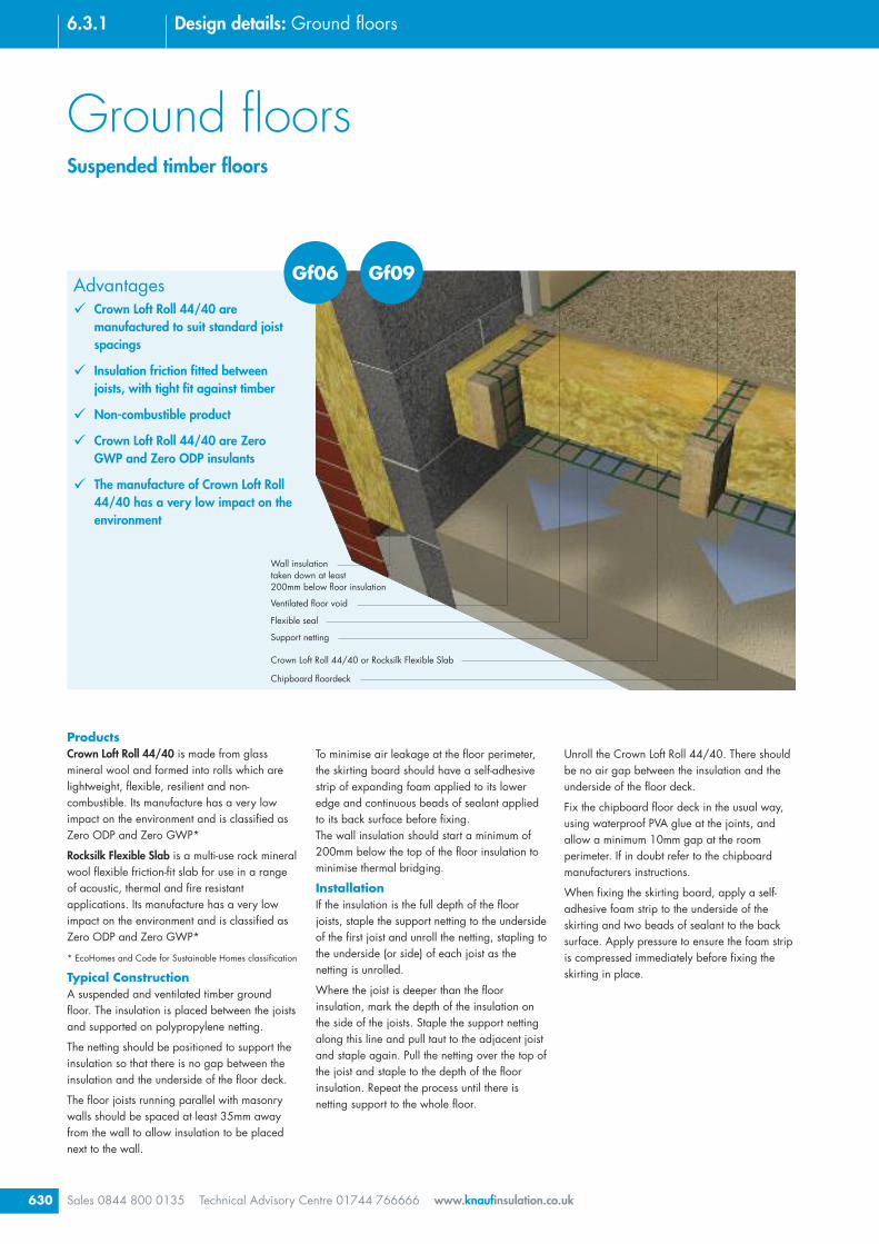
Ground floorsSuspended timber floors
Sales 0844 800 0135 Technical Advisory Centre 01744 766666 www.knaufinsulation.co.uk630
6.3.1 Design details: Ground floors
Unroll the Crown Loft Roll 44/40. There shouldbe no air gap between the insulation and theunderside of the floor deck.
Fix the chipboard floor deck in the usual way,using waterproof PVA glue at the joints, andallow a minimum 10mm gap at the roomperimeter. If in doubt refer to the chipboardmanufacturers instructions.
When fixing the skirting board, apply a self-adhesive foam strip to the underside of theskirting and two beads of sealant to the backsurface. Apply pressure to ensure the foam stripis compressed immediately before fixing theskirting in place.
To minimise air leakage at the floor perimeter,the skirting board should have a self-adhesivestrip of expanding foam applied to its loweredge and continuous beads of sealant appliedto its back surface before fixing.The wall insulation should start a minimum of200mm below the top of the floor insulation tominimise thermal bridging.
InstallationIf the insulation is the full depth of the floorjoists, staple the support netting to the undersideof the first joist and unroll the netting, stapling tothe underside (or side) of each joist as thenetting is unrolled.
Where the joist is deeper than the floorinsulation, mark the depth of the insulation onthe side of the joists. Staple the support nettingalong this line and pull taut to the adjacent joistand staple again. Pull the netting over the top ofthe joist and staple to the depth of the floorinsulation. Repeat the process until there isnetting support to the whole floor.
ProductsCrown Loft Roll 44/40 is made from glassmineral wool and formed into rolls which arelightweight, flexible, resilient and non-combustible. Its manufacture has a very lowimpact on the environment and is classified asZero ODP and Zero GWP*
Rocksilk Flexible Slab is a multi-use rock mineralwool flexible friction-fit slab for use in a rangeof acoustic, thermal and fire resistantapplications. Its manufacture has a very lowimpact on the environment and is classified asZero ODP and Zero GWP*
* EcoHomes and Code for Sustainable Homes classification
Typical ConstructionA suspended and ventilated timber groundfloor. The insulation is placed between the joistsand supported on polypropylene netting.
The netting should be positioned to support theinsulation so that there is no gap between theinsulation and the underside of the floor deck.
The floor joists running parallel with masonrywalls should be spaced at least 35mm awayfrom the wall to allow insulation to be placednext to the wall.
Advantages� Crown Loft Roll 44/40 are
manufactured to suit standard joistspacings
� Insulation friction fitted betweenjoists, with tight fit against timber
� Non-combustible product
� Crown Loft Roll 44/40 are ZeroGWP and Zero ODP insulants
� The manufacture of Crown Loft Roll44/40 has a very low impact on theenvironment
Gf06 Gf09
631
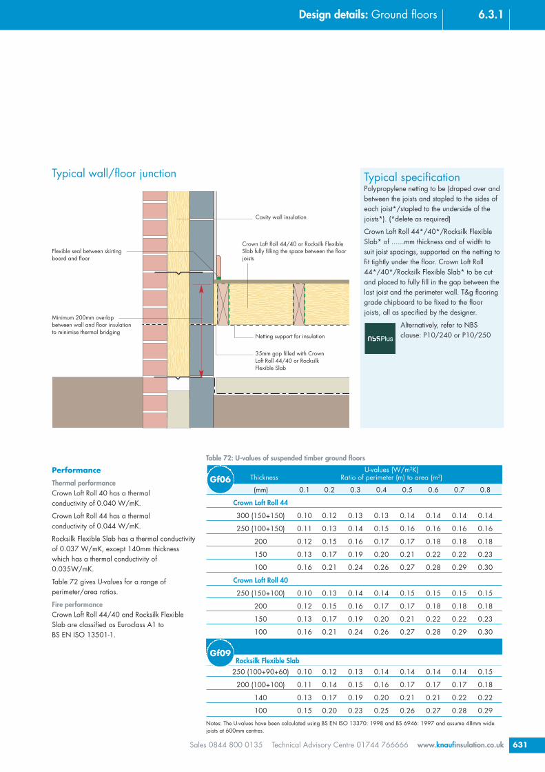
6.3.1Design details: Ground floors
Sales 0844 800 0135 Technical Advisory Centre 01744 766666 www.knaufinsulation.co.uk
Cavity wall insulation
Flexible seal between skirtingboard and floor
Crown Loft Roll 44/40 or Rocksilk FlexibleSlab fully filling the space between the floorjoists
Netting support for insulation
35mm gap filled with CrownLoft Roll 44/40 or RocksilkFlexible Slab
Typical specificationPolypropylene netting to be (draped over andbetween the joists and stapled to the sides ofeach joist*/stapled to the underside of thejoists*). (*delete as required)
Crown Loft Roll 44*/40*/Rocksilk FlexibleSlab* of ......mm thickness and of width tosuit joist spacings, supported on the netting tofit tightly under the floor. Crown Loft Roll44*/40*/Rocksilk Flexible Slab* to be cutand placed to fully fill in the gap between thelast joist and the perimeter wall. T&g flooringgrade chipboard to be fixed to the floorjoists, all as specified by the designer.
Alternatively, refer to NBSclause: P10/240 or P10/250
Performance
Thermal performanceCrown Loft Roll 40 has a thermalconductivity of 0.040 W/mK.
Crown Loft Roll 44 has a thermalconductivity of 0.044 W/mK.
Rocksilk Flexible Slab has a thermal conductivityof 0.037 W/mK, except 140mm thicknesswhich has a thermal conductivity of0.035W/mK.
Table 72 gives U-values for a range ofperimeter/area ratios.
Fire performanceCrown Loft Roll 44/40 and Rocksilk FlexibleSlab are classified as Euroclass A1 toBS EN ISO 13501-1.
Minimum 200mm overlapbetween wall and floor insulationto minimise thermal bridging
Typical wall/floor junction
Table 72: U-values of suspended timber ground floors
U-values (W/m2K)Thickness Ratio of perimeter (m) to area (m2)
(mm) 0.1 0.2 0.3 0.4 0.5 0.6 0.7 0.8
Crown Loft Roll 44
300 (150+150) 0.10 0.12 0.13 0.13 0.14 0.14 0.14 0.14
250 (100+150) 0.11 0.13 0.14 0.15 0.16 0.16 0.16 0.16
200 0.12 0.15 0.16 0.17 0.17 0.18 0.18 0.18
150 0.13 0.17 0.19 0.20 0.21 0.22 0.22 0.23
100 0.16 0.21 0.24 0.26 0.27 0.28 0.29 0.30
Crown Loft Roll 40
250 (150+100) 0.10 0.13 0.14 0.14 0.15 0.15 0.15 0.15
200 0.12 0.15 0.16 0.17 0.17 0.18 0.18 0.18
150 0.13 0.17 0.19 0.20 0.21 0.22 0.22 0.23
100 0.16 0.21 0.24 0.26 0.27 0.28 0.29 0.30
Rocksilk Flexible Slab250 (100+90+60) 0.10 0.12 0.13 0.14 0.14 0.14 0.14 0.15
200 (100+100) 0.11 0.14 0.15 0.16 0.17 0.17 0.17 0.18
140 0.13 0.17 0.19 0.20 0.21 0.21 0.22 0.22
100 0.15 0.20 0.23 0.25 0.26 0.27 0.28 0.29
Notes: The U-values have been calculated using BS EN ISO 13370: 1998 and BS 6946: 1997 and assume 48mm widejoists at 600mm centres.
Gf06
Gf09

Floating liquid or traditional screed
Osma Underfloor Heating system board
Damp proof membrane
Concrete floor slab
Wall insulationtaken down at least150mm below floor insulation
Ground floorsUnderfloor heating – Osma Underfloor Heating System
Sales 0844 800 0135 Technical Advisory Centre 01744 766666 www.knaufinsulation.co.uk632
6.3.1 Design details: Ground floors
return boards at ends and walls. Continue untilthe entire floor area to be insulated and heatedis covered with Polyfoam insulation boards.
Starting from the manifold, lay the single run ofpipe, pushing it firmly into the holding groovesin the insulation boards. Following the patternof the pre-channelled insulation until the pipereturns to the manifold system, cut and connect.Test the system before finishing the floor.
Lay the liquid or traditional cement/sand screedto the specified depth. Polyfoam Floorboard issuitable for both liquid screeds and a traditionalcement/sand screed.
Performance
Thermal performanceThis system utilises Polyfoam FloorboardStandard which has a thermal conductivity of0.029 W/mK.
Table 74 gives U-values for a rangeof perimeter/area ratios.
Fire performanceWhen Pre-channelled Polyfoam Floorboard isinstalled below a screed it will not contribute tothe development stages of a fire.
Polyfoam Floorboard laid over the whole of theconcrete floor slab, the heating pipes installedand covered with either a liquid or traditionalscreed finish.
Using liquid screeds, the depth of the screedcan be kept to a minimum to provide a fastacting and highly efficient heating system
The pre-channelled Polyfoam Floorboard panelsare rigid sheets of extruded polystyreneinsulation that have channels cut into the topsurface, into which the heating pipe is pressed.At intervals along the length of these channels,the channel is widened to form pockets that areslightly deeper than the diameter of the pipe.The widened pockets have been designed toencourage the screed to encase the pipe inorder to achieve efficient heat transfer into thescreed.
InstallationThe concrete slab is cast in the normal manner,with the damp proof membrane below the slab.Starting from the corner furthest from themanifold outlet connection, lay the pre-channelled insulation boards, ensuring thatgrooves are in line. Use prepared rounded
ProductsPolyfoam Floorboard Standard is a 100%ozone friendly, extruded polystyrene, rigidboard insulation - it is lightweight, yet hasexcellent structural strength and long termeffectiveness.
Osma Underfloor Heating is a partner companyof Knauf Insulation and offers a wide range ofunderfloor heating solutions – each systemoffers the excellent energy saving, clean designlines and high performance associated withunderfloor heating systems.
The solution on this page utilises the benefits ofPolyfoam extruded polystyrene (strength,versatility, ease of cutting and ease of handling)to produce an unrivalled range of underfloorheating systems for any floor construction inboth new build and refurbishment projects.
The panels are machined using the latest CNC(Computer Numerical Control) technology toensure the pipes are installed accurately.
Typical constructionA solid concrete ground floor slab on a dampproof membrane on blinded hardcore or asuspended concrete floor. Pre-channelled
AdvantagesThe decision to use an underfloor heatingsystem will be taken on its merits as aheating strategy. The advantages listedbelow relate to the use of this systemagainst other installation methods.
� Insulation and heating is providedby one complete system
� High quality installation isachievable and repeatable withpipes installed at the correct centres
� Heating pipes are carried within theinsulation allowing a thinner layerof screed
� Prevents warm spots where flowand return pipes are concentrated
Gf07

633
6.3.1Design details: Ground floors
Sales 0844 800 0135 Technical Advisory Centre 01744 766666 www.knaufinsulation.co.uk
Typical specificationPre-channelled Polyfoam FloorboardStandard ......mm thick, to be closely buttedand placed over the whole area of the floor.Polyfoam Floorboard, at least 25mm thick, tobe cut and placed to full depth of screed atthe floor perimeter.
A single run of pipe (by Osma) to be pushedfirmly into the holding grooves in theinsulation boards following the pattern of thepre-channelled insulation until the pipereturns to the manifold system. The pipes tobe tested before the screed is laid.
A 65mm thick sand/cement screed with wiremesh*/ polypropylene reinforcing fibres* tobe laid on top. (NHBC recommend a D49fabric mesh for use in floating screeds).Alternatively install a proprietary liquidscreed (minimum thickness 35mm) laid inaccordance with manufacturers instructions.Floor finish as specified by the designer.(* delete as appropriate)
Alternatively, refer to NBSclause: M10/40 or M10/290
Compression resistancePre-channelled Polyfoam Floorboard is highlyresistant to compression – see table 73.
Table 74: U-values of concrete ground floor slab insulated with pre-channelled PolyfoamFloorboard below a screed
U-values (W/m2K)Thickness Ratio of perimeter (m) to area (m2)
mm 0.1 0.2 0.3 0.4 0.5 0.6 0.7 0.8
Insulation Below Screed – Pre-channelled Polyfoam Floorboard Standard160 (75+65*) 0.09 0.11 0.13 0.13 0.14 0.14 0.15 0.15140 (75+65*) 0.09 0.12 0.14 0.15 0.15 0.16 0.16 0.17125 (50+75*) 0.10 0.13 0.15 0.16 0.17 0.17 0.18 0.18100 (50+50*) 0.11 0.15 0.17 0.19 0.20 0.20 0.21 0.2285 (35+50*) 0.12 0.16 0.19 0.21 0.22 0.23 0.24 0.24
75 0.12 0.17 0.20 0.22 0.24 0.25 0.26 0.2650 0.14 0.21 0.25 0.28 0.30 0.32 0.33 0.3435 0.15 0.23 0.29 0.33 0.36 0.38 0.40 0.42
Beam and Block – Pre-channelled Polyfoam Floorboard Standard160 (75+65*) 0.10 0.12 0.13 0.14 0.14 0.14 0.15 0.15140 (75+65*) 0.11 0.13 0.14 0.15 0.16 0.16 0.16 0.16125 (50+75*) 0.12 0.14 0.16 0.16 0.17 0.17 0.18 0.18100 (50+50*) 0.13 0.16 0.18 0.19 0.20 0.20 0.21 0.2185 (35+50*) 0.14 0.18 0.20 0.21 0.22 0.23 0.23 0.24
75 0.14 0.19 0.21 0.23 0.24 0.25 0.25 0.2650 0.16 0.23 0.26 0.29 0.30 0.32 0.33 0.3335 0.18 0.26 0.30 0.33 0.36 0.38 0.39 0.40
Note: The U-values have been calculated using BS EN ISO 13370: 1998 and assume a clay subsoil with a thermalconductivity of 1.50 W/mK.For project specific calculations contact our Technical Advisory Centre on 01744 766666.*Polyfoam Floorboard Standard laid underneath
Typical wall/floor junction
Cavity wall insulation
Minimum 150mm overlapbetween wall and floor insulationto minimise thermal bridging
Damp proofmembrane
Flexible seal between skirtingboard and floor
Osma Underfloor Heating system board
Floating screed
Concrete floor slab
Continuous ribbon ofplasterboard adhesive
Product Load Initial Furtherapplied compression compression
(kPa) (%) after 50 years (%)
PolyfoamStandard 60 2 1.5
PolyfoamExtra 120 2 1.5
PolyfoamSuper 175 2 1.5
Table 73: Compressive creep resultsfor Polyfoam Floorboards

Ground floorsUnderfloor heating – Polyfoam Floorboard Standard
Sales 0844 800 0135 Technical Advisory Centre 01744 766666 www.knaufinsulation.co.uk634
6.3.1 Design details: Ground floors
Polyfoam Floorboard
Performance
Thermal performanceThe thermal conductivities of Polyfoam productsare as follows:-
Standard – 0.029W/mK
Extra – 0.029-0.034 W/mK
Table 76 gives U-values for a rangeof perimeter/area ratios for both solid andsuspended beam and block ground floors.
Fire performanceWhen Polyfoam Floorboards are installedbelow a screed they will not contribute to thedevelopment stages of a fire.
Compression resistancePolyfoam Floorboards are highly resistant tocompression – see table 75.
InstallationThe concrete slab is cast in the normal manner,with the damp proof membrane below theslab. Starting from the corner furthest from themanifold outlet connection lay the PolyfoamFloorboards, ensuring the entire floor area iscovered.
Starting from the manifold, lay the single runof pipe, fixing it firmly into the insulationboards. Ensure the pipes and pipe returns areinstalled at the required centres and arereturned to the manifold system. Test the systembefore finishing the floor.
Lay the liquid or traditional cement/sand screedto the specified depth. Polyfoam Floorboardsare suitable for use with both liquid screeds anda traditional cement/sand screed.
Alternatively, the UFH system is installed withinthe concrete floor slab which is laid on top ofPolyfoam Floorboards.
ProductsPolyfoam Floorboard Standard panels are rigidsheets of extruded polystyrene insulation for usewith an underfloor heating system, using eitherclips, staples or a rail system, making it an idealsolution for use in a wide variety of floors.
Typical constructionA solid concrete ground floor slab on a dampproof membrane on blinded hardcore.Polyfoam Standard laid over the whole ofthe concrete floor slab, the heating pipes, usingclips, staples or rails, installed and coveredwith either a liquid or traditional screed finish.
Advantages� Insulation and heating is provided
by one complete system
� Available in two compressivestrengths, allowing underfloorheating to be used in buildingswhere a high load will be exertedon the floor
� Holds the clips extremely well,making installation quickerand easier
Gf08
Concrete floor slab
Damp proof membrane
Sand blinding
Wall insulationtaken down at least 150mmbelow floor insulation
Polyfoam Floorboardbefore application ofscreed
Product Load Initial Furtherapplied compression compression
(kPa) (%) after 50 years (%)
Polyfoam Standard
60 2 1.5
Polyfoam Extra
120 2 1.5
Table 75: Compressive creep resultsfor Polyfoam Floorboards

635
6.3.1Design details: Ground floors
Sales 0844 800 0135 Technical Advisory Centre 01744 766666 www.knaufinsulation.co.uk
Cavity wall insulation
Minimum 150mm overlapbetween wall and floor insulationto minimise thermal bridging
Flexible seal betweenskirting board and floor
Polyfoam Standard
Floating screed, with embeddedheating pipes
Concrete floor slab
25mm Polyfoam Standard
Typical specificationPolyfoam Floorboard Standard*/ Extra*......mm thick, to be closely butted andplaced over the whole area of the floor.Polyfoam Floorboard, at least 25mm thick, tobe cut and placed to full depth of screed atthe floor perimeter.
A single run of pipe to be fixed firmly into theinsulation boards and returned to themanifold system. The pipes to be testedbefore the screed is laid.
A 65mm thick sand/cement screed with wiremesh*/ polypropylene reinforcing fibres* tobe laid on top. (NHBC recommend a D49fabric mesh for use in floating screeds).Alternatively install a proprietary liquidscreed (minimum thickness 35mm) laid inaccordance with manufacturers instructions.Floor finish as specified by the designer.
(* delete as appropriate)
Alternatively, refer to NBSclause: M10/40 or M10/290
Typical wall/floor junction
Continuous ribbon ofplasterboard adhesive
Table 76: U-values of concrete ground floor slab insulated below a screed
U-values (W/m2K)Thickness Ratio of perimeter (m) to area (m2)
mm 0.1 0.2 0.3 0.4 0.5 0.6 0.7 0.8Polyfoam Floorboards
160 (75+65*) 0.09 0.11 0.13 0.13 0.14 0.14 0.15 0.15140 (75+65*) 0.09 0.12 0.14 0.15 0.15 0.16 0.16 0.17125 (50+75*) 0.10 0.13 0.15 0.16 0.17 0.17 0.18 0.18100 (50+50*) 0.11 0.15 0.17 0.19 0.20 0.20 0.21 0.2285 (35+50*) 0.12 0.16 0.19 0.21 0.22 0.23 0.24 0.24
75 0.12 0.17 0.20 0.22 0.24 0.25 0.26 0.2665 0.13 0.19 0.22 0.24 0.26 0.27 0.28 0.2950 0.14 0.21 0.25 0.28 0.30 0.32 0.33 0.3435 0.15 0.23 0.29 0.33 0.36 0.38 0.40 0.42
Beam and Block – Polyfoam Floorboards160 (75+65*) 0.10 0.12 0.13 0.14 0.14 0.14 0.15 0.15140 (75+65*) 0.11 0.13 0.14 0.15 0.16 0.16 0.16 0.16125 (50+75*) 0.12 0.14 0.16 0.16 0.17 0.17 0.18 0.18100 (50+50*) 0.13 0.16 0.18 0.19 0.20 0.20 0.21 0.2185 (35+50*) 0.14 0.18 0.20 0.21 0.22 0.23 0.23 0.24
75 0.14 0.19 0.21 0.23 0.24 0.25 0.25 0.2665 0.15 0.20 0.23 0.25 0.26 0.27 0.28 0.2950 0.16 0.23 0.26 0.29 0.30 0.32 0.33 0.3335 0.18 0.26 0.30 0.33 0.36 0.38 0.39 0.40
Note: The U-values have been calculated using BS EN ISO 13370: 1998 and assume a clay subsoil with a thermalconductivity of 1.50 W/mK.For project specific calculations contact our Technical Advisory Centre on 01744 766666.*Polyfoam Floorboard Standard laid underneath

www.knaufinsulation.co.uk
www.thinkinsulation.com
Knauf Insulation Ltd.PO Box 10Stafford RoadSt HelensMerseysideWA10 3NS
Customer Service (Sales)Tel: 0844 800 0135Fax: 01744 612 007email: [email protected]
Technical Advisory Centre (TAC)Tel: 01744 766666Fax: 01744 766667email: [email protected]
LiteratureTel: 08700 668 660Fax: 0870 400 5797email: [email protected]
August 2008: Issue 1
Ref: KB58208