Document # Date effective LAT-TD-01744-05€¦ · Document # Date effective LAT-TD-01744-05 DRAFT...
161
Hard copies of this document are for REFERENCE ONLY and should not be considered the latest revision. Document # Date effective LAT-TD-01744-05 DRAFT 10/05/2005 Author(s) Supersedes P. Young LAT-TD-01744-04 Subsystem/Office Electronics & DAQ Subsystem Document Title PDU Performance Test Procedure
Transcript of Document # Date effective LAT-TD-01744-05€¦ · Document # Date effective LAT-TD-01744-05 DRAFT...
Hard copies of this document are for REFERENCE ONLY and should not be considered the latest
revision.
Document # Date effective
LAT-TD-01744-05 DRAFT 10/05/2005
Author(s) Supersedes
P. Young LAT-TD-01744-04
Subsystem/Office
Electronics & DAQ Subsystem Document Title
PDU Performance Test Procedure
PDU Performance Test Procedure
Hard copies of this document are for REFERENCE ONLY and should not be considered the latest
revision.
LAT-TD-01744-05
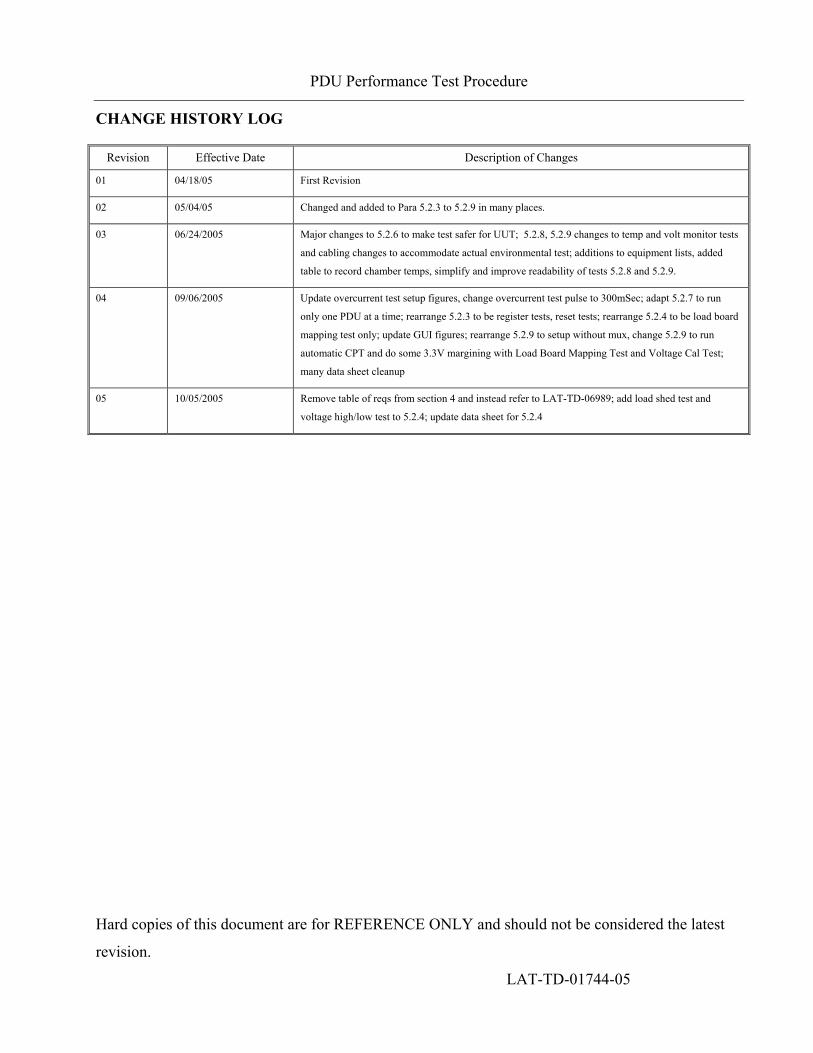
CHANGE HISTORY LOG
Revision Effective Date Description of Changes
01 04/18/05 First Revision
02 05/04/05 Changed and added to Para 5.2.3 to 5.2.9 in many places.
03 06/24/2005 Major changes to 5.2.6 to make test safer for UUT; 5.2.8, 5.2.9 changes to temp and volt monitor tests
and cabling changes to accommodate actual environmental test; additions to equipment lists, added
table to record chamber temps, simplify and improve readability of tests 5.2.8 and 5.2.9.
04 09/06/2005 Update overcurrent test setup figures, change overcurrent test pulse to 300mSec; adapt 5.2.7 to run
only one PDU at a time; rearrange 5.2.3 to be register tests, reset tests; rearrange 5.2.4 to be load board
mapping test only; update GUI figures; rearrange 5.2.9 to setup without mux, change 5.2.9 to run
automatic CPT and do some 3.3V margining with Load Board Mapping Test and Voltage Cal Test;
many data sheet cleanup
05 10/05/2005 Remove table of reqs from section 4 and instead refer to LAT-TD-06989; add load shed test and
voltage high/low test to 5.2.4; update data sheet for 5.2.4

PDU Performance Test Procedure
Hard copies of this document are for REFERENCE ONLY and should not be considered the latest
revision. LAT-TD-01744-05 Page 3
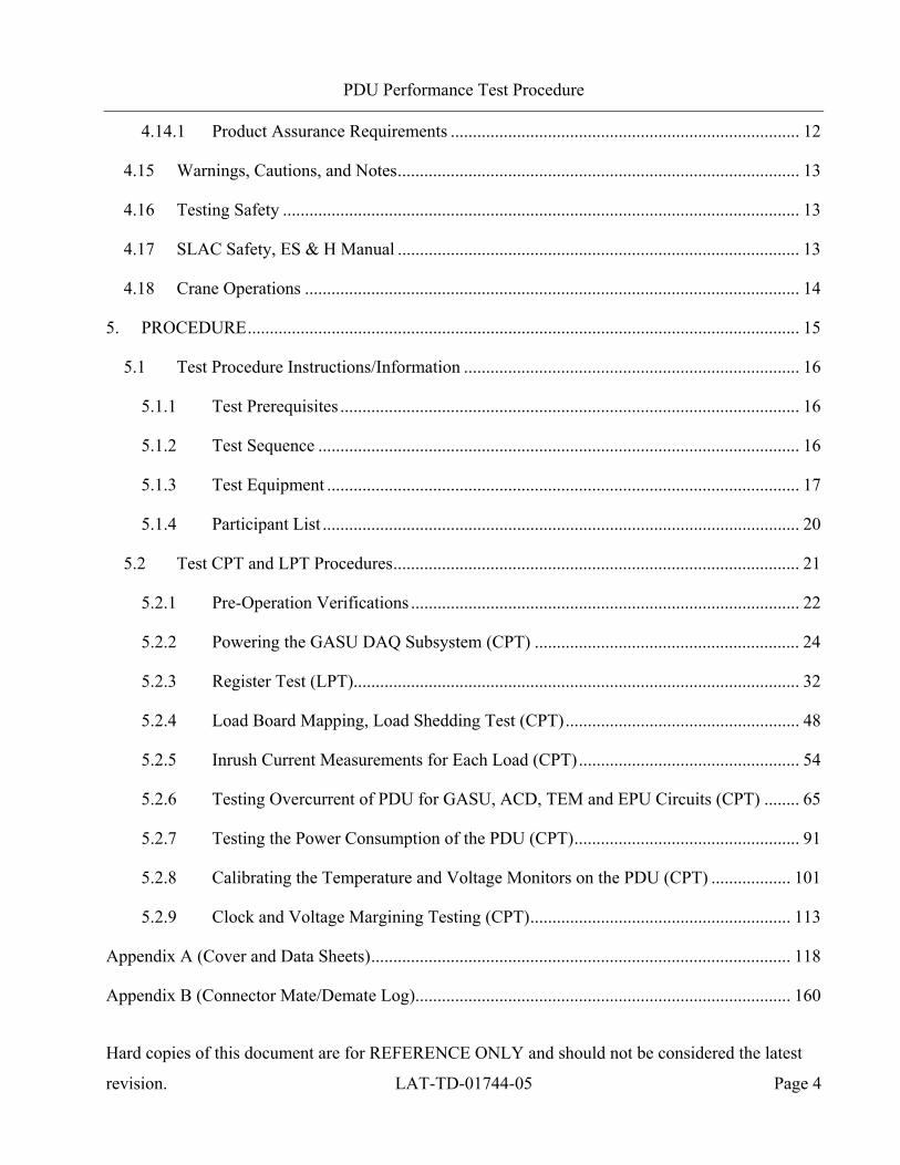
1. SCOPE .......................................................................................................................................... 5
2. DEFINITIONS AND ACRONYMS ............................................................................................ 6
2.1 Definitions............................................................................................................................. 6
2.2 Acronyms.............................................................................................................................. 7
3. REFERENCES ............................................................................................................................. 8
3.1 Applicable Documents.......................................................................................................... 8
4. REQUIREMENTS........................................................................................................................ 9
4.1 General.................................................................................................................................. 9
4.1.1 Specific Test Requirements .......................................................................................... 9
4.2 Test Personnel and Descriptions........................................................................................... 9
4.3 Test Readiness Review (TRR) and Post Test Review (PTR) ............................................... 9
4.4 Environmental Conditions .................................................................................................. 10
4.5 Contamination Control........................................................................................................ 10
4.6 Handling and Transportation .............................................................................................. 10
4.7 ESD..................................................................................................................................... 11
4.8 Mate/Demate Connectors.................................................................................................... 11
4.9 Test Equipment ................................................................................................................... 11
4.10 Test Data and Review ......................................................................................................... 11
4.11 Flight Hardware Log Book ................................................................................................. 11
4.12 Nonconforming Test Data, Equipment and Software......................................................... 12
4.13 Redlining and Blacklining Documents ............................................................................... 12
4.14 Quality Assurance............................................................................................................... 12
PDU Performance Test Procedure
Hard copies of this document are for REFERENCE ONLY and should not be considered the latest
revision. LAT-TD-01744-05 Page 4
4.14.1 Product Assurance Requirements ............................................................................... 12
4.15 Warnings, Cautions, and Notes........................................................................................... 13
4.16 Testing Safety ..................................................................................................................... 13
4.17 SLAC Safety, ES & H Manual ........................................................................................... 13
4.18 Crane Operations ................................................................................................................ 14
5. PROCEDURE............................................................................................................................. 15
5.1 Test Procedure Instructions/Information ............................................................................ 16
5.1.1 Test Prerequisites ........................................................................................................ 16
5.1.2 Test Sequence ............................................................................................................. 16
5.1.3 Test Equipment ........................................................................................................... 17
5.1.4 Participant List ............................................................................................................ 20
5.2 Test CPT and LPT Procedures............................................................................................ 21
5.2.1 Pre-Operation Verifications ........................................................................................ 22
5.2.2 Powering the GASU DAQ Subsystem (CPT) ............................................................ 24
5.2.3 Register Test (LPT)..................................................................................................... 32
5.2.4 Load Board Mapping, Load Shedding Test (CPT)..................................................... 48
5.2.5 Inrush Current Measurements for Each Load (CPT).................................................. 54
5.2.6 Testing Overcurrent of PDU for GASU, ACD, TEM and EPU Circuits (CPT) ........ 65
5.2.7 Testing the Power Consumption of the PDU (CPT)................................................... 91
5.2.8 Calibrating the Temperature and Voltage Monitors on the PDU (CPT) .................. 101
5.2.9 Clock and Voltage Margining Testing (CPT)........................................................... 113
Appendix A (Cover and Data Sheets)............................................................................................... 118
Appendix B (Connector Mate/Demate Log)..................................................................................... 160
PDU Performance Test Procedure
Hard copies of this document are for REFERENCE ONLY and should not be considered the latest
revision. LAT-TD-01744-05 Page 5
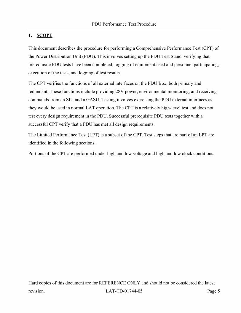
1. SCOPE
This document describes the procedure for performing a Comprehensive Performance Test (CPT) of
the Power Distribution Unit (PDU). This involves setting up the PDU Test Stand, verifying that
prerequisite PDU tests have been completed, logging of equipment used and personnel participating,
execution of the tests, and logging of test results.
The CPT verifies the functions of all external interfaces on the PDU Box, both primary and
redundant. These functions include providing 28V power, environmental monitoring, and receiving
commands from an SIU and a GASU. Testing involves exercising the PDU external interfaces as
they would be used in normal LAT operation. The CPT is a relatively high-level test and does not
test every design requirement in the PDU. Successful prerequisite PDU tests together with a
successful CPT verify that a PDU has met all design requirements.
The Limited Performance Test (LPT) is a subset of the CPT. Test steps that are part of an LPT are
identified in the following sections.
Portions of the CPT are performed under high and low voltage and high and low clock conditions.
PDU Performance Test Procedure
Hard copies of this document are for REFERENCE ONLY and should not be considered the latest
revision. LAT-TD-01744-05 Page 6
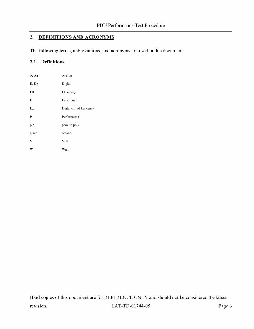
2. DEFINITIONS AND ACRONYMS
The following terms, abbreviations, and acronyms are used in this document:
2.1 Definitions
A, An Analog
D, Dg Digital
Eff Efficiency
F Functional
Hz Hertz, unit of frequency
P Performance
p-p peak-to-peak
s, sec seconds
V Volt
W Watt
PDU Performance Test Procedure
Hard copies of this document are for REFERENCE ONLY and should not be considered the latest
revision. LAT-TD-01744-05 Page 7
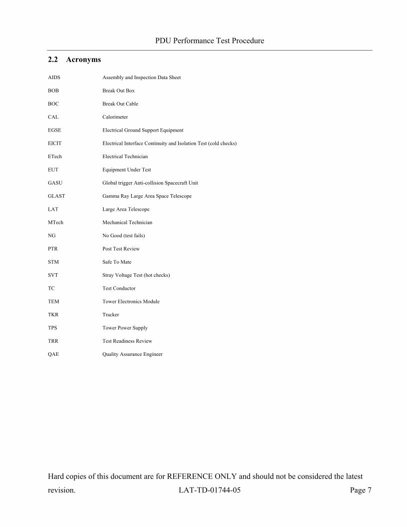
2.2 Acronyms
AIDS Assembly and Inspection Data Sheet
BOB Break Out Box
BOC Break Out Cable
CAL Calorimeter
EGSE Electrical Ground Support Equipment
EICIT Electrical Interface Continuity and Isolation Test (cold checks)
ETech Electrical Technician
EUT Equipment Under Test
GASU Global trigger Anti-collision Spacecraft Unit
GLAST Gamma Ray Large Area Space Telescope
LAT Large Area Telescope
MTech Mechanical Technician
NG No Good (test fails)
PTR Post Test Review
STM Safe To Mate
SVT Stray Voltage Test (hot checks)
TC Test Conductor
TEM Tower Electronics Module
TKR Tracker
TPS Tower Power Supply
TRR Test Readiness Review
QAE Quality Assurance Engineer

PDU Performance Test Procedure
Hard copies of this document are for REFERENCE ONLY and should not be considered the latest
revision. LAT-TD-01744-05 Page 8
3. REFERENCES
The list below provides documents that are to be used as references for this procedure:
3.1 Applicable Documents
Document Number Description
SPECIFICATIONS
LAT-TD-00778 LAT Environmental Specification
LAT-TD-01543 Specification and Programming ICD, PDU
LAT-TD-01743 Specification and Electrical ICD, PDU
LAT-TD-04096 Specification and Electrical ICD, PDU Test Box
LAT-SS-06988 PDU Level V Specification
PROCEDURES
LAT-TD-02544 Test Procedure, PDU CCA
LAT-TD-04332 Test Procedure, PDU EICIT
LAT-TD-04384 Test Procedure, PDU SVT
LAT-TD-04095 Test Procedure, PDU Test Stand Validation
PLANS
LAT-MD-00039 Performance Assurance Implementation Plan
LAT-MD-00078 GLAST LAT System Safety Program Plan
LAT-MD-00228 CAL, TKR, and T& DF Contamination Control Plan
LAT-MD-00404 LAT Contamination Control Plan
LAT-MD-00408 LAT Program Instrument Performance Verification Plan
LAT-MD-01376 GLAST LAT Integration and Test Subsystem Test Plan
LAT-TD-00296 Trigger and Dataflow Test Plan
LAT-MD-02730 LAT Performance and Operations Test Plan
OTHER
LAT-MD-00091 GLAST Quality Manual
LAT-MD-00471 Control of Nonconforming Product
LAT-MD-00472 Corrective and Preventative Action
LAT-MD-00473 Handling, Storage, Packing, Preservation and Delivery
LAT-MD-03474 Redline/Blackline Engineering Documents
LAT-PS-04459 Mate and De-mate Workmanship Standards
PDU Performance Test Procedure
Hard copies of this document are for REFERENCE ONLY and should not be considered the latest
revision. LAT-TD-01744-05 Page 9
4. REQUIREMENTS
This section lists the requirements that shall be utilized during the PDU Qualification and
Acceptance process testing and storage.
4.1 General
The Performance Assurance Implementation Plan, LAT-MD-00039 shall be utilized to verify that
the products produced by the GLAST LAT project intended for design qualification, flight and
critical ground support equipment usage meet the required levels of quality and functionality for
their intended purposes.
This document shall follow the LAT Program Instrument Performance Verification Plan LAT-MD-
00408 which details the LAT and its subsystem verification test flow.
The LAT T & DF Test Plan, LAT-TD-00296 shall be utilized to address the overall requirements at
engineering model, qualification and production level phases. This document defines the time period
from post circuit board fabrication until electronic box delivery to LAT Integration and Test.
Testing within this document shall conform to the requirements stated in LAT Performance and
Operations Test Plan LAT-MD-02730 for all testing that relates to LAT I & T.
4.1.1 Specific Test Requirements
The PDU requirements are listed in LAT-SS-06988, the PDU Level V Source Specification, and
LAT-TD-06989, the PDU Verification Matrix.
4.2 Test Personnel and Descriptions
Test personnel are described in GLAST LAT Integration and Test Subsystem Test Plan, LAT-MD-
01376. The test team members are defined with the following responsibilities:
4.3 Test Readiness Review (TRR) and Post Test Review (PTR)
The TRR and PTR are organizational meetings that shall be held at the appropriate times to inform
all parties about the testing that is to be accomplished and has been completed. The TRR and PTR
PDU Performance Test Procedure
Hard copies of this document are for REFERENCE ONLY and should not be considered the latest
revision. LAT-TD-01744-05 Page 10
meetings are defined in the GLAST LAT Integration and Test Subsystem Test Plan, LAT-MD-
01376.
4.4 Environmental Conditions
Testing performed in accordance with this document shall conform to standard environmental test
conditions unless specific test requirements within this document exist. Standard Environmental test
conditions are as follows:
Dynamic Mechanical Conditions: No load, at rest
Temperature: 18.3 to 25.7°C
Atmospheric Pressure: Uncontrolled local conditions
Humidity: 30% to 50% RH for testing when the Calorimeter or Engineering Model (EM)
Calorimeters are present. For all other testing 30% to 60% RH is required.
This document shall follow the LAT Environmental Specification, LAT-SS-00778 for all testing
where non standard environments are required. The Environmental Specification defines the
thermal, vibration and on-orbit exposure design and test environments for the LAT instrument and
its subsystems.
4.5 Contamination Control
The Contamination Control Plan defines the overall contamination control requirements necessary to
establish hardware cleanliness for the GLAST LAT program. When work is performed at SLAC
follow LAT-MD-01386. When work is performed elsewhere follow LAT-MD-00404.
4.6 Handling and Transportation
This document shall follow the requirements found in the Handling, Storage, Package, Preservation
and Delivery document, LAT-MD-00473. This document establishes handling, storage, packaging
and transportation practices adequate to maintain the safety, reliability and quality of SLAC LAT
flight hardware items and achieve their damage free delivery to the place and time of ultimate use.
PDU Performance Test Procedure
Hard copies of this document are for REFERENCE ONLY and should not be considered the latest
revision. LAT-TD-01744-05 Page 11
4.7 ESD
The CAL, TKR, T & DF Contamination Control Plan and the LAT Contamination Control Plan
define the ESD requirements for the GLAST LAT program. When work is performed at SLAC
follow LAT-MD-01386. When work is performed elsewhere follow LAT-MD-00404.
4.8 Mate/Demate Connectors
This document shall follow the requirements found in the Mate and Demate Workmanship Standard
LAT-PS-04459. The mate/demate process shall be followed for each and every connector mate. This
consists of a visual inspection of the interface, cleaning if required, and proper mating techniques.
4.9 Test Equipment
This document shall follow the requirements found in the LAT Program Instrument Performance
Verification Plan, LAT-MD-00408, which defines calibration, accuracy, substitutions, etc. for the
test equipment.
4.10 Test Data and Review
This document shall follow the requirements found in the LAT Program Instrument Performance
Verification Plan, LAT-MD-00408, which defines the test data sheets and details the personnel that
reviews test data. Test data shall be recorded on the data sheets that are found in Appendix A of this
document. The data sheets and any supporting data shall use a cover sheet that is found in Appendix
A of this document.
4.11 Flight Hardware Log Book
The LAT Program Instrument Performance Verification Plan, LAT-MD-00408 requires that a log of
hardware installation, software installation, power ON and mates/demates to flight connectors shall
be kept for each flight unit. The log book is part of the package that is deliverable to the customer.
PDU Performance Test Procedure
Hard copies of this document are for REFERENCE ONLY and should not be considered the latest
revision. LAT-TD-01744-05 Page 12
4.12 Nonconforming Test Data, Equipment and Software
This document shall follow the requirements found in the Control of Nonconforming Product, LAT-
MD-00471. This document establishes methods to identify and control nonconforming product
developed by the LAT project team.
4.13 Redlining and Blacklining Documents
The users of this document shall follow the requirements found in the Redline/Blackline Engineering
Documents, LAT-MD-03474.
4.14 Quality Assurance
This document shall follow the requirements found in the Corrective and Preventative Action
document, LAT-MD-00472 and the GLAST Quality Manual, LAT-MD-00091 and LAT Program
Instrument Performance Verification Plan, LAT-MD-00408.
The Corrective and Preventative Action document establishes the method to be used to initiate,
implement, evaluate and record corrective and preventive actions. The GLAST Quality Manual
defines the methods implemented by the GLAST LAT project to verify consistent quality of all
processes for procurement, design, development and production of flight hardware, flight software,
calibration and all associated ground support equipment interfacing with flight hardware and
software. The LAT Program Instrument Performance Verification Plan defines test configuration,
data sheets and review of test results.
4.14.1 Product Assurance Requirements
The QAE shall witness the initial test setup and validation operations. In the event of a failure a Non
Conformance Report (NCR) shall be written. The root cause and corrective action shall be identified
and there shall be QAE approval before the operation is continued. Any deviation from this
document requires approval from the QAE as well as the TC.

PDU Performance Test Procedure
Hard copies of this document are for REFERENCE ONLY and should not be considered the latest
revision. LAT-TD-01744-05 Page 13
4.15 Warnings, Cautions, and Notes
The following SAFETY ALERTS are intended to create awareness of the potential safety hazards
and the steps that must be taken to avoid accidents. These same alerts are used throughout this
document to identify specific hazards that may endanger personnel and/or equipment.
Identification of every conceivable hazardous situation is impossible. Therefore, all personnel have
the responsibility to diligently exercise safe practices whenever exposed to this equipment.
Indicates a potential hazardous situation which, if not avoided, could result in death or injury.
Indicates a potential hazardous situation which, if not avoided, could result in damage to equipment.
Indicates a notification of information that is important, but not hazard related.
4.16 Testing Safety
This document shall follow the requirements found in the GLAST LAT System Safety Program
Plan, LAT-MD-00078. This document defines all phases of the LAT program including: design,
development, fabrication, handling, transportation, storage, test, assembly and operation.
4.17 SLAC Safety, ES & H Manual
This document shall follow the requirements found in the SLAC Environment, Safety, and Health
Manual, SLAC-I-720-0A29Z-001. This document defines the SLAC policy to support
environmental protection, health, and safety in the workplace.
A hot work permit is required for work on or around open connectors/circuits having:
Voltage greater than 50V (AC or DC)
AND
Current supply capability greater than 5mA
OR any circuit having
Energy storage greater than 10 Joules (E=1/2CV²)

PDU Performance Test Procedure
Hard copies of this document are for REFERENCE ONLY and should not be considered the latest
revision. LAT-TD-01744-05 Page 14
4.18 Crane Operations
Before a crane (or any lifting device) is used it should be verified that the proof loading is current
and the expected load to be lifted does not exceed the load capacity of the device. The operator shall
have a current certification for the operation.
There shall be three people present before, during and at the completion of all lifting operations.
Each one of these people shall perform only one of the following three duties:
Crane Operator – When the crane operator controls the crane no other duties shall be performed.
At other times this person may help with the mechanical or electrical duties.
Spotter – During the lifting operation this person guides the item that is to be moved up or down,
checks clearances and the overall movement of all items. At other times this person may help
with the mechanical or electrical duties.
Safety Person (for crane operations only) – Before lifting the item, this person double checks all
operations and the removal of bolts/hardware from the item to be moved. During crane
operations this person is an observer of the operation and directs the overall lifting operation.

PDU Performance Test Procedure
Hard copies of this document are for REFERENCE ONLY and should not be considered the latest
revision. LAT-TD-01744-05 Page 15
5. PROCEDURE
The following statement is used for powered tests. If the power levels are above the safe working
limits the proper WARNINGS and instructions must be written into the procedure.
This procedure is used for the Comprehensive Performance Test (CPT) of the PDU. Portions of this
procedure also verify PDU requirements. A subset of the CPT is used as a Limited Performance Test
(LPT). Test steps that are part of the LPT are identified as such in the procedures below.
This document is written so that there is no exposed connectors/circuitry of more than the safe
working limits as stated in the SLAC Environment, Safety, and Health Manual,
SLAC-I-720-0A29Z-001.
This document shall be considered subordinate to any Assembly and Inspection Data Sheet (AIDS)
that is used in conjunction with this testing process.
Unless otherwise noted use a DMM for all measurements.
When performing measurements with a DMM connect the negative lead first.
PDU Performance Test Procedure
Hard copies of this document are for REFERENCE ONLY and should not be considered the latest
revision. LAT-TD-01744-05 Page 16
5.1 Test Procedure Instructions/Information
This section provides the general instructions and information that is used and required to perform
this procedure, including: test parameters, sequence, equipment and Test Participants.
5.1.1 Test Prerequisites
This section describes processes and procedures that must be completed prior to performing the tests
in this document.
Before the CPT or the LPT, the following tests must be completed:
LAT-TD-04332: PDU EICIT Procedure
LAT-TD-02544: PDU CCA Test Procedure
LAT-TD-04384: PDU SVT Procedure
An EICIT and SVT must be performed before this test is to be accomplished.
This test procedure is executed as part of the LAT-TD-02544 procedure so in that context, this
procedure is performed as part of LAT-TD-02544 completion.
5.1.2 Test Sequence
This section describes the requirements of the event sequence for performing this procedure. Tests
are to be performed in the order listed in this document unless otherwise specified. It is permissible
for AIDS to be used to change the order of tests or select a single test paragraph to be performed. In
that case, the data sheet for the test performed will be included in the end item data package linked to
the AIDS step that required it. Test sequencing can also be changed in a TRR and black lined into
the test procedure.

PDU Performance Test Procedure
Hard copies of this document are for REFERENCE ONLY and should not be considered the latest
revision. LAT-TD-01744-05 Page 17
5.1.3 Test Equipment
The test equipment listed below is necessary for the tests described in this procedure. If additional
equipment is used, please add it to the data sheet with the signature of the TC and QAE.
5.1.3.1 EGSE
The figure below illustrates the complete PDU Test Stand for executing most tests. Some tests
require the insertion of BOBs and BOCs between connectors or the use of alternate cables to connect
two points. These exceptions to the illustrated test setup are noted in the procedure where needed.
Completed PDU Test Stand Block Diagram
PDU Performance Test Procedure
Hard copies of this document are for REFERENCE ONLY and should not be considered the latest
revision. LAT-TD-01744-05 Page 18
To record the test equipment, cables, connector savers and software:
1) Record the information for all equipment on the data sheet. See the list below for descriptions
of the information to be recorded.
Description and Manufacturer
Model/LAT number (Data Logger and cards, etc)
Serial/Revision number (for equipment, files and software)
Calibration due date (enter NA for non calibrated equipment)
Validation completion date for all EGSE

PDU Performance Test Procedure
Hard copies of this document are for REFERENCE ONLY and should not be considered the latest
revision. LAT-TD-01744-05 Page 19
The list below indicates the equipment that is known to be used to perform this procedure:
Test Equipment Description, Manufacturer Model/LAT Number
Digital Multimeter, Fluke/Meterman * 87-III/38XR
Digital Multimeter, Precision, Agilent 34401A
Digital Oscilloscope, Tektronix TDS 2024
80 MHz Function Generator, Agilent 33250A
Switch Unit, Agilent 34970A
DAQ Cable Assy, Datalog Interface EGSE, SLAC (two needed) LAT-DS-04612
JL5 to Switch Unit Relays adapter cable, SLAC LAT-DS-06868
Local PC
1200W Variable DC Power Supply, Xantrex Technology XFR35-35
DC Power Supply, BK Precision (one needed) 1697
DC Power Supply, BK Precision (two needed) 1786A
VME Crate, DawnVME 11-1011777-2119
VME Single Board Computer, Motorola MVME2304-0123 SBC v 0143 r VXWORKS 5.5
VME LAT Comm Board (mezzanine version), SLAC LAT-DS-03253
VME6U Slave 5slot IP Module Carrier, Systran VMESC5
8 channel 12bit DAC board, IP Module, Systran (five needed) DAC128V
DAC Board to PDU Vmon Cable, SLAC (five needed) LAT-DS-05940
CAT5 Ethernet Cable, standard TRD855PL-50
CAT5 Ethernet Cable, crossover
RS-232 Cable TDC003-7 (RECO98M connectors)
RS-232 Cable, DB9MF, straight-thru (three needed)
RS-232 Cable, DB9FF, crossover (two needed)
Ultra Port USB8, USB to 8 serial port hub, Perle Systems 04025084
Software, LATTE, SLAC Current version
Software, PDU Test Scripts, SLAC Current version
BNC to Banana plug pair, SLAC (two needed) LAT-DS-05964
Overcurrent Test Box, SLAC LAT-DS-06711
Banana plug to Pin plug, SLAC (four needed) LAT-DS-05966
GASU Box Assy, SLAC LAT-DS-01611
GASU Crate Cable, SLAC LAT-DS-02104
GASU Test Box, SLAC LAT-DS-04969
GASU to Test Box Cable, SLAC LAT-DS-05218
GASU Test Box Power Cable, SLAC LAT-DS-03246
PDU Test Box Assy, SLAC LAT-DS-03400
PDU Test Cable – No GASU, SLAC (two needed) LAT-DS-04304
PDU Test Cable – GASU, SLAC (two needed) LAT-DS-05550
PDU Test Cable – Power, SLAC LAT-DS-04309
PDU Test Cable – 16 Temp Sensors, SLAC (three needed) LAT-DS-04305
PDU Test Cable – 38 Temp Sensors, SLAC (four needed) LAT-DS-04306
PDU Test Cable – EPU/TEM, SLAC (19 needed) LAT-DS-04308
PDU Test Cable – Inrush Current Test, SLAC LAT-DS-05930

PDU Performance Test Procedure
Hard copies of this document are for REFERENCE ONLY and should not be considered the latest
revision. LAT-TD-01744-05 Page 20
Test Equipment Description, Manufacturer Model/LAT Number
GASU to PDU Cable, SLAC LAT-DS-02103
PDU Test 264 Temp Sensors Board, SLAC LAT-DS-03409-02 VERSION 7590
PDU Test 264 Temp Sensors Board, SLAC LAT-DS-03409-02 VERSION 19800
PDU Test 264 Temp Sensors Board, SLAC LAT-DS-03409-02 VERSION 30100
PDU Test 264 Temp Sensors Board, SLAC LAT-DS-03409-02 VERSION 60400
PDU Test 264 Temp Sensors Board, SLAC LAT-DS-03409-02 VERSION 205000
PDU Test 264 Temp Sensors Board, SLAC LAT-DS-03409-02 VERSION 361000
PDU Test 264 Temp Sensors Board, SLAC LAT-DS-03409-02 VERSION 806000
BOB 26 pin, SLAC (two needed) LAT-DS-03578
BOB 78 pin, SLAC LAT-DS-03580
BOC connects 26M to BOB 26F, SLAC (two needed) LAT-DS-04298
BOC connects 26F to BOB 26M, SLAC (two needed) LAT-DS-04299
BOC connects 78M to BOB 78F, SLAC LAT-DS-04302
BOC connects 78F to BOB 78M, SLAC LAT-DS-04303
∗ Do not substitute other DMM's
CAUTION: Fluke 87-III and Fluke 87-V are not the same, Fluke 87-V is not allowed.
5.1.4 Participant List
This section provides a data sheet to record test participants.
Record all test participants in the data sheet.

PDU Performance Test Procedure
Hard copies of this document are for REFERENCE ONLY and should not be considered the latest
revision. LAT-TD-01744-05 Page 21
5.2 Test CPT and LPT Procedures
The EUT is the assembled PDU Box (LAT-DS-01696). The EUT serial number is the 4-digit part of
the GLATxxxx barcode number affixed to the PDU chassis. Record this number on the test data
sheets as required and enter them in the Run Control Main application window when asked.
The tests in this document require the user do the following things:
Mate and demate cables and BOBs in the EGSE setup
Use an oscilloscope and multi-meter
Read the current display on the power supply
Visually verify that LEDs on the PDU Test Box illuminate
Set DIP switches on the PDU Test Box
Configure the GASU to run from an external clock source
Open the Run Control Main application of LATTE and run Python scripts

PDU Performance Test Procedure
Hard copies of this document are for REFERENCE ONLY and should not be considered the latest
revision. LAT-TD-01744-05 Page 22
5.2.1 Pre-Operation Verifications
This section details the pre-operation verification checks before testing the EUT.
To perform the pre-operation verification checks:
Follow ESD processes during this checkout.
Prior to the connection of any hardware to other electronics, it shall be verified that all power
supplies, signal generators, VME racks, and any other test and measurement
equipment shall be connected to the same AC ground. The simplest way to do this is
to connect all AC-powered equipment to the same power strip. In cases where this is
not practical (e.g. possibly a thermal-vacuum test), greater care must be taken to
verify there are no floating grounds since this would represent a hazard to the
electronics.
Leave all connector savers in place until the actual flight mate is to be made. The AIDS provides
authorization to install and remove connector savers.
All flight mates and demates must be completed and entered into the mate demate log before
measurements are made or testing can start.
1) Notify QAE that testing is expected to start, so the QAE can arrange to be present for the
setup and start of testing. Record in the data sheet.
2) Verify that the Test Readiness Review has concluded and all parties have signed the cover
sheet. Record in the data sheet.
3) Record the serial numbers and locations per the data sheet.
4) Turn OFF the power on the LAT, or the EGSE. Record in the data sheet.

PDU Performance Test Procedure
Hard copies of this document are for REFERENCE ONLY and should not be considered the latest
revision. LAT-TD-01744-05 Page 23
5) Set the DMM to the auto-ranging setting. Record in the data sheet.
6) Measure DMM lead resistance by connecting the two leads together. Record in the data sheet.
7) Tie the BOB chassis to technical ground. Measure the resistance between the BOB chassis and
technical ground. Record in the data sheet.
8) Remove all shorting plugs from the BOB. Record in the data sheet.
9) Measure the resistance between the EUT chassis and technical ground. Record in the data
sheet.
10) Measure the resistance between the test equipment chassis and technical ground. Record in the
data sheet.
11) Verify connector savers are on all flight hardware (install the connector savers per
authorization from an AIDS if necessary). Record in the data sheet.
12) Verify that the test equipment and participant lists have been completed.
PDU Performance Test Procedure
Hard copies of this document are for REFERENCE ONLY and should not be considered the latest
revision. LAT-TD-01744-05 Page 24
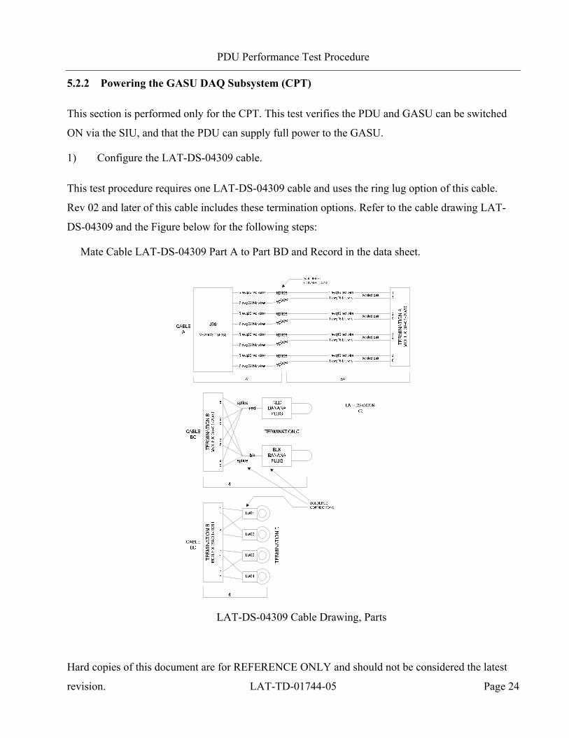
5.2.2 Powering the GASU DAQ Subsystem (CPT)
This section is performed only for the CPT. This test verifies the PDU and GASU can be switched
ON via the SIU, and that the PDU can supply full power to the GASU.
1) Configure the LAT-DS-04309 cable.
This test procedure requires one LAT-DS-04309 cable and uses the ring lug option of this cable.
Rev 02 and later of this cable includes these termination options. Refer to the cable drawing LAT-
DS-04309 and the Figure below for the following steps:
Mate Cable LAT-DS-04309 Part A to Part BD and Record in the data sheet.
LAT-DS-04309 Cable Drawing, Parts
PDU Performance Test Procedure
Hard copies of this document are for REFERENCE ONLY and should not be considered the latest
revision. LAT-TD-01744-05 Page 25
2) Turn ON the 28VDC Xantrex power supply.
3) Set the power supply output at 28.4V and set the current limit to 30A.
4) Record the voltage output and record the current limit setting of the power supply per the data
sheet.
5) Turn OFF the power supply.
6) Configure the PDU Test setup per the steps below and referenced in the following Figure.
a) Mate LAT-DS-04309 by connecting the red wired lugs to the positive terminal of the
power supply and the black wired lugs to the negative terminal of the power supply.
Record in the data sheet.
b) Mate LAT-DS-04307 JL5 flying cable from Test Box to PDU JL5. Record in the data
sheet.
c) Mate LAT-DS-04307 JL6 flying cable from Test Box to PDU JL6. Record in the data
sheet.
d) Mate LAT-DS-03400 JL7 pigtail from Test Box to LAT-DS-04304 J20. Record in the
data sheet.
e) Mate LAT-DS-04304 J78 to PDU JL7. Record in the data sheet.
Note: All mates and demates to the PDU under test are made at the connector saver only.
Only an AIDS provides the authorization to mate and demate flight connectors.
f) Mate LAT-DS-03400 JL8 pigtail from Test box to LAT-DS-04304 J20. Record in the
data sheet.
g) Mate LAT-DS-04304 J78 to PDU JL8. Record in the data sheet.
h) Hard ground the return bar of the Xantrex power supply. The PDU case and the return
bar must be connected to the same ground.
PDU Performance Test Procedure
Hard copies of this document are for REFERENCE ONLY and should not be considered the latest
revision. LAT-TD-01744-05 Page 26
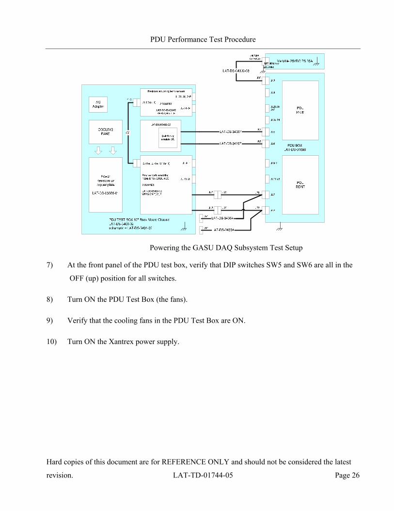
Powering the GASU DAQ Subsystem Test Setup
7) At the front panel of the PDU test box, verify that DIP switches SW5 and SW6 are all in the
OFF (up) position for all switches.
8) Turn ON the PDU Test Box (the fans).
9) Verify that the cooling fans in the PDU Test Box are ON.
10) Turn ON the Xantrex power supply.
PDU Performance Test Procedure
Hard copies of this document are for REFERENCE ONLY and should not be considered the latest
revision. LAT-TD-01744-05 Page 27
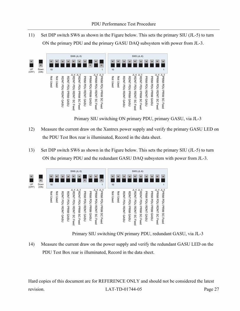
11) Set DIP switch SW6 as shown in the Figure below. This sets the primary SIU (JL-5) to turn
ON the primary PDU and the primary GASU DAQ subsystem with power from JL-3.
UP(OFF)
Down(ON)
X
X
X
X
X XX XX X X
X
PR
IM P
DU
PR
IM S
C Feed
PR
IM P
DU
RD
NT S
C Feed
PR
IM P
DU
PR
IM G
AS
U
PR
IM P
DU
RD
NT G
AS
U
RD
NT P
DU
PR
IM S
C Feed
RD
NT P
DU
RD
NT S
C Feed
RD
NT P
DU
PR
IM G
AS
U
RD
NT P
DU
RD
NT G
AS
U
Not U
sed
Not U
sed
10 1
JL-3JL-4JL-3JL-4
X XX XX XX X X X
PR
IM P
DU
PR
IM S
C Feed
PR
IM P
DU
RD
NT S
C Feed
PR
IM P
DU
PR
IM G
AS
U
PR
IM P
DU
RD
NT G
AS
U
RD
NT P
DU
PR
IM S
C Feed
RD
NT P
DU
RD
NT S
C Feed
RD
NT P
DU
PR
IM G
AS
U
RD
NT P
DU
RD
NT G
AS
U
Not U
sed
Not U
sed
10 1
JL-3JL-4JL-3JL-4
SW6 (JL-5) SW5 (JL-6)
Primary SIU switching ON primary PDU, primary GASU, via JL-3
12) Measure the current draw on the Xantrex power supply and verify the primary GASU LED on
the PDU Test Box rear is illuminated, Record in the data sheet.
13) Set DIP switch SW6 as shown in the Figure below. This sets the primary SIU (JL-5) to turn
ON the primary PDU and the redundant GASU DAQ subsystem with power from JL-3.
UP(OFF)
Down(ON)
X
X
X
X
X XX XX X
X
X
PR
IM P
DU
PR
IM S
C Feed
PR
IM P
DU
RD
NT S
C Feed
PR
IM P
DU
PR
IM G
AS
U
PR
IM P
DU
RD
NT G
AS
U
RD
NT P
DU
PR
IM S
C Feed
RD
NT P
DU
RD
NT S
C Feed
RD
NT P
DU
PR
IM G
AS
U
RD
NT P
DU
RD
NT G
AS
U
Not U
sed
Not U
sed10 1
JL-3JL-4JL-3JL-4
X XX XX XX X X X
PR
IM P
DU
PR
IM S
C Feed
PR
IM P
DU
RD
NT S
C Feed
PR
IM P
DU
PR
IM G
AS
U
PR
IM P
DU
RD
NT G
AS
U
RD
NT P
DU
PR
IM S
C Feed
RD
NT P
DU
RD
NT S
C Feed
RD
NT P
DU
PR
IM G
AS
U
RD
NT P
DU
RD
NT G
AS
U
Not U
sed
Not U
sed
10 1
JL-3JL-4JL-3JL-4
SW6 (JL-5) SW5 (JL-6)
Primary SIU switching ON primary PDU, redundant GASU, via JL-3
14) Measure the current draw on the power supply and verify the redundant GASU LED on the
PDU Test Box rear is illuminated, Record in the data sheet.
PDU Performance Test Procedure
Hard copies of this document are for REFERENCE ONLY and should not be considered the latest
revision. LAT-TD-01744-05 Page 28
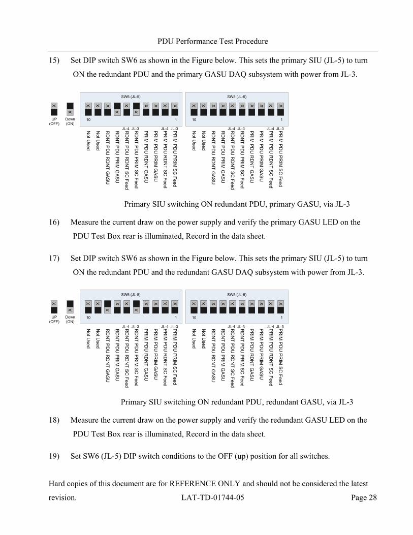
15) Set DIP switch SW6 as shown in the Figure below. This sets the primary SIU (JL-5) to turn
ON the redundant PDU and the primary GASU DAQ subsystem with power from JL-3.
UP(OFF)
Down(ON)
X
X
X XX X X
X
X
X
X X
PR
IM P
DU
PR
IM S
C Feed
PR
IM P
DU
RD
NT S
C Feed
PR
IM P
DU
PR
IM G
AS
U
PR
IM P
DU
RD
NT G
AS
U
RD
NT P
DU
PR
IM S
C Feed
RD
NT P
DU
RD
NT S
C Feed
RD
NT P
DU
PR
IM G
AS
U
RD
NT P
DU
RD
NT G
AS
U
Not U
sed
Not U
sed
10 1
JL-3JL-4JL-3JL-4
X XX XX XX X X X
PR
IM P
DU
PR
IM S
C Feed
PR
IM P
DU
RD
NT S
C Feed
PR
IM P
DU
PR
IM G
AS
U
PR
IM P
DU
RD
NT G
AS
U
RD
NT P
DU
PR
IM S
C Feed
RD
NT P
DU
RD
NT S
C Feed
RD
NT P
DU
PR
IM G
AS
U
RD
NT P
DU
RD
NT G
AS
U
Not U
sed
Not U
sed
10 1
JL-3JL-4JL-3JL-4
SW6 (JL-5) SW5 (JL-6)
Primary SIU switching ON redundant PDU, primary GASU, via JL-3
16) Measure the current draw on the power supply and verify the primary GASU LED on the
PDU Test Box rear is illuminated, Record in the data sheet.
17) Set DIP switch SW6 as shown in the Figure below. This sets the primary SIU (JL-5) to turn
ON the redundant PDU and the redundant GASU DAQ subsystem with power from JL-3.
UP(OFF)
Down(ON)
X
X
X XX X X
XX
X X X
PR
IM P
DU
PR
IM S
C Feed
PR
IM P
DU
RD
NT S
C Feed
PR
IM P
DU
PR
IM G
AS
U
PR
IM P
DU
RD
NT G
AS
U
RD
NT P
DU
PR
IM S
C Feed
RD
NT P
DU
RD
NT S
C Feed
RD
NT P
DU
PR
IM G
AS
U
RD
NT P
DU
RD
NT G
AS
U
Not U
sed
Not U
sed10 1
JL-3JL-4JL-3JL-4
X XX XX XX X X X
PR
IM P
DU
PR
IM S
C Feed
PR
IM P
DU
RD
NT S
C Feed
PR
IM P
DU
PR
IM G
AS
U
PR
IM P
DU
RD
NT G
AS
U
RD
NT P
DU
PR
IM S
C Feed
RD
NT P
DU
RD
NT S
C Feed
RD
NT P
DU
PR
IM G
AS
U
RD
NT P
DU
RD
NT G
AS
U
Not U
sed
Not U
sed
10 1
JL-3JL-4JL-3JL-4
SW6 (JL-5) SW5 (JL-6)
Primary SIU switching ON redundant PDU, redundant GASU, via JL-3
18) Measure the current draw on the power supply and verify the redundant GASU LED on the
PDU Test Box rear is illuminated, Record in the data sheet.
19) Set SW6 (JL-5) DIP switch conditions to the OFF (up) position for all switches.

PDU Performance Test Procedure
Hard copies of this document are for REFERENCE ONLY and should not be considered the latest
revision. LAT-TD-01744-05 Page 29
20) Set DIP switch SW5 as shown in the Figure below. This sets the redundant SIU (JL-6) to turn
ON the primary PDU and the primary GASU DAQ subsystem with power from JL-3.
UP(OFF)
Down(ON)
X
X
X XX X XXX X X X
PR
IM P
DU
PR
IM S
C Feed
PR
IM P
DU
RD
NT S
C Feed
PR
IM P
DU
PR
IM G
AS
U
PR
IM P
DU
RD
NT G
AS
U
RD
NT P
DU
PR
IM S
C Feed
RD
NT P
DU
RD
NT S
C Feed
RD
NT P
DU
PR
IM G
AS
U
RD
NT P
DU
RD
NT G
AS
U
Not U
sed
Not U
sed
10 1
JL-3JL-4JL-3JL-4
X
X
X XX XX X X
X
PR
IM P
DU
PR
IM S
C Feed
PR
IM P
DU
RD
NT S
C Feed
PR
IM P
DU
PR
IM G
AS
U
PR
IM P
DU
RD
NT G
AS
U
RD
NT P
DU
PR
IM S
C Feed
RD
NT P
DU
RD
NT S
C Feed
RD
NT P
DU
PR
IM G
AS
U
RD
NT P
DU
RD
NT G
AS
U
Not U
sed
Not U
sed
10 1
JL-3JL-4JL-3JL-4
SW6 (JL-5) SW5 (JL-6)
Redundant SIU switching ON primary PDU, primary GASU, via JL-3
21) Measure the current draw on the power supply and verify the primary GASU LED on the
PDU Test Box rear is illuminated, Record in the data sheet.
22) Set DIP switch SW5 as shown in the Figure below. This sets the redundant SIU (JL-6) to turn
ON the primary PDU and the redundant GASU DAQ subsystem with power from JL-3.
UP(OFF)
Down(ON)
X
X
X XX X XXX X X X
PR
IM P
DU
PR
IM S
C Feed
PR
IM P
DU
RD
NT S
C Feed
PR
IM P
DU
PR
IM G
AS
U
PR
IM P
DU
RD
NT G
AS
U
RD
NT P
DU
PR
IM S
C Feed
RD
NT P
DU
RD
NT S
C Feed
RD
NT P
DU
PR
IM G
AS
U
RD
NT P
DU
RD
NT G
AS
U
Not U
sed
Not U
sed10 1
JL-3JL-4JL-3JL-4
X
X
X XX XX X
X
X
PR
IM P
DU
PR
IM S
C Feed
PR
IM P
DU
RD
NT S
C Feed
PR
IM P
DU
PR
IM G
AS
U
PR
IM P
DU
RD
NT G
AS
U
RD
NT P
DU
PR
IM S
C Feed
RD
NT P
DU
RD
NT S
C Feed
RD
NT P
DU
PR
IM G
AS
U
RD
NT P
DU
RD
NT G
AS
U
Not U
sed
Not U
sed
10 1
JL-3JL-4JL-3JL-4
SW6 (JL-5) SW5 (JL-6)
Redundant SIU switching ON primary PDU, redundant GASU, via JL3
23) Measure the current draw on the power supply and verify the redundant GASU LED on the
PDU Test Box rear is illuminated, Record in the data sheet.
PDU Performance Test Procedure
Hard copies of this document are for REFERENCE ONLY and should not be considered the latest
revision. LAT-TD-01744-05 Page 30
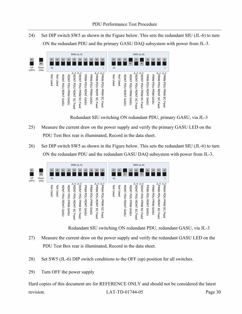
24) Set DIP switch SW5 as shown in the Figure below. This sets the redundant SIU (JL-6) to turn
ON the redundant PDU and the primary GASU DAQ subsystem with power from JL-3.
UP(OFF)
Down(ON)
X
X
X XX X XXX X X X
PR
IM P
DU
PR
IM S
C Feed
PR
IM P
DU
RD
NT S
C Feed
PR
IM P
DU
PR
IM G
AS
U
PR
IM P
DU
RD
NT G
AS
U
RD
NT P
DU
PR
IM S
C Feed
RD
NT P
DU
RD
NT S
C Feed
RD
NT P
DU
PR
IM G
AS
U
RD
NT P
DU
RD
NT G
AS
U
Not U
sed
Not U
sed
10 1
JL-3JL-4JL-3JL-4
X XX XX
X
X
X
X X
PR
IM P
DU
PR
IM S
C Feed
PR
IM P
DU
RD
NT S
C Feed
PR
IM P
DU
PR
IM G
AS
U
PR
IM P
DU
RD
NT G
AS
U
RD
NT P
DU
PR
IM S
C Feed
RD
NT P
DU
RD
NT S
C Feed
RD
NT P
DU
PR
IM G
AS
U
RD
NT P
DU
RD
NT G
AS
U
Not U
sed
Not U
sed
10 1
JL-3JL-4JL-3JL-4
SW6 (JL-5) SW5 (JL-6)
Redundant SIU switching ON redundant PDU, primary GASU, via JL-3
25) Measure the current draw on the power supply and verify the primary GASU LED on the
PDU Test Box rear is illuminated, Record in the data sheet.
26) Set DIP switch SW5 as shown in the Figure below. This sets the redundant SIU (JL-6) to turn
ON the redundant PDU and the redundant GASU DAQ subsystem with power from JL-3.
UP(OFF)
Down(ON)
X
X
X XX X XXX X X X
PR
IM P
DU
PR
IM S
C Feed
PR
IM P
DU
RD
NT S
C Feed
PR
IM P
DU
PR
IM G
AS
U
PR
IM P
DU
RD
NT G
AS
U
RD
NT P
DU
PR
IM S
C Feed
RD
NT P
DU
RD
NT S
C Feed
RD
NT P
DU
PR
IM G
AS
U
RD
NT P
DU
RD
NT G
AS
U
Not U
sed
Not U
sed
10 1
JL-3JL-4JL-3JL-4
X XX XX
XX
X X X
PR
IM P
DU
PR
IM S
C Feed
PR
IM P
DU
RD
NT S
C Feed
PR
IM P
DU
PR
IM G
AS
U
PR
IM P
DU
RD
NT G
AS
U
RD
NT P
DU
PR
IM S
C Feed
RD
NT P
DU
RD
NT S
C Feed
RD
NT P
DU
PR
IM G
AS
U
RD
NT P
DU
RD
NT G
AS
U
Not U
sed
Not U
sed
10 1
JL-3JL-4JL-3JL-4
SW6 (JL-5) SW5 (JL-6)
Redundant SIU switching ON redundant PDU, redundant GASU, via JL-3
27) Measure the current draw on the power supply and verify the redundant GASU LED on the
PDU Test Box rear is illuminated, Record in the data sheet.
28) Set SW5 (JL-6) DIP switch conditions to the OFF (up) position for all switches.
29) Turn OFF the power supply
PDU Performance Test Procedure
Hard copies of this document are for REFERENCE ONLY and should not be considered the latest
revision. LAT-TD-01744-05 Page 31
30) Perform the following demates.
a) Demate LAT-DS-03400 JL7 pigtail from LAT-DS-04304 J20. Record in the data sheet.
b) Demate LAT-DS-04304 J78 from PDU JL7. Record in the data sheet.
c) Demate LAT-DS-03400 JL8 pigtail from LAT-DS-04304 J20. Record in the data sheet.
d) Demate LAT-DS-04304 J78 from PDU JL8. Record in the data sheet.
e) Remove the hard ground from the Xantrex return bar. The PDU case ground should
still be hard grounded. The Xantrex should be soft grounded via 75 ohms to PDU case
ground (which should be the same as earth ground).
PDU Performance Test Procedure
Hard copies of this document are for REFERENCE ONLY and should not be considered the latest
revision. LAT-TD-01744-05 Page 32
5.2.3 Register Test (LPT)
This section is performed during LPT and CPT. During CPT, this test is also executed under voltage
margining, clock margining, and temperature extreme conditions. This test verifies register accesses
of the PDU, including resets and TEM and CRATE power registers.
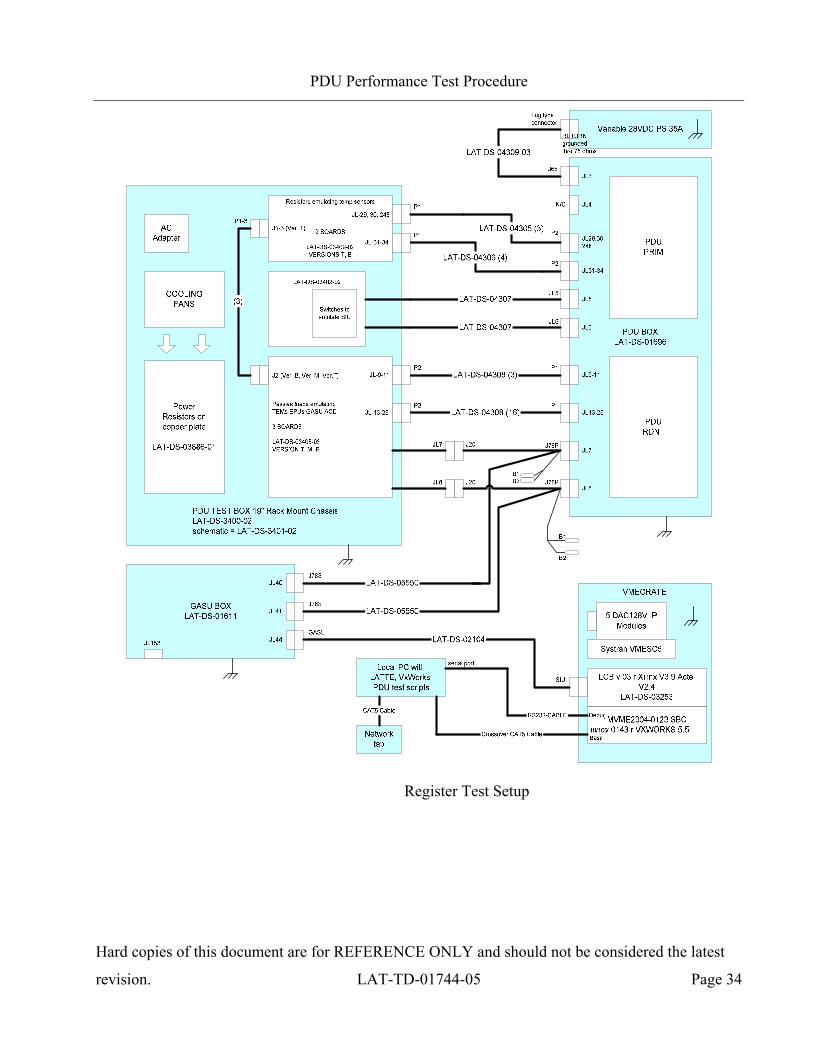
1) Configure the PDU Test setup per the steps below and referenced in the following Figure.
a) Mate LAT-DS-03400 JL7 pigtail to LAT-DS-05550 J20. Record in the data sheet.
b) Mate LAT-DS-05550 J78P to PDU JL7. Record in the data sheet.
c) Mate LAT-DS-03400 JL8 pigtail to LAT-DS-05550 J20. Record in the data sheet.
d) Mate LAT-DS-05550 J78P to PDU JL8. Record in the data sheet.
e) Mate LAT-DS-05550 J78S to LAT-DS-01611 JL40. Record in the data sheet.
f) Mate LAT-DS-05550 J78S to LAT-DS-01611 JL41. Record in the data sheet.
g) Mate LAT-DS-04305 P2 to PDU JL29. Record in the data sheet.
h) Mate LAT-DS-04305 P2 to PDU JL30. Record in the data sheet.
i) Mate LAT-DS-04305 P2 to PDU JL248. Record in the data sheet.
j) Mate LAT-DS-04306 P2 to PDU JL31. Record in the data sheet.
k) Mate LAT-DS-04306 P2 to PDU JL32. Record in the data sheet.
l) Mate LAT-DS-04306 P2 to PDU JL33. Record in the data sheet.
m) Mate LAT-DS-04306 P2 to PDU JL34. Record in the data sheet.
n) Mate LAT-DS-04308 P1 to PDU JL9. Record in the data sheet.
o) Mate LAT-DS-04308 P1 to PDU JL10. Record in the data sheet.
p) Mate LAT-DS-04308 P1 to PDU JL11. Record in the data sheet.
q) Mate LAT-DS-04308 P1 to PDU JL13. Record in the data sheet.
r) Mate LAT-DS-04308 P1 to PDU JL14. Record in the data sheet.
s) Mate LAT-DS-04308 P1 to PDU JL15. Record in the data sheet.
PDU Performance Test Procedure
Hard copies of this document are for REFERENCE ONLY and should not be considered the latest
revision. LAT-TD-01744-05 Page 33
t) Mate LAT-DS-04308 P1 to PDU JL16. Record in the data sheet.
u) Mate LAT-DS-04308 P1 to PDU JL17. Record in the data sheet.
v) Mate LAT-DS-04308 P1 to PDU JL18. Record in the data sheet.
w) Mate LAT-DS-04308 P1 to PDU JL19. Record in the data sheet.
x) Mate LAT-DS-04308 P1 to PDU JL20. Record in the data sheet.
y) Mate LAT-DS-04308 P1 to PDU JL21. Record in the data sheet.
z) Mate LAT-DS-04308 P1 to PDU JL22. Record in the data sheet.
aa) Mate LAT-DS-04308 P1 to PDU JL23. Record in the data sheet.
bb) Mate LAT-DS-04308 P1 to PDU JL24. Record in the data sheet.
cc) Mate LAT-DS-04308 P1 to PDU JL25. Record in the data sheet.
dd) Mate LAT-DS-04308 P1 to PDU JL26. Record in the data sheet.
ee) Mate LAT-DS-04308 P1 to PDU JL27. Record in the data sheet.
ff) Mate LAT-DS-04308 P1 to PDU JL28. Record in the data sheet.
PDU Performance Test Procedure
Hard copies of this document are for REFERENCE ONLY and should not be considered the latest
revision. LAT-TD-01744-05 Page 34
Register Test Setup
PDU Performance Test Procedure
Hard copies of this document are for REFERENCE ONLY and should not be considered the latest
revision. LAT-TD-01744-05 Page 35
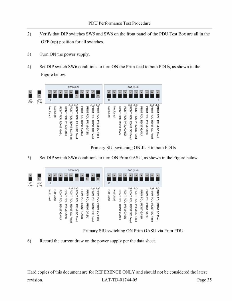
2) Verify that DIP switches SW5 and SW6 on the front panel of the PDU Test Box are all in the
OFF (up) position for all switches.
3) Turn ON the power supply.
4) Set DIP switch SW6 conditions to turn ON the Prim feed to both PDUs, as shown in the
Figure below.
UP(OFF)
Down(ON)
X
X
X XX X
XX
X X X X
PR
IM P
DU
PR
IM S
C Feed
PR
IM P
DU
RD
NT S
C Feed
PR
IM P
DU
PR
IM G
AS
U
PR
IM P
DU
RD
NT G
AS
U
RD
NT P
DU
PR
IM S
C Feed
RD
NT P
DU
RD
NT S
C Feed
RD
NT P
DU
PR
IM G
AS
U
RD
NT P
DU
RD
NT G
AS
U
Not U
sed
Not U
sed
10 1
JL-3JL-4JL-3JL-4
X XX XX XX X X X
PR
IM P
DU
PR
IM S
C Feed
PR
IM P
DU
RD
NT S
C Feed
PR
IM P
DU
PR
IM G
AS
U
PR
IM P
DU
RD
NT G
AS
U
RD
NT P
DU
PR
IM S
C Feed
RD
NT P
DU
RD
NT S
C Feed
RD
NT P
DU
PR
IM G
AS
U
RD
NT P
DU
RD
NT G
AS
U
Not U
sed
Not U
sed
10 1
JL-3JL-4JL-3JL-4
SW6 (JL-5) SW5 (JL-6)
Primary SIU switching ON JL-3 to both PDUs
5) Set DIP switch SW6 conditions to turn ON Prim GASU, as shown in the Figure below.
UP(OFF)
Down(ON)
X
X
X XX X
XX
X X X
X
PR
IM P
DU
PR
IM S
C Feed
PR
IM P
DU
RD
NT S
C Feed
PR
IM P
DU
PR
IM G
AS
U
PR
IM P
DU
RD
NT G
AS
U
RD
NT P
DU
PR
IM S
C Feed
RD
NT P
DU
RD
NT S
C Feed
RD
NT P
DU
PR
IM G
AS
U
RD
NT P
DU
RD
NT G
AS
U
Not U
sed
Not U
sed10 1
JL-3JL-4JL-3JL-4
X XX XX XX X X X
PR
IM P
DU
PR
IM S
C Feed
PR
IM P
DU
RD
NT S
C Feed
PR
IM P
DU
PR
IM G
AS
U
PR
IM P
DU
RD
NT G
AS
U
RD
NT P
DU
PR
IM S
C Feed
RD
NT P
DU
RD
NT S
C Feed
RD
NT P
DU
PR
IM G
AS
U
RD
NT P
DU
RD
NT G
AS
U
Not U
sed
Not U
sed
10 1
JL-3JL-4JL-3JL-4
SW6 (JL-5) SW5 (JL-6)
Primary SIU switching ON Prim GASU via Prim PDU
6) Record the current draw on the power supply per the data sheet.

PDU Performance Test Procedure
Hard copies of this document are for REFERENCE ONLY and should not be considered the latest
revision. LAT-TD-01744-05 Page 36
7) Open the TeraTerm program on the Windows PC in serial port mode. See the Figure below.
Tera Term Program Window, Selecting Serial Mode
8) Click on the "OK" button.
PDU Performance Test Procedure
Hard copies of this document are for REFERENCE ONLY and should not be considered the latest
revision. LAT-TD-01744-05 Page 37
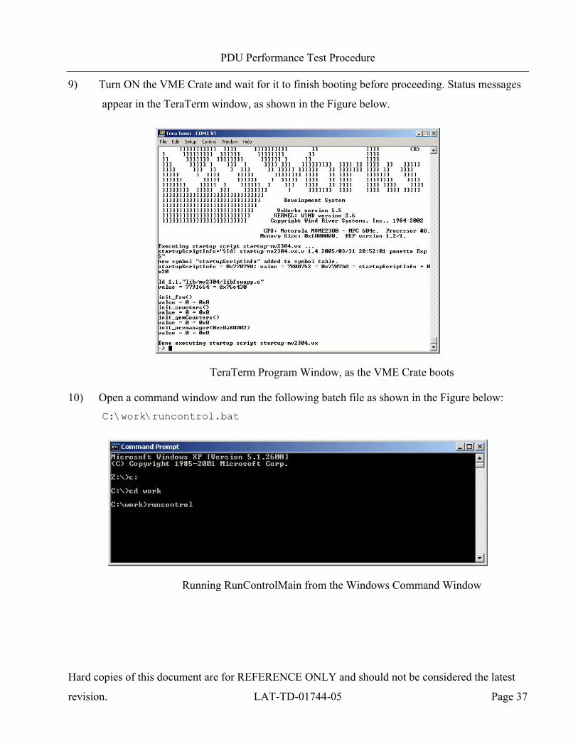
9) Turn ON the VME Crate and wait for it to finish booting before proceeding. Status messages
appear in the TeraTerm window, as shown in the Figure below.
TeraTerm Program Window, as the VME Crate boots
10) Open a command window and run the following batch file as shown in the Figure below: C:\work\runcontrol.bat
Running RunControlMain from the Windows Command Window
PDU Performance Test Procedure
Hard copies of this document are for REFERENCE ONLY and should not be considered the latest
revision. LAT-TD-01744-05 Page 38
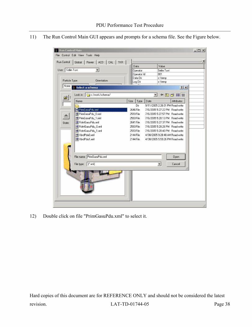
11) The Run Control Main GUI appears and prompts for a schema file. See the Figure below.
12) Double click on file "PrimGasuPdu.xml" to select it.

PDU Performance Test Procedure
Hard copies of this document are for REFERENCE ONLY and should not be considered the latest
revision. LAT-TD-01744-05 Page 39
13) In the Run Control Main window, go to the Tools menu and select ‘User Application
Browser’. See the Figure below.
Run Control Main GUI Tools Menu
PDU Performance Test Procedure
Hard copies of this document are for REFERENCE ONLY and should not be considered the latest
revision. LAT-TD-01744-05 Page 40
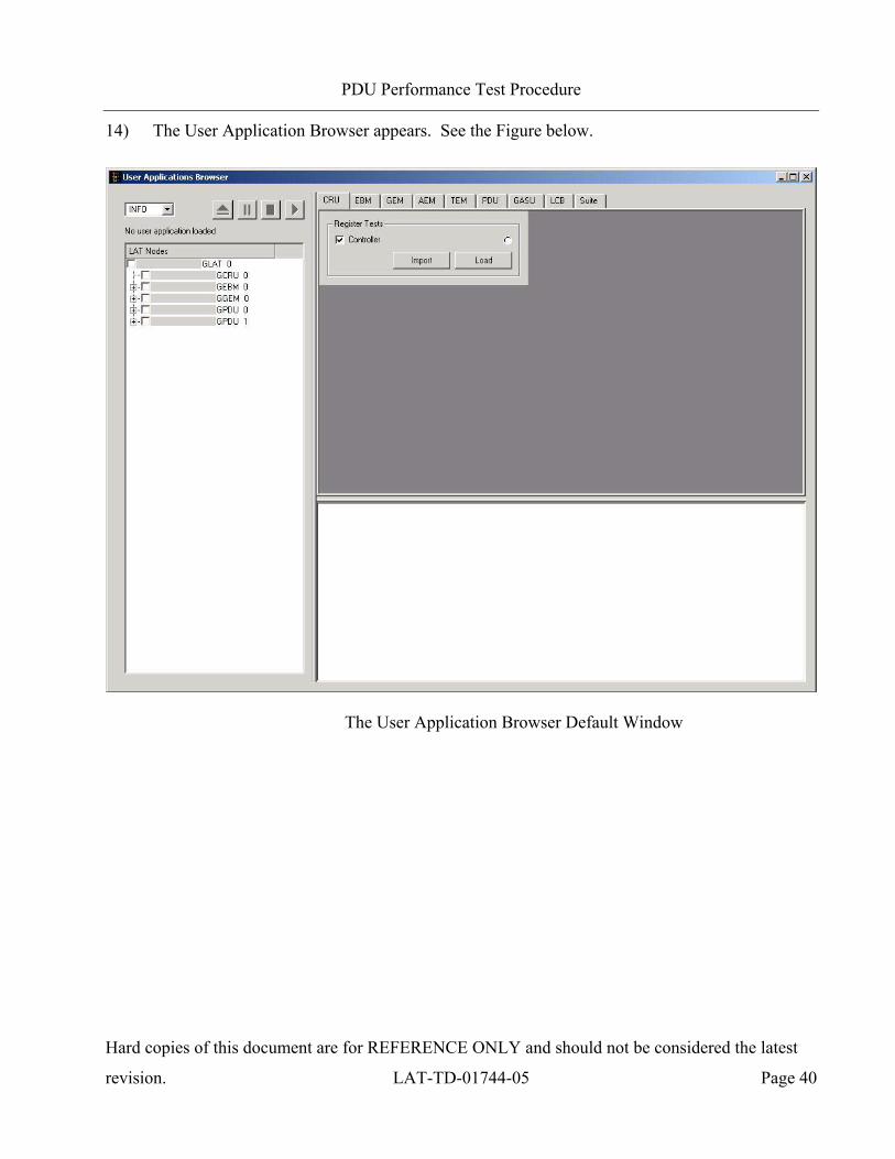
14) The User Application Browser appears. See the Figure below.
The User Application Browser Default Window
PDU Performance Test Procedure
Hard copies of this document are for REFERENCE ONLY and should not be considered the latest
revision. LAT-TD-01744-05 Page 41
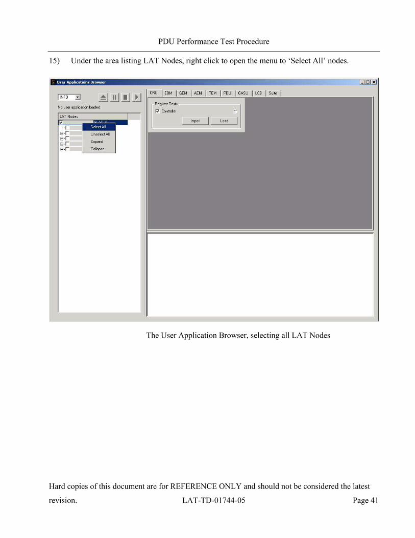
15) Under the area listing LAT Nodes, right click to open the menu to ‘Select All’ nodes.
The User Application Browser, selecting all LAT Nodes

PDU Performance Test Procedure
Hard copies of this document are for REFERENCE ONLY and should not be considered the latest
revision. LAT-TD-01744-05 Page 42
16) Under the area listing LAT Nodes, all nodes should be selected with a check box.
User Application Browser, all LAT Nodes selected
PDU Performance Test Procedure
Hard copies of this document are for REFERENCE ONLY and should not be considered the latest
revision. LAT-TD-01744-05 Page 43
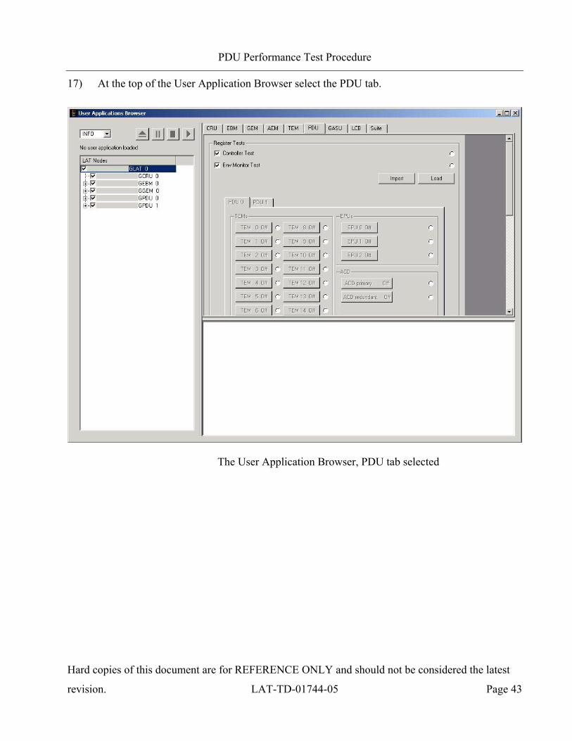
17) At the top of the User Application Browser select the PDU tab.
The User Application Browser, PDU tab selected

PDU Performance Test Procedure
Hard copies of this document are for REFERENCE ONLY and should not be considered the latest
revision. LAT-TD-01744-05 Page 44
18) Using the scroll bar at the right of the User Application Browser, scroll until the “Load”
button of the “Register Tests” section are visible.
19) Click on the “Load” button to load the Register Tests script.
20) The “Controller” and “Env Monitor” boxes should be checked. The User Applications
Browser should appear as shown below.
The User Application Browser, Register Test Setup
PDU Performance Test Procedure
Hard copies of this document are for REFERENCE ONLY and should not be considered the latest
revision. LAT-TD-01744-05 Page 45
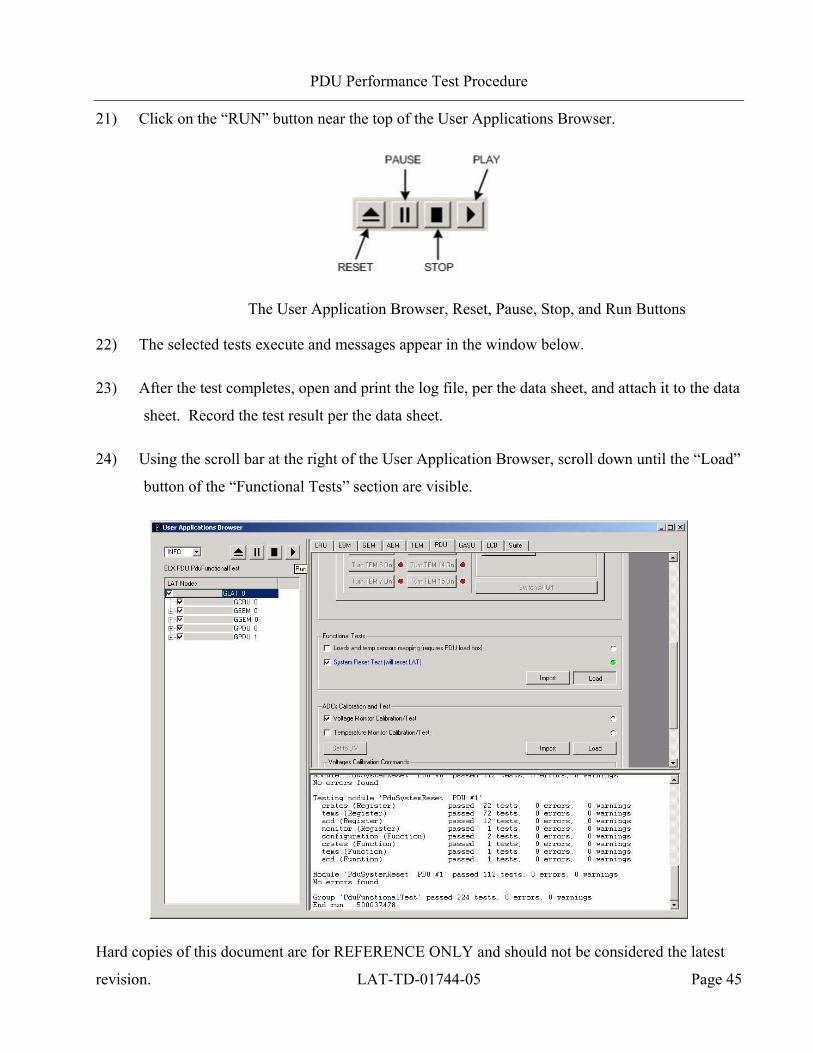
21) Click on the “RUN” button near the top of the User Applications Browser.
The User Application Browser, Reset, Pause, Stop, and Run Buttons
22) The selected tests execute and messages appear in the window below.
23) After the test completes, open and print the log file, per the data sheet, and attach it to the data
sheet. Record the test result per the data sheet.
24) Using the scroll bar at the right of the User Application Browser, scroll down until the “Load”
button of the “Functional Tests” section are visible.

PDU Performance Test Procedure
Hard copies of this document are for REFERENCE ONLY and should not be considered the latest
revision. LAT-TD-01744-05 Page 46
25) Click on the “Load” button to load the Functional Tests script.
26) Only the “System Reset Test” box should be checked.
27) Click on the “RUN” button near the top of the User Applications Browser. The selected test
executes and messages appear in the window below.
28) After the test completes, open and print the log file, per the data sheet, and attach it to the data
sheet. Record the test result per the data sheet.
29) In the main Run Control Main GUI, go to the FILE menu and select "Disconnect".
30) In the main Run Control Main GUI, go to the FILE menu and select "Select Schema". The
schema file selection window opens.
31) Double click on file "RdntGasuPdu.xml".
32) Set DIP switch SW6 conditions to turn OFF Prim GASU and turn ON the Rdnt GASU. Both
PDUs are still ON.
UP(OFF)
Down(ON)
X
X
X XX X
XX
X X
X
X
PR
IM P
DU
PR
IM S
C Feed
PR
IM P
DU
RD
NT S
C Feed
PR
IM P
DU
PR
IM G
AS
U
PR
IM P
DU
RD
NT G
AS
U
RD
NT P
DU
PR
IM S
C Feed
RD
NT P
DU
RD
NT S
C Feed
RD
NT P
DU
PR
IM G
AS
U
RD
NT P
DU
RD
NT G
AS
U
Not U
sed
Not U
sed
10 1
JL-3JL-4JL-3JL-4
X XX XX XX X X X
PR
IM P
DU
PR
IM S
C Feed
PR
IM P
DU
RD
NT S
C Feed
PR
IM P
DU
PR
IM G
AS
U
PR
IM P
DU
RD
NT G
AS
U
RD
NT P
DU
PR
IM S
C Feed
RD
NT P
DU
RD
NT S
C Feed
RD
NT P
DU
PR
IM G
AS
U
RD
NT P
DU
RD
NT G
AS
U
Not U
sed
Not U
sed
10 1
JL-3JL-4JL-3JL-4
SW6 (JL-5) SW5 (JL-6)
Primary SIU switching ON Rdnt GASU via Prim PDU
33) In the main Run Control Main GUI, go to the FILE menu and select "Connect".
34) Record the current draw on the power supply per the data sheet.
35) Repeat steps 18 through 28.

PDU Performance Test Procedure
Hard copies of this document are for REFERENCE ONLY and should not be considered the latest
revision. LAT-TD-01744-05 Page 47
36) Close the Run Control Main application.
37) Set DIP switch SW6 conditions to the OFF (up) position for all switches.
38) Turn OFF the power supply and the VME Crate.
PDU Performance Test Procedure
Hard copies of this document are for REFERENCE ONLY and should not be considered the latest
revision. LAT-TD-01744-05 Page 48
5.2.4 Load Board Mapping, Load Shedding Test (CPT)
This section is executed during CPT only. This test verifies mapping of all voltage and temperature
monitoring points.
1) The PDU Test setup should be the same as the previous section.
2) Verify that DIP switches SW5 and SW6 on the front panel of the PDU Test Box are all in the
OFF (up) position for all switches.
3) Verify that the cooling fans in the PDU Test Box are ON.
4) Turn ON the power supply and set for 28.1V. Record in the data sheet.
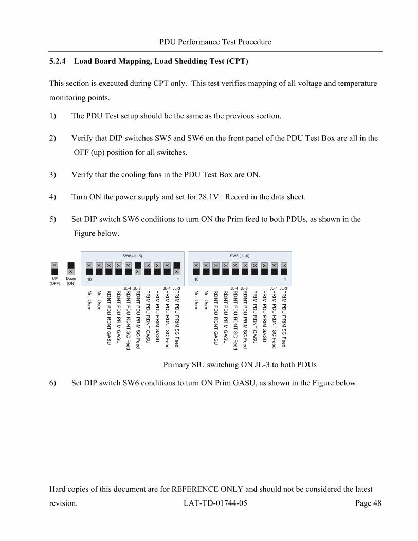
5) Set DIP switch SW6 conditions to turn ON the Prim feed to both PDUs, as shown in the
Figure below.
UP(OFF)
Down(ON)
X
X
X XX X
XX
X X X X
PR
IM P
DU
PR
IM S
C Feed
PR
IM P
DU
RD
NT S
C Feed
PR
IM P
DU
PR
IM G
AS
U
PR
IM P
DU
RD
NT G
AS
U
RD
NT P
DU
PR
IM S
C Feed
RD
NT P
DU
RD
NT S
C Feed
RD
NT P
DU
PR
IM G
AS
U
RD
NT P
DU
RD
NT G
AS
U
Not U
sed
Not U
sed
10 1
JL-3JL-4JL-3JL-4
X XX XX XX X X X
PR
IM P
DU
PR
IM S
C Feed
PR
IM P
DU
RD
NT S
C Feed
PR
IM P
DU
PR
IM G
AS
U
PR
IM P
DU
RD
NT G
AS
U
RD
NT P
DU
PR
IM S
C Feed
RD
NT P
DU
RD
NT S
C Feed
RD
NT P
DU
PR
IM G
AS
U
RD
NT P
DU
RD
NT G
AS
U
Not U
sed
Not U
sed
10 1
JL-3JL-4JL-3JL-4
SW6 (JL-5) SW5 (JL-6)
Primary SIU switching ON JL-3 to both PDUs
6) Set DIP switch SW6 conditions to turn ON Prim GASU, as shown in the Figure below.

PDU Performance Test Procedure
Hard copies of this document are for REFERENCE ONLY and should not be considered the latest
revision. LAT-TD-01744-05 Page 49
UP(OFF)
Down(ON)
X
X
X XX X
XX
X X X
X
PR
IM P
DU
PR
IM S
C Feed
PR
IM P
DU
RD
NT S
C Feed
PR
IM P
DU
PR
IM G
AS
U
PR
IM P
DU
RD
NT G
AS
U
RD
NT P
DU
PR
IM S
C Feed
RD
NT P
DU
RD
NT S
C Feed
RD
NT P
DU
PR
IM G
AS
U
RD
NT P
DU
RD
NT G
AS
U
Not U
sed
Not U
sed
10 1
JL-3JL-4JL-3JL-4
X XX XX XX X X X
PR
IM P
DU
PR
IM S
C Feed
PR
IM P
DU
RD
NT S
C Feed
PR
IM P
DU
PR
IM G
AS
U
PR
IM P
DU
RD
NT G
AS
U
RD
NT P
DU
PR
IM S
C Feed
RD
NT P
DU
RD
NT S
C Feed
RD
NT P
DU
PR
IM G
AS
U
RD
NT P
DU
RD
NT G
AS
U
Not U
sed
Not U
sed
10 1
JL-3JL-4JL-3JL-4
SW6 (JL-5) SW5 (JL-6)
Primary SIU switching ON Prim GASU via Prim PDU
7) On the Windows PC, open a TeraTerm session in serial port mode.
8) Turn ON the VME Crate and wait for it to finish booting before proceeding. Status messages
appear in the TeraTerm window.
9) Open a command window and run the following batch file: C:\work\runcontrol.bat
10) The Run Control Main GUI appears and prompts for a schema file. Double click on file
"PrimGasuPdu.xml".
11) In the Run Control Main window, go to the Tools menu and select ‘User Application
Browser’.
12) In the User Application Browser, under the area listing LAT Nodes, right click to open the
menu to ‘Select All’ nodes.
13) At the top of the User Application Browser select the PDU tab.
14) Using the scroll bar at the right of the User Application Browser, scroll until the “Load”
button of the “Functional Tests” section is visible.
15) Click on the “Load” button to load the Functional Test script.
PDU Performance Test Procedure
Hard copies of this document are for REFERENCE ONLY and should not be considered the latest
revision. LAT-TD-01744-05 Page 50
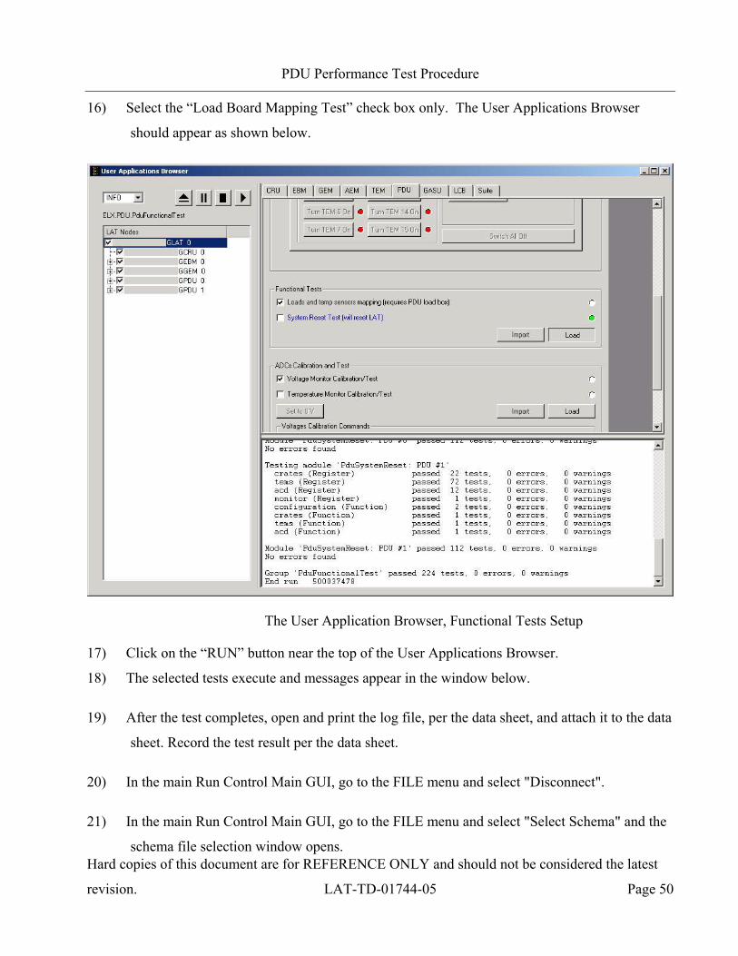
16) Select the “Load Board Mapping Test” check box only. The User Applications Browser
should appear as shown below.
The User Application Browser, Functional Tests Setup
17) Click on the “RUN” button near the top of the User Applications Browser.
18) The selected tests execute and messages appear in the window below.
19) After the test completes, open and print the log file, per the data sheet, and attach it to the data
sheet. Record the test result per the data sheet.
20) In the main Run Control Main GUI, go to the FILE menu and select "Disconnect".
21) In the main Run Control Main GUI, go to the FILE menu and select "Select Schema" and the
schema file selection window opens.

PDU Performance Test Procedure
Hard copies of this document are for REFERENCE ONLY and should not be considered the latest
revision. LAT-TD-01744-05 Page 51
22) Double click on file "RdntGasuPdu.xml".
23) Set DIP switch SW6 conditions to turn OFF Prim GASU and turn ON Rdnt GASU. Both
PDUs are still ON.
UP(OFF)
Down(ON)
X
X
X XX X
XX
X X
X
X
PR
IM P
DU
PR
IM S
C Feed
PR
IM P
DU
RD
NT S
C Feed
PR
IM P
DU
PR
IM G
AS
U
PR
IM P
DU
RD
NT G
AS
U
RD
NT P
DU
PR
IM S
C Feed
RD
NT P
DU
RD
NT S
C Feed
RD
NT P
DU
PR
IM G
AS
U
RD
NT P
DU
RD
NT G
AS
U
Not U
sed
Not U
sed
10 1
JL-3JL-4JL-3JL-4
X XX XX XX X X X
PR
IM P
DU
PR
IM S
C Feed
PR
IM P
DU
RD
NT S
C Feed
PR
IM P
DU
PR
IM G
AS
U
PR
IM P
DU
RD
NT G
AS
U
RD
NT P
DU
PR
IM S
C Feed
RD
NT P
DU
RD
NT S
C Feed
RD
NT P
DU
PR
IM G
AS
U
RD
NT P
DU
RD
NT G
AS
U
Not U
sed
Not U
sed
10 1
JL-3JL-4JL-3JL-4
SW6 (JL-5) SW5 (JL-6)
Primary SIU switching ON Rdnt GASU via Prim PDU
24) In the Run Control Main GUI, go to the FILE menu and select "Connect".
25) Repeat steps 14 through 19.
26) Scroll to the top of the User App Browser and Load the Register Tests script.
27) Use the PDU 0 power switch buttons in the GUI to turn on all TEMs and all EPUs.
28) Record the Xantrex power supply current draw.
29) Depress the red shutdown switch on the Xantrex power supply.
30) Close the Run Control Main application.
31) Set DIP switch SW6 conditions to the OFF (up) position for all switches.
32) Release the red shutdown switch on the Xantrex power supply.
33) Set DIP switch SW6 conditions to turn ON both PDUs. Then turn ON the Rdnt GASU.
PDU Performance Test Procedure
Hard copies of this document are for REFERENCE ONLY and should not be considered the latest
revision. LAT-TD-01744-05 Page 52
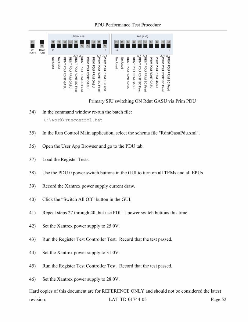
UP(OFF)
Down(ON)
X
X
X XX X
XX
X X
X
X
PR
IM P
DU
PR
IM S
C Feed
PR
IM P
DU
RD
NT S
C Feed
PR
IM P
DU
PR
IM G
AS
U
PR
IM P
DU
RD
NT G
AS
U
RD
NT P
DU
PR
IM S
C Feed
RD
NT P
DU
RD
NT S
C Feed
RD
NT P
DU
PR
IM G
AS
U
RD
NT P
DU
RD
NT G
AS
U
Not U
sed
Not U
sed
10 1
JL-3JL-4JL-3JL-4
X XX XX XX X X X
PR
IM P
DU
PR
IM S
C Feed
PR
IM P
DU
RD
NT S
C Feed
PR
IM P
DU
PR
IM G
AS
U
PR
IM P
DU
RD
NT G
AS
U
RD
NT P
DU
PR
IM S
C Feed
RD
NT P
DU
RD
NT S
C Feed
RD
NT P
DU
PR
IM G
AS
U
RD
NT P
DU
RD
NT G
AS
U
Not U
sed
Not U
sed
10 1
JL-3JL-4JL-3JL-4
SW6 (JL-5) SW5 (JL-6)
Primary SIU switching ON Rdnt GASU via Prim PDU
34) In the command window re-run the batch file: C:\work\runcontrol.bat
35) In the Run Control Main application, select the schema file "RdntGasuPdu.xml".
36) Open the User App Browser and go to the PDU tab.
37) Load the Register Tests.
38) Use the PDU 0 power switch buttons in the GUI to turn on all TEMs and all EPUs.
39) Record the Xantrex power supply current draw.
40) Click the “Switch All Off” button in the GUI.
41) Repeat steps 27 through 40, but use PDU 1 power switch buttons this time.
42) Set the Xantrex power supply to 25.0V.
43) Run the Register Test Controller Test. Record that the test passed.
44) Set the Xantrex power supply to 31.0V.
45) Run the Register Test Controller Test. Record that the test passed.
46) Set the Xantrex power supply to 28.0V.
PDU Performance Test Procedure
Hard copies of this document are for REFERENCE ONLY and should not be considered the latest
revision. LAT-TD-01744-05 Page 53
47) Close the Run Control Main application.
48) Set DIP switch SW6 conditions to the OFF (up) position for all switches.
49) Turn OFF the power supply and the VME Crate.

PDU Performance Test Procedure
Hard copies of this document are for REFERENCE ONLY and should not be considered the latest
revision. LAT-TD-01744-05 Page 54
5.2.5 Inrush Current Measurements for Each Load (CPT)
This section is executed during CPT only. This test verifies that the PDU limits inrush current for
each load.
1) Retrieve the resistance measurements across B1 and B2 of LAT-DS-05930 from the test
results of the LAT-TD-04095 PDU Test Stand Validation procedure section 5.3.10 that was
executed on the Test Stand being used. Record in the data sheet.
2) Verify the serial number (GLATxxxx) of the LAT-DS-05930 from the LAT-DS-04095 test
results, is the same as used in this procedure. Record in the data sheet.

PDU Performance Test Procedure
Hard copies of this document are for REFERENCE ONLY and should not be considered the latest
revision. LAT-TD-01744-05 Page 55
3) Configure the PDU Test setup per the steps below and referenced in the following Figure.
a) Demate LAT-DS-04309 part A from LAT-DS-04309 part BD. Record in the data
sheet.
b) Mate LAT-DS-04309 part A to LAT-DS-05930 P2. Record in the data sheet.
c) Mate LAT-DS-04309 part BD to LAT-DS-05930 P1. Record in the data sheet.
Measuring Inrush Current for Each Load Test Setup
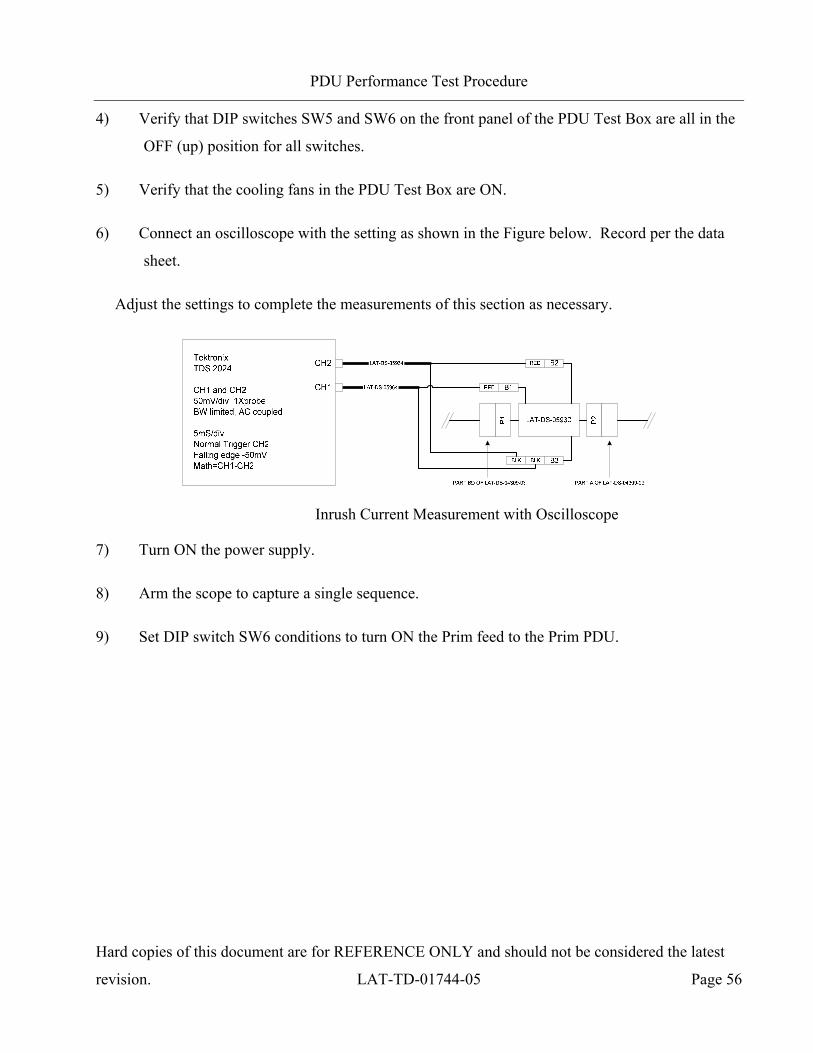
PDU Performance Test Procedure
Hard copies of this document are for REFERENCE ONLY and should not be considered the latest
revision. LAT-TD-01744-05 Page 56
4) Verify that DIP switches SW5 and SW6 on the front panel of the PDU Test Box are all in the
OFF (up) position for all switches.
5) Verify that the cooling fans in the PDU Test Box are ON.
6) Connect an oscilloscope with the setting as shown in the Figure below. Record per the data
sheet.
Adjust the settings to complete the measurements of this section as necessary.
Inrush Current Measurement with Oscilloscope
7) Turn ON the power supply.
8) Arm the scope to capture a single sequence.
9) Set DIP switch SW6 conditions to turn ON the Prim feed to the Prim PDU.
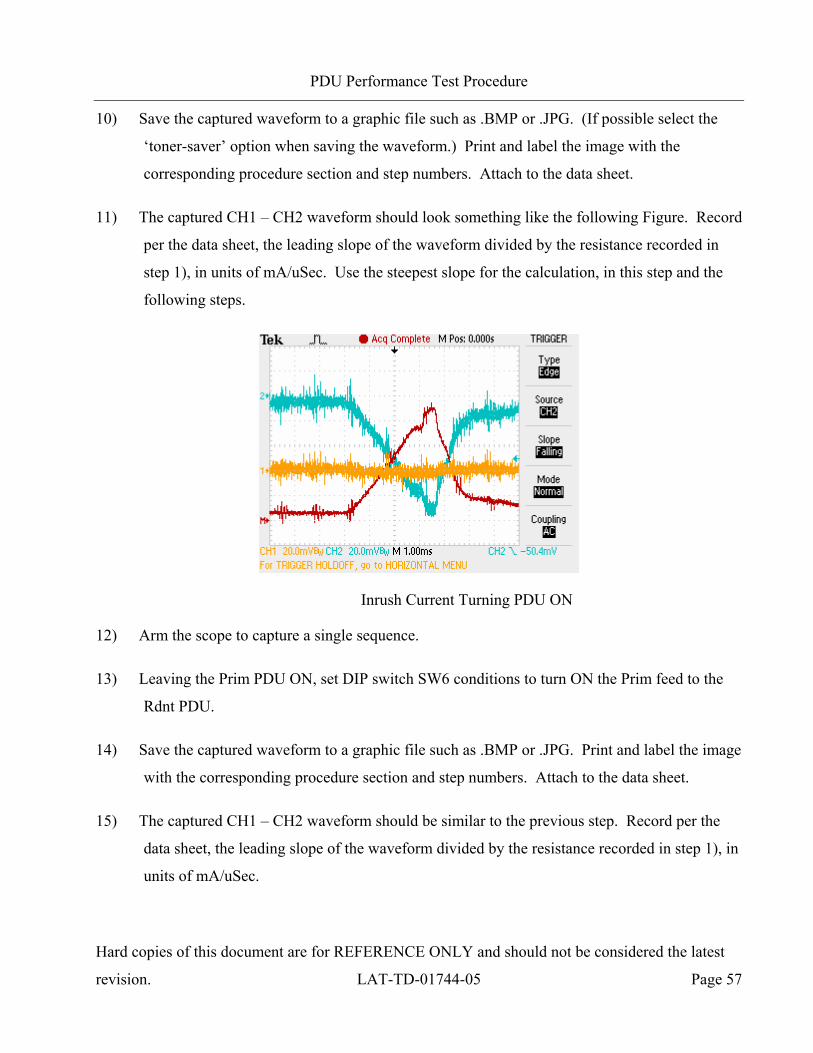
PDU Performance Test Procedure
Hard copies of this document are for REFERENCE ONLY and should not be considered the latest
revision. LAT-TD-01744-05 Page 57
10) Save the captured waveform to a graphic file such as .BMP or .JPG. (If possible select the
‘toner-saver’ option when saving the waveform.) Print and label the image with the
corresponding procedure section and step numbers. Attach to the data sheet.
11) The captured CH1 – CH2 waveform should look something like the following Figure. Record
per the data sheet, the leading slope of the waveform divided by the resistance recorded in
step 1), in units of mA/uSec. Use the steepest slope for the calculation, in this step and the
following steps.
Inrush Current Turning PDU ON
12) Arm the scope to capture a single sequence.
13) Leaving the Prim PDU ON, set DIP switch SW6 conditions to turn ON the Prim feed to the
Rdnt PDU.
14) Save the captured waveform to a graphic file such as .BMP or .JPG. Print and label the image
with the corresponding procedure section and step numbers. Attach to the data sheet.
15) The captured CH1 – CH2 waveform should be similar to the previous step. Record per the
data sheet, the leading slope of the waveform divided by the resistance recorded in step 1), in
units of mA/uSec.

PDU Performance Test Procedure
Hard copies of this document are for REFERENCE ONLY and should not be considered the latest
revision. LAT-TD-01744-05 Page 58
16) Arm the scope to capture a single sequence.
17) Set DIP switch SW6 conditions to turn ON the Prim GASU using the Prim PDU.
18) Save the captured waveform to a graphic file such as .BMP or .JPG. Print and label the image
with the corresponding procedure section and step numbers. Attach to the data sheet.
19) The captured CH1 – CH2 waveform should look something like the following Figure. Record
per the data sheet, the leading slope of the waveform divided by the resistance recorded in
step 1), in units of mA/uSec.
Inrush Current Turning GASU ON
20) Set DIP switch SW6 conditions to turn OFF Prim GASU. Leave both PDUs ON.
21) Arm the scope to capture a single sequence.
22) Set DIP switch SW6 conditions to turn ON the Rdnt GASU using the Prim PDU.
PDU Performance Test Procedure
Hard copies of this document are for REFERENCE ONLY and should not be considered the latest
revision. LAT-TD-01744-05 Page 59
23) Save the captured waveform to a graphic file such as .BMP or .JPG. Print and label the image
with the corresponding procedure section and step numbers. Attach to the data sheet.
24) The captured CH1 – CH2 waveform should be similar to the previous step. Record per the
data sheet, the leading slope of the waveform divided by the resistance recorded in step 1), in
units of mA/uSec.
25) Set DIP switch SW6 conditions to turn OFF Rdnt GASU. Leave both PDUs ON.
26) Arm the scope to capture a single sequence.
27) Set DIP switch SW6 conditions to turn ON the Prim GASU using the Rdnt PDU.
28) Save the captured waveform to a graphic file such as .BMP or .JPG. Print and label the image
with the corresponding procedure section and step numbers. Attach to the data sheet.
29) The captured CH1 – CH2 waveform should be similar to the previous step. Record per the
data sheet, the leading slope of the waveform divided by the resistance recorded in step 1), in
units of mA/uSec.
30) Set DIP switch SW6 conditions to turn OFF Prim GASU. Leave both PDUs ON.
31) Arm the scope to capture a single sequence.
32) Set DIP switch SW6 conditions to turn ON the Rdnt GASU using the Rdnt PDU.
33) Save the captured waveform to a graphic file such as .BMP or .JPG. Print and label the image
with the corresponding procedure section and step numbers. Attach to the data sheet.
34) The captured CH1 – CH2 waveform should be similar to the previous step. Record per the
data sheet, the leading slope of the waveform divided by the resistance recorded in step 1), in
units of mA/uSec.
PDU Performance Test Procedure
Hard copies of this document are for REFERENCE ONLY and should not be considered the latest
revision. LAT-TD-01744-05 Page 60
35) On the Windows PC, open a TeraTerm session in serial port mode.
36) Turn ON the VME Crate and wait for it to finish booting before proceeding. Status messages
appear in the TeraTerm window.
37) Open a command window and run the following batch file: C:\work\runcontrol.bat
38) The Run Control Main GUI appears and prompts for a schema file. Double click on file
"RdntGasuPdu.xml".
39) In the Run Control Main window, go to the Tools menu and select ‘User Application
Browser’.
40) In the User Application Browser, under the area listing LAT Nodes, right click to open the
menu to ‘Select All’ nodes.
41) At the top of the User Application Browser select the PDU tab.
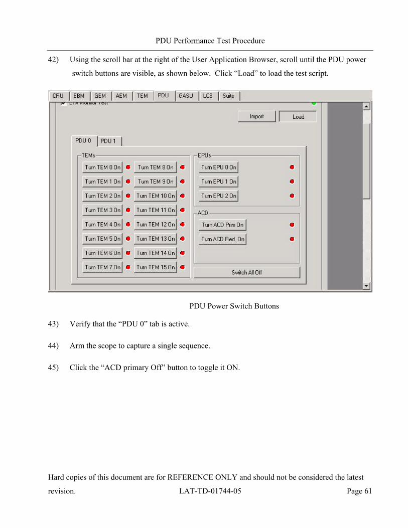
PDU Performance Test Procedure
Hard copies of this document are for REFERENCE ONLY and should not be considered the latest
revision. LAT-TD-01744-05 Page 61
42) Using the scroll bar at the right of the User Application Browser, scroll until the PDU power
switch buttons are visible, as shown below. Click “Load” to load the test script.
PDU Power Switch Buttons
43) Verify that the “PDU 0” tab is active.
44) Arm the scope to capture a single sequence.
45) Click the “ACD primary Off” button to toggle it ON.
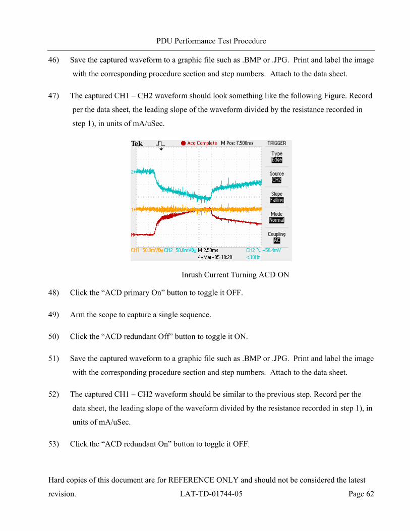
PDU Performance Test Procedure
Hard copies of this document are for REFERENCE ONLY and should not be considered the latest
revision. LAT-TD-01744-05 Page 62
46) Save the captured waveform to a graphic file such as .BMP or .JPG. Print and label the image
with the corresponding procedure section and step numbers. Attach to the data sheet.
47) The captured CH1 – CH2 waveform should look something like the following Figure. Record
per the data sheet, the leading slope of the waveform divided by the resistance recorded in
step 1), in units of mA/uSec.
Inrush Current Turning ACD ON
48) Click the “ACD primary On” button to toggle it OFF.
49) Arm the scope to capture a single sequence.
50) Click the “ACD redundant Off” button to toggle it ON.
51) Save the captured waveform to a graphic file such as .BMP or .JPG. Print and label the image
with the corresponding procedure section and step numbers. Attach to the data sheet.
52) The captured CH1 – CH2 waveform should be similar to the previous step. Record per the
data sheet, the leading slope of the waveform divided by the resistance recorded in step 1), in
units of mA/uSec.
53) Click the “ACD redundant On” button to toggle it OFF.
PDU Performance Test Procedure
Hard copies of this document are for REFERENCE ONLY and should not be considered the latest
revision. LAT-TD-01744-05 Page 63
54) Arm the scope to capture a single sequence.
55) Click the “EPU 0 Off” button to toggle it ON.
56) Save the captured waveform to a graphic file such as .BMP or .JPG. Print and label the image
with the corresponding procedure section and step numbers. Attach to the data sheet.
57) The captured CH1 – CH2 waveform should be similar to the previous step. Record per the
data sheet, the leading slope of the waveform divided by the resistance recorded in step 1), in
units of mA/uSec.
58) Click the “EPU 0 ON” button to toggle it OFF.
59) Repeat the sequence of arming the scope, turning ON the remaining equipment EPU or TEM
ONE at a time, saving and printing the waveform, recording the inrush current per the data
sheet, and turning OFF the EPU or TEM (steps 53 through 58, for example). Sequence
through each EPU and TEM per the data sheet. Turn ON only ONE EPU or TEM at a time
because the sense resistor at the input to the PDU cannot handle higher currents. It may not
be necessary to save and print the waveform for every EPU and TEM since these plots
should be virtually identical.
60) Click the “Switch All Off” button to turn everything OFF.
61) Click the “PDU 1” tab to switch context to the Rdnt PDU.
62) Repeat the sequence of arming the scope, turning ON each ACD, EPU, or TEM one at a
time, saving and printing the waveform, recording the inrush current per the data sheet, and
turning OFF the ACD, EPU or TEM. Sequence through each ACD, EPU, and TEM per the
data sheet. Turn ON only ONE ACD, EPU, or TEM at a time, because the sense resistor at
the input to the PDU cannot handle higher currents.
63) Click the “Switch All Off” button to turn everything OFF.
PDU Performance Test Procedure
Hard copies of this document are for REFERENCE ONLY and should not be considered the latest
revision. LAT-TD-01744-05 Page 64
64) Close the Run Control Main application.
65) Set SW6 DIP switch conditions to the OFF (up) position for all switches.
66) Turn OFF the power supply and the VME Crate.
67) Remove LAT-DS-05930 from the Test Setup:
a) Demate LAT-DS-04309 part A from LAT-DS-05930 P2. Record in the data sheet.
b) Demate LAT-DS-04309 part BD from LAT-DS-05930 P1. Record in the data sheet.
c) Mate LAT-DS-04309 part A to LAT-DS-04309 part BD. Record in the data sheet.

PDU Performance Test Procedure
Hard copies of this document are for REFERENCE ONLY and should not be considered the latest
revision. LAT-TD-01744-05 Page 65
5.2.6 Testing Overcurrent of PDU for GASU, ACD, TEM and EPU Circuits (CPT)
This section is executed during CPT only. This test verifies that the PDU overcurrent circuit for
each load switch is functional.
5.2.6.1 Initial Test Setup
1) Verify the configuration the PDU Test setup per referenced in the following Figure. Record in
the data sheet.
Validating Overcurrent Circuits Test Setup
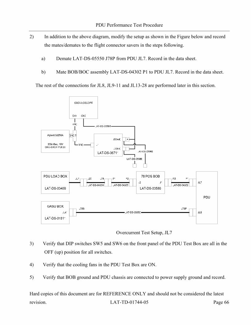
PDU Performance Test Procedure
Hard copies of this document are for REFERENCE ONLY and should not be considered the latest
revision. LAT-TD-01744-05 Page 66
2) In addition to the above diagram, modify the setup as shown in the Figure below and record
the mates/demates to the flight connector savers in the steps following.
a) Demate LAT-DS-05550 J78P from PDU JL7. Record in the data sheet.
b) Mate BOB/BOC assembly LAT-DS-04302 P1 to PDU JL7. Record in the data sheet.
The rest of the connections for JL8, JL9-11 and JL13-28 are performed later in this section.
Overcurrent Test Setup, JL7
3) Verify that DIP switches SW5 and SW6 on the front panel of the PDU Test Box are all in the
OFF (up) position for all switches.
4) Verify that the cooling fans in the PDU Test Box are ON.
5) Verify that BOB ground and PDU chassis are connected to power supply ground and record.

PDU Performance Test Procedure
Hard copies of this document are for REFERENCE ONLY and should not be considered the latest
revision. LAT-TD-01744-05 Page 67
6) Verify that all of the BOB shorting plugs are inserted so that it is configured in “through”
mode. Record in the data sheet.
7) Verify the power supply is set for 28.0V.
NOTE: In the following subsections, the operator must make multiple copies of data sheets
and fill in the blanks for the item being tested. The groups Prim GASU/ACD and
Rdnt GASU/ACD have common data sheets. The groups TEM0-1, TEM2-3, TEM4-
5, TEM6-7, TEM8-9, TEM10-11, TEM12-13, and TEM14-15 have common data
sheets.
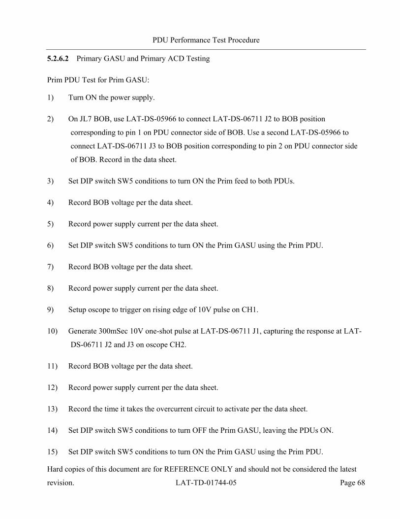
PDU Performance Test Procedure
Hard copies of this document are for REFERENCE ONLY and should not be considered the latest
revision. LAT-TD-01744-05 Page 68
5.2.6.2 Primary GASU and Primary ACD Testing
Prim PDU Test for Prim GASU:
1) Turn ON the power supply.
2) On JL7 BOB, use LAT-DS-05966 to connect LAT-DS-06711 J2 to BOB position
corresponding to pin 1 on PDU connector side of BOB. Use a second LAT-DS-05966 to
connect LAT-DS-06711 J3 to BOB position corresponding to pin 2 on PDU connector side
of BOB. Record in the data sheet.
3) Set DIP switch SW5 conditions to turn ON the Prim feed to both PDUs.
4) Record BOB voltage per the data sheet.
5) Record power supply current per the data sheet.
6) Set DIP switch SW5 conditions to turn ON the Prim GASU using the Prim PDU.
7) Record BOB voltage per the data sheet.
8) Record power supply current per the data sheet.
9) Setup oscope to trigger on rising edge of 10V pulse on CH1.
10) Generate 300mSec 10V one-shot pulse at LAT-DS-06711 J1, capturing the response at LAT-
DS-06711 J2 and J3 on oscope CH2.
11) Record BOB voltage per the data sheet.
12) Record power supply current per the data sheet.
13) Record the time it takes the overcurrent circuit to activate per the data sheet.
14) Set DIP switch SW5 conditions to turn OFF the Prim GASU, leaving the PDUs ON.
15) Set DIP switch SW5 conditions to turn ON the Prim GASU using the Prim PDU.
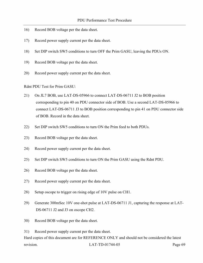
PDU Performance Test Procedure
Hard copies of this document are for REFERENCE ONLY and should not be considered the latest
revision. LAT-TD-01744-05 Page 69
16) Record BOB voltage per the data sheet.
17) Record power supply current per the data sheet.
18) Set DIP switch SW5 conditions to turn OFF the Prim GASU, leaving the PDUs ON.
19) Record BOB voltage per the data sheet.
20) Record power supply current per the data sheet.
Rdnt PDU Test for Prim GASU:
21) On JL7 BOB, use LAT-DS-05966 to connect LAT-DS-06711 J2 to BOB position
corresponding to pin 40 on PDU connector side of BOB. Use a second LAT-DS-05966 to
connect LAT-DS-06711 J3 to BOB position corresponding to pin 41 on PDU connector side
of BOB. Record in the data sheet.
22) Set DIP switch SW5 conditions to turn ON the Prim feed to both PDUs.
23) Record BOB voltage per the data sheet.
24) Record power supply current per the data sheet.
25) Set DIP switch SW5 conditions to turn ON the Prim GASU using the Rdnt PDU.
26) Record BOB voltage per the data sheet.
27) Record power supply current per the data sheet.
28) Setup oscope to trigger on rising edge of 10V pulse on CH1.
29) Generate 300mSec 10V one-shot pulse at LAT-DS-06711 J1, capturing the response at LAT-
DS-06711 J2 and J3 on oscope CH2.
30) Record BOB voltage per the data sheet.
31) Record power supply current per the data sheet.
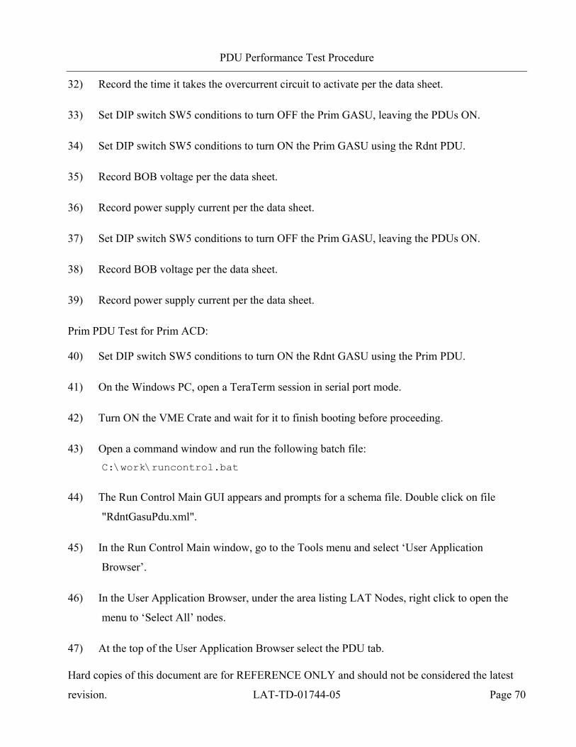
PDU Performance Test Procedure
Hard copies of this document are for REFERENCE ONLY and should not be considered the latest
revision. LAT-TD-01744-05 Page 70
32) Record the time it takes the overcurrent circuit to activate per the data sheet.
33) Set DIP switch SW5 conditions to turn OFF the Prim GASU, leaving the PDUs ON.
34) Set DIP switch SW5 conditions to turn ON the Prim GASU using the Rdnt PDU.
35) Record BOB voltage per the data sheet.
36) Record power supply current per the data sheet.
37) Set DIP switch SW5 conditions to turn OFF the Prim GASU, leaving the PDUs ON.
38) Record BOB voltage per the data sheet.
39) Record power supply current per the data sheet.
Prim PDU Test for Prim ACD:
40) Set DIP switch SW5 conditions to turn ON the Rdnt GASU using the Prim PDU.
41) On the Windows PC, open a TeraTerm session in serial port mode.
42) Turn ON the VME Crate and wait for it to finish booting before proceeding.
43) Open a command window and run the following batch file: C:\work\runcontrol.bat
44) The Run Control Main GUI appears and prompts for a schema file. Double click on file
"RdntGasuPdu.xml".
45) In the Run Control Main window, go to the Tools menu and select ‘User Application
Browser’.
46) In the User Application Browser, under the area listing LAT Nodes, right click to open the
menu to ‘Select All’ nodes.
47) At the top of the User Application Browser select the PDU tab.

PDU Performance Test Procedure
Hard copies of this document are for REFERENCE ONLY and should not be considered the latest
revision. LAT-TD-01744-05 Page 71
48) Using the scroll bar at the right of the User Application Browser, scroll down until the PDU
power switch buttons are visible. Click “Load” to load the test script.
49) In the User Application Browser, select the “PDU 0” tab to make it active.
50) On JL7 BOB, use LAT-DS-05966 to connect LAT-DS-06711 J2 to BOB position
corresponding to pin 21 on PDU connector side of BOB. Use a second LAT-DS-05966 to
connect LAT-DS-06711 J3 to BOB position corresponding to pin 22 on PDU connector side
of BOB. Record in the data sheet.
51) Record BOB voltage per the data sheet.
52) Record power supply current per the data sheet.
53) Turn ON ACD primary with PDU 0.
54) Record BOB voltage per the data sheet.
55) Record power supply current per the data sheet.
56) Setup oscope to trigger on rising edge of 10V pulse on CH1.
57) Generate 300mSec 10V one-shot pulse at LAT-DS-06711 J1, capturing the response at LAT-
DS-06711 J2 and J3 on oscope CH2.
58) Record BOB voltage per the data sheet.
59) Record power supply current per the data sheet.
60) Record the time it takes the overcurrent circuit to activate per the data sheet.
61) Click on the “Switch All Off” button to turn all loads OFF.
62) Turn ON ACD primary with PDU 0.
63) Record BOB voltage per the data sheet.
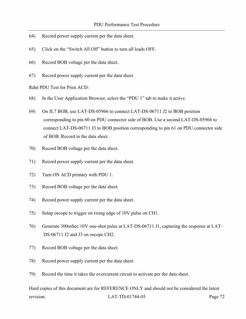
PDU Performance Test Procedure
Hard copies of this document are for REFERENCE ONLY and should not be considered the latest
revision. LAT-TD-01744-05 Page 72
64) Record power supply current per the data sheet.
65) Click on the “Switch All Off” button to turn all loads OFF.
66) Record BOB voltage per the data sheet.
67) Record power supply current per the data sheet.
Rdnt PDU Test for Prim ACD:
68) In the User Application Browser, select the “PDU 1” tab to make it active.
69) On JL7 BOB, use LAT-DS-05966 to connect LAT-DS-06711 J2 to BOB position
corresponding to pin 60 on PDU connector side of BOB. Use a second LAT-DS-05966 to
connect LAT-DS-06711 J3 to BOB position corresponding to pin 61 on PDU connector side
of BOB. Record in the data sheet.
70) Record BOB voltage per the data sheet.
71) Record power supply current per the data sheet.
72) Turn ON ACD primary with PDU 1.
73) Record BOB voltage per the data sheet.
74) Record power supply current per the data sheet.
75) Setup oscope to trigger on rising edge of 10V pulse on CH1.
76) Generate 300mSec 10V one-shot pulse at LAT-DS-06711 J1, capturing the response at LAT-
DS-06711 J2 and J3 on oscope CH2.
77) Record BOB voltage per the data sheet.
78) Record power supply current per the data sheet.
79) Record the time it takes the overcurrent circuit to activate per the data sheet.
PDU Performance Test Procedure
Hard copies of this document are for REFERENCE ONLY and should not be considered the latest
revision. LAT-TD-01744-05 Page 73
80) Click on the “Switch All Off” button to turn all loads OFF.
81) Turn ON ACD primary with PDU 1.
82) Record BOB voltage per the data sheet.
83) Record power supply current per the data sheet.
84) Click on the “Switch All Off” button to turn all loads OFF.
85) Record BOB voltage per the data sheet.
86) Record power supply current per the data sheet.
87) Close the Run Control application.
88) Set DIP switch SW5 conditions to the OFF (up) position for all switches.
89) Turn OFF the power supply and the VME Crate.
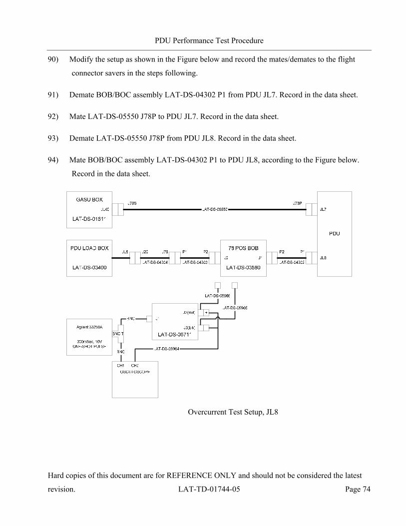
PDU Performance Test Procedure
Hard copies of this document are for REFERENCE ONLY and should not be considered the latest
revision. LAT-TD-01744-05 Page 74
90) Modify the setup as shown in the Figure below and record the mates/demates to the flight
connector savers in the steps following.
91) Demate BOB/BOC assembly LAT-DS-04302 P1 from PDU JL7. Record in the data sheet.
92) Mate LAT-DS-05550 J78P to PDU JL7. Record in the data sheet.
93) Demate LAT-DS-05550 J78P from PDU JL8. Record in the data sheet.
94) Mate BOB/BOC assembly LAT-DS-04302 P1 to PDU JL8, according to the Figure below.
Record in the data sheet.
Overcurrent Test Setup, JL8
PDU Performance Test Procedure
Hard copies of this document are for REFERENCE ONLY and should not be considered the latest
revision. LAT-TD-01744-05 Page 75
5.2.6.3 Redundant GASU and Redundant ACD Testing
Prim PDU Test for Rdnt GASU:
1) Turn ON the power supply.
2) On JL8 BOB, use LAT-DS-05966 to connect LAT-DS-06711 J2 to BOB position
corresponding to pin 1 on PDU connector side of BOB. Use a second LAT-DS-05966 to
connect LAT-DS-06711 J3 to BOB position corresponding to pin 2 on PDU connector side
of BOB. Record in the data sheet.
3) Set DIP switch SW5 conditions to turn ON the Prim feed to both PDUs.
4) Record BOB voltage per the data sheet.
5) Record power supply current per the data sheet.
6) Set DIP switch SW5 conditions to turn ON the Rdnt GASU using the Prim PDU.
7) Record BOB voltage per the data sheet.
8) Record power supply current per the data sheet.
9) Setup oscope to trigger on rising edge of 10V pulse on CH1.
10) Generate 300mSec 10V one-shot pulse at LAT-DS-06711 J1, capturing the response at LAT-
DS-06711 J2 and J3 on oscope CH2.
11) Record BOB voltage per the data sheet.
12) Record power supply current per the data sheet.
13) Record the time it takes the overcurrent circuit to activate per the data sheet.
14) Set DIP switch SW5 conditions to turn OFF the Rdnt GASU, leaving the PDUs ON.
15) Set DIP switch SW5 conditions to turn ON the Rdnt GASU using the Prim PDU.
PDU Performance Test Procedure
Hard copies of this document are for REFERENCE ONLY and should not be considered the latest
revision. LAT-TD-01744-05 Page 76
16) Record BOB voltage per the data sheet.
17) Record power supply current per the data sheet.
18) Set DIP switch SW5 conditions to turn OFF the Rdnt GASU, leaving the PDUs ON.
19) Record BOB voltage per the data sheet.
20) Record power supply current per the data sheet.
Rdnt PDU Test for Rdnt GASU:
21) On JL8 BOB, use LAT-DS-05966 to connect LAT-DS-06711 J2 to BOB position
corresponding to pin 40 on PDU connector side of BOB. Use a second LAT-DS-05966 to
connect LAT-DS-06711 J3 to BOB position corresponding to pin 41 on PDU connector side
of BOB. Record in the data sheet.
22) Set DIP switch SW5 conditions to turn ON the Prim feed to both PDUs.
23) Record BOB voltage per the data sheet.
24) Record power supply current per the data sheet.
25) Set DIP switch SW5 conditions to turn ON the Rdnt GASU using the Rdnt PDU.
26) Record BOB voltage per the data sheet.
27) Record power supply current per the data sheet.
28) Setup oscope to trigger on rising edge of 10V pulse on CH1.
29) Generate 300mSec 10V one-shot pulse at LAT-DS-06711 J1, capturing the response at LAT-
DS-06711 J2 and J3 on oscope CH2.
30) Record BOB voltage per the data sheet.
31) Record power supply current per the data sheet.

PDU Performance Test Procedure
Hard copies of this document are for REFERENCE ONLY and should not be considered the latest
revision. LAT-TD-01744-05 Page 77
32) Record the time it takes the overcurrent circuit to activate per the data sheet.
33) Set DIP switch SW5 conditions to turn OFF the Rdnt GASU, leaving the PDUs ON.
34) Set DIP switch SW5 conditions to turn ON the Rdnt GASU using the Rdnt PDU.
35) Record BOB voltage per the data sheet.
36) Record power supply current per the data sheet.
37) Set DIP switch SW5 conditions to turn OFF the Rdnt GASU, leaving the PDUs ON.
38) Record BOB voltage per the data sheet.
39) Record power supply current per the data sheet.
Prim PDU Test for Rdnt ACD:
40) Set DIP switch SW5 conditions to turn ON the Prim GASU using the Prim PDU.
41) On the Windows PC, open a TeraTerm session in serial port mode
42) Turn ON the VME Crate and wait for it to finish booting before proceeding.
43) Open a command window and run the following batch file: C:\work\runcontrol.bat
44) The Run Control Main GUI appears and prompts for a schema file. Double click on file
"PrimGasuPdu.xml".
45) In the Run Control Main window, go to the Tools menu and select ‘User Application
Browser’.
46) In the User Application Browser, under the area listing LAT Nodes, right click to open the
menu to ‘Select All’ nodes.
47) At the top of the User Application Browser select the PDU tab.
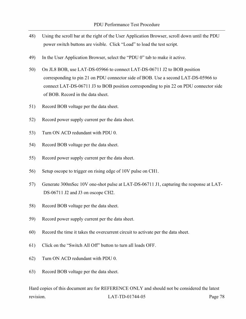
PDU Performance Test Procedure
Hard copies of this document are for REFERENCE ONLY and should not be considered the latest
revision. LAT-TD-01744-05 Page 78
48) Using the scroll bar at the right of the User Application Browser, scroll down until the PDU
power switch buttons are visible. Click “Load” to load the test script.
49) In the User Application Browser, select the “PDU 0” tab to make it active.
50) On JL8 BOB, use LAT-DS-05966 to connect LAT-DS-06711 J2 to BOB position
corresponding to pin 21 on PDU connector side of BOB. Use a second LAT-DS-05966 to
connect LAT-DS-06711 J3 to BOB position corresponding to pin 22 on PDU connector side
of BOB. Record in the data sheet.
51) Record BOB voltage per the data sheet.
52) Record power supply current per the data sheet.
53) Turn ON ACD redundant with PDU 0.
54) Record BOB voltage per the data sheet.
55) Record power supply current per the data sheet.
56) Setup oscope to trigger on rising edge of 10V pulse on CH1.
57) Generate 300mSec 10V one-shot pulse at LAT-DS-06711 J1, capturing the response at LAT-
DS-06711 J2 and J3 on oscope CH2.
58) Record BOB voltage per the data sheet.
59) Record power supply current per the data sheet.
60) Record the time it takes the overcurrent circuit to activate per the data sheet.
61) Click on the “Switch All Off” button to turn all loads OFF.
62) Turn ON ACD redundant with PDU 0.
63) Record BOB voltage per the data sheet.
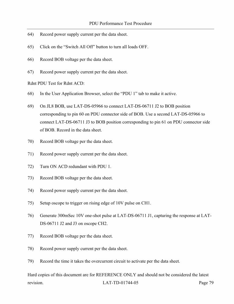
PDU Performance Test Procedure
Hard copies of this document are for REFERENCE ONLY and should not be considered the latest
revision. LAT-TD-01744-05 Page 79
64) Record power supply current per the data sheet.
65) Click on the “Switch All Off” button to turn all loads OFF.
66) Record BOB voltage per the data sheet.
67) Record power supply current per the data sheet.
Rdnt PDU Test for Rdnt ACD:
68) In the User Application Browser, select the “PDU 1” tab to make it active.
69) On JL8 BOB, use LAT-DS-05966 to connect LAT-DS-06711 J2 to BOB position
corresponding to pin 60 on PDU connector side of BOB. Use a second LAT-DS-05966 to
connect LAT-DS-06711 J3 to BOB position corresponding to pin 61 on PDU connector side
of BOB. Record in the data sheet.
70) Record BOB voltage per the data sheet.
71) Record power supply current per the data sheet.
72) Turn ON ACD redundant with PDU 1.
73) Record BOB voltage per the data sheet.
74) Record power supply current per the data sheet.
75) Setup oscope to trigger on rising edge of 10V pulse on CH1.
76) Generate 300mSec 10V one-shot pulse at LAT-DS-06711 J1, capturing the response at LAT-
DS-06711 J2 and J3 on oscope CH2.
77) Record BOB voltage per the data sheet.
78) Record power supply current per the data sheet.
79) Record the time it takes the overcurrent circuit to activate per the data sheet.
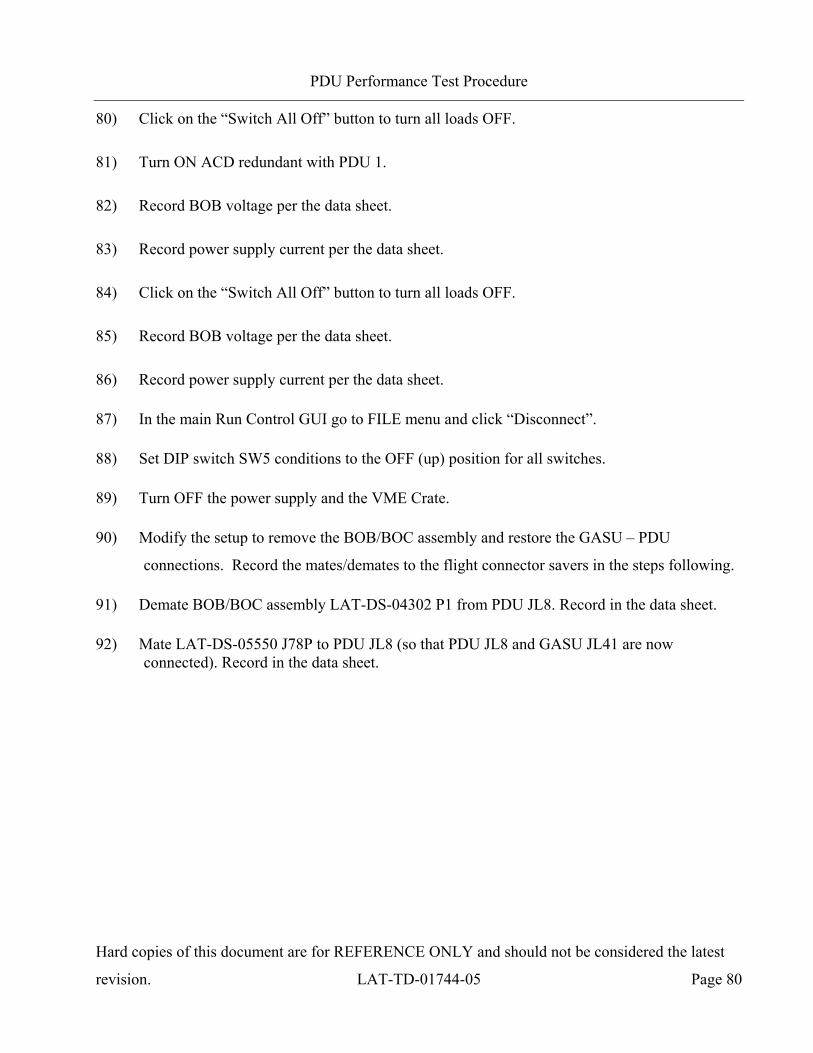
PDU Performance Test Procedure
Hard copies of this document are for REFERENCE ONLY and should not be considered the latest
revision. LAT-TD-01744-05 Page 80
80) Click on the “Switch All Off” button to turn all loads OFF.
81) Turn ON ACD redundant with PDU 1.
82) Record BOB voltage per the data sheet.
83) Record power supply current per the data sheet.
84) Click on the “Switch All Off” button to turn all loads OFF.
85) Record BOB voltage per the data sheet.
86) Record power supply current per the data sheet.
87) In the main Run Control GUI go to FILE menu and click “Disconnect”.
88) Set DIP switch SW5 conditions to the OFF (up) position for all switches.
89) Turn OFF the power supply and the VME Crate.
90) Modify the setup to remove the BOB/BOC assembly and restore the GASU – PDU
connections. Record the mates/demates to the flight connector savers in the steps following.
91) Demate BOB/BOC assembly LAT-DS-04302 P1 from PDU JL8. Record in the data sheet.
92) Mate LAT-DS-05550 J78P to PDU JL8 (so that PDU JL8 and GASU JL41 are now connected). Record in the data sheet.

PDU Performance Test Procedure
Hard copies of this document are for REFERENCE ONLY and should not be considered the latest
revision. LAT-TD-01744-05 Page 81
5.2.6.4 TEM 0-1 Testing
1) Modify the setup as shown in the Figure below and record the mates/demates to the flight
connector savers in the steps following.
a) Demate LAT-DS-04308 P1 from PDU JL13. Record in the data sheet.
b) Mate BOB/BOC assembly LAT-DS-04298 P1 to PDU JL13. Record in the data sheet.
c) Demate LAT-DS-04308 P1 from PDU JL14. Record in the data sheet.
d) Mate BOB/BOC assembly LAT-DS-04298 P1 to PDU JL14. Record in the data sheet.
e) Insert all shorting plugs on the two BOBs and record.
Overcurrent Test Setup, JL13 and JL14
2) Turn ON the power supply.

PDU Performance Test Procedure
Hard copies of this document are for REFERENCE ONLY and should not be considered the latest
revision. LAT-TD-01744-05 Page 82
3) Set DIP switch SW5 conditions to turn ON the Prim feed to both PDUs.
4) Set DIP switch SW5 conditions to turn ON the Prim GASU using the Prim PDU.
5) Turn ON the VME Crate and wait for it to finish booting.
6) In the main Run Control GUI go to the FILE menu and click “Connect”.
Prim PDU Test for TEM 0-1:
7) In the User Application Browser, select the “PDU 0” tab to make it active.
8) On JL13 BOB, use LAT-DS-05966 to connect LAT-DS-06711 J2 to BOB position
corresponding to pin 1 on PDU connector side of BOB. Use a second LAT-DS-05966 to
connect LAT-DS-06711 J3 to BOB position corresponding to pin 5 on PDU connector side of
BOB. Record in the data sheet.
9) Record BOB voltage per the data sheet.
10) Record power supply current per the data sheet.
11) Turn ON TEM 0 with PDU 0.
12) Record BOB voltage per the data sheet.
13) Record power supply current per the data sheet.
14) Setup oscope to trigger on rising edge of 10V pulse on CH1.
15) Generate 300mSec 10V one-shot pulse at LAT-DS-06711 J1, capturing the response at LAT-
DS-06711 J2 and J3 on oscope CH2.
16) Record BOB voltage per the data sheet.
17) Record power supply current per the data sheet.
18) Record the time it takes the overcurrent circuit to activate per the data sheet.
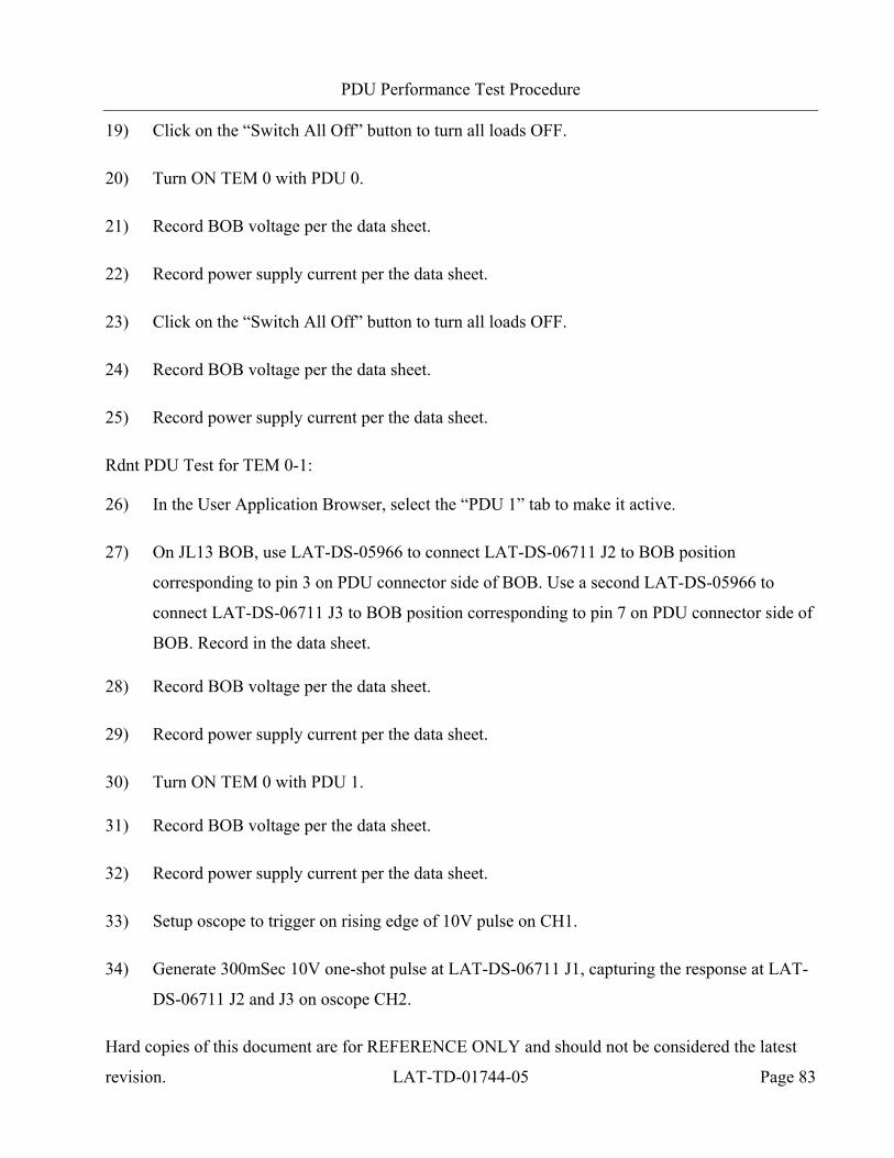
PDU Performance Test Procedure
Hard copies of this document are for REFERENCE ONLY and should not be considered the latest
revision. LAT-TD-01744-05 Page 83
19) Click on the “Switch All Off” button to turn all loads OFF.
20) Turn ON TEM 0 with PDU 0.
21) Record BOB voltage per the data sheet.
22) Record power supply current per the data sheet.
23) Click on the “Switch All Off” button to turn all loads OFF.
24) Record BOB voltage per the data sheet.
25) Record power supply current per the data sheet.
Rdnt PDU Test for TEM 0-1:
26) In the User Application Browser, select the “PDU 1” tab to make it active.
27) On JL13 BOB, use LAT-DS-05966 to connect LAT-DS-06711 J2 to BOB position
corresponding to pin 3 on PDU connector side of BOB. Use a second LAT-DS-05966 to
connect LAT-DS-06711 J3 to BOB position corresponding to pin 7 on PDU connector side of
BOB. Record in the data sheet.
28) Record BOB voltage per the data sheet.
29) Record power supply current per the data sheet.
30) Turn ON TEM 0 with PDU 1.
31) Record BOB voltage per the data sheet.
32) Record power supply current per the data sheet.
33) Setup oscope to trigger on rising edge of 10V pulse on CH1.
34) Generate 300mSec 10V one-shot pulse at LAT-DS-06711 J1, capturing the response at LAT-
DS-06711 J2 and J3 on oscope CH2.
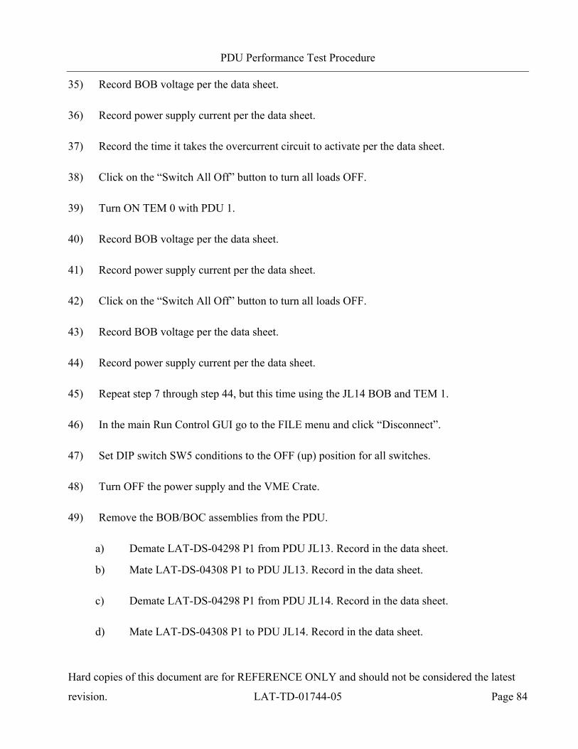
PDU Performance Test Procedure
Hard copies of this document are for REFERENCE ONLY and should not be considered the latest
revision. LAT-TD-01744-05 Page 84
35) Record BOB voltage per the data sheet.
36) Record power supply current per the data sheet.
37) Record the time it takes the overcurrent circuit to activate per the data sheet.
38) Click on the “Switch All Off” button to turn all loads OFF.
39) Turn ON TEM 0 with PDU 1.
40) Record BOB voltage per the data sheet.
41) Record power supply current per the data sheet.
42) Click on the “Switch All Off” button to turn all loads OFF.
43) Record BOB voltage per the data sheet.
44) Record power supply current per the data sheet.
45) Repeat step 7 through step 44, but this time using the JL14 BOB and TEM 1.
46) In the main Run Control GUI go to the FILE menu and click “Disconnect”.
47) Set DIP switch SW5 conditions to the OFF (up) position for all switches.
48) Turn OFF the power supply and the VME Crate.
49) Remove the BOB/BOC assemblies from the PDU.
a) Demate LAT-DS-04298 P1 from PDU JL13. Record in the data sheet.
b) Mate LAT-DS-04308 P1 to PDU JL13. Record in the data sheet.
c) Demate LAT-DS-04298 P1 from PDU JL14. Record in the data sheet.
d) Mate LAT-DS-04308 P1 to PDU JL14. Record in the data sheet.
PDU Performance Test Procedure
Hard copies of this document are for REFERENCE ONLY and should not be considered the latest
revision. LAT-TD-01744-05 Page 85
5.2.6.5 TEM 2-3 Testing
1) Repeat section 5.2.6.4, but this time inserting the BOB/BOC assemblies in line with JL15
and JL16 connections to the PDU and the PDU Load Box, and turning ON/OFF TEM 2 and
TEM 3, respectively.
5.2.6.6 TEM 4-5 Testing
1) Repeat section 5.2.6.4, but this time inserting the BOB/BOC assemblies in line with JL17
and JL18 connections to the PDU and the PDU Load Box, and turning ON/OFF TEM 4 and
TEM 5, respectively.
5.2.6.7 TEM 6-7 Testing
1) Repeat section 5.2.6.4, but this time inserting the BOB/BOC assemblies in line with JL19
and JL20 connections to the PDU and the PDU Load Box, and turning ON/OFF TEM 6 and
TEM 7, respectively.
5.2.6.8 TEM 8-9 Testing
1) Repeat section 5.2.6.4, but this time inserting the BOB/BOC assemblies in line with JL21
and JL22 connections to the PDU and the PDU Load Box, and turning ON/OFF TEM 8 and
TEM 9, respectively.
5.2.6.9 TEM 10-11 Testing
1) Repeat section 5.2.6.4, but this time inserting the BOB/BOC assemblies in line with JL23
and JL24 connections to the PDU and the PDU Load Box, and turning ON/OFF TEM 10 and
TEM 11, respectively.

PDU Performance Test Procedure
Hard copies of this document are for REFERENCE ONLY and should not be considered the latest
revision. LAT-TD-01744-05 Page 86
5.2.6.10 TEM 12-13 Testing
1) Repeat section 5.2.6.4, but this time inserting the BOB/BOC assemblies in line with JL25
and JL26 connections to the PDU and the PDU Load Box, and turning ON/OFF TEM 12 and
TEM 13, respectively.
5.2.6.11 TEM 14-15 Testing
1) Repeat section 5.2.6.4, but this time inserting the BOB/BOC assemblies in line with JL27
and JL28 connections to the PDU and the PDU Load Box, and turning ON/OFF TEM 14 and
TEM 15, respectively.
5.2.6.12 EPU 0-1 Testing
1) Repeat section 5.2.6.4, but this time inserting the BOB/BOC assemblies in line with JL9 and
JL10 connections to the PDU and the PDU Load Box, and turning ON/OFF EPU 0 and EPU
1, respectively.

PDU Performance Test Procedure
Hard copies of this document are for REFERENCE ONLY and should not be considered the latest
revision. LAT-TD-01744-05 Page 87
5.2.6.13 EPU 2 Testing
1) Modify the setup as shown in the Figure below and record the mates/demates to the flight
connector savers in the steps following.
a) Demate LAT-DS-04308 P1 from PDU JL11. Record in the data sheet.
b) Mate BOB/BOC assembly LAT-DS-04298 P1 to PDU JL11. Record in the data sheet.
c) Insert all shorting plugs on the BOB and record.
Overcurrent Test Setup, JL11
2) Turn ON the power supply.
3) Set DIP switch SW5 conditions to turn ON the Prim feed to both PDUs.
4) Set DIP switch SW5 conditions to turn ON the Prim GASU using the Prim PDU.
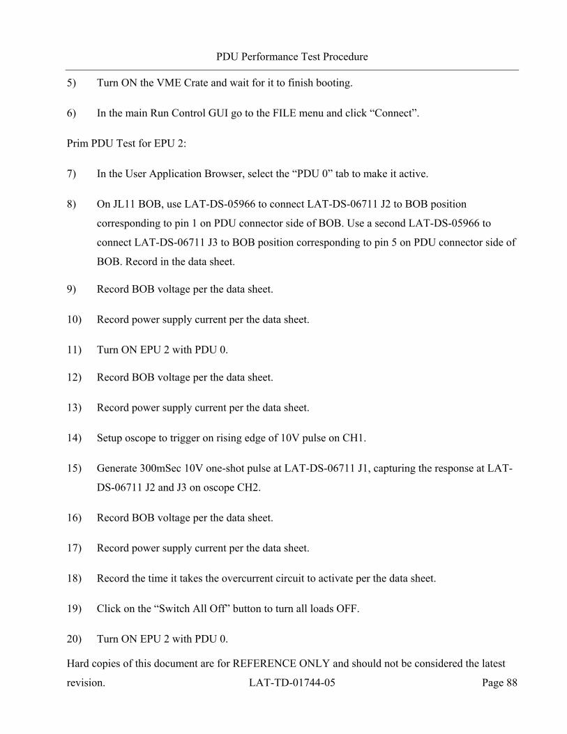
PDU Performance Test Procedure
Hard copies of this document are for REFERENCE ONLY and should not be considered the latest
revision. LAT-TD-01744-05 Page 88
5) Turn ON the VME Crate and wait for it to finish booting.
6) In the main Run Control GUI go to the FILE menu and click “Connect”.
Prim PDU Test for EPU 2:
7) In the User Application Browser, select the “PDU 0” tab to make it active.
8) On JL11 BOB, use LAT-DS-05966 to connect LAT-DS-06711 J2 to BOB position
corresponding to pin 1 on PDU connector side of BOB. Use a second LAT-DS-05966 to
connect LAT-DS-06711 J3 to BOB position corresponding to pin 5 on PDU connector side of
BOB. Record in the data sheet.
9) Record BOB voltage per the data sheet.
10) Record power supply current per the data sheet.
11) Turn ON EPU 2 with PDU 0.
12) Record BOB voltage per the data sheet.
13) Record power supply current per the data sheet.
14) Setup oscope to trigger on rising edge of 10V pulse on CH1.
15) Generate 300mSec 10V one-shot pulse at LAT-DS-06711 J1, capturing the response at LAT-
DS-06711 J2 and J3 on oscope CH2.
16) Record BOB voltage per the data sheet.
17) Record power supply current per the data sheet.
18) Record the time it takes the overcurrent circuit to activate per the data sheet.
19) Click on the “Switch All Off” button to turn all loads OFF.
20) Turn ON EPU 2 with PDU 0.

PDU Performance Test Procedure
Hard copies of this document are for REFERENCE ONLY and should not be considered the latest
revision. LAT-TD-01744-05 Page 89
21) Record BOB voltage per the data sheet.
22) Record power supply current per the data sheet.
23) Click on the “Switch All Off” button to turn all loads OFF.
24) Record BOB voltage per the data sheet.
25) Record power supply current per the data sheet.
Rdnt PDU Test for EPU 2:
26) In the User Application Browser, select the “PDU 1” tab to make it active.
27) On JL11 BOB, use LAT-DS-05966 to connect LAT-DS-06711 J2 to BOB position
corresponding to pin 3 on PDU connector side of BOB. Use a second LAT-DS-05966 to
connect LAT-DS-06711 J3 to BOB position corresponding to pin 7 on PDU connector side of
BOB. Record in the data sheet.
28) Record BOB voltage per the data sheet.
29) Record power supply current per the data sheet.
30) Turn ON EPU 2 with PDU 1.
31) Record BOB voltage per the data sheet.
32) Record power supply current per the data sheet.
33) Setup oscope to trigger on rising edge of 10V pulse on CH1.
34) Generate 300mSec 10V one-shot pulse at LAT-DS-06711 J1, capturing the response at LAT-
DS-06711 J2 and J3 on oscope CH2.
35) Record BOB voltage per the data sheet.
36) Record power supply current per the data sheet.
PDU Performance Test Procedure
Hard copies of this document are for REFERENCE ONLY and should not be considered the latest
revision. LAT-TD-01744-05 Page 90
37) Record the time it takes the overcurrent circuit to activate per the data sheet.
38) Click on the “Switch All Off” button to turn all loads OFF.
39) Turn ON EPU 2 with PDU 1.
40) Record BOB voltage per the data sheet.
41) Record power supply current per the data sheet.
42) Click on the “Switch All Off” button to turn all loads OFF.
43) Record BOB voltage per the data sheet.
44) Record power supply current per the data sheet.
45) Close the main Run Control Application.
46) Set DIP switch SW5 conditions to the OFF (up) position for all switches.
47) Turn OFF the power supply and the VME Crate.
48) Remove the BOB/BOC assembly from the PDU.
a) Demate LAT-DS-04298 P1 from PDU JL11. Record in the data sheet.
b) Mate LAT-DS-04308 P1 to PDU JL11. Record in the data sheet.
PDU Performance Test Procedure
Hard copies of this document are for REFERENCE ONLY and should not be considered the latest
revision. LAT-TD-01744-05 Page 91
5.2.7 Testing the Power Consumption of the PDU (CPT)
This section is executed during CPT only. This test verifies that the PDU supplies power to all loads
and validates the PDU power consumption.
1) Retrieve the resistance of LAT-DS-04309 cable from the LAT-TD-04095 PDU Test Stand
Validation procedure section 5.3.9 that was executed on this Test Stand. Record resistance in
the data sheet.
2) Verify the serial number (GLATxxxx) of the LAT-DS-04309 from the LAT-DS-04095 test
results, is the same as used in this procedure. Record serial number in the data sheet.
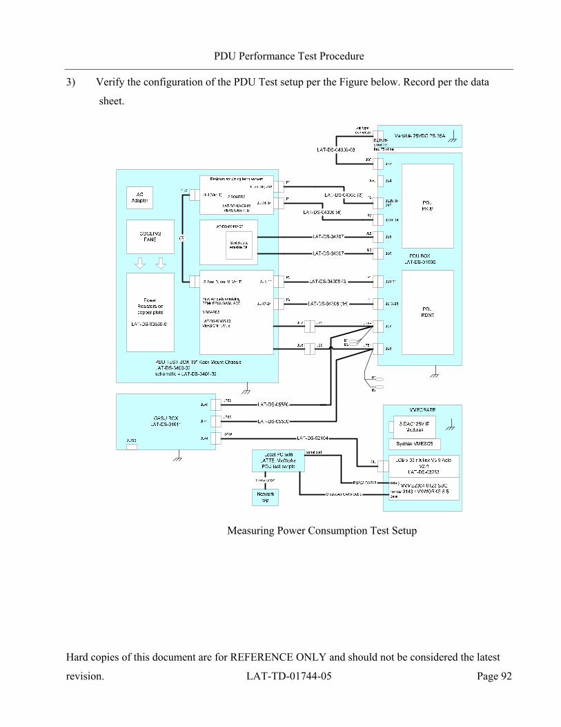
PDU Performance Test Procedure
Hard copies of this document are for REFERENCE ONLY and should not be considered the latest
revision. LAT-TD-01744-05 Page 92
3) Verify the configuration of the PDU Test setup per the Figure below. Record per the data
sheet.
Measuring Power Consumption Test Setup
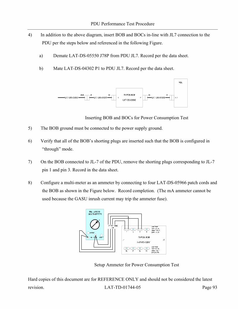
PDU Performance Test Procedure
Hard copies of this document are for REFERENCE ONLY and should not be considered the latest
revision. LAT-TD-01744-05 Page 93
4) In addition to the above diagram, insert BOB and BOCs in-line with JL7 connection to the
PDU per the steps below and referenced in the following Figure.
a) Demate LAT-DS-05550 J78P from PDU JL7. Record per the data sheet.
b) Mate LAT-DS-04302 P1 to PDU JL7. Record per the data sheet.
Inserting BOB and BOCs for Power Consumption Test
5) The BOB ground must be connected to the power supply ground.
6) Verify that all of the BOB’s shorting plugs are inserted such that the BOB is configured in
“through” mode.
7) On the BOB connected to JL-7 of the PDU, remove the shorting plugs corresponding to JL-7
pin 1 and pin 3. Record in the data sheet.
8) Configure a multi-meter as an ammeter by connecting to four LAT-DS-05966 patch cords and
the BOB as shown in the Figure below. Record completion. (The mA ammeter cannot be
used because the GASU inrush current may trip the ammeter fuse).
Setup Ammeter for Power Consumption Test

PDU Performance Test Procedure
Hard copies of this document are for REFERENCE ONLY and should not be considered the latest
revision. LAT-TD-01744-05 Page 94
Perform Test for JL3 connector, Primary and Redundant PDUs:
Note: Make two copies of the data sheets, one for JL3 data, one for JL4 data. JL4 data will be
captured in step 53.
9) Verify that DIP switches SW5 and SW6 on the front panel of the PDU Test Box are all in the
OFF (up) position for all switches
10) Verify that the cooling fans in the PDU Test Box are ON.
11) Turn ON the power supply.
12) Set DIP switch SW5 conditions to turn ON the Prim feed to the Prim PDU ( PDU 0).
13) Set DIP switch SW5 conditions to turn ON the Prim GASU using the Prim PDU.
14) On the ammeter, move the connection on the A input to the mA input and switch the dial to
measure mA. This will provide more resolution for current measurement.
15) On the Windows PC, open a TeraTerm session in serial port mode.
16) Turn ON the VME Crate and wait for it to finish booting before proceeding.
17) Open a command window and run the following batch file: C:\work\runcontrol.bat
18) The Run Control Main GUI appears and prompts for a schema file. Double click on file
"PrimGasuPdu0.xml".
19) In the Run Control Main window, go to the Tools menu and select ‘User Application
Browser’.
20) At the top of the User Application Browser select the PDU tab.
21) Using the scroll bar at the right of the User Application Browser, scroll down until the PDU
power switch buttons are visible. Click “Load” to load the test script.
PDU Performance Test Procedure
Hard copies of this document are for REFERENCE ONLY and should not be considered the latest
revision. LAT-TD-01744-05 Page 95
Primary PDU Measurements with JL3:
22) Verify that the “PDU 0” tab is active.
23) Turn ON all the EPUs (0-2) and all the TEMs (0-15) by clicking their respective buttons to
toggle them ON.
24) Record the current from the power supply front panel, per the data sheet.
25) Using the Agilent multi-meter, measure the voltage across the terminals of the Xantrex power
supply. Record per the data sheet.
26) Using the Agilent multi-meter, measure and record per the data sheet, the voltage across R11
of the top Test Load Interface Board in the PDU Test Box. R11 is located immediately
behind the JL9 connector of the PDU Test Box.
27) Using the Agilent multi-meter, measure and record per the data sheet, the voltage across D3
of the top Test Load Interface Board in the PDU Test Box. D3 is located immediately left of
the JL9 connector of the PDU Test Box.
28) Using the Agilent multi-meter, measure and record per the data sheet, the voltage across
MP14 (red lead) and MP13 (black lead) of the top Test Load Interface Board in the PDU
Test Box. Terminals are located behind the JL9 connector of the PDU Test Box.
29) Using the Agilent multi-meter, measure and record per the data sheet, the voltage across R32
of the top Test Load Interface Board in the PDU Test Box. R32 is located immediately
behind the JL16 connector of the PDU Test Box.
30) Using the Agilent multi-meter, measure and record per the data sheet, the voltage across D6
of the top Test Load Interface Board in the PDU Test Box. D6 is located immediately left of
the JL16 connector of the PDU Test Box.
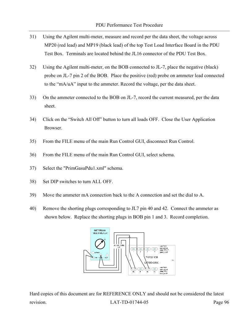
PDU Performance Test Procedure
Hard copies of this document are for REFERENCE ONLY and should not be considered the latest
revision. LAT-TD-01744-05 Page 96
31) Using the Agilent multi-meter, measure and record per the data sheet, the voltage across
MP20 (red lead) and MP19 (black lead) of the top Test Load Interface Board in the PDU
Test Box. Terminals are located behind the JL16 connector of the PDU Test Box.
32) Using the Agilent multi-meter, on the BOB connected to JL-7, place the negative (black)
probe on JL-7 pin 2 of the BOB. Place the positive (red) probe on ammeter lead connected
to the “mA/uA” input to the ammeter. Record the voltage, per the data sheet.
33) On the ammeter connected to the BOB on JL-7, record the current measured, per the data
sheet.
34) Click on the “Switch All Off” button to turn all loads OFF. Close the User Application
Browser.
35) From the FILE menu of the main Run Control GUI, disconnect Run Control.
36) From the FILE menu of the main Run Control GUI, select schema.
37) Select the "PrimGasuPdu1.xml" schema.
38) Set DIP switches to turn ALL OFF.
39) Move the ammeter mA connection back to the A connection and set the dial to A.
40) Remove the shorting plugs corresponding to JL7 pin 40 and 42. Connect the ammeter as
shown below. Replace the shorting plugs in BOB pin 1 and 3. Record completion.
PDU Performance Test Procedure
Hard copies of this document are for REFERENCE ONLY and should not be considered the latest
revision. LAT-TD-01744-05 Page 97
Redundant PDU Measurements with JL3:
41) Set DIP switch SW5 conditions to turn ON the Prim feed to the Rdnt PDU (PDU 1).
42) Set DIP switch SW5 conditions to turn ON the Prim GASU using the Rdnt PDU.
43) On the ammeter, move the connection on the A input to the mA input and switch the dial to
measure mA. This will provide more resolution for current measurement.
44) From the FILE menu of the main Run Control GUI, connect Run Control.
45) Open the User Application Browser and verify the “PDU 1” tab is active.
46) Turn ON all the EPUs (0-2) and all the TEMs (0-15) by clicking their respective buttons to
toggle them ON.
47) Record the current from the power supply front panel, per the data sheet.
48) Using the Agilent multi-meter, measure and record per the data sheet, the voltage across the
terminals of the Xantrex power supply.
49) Using the Agilent multi-meter, measure and record per the data sheet, the voltage across R11
of the top Test Load Interface Board in the PDU Test Box. R11 is located immediately
behind the JL9 connector of the PDU Test Box.
50) Using the Agilent multi-meter, measure and record per the data sheet, the voltage across D3
of the top Test Load Interface Board in the PDU Test Box. D3 is located immediately left of
the JL9 connector of the PDU Test Box.
51) Using the Agilent multi-meter, measure and record per the data sheet, the voltage across
MP14 (red lead) and MP13 (black lead) of the top Test Load Interface Board in the PDU
Test Box. Terminals are located behind the JL9 connector of the PDU Test Box.
PDU Performance Test Procedure
Hard copies of this document are for REFERENCE ONLY and should not be considered the latest
revision. LAT-TD-01744-05 Page 98
52) Using the Agilent multi-meter, measure and record per the data sheet, the voltage across R32
of the top Test Load Interface Board in the PDU Test Box. R32 is located immediately
behind the JL16 connector of the PDU Test Box.
53) Using the Agilent multi-meter, measure and record per the data sheet, the voltage across D6
of the top Test Load Interface Board in the PDU Test Box. D6 is located immediately left of
the JL16 connector of the PDU Test Box.
54) Using the Agilent multi-meter, measure and record per the data sheet, the voltage across
MP20 (red lead) and MP19 (black lead) of the top Test Load Interface Board in the PDU
Test Box. Terminals are located behind the JL16 connector of the PDU Test Box.
55) Using the Agilent multi-meter, on the BOB connected to JL-7, place the negative (black)
probe on JL-7 pin 41 of the BOB. Place the positive (red) probe on ammeter lead connected
to the “mA/uA” input to the ammeter. Record the voltage, per the data sheet.
56) On the ammeter connected to the BOB on JL-7, record the current measured, per the data
sheet.
57) Click on the “Switch All Off” button to turn all loads OFF.
58) Close the Run Control Main application.
59) Set DIP switch SW5 conditions to the OFF (up) position for all switches.
60) Turn OFF the power supply and the VME Crate.
Perform Test for JL4 connector, Primary and Redundant PDUs:
61) Demate LAT-DS-04309 J66 from PDU JL3. Record per the data sheet.
62) Mate LAT-DS-04309 J66 to PDU JL4. Record per the data sheet.
63) Repeat steps 7 through 60 recording voltages and currents per the JL-4 data sheet. This time
the DIP switches must be set to power each PDU using the RDNT FEED (step 12 and 41).
PDU Performance Test Procedure
Hard copies of this document are for REFERENCE ONLY and should not be considered the latest
revision. LAT-TD-01744-05 Page 99
Calculate Power from Test Results:
64) There are four power totals to calculate, Prim PDU with JL3, Rdnt PDU with JL3, Prim PDU
with JL4, and Rdnt PDU with JL4. The following statements apply to cables from the PDU
output connectors to the test loads.
• The constant of 25 Ohms/1000 ft for AWG24 wire is used to calculate the power lost
in cables from the PDU output connectors to the test loads.
• The resistance of one cable is based on the approximation of 2 wires on the hot and 4
wires on the return.
• The cable (LAT-DS-04308) length is “LEN” in inches measured from end-to-end
including connector bodies. Record LEN in the data sheet.
Complete the calculations for Prim PDU power consumption using the data from steps 24
through 33 as follows:
a) PPowIN = (VPS – IPS * R04309) * IPS
b) PPow30 = VR11 * [(VR11 – VD3) / 3300 + VMP1413 / 30] * 3
c) PPow25 = VR32 * [(VR32 – VD6) / 3300 + VMP2019 / 25] * 16
d) PPowGASU = VGASU * IGASU
e) PPowCable30 = [(VR11 – VD3) / 3300 + VMP1413 / 30]2 * (0.025) * (LEN / 12) * (3 / 4) * 3
f) PPowCable25 = [(VR32 – VD6) / 3300 + VMP2019 / 25]2 * (0.025) * (LEN / 12) * (3 / 4) * 16
g) PPowPDU = PPowIN – PPow30 – PPow25 – PPowGASU – PPowCable30 – PPowCable25
h) Record the Prim PDU power in the data sheet.
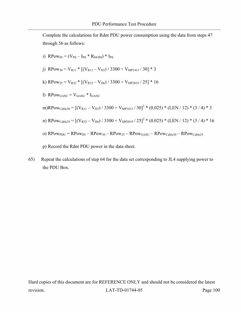
PDU Performance Test Procedure
Hard copies of this document are for REFERENCE ONLY and should not be considered the latest
revision. LAT-TD-01744-05 Page 100
Complete the calculations for Rdnt PDU power consumption using the data from steps 47
through 56 as follows:
i) RPowIN = (VPS – IPS * R04309) * IPS
j) RPow30 = VR11 * [(VR11 – VD3) / 3300 + VMP1413 / 30] * 3
k) RPow25 = VR32 * [(VR32 – VD6) / 3300 + VMP2019 / 25] * 16
l) RPowGASU = VGASU * IGASU
m) RPowCable30 = [(VR11 – VD3) / 3300 + VMP1413 / 30]2 * (0.025) * (LEN / 12) * (3 / 4) * 3
n) RPowCable25 = [(VR32 – VD6) / 3300 + VMP2019 / 25]2 * (0.025) * (LEN / 12) * (3 / 4) * 16
o) RPowPDU = RPowIN – RPow30 – RPow25 – RPowGASU – RPowCable30 – RPowCable25
p) Record the Rdnt PDU power in the data sheet.
65) Repeat the calculations of step 64 for the data set corresponding to JL4 supplying power to
the PDU Box.
PDU Performance Test Procedure
Hard copies of this document are for REFERENCE ONLY and should not be considered the latest
revision. LAT-TD-01744-05 Page 101
5.2.8 Calibrating the Temperature and Voltage Monitors on the PDU (CPT)
This section is executed during CPT only. This test determines the accuracy for all voltage and
temperature monitoring points.
Note: This section outlines the temperature monitor test without the use of LAT-DS-05829 analog
mux board. Thermal Vacuum testing will require the use of this board. The necessary
instructions for using the analog mux board are included separately in the Thermal Vacuum
Test document.
5.2.8.1 Temperature Calibration
1) Verify the configuration of the PDU Test setup per the Figure below and record.

PDU Performance Test Procedure
Hard copies of this document are for REFERENCE ONLY and should not be considered the latest
revision. LAT-TD-01744-05 Page 102
Calibrating Temperature and Voltage Monitors Test Setup
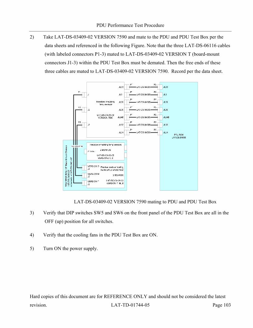
PDU Performance Test Procedure
Hard copies of this document are for REFERENCE ONLY and should not be considered the latest
revision. LAT-TD-01744-05 Page 103
2) Take LAT-DS-03409-02 VERSION 7590 and mate to the PDU and PDU Test Box per the
data sheets and referenced in the following Figure. Note that the three LAT-DS-06116 cables
(with labeled connectors P1-3) mated to LAT-DS-03409-02 VERSION T (board-mount
connectors J1-3) within the PDU Test Box must be demated. Then the free ends of these
three cables are mated to LAT-DS-03409-02 VERSION 7590. Record per the data sheet.
LAT-DS-03409-02 VERSION 7590 mating to PDU and PDU Test Box
3) Verify that DIP switches SW5 and SW6 on the front panel of the PDU Test Box are all in the
OFF (up) position for all switches.
4) Verify that the cooling fans in the PDU Test Box are ON.
5) Turn ON the power supply.

PDU Performance Test Procedure
Hard copies of this document are for REFERENCE ONLY and should not be considered the latest
revision. LAT-TD-01744-05 Page 104
6) Set DIP switch SW6 conditions to turn ON the Prim feed to both PDUs, as shown in the
Figure below.
UP(OFF)
Down(ON)
X
X
X XX X
XX
X X X X
PR
IM P
DU
PR
IM S
C Feed
PR
IM P
DU
RD
NT S
C Feed
PR
IM P
DU
PR
IM G
AS
U
PR
IM P
DU
RD
NT G
AS
U
RD
NT P
DU
PR
IM S
C Feed
RD
NT P
DU
RD
NT S
C Feed
RD
NT P
DU
PR
IM G
AS
U
RD
NT P
DU
RD
NT G
AS
U
Not U
sed
Not U
sed
10 1
JL-3JL-4JL-3JL-4
X XX XX XX X X X
PR
IM P
DU
PR
IM S
C Feed
PR
IM P
DU
RD
NT S
C Feed
PR
IM P
DU
PR
IM G
AS
U
PR
IM P
DU
RD
NT G
AS
U
RD
NT P
DU
PR
IM S
C Feed
RD
NT P
DU
RD
NT S
C Feed
RD
NT P
DU
PR
IM G
AS
U
RD
NT P
DU
RD
NT G
AS
U
Not U
sed
Not U
sed
10 1
JL-3JL-4JL-3JL-4
SW6 (JL-5) SW5 (JL-6)
Primary SIU switching ON JL-3 to both PDUs
7) Set DIP switch SW6 conditions to turn ON the Prim GASU, as shown in the Figure below.
UP(OFF)
Down(ON)
X
X
X XX X
XX
X X X
X
PR
IM P
DU
PR
IM S
C Feed
PR
IM P
DU
RD
NT S
C Feed
PR
IM P
DU
PR
IM G
AS
U
PR
IM P
DU
RD
NT G
AS
U
RD
NT P
DU
PR
IM S
C Feed
RD
NT PD
U R
DN
T SC Feed
RD
NT P
DU
PR
IM G
AS
U
RD
NT P
DU
RD
NT G
AS
U
Not U
sed
Not U
sed
10 1
JL-3JL-4JL-3JL-4
X XX XX XX X X X
PR
IM P
DU
PR
IM S
C Feed
PR
IM P
DU
RD
NT S
C Feed
PR
IM P
DU
PR
IM G
AS
U
PR
IM P
DU
RD
NT G
AS
U
RD
NT P
DU
PR
IM S
C Feed
RD
NT PD
U R
DN
T SC Feed
RD
NT P
DU
PR
IM G
AS
U
RD
NT P
DU
RD
NT G
AS
U
Not U
sed
Not U
sed
10 1
JL-3JL-4JL-3JL-4
SW6 (JL-5) SW5 (JL-6)
Primary SIU switching ON Prim GASU via Prim PDU
8) On the Windows PC, open a TeraTerm session in serial port mode.
9) Turn ON the VME Crate and wait for it to finish booting before proceeding. Status messages
appear in the TeraTerm window.
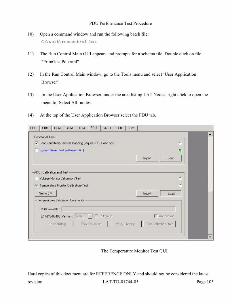
PDU Performance Test Procedure
Hard copies of this document are for REFERENCE ONLY and should not be considered the latest
revision. LAT-TD-01744-05 Page 105
10) Open a command window and run the following batch file: C:\work\runcontrol.bat
11) The Run Control Main GUI appears and prompts for a schema file. Double click on file
"PrimGasuPdu.xml".
12) In the Run Control Main window, go to the Tools menu and select ‘User Application
Browser’.
13) In the User Application Browser, under the area listing LAT Nodes, right click to open the
menu to ‘Select All’ nodes.
14) At the top of the User Application Browser select the PDU tab.
The Temperature Monitor Test GUI
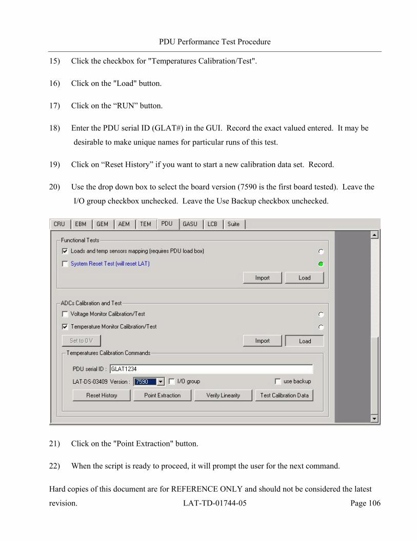
PDU Performance Test Procedure
Hard copies of this document are for REFERENCE ONLY and should not be considered the latest
revision. LAT-TD-01744-05 Page 106
15) Click the checkbox for "Temperatures Calibration/Test".
16) Click on the "Load" button.
17) Click on the “RUN” button.
18) Enter the PDU serial ID (GLAT#) in the GUI. Record the exact valued entered. It may be
desirable to make unique names for particular runs of this test.
19) Click on “Reset History” if you want to start a new calibration data set. Record.
20) Use the drop down box to select the board version (7590 is the first board tested). Leave the
I/O group checkbox unchecked. Leave the Use Backup checkbox unchecked.
21) Click on the "Point Extraction" button.
22) When the script is ready to proceed, it will prompt the user for the next command.
PDU Performance Test Procedure
Hard copies of this document are for REFERENCE ONLY and should not be considered the latest
revision. LAT-TD-01744-05 Page 107
Note: Each successful Point Extraction will store the data collected so far in a temp file. In the
event of a software crash, the script can be restarted and the user can begin collecting data
from where they left off by checking the Use Backup checkbox. The user must recollect data
for the board on which the crash occurred. Uncheck the Use Backup box after collecting the
replacement data point extraction. For further details see file
V:\GLAST\Electronics\ELX\PDU\README.
23) Go to the FILE menu of Run Control Main and select "Disconnect".
24) Set DIP switch SW6 conditions to OFF (up) position for all switches.
25) Turn OFF the power supply.
26) Swap LAT-DS-03409-02 from VERSION 7590 to 19800. (Seven connector demates and
seven connector mates). Record per the data sheet.
27) Turn ON the power supply.
28) Set DIP switch SW6 conditions to turn ON the Prim feed to both PDUs.
29) Set DIP switch SW6 conditions to turn ON the Prim GASU.
30) Go to the FILE menu of Run Control Main and select "Connect".
31) Repeat steps 20 through 25 [this step runs the test and is repeated for each new board].
32) Swap LAT-DS-03409-02 from VERSION 19800 to 30100. Record per the datasheet.
33) Repeat steps 27 through 31.
34) Swap LAT-DS-03409-02 from VERSION 30100 to 60400. Record per the datasheet.
35) Repeat steps 27 through 31.
36) Swap LAT-DS-03409-02 from VERSION 60400 to 205000. Record per the datasheet.
37) Repeat steps 27 through 31.
PDU Performance Test Procedure
Hard copies of this document are for REFERENCE ONLY and should not be considered the latest
revision. LAT-TD-01744-05 Page 108
38) Swap LAT-DS-03409-02 from VERSION 205000 to 361000. Record per the datasheet.
39) Repeat steps 27 through 31.
40) Swap LAT-DS-03409-02 from VERSION 361000 to 806000. Record per the datasheet.
41) Repeat steps 27 through 30.
42) Use the drop down box to select the board version (806000 is the last board tested).
43) Click on the "Point Extraction" button.
44) When the script is ready to proceed, it will prompt the user for the next command.
45) Click on the "Verify Linearity" button.
46) After the test completes, open and print the log file, per the data sheet, and attach it to the data
sheet. Record the test result per the data sheet.
Note: The test data is held in memory while each board is added to the setup and test run. Backup
files are also written upon each successful Point Extraction command. After all
boards are tested the data is then produced and the log files written.
47) Close Run Control.
48) Set DIP switch SW6 conditions to OFF (up) position for all switches.
49) Turn OFF the power supply and the VME Crate.
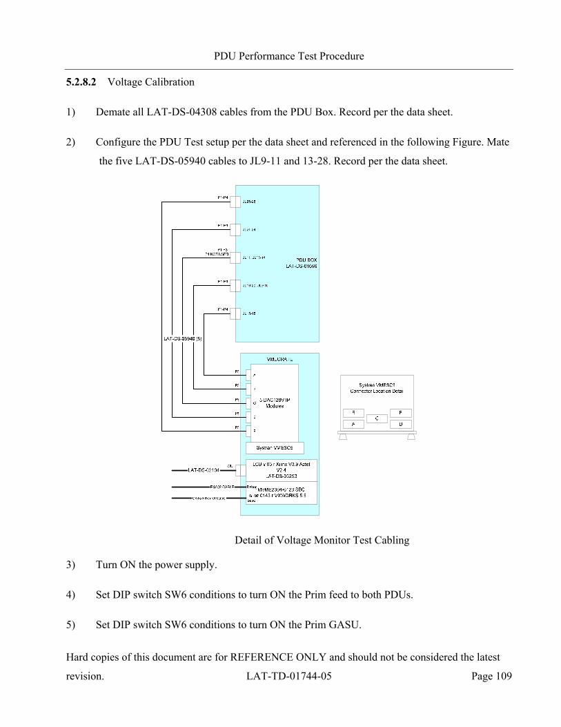
PDU Performance Test Procedure
Hard copies of this document are for REFERENCE ONLY and should not be considered the latest
revision. LAT-TD-01744-05 Page 109
5.2.8.2 Voltage Calibration
1) Demate all LAT-DS-04308 cables from the PDU Box. Record per the data sheet.
2) Configure the PDU Test setup per the data sheet and referenced in the following Figure. Mate
the five LAT-DS-05940 cables to JL9-11 and 13-28. Record per the data sheet.
Detail of Voltage Monitor Test Cabling
3) Turn ON the power supply.
4) Set DIP switch SW6 conditions to turn ON the Prim feed to both PDUs.
5) Set DIP switch SW6 conditions to turn ON the Prim GASU.
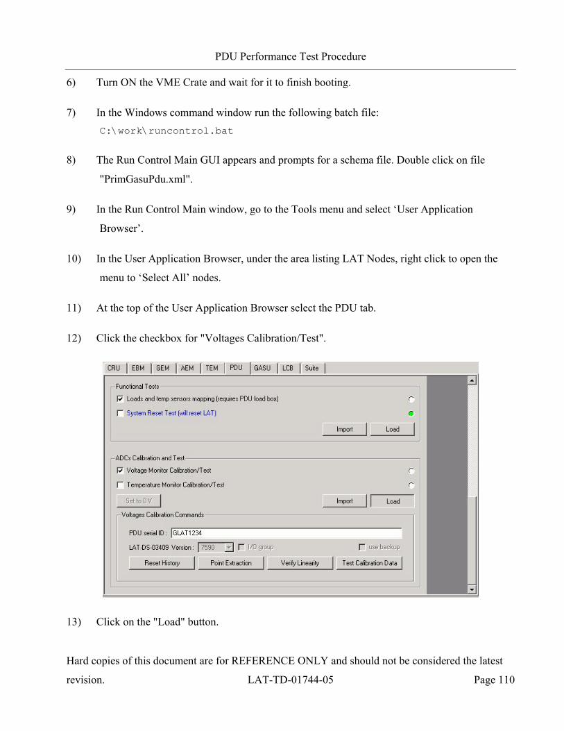
PDU Performance Test Procedure
Hard copies of this document are for REFERENCE ONLY and should not be considered the latest
revision. LAT-TD-01744-05 Page 110
6) Turn ON the VME Crate and wait for it to finish booting.
7) In the Windows command window run the following batch file: C:\work\runcontrol.bat
8) The Run Control Main GUI appears and prompts for a schema file. Double click on file
"PrimGasuPdu.xml".
9) In the Run Control Main window, go to the Tools menu and select ‘User Application
Browser’.
10) In the User Application Browser, under the area listing LAT Nodes, right click to open the
menu to ‘Select All’ nodes.
11) At the top of the User Application Browser select the PDU tab.
12) Click the checkbox for "Voltages Calibration/Test".
13) Click on the "Load" button.
PDU Performance Test Procedure
Hard copies of this document are for REFERENCE ONLY and should not be considered the latest
revision. LAT-TD-01744-05 Page 111
14) Click on the “RUN” button.
15) Enter the PDU serial ID (GLAT#) in the GUI. Record the exact valued entered. It may be
desirable to make unique names for particular runs of this test.
16) Click on “Reset History” to start a new calibration data set. Record in the data sheet.
17) Click on the "Point Extraction" button.
18) When the script is ready to proceed, it will prompt the user for the next command.
19) Click on the "Verify Linearity" button.
20) After the test completes, open and print the log file, per the data sheet, and attach it to the data
sheet. Record the test result per the data sheet.
21) Click on the “RUN” button.
22) Enter the PDU serial ID (GLAT#) in the GUI. Make certain that the same exact value from
the previous RUN is entered.
23) Click on the "Point Extraction" button.
24) When the script is ready to proceed, it will prompt the user for the next command.
25) Click on the "Verify Linearity" button.
26) After the test completes, open and print the log file, per the data sheet, and attach it to the data
sheet. Record the test result per the data sheet.
27) Click on the “RUN” button.
28) Enter the PDU serial ID (GLAT#) in the GUI. Make certain that the same exact value from
the previous RUN is entered.

PDU Performance Test Procedure
Hard copies of this document are for REFERENCE ONLY and should not be considered the latest
revision. LAT-TD-01744-05 Page 112
29) Click on the "Test Calibration Data" button. This checks the stability of the calibration data
by comparing the two sets of point extractions just completed.
30) After the test completes, open and print the log file, per the data sheet, and attach it to the data
sheet. Record the test result per the data sheet.
31) Close Run Control.
32) Set DIP switch SW6 conditions to OFF (up) position for all switches.
33) Turn OFF the power supply and the VME Crate.
34) Demate the LAT-DS-5940 cables and record per the data sheet.
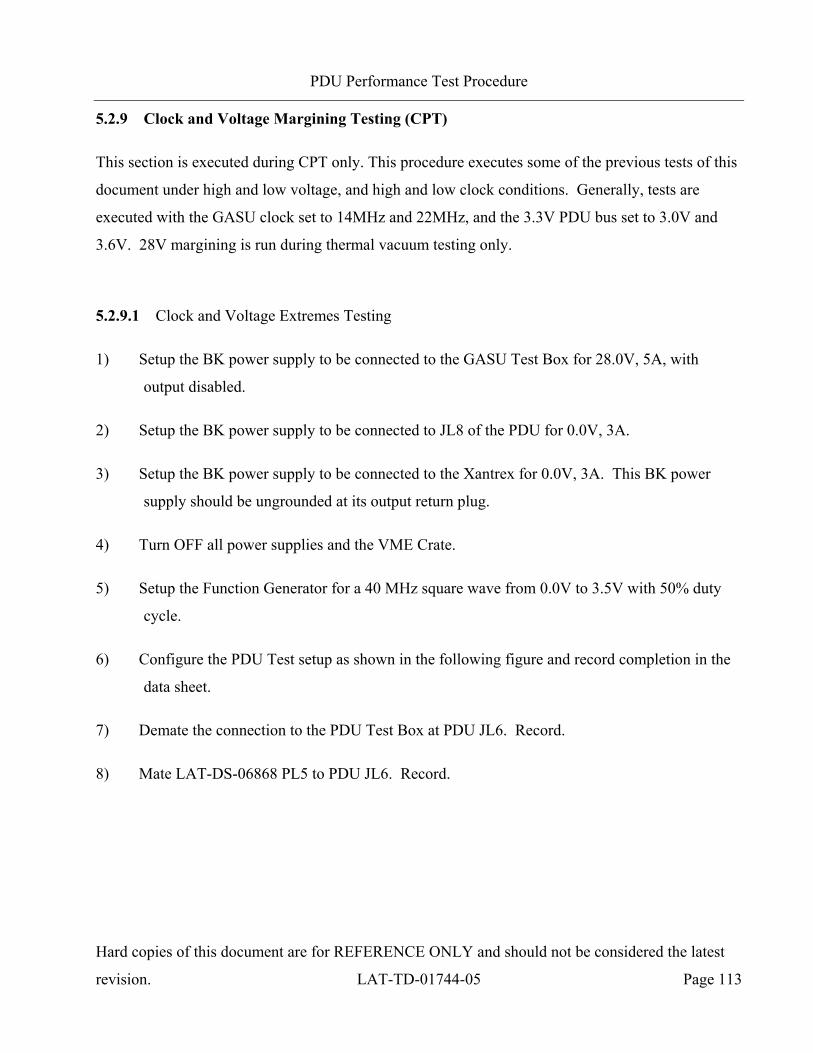
PDU Performance Test Procedure
Hard copies of this document are for REFERENCE ONLY and should not be considered the latest
revision. LAT-TD-01744-05 Page 113
5.2.9 Clock and Voltage Margining Testing (CPT)
This section is executed during CPT only. This procedure executes some of the previous tests of this
document under high and low voltage, and high and low clock conditions. Generally, tests are
executed with the GASU clock set to 14MHz and 22MHz, and the 3.3V PDU bus set to 3.0V and
3.6V. 28V margining is run during thermal vacuum testing only.
5.2.9.1 Clock and Voltage Extremes Testing
1) Setup the BK power supply to be connected to the GASU Test Box for 28.0V, 5A, with
output disabled.
2) Setup the BK power supply to be connected to JL8 of the PDU for 0.0V, 3A.
3) Setup the BK power supply to be connected to the Xantrex for 0.0V, 3A. This BK power
supply should be ungrounded at its output return plug.
4) Turn OFF all power supplies and the VME Crate.
5) Setup the Function Generator for a 40 MHz square wave from 0.0V to 3.5V with 50% duty
cycle.
6) Configure the PDU Test setup as shown in the following figure and record completion in the
data sheet.
7) Demate the connection to the PDU Test Box at PDU JL6. Record.
8) Mate LAT-DS-06868 PL5 to PDU JL6. Record.
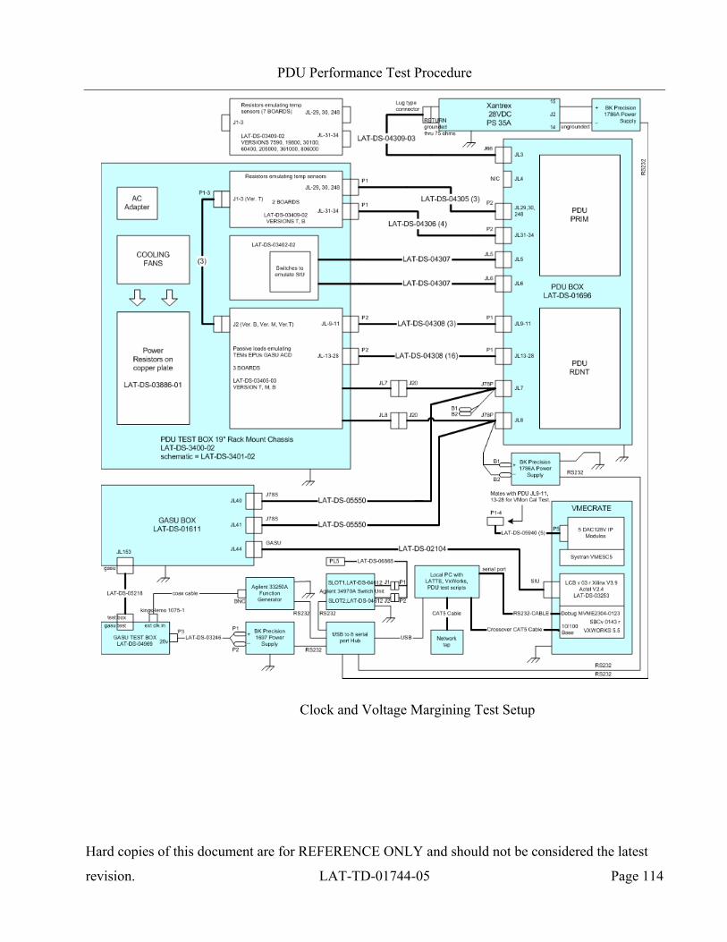
PDU Performance Test Procedure
Hard copies of this document are for REFERENCE ONLY and should not be considered the latest
revision. LAT-TD-01744-05 Page 114
Clock and Voltage Margining Test Setup
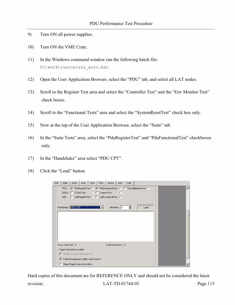
PDU Performance Test Procedure
Hard copies of this document are for REFERENCE ONLY and should not be considered the latest
revision. LAT-TD-01744-05 Page 115
9) Turn ON all power supplies.
10) Turn ON the VME Crate.
11) In the Windows command window run the following batch file: C:\work\runcontrol_auto.bat
12) Open the User Application Browser, select the “PDU” tab, and select all LAT nodes.
13) Scroll to the Register Test area and select the “Controller Test” and the “Env Monitor Test”
check boxes.
14) Scroll to the “Functional Tests” area and select the “SystemResetTest” check box only.
15) Now at the top of the User Application Browser, select the “Suite” tab.
16) In the “Suite Tests” area, select the “PduRegisterTest” and “PduFunctionalTest” checkboxes
only.
17) In the “Handshake” area select “PDU CPT”.
18) Click the “Load” button.

PDU Performance Test Procedure
Hard copies of this document are for REFERENCE ONLY and should not be considered the latest
revision. LAT-TD-01744-05 Page 116
19) Click “RUN” (Play) in the User Application Browser to run the test. Follow the prompts of
the test script to mate and demate the GASU Test Cable and to setup the GASU Test Box.
This test runs tests under the conditions listed in the following table.
PDU Main Power
3.3V margining
power supply
PDU 3.3V Bus
GASU Ext Clk
Temperature C
28V 3.8V 3.0V 40MHz 25
0.4V 3.6V 40MHz
2.0V 3.3V 40MHz
28MHz
44MHz
20) When the test is complete, record results in the data sheet and print the log files.
21) Set the BK connected to the Xantrex to 3.0V which should bring the Xantrex out of shutdown
to 28V.
22) Set the BK connected to PDU JL8 cabling to 3.8V.
23) Repeat section 5.2.4 steps 1 through 19.
24) Set the BK connected to PDU JL8 cabling to 0.4V.
25) Repeat section 5.2.4 steps 1 through 19.
26) Close Run Control and shutdown the Xantrex. Turn off the BK connected to PDU JL8
cabling.
27) Repeat section 5.2.8.2 following the special instructions noted in this step. You must set the
BK connected to the Xantrex to 3.0V which should bring the Xantrex out of shutdown to
28V, and, you must set the BK connected to PDU JL8 cabling to 3.8V, during the power
supply turn-on steps of section 5.2.8.2. Do not “Reset History”. Use the same PDU serial ID
PDU Performance Test Procedure
Hard copies of this document are for REFERENCE ONLY and should not be considered the latest
revision. LAT-TD-01744-05 Page 117
field as was used during the first execution of 5.2.8.2. Do only one “Point Extraction” and
“Verify Linearity”. Then do one “Test Calibration data. This will check the stability of the
voltage monitor calibration constants when the PDU 3.3V bus is margined.
28) Repeat step 27 with the BK connected to PDU JL8 cabling set to 0.4V.
29) Close Run Control.
30) Turn OFF the VME Crate.
31) Turn OFF the GASU and PDUs.
32) Turn OFF all power supplies.
PDU Performance Test Procedure
Hard copies of this document are for REFERENCE ONLY and should not be considered the latest
revision. LAT-TD-01744-05 Page 118
Appendix A (Cover and Data Sheets)
PDU Performance Test Procedure
Hard copies of this document are for REFERENCE ONLY and should not be considered the latest
revision. LAT-TD-01744-05 Page 119
COVER SHEET
Program: GLAST
Procedure Number: LAT-TD-01744
Procedure Title: PDU Performance Test Procedure
Paragraph Number: 5.
Paragraph Title: Procedure
Controlling Document Number:
Controlling Document Step Number:
Unit S/N:
Descriptive Comment:
TEST READINESS REVIEW COMPLETED AND APPROVED BY THE FOLLOWING:
Test Director: Date:
Quality Assurance: Date:
Test Conductor: Date:
POST TEST REVIEW COMPLETED AND APPROVED BY THE FOLLOWING:
Test Director: Date:
Quality Assurance: Date:
Test Conductor: Date:
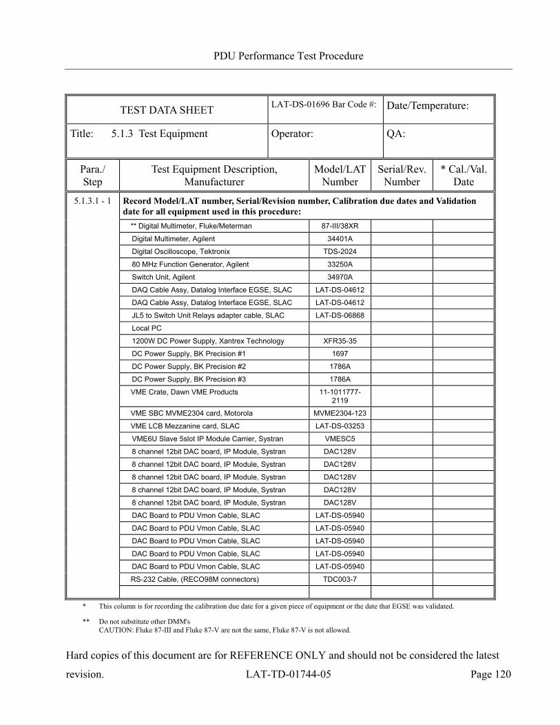
PDU Performance Test Procedure
Hard copies of this document are for REFERENCE ONLY and should not be considered the latest
revision. LAT-TD-01744-05 Page 120
TEST DATA SHEET LAT-DS-01696 Bar Code #:
Date/Temperature:
Title: 5.1.3 Test Equipment Operator:
QA:
Para./ Step
Test Equipment Description, Manufacturer
Model/LATNumber
Serial/Rev. Number
* Cal./Val. Date
5.1.3.1 - 1 Record Model/LAT number, Serial/Revision number, Calibration due dates and Validation date for all equipment used in this procedure:
** Digital Multimeter, Fluke/Meterman 87-III/38XR
Digital Multimeter, Agilent 34401A
Digital Oscilloscope, Tektronix TDS-2024
80 MHz Function Generator, Agilent 33250A
Switch Unit, Agilent 34970A
DAQ Cable Assy, Datalog Interface EGSE, SLAC LAT-DS-04612
DAQ Cable Assy, Datalog Interface EGSE, SLAC LAT-DS-04612
JL5 to Switch Unit Relays adapter cable, SLAC LAT-DS-06868
Local PC
1200W DC Power Supply, Xantrex Technology XFR35-35
DC Power Supply, BK Precision #1 1697
DC Power Supply, BK Precision #2 1786A
DC Power Supply, BK Precision #3 1786A
VME Crate, Dawn VME Products 11-1011777-2119
VME SBC MVME2304 card, Motorola MVME2304-123
VME LCB Mezzanine card, SLAC LAT-DS-03253
VME6U Slave 5slot IP Module Carrier, Systran VMESC5
8 channel 12bit DAC board, IP Module, Systran DAC128V
8 channel 12bit DAC board, IP Module, Systran DAC128V
8 channel 12bit DAC board, IP Module, Systran DAC128V
8 channel 12bit DAC board, IP Module, Systran DAC128V
8 channel 12bit DAC board, IP Module, Systran DAC128V
DAC Board to PDU Vmon Cable, SLAC LAT-DS-05940
DAC Board to PDU Vmon Cable, SLAC LAT-DS-05940
DAC Board to PDU Vmon Cable, SLAC LAT-DS-05940
DAC Board to PDU Vmon Cable, SLAC LAT-DS-05940
DAC Board to PDU Vmon Cable, SLAC LAT-DS-05940
RS-232 Cable, (RECO98M connectors) TDC003-7
* This column is for recording the calibration due date for a given piece of equipment or the date that EGSE was validated.
** Do not substitute other DMM's CAUTION: Fluke 87-III and Fluke 87-V are not the same, Fluke 87-V is not allowed.
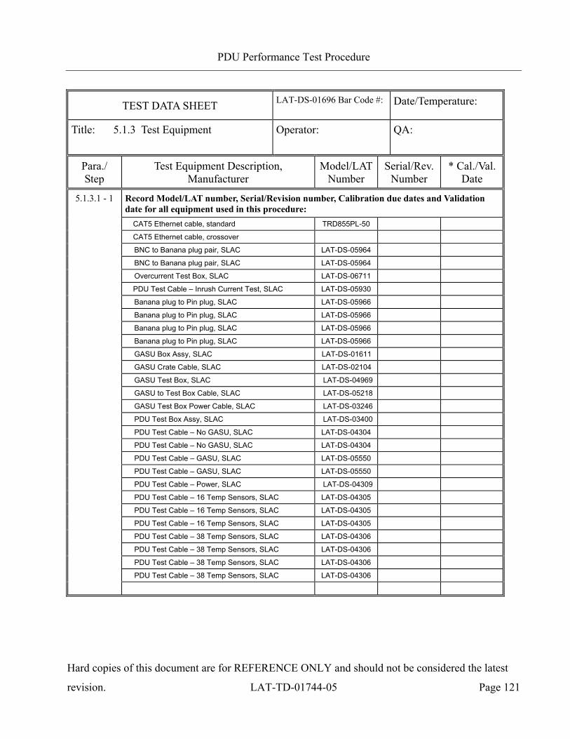
PDU Performance Test Procedure
Hard copies of this document are for REFERENCE ONLY and should not be considered the latest
revision. LAT-TD-01744-05 Page 121
TEST DATA SHEET LAT-DS-01696 Bar Code #:
Date/Temperature:
Title: 5.1.3 Test Equipment Operator:
QA:
Para./ Step
Test Equipment Description, Manufacturer
Model/LATNumber
Serial/Rev. Number
* Cal./Val. Date
5.1.3.1 - 1 Record Model/LAT number, Serial/Revision number, Calibration due dates and Validation date for all equipment used in this procedure:
CAT5 Ethernet cable, standard TRD855PL-50
CAT5 Ethernet cable, crossover
BNC to Banana plug pair, SLAC LAT-DS-05964
BNC to Banana plug pair, SLAC LAT-DS-05964
Overcurrent Test Box, SLAC LAT-DS-06711
PDU Test Cable – Inrush Current Test, SLAC LAT-DS-05930
Banana plug to Pin plug, SLAC LAT-DS-05966
Banana plug to Pin plug, SLAC LAT-DS-05966
Banana plug to Pin plug, SLAC LAT-DS-05966
Banana plug to Pin plug, SLAC LAT-DS-05966
GASU Box Assy, SLAC LAT-DS-01611
GASU Crate Cable, SLAC LAT-DS-02104
GASU Test Box, SLAC LAT-DS-04969
GASU to Test Box Cable, SLAC LAT-DS-05218
GASU Test Box Power Cable, SLAC LAT-DS-03246
PDU Test Box Assy, SLAC LAT-DS-03400
PDU Test Cable – No GASU, SLAC LAT-DS-04304
PDU Test Cable – No GASU, SLAC LAT-DS-04304
PDU Test Cable – GASU, SLAC LAT-DS-05550
PDU Test Cable – GASU, SLAC LAT-DS-05550
PDU Test Cable – Power, SLAC LAT-DS-04309
PDU Test Cable – 16 Temp Sensors, SLAC LAT-DS-04305
PDU Test Cable – 16 Temp Sensors, SLAC LAT-DS-04305
PDU Test Cable – 16 Temp Sensors, SLAC LAT-DS-04305
PDU Test Cable – 38 Temp Sensors, SLAC LAT-DS-04306
PDU Test Cable – 38 Temp Sensors, SLAC LAT-DS-04306
PDU Test Cable – 38 Temp Sensors, SLAC LAT-DS-04306
PDU Test Cable – 38 Temp Sensors, SLAC LAT-DS-04306
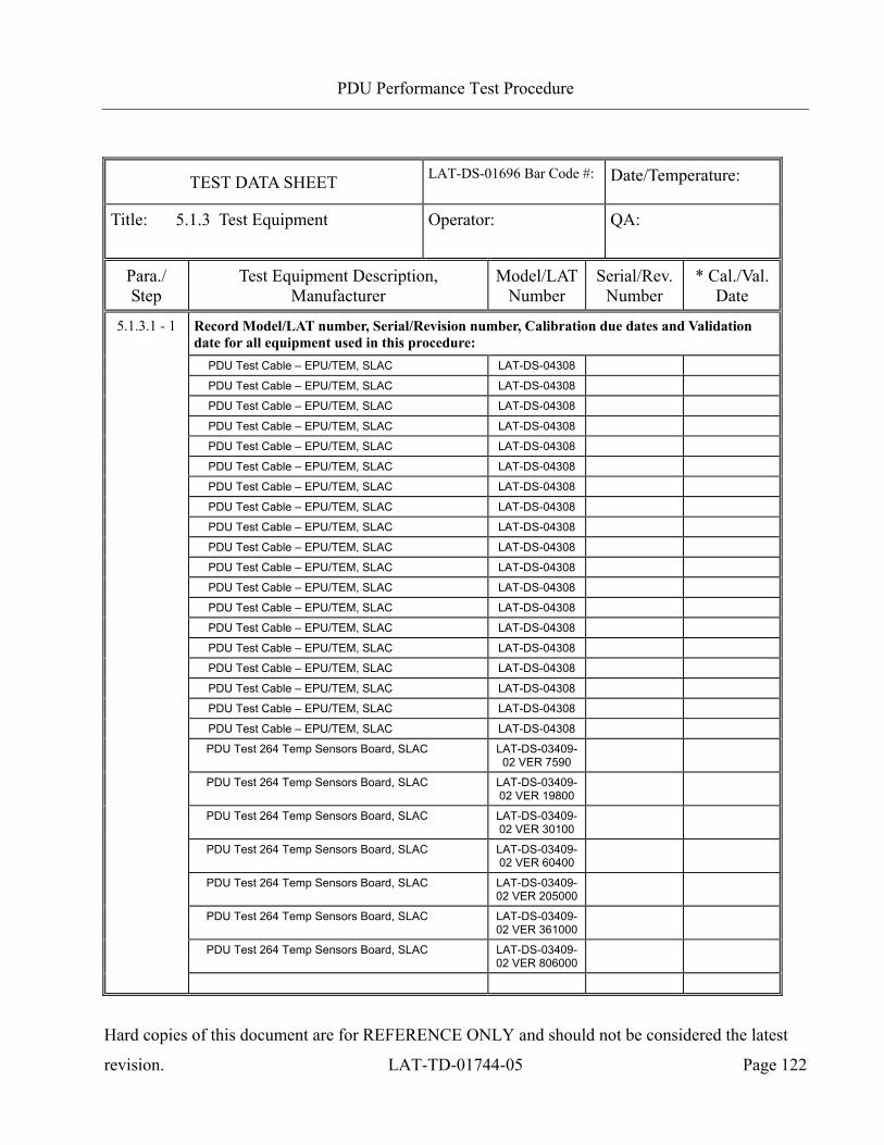
PDU Performance Test Procedure
Hard copies of this document are for REFERENCE ONLY and should not be considered the latest
revision. LAT-TD-01744-05 Page 122
TEST DATA SHEET LAT-DS-01696 Bar Code #:
Date/Temperature:
Title: 5.1.3 Test Equipment Operator:
QA:
Para./ Step
Test Equipment Description, Manufacturer
Model/LATNumber
Serial/Rev. Number
* Cal./Val. Date
5.1.3.1 - 1 Record Model/LAT number, Serial/Revision number, Calibration due dates and Validation date for all equipment used in this procedure:
PDU Test Cable – EPU/TEM, SLAC LAT-DS-04308
PDU Test Cable – EPU/TEM, SLAC LAT-DS-04308
PDU Test Cable – EPU/TEM, SLAC LAT-DS-04308
PDU Test Cable – EPU/TEM, SLAC LAT-DS-04308
PDU Test Cable – EPU/TEM, SLAC LAT-DS-04308
PDU Test Cable – EPU/TEM, SLAC LAT-DS-04308
PDU Test Cable – EPU/TEM, SLAC LAT-DS-04308
PDU Test Cable – EPU/TEM, SLAC LAT-DS-04308
PDU Test Cable – EPU/TEM, SLAC LAT-DS-04308
PDU Test Cable – EPU/TEM, SLAC LAT-DS-04308
PDU Test Cable – EPU/TEM, SLAC LAT-DS-04308
PDU Test Cable – EPU/TEM, SLAC LAT-DS-04308
PDU Test Cable – EPU/TEM, SLAC LAT-DS-04308
PDU Test Cable – EPU/TEM, SLAC LAT-DS-04308
PDU Test Cable – EPU/TEM, SLAC LAT-DS-04308
PDU Test Cable – EPU/TEM, SLAC LAT-DS-04308
PDU Test Cable – EPU/TEM, SLAC LAT-DS-04308
PDU Test Cable – EPU/TEM, SLAC LAT-DS-04308
PDU Test Cable – EPU/TEM, SLAC LAT-DS-04308
PDU Test 264 Temp Sensors Board, SLAC LAT-DS-03409-02 VER 7590
PDU Test 264 Temp Sensors Board, SLAC LAT-DS-03409-02 VER 19800
PDU Test 264 Temp Sensors Board, SLAC LAT-DS-03409-02 VER 30100
PDU Test 264 Temp Sensors Board, SLAC LAT-DS-03409-02 VER 60400
PDU Test 264 Temp Sensors Board, SLAC LAT-DS-03409-02 VER 205000
PDU Test 264 Temp Sensors Board, SLAC LAT-DS-03409-02 VER 361000
PDU Test 264 Temp Sensors Board, SLAC LAT-DS-03409-02 VER 806000
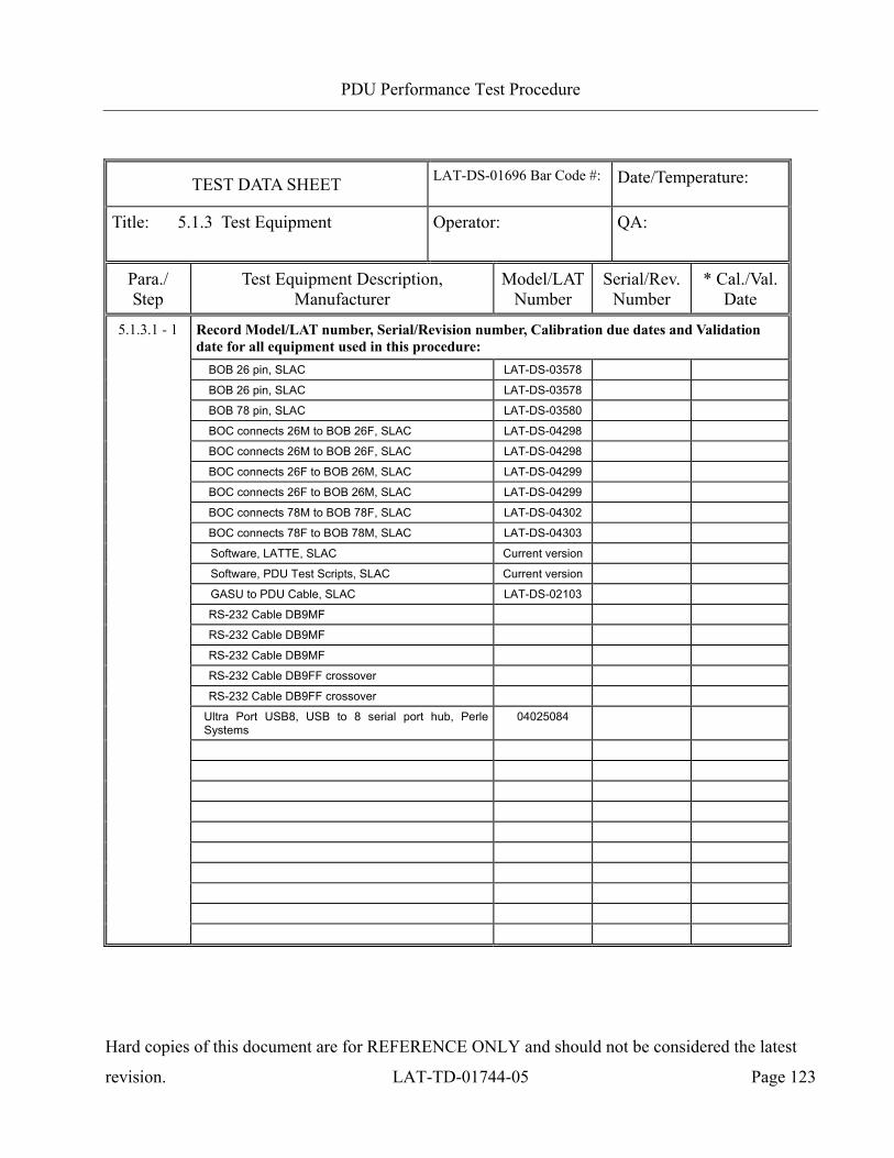
PDU Performance Test Procedure
Hard copies of this document are for REFERENCE ONLY and should not be considered the latest
revision. LAT-TD-01744-05 Page 123
TEST DATA SHEET LAT-DS-01696 Bar Code #:
Date/Temperature:
Title: 5.1.3 Test Equipment Operator:
QA:
Para./ Step
Test Equipment Description, Manufacturer
Model/LATNumber
Serial/Rev. Number
* Cal./Val. Date
5.1.3.1 - 1 Record Model/LAT number, Serial/Revision number, Calibration due dates and Validation date for all equipment used in this procedure:
BOB 26 pin, SLAC LAT-DS-03578
BOB 26 pin, SLAC LAT-DS-03578
BOB 78 pin, SLAC LAT-DS-03580
BOC connects 26M to BOB 26F, SLAC LAT-DS-04298
BOC connects 26M to BOB 26F, SLAC LAT-DS-04298
BOC connects 26F to BOB 26M, SLAC LAT-DS-04299
BOC connects 26F to BOB 26M, SLAC LAT-DS-04299
BOC connects 78M to BOB 78F, SLAC LAT-DS-04302
BOC connects 78F to BOB 78M, SLAC LAT-DS-04303
Software, LATTE, SLAC Current version
Software, PDU Test Scripts, SLAC Current version
GASU to PDU Cable, SLAC LAT-DS-02103
RS-232 Cable DB9MF
RS-232 Cable DB9MF
RS-232 Cable DB9MF
RS-232 Cable DB9FF crossover
RS-232 Cable DB9FF crossover
Ultra Port USB8, USB to 8 serial port hub, Perle Systems
04025084
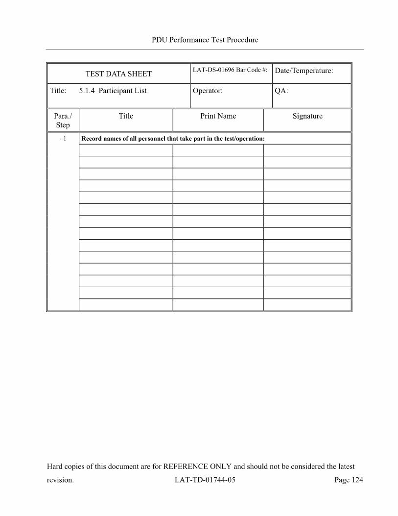
PDU Performance Test Procedure
Hard copies of this document are for REFERENCE ONLY and should not be considered the latest
revision. LAT-TD-01744-05 Page 124
TEST DATA SHEET LAT-DS-01696 Bar Code #:
Date/Temperature:
Title: 5.1.4 Participant List Operator:
QA:
Para./ Step
Title Print Name Signature
Record names of all personnel that take part in the test/operation:
- 1
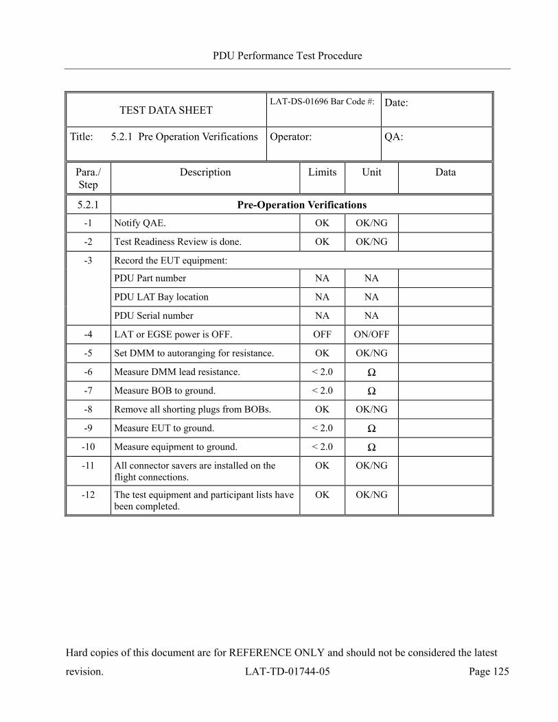
PDU Performance Test Procedure
Hard copies of this document are for REFERENCE ONLY and should not be considered the latest
revision. LAT-TD-01744-05 Page 125
TEST DATA SHEET LAT-DS-01696 Bar Code #:
Date:
Title: 5.2.1 Pre Operation Verifications Operator:
QA:
Para./ Step
Description Limits Unit Data
5.2.1 Pre-Operation Verifications -1 Notify QAE. OK OK/NG -2 Test Readiness Review is done. OK OK/NG
Record the EUT equipment:
PDU Part number NA NA PDU LAT Bay location NA NA
-3
PDU Serial number NA NA -4 LAT or EGSE power is OFF. OFF ON/OFF -5 Set DMM to autoranging for resistance. OK OK/NG
-6 Measure DMM lead resistance. < 2.0 Ω -7 Measure BOB to ground. < 2.0 Ω -8 Remove all shorting plugs from BOBs. OK OK/NG -9 Measure EUT to ground. < 2.0 Ω
-10 Measure equipment to ground. < 2.0 Ω
-11 All connector savers are installed on the flight connections.
OK OK/NG
-12 The test equipment and participant lists have been completed.
OK OK/NG
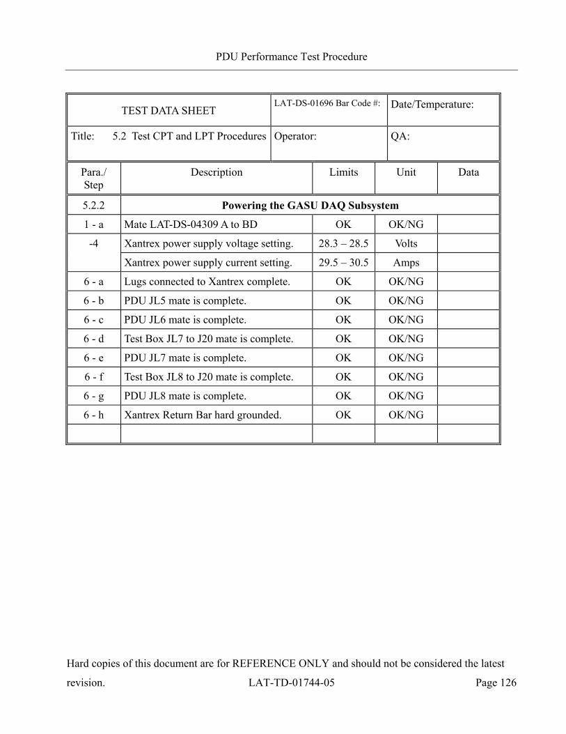
PDU Performance Test Procedure
Hard copies of this document are for REFERENCE ONLY and should not be considered the latest
revision. LAT-TD-01744-05 Page 126
TEST DATA SHEET LAT-DS-01696 Bar Code #:
Date/Temperature:
Title: 5.2 Test CPT and LPT Procedures Operator:
QA:
Para./ Step
Description Limits Unit Data
5.2.2 Powering the GASU DAQ Subsystem
1 - a Mate LAT-DS-04309 A to BD OK OK/NG
-4 Xantrex power supply voltage setting. 28.3 – 28.5 Volts
Xantrex power supply current setting. 29.5 – 30.5 Amps
6 - a Lugs connected to Xantrex complete. OK OK/NG
6 - b PDU JL5 mate is complete. OK OK/NG
6 - c PDU JL6 mate is complete. OK OK/NG
6 - d Test Box JL7 to J20 mate is complete. OK OK/NG
6 - e PDU JL7 mate is complete. OK OK/NG
6 - f Test Box JL8 to J20 mate is complete. OK OK/NG
6 - g PDU JL8 mate is complete. OK OK/NG
6 - h Xantrex Return Bar hard grounded. OK OK/NG

PDU Performance Test Procedure
Hard copies of this document are for REFERENCE ONLY and should not be considered the latest
revision. LAT-TD-01744-05 Page 127
TEST DATA SHEET LAT-DS-01696 Bar Code #:
Date/Temperature:
Title: 5.2 Test CPT and LPT Procedures Operator:
QA:
Para./ Step
Description Limits Unit Data
5.2.2 Powering the GASU DAQ Subsystem
-12 Xantrex power supply current. 0.90 - 1.00 Amps
Primary GASU LED illuminates. ON ON/OFF
-14 Xantrex power supply current. 0.90 - 1.00 Amps
Redundant GASU LED illuminates. ON ON/OFF
-16 Xantrex power supply current. 0.90 - 1.00 Amps
Primary GASU LED illuminates. ON ON/OFF
-18 Xantrex power supply current. 0.90 - 1.00 Amps
Redundant GASU LED illuminates. ON ON/OFF
-21 Xantrex power supply current. 0.90 - 1.00 Amps
Primary GASU LED illuminates. ON ON/OFF
-23 Xantrex power supply current. 0.90 - 1.00 Amps
Redundant GASU LED illuminates. ON ON/OFF
-25 Xantrex power supply current. 0.90 - 1.00 Amps
Primary GASU LED illuminates. ON ON/OFF
-27 Xantrex power supply current. 0.90 - 1.00 Amps
Redundant GASU LED illuminates. ON ON/OFF
30 – a Test Box JL7 demate is complete. OK OK/NG
30 – b PDU JL7 demate is complete. OK OK/NG
30 – c Test Box JL8 demate is complete. OK OK/NG
30 – d PDU JL8 demate is complete. OK OK/NG
30 – e Xantrex hard ground on return bar removed.
OK OK/NG

PDU Performance Test Procedure
Hard copies of this document are for REFERENCE ONLY and should not be considered the latest
revision. LAT-TD-01744-05 Page 128
TEST DATA SHEET LAT-DS-01696 Bar Code #:
Date/Temperature:
Title: 5.2 Test CPT and LPT Procedures Operator:
QA:
Para./ Step
Description Limits Unit Data
5.2.3 Register Test
1 – a Test Box JL7 mate is complete. OK OK/NG
1 – b PDU JL7 mate is complete. OK OK/NG
1 – c Test Box JL8 mate is complete. OK OK/NG
1 – d PDU JL8 mate is complete. OK OK/NG
1 – e JL40 mate is complete. OK OK/NG
1 – f JL41 mate is complete. OK OK/NG
1 – g PDU JL29 mate is complete. OK OK/NG
1 – h PDU JL30 mate is complete. OK OK/NG
1 – i PDU JL248 mate is complete. OK OK/NG
1 – j PDU JL31 mate is complete. OK OK/NG
1 – k PDU JL32 mate is complete. OK OK/NG
1 – l PDU JL33 mate is complete. OK OK/NG
1 – m PDU JL34 mate is complete. OK OK/NG
1 – n PDU JL9 mate is complete. OK OK/NG
1 – o PDU JL10 mate is complete. OK OK/NG
1 – p PDU JL11 mate is complete. OK OK/NG
1 – q PDU JL13 mate is complete. OK OK/NG
1 – r PDU JL14 mate is complete. OK OK/NG
1 – s PDU JL15 mate is complete. OK OK/NG
1 – t PDU JL16 mate is complete. OK OK/NG
1 – u PDU JL17 mate is complete. OK OK/NG
1 – v PDU JL18 mate is complete. OK OK/NG
1 – w PDU JL19 mate is complete. OK OK/NG

PDU Performance Test Procedure
Hard copies of this document are for REFERENCE ONLY and should not be considered the latest
revision. LAT-TD-01744-05 Page 129
TEST DATA SHEET LAT-DS-01696 Bar Code #:
Date/Temperature:
Title: 5.2 Test CPT and LPT Procedures Operator:
QA:
Para./ Step
Description Limits Unit Data
5.2.3 Register Test
1 – x PDU JL20 mate is complete. OK OK/NG
1 – y PDU JL21 mate is complete. OK OK/NG
1 – z PDU JL22 mate is complete. OK OK/NG
1 – aa PDU JL23 mate is complete. OK OK/NG
1 – bb PDU JL24 mate is complete. OK OK/NG
1 – cc PDU JL25 mate is complete. OK OK/NG
1 – dd PDU JL26 mate is complete. OK OK/NG
1 – ee PDU JL27 mate is complete. OK OK/NG
1 – ff PDU JL28 mate is complete. OK OK/NG
-6 Record power supply current 0.2 - 0.4 Amps
-23 Verify that the Prim GASU register test passed
OK OK/NG
-28 Verify that the Prim GASU functional test passed
OK OK/NG
-34 Record power supply current 0.2 - 0.4 Amps
-35 Verify that the Rdnt GASU register test passed
OK OK/NG
-35 Verify that the Rdnt GASU functional test passed
OK OK/NG

PDU Performance Test Procedure
Hard copies of this document are for REFERENCE ONLY and should not be considered the latest
revision. LAT-TD-01744-05 Page 130
TEST DATA SHEET LAT-DS-01696 Bar Code #:
Date/Temperature:
Title: 5.2 Test CPT and LPT Procedures Operator:
QA:
Para./ Step
Description Limits Unit Data
5.2.4 Load Board Mapping, Load Shedding Test
-4 Power supply set for 28.1V. OK OK/NG
-19 Verify that the Prim GASU load board test passed.
OK OK/NG
-25 Verify that the Rdnt GASU load board test passed.
OK OK/NG
-28 Record Xantrex current with fully loaded PDU 0 before load shed event.
20.0 – 21.0 Amps
-39 Record Xantrex current with fully loaded PDU 0 after load shed event.
20.0 – 21.0 Amps
-41 Record Xantrex current with fully loaded PDU 1 before load shed event.
20.0 – 21.0 Amps
-41 Record Xantrex current with fully loaded PDU 1 after load shed event.
20.0 – 21.0 Amps
-43 Register Test passed at 25.0V. OK OK/NG
-45 Register Test passed at 31.0V. OK OK/NG

PDU Performance Test Procedure
Hard copies of this document are for REFERENCE ONLY and should not be considered the latest
revision. LAT-TD-01744-05 Page 131
TEST DATA SHEET LAT-DS-01696 Bar Code #:
Date/Temperature:
Title: 5.2 Test CPT and LPT Procedures Operator:
QA:
Para./ Step
Description Limits Unit Data
5.2.5 Inrush Currents Measurements for Each Load (CPT)
-1 Record the LAT-DS-05930 Resistance. 0.12 - 0.14 Ohms
-2 Record the serial number of LAT-DS-05930.
OK OK/NG
3 - a Demate LAT-DS-04309 part A from LAT-DS-04309 part BD.
OK OK/NG
3 - b Mate LAT-DS-04309 part A to LAT-DS-05930 P2.
OK OK/NG
3 - c Mate LAT-DS-04309 part BD to LAT-DS-05930 P1.
OK OK/NG
-6 O-Scope is connected per the Figure. OK OK/NG
-11 Record the Prim PDU inrush current. 0.1 - 1.0 mA/µsec
-15 Record the Rdnt PDU inrush current. 0.1 - 1.0 mA/µsec
-19 Record the Prim PDU, Prim GASU inrush current.
1 - 7 mA/µsec
-24 Record the Prim PDU, Rdnt GASU inrush current.
1 - 7 mA/µsec
-29 Record the Rdnt PDU, Prim GASU inrush current.
1 - 7 mA/µsec
-34 Record the Rdnt PDU, Rdnt GASU inrush current.
1 - 7 mA/µsec
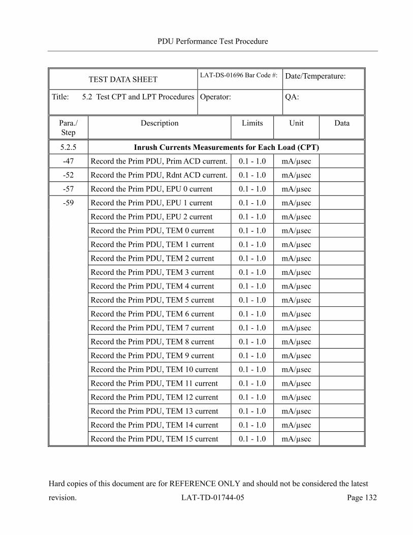
PDU Performance Test Procedure
Hard copies of this document are for REFERENCE ONLY and should not be considered the latest
revision. LAT-TD-01744-05 Page 132
TEST DATA SHEET LAT-DS-01696 Bar Code #:
Date/Temperature:
Title: 5.2 Test CPT and LPT Procedures Operator:
QA:
Para./ Step
Description Limits Unit Data
5.2.5 Inrush Currents Measurements for Each Load (CPT)
-47 Record the Prim PDU, Prim ACD current. 0.1 - 1.0 mA/µsec
-52 Record the Prim PDU, Rdnt ACD current. 0.1 - 1.0 mA/µsec
-57 Record the Prim PDU, EPU 0 current 0.1 - 1.0 mA/µsec
-59 Record the Prim PDU, EPU 1 current 0.1 - 1.0 mA/µsec
Record the Prim PDU, EPU 2 current 0.1 - 1.0 mA/µsec
Record the Prim PDU, TEM 0 current 0.1 - 1.0 mA/µsec
Record the Prim PDU, TEM 1 current 0.1 - 1.0 mA/µsec
Record the Prim PDU, TEM 2 current 0.1 - 1.0 mA/µsec
Record the Prim PDU, TEM 3 current 0.1 - 1.0 mA/µsec
Record the Prim PDU, TEM 4 current 0.1 - 1.0 mA/µsec
Record the Prim PDU, TEM 5 current 0.1 - 1.0 mA/µsec
Record the Prim PDU, TEM 6 current 0.1 - 1.0 mA/µsec
Record the Prim PDU, TEM 7 current 0.1 - 1.0 mA/µsec
Record the Prim PDU, TEM 8 current 0.1 - 1.0 mA/µsec
Record the Prim PDU, TEM 9 current 0.1 - 1.0 mA/µsec
Record the Prim PDU, TEM 10 current 0.1 - 1.0 mA/µsec
Record the Prim PDU, TEM 11 current 0.1 - 1.0 mA/µsec
Record the Prim PDU, TEM 12 current 0.1 - 1.0 mA/µsec
Record the Prim PDU, TEM 13 current 0.1 - 1.0 mA/µsec
Record the Prim PDU, TEM 14 current 0.1 - 1.0 mA/µsec
Record the Prim PDU, TEM 15 current 0.1 - 1.0 mA/µsec

PDU Performance Test Procedure
Hard copies of this document are for REFERENCE ONLY and should not be considered the latest
revision. LAT-TD-01744-05 Page 133
TEST DATA SHEET LAT-DS-01696 Bar Code #:
Date/Temperature:
Title: 5.2 Test CPT and LPT Procedures Operator:
QA:
Para./ Step
Description Limits Unit Data
5.2.5 Inrush Currents Measurements for Each Load (CPT)
-62 Record the Rdnt PDU, Prim ACD current. 0.1 - 1.0 mA/µsec
- Record the Rdnt PDU, Rdnt ACD current. 0.1 - 1.0 mA/µsec
- Record the Rdnt PDU, EPU 0 current 0.1 - 1.0 mA/µsec
Record the Rdnt PDU, EPU 1 current 0.1 - 1.0 mA/µsec
Record the Rdnt PDU, EPU 2 current 0.1 - 1.0 mA/µsec
- Record the Rdnt PDU, TEM 0 current 0.1 - 1.0 mA/µsec
Record the Rdnt PDU, TEM 1 current 0.1 - 1.0 mA/µsec
Record the Rdnt PDU, TEM 2 current 0.1 - 1.0 mA/µsec
Record the Rdnt PDU, TEM 3 current 0.1 - 1.0 mA/µsec
Record the Rdnt PDU, TEM 4 current 0.1 - 1.0 mA/µsec
Record the Rdnt PDU, TEM 5 current 0.1 - 1.0 mA/µsec
Record the Rdnt PDU, TEM 6 current 0.1 - 1.0 mA/µsec
Record the Rdnt PDU, TEM 7 current 0.1 - 1.0 mA/µsec
Record the Rdnt PDU, TEM 8 current 0.1 - 1.0 mA/µsec
Record the Rdnt PDU, TEM 9 current 0.1 - 1.0 mA/µsec
Record the Rdnt PDU, TEM 10 current 0.1 - 1.0 mA/µsec
Record the Rdnt PDU, TEM 11 current 0.1 - 1.0 mA/µsec
Record the Rdnt PDU, TEM 12 current 0.1 - 1.0 mA/µsec
Record the Rdnt PDU, TEM 13 current 0.1 - 1.0 mA/µsec
Record the Rdnt PDU, TEM 14 current 0.1 - 1.0 mA/µsec
Record the Rdnt PDU, TEM 15 current 0.1 - 1.0 mA/µsec

PDU Performance Test Procedure
Hard copies of this document are for REFERENCE ONLY and should not be considered the latest
revision. LAT-TD-01744-05 Page 134
TEST DATA SHEET LAT-DS-01696 Bar Code #:
Date/Temperature:
Title: 5.2 Test CPT and LPT Procedures Operator:
QA:
Para./ Step
Description Limits Unit Data
5.2.5 Inrush Currents Measurements for Each Load (CPT)
67 - a Demate LAT-DS-04309 part A from LAT-DS-05930 P2.
OK OK/NG
67 - b Demate LAT-DS-04309 part BD from LAT-DS-05930 P1.
OK OK/NG
67 - c Mate LAT-DS-04309 part A to LAT-DS-04309 part BD.
OK OK/NG
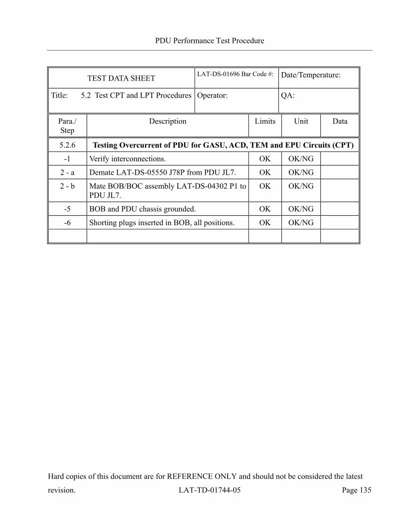
PDU Performance Test Procedure
Hard copies of this document are for REFERENCE ONLY and should not be considered the latest
revision. LAT-TD-01744-05 Page 135
TEST DATA SHEET LAT-DS-01696 Bar Code #:
Date/Temperature:
Title: 5.2 Test CPT and LPT Procedures Operator:
QA:
Para./ Step
Description Limits Unit Data
5.2.6 Testing Overcurrent of PDU for GASU, ACD, TEM and EPU Circuits (CPT)
-1 Verify interconnections. OK OK/NG
2 - a Demate LAT-DS-05550 J78P from PDU JL7. OK OK/NG
2 - b Mate BOB/BOC assembly LAT-DS-04302 P1 to PDU JL7.
OK OK/NG
-5 BOB and PDU chassis grounded. OK OK/NG
-6 Shorting plugs inserted in BOB, all positions. OK OK/NG
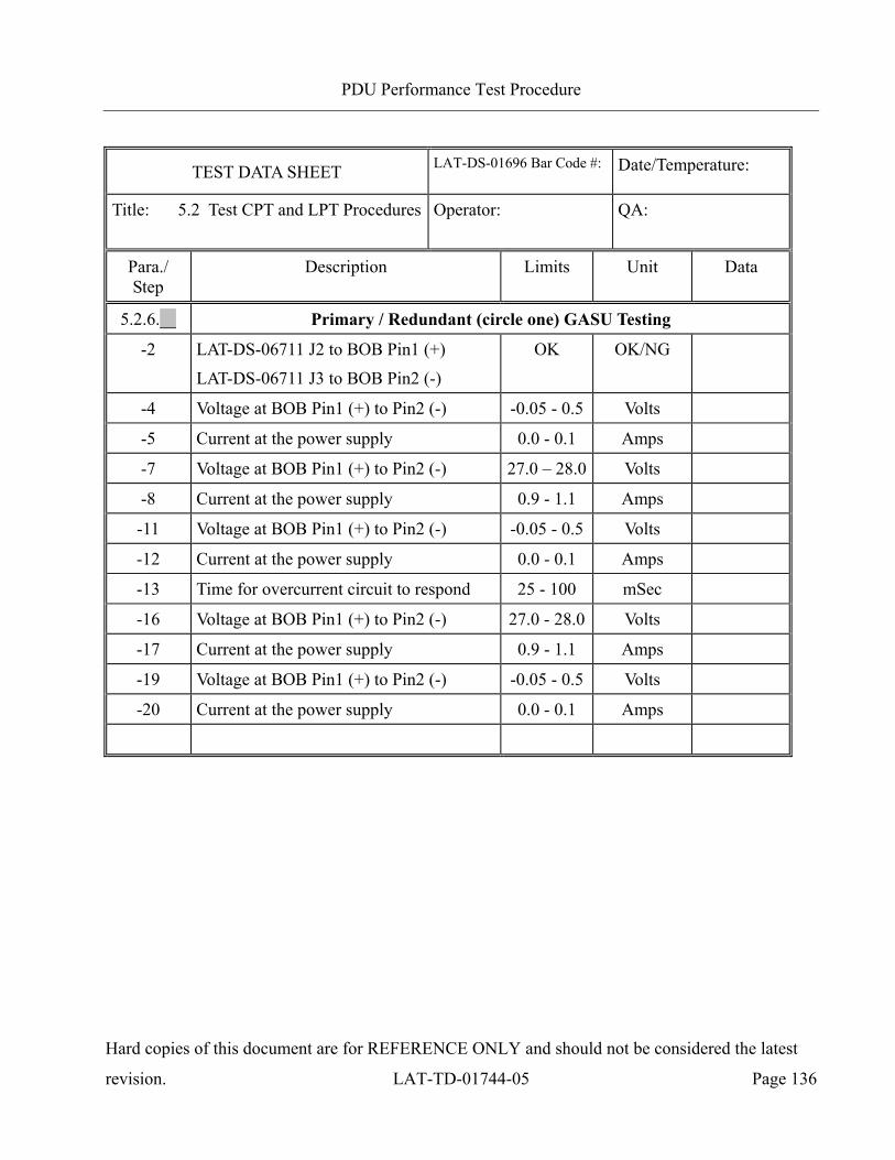
PDU Performance Test Procedure
Hard copies of this document are for REFERENCE ONLY and should not be considered the latest
revision. LAT-TD-01744-05 Page 136
TEST DATA SHEET LAT-DS-01696 Bar Code #:
Date/Temperature:
Title: 5.2 Test CPT and LPT Procedures Operator:
QA:
Para./ Step
Description Limits Unit Data
5.2.6.__ Primary / Redundant (circle one) GASU Testing
-2 LAT-DS-06711 J2 to BOB Pin1 (+)
LAT-DS-06711 J3 to BOB Pin2 (-)
OK OK/NG
-4 Voltage at BOB Pin1 (+) to Pin2 (-) -0.05 - 0.5 Volts
-5 Current at the power supply 0.0 - 0.1 Amps
-7 Voltage at BOB Pin1 (+) to Pin2 (-) 27.0 – 28.0 Volts
-8 Current at the power supply 0.9 - 1.1 Amps
-11 Voltage at BOB Pin1 (+) to Pin2 (-) -0.05 - 0.5 Volts
-12 Current at the power supply 0.0 - 0.1 Amps
-13 Time for overcurrent circuit to respond 25 - 100 mSec
-16 Voltage at BOB Pin1 (+) to Pin2 (-) 27.0 - 28.0 Volts
-17 Current at the power supply 0.9 - 1.1 Amps
-19 Voltage at BOB Pin1 (+) to Pin2 (-) -0.05 - 0.5 Volts
-20 Current at the power supply 0.0 - 0.1 Amps
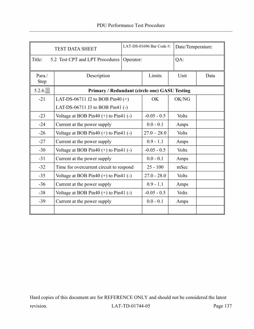
PDU Performance Test Procedure
Hard copies of this document are for REFERENCE ONLY and should not be considered the latest
revision. LAT-TD-01744-05 Page 137
TEST DATA SHEET LAT-DS-01696 Bar Code #:
Date/Temperature:
Title: 5.2 Test CPT and LPT Procedures Operator:
QA:
Para./ Step
Description Limits Unit Data
5.2.6.__ Primary / Redundant (circle one) GASU Testing
-21 LAT-DS-06711 J2 to BOB Pin40 (+)
LAT-DS-06711 J3 to BOB Pin41 (-)
OK OK/NG
-23 Voltage at BOB Pin40 (+) to Pin41 (-) -0.05 - 0.5 Volts
-24 Current at the power supply 0.0 - 0.1 Amps
-26 Voltage at BOB Pin40 (+) to Pin41 (-) 27.0 – 28.0 Volts
-27 Current at the power supply 0.9 - 1.1 Amps
-30 Voltage at BOB Pin40 (+) to Pin41 (-) -0.05 - 0.5 Volts
-31 Current at the power supply 0.0 - 0.1 Amps
-32 Time for overcurrent circuit to respond 25 - 100 mSec
-35 Voltage at BOB Pin40 (+) to Pin41 (-) 27.0 - 28.0 Volts
-36 Current at the power supply 0.9 - 1.1 Amps
-38 Voltage at BOB Pin40 (+) to Pin41 (-) -0.05 - 0.5 Volts
-39 Current at the power supply 0.0 - 0.1 Amps
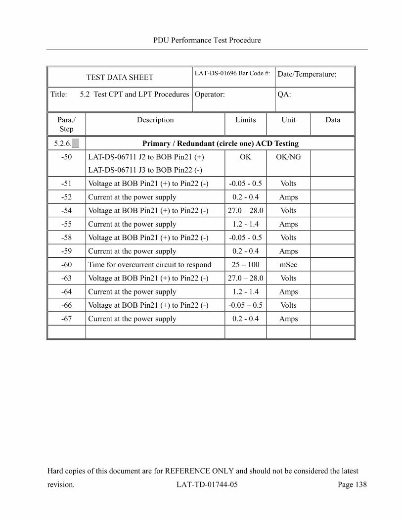
PDU Performance Test Procedure
Hard copies of this document are for REFERENCE ONLY and should not be considered the latest
revision. LAT-TD-01744-05 Page 138
TEST DATA SHEET LAT-DS-01696 Bar Code #:
Date/Temperature:
Title: 5.2 Test CPT and LPT Procedures Operator:
QA:
Para./ Step
Description Limits Unit Data
5.2.6.__ Primary / Redundant (circle one) ACD Testing
-50 LAT-DS-06711 J2 to BOB Pin21 (+)
LAT-DS-06711 J3 to BOB Pin22 (-)
OK OK/NG
-51 Voltage at BOB Pin21 (+) to Pin22 (-) -0.05 - 0.5 Volts
-52 Current at the power supply 0.2 - 0.4 Amps
-54 Voltage at BOB Pin21 (+) to Pin22 (-) 27.0 – 28.0 Volts
-55 Current at the power supply 1.2 - 1.4 Amps
-58 Voltage at BOB Pin21 (+) to Pin22 (-) -0.05 - 0.5 Volts
-59 Current at the power supply 0.2 - 0.4 Amps
-60 Time for overcurrent circuit to respond 25 – 100 mSec
-63 Voltage at BOB Pin21 (+) to Pin22 (-) 27.0 – 28.0 Volts
-64 Current at the power supply 1.2 - 1.4 Amps
-66 Voltage at BOB Pin21 (+) to Pin22 (-) -0.05 – 0.5 Volts
-67 Current at the power supply 0.2 - 0.4 Amps
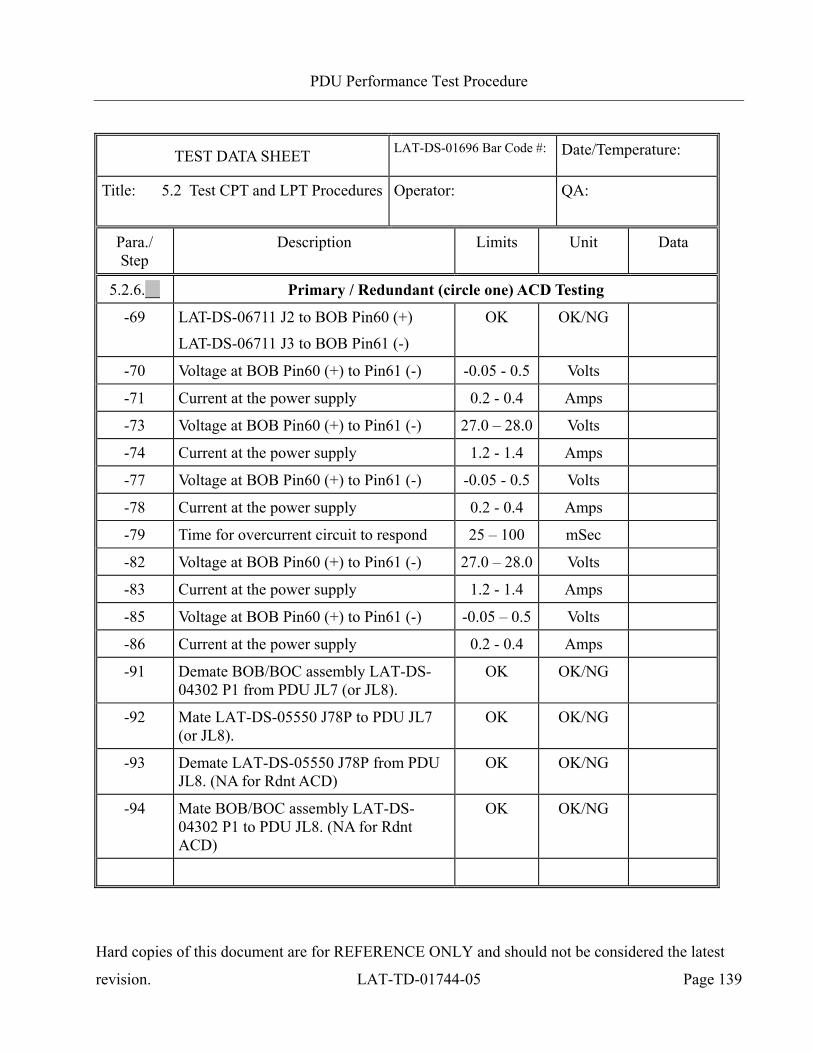
PDU Performance Test Procedure
Hard copies of this document are for REFERENCE ONLY and should not be considered the latest
revision. LAT-TD-01744-05 Page 139
TEST DATA SHEET LAT-DS-01696 Bar Code #:
Date/Temperature:
Title: 5.2 Test CPT and LPT Procedures Operator:
QA:
Para./ Step
Description Limits Unit Data
5.2.6.__ Primary / Redundant (circle one) ACD Testing
-69 LAT-DS-06711 J2 to BOB Pin60 (+)
LAT-DS-06711 J3 to BOB Pin61 (-)
OK OK/NG
-70 Voltage at BOB Pin60 (+) to Pin61 (-) -0.05 - 0.5 Volts
-71 Current at the power supply 0.2 - 0.4 Amps
-73 Voltage at BOB Pin60 (+) to Pin61 (-) 27.0 – 28.0 Volts
-74 Current at the power supply 1.2 - 1.4 Amps
-77 Voltage at BOB Pin60 (+) to Pin61 (-) -0.05 - 0.5 Volts
-78 Current at the power supply 0.2 - 0.4 Amps
-79 Time for overcurrent circuit to respond 25 – 100 mSec
-82 Voltage at BOB Pin60 (+) to Pin61 (-) 27.0 – 28.0 Volts
-83 Current at the power supply 1.2 - 1.4 Amps
-85 Voltage at BOB Pin60 (+) to Pin61 (-) -0.05 – 0.5 Volts
-86 Current at the power supply 0.2 - 0.4 Amps
-91 Demate BOB/BOC assembly LAT-DS-04302 P1 from PDU JL7 (or JL8).
OK OK/NG
-92 Mate LAT-DS-05550 J78P to PDU JL7 (or JL8).
OK OK/NG
-93 Demate LAT-DS-05550 J78P from PDU JL8. (NA for Rdnt ACD)
OK OK/NG
-94 Mate BOB/BOC assembly LAT-DS-04302 P1 to PDU JL8. (NA for Rdnt ACD)
OK OK/NG
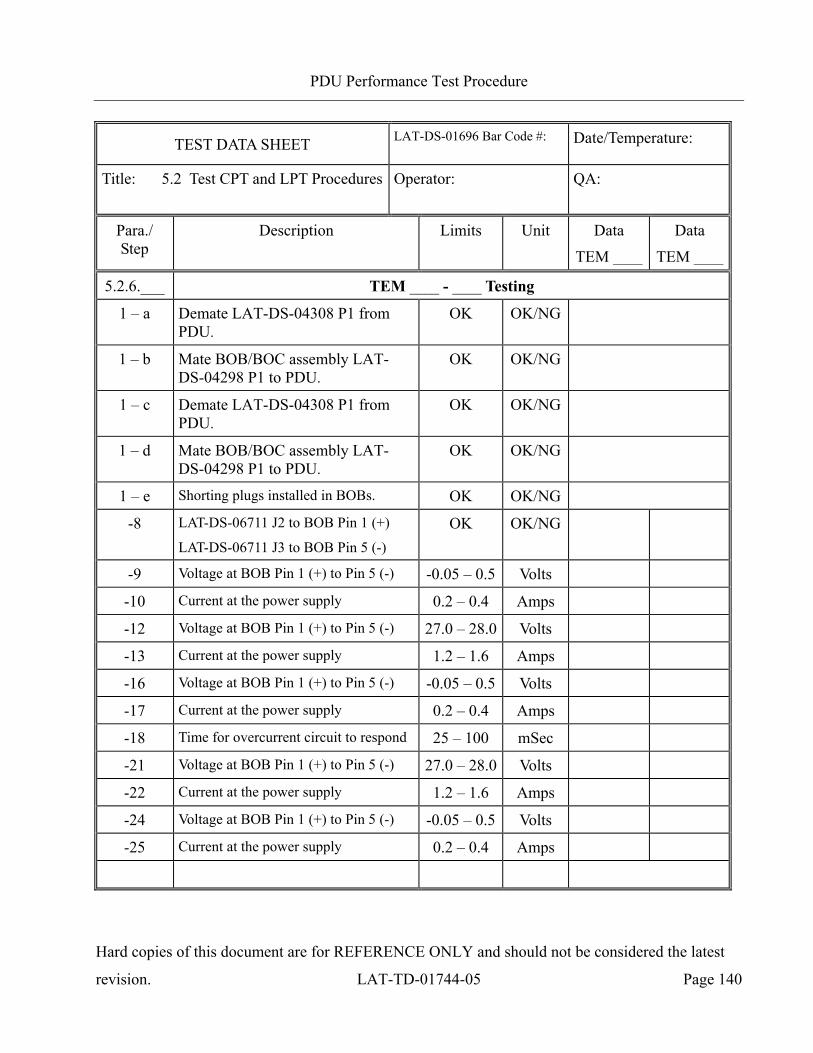
PDU Performance Test Procedure
Hard copies of this document are for REFERENCE ONLY and should not be considered the latest
revision. LAT-TD-01744-05 Page 140
TEST DATA SHEET LAT-DS-01696 Bar Code #:
Date/Temperature:
Title: 5.2 Test CPT and LPT Procedures Operator:
QA:
Para./ Step
Description Limits Unit Data
TEM ____
Data
TEM ____
5.2.6.___ TEM ____ - ____ Testing
1 – a Demate LAT-DS-04308 P1 from PDU.
OK OK/NG
1 – b Mate BOB/BOC assembly LAT-DS-04298 P1 to PDU.
OK OK/NG
1 – c Demate LAT-DS-04308 P1 from PDU.
OK OK/NG
1 – d Mate BOB/BOC assembly LAT-DS-04298 P1 to PDU.
OK OK/NG
1 – e Shorting plugs installed in BOBs. OK OK/NG
-8 LAT-DS-06711 J2 to BOB Pin 1 (+)
LAT-DS-06711 J3 to BOB Pin 5 (-) OK OK/NG
-9 Voltage at BOB Pin 1 (+) to Pin 5 (-) -0.05 – 0.5 Volts
-10 Current at the power supply 0.2 – 0.4 Amps
-12 Voltage at BOB Pin 1 (+) to Pin 5 (-) 27.0 – 28.0 Volts
-13 Current at the power supply 1.2 – 1.6 Amps
-16 Voltage at BOB Pin 1 (+) to Pin 5 (-) -0.05 – 0.5 Volts
-17 Current at the power supply 0.2 – 0.4 Amps
-18 Time for overcurrent circuit to respond 25 – 100 mSec
-21 Voltage at BOB Pin 1 (+) to Pin 5 (-) 27.0 – 28.0 Volts
-22 Current at the power supply 1.2 – 1.6 Amps
-24 Voltage at BOB Pin 1 (+) to Pin 5 (-) -0.05 – 0.5 Volts
-25 Current at the power supply 0.2 – 0.4 Amps
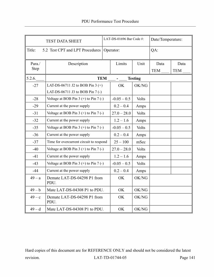
PDU Performance Test Procedure
Hard copies of this document are for REFERENCE ONLY and should not be considered the latest
revision. LAT-TD-01744-05 Page 141
TEST DATA SHEET LAT-DS-01696 Bar Code #:
Date/Temperature:
Title: 5.2 Test CPT and LPT Procedures Operator:
QA:
Para./ Step
Description Limits Unit Data
TEM ____
Data
TEM ____
5.2.6.____ TEM ____ - ____ Testing
-27 LAT-DS-06711 J2 to BOB Pin 3 (+)
LAT-DS-06711 J3 to BOB Pin 7 (-) OK OK/NG
-28 Voltage at BOB Pin 3 (+) to Pin 7 (-) -0.05 – 0.5 Volts
-29 Current at the power supply 0.2 – 0.4 Amps
-31 Voltage at BOB Pin 3 (+) to Pin 7 (-) 27.0 – 28.0 Volts
-32 Current at the power supply 1.2 – 1.6 Amps
-35 Voltage at BOB Pin 3 (+) to Pin 7 (-) -0.05 – 0.5 Volts
-36 Current at the power supply 0.2 – 0.4 Amps
-37 Time for overcurrent circuit to respond 25 – 100 mSec
-40 Voltage at BOB Pin 3 (+) to Pin 7 (-) 27.0 – 28.0 Volts
-41 Current at the power supply 1.2 – 1.6 Amps
-43 Voltage at BOB Pin 3 (+) to Pin 7 (-) -0.05 – 0.5 Volts
-44 Current at the power supply 0.2 – 0.4 Amps
49 – a Demate LAT-DS-04298 P1 from PDU.
OK OK/NG
49 – b Mate LAT-DS-04308 P1 to PDU. OK OK/NG
49 – c Demate LAT-DS-04298 P1 from PDU.
OK OK/NG
49 – d Mate LAT-DS-04308 P1 to PDU. OK OK/NG
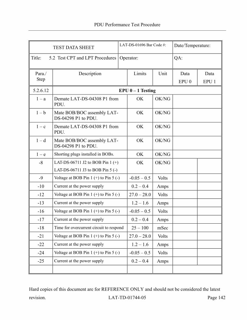
PDU Performance Test Procedure
Hard copies of this document are for REFERENCE ONLY and should not be considered the latest
revision. LAT-TD-01744-05 Page 142
TEST DATA SHEET LAT-DS-01696 Bar Code #:
Date/Temperature:
Title: 5.2 Test CPT and LPT Procedures Operator:
QA:
Para./ Step
Description Limits Unit Data
EPU 0
Data
EPU 1
5.2.6.12 EPU 0 – 1 Testing
1 – a Demate LAT-DS-04308 P1 from PDU.
OK OK/NG
1 – b Mate BOB/BOC assembly LAT-DS-04298 P1 to PDU.
OK OK/NG
1 – c Demate LAT-DS-04308 P1 from PDU.
OK OK/NG
1 – d Mate BOB/BOC assembly LAT-DS-04298 P1 to PDU.
OK OK/NG
1 – e Shorting plugs installed in BOBs. OK OK/NG
-8 LAT-DS-06711 J2 to BOB Pin 1 (+)
LAT-DS-06711 J3 to BOB Pin 5 (-) OK OK/NG
-9 Voltage at BOB Pin 1 (+) to Pin 5 (-) -0.05 – 0.5 Volts
-10 Current at the power supply 0.2 – 0.4 Amps
-12 Voltage at BOB Pin 1 (+) to Pin 5 (-) 27.0 – 28.0 Volts
-13 Current at the power supply 1.2 – 1.6 Amps
-16 Voltage at BOB Pin 1 (+) to Pin 5 (-) -0.05 – 0.5 Volts
-17 Current at the power supply 0.2 – 0.4 Amps
-18 Time for overcurrent circuit to respond 25 – 100 mSec
-21 Voltage at BOB Pin 1 (+) to Pin 5 (-) 27.0 – 28.0 Volts
-22 Current at the power supply 1.2 – 1.6 Amps
-24 Voltage at BOB Pin 1 (+) to Pin 5 (-) -0.05 – 0.5 Volts
-25 Current at the power supply 0.2 – 0.4 Amps

PDU Performance Test Procedure
Hard copies of this document are for REFERENCE ONLY and should not be considered the latest
revision. LAT-TD-01744-05 Page 143
TEST DATA SHEET LAT-DS-01696 Bar Code #:
Date/Temperature:
Title: 5.2 Test CPT and LPT Procedures Operator:
QA:
Para./ Step
Description Limits Unit Data
EPU 0
Data
EPU 1
5.2.6.12 EPU 0 – 1 Testing
-27 LAT-DS-06711 J2 to BOB Pin 3 (+)
LAT-DS-06711 J3 to BOB Pin 7 (-) OK OK/NG
-28 Voltage at BOB Pin 3 (+) to Pin 7 (-) -0.05 – 0.5 Volts
-29 Current at the power supply 0.2 – 0.4 Amps
-31 Voltage at BOB Pin 3 (+) to Pin 7 (-) 27.0 – 28.0 Volts
-32 Current at the power supply 1.2 – 1.6 Amps
-35 Voltage at BOB Pin 3 (+) to Pin 7 (-) -0.05 – 0.5 Volts
-36 Current at the power supply 0.2 – 0.4 Amps
-37 Time for overcurrent circuit to respond 25 – 100 mSec
-40 Voltage at BOB Pin 3 (+) to Pin 7 (-) 27.0 – 28.0 Volts
-41 Current at the power supply 1.2 – 1.6 Amps
-43 Voltage at BOB Pin 3 (+) to Pin 7 (-) -0.05 – 0.5 Volts
-44 Current at the power supply 0.2 – 0.4 Amps
49 – a Demate LAT-DS-04298 P1 from PDU.
OK OK/NG
49 – b Mate LAT-DS-04308 P1 to PDU. OK OK/NG
49 – c Demate LAT-DS-04298 P1 from PDU.
OK OK/NG
49 – d Mate LAT-DS-04308 P1 to PDU. OK OK/NG
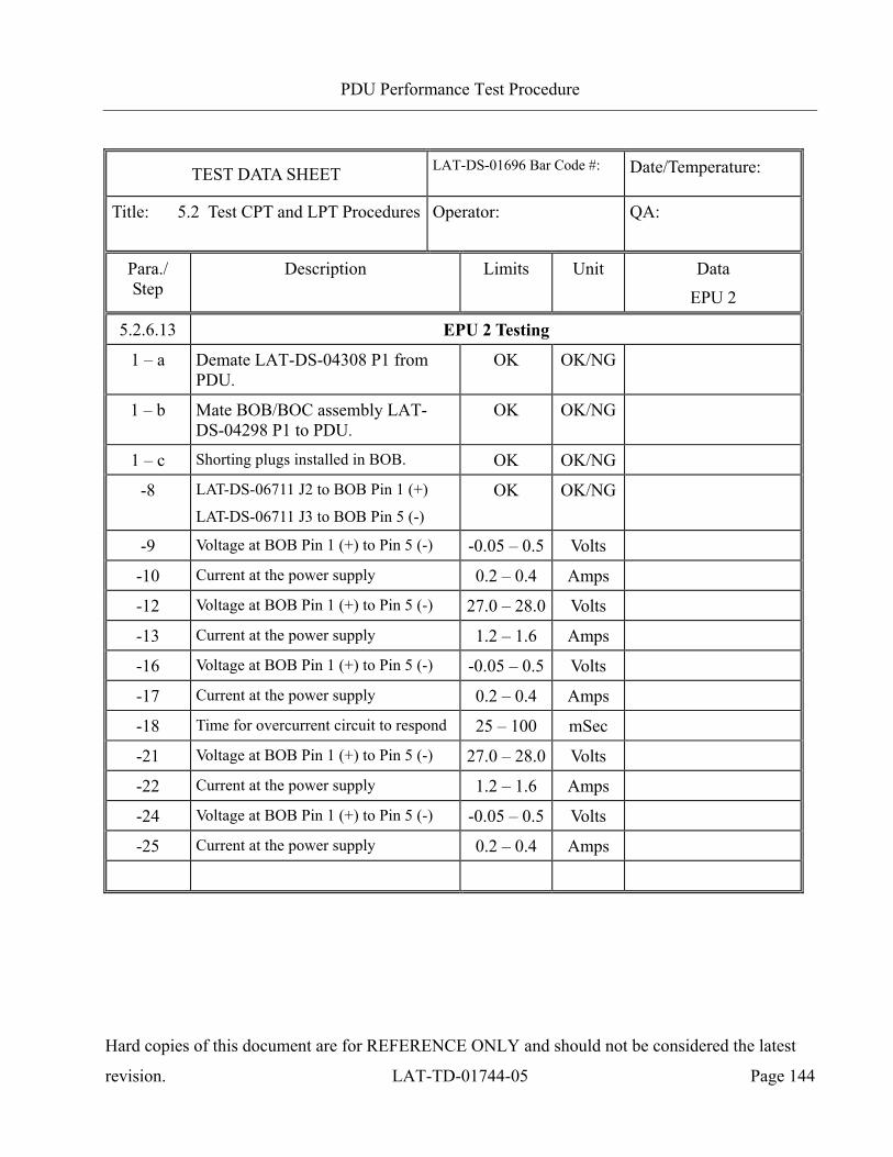
PDU Performance Test Procedure
Hard copies of this document are for REFERENCE ONLY and should not be considered the latest
revision. LAT-TD-01744-05 Page 144
TEST DATA SHEET LAT-DS-01696 Bar Code #:
Date/Temperature:
Title: 5.2 Test CPT and LPT Procedures Operator:
QA:
Para./ Step
Description Limits Unit Data
EPU 2
5.2.6.13 EPU 2 Testing
1 – a Demate LAT-DS-04308 P1 from PDU.
OK OK/NG
1 – b Mate BOB/BOC assembly LAT-DS-04298 P1 to PDU.
OK OK/NG
1 – c Shorting plugs installed in BOB. OK OK/NG
-8 LAT-DS-06711 J2 to BOB Pin 1 (+)
LAT-DS-06711 J3 to BOB Pin 5 (-) OK OK/NG
-9 Voltage at BOB Pin 1 (+) to Pin 5 (-) -0.05 – 0.5 Volts
-10 Current at the power supply 0.2 – 0.4 Amps
-12 Voltage at BOB Pin 1 (+) to Pin 5 (-) 27.0 – 28.0 Volts
-13 Current at the power supply 1.2 – 1.6 Amps
-16 Voltage at BOB Pin 1 (+) to Pin 5 (-) -0.05 – 0.5 Volts
-17 Current at the power supply 0.2 – 0.4 Amps
-18 Time for overcurrent circuit to respond 25 – 100 mSec
-21 Voltage at BOB Pin 1 (+) to Pin 5 (-) 27.0 – 28.0 Volts
-22 Current at the power supply 1.2 – 1.6 Amps
-24 Voltage at BOB Pin 1 (+) to Pin 5 (-) -0.05 – 0.5 Volts
-25 Current at the power supply 0.2 – 0.4 Amps
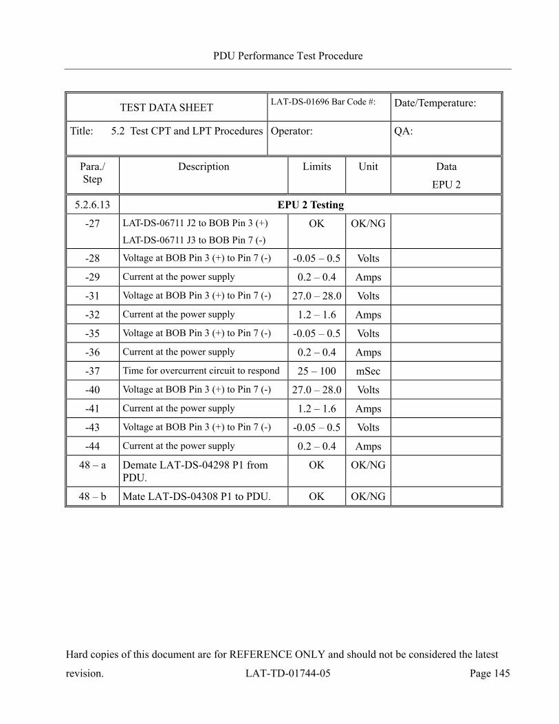
PDU Performance Test Procedure
Hard copies of this document are for REFERENCE ONLY and should not be considered the latest
revision. LAT-TD-01744-05 Page 145
TEST DATA SHEET LAT-DS-01696 Bar Code #:
Date/Temperature:
Title: 5.2 Test CPT and LPT Procedures Operator:
QA:
Para./ Step
Description Limits Unit Data
EPU 2
5.2.6.13 EPU 2 Testing
-27 LAT-DS-06711 J2 to BOB Pin 3 (+)
LAT-DS-06711 J3 to BOB Pin 7 (-) OK OK/NG
-28 Voltage at BOB Pin 3 (+) to Pin 7 (-) -0.05 – 0.5 Volts
-29 Current at the power supply 0.2 – 0.4 Amps
-31 Voltage at BOB Pin 3 (+) to Pin 7 (-) 27.0 – 28.0 Volts
-32 Current at the power supply 1.2 – 1.6 Amps
-35 Voltage at BOB Pin 3 (+) to Pin 7 (-) -0.05 – 0.5 Volts
-36 Current at the power supply 0.2 – 0.4 Amps
-37 Time for overcurrent circuit to respond 25 – 100 mSec
-40 Voltage at BOB Pin 3 (+) to Pin 7 (-) 27.0 – 28.0 Volts
-41 Current at the power supply 1.2 – 1.6 Amps
-43 Voltage at BOB Pin 3 (+) to Pin 7 (-) -0.05 – 0.5 Volts
-44 Current at the power supply 0.2 – 0.4 Amps
48 – a Demate LAT-DS-04298 P1 from PDU.
OK OK/NG
48 – b Mate LAT-DS-04308 P1 to PDU. OK OK/NG

PDU Performance Test Procedure
Hard copies of this document are for REFERENCE ONLY and should not be considered the latest
revision. LAT-TD-01744-05 Page 146
TEST DATA SHEET LAT-DS-01696 Bar Code #:
Date/Temperature:
Title: 5.2 Test CPT and LPT Procedures Operator:
QA:
Para./ Step
Description Limits Unit Data
5.2.7 Testing the Power Consumption of the PDU (CPT)
-1 Resistance of LAT-DS-04309 cable used in this section.
NA Ohms
-2 Record the GLAT serial number.
-3 Verify the test stand configuration. OK OK/NG
4 - a Demate LAT-DS-05550 J78P from PDU JL7. OK OK/NG
4 - b Mate LAT-DS-04302 P1 to PDU JL7. OK OK/NG
-7 Remove the shorting plugs from the JL7 BOB on pins 1 and 3.
OK OK/NG
-8 The ammeter setup on the BOB is complete. OK OK/NG
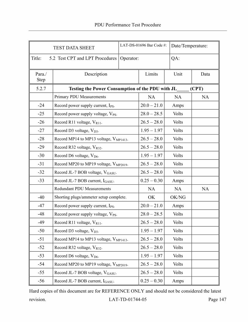
PDU Performance Test Procedure
Hard copies of this document are for REFERENCE ONLY and should not be considered the latest
revision. LAT-TD-01744-05 Page 147
TEST DATA SHEET LAT-DS-01696 Bar Code #:
Date/Temperature:
Title: 5.2 Test CPT and LPT Procedures Operator:
QA:
Para./ Step
Description Limits Unit Data
5.2.7 Testing the Power Consumption of the PDU with JL_____ (CPT)
Primary PDU Measurements NA NA NA
-24 Record power supply current, IPS. 20.0 – 21.0 Amps
-25 Record power supply voltage, VPS. 28.0 – 28.5 Volts
-26 Record R11 voltage, VR11. 26.5 – 28.0 Volts
-27 Record D3 voltage, VD3. 1.95 – 1.97 Volts
-28 Record MP14 to MP13 voltage, VMP1413. 26.5 – 28.0 Volts
-29 Record R32 voltage, VR32. 26.5 – 28.0 Volts
-30 Record D6 voltage, VD6. 1.95 – 1.97 Volts
-31 Record MP20 to MP19 voltage, VMP2019. 26.5 – 28.0 Volts
-32 Record JL-7 BOB voltage, VGASU. 26.5 – 28.0 Volts
-33 Record JL-7 BOB current, IGASU. 0.25 – 0.30 Amps
Redundant PDU Measurements NA NA NA
-40 Shorting plugs/ammeter setup complete. OK OK/NG
-47 Record power supply current, IPS. 20.0 – 21.0 Amps
-48 Record power supply voltage, VPS. 28.0 – 28.5 Volts
-49 Record R11 voltage, VR11. 26.5 – 28.0 Volts
-50 Record D3 voltage, VD3. 1.95 – 1.97 Volts
-51 Record MP14 to MP13 voltage, VMP1413. 26.5 – 28.0 Volts
-52 Record R32 voltage, VR32. 26.5 – 28.0 Volts
-53 Record D6 voltage, VD6. 1.95 – 1.97 Volts
-54 Record MP20 to MP19 voltage, VMP2019. 26.5 – 28.0 Volts
-55 Record JL-7 BOB voltage, VGASU. 26.5 – 28.0 Volts
-56 Record JL-7 BOB current, IGASU. 0.25 – 0.30 Amps
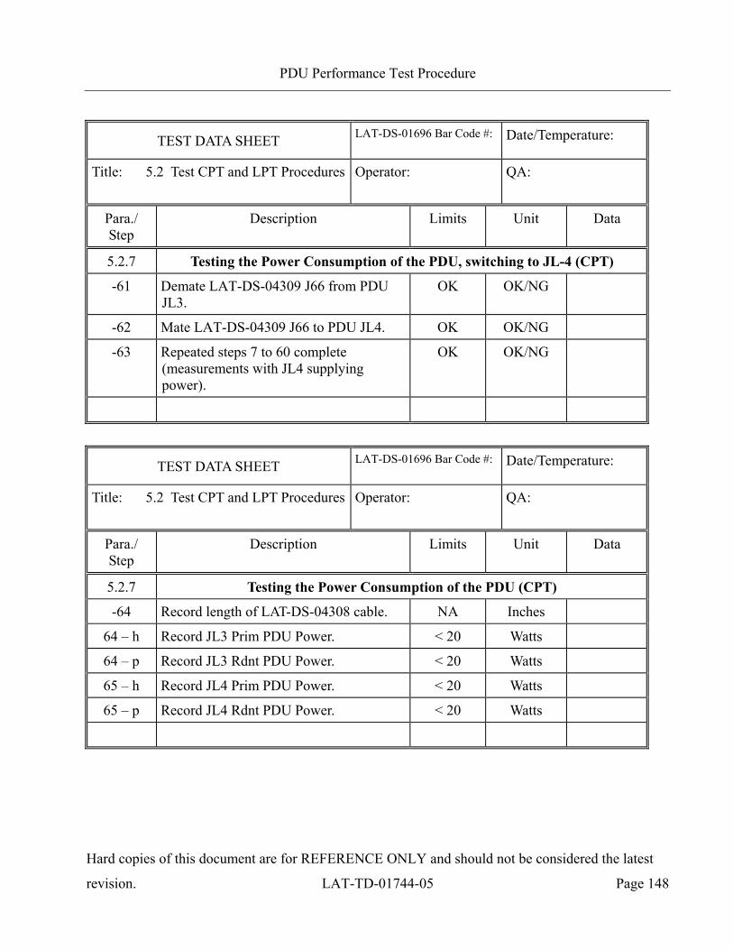
PDU Performance Test Procedure
Hard copies of this document are for REFERENCE ONLY and should not be considered the latest
revision. LAT-TD-01744-05 Page 148
TEST DATA SHEET LAT-DS-01696 Bar Code #:
Date/Temperature:
Title: 5.2 Test CPT and LPT Procedures Operator:
QA:
Para./ Step
Description Limits Unit Data
5.2.7 Testing the Power Consumption of the PDU, switching to JL-4 (CPT)
-61 Demate LAT-DS-04309 J66 from PDU JL3.
OK OK/NG
-62 Mate LAT-DS-04309 J66 to PDU JL4. OK OK/NG
-63 Repeated steps 7 to 60 complete (measurements with JL4 supplying power).
OK OK/NG
TEST DATA SHEET LAT-DS-01696 Bar Code #:
Date/Temperature:
Title: 5.2 Test CPT and LPT Procedures Operator:
QA:
Para./ Step
Description Limits Unit Data
5.2.7 Testing the Power Consumption of the PDU (CPT)
-64 Record length of LAT-DS-04308 cable. NA Inches
64 – h Record JL3 Prim PDU Power. < 20 Watts
64 – p Record JL3 Rdnt PDU Power. < 20 Watts
65 – h Record JL4 Prim PDU Power. < 20 Watts
65 – p Record JL4 Rdnt PDU Power. < 20 Watts
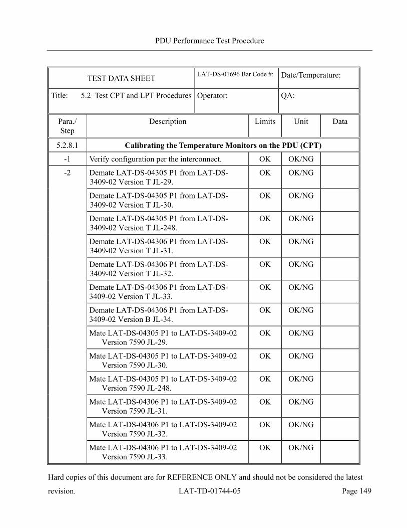
PDU Performance Test Procedure
Hard copies of this document are for REFERENCE ONLY and should not be considered the latest
revision. LAT-TD-01744-05 Page 149
TEST DATA SHEET LAT-DS-01696 Bar Code #:
Date/Temperature:
Title: 5.2 Test CPT and LPT Procedures Operator:
QA:
Para./ Step
Description Limits Unit Data
5.2.8.1 Calibrating the Temperature Monitors on the PDU (CPT)
-1 Verify configuration per the interconnect. OK OK/NG
-2 Demate LAT-DS-04305 P1 from LAT-DS-3409-02 Version T JL-29.
OK OK/NG
Demate LAT-DS-04305 P1 from LAT-DS-3409-02 Version T JL-30.
OK OK/NG
Demate LAT-DS-04305 P1 from LAT-DS-3409-02 Version T JL-248.
OK OK/NG
Demate LAT-DS-04306 P1 from LAT-DS-3409-02 Version T JL-31.
OK OK/NG
Demate LAT-DS-04306 P1 from LAT-DS-3409-02 Version T JL-32.
OK OK/NG
Demate LAT-DS-04306 P1 from LAT-DS-3409-02 Version T JL-33.
OK OK/NG
Demate LAT-DS-04306 P1 from LAT-DS-3409-02 Version B JL-34.
OK OK/NG
Mate LAT-DS-04305 P1 to LAT-DS-3409-02 Version 7590 JL-29.
OK OK/NG
Mate LAT-DS-04305 P1 to LAT-DS-3409-02 Version 7590 JL-30.
OK OK/NG
Mate LAT-DS-04305 P1 to LAT-DS-3409-02 Version 7590 JL-248.
OK OK/NG
Mate LAT-DS-04306 P1 to LAT-DS-3409-02 Version 7590 JL-31.
OK OK/NG
Mate LAT-DS-04306 P1 to LAT-DS-3409-02 Version 7590 JL-32.
OK OK/NG
Mate LAT-DS-04306 P1 to LAT-DS-3409-02 Version 7590 JL-33.
OK OK/NG
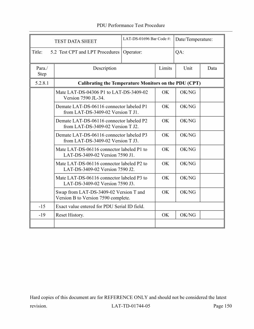
PDU Performance Test Procedure
Hard copies of this document are for REFERENCE ONLY and should not be considered the latest
revision. LAT-TD-01744-05 Page 150
TEST DATA SHEET LAT-DS-01696 Bar Code #:
Date/Temperature:
Title: 5.2 Test CPT and LPT Procedures Operator:
QA:
Para./ Step
Description Limits Unit Data
5.2.8.1 Calibrating the Temperature Monitors on the PDU (CPT)
Mate LAT-DS-04306 P1 to LAT-DS-3409-02 Version 7590 JL-34.
OK OK/NG
Demate LAT-DS-06116 connector labeled P1 from LAT-DS-3409-02 Version T J1.
OK OK/NG
Demate LAT-DS-06116 connector labeled P2 from LAT-DS-3409-02 Version T J2.
OK OK/NG
Demate LAT-DS-06116 connector labeled P3 from LAT-DS-3409-02 Version T J3.
OK OK/NG
Mate LAT-DS-06116 connector labeled P1 to LAT-DS-3409-02 Version 7590 J1.
OK OK/NG
Mate LAT-DS-06116 connector labeled P2 to LAT-DS-3409-02 Version 7590 J2.
OK OK/NG
Mate LAT-DS-06116 connector labeled P3 to LAT-DS-3409-02 Version 7590 J3.
OK OK/NG
Swap from LAT-DS-3409-02 Version T and Version B to Version 7590 complete.
OK OK/NG
-15 Exact value entered for PDU Serial ID field.
-19 Reset History. OK OK/NG
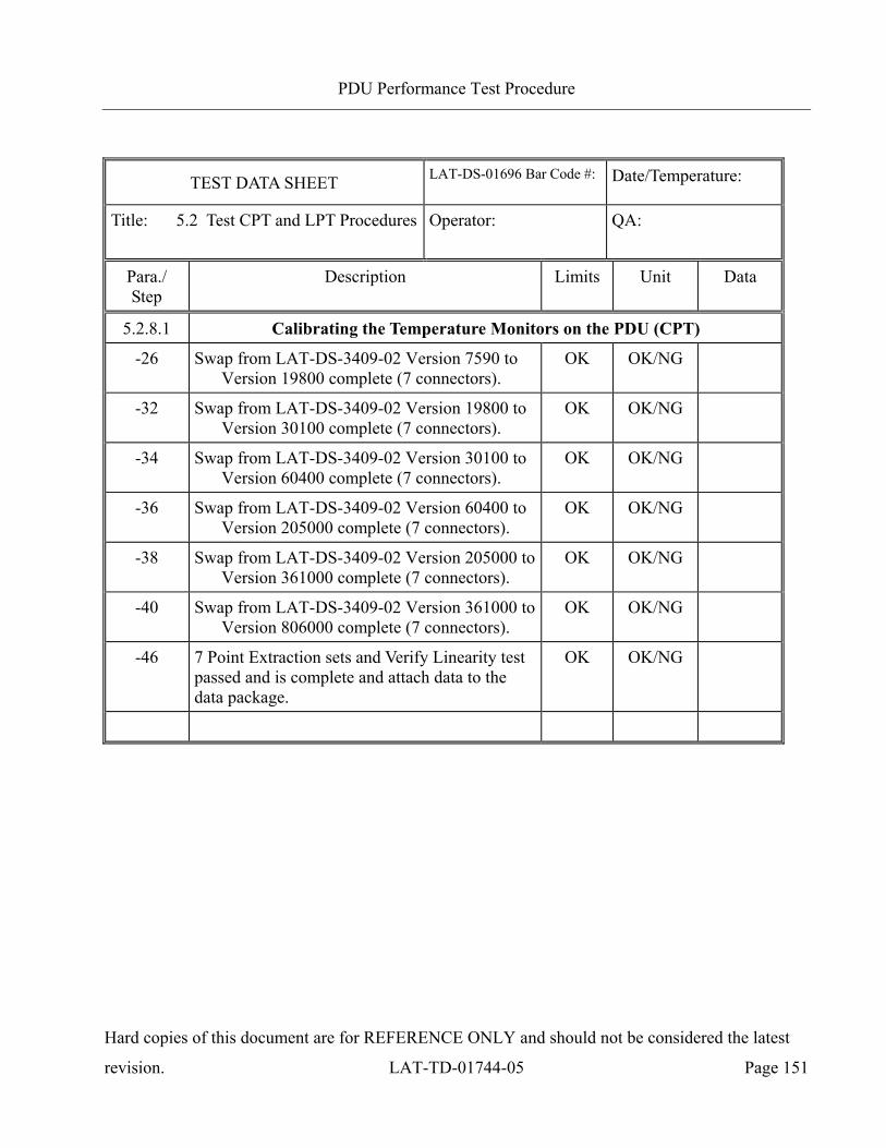
PDU Performance Test Procedure
Hard copies of this document are for REFERENCE ONLY and should not be considered the latest
revision. LAT-TD-01744-05 Page 151
TEST DATA SHEET LAT-DS-01696 Bar Code #:
Date/Temperature:
Title: 5.2 Test CPT and LPT Procedures Operator:
QA:
Para./ Step
Description Limits Unit Data
5.2.8.1 Calibrating the Temperature Monitors on the PDU (CPT)
-26 Swap from LAT-DS-3409-02 Version 7590 to Version 19800 complete (7 connectors).
OK OK/NG
-32 Swap from LAT-DS-3409-02 Version 19800 to Version 30100 complete (7 connectors).
OK OK/NG
-34 Swap from LAT-DS-3409-02 Version 30100 to Version 60400 complete (7 connectors).
OK OK/NG
-36 Swap from LAT-DS-3409-02 Version 60400 to Version 205000 complete (7 connectors).
OK OK/NG
-38 Swap from LAT-DS-3409-02 Version 205000 to Version 361000 complete (7 connectors).
OK OK/NG
-40 Swap from LAT-DS-3409-02 Version 361000 to Version 806000 complete (7 connectors).
OK OK/NG
-46 7 Point Extraction sets and Verify Linearity test passed and is complete and attach data to the data package.
OK OK/NG
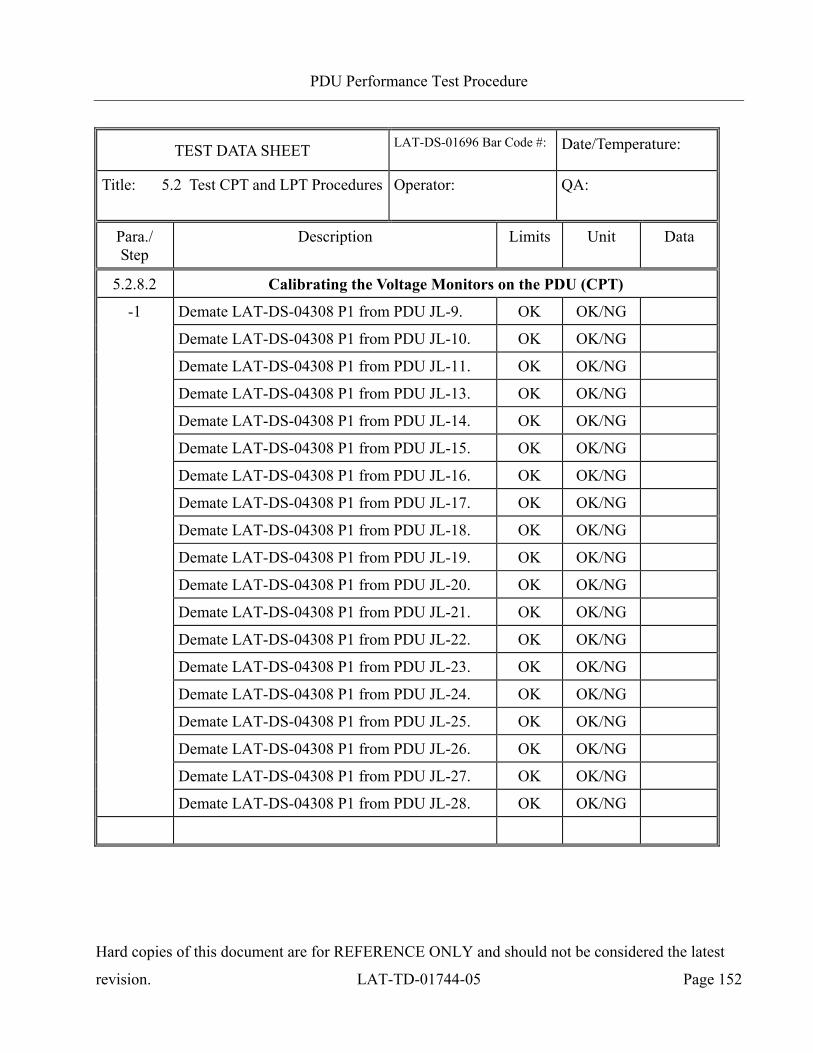
PDU Performance Test Procedure
Hard copies of this document are for REFERENCE ONLY and should not be considered the latest
revision. LAT-TD-01744-05 Page 152
TEST DATA SHEET LAT-DS-01696 Bar Code #:
Date/Temperature:
Title: 5.2 Test CPT and LPT Procedures Operator:
QA:
Para./ Step
Description Limits Unit Data
5.2.8.2 Calibrating the Voltage Monitors on the PDU (CPT)
-1 Demate LAT-DS-04308 P1 from PDU JL-9. OK OK/NG
Demate LAT-DS-04308 P1 from PDU JL-10. OK OK/NG
Demate LAT-DS-04308 P1 from PDU JL-11. OK OK/NG
Demate LAT-DS-04308 P1 from PDU JL-13. OK OK/NG
Demate LAT-DS-04308 P1 from PDU JL-14. OK OK/NG
Demate LAT-DS-04308 P1 from PDU JL-15. OK OK/NG
Demate LAT-DS-04308 P1 from PDU JL-16. OK OK/NG
Demate LAT-DS-04308 P1 from PDU JL-17. OK OK/NG
Demate LAT-DS-04308 P1 from PDU JL-18. OK OK/NG
Demate LAT-DS-04308 P1 from PDU JL-19. OK OK/NG
Demate LAT-DS-04308 P1 from PDU JL-20. OK OK/NG
Demate LAT-DS-04308 P1 from PDU JL-21. OK OK/NG
Demate LAT-DS-04308 P1 from PDU JL-22. OK OK/NG
Demate LAT-DS-04308 P1 from PDU JL-23. OK OK/NG
Demate LAT-DS-04308 P1 from PDU JL-24. OK OK/NG
Demate LAT-DS-04308 P1 from PDU JL-25. OK OK/NG
Demate LAT-DS-04308 P1 from PDU JL-26. OK OK/NG
Demate LAT-DS-04308 P1 from PDU JL-27. OK OK/NG
Demate LAT-DS-04308 P1 from PDU JL-28. OK OK/NG
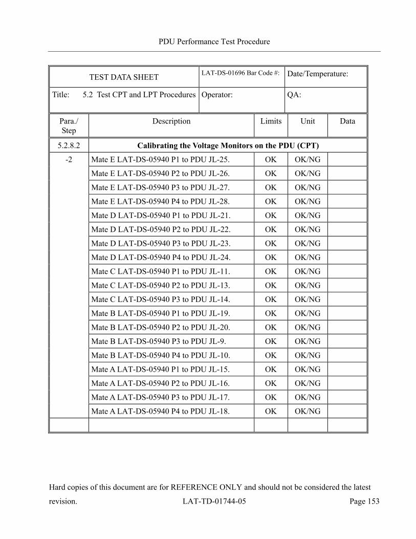
PDU Performance Test Procedure
Hard copies of this document are for REFERENCE ONLY and should not be considered the latest
revision. LAT-TD-01744-05 Page 153
TEST DATA SHEET LAT-DS-01696 Bar Code #:
Date/Temperature:
Title: 5.2 Test CPT and LPT Procedures Operator:
QA:
Para./ Step
Description Limits Unit Data
5.2.8.2 Calibrating the Voltage Monitors on the PDU (CPT)
-2 Mate E LAT-DS-05940 P1 to PDU JL-25. OK OK/NG
Mate E LAT-DS-05940 P2 to PDU JL-26. OK OK/NG
Mate E LAT-DS-05940 P3 to PDU JL-27. OK OK/NG
Mate E LAT-DS-05940 P4 to PDU JL-28. OK OK/NG
Mate D LAT-DS-05940 P1 to PDU JL-21. OK OK/NG
Mate D LAT-DS-05940 P2 to PDU JL-22. OK OK/NG
Mate D LAT-DS-05940 P3 to PDU JL-23. OK OK/NG
Mate D LAT-DS-05940 P4 to PDU JL-24. OK OK/NG
Mate C LAT-DS-05940 P1 to PDU JL-11. OK OK/NG
Mate C LAT-DS-05940 P2 to PDU JL-13. OK OK/NG
Mate C LAT-DS-05940 P3 to PDU JL-14. OK OK/NG
Mate B LAT-DS-05940 P1 to PDU JL-19. OK OK/NG
Mate B LAT-DS-05940 P2 to PDU JL-20. OK OK/NG
Mate B LAT-DS-05940 P3 to PDU JL-9. OK OK/NG
Mate B LAT-DS-05940 P4 to PDU JL-10. OK OK/NG
Mate A LAT-DS-05940 P1 to PDU JL-15. OK OK/NG
Mate A LAT-DS-05940 P2 to PDU JL-16. OK OK/NG
Mate A LAT-DS-05940 P3 to PDU JL-17. OK OK/NG
Mate A LAT-DS-05940 P4 to PDU JL-18. OK OK/NG
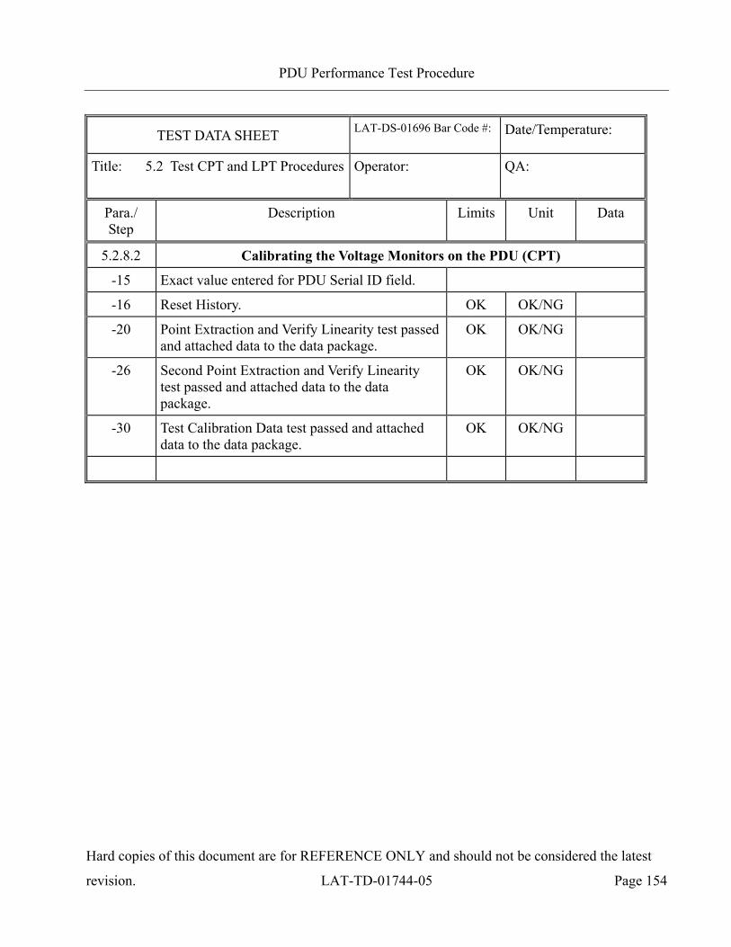
PDU Performance Test Procedure
Hard copies of this document are for REFERENCE ONLY and should not be considered the latest
revision. LAT-TD-01744-05 Page 154
TEST DATA SHEET LAT-DS-01696 Bar Code #:
Date/Temperature:
Title: 5.2 Test CPT and LPT Procedures Operator:
QA:
Para./ Step
Description Limits Unit Data
5.2.8.2 Calibrating the Voltage Monitors on the PDU (CPT)
-15 Exact value entered for PDU Serial ID field.
-16 Reset History. OK OK/NG
-20 Point Extraction and Verify Linearity test passed and attached data to the data package.
OK OK/NG
-26 Second Point Extraction and Verify Linearity test passed and attached data to the data package.
OK OK/NG
-30 Test Calibration Data test passed and attached data to the data package.
OK OK/NG
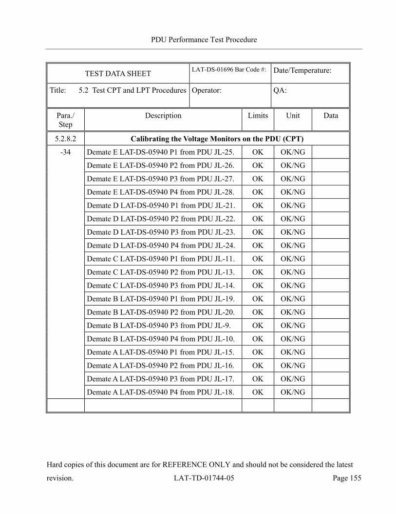
PDU Performance Test Procedure
Hard copies of this document are for REFERENCE ONLY and should not be considered the latest
revision. LAT-TD-01744-05 Page 155
TEST DATA SHEET LAT-DS-01696 Bar Code #:
Date/Temperature:
Title: 5.2 Test CPT and LPT Procedures Operator:
QA:
Para./ Step
Description Limits Unit Data
5.2.8.2 Calibrating the Voltage Monitors on the PDU (CPT)
-34 Demate E LAT-DS-05940 P1 from PDU JL-25. OK OK/NG
Demate E LAT-DS-05940 P2 from PDU JL-26. OK OK/NG
Demate E LAT-DS-05940 P3 from PDU JL-27. OK OK/NG
Demate E LAT-DS-05940 P4 from PDU JL-28. OK OK/NG
Demate D LAT-DS-05940 P1 from PDU JL-21. OK OK/NG
Demate D LAT-DS-05940 P2 from PDU JL-22. OK OK/NG
Demate D LAT-DS-05940 P3 from PDU JL-23. OK OK/NG
Demate D LAT-DS-05940 P4 from PDU JL-24. OK OK/NG
Demate C LAT-DS-05940 P1 from PDU JL-11. OK OK/NG
Demate C LAT-DS-05940 P2 from PDU JL-13. OK OK/NG
Demate C LAT-DS-05940 P3 from PDU JL-14. OK OK/NG
Demate B LAT-DS-05940 P1 from PDU JL-19. OK OK/NG
Demate B LAT-DS-05940 P2 from PDU JL-20. OK OK/NG
Demate B LAT-DS-05940 P3 from PDU JL-9. OK OK/NG
Demate B LAT-DS-05940 P4 from PDU JL-10. OK OK/NG
Demate A LAT-DS-05940 P1 from PDU JL-15. OK OK/NG
Demate A LAT-DS-05940 P2 from PDU JL-16. OK OK/NG
Demate A LAT-DS-05940 P3 from PDU JL-17. OK OK/NG
Demate A LAT-DS-05940 P4 from PDU JL-18. OK OK/NG
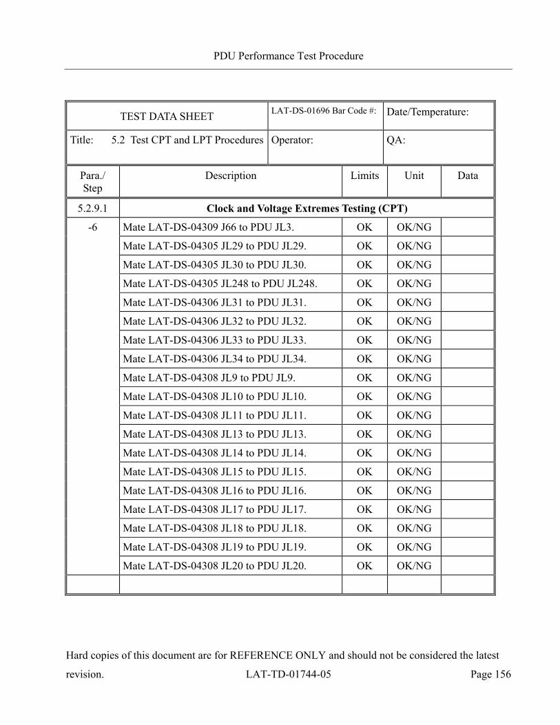
PDU Performance Test Procedure
Hard copies of this document are for REFERENCE ONLY and should not be considered the latest
revision. LAT-TD-01744-05 Page 156
TEST DATA SHEET LAT-DS-01696 Bar Code #:
Date/Temperature:
Title: 5.2 Test CPT and LPT Procedures Operator:
QA:
Para./ Step
Description Limits Unit Data
5.2.9.1 Clock and Voltage Extremes Testing (CPT)
-6 Mate LAT-DS-04309 J66 to PDU JL3. OK OK/NG
Mate LAT-DS-04305 JL29 to PDU JL29. OK OK/NG
Mate LAT-DS-04305 JL30 to PDU JL30. OK OK/NG
Mate LAT-DS-04305 JL248 to PDU JL248. OK OK/NG
Mate LAT-DS-04306 JL31 to PDU JL31. OK OK/NG
Mate LAT-DS-04306 JL32 to PDU JL32. OK OK/NG
Mate LAT-DS-04306 JL33 to PDU JL33. OK OK/NG
Mate LAT-DS-04306 JL34 to PDU JL34. OK OK/NG
Mate LAT-DS-04308 JL9 to PDU JL9. OK OK/NG
Mate LAT-DS-04308 JL10 to PDU JL10. OK OK/NG
Mate LAT-DS-04308 JL11 to PDU JL11. OK OK/NG
Mate LAT-DS-04308 JL13 to PDU JL13. OK OK/NG
Mate LAT-DS-04308 JL14 to PDU JL14. OK OK/NG
Mate LAT-DS-04308 JL15 to PDU JL15. OK OK/NG
Mate LAT-DS-04308 JL16 to PDU JL16. OK OK/NG
Mate LAT-DS-04308 JL17 to PDU JL17. OK OK/NG
Mate LAT-DS-04308 JL18 to PDU JL18. OK OK/NG
Mate LAT-DS-04308 JL19 to PDU JL19. OK OK/NG
Mate LAT-DS-04308 JL20 to PDU JL20. OK OK/NG
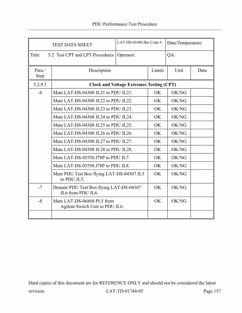
PDU Performance Test Procedure
Hard copies of this document are for REFERENCE ONLY and should not be considered the latest
revision. LAT-TD-01744-05 Page 157
TEST DATA SHEET LAT-DS-01696 Bar Code #:
Date/Temperature:
Title: 5.2 Test CPT and LPT Procedures Operator:
QA:
Para./ Step
Description Limits Unit Data
5.2.9.1 Clock and Voltage Extremes Testing (CPT)
-6 Mate LAT-DS-04308 JL21 to PDU JL21. OK OK/NG
Mate LAT-DS-04308 JL22 to PDU JL22. OK OK/NG
Mate LAT-DS-04308 JL23 to PDU JL23. OK OK/NG
Mate LAT-DS-04308 JL24 to PDU JL24. OK OK/NG
Mate LAT-DS-04308 JL25 to PDU JL25. OK OK/NG
Mate LAT-DS-04308 JL26 to PDU JL26. OK OK/NG
Mate LAT-DS-04308 JL27 to PDU JL27. OK OK/NG
Mate LAT-DS-04308 JL28 to PDU JL28. OK OK/NG
Mate LAT-DS-05550 J78P to PDU JL7. OK OK/NG
Mate LAT-DS-05550 J78P to PDU JL8. OK OK/NG
Mate PDU Test Box flying LAT-DS-04307 JL5 to PDU JL5.
OK OK/NG
-7 Demate PDU Test Box flying LAT-DS-04307 JL6 from PDU JL6.
OK OK/NG
-8 Mate LAT-DS-06868 PL5 from Agilent Switch Unit to PDU JL6.
OK OK/NG
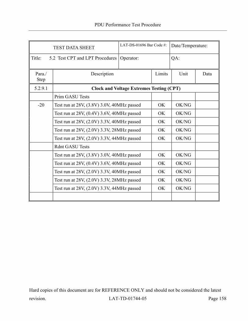
PDU Performance Test Procedure
Hard copies of this document are for REFERENCE ONLY and should not be considered the latest
revision. LAT-TD-01744-05 Page 158
TEST DATA SHEET LAT-DS-01696 Bar Code #:
Date/Temperature:
Title: 5.2 Test CPT and LPT Procedures Operator:
QA:
Para./ Step
Description Limits Unit Data
5.2.9.1 Clock and Voltage Extremes Testing (CPT)
Prim GASU Tests
-20 Test run at 28V, (3.8V) 3.0V, 40MHz passed OK OK/NG
Test run at 28V, (0.4V) 3.6V, 40MHz passed OK OK/NG
Test run at 28V, (2.0V) 3.3V, 40MHz passed OK OK/NG
Test run at 28V, (2.0V) 3.3V, 28MHz passed OK OK/NG
Test run at 28V, (2.0V) 3.3V, 44MHz passed OK OK/NG
Rdnt GASU Tests
Test run at 28V, (3.8V) 3.0V, 40MHz passed OK OK/NG
Test run at 28V, (0.4V) 3.6V, 40MHz passed OK OK/NG
Test run at 28V, (2.0V) 3.3V, 40MHz passed OK OK/NG
Test run at 28V, (2.0V) 3.3V, 28MHz passed OK OK/NG
Test run at 28V, (2.0V) 3.3V, 44MHz passed OK OK/NG
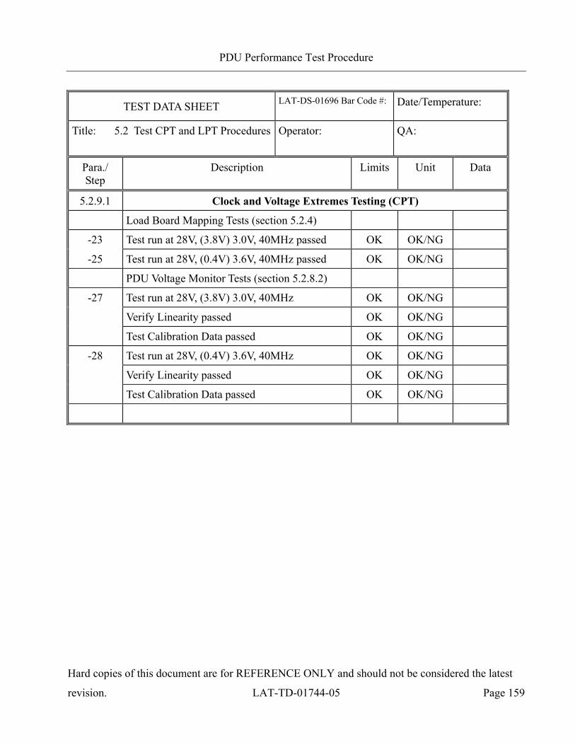
PDU Performance Test Procedure
Hard copies of this document are for REFERENCE ONLY and should not be considered the latest
revision. LAT-TD-01744-05 Page 159
TEST DATA SHEET LAT-DS-01696 Bar Code #:
Date/Temperature:
Title: 5.2 Test CPT and LPT Procedures Operator:
QA:
Para./ Step
Description Limits Unit Data
5.2.9.1 Clock and Voltage Extremes Testing (CPT)
Load Board Mapping Tests (section 5.2.4)
-23 Test run at 28V, (3.8V) 3.0V, 40MHz passed OK OK/NG
-25 Test run at 28V, (0.4V) 3.6V, 40MHz passed OK OK/NG
PDU Voltage Monitor Tests (section 5.2.8.2)
-27 Test run at 28V, (3.8V) 3.0V, 40MHz OK OK/NG
Verify Linearity passed OK OK/NG
Test Calibration Data passed OK OK/NG
-28 Test run at 28V, (0.4V) 3.6V, 40MHz OK OK/NG
Verify Linearity passed OK OK/NG
Test Calibration Data passed OK OK/NG
PDU Performance Test Procedure
Hard copies of this document are for REFERENCE ONLY and should not be considered the latest
revision. LAT-TD-01744-05 Page 160
Appendix B (Connector Mate/Demate Log)
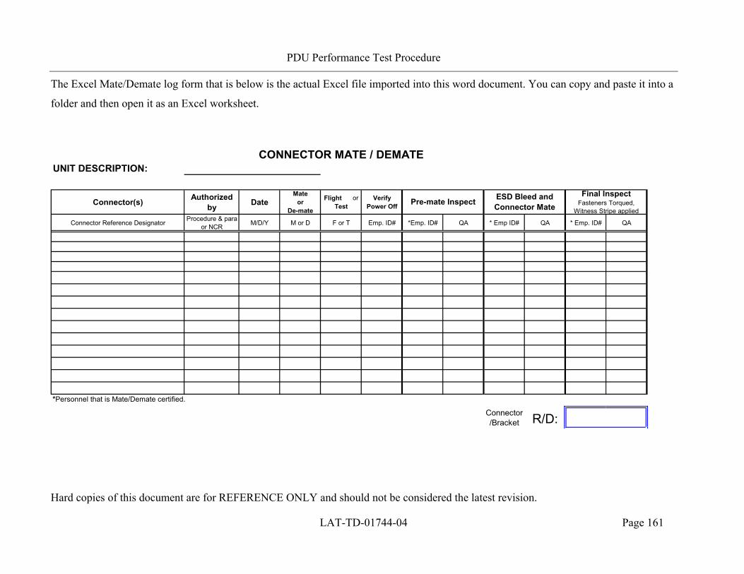
PDU Performance Test Procedure
Hard copies of this document are for REFERENCE ONLY and should not be considered the latest revision.
LAT-TD-01744-04 Page 161
The Excel Mate/Demate log form that is below is the actual Excel file imported into this word document. You can copy and paste it into a
folder and then open it as an Excel worksheet.
CONNECTOR MATE / DEMATEUNIT DESCRIPTION:
Connector(s) Authorized by Date
Mate or
De-mate
Flight or Test
Verify Power Off
Connector Reference Designator Procedure & para or NCR M/D/Y M or D F or T Emp. ID# *Emp. ID# QA * Emp ID# QA * Emp. ID# QA
*Personnel that is Mate/Demate certified.
Connector/Bracket R/D:
Pre-mate Inspect ESD Bleed and Connector Mate
Final Inspect Fasteners Torqued,
Witness Stripe applied