Nomadic Surveillance Camera - ULisboa · camera, onboard microcontroller); (iii) design a homing...
10
Nomadic Surveillance Camera Nuno Ribeiro, Ricardo Ferreira, Jos´ e Gaspar Instituto Superior T´ ecnico / UTL, Lisbon, Portugal [email protected], [email protected], [email protected] ABSTRACT Personal, inexpensive, easy-to-use, teleoperated, autonomous, mobile robots are starting to be a real- ity and are expected to be widespread within some few years. We present a proper methodology to control the robot over a network and make it return to its initial position. In this thesis we detail the base components forming the robot in terms of hardware and software, show navigation experiments based in Monocular SLAM, and propose a methodology to regulate the accumulated odometry error associated with map-less Monocular SLAM. We also present strategies for homing a robot to the point from where it started being teleoperated. Keywords: Teleoperation, MonoSLAM, Homing, Wireless IP Camera, Arduino, Car-like Robot. I. I NTRODUCTION Current personal robots are starting to have af- fordable prices. Those robots can be vacuum clean- ers such as the iRobot Roomba, can be telepresence robots, as the Anybots’ QA, or can be simply Mobile Webcams, such as the WowWee’s Rovio. Most of these robots have in common the combina- tion of mobile robotics, video cameras and wireless communications. In this work we propose using the wireless network of surveillance cameras as a basis to build networked mobile robots. We explore the possibility of having a teleoperated robot working indoors, allowing the user to check up its home even if he is far away. A. Related Work We calibrated our camera using Bouguet’s tool- box [1], in order to extract its intrinsic parameters, which are essential to determine 3D points projec- tion into the 2D image plane. To understand the kinematics involving our robot we resorted “Car Automatic Parking” [4], which presents the Kine- matic model for a car-like robot. From “Calibrating a Network of Cameras based on Visual Odometry” [7] we extracted information about decomposing a non-singular matrix using Gram-Schmidt, since we required a strategy to decompose a projection matrix in order to determine the camera localization. “Control an RC car from a computer over a wireless network” [3] presents software and documentation for teleoperation, and suggests homing as an im- portant topic for future work, without developing it on their project. We took advantage of some of their software, more precisely, the communica- tions software used to require a video feed from the camera and to send instructions that can be interpreted inside the camera. The article “1-Point RANSAC for EKF Filtering. Application to Real- Time Structure from Motion and Visual Odometry” [2] shows, conceptually, that is possible to have monocular vision, in our robot, in order to do visual odometry. The proposed algorithm also allows self- localization and robust mapping. B. Problem Formulation In this work we propose assembling a car-like robot using a IP wireless camera and onboard processing in order to have a setup, capable of being controlled over a network which can local- ize itself without any previous knowledge of the environment. This robot must be able to return to its initial position autonomously. The objectives of this work are threefold: (i) assemble one wireless camera and one microcontroller on a car; (ii) de- velop the required communication software between the different processing modules (PC, IP wireless
Transcript of Nomadic Surveillance Camera - ULisboa · camera, onboard microcontroller); (iii) design a homing...

Nomadic Surveillance Camera
Nuno Ribeiro, Ricardo Ferreira, Jose GasparInstituto Superior Tecnico / UTL, Lisbon, Portugal
[email protected], [email protected], [email protected]
ABSTRACT
Personal, inexpensive, easy-to-use, teleoperated,autonomous, mobile robots are starting to be a real-ity and are expected to be widespread within somefew years. We present a proper methodology tocontrol the robot over a network and make it returnto its initial position. In this thesis we detail the basecomponents forming the robot in terms of hardwareand software, show navigation experiments based inMonocular SLAM, and propose a methodology toregulate the accumulated odometry error associatedwith map-less Monocular SLAM. We also presentstrategies for homing a robot to the point fromwhere it started being teleoperated.
Keywords: Teleoperation, MonoSLAM, Homing,Wireless IP Camera, Arduino, Car-like Robot.
I. I NTRODUCTION
Current personal robots are starting to have af-fordable prices. Those robots can be vacuum clean-ers such as the iRobot Roomba, can be telepresencerobots, as the Anybots’ QA, or can be simplyMobile Webcams, such as the WowWee’s Rovio.Most of these robots have in common the combina-tion of mobile robotics, video cameras and wirelesscommunications. In this work we propose using thewireless network of surveillance cameras as a basisto build networked mobile robots. We explore thepossibility of having a teleoperated robot workingindoors, allowing the user to check up its home evenif he is far away.
A. Related Work
We calibrated our camera using Bouguet’s tool-box [1], in order to extract its intrinsic parameters,
which are essential to determine 3D points projec-tion into the 2D image plane. To understand thekinematics involving our robot we resorted “CarAutomatic Parking” [4], which presents the Kine-matic model for a car-like robot. From “Calibratinga Network of Cameras based on Visual Odometry”[7] we extracted information about decomposinga non-singular matrix using Gram-Schmidt, sincewe required a strategy to decompose a projectionmatrix in order to determine the camera localization.“Control an RC car from a computer over a wirelessnetwork” [3] presents software and documentationfor teleoperation, and suggests homing as an im-portant topic for future work, without developingit on their project. We took advantage of someof their software, more precisely, the communica-tions software used to require a video feed fromthe camera and to send instructions that can beinterpreted inside the camera. The article “1-PointRANSAC for EKF Filtering. Application to Real-Time Structure from Motion and Visual Odometry”[2] shows, conceptually, that is possible to havemonocular vision, in our robot, in order to do visualodometry. The proposed algorithm also allows self-localization and robust mapping.
B. Problem Formulation
In this work we propose assembling a car-likerobot using a IP wireless camera and onboardprocessing in order to have a setup, capable ofbeing controlled over a network which can local-ize itself without any previous knowledge of theenvironment. This robot must be able to return toits initial position autonomously. The objectives ofthis work are threefold: (i) assemble one wirelesscamera and one microcontroller on a car; (ii) de-velop the required communication software betweenthe different processing modules (PC, IP wireless

camera, onboard microcontroller); (iii) design ahoming strategy which enables the robot to returnautonomously to its initial position, using a Monoc-ular SLAM solution.
C. Thesis Structure
Section 1 introduces the objectives of this work,in particular, presents a short discussion on the stateof the art and our expectations with the project athand. In Section 2, we present our setup for ex-periments and describe the Hardware and Softwarecomponents involved. Section 3 presents the theorybehind our camera and the Kinematic model of thevehicle. Section 4 describes the possible strategiesfor homing and self-localization localization. Exper-imental results are shown and explained in Section5. Section 6 summarizes the work done and high-lights the main achievements and what we learnedwith this work. Moreover, this section proposesfurther work to extend and improve the strategiesand experiments described in this document.
II. H ARDWARE AND SOFTWARE SETUP
The first step of our work consists of creating areliable setup. The conceptual design of our systemis shown in fig.1.
Fig. 1. Conceptual design of our system.
A. Hardware components
To build the proposed setup, hardware was se-lected as much as possible of-the-shelf. All of thesecomponents have strict specifications which aredescribed in the design subsection. Every elementis important for the right behavior of the completesystem. The body and DC motors of the car are
from a commercial R/C car. The wireless IP cameraused is an Axis 207w, which is a camera built forthe surveillance market. The microcontroller is anArduino Uno. However, the Arduino can not outputsufficient current to power up the motors. One hasto use the Arduino Motor Shield mounted in theArduino Uno. The used hardware components areshown in fig.2.
(a) (b) (c)
(d) (e) (f)
Fig. 2. (a) Axis 207w camera. (b) 8× 1.2V AA battety pack.(c) Lithium batteries and USB box. (d) Arduino microcontroller. (e)Arduino Motor Shield. (f) Arduino and Motor Shield assembled
B. Design
One operational step consists in establishing theconnection between the camera mounted in the RCcar and the user’s computer and creating a wayto send commands from the client’s computer tothe car. We need a way to send commands fromthe camera to the microcontroller and a way tosend commands from the microcontroller to the carmotors. No less important, is getting a real timevideo feed from the camera to the user’s computer(to allow real time driving) and creating a friendlygraphical user interface for teleoperation. A morespecific design of our project at this stage is shownin fig.3.
1) Hardware: The hardware functionality is akey aspect of this project. The design of it is dividedby the following elements.
a) Wireless IP camera:The camera used inthis project is an Axis 207w. The processor withinthe camera allows executing a Linux OperatingSystem. The I/O terminal connector composes fourpins. Two pins are for power sourcing and the otherstwo are a digital input and a digital output. Thedigital output has a minimum output interval of 10ms. The camera has two main functions. The first

Fig. 3. Design of project at teleoperation stage.
is making available a video feed that can be sent toa user computer via wireless. Then, it is possible toopen and process each frame in the user’s computer.The second main function is to run a TCP/IP server,so a user can get connected and send commands tocontrol the car. This is possible, since the cameraruns a Linux OS, which allows us running a TCPserver and activating/deactivating the digital outputof the camera and that is the door from where wecan send signals to the microcontroler, for speed andsteering controls. The camera requires a constantvoltage within the range of 4.9V to 5.1V.
b) Arduino Microcontroller: In order to con-trol the motors, we need a programmable micro-controler, which controls the speed and direction ofrotation of each motor. We can control the speedof rotation with a Pulse Width Modulated (PWM)signal, supplied by the microcontroller. Besides, thecamera has a minimum output period of 10 ms,which is not adequate for supplying a PWM signal.Instead, the Arduino receives a message from the IPCamera and translates it into the appropriate signalsfor the steering and speed control. The frequencyof the used PWM signal is 32KHz. The PWMconfiguration also allows changing the signal dutycycle, which translates in middle voltage referencevalues for the motors. This way, one can speed upor turn the robot to levels between its maximum andminimum.
c) Arduino Motor Shield: Motor Shield letsus drive two DC motors with the Arduino board,controlling the speed and direction of each oneindependently. This shield has two separate channelsand each one uses 4 of the Arduino pins to drive or
sense the motor. Each channel supplies a maximumcurrent of 2A. In this way, we can control thedirection of each motor by setting HIGH or LOWthe direction pins. We can control the speed byvarying the PWM duty cycle values.
d) DC motors: The DC motors are controlledby the Arduino (microcontroller) plus Motor Shield.The current sent to the motors is a high frequencyPWM signal. In that way, we avoid forcing themotors to their maximum, which is extremely rel-evant when talking about the front (directional)motor, because this one should not saturate in themaximum turn angle. If that happens, i.e. the motorconstantly forcing the directional end of course,the car will not turn more and the motor can bedamaged.
e) Battery: The car can work, for some time,with a pack of 8× 1.2V (9.6V) AA batteries at1000mAh. With this power source, the camera ispowered up by the Arduino, which means that allpower required to feed the robot passes throughArduino. This leads to substantial heating of somesections of the Arduino board.
To improve reliability and time of operation ofour robot, we decided to use another power source.Using a box with 2 USB output ports, with fourPanasonic NCR18650B lithium-ion batteries inside(each one deploys a current of 2.5 A and has acapacity of 3400 mAh), it was possible to split theArduino, Motor Shield and motors power sourcefrom the camera power source. This way, the cam-era is no longer powered by the electric systemin Arduino, meaning the noise introduced by theArduino Motor Shield and motors no longer reachesthe camera. With this strategy, we can use our robotfor a number of hours without having to recharge.This strategy is shown in fig.4. A picture of ourrobot is in fig.5.
2) Comunications and Software:The hardwareset is the foundation of our work. Software isrequired to make more elaborated integration tasks.These involve data processing and communicationsprotocols, which will be explained in the next sec-tions. The architecture is centered on a server on thecamera which receives digital commands from theuser’s PC program and translate them into a signal,which is interpreted by the Arduino program. Theuser also requests a video feed for image processing,
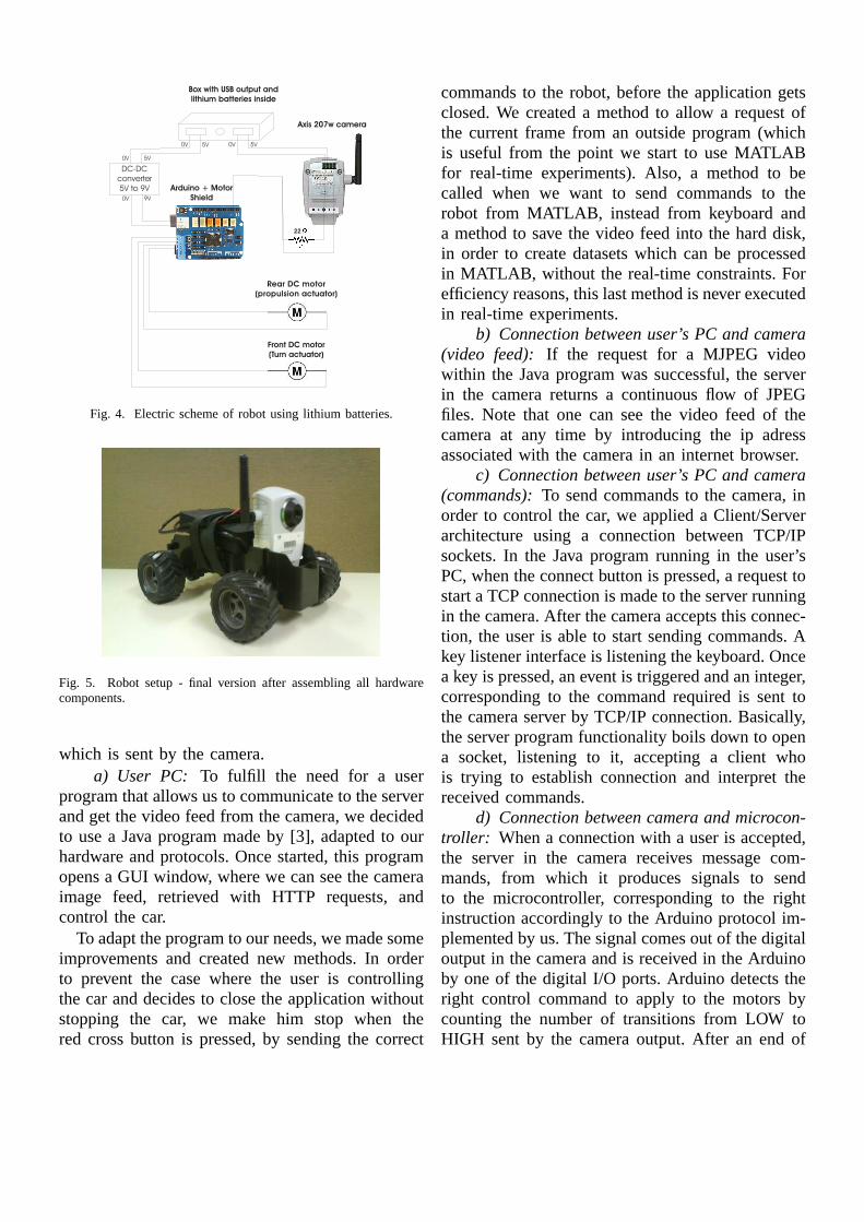
Fig. 4. Electric scheme of robot using lithium batteries.
Fig. 5. Robot setup - final version after assembling all hardwarecomponents.
which is sent by the camera.a) User PC: To fulfill the need for a user
program that allows us to communicate to the serverand get the video feed from the camera, we decidedto use a Java program made by [3], adapted to ourhardware and protocols. Once started, this programopens a GUI window, where we can see the cameraimage feed, retrieved with HTTP requests, andcontrol the car.
To adapt the program to our needs, we made someimprovements and created new methods. In orderto prevent the case where the user is controllingthe car and decides to close the application withoutstopping the car, we make him stop when thered cross button is pressed, by sending the correct
commands to the robot, before the application getsclosed. We created a method to allow a request ofthe current frame from an outside program (whichis useful from the point we start to use MATLABfor real-time experiments). Also, a method to becalled when we want to send commands to therobot from MATLAB, instead from keyboard anda method to save the video feed into the hard disk,in order to create datasets which can be processedin MATLAB, without the real-time constraints. Forefficiency reasons, this last method is never executedin real-time experiments.
b) Connection between user’s PC and camera(video feed): If the request for a MJPEG videowithin the Java program was successful, the serverin the camera returns a continuous flow of JPEGfiles. Note that one can see the video feed of thecamera at any time by introducing the ip adressassociated with the camera in an internet browser.
c) Connection between user’s PC and camera(commands):To send commands to the camera, inorder to control the car, we applied a Client/Serverarchitecture using a connection between TCP/IPsockets. In the Java program running in the user’sPC, when the connect button is pressed, a request tostart a TCP connection is made to the server runningin the camera. After the camera accepts this connec-tion, the user is able to start sending commands. Akey listener interface is listening the keyboard. Oncea key is pressed, an event is triggered and an integer,corresponding to the command required is sent tothe camera server by TCP/IP connection. Basically,the server program functionality boils down to opena socket, listening to it, accepting a client whois trying to establish connection and interpret thereceived commands.
d) Connection between camera and microcon-troller: When a connection with a user is accepted,the server in the camera receives message com-mands, from which it produces signals to sendto the microcontroller, corresponding to the rightinstruction accordingly to the Arduino protocol im-plemented by us. The signal comes out of the digitaloutput in the camera and is received in the Arduinoby one of the digital I/O ports. Arduino detects theright control command to apply to the motors bycounting the number of transitions from LOW toHIGH sent by the camera output. After an end of

Idle
1
2
4
3
crash
timeout
x=1
x=0
EOM
timeout
x=1 x=1
Parse Word
Fig. 6. Arduino program to receive one command, where x representsthe digital input value received from the camera. State 1 correspondsto wait-for-transition from HIGH to LOW. State 2 corresponds towait-for-transition from LOW to HIGH. State 3 occurs when acompleted command was received. State 4 is reached when a crashwas detected due to non-detected transition from HIGH to LOW,within a predefined period of time.
message timeout is achieved, the program preparesitself to receive a new instruction. If the cameracrashes and the digital output is HIGH, the Arduinoprogram will recognize the crash and will return tothe initial state. After Arduino receives a completeinstruction, it will update the signals which are con-stantly controlling the motors. The Arduino protocolestablished in its program is shown in fig.6.
III. C AMERA AND CAR MODELING
In this section we detail how 3D points in ageneric reference frame translate into 2D points inan image plane and how the camera parameterscan be estimated. We also describe the continuouskinematic model of the car and its discrete version,necessary to be processed in a computer.
A. Camera Calibration
In order to determine the pixel corresponding toa 3D point, one needs to determine the extrinsicand intrinsic parameters of the camera. The extrinsic
parameters are composed by a rotation matrix anda translation vector, which allow changing fromthe object reference frame to the camera referenceframe. In the case of non-varying optics, the intrin-sic parameters are fixed, and to determine them onecan use Bouguet’s calibration toolbox [1].
In our case we want to determine both the intrin-sic and extrinsic parameters. In other words we wantto estimate the camera projection matrix P. In orderto do that, we need to know the 2D coordinates(m) of feature points and their corresponding 3Dcoordinates (M). From [6], we can write
λm = PM (1)
where
M =
X
Y
Z
1
(2)
andλ is a scale factor that equals depth in 3D(λ =Z). So, from eq.1 we have
λ
u
v
1
=
P1:M
P2:M
P3:M
. (3)
From here we can observeλ = P3:M . Knowingthis, we can easily write
{
P1:M − uP3:M = 0P2:M − vP3:M = 0
(4)
Putting eq.4 in matrix form, gets
[
MT1
→
0
→
0MT
1
−u1MT1
−v1MT1
]
P T1:
P T2:
P T3:
=
[
00
]
(5)and for N points:
MT1
→
0 −u1MT1
→
0 MT1 −v1M
T1
MT2
→
0 −u2MT2
→
0 MT2 −v2M
T2
... ... ...
MTn
→
0 −unMTn
→
0 MTn −vnM
Tn
P T1:
P T2:
P T3:
=
00...
0
.
(6)

Fig. 7. Parameters to describe the car’s model and motion.
We call the first matrixA and the second oneπ. We want minimize the norm of the residualr = Mπ. To solve this,π must be the normalizedeigenvector associated to the smallest eigenvalue ofATA. To compute the required eignvalue, one canuse SVD decomposition[U, S, V ] = svd(A) whereS is a diagonal matrix of the same dimension asA,with non-negative diagonal elements,U andV areunitary matrices, so thatA = U ∗S ∗V T . In fact, Vcontains the ordered eigenvectors corresponding tothe ordered eigenvalues in S. The projection matrixelements we are looking for are in the eigenvectorcorresponding to the lowest eigenvalue. Then wemust order them as a matrix3× 4.
B. Kinematic model
The vehicle we use in this project has rear wheeldrive and is able to change direction by turningits front wheels. The points that can be reachedby the vehicle are path dependent. One needs fora nonholonomic kinematic model to describe thesystem and predict motion.
C. Continuous model
Using the kinematic model presented at [4], wecan write the kinematic equations related to thecentral point of the front axis as:
xf = v cos(θ + φ)yf = v sin(θ + φ)
θ = vsin(φ)
L
. (7)
wherev is the linear velocity inputted to the car.
D. Discrete model
In order to simulate the kinematic model ona computer, we have to translate its equations todiscrete time. To achieve that, we make first orderderivative using Leapfrog integration [10], whichgives us a good approximation.Considering N to be the timestep and n to be theactual discrete time instant, for the velocities, weget:
θ [n] = v[n] sin(φ[n])L
xf [n] = v [n] cos(
θ [n] + φ [n] + N2θ [n]
)
yf [n] = v [n] sin(
θ [n] + φ [n] + N2θ [n]
)
(8)
for the positions, we get
θ[n] = θ[n− 1] +Nθ[n]xf [n] = xf [n− 1] +Nxf [n]yf [n] = yf [n− 1] +Nyf [n]
(9)
IV. NAVIGATION AND CONTROL
We present in this section some strategies in orderto execute the homing procedure.
A. MonoSLAM
In order to use the camera as a sensor fromwhere we can extrapolate data to compute the poseof the vehicle, we decided to use the MonoSLAM[2]. By using MonoSLAM we obtain the vehicleposition and orientation in a 3D general frame andthe location of important features from where therobot knows where it is located. The MonoSLAMexplained in [2] is an algorithm, which consists inan Extended Kalman Filter (EKF) with a specialRandom Sample Consensus (RANSAC) embedded.Initially, the algorithm assumes that an a prioriprobability distribution over the model parametersis known which allows reducing the computationalcost in calculating the model. The EKF makes apose prediction of the vehicle. The update stepis made by using the most voted hypothesis inRANSAC which generates hypothesis from candi-date features matches. To detect local features in theimages a corner extraction procedure is used.
The state vectorW xk is composed by a set ofcamera parametersW xCk
and map parametersW yCk.
All these parameters are referred to a static frame
W ∧
x k =
(
W ∧
x Ck
W∧
y Ck
)
. (10)
The estimated mapWy is composed ofn pointfeaturesWyi andWy =
(
yWT1 ... yWT
n
)T. In
our case, we use MonoSLAM as a visual odometerand we are interested in getting the localization ofthe camera and the 3D features information. We getthis by accessing the Extended Kalman Filter statevectorW
∧
x k.
B. Autonomous Homing
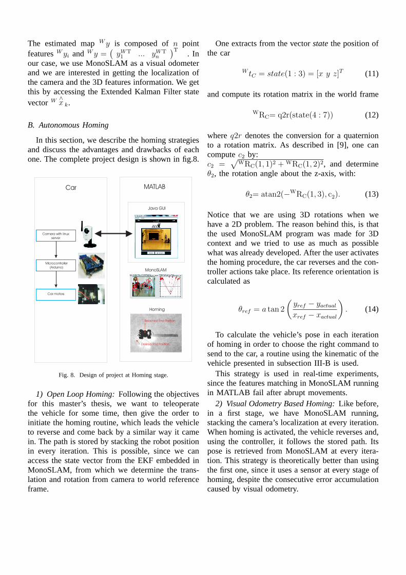
In this section, we describe the homing strategiesand discuss the advantages and drawbacks of eachone. The complete project design is shown in fig.8.
Fig. 8. Design of project at Homing stage.
1) Open Loop Homing:Following the objectivesfor this master’s thesis, we want to teleoperatethe vehicle for some time, then give the order toinitiate the homing routine, which leads the vehicleto reverse and come back by a similar way it camein. The path is stored by stacking the robot positionin every iteration. This is possible, since we canaccess the state vector from the EKF embedded inMonoSLAM, from which we determine the trans-lation and rotation from camera to world referenceframe.
One extracts from the vectorstatethe position ofthe car
W tC = state(1 : 3) = [x y z]T (11)
and compute its rotation matrix in the world frame
WRC= q2r(state(4 : 7)) (12)
whereq2r denotes the conversion for a quaternionto a rotation matrix. As described in [9], one cancomputec2 by:c2 =
√
WRC(1, 1)2 + WRC(1, 2)2, and determineθ2, the rotation angle about the z-axis, with:
θ2= atan2(−WRC(1, 3), c2). (13)
Notice that we are using 3D rotations when wehave a 2D problem. The reason behind this, is thatthe used MonoSLAM program was made for 3Dcontext and we tried to use as much as possiblewhat was already developed. After the user activatesthe homing procedure, the car reverses and the con-troller actions take place. Its reference orientation iscalculated as
θref = a tan 2
(
yref − yactual
xref − xactual
)
. (14)
To calculate the vehicle’s pose in each iterationof homing in order to choose the right command tosend to the car, a routine using the kinematic of thevehicle presented in subsection III-B is used.
This strategy is used in real-time experiments,since the features matching in MonoSLAM runningin MATLAB fail after abrupt movements.
2) Visual Odometry Based Homing:Like before,in a first stage, we have MonoSLAM running,stacking the camera’s localization at every iteration.When homing is activated, the vehicle reverses and,using the controller, it follows the stored path. Itspose is retrieved from MonoSLAM at every itera-tion. This strategy is theoretically better than usingthe first one, since it uses a sensor at every stage ofhoming, despite the consecutive error accumulationcaused by visual odometry.

3) Map Based Homing:With this strategy, wealso store the 3D features coordinates when thevehicle is being teleoperated, building that way amap. In the homing procedure, we compute theactual vehicle’s pose, by finding the camera matrixP and decompose it to the formK[CRW |CtW ].We can computeP becausem = PM , whereM are the features 3D points stored before andm are the 2D projection points from the cameraimage, corresponding to the 3D features. In orderto determine the vehicle’s pose fromP , we start byapplying QR factorization to P, than transform fromthe QR to the RQ factorization and then, correctthe sign of K. From this we obtain the matricesK,CRW andCtW . Knowing that
WRC = CRTW (15)
andW tC = −WRC .
CtW (16)
We extract the position fromW tC and the orientationangle fromWRC .To use this strategy, at least six features have tobe detected in each iteration (see eq.6), since wehave six unknown parameters. The great advantagein using this strategy, compared to the ones above,is that it allows resetting the visual odometry error,during the homing procedure. Since MonoSLAMuses EKF, exists always a probability of the filterlooses its consistency, specially with abrupt rota-tions, meaning that estimated state and its predictedmargin of error diverges from measurements. Find-ing known locations due to our feature map opensthe possibility to reset the error in EKF prediction.A simulation using this strategy is shown in fig.14.
V. EXPERIMENTS
This section describes the experiments performedto validate the methodologies introduced in previoussections.
A. MonoSLAM, self-localization error in a straightline path
After being able to run the MonoSLAM in realtime, we wanted to have an idea of the pose er-rors. Since the MonoSLAM is very sensitive to thechanges in direction, we tested it while the car wasmoving along a straight line.
Fig. 9. Straight line experiment.
(a) (b)
(c) (d)
Fig. 10. (a) First image of MonoSLAM running in the straight lineexperiment. (b) MonoSLAM catching a feature on the white pen. (c)Feature on white pen getting closer as the camera moves on. (d) Lastimage of MonoSLAM running in the straight line experiment.
MonoSLAM shows that the car is moving straight(fig.10(d)).The final orientation is similar to the realone. When a considerable number of features movesits position on the image plane from one frame tothe next, the algorithm understands the movementand realizes if the camera is sliding right, left,up, down, or if it is actually moving forward orbackward. After measuring the car position every50 cm with a ruler and comparing to the positiongiven by the MonoSLAM, we plotted the results(fig.11) to have an idea of the scale factor betweenthe MonoSLAM direct measurements and the ruler.After computing a linear regression of used data
points, we got the line slope. By dividing theMonoSLAM measurements with the slope value, wegot the measurements in the same metric scale asthe ruler measurements. After plotting the scaledMonoSLAM measurements versus ruler measure-ments and drawing a line corresponding to the idealcase, we found how close are the MonoSLAM

Fig. 11. Ruler vs MonoSLAM measurement to get scale factor.
Fig. 12. Ruler vs MonoSLAM measurement in same metric scale.
measurements to the ideal case (fig.12).
B. Open Loop Homing experiment
In this experiment, we moved the robot for sometime along a straight line (worst case scenario), thenthe homing procedure was triggered (fig.13(b)) andthe robot returned to its initial position (fig.13(c)and (d)).
The difference between the MonoSLAMestimated positions and the real ones is shown intable I. The results are considerably different. Thefinal vehicle’s pose is shown in fig.13(d). From theexperiments made, we conclude that MonoSLAM
real estimatedX (cm) 22 5Y (cm) -16 -8θ (o) -55 -41
TABLE IREAL AND MONOSLAM MEASUREMENTS COMPARISON.
(a) (b)
(c) (d)
Fig. 13. (a) Start of experiment. (b) Start of homing procedure. (c)After reversing, the car goes to its initial position. (d) End positionand orientation measurement.
easily detects changes in direction of motion, butits not very accurate at determining the magnitudeof the forward motion of the camera, especially ifthere is no significant movement in more directions.The high computational cost of runningMonoSLAM in MATLAB makes the job athand difficult. No abrupt movements can be doneor otherwise the difference between two consecutiveimages will lead to no features matches.
Using the kinematic model as the only predictionof pose while homing is possible, but leads also toa rapid increase of the pose prediction errors.
C. Map Based Homing simulation
This experiment was made to test the Map BasedHoming strategy in simulation. A wide numberof 3D features were spread according to normaldistribution with 0 mean and unitary variance. A setof commands was sent to the simulated robot whichended up by doing a trajectory. In the meantime, thecar was saving its consecutive positions in order tostore a path, and a map of 3D features was beingbuild by storing the 3D features that were in the fieldof view of the camera (red points in fig.14). Whenthe robot stops receiving commands, the homingprocedure is triggered and the controller takes thecar back trough the inverted stored path (fig.14(b)and (c)). When the robot gets close enough to acheckpoint of the path, the reference destination

(a) (b)
(c) (d)
Fig. 14. (a) Beginning of Map Based Homing simulation. (b)Beginning of homing procedure. (c) Homing procedure at middle.(d) Final car pose.
becomes the next checkpoint, until the car reachesits destination. If the car can not reach a pointdue to restrictions in the degrees of freedom, itmakes a reverse maneuver in order to get closerto the desired checkpoint. The position of the robotduring this procedure is computed by decomposingthe camera matrix in translation and rotation. Thiscamera matrix is computed at every iteration usingeq.6, where the 2D points(u, v) correspond to the2D coordinates of the 3D features in the imageplane, captured by the field of view of the camera.
VI. CONCLUSION AND FUTURE WORK
This work started with the integration of the vari-ous hardware components into a mobile robot. Var-ious positive conclusions can be extracted. The firstconclusion is that wireless IP cameras are practicaland functional tools to help building teleoperatedrobots. Also, we can say that is already possible tobuild a teleoperated vehicle with autonomous fea-tures at a reasonable cost. MonoSLAM was tested ina variety of experiments and, we conclude that it ispossible and plausible to acquire odometry measure-ments using MonoSLAM but, as expected, we haveconsiderable error accumulation. One possible waythat is being considered to future use, is to decreasethis error accumulation by resetting it, by comparingthe actual image with the ones stored in an imagesmap, as was proposed in Vision Based-navigation
and Environmental Representations with an Omni-directional Camera [5]. An alternative way is mod-ifying the scenario either by adding landmarks orfixed cameras informing the car location.
Changing the features detector mechanism ofMonoSLAM from corner extraction to a better one,like SIFT would improve the quality of detectedfeatures and make localization more reliable. Thisis an important step in order to make a Map BasedHoming experiment with our setup, since this allowshaving more and better features. The Map BasedHoming strategy is also important to reset the errorassociated with our EKF prediction, in case it lostits convergence.
PUBLICATIONS AND ACKNOWLEDGMENTS
The work described in this thesis has been par-tially published in RecPad 2013 [8]. This work hasbeen partially supported by the FCT project PEst-OE / EEI / LA0009 / 2013, by the FCT projectPTDC / EEACRO / 105413 / 2008 DCCAL, andby the FCT project EXPL / EEI-AUT / 1560 / 2013ACDC.
REFERENCES
[1] Jean-Yves Bouguet. Camera calibration toolbox for matlab.http://www.vision.caltech.edu/bouguetj.
[2] J. Civera, O. Grasa, A. Davison, and J. Montiel. 1-point ransacfor ekf filtering. application to real-time structure from motionand visual odometry.J. Field Robot., 27(5):609–631, 2010.
[3] James Crosetto, Jeremy Ellison, and Seth Schwiethale. Controlan rc car from a computer over a wireless network. https://code.google.com/p/networkrccar.
[4] Mario Filipe Florencio and Pedro Emanuel Agostinho.Par-queamento Automovel Automatico. Instituto Superior Tecnico,2005.
[5] J. Gaspar, N. Winters, and J. Santos-Victor. Vision based-navigation and environmental representations with an omni-directional camera.IEEE Transactions on Robotics and Au-tomation, 16:890–898, 2000.
[6] R. Hartley and A. Zisserman. Multiple View Geometry inComputer Vision. Cambridge University Press, 2004.
[7] N. Leite, A. Del Bue, and J. Gaspar. Calibrating a network ofcameras based on visual odometry. InProc. of IV Jornadasde Engenharia Electronica e Telecomunica coes e de Computa-dores, Portugal, pages pp174–179, 2008.
[8] Ricardo Ferreira Nuno Ribeiro, Jose Gaspar. Homing a teleop-erated car using monocular slam.RecPad, 2013.
[9] Bruno Siciliano, Lorenzo Sciavicco, Luigi Villani, andGiuseppe Oriolo.Robotics: Modelling, Planning and Control.Springer, 2008.
[10] Peter Young. The leapfrog method and other symplecticalgorithms for integrating newton laws of motion. http://young.physics.ucsc.edu/115/leapfrog.pdf, 2013.