Noel Burton - ASPECT 2012 - Resignalling Auckland - NJB ... Burton - Resignalling... ·...
16
Resignalling Auckland Page 1 of 16 RESIGNALLING AUCKLAND Noel Burton, B.Sc. (Hons.), MIRSE, Invensys Rail SUMMARY This paper provides a technical description of the new signalling system deployed in Auckland to replace life- expired assets and prepare the railway for an electrified future. The Auckland Metropolitan Resignalling Project (AMRP) is a true “turn key” signalling project with all of the signalling infrastructure being renewed and the addition of Automatic Train Protection (ATP), both trackside and onboard. The paper provides in-depth technical descriptions of how the project has deployed some of the key signalling sub systems such as 750 axle counters sections, WESTRACE MkII, ETCS Level 1 and an innovative new modular location system for deploying them all in a quick and cost effective manner. Key engineering challenges and how they were overcome are also discussed. For any signalling engineer, the AMRP provides an insight into what can be achieved with a clean sheet of paper and a remit from the customer to innovate and improve. 1 INTRODUCTION Auckland is located in the north island of New Zealand, has a population of around 1.5 million people and accounts for over 35% of the nation’s Gross Domestic Product. A severe lack of investment in the railways in the 1990’s resulted in trains becoming a “last resort” in terms of public transport for the city. In fact, the railway was considered such an irrelevance that the local authorities didn’t even bother to run a service on weekends. Fast forward ten years and a program of continued investment in the railways and high petrol prices has now resulted in such high patronage growth that there is overcrowding even with 15 minutes frequencies during the peak. This change in fortunes started when the main city terminus was relocated to a position far more convenient for city commuters. Significant further growth was encouraged with project DART (Developing Auckland’s Rail Transport) which saw the rebuilding of some key stations and double tracking of the Western Line and was largely completed in 2010. The Auckland Electrification Project (AEP), which started in 2009, is responsible for the complete electrification of the network using the 25kV AC electrification system and aims to continue the good work done by project DART in further increasing the capacity and usability of the rail network. The AEP is funded by the New Zealand government and managed by KiwiRail (KR), the infrastructure provider in New Zealand. AEP will also see the complete replacement of the very old fleet of Diesel Multiple Units (DMUs) and loco hauled trains, with brand new Electrical Multiple Units (EMUs) to offer a much faster service with a 10 minute service frequency and longer trains on all lines. The majority of signalling assets in Auckland were life expired, some dating from the 1920’s and none were immunised for use with AC traction. KR commissioned a detailed study which came to the conclusion that a full resignalling would provide by far the best value, by avoiding the complexities of modifying existing installations and providing a reliable system tailored to the busy mixed traffic metropolitan railway that Auckland now is. Not many railway signalling projects can claim to be more “turn key” than the AMRP. The scope for Invensys Rail (IR) includes; collaborative development of new “suburban” signalling principles, design, provision, installation and T&C of new signals, point machines, axle counters, location cases, centralised interlockings, control centre, communications network, power system and European Train Control System (ETCS) Level 1 both trackside and onboard. 2 PROJECT OVERVIEW 2.1 Network Overview and Staging Figure 1 shows the full extent of the passenger rail network in Auckland. The network is based on two main lines. One forms the main trunk line to the south, with the other serving the Western suburbs and eventually
Transcript of Noel Burton - ASPECT 2012 - Resignalling Auckland - NJB ... Burton - Resignalling... ·...

Resignalling Auckland Page 1 of 16
RESIGNALLING AUCKLAND
Noel Burton, B.Sc. (Hons.), MIRSE, Invensys Rail
SUMMARY
This paper provides a technical description of the new signalling system deployed in Auckland to replace life-expired assets and prepare the railway for an electrified future.
The Auckland Metropolitan Resignalling Project (AMRP) is a true “turn key” signalling project with all of the signalling infrastructure being renewed and the addition of Automatic Train Protection (ATP), both trackside and onboard.
The paper provides in-depth technical descriptions of how the project has deployed some of the key signalling sub systems such as 750 axle counters sections, WESTRACE MkII, ETCS Level 1 and an innovative new modular location system for deploying them all in a quick and cost effective manner. Key engineering challenges and how they were overcome are also discussed.
For any signalling engineer, the AMRP provides an insight into what can be achieved with a clean sheet of paper and a remit from the customer to innovate and improve.
1 INTRODUCTION
Auckland is located in the north island of New Zealand, has a population of around 1.5 million people and accounts for over 35% of the nation’s Gross Domestic Product. A severe lack of investment in the railways in the 1990’s resulted in trains becoming a “last resort” in terms of public transport for the city. In fact, the railway was considered such an irrelevance that the local authorities didn’t even bother to run a service on weekends. Fast forward ten years and a program of continued investment in the railways and high petrol prices has now resulted in such high patronage growth that there is overcrowding even with 15 minutes frequencies during the peak.
This change in fortunes started when the main city terminus was relocated to a position far more convenient for city commuters. Significant further growth was encouraged with project DART (Developing Auckland’s Rail Transport) which saw the rebuilding of some key stations and double tracking of the Western Line and was largely completed in 2010. The Auckland Electrification Project (AEP), which started in 2009, is responsible for the complete electrification of the network using the 25kV AC electrification system and aims to continue the good work done by project DART in further increasing the capacity and usability of the rail network. The AEP is funded by the New Zealand government and managed by KiwiRail (KR), the infrastructure provider in New Zealand. AEP will also see the complete replacement of the very old fleet of Diesel Multiple Units (DMUs) and loco hauled trains, with brand new Electrical Multiple Units (EMUs) to offer a much faster service with a 10 minute service frequency and longer trains on all lines.
The majority of signalling assets in Auckland were life expired, some dating from the 1920’s and none were immunised for use with AC traction. KR commissioned a detailed study which came to the conclusion that a full resignalling would provide by far the best value, by avoiding the complexities of modifying existing installations and providing a reliable system tailored to the busy mixed traffic metropolitan railway that Auckland now is.
Not many railway signalling projects can claim to be more “turn key” than the AMRP. The scope for Invensys Rail (IR) includes; collaborative development of new “suburban” signalling principles, design, provision, installation and T&C of new signals, point machines, axle counters, location cases, centralised interlockings, control centre, communications network, power system and European Train Control System (ETCS) Level 1 both trackside and onboard.
2 PROJECT OVERVIEW
2.1 Network Overview and Staging
Figure 1 shows the full extent of the passenger rail network in Auckland. The network is based on two main lines. One forms the main trunk line to the south, with the other serving the Western suburbs and eventually

Resignalling Auckland Page 2 of 16
becomes the main line to the North. The South line has a parallel loop which serves communities to the East of the city. Two branches serve Onehunga and the Manukau City shopping centre. All train services run into the main city centre terminus, Britomart.
All lines are double track except for the single track Onehunga branch which was restored for passenger use during the project.
When completed the signalling will comprise of 1048 Signalling Equivalent Units (SEU), where each point end, signal and level crossings is counted as an SEU.
SP 1
N
Phase 5A
Phase 5B
Phase 5C
Figure 1 - Overview of Auckland’s railways showing the topology of the 80km double track network.
Separable Portions SP1A, 1B, 2, 3, 4A, 4B & 5A were completed between November 2010 and January 2012. The final commissioning, combining SP5B and 5C, will occur in June 2012.
SP1A and 1B were the first priority for KR as these covered the area where Rugby World Cup shuttle trains would operate in September 2011. This added significant engineering pressure as many of the systems being deployed were new, with their first in service application on the busiest part of the system. This critical area was commissioned at the end of 2010. SP2, then SP4A, 4B & 5A and finally SP3 were commissioned during 2011.
2.2 Signalling Principles
A move to route setting style of interlocking, along with the mandatory overlap requirements associated with the provision of an ATP system, and other functional requirements such as bi-directional running, meant that the existing signalling principles were not compatible with the new signalling. At an early stage a number of workshops with KR’s signalling and operations representatives were held to determine an entirely new set of signalling principles. Few areas were off limits and most existing principles were questioned and assessed as to how they would work with the proposed system. Only principles that were essential for safe interoperability with the rest of KR’s 4000km network, such as signal aspects, were considered fixed for the benefit of the freight train loco engineers who have to traverse both areas regularly.
During this process there was an openness to accept good ideas from other railways where applicable rather than re-inventing principles from scratch. An example of this was the principles surrounding the application of axle counters. It was observed that the Australian Rail Track Corporation (ARTC) principles provided functionality very close to what was required. These were then used as a template and fine tuned for the New Zealand application.

Resignalling Auckland Page 3 of 16
2.3 Operational Flexibility and Tools
A key objective of the resignalling was to provide an improved system with more capacity and flexibility for operators, while simultaneously improving safety.
New signalling scheme plans were designed by IR and developed into detailed signalling arrangements, following consultation with the operators. All signal spacings were reviewed and signals were optimised for 4 aspect signalling (previously 3 aspect was provided throughout the network except in a few cases where freight train braking required 4). This provided between 16 and 24 t.p.h. headways, depending on the area of the network. The Advanced Caution aspects spaced for freight braking and the Caution aspects for the new EMUs.
Full bidirectional operation has been provided in the SP1b area, with all remaining double track sections fitted with SIMplified BI-Directional Signalling (SIMBIDS) with crossovers every 5-8km. This additional flexibility is in regular use, particularly during the night time electrification works, but has also proved invaluable to allow services to be continued around a failed train during the day.
Intermediate signals on plain line in NZ would typically be plated as ‘stop and proceed’ when at red. These signals are now plated as ‘stop and stay’. To mitigate this more restrictive configuration, all of these signals are fitted with subsidiary “A” lights which can be turned on by the train controller. When illuminated these turn the signal into a ‘stop and proceed’ signal from a rules perspective. The A lights are typically used for authorising a train into a section requiring an axle counter sweep or to join with a failed train ahead. The data in the lineside object controllers is configured to automatically turn the A lights on if communication is lost with the central interlocking for more than 60 seconds. This would reduce the workload on the train controllers should a major systems/communication failure.
The project has seen the provision of standard 150m overlaps for all main routes, whereas previously they were provided on a more ad hoc basis. Warner routes were introduced, where it is operationally beneficial to not lock the full overlap. As this was a new class of route, workshops were held to decide on the best way to indicate the restricted overlap to a driver. The solution agreed was to provide a Dynamic Speed Indicator (DSI) unit above the signal in rear which would display the allowable speed to approach the next signal. The speed displayed would typically be 20kph but could be higher if a longer, but not full, overlap was available. Inevitably DSIs soon found another application to improve junction signalling. The default medium speed for diverging junctions in NZ is 25kph, but this can be increased by signage if higher turnout speeds are permitted. In this case the signal in rear now displays a flashing DSI indication of the higher medium speed.
3 SYSTEM ARCHITECTURE
When tackling a project of this size, determining the correct system architecture is of utmost importance. For both interlocking and train control the project has utilised an architecture which has centralised “smarts” connected to many small distributed object controllers or terminals. This allows all of the most critical equipment to be co-located near to the maintenance depot for easy and fast access.
To remove single points of failure the interlockings have been configured in hot standby functionality with duplication of all components, including interlocking processor modules, power supplies, network switches and routers. However hot standby features cannot protect against the very small risk of a catastrophic failure to the whole equipment room, such as fire. This is mitigated by having a second Centralised Signalling Equipment Room (CSER) with duplicated equipment in a mix of hot and warm standby configurations, located in a geographically diverse location on the network.
The distributed architecture means that only fibre and power cables are required to run long distances along the trackside. This reduces the amount of cabling and simplifies engineering from an immunisation standpoint.
All subsystems on the network, both vital and non vital, communicate using Ethernet IP communications.

Resignalling Auckland Page 4 of 16
Figure 2 – A simplified and generic view of the system architecture deployed in Auckland for all the major subsystems, including the two geographically diverse Centralised Signalling Equipment Rooms (CSERs). The full system diagram is much larger as there are 144 modular location cases and a number of loops within the
communications network.
3.1 Communications
The railway between Quay Park, Westfield, Penrose and Newmarket forms a natural ring for a fibre backbone between all locations. Two more rings have been created by the provision of permanent 3rd party comms links between Swanson and Onehunga and another between Papakura and Newmarket. In this way each object

Resignalling Auckland Page 5 of 16
controller can communicate back to the interlocking by two completely diverse paths which are dual active to provide seamless continuation of service in the event of a switch or fibre cable failure.
3.1.1 A hard lesson learnt
The communications network started out as the very simple arrangement provided for the early resignalling of Newmarket over Christmas 2009. The network at this stage consisted of less than 10 network switches and one router. When the first two formal stages of the main contract were added (SP1a and SP1b) the same network architecture was expanded. This proved to perform adequately with some minor alterations. However with the addition of SP2, two large loops were added to the network and the original dynamic re-routing for failure scenarios started to seriously struggle. Although it worked, re-routings were not instantaneous and therefore not suitable for a real time system. It quickly became apparent it would not scale for the next stage of the project which would effectively double the number of network nodes and add another 2 large loops to the network topology.
After much analysis and lab testing, an updated network routing strategy was developed that avoided the use of dynamic routing and virtual gateways in favour of a fixed diversity model with all traffic being routed on two virtual diverse paths in duplicate. This enhanced solution performs excellently and provides seamless continuity of service even in the event of a failure.
Ethernet networks are widely used throughout the world and are relatively simple to set up for small systems. However the project highlighted that in depth engineering and planning is essential for their use in large real-time systems. This engineering is not necessarily straight forward. For example, the Auckland network has over 200 network switches, 30 routers and 500+ connections to various equipment, but there is no simulator available which can guarantee correct real-time failure mode emulation of all the networking equipment. This is caused by the subtle difference of networking equipment from differing suppliers, as well as the behaviours of proprietary interlockings, ETCS and train control equipment. This means the designed system cannot be fully validated until it is installed on site. This problem is carried forward to the later deployment phases when additional equipment is to be added or faults need to be addressed. Maintaining a full scale replica in a lab is not realistic as the space and cost implications are prohibitive. The only viable solution is to maintain a scaled down lab rig with a sample of each type of equipment and very thorough desk checking and rechecking. Therefore some on site testing of changes is always required. However, this is hard to achieve without putting the live network at risk, so significant changes can only be completed at night or block of line periods.
As Ethernet connectivity of signalling equipment becomes an industry standard for many suppliers, that the science of Ethernet Network Engineering will become more and more important for signalling project engineers to understand and respect. This does not mean that Ethernet networking need be complicated or feared but like all other aspects of signalling engineering, careful and methodical design based on proven concepts is essential.
3.2 Power Supplies
KR required the power supply sub system to be resilient to one cable break and/or a failure of mains power. Traditionally this would be satisfied by the provision of a generator and cross feeding from the adjacent power feed points. For Auckland, in addition to the cost of 15-20 generators, this would mean that the main trackside
Figure 3 – An engineer testing changes to the Ethernet network at night – if it doesn’t work enough time to restore the old configuration before the morning train service starts at 4am
must be allowed for, meaning actual engineering time is limited to 1-2 hours per night – hence, it is a very slow and
costly exercise to engineer on the live system.

Resignalling Auckland Page 6 of 16
power cable would have to be sized to supply not only its own area’s power but also that required for an adjacent area in times of failure. This would effectively double its size. Also, with route setting being introduced there were now some sites where a large number of point machines could be called simultaneously by a single route. This would either require unfeasibly large power cables or point sequencing logic which would affect headways.
The IR engineering team decided to turn this “typical” power arrangement on its head and instead provide a pseudo UPS in each location – all 144 of them! The “UPS” in each location is made up of a 48V 120Ah battery pack and charger. The distributed back-up arrangement has the following advantages:-
• The power reticulation system to locations is limited to a simple 400V single phase floating supply with just enough capacity to provide power to battery charger in each object controller location.
• The power reticulation system does not need to be specified to cover for adjacent sites in case of cable damage, as battery back up in locations allows 24 hours for cable repair.
• The battery pack in each location case can accommodate the inrush and standing load for up to 4 point machines. At Westfield Junction for example, some complex routes which span many location areas can potentially call 15 point machines to move simultaneously. This results in a combined inrush of around 150-300A @120Vdc and stable load of 90A. This kind of simultaneous movement of large number of machines would be very hard to accommodate using a traditional direct feeder arrangement.
• Guaranteed supply for axle counter and other electronic equipment in every location.
4 SIGNALLING EQUIPMENT
4.1 Interlockings
Invensys Rail offered the new WESTRACE MkII interlocking product for this project to provide substantial speed and capacity benefits. However it carried the risk associated with being a yet unproven product, as it was still in development at the time of contract award. KR agreed with IR that the benefits outweighed the risk, especially over the life span of the installation.
A trial site was established elsewhere in New Zealand in a 25kV electrified area to demonstrate to KR the reliability of the product, by May 2012 this 4 module installation had completed a staggering 108 million I/O changes of state. There are now over 1400 MkII modules installed in Auckland with a combined 6.5 million module hours of service time (May 2012).
As shown in figure 2 (see chapter 3) the interlocking architecture has centralised hot standby interlockings with remote distributed object controllers to interface to the signalling objects. There are 9 centralised interlockings, each communicating with between 15 and 40 object controllers in the field. Both the interlockings and object controllers use WESTRACE MkII and are made up of 4 main modules:
4.1.1 Processor Module (PM)
The PM is the programmable logic card of the system. Each interlocking has two PMs which run in a hot standby configuration for maximum availability. The Auckland network could have been controlled by a single PM. However, this would not have been practical for system commissioning or maintenance. Therefore, the system was divided into 9 relatively small interlocking areas to suit the commissioning staging plan. This strategy allowed all interlocking boundaries to be placed in ideal positions (i.e. on plain line sections) and also allowed work on the
Figure 4 - An object controller housing with hot standby PM modules. Each card is hot swappable and are totally enclosed, which has resulted in a lot less damaged cards at
commissioning compared with older equivalent open PCB card systems.

Resignalling Auckland Page 7 of 16
data design for various stages to progress in parallel. This was more advantageous than the cost saving of providing less hardware.
4.1.2 Parallel Input Module (PIM)
The PIM has twelve 50V DC voltage sensing inputs. On this project they are used for point detection, axle counter inputs (both track clear and track occupied are positively provided to the interlocking) and level crossing status indications.
4.1.3 Relay Output Module (ROM)
The ROM has eight isolated, double cut, 50V DC outputs. The ROMs are used to drive high current Q relay contactors for operating the points. They are also used to provide reset commands to the axle counters.
4.1.4 Lamp Output Module (LOM)
The LOM has six 110V AC current sensed double cut outputs. Each output can be configured to flash at a selectable rate. A useful feature is that the characteristics for lamp proving can be configured in data for each output. This is extremely useful as quite often there are different characteristics between different types of LED signal lamps. Over current protection is also provided that will detect if one output is driving more than its intended load (such as a wrong side failure caused by a crushed multicore cable) and shut down the output. An optional Red Retain feature is available that allows up to 2 outputs to be red retained in even of LOM failure. This avoids the need for any bespoke free wiring to achieve this functionality.
4.1.5 Notable data features
Every signal and point is provided with a block command for the train controller to bar its operation. At interlocking start-up all blocks are in their safe state, i.e. “block applied”. However, the disaster recovery interlockings in CSER-B do not share memory states with the live interlockings, so if control has to be switched to them all block memory would be lost. It was calculated that it would take up to an hour to remove all of the blocking and this also presented a risk of accidentally removing intentional blocking in the rush. To eliminate this problem each object controller has a latch in its data which confirms that there are no blocks for the signals and/or points controlled by that location currently applied. When an interlocking starts up it checks this latch in the object controller. If set high, it selects all the corresponding blocks for that location area as “block not applied”.
Another notable feature of the new interlocking and object controller data in Auckland is the provision of full aspect degradation functionality for all main signals. Signals automatically degrade to the next lower available aspect upon a lamp failure and the aspect sequence for signal(s) in rear is automatically updated.
4.2 Train Detection
Axle counters were assessed to be the best solution to provide both AC immunisation, allow simple dual rail traction return, there advertised reliability and remove the requirement for any possession time to complete the testing of train detection equipment.
A distributed solution using Frauscher ACS2000 axle counters has been deployed. Each of the 144 object controller locations has its own small set of 4-12 axle counter sections, with counting heads driven directly from the location. The Frauschers have proved to be extremely straight forward to commission with rail clamp mounted heads which auto calibrate and have performed equally well post commissioning with no equipment failures to date.
To provide extra system resilience in critical areas, such as the throat of the main terminus, duplicate heads have been provided on
Figure 6 – Axle Counter head showing rail foot clamp
arrangement which means it can be installed quickly with no rail
drilling and normally under lookout protection between trains.

Resignalling Auckland Page 8 of 16
crossovers. The tracks on the up and down line are therefore completely independent and not reliant on a common head, thereby limiting the operational impact of a single track section failure.
At road level crossings axle counters are not used to provide the island track section. Instead the island track function is provided by a short DC track circuit. This allows hi-rail vehicles to on/off track at level crossings without causing a miscount on the axle counter system. However a technical solution is yet to be found to prevent hi-rails swapping from up to down line mid section during night time possessions.
4.3 Signals
When complete Auckland signalling system will have 330 main controlled signals, 120 intermediate signals (automatics), 86 ground shunt signals and 7 banner repeater signals. All main signals are fitted with subsidiary “low speed” aspects which allow for permissive moves to all routes.
KR and IR jointly developed a new folding mast signal post design that would have two benefits in Auckland over the traditional fixed post and ladder arrangement. Primarily it removes the complication for the KR signal maintainers to have to meet current and future working at heights legislation. It also removes the need for costly overhead electrification protection cages for each signal structure.
A disconnection box is provided for folding signals to allow a transition to the more flexible multicore cable that is required to enable a tight 90 degree bend when folded.
Signal position proving was discussed but KR felt the added potential point of failure did not justify its provision. The risks associated with dropping of signals for maintenance could be adequately managed through operational procedures and would be further mitigated in the future by ETCS.
4.4 Points
A total of 243 point ends are controlled by the interlockings in Auckland. A small percentage of these were already fitted with Westinghouse M23A or TD84M point machines. All others were upgraded to new AC immune, DC permanent magnet M23A machines. These machines have an integrated manual control lever for operation by train crews in the event of a failure. This feature of the point machine was originally intended for very remote CTC loops in remote areas where waiting for a maintainer to wind points could entail a delay of many hours. However in a busy metro area, the delay for a maintainer to get to site through traffic can be very disruptive, so the ability for train crews to get operations moving within 5 minutes is also very useful.
4.5 Level Crossings
There are 52 level crossings in Auckland; 36 road and 16 pedestrian. All road crossings are of an automatic half barrier type, with the majority of pedestrian crossings having light and bell protection only, except a few high risk crossings which have gates as well.
Figure 7 - Westinghouse M23A electric point machine. The smaller lever on the site allows
user to select Auto or Hand, the larger operates the points.
Pivot Point
Securing nut and padlock
Configurable counter
weight pack
Integral disbox
Figure 5 - A folding mast signal with its key features annotated. This particular signal is
mounted on a ‘gravity pad' base due to volcanic rock in the area meaning normal deep
foundations were not possible.

Resignalling Auckland Page 9 of 16
The WESTRACE interlockings control the activation logic for all the crossing, which are all fully bi-directional. The majority of crossings also have stopper / express controls as they are inevitably situated close to a station. The level crossing location cases which house the circuitry for the warning devices and island track circuits have been replaced for 50% of the crossings, where they were considered life expired by KR. For crossings which had only recently been renewed by other projects, they were retained and immunised.
4.5.1 Lessons learnt
Although 25 crossing locations were retained due to their relative youth, in nearly all cases it became evident after commissioning that it would have been more efficient to have replaced them with brand new locations. Particularly when the costs associated with correlation, specific design and testing were accounted for. Each one was, of course, subtly different despite being based on a common design.
The introduction of axle counters on the network has changed the way hi-rails interact with level crossings. KR hi-rail vehicles are isolated so as not to operate track circuits. This means that if any hi-rail vehicle is working within the strike in area of a level crossing in an axle counter area it will now cause the alarms to activate where traditionally with track circuits it would not. As part of the standard KR level crossing circuit design, every road level crossing is fitted with a manual control switch which allows a maintainer to override the crossing controls and raise the barriers if required because of a fault. Operation of this manual control (which is interlocked with the protecting signals) is now a standard task prior to any on track work near a level crossing. To mitigate this new inefficiency IR are currently working with KR to develop an upgrade for the interlockings. This will allow signallers to remotely place crossings into manual before work starts when all protecting signals are at red and free of approach locking. Manual controls are also being added to pedestrian crossings where previously they were not considered necessary.
4.6 Lockouts
Over 75 separate lockout zones have been provided across the network. The lockouts provide staff with a safety critical mechanism to co-operatively protect themselves and the ability to place a physical ‘tag out’ on their protection once given.
The provision of such lockouts is not standard practice in New Zealand. As such when the first stages of the project were commissioned this new form of worksite protection was viewed by most trackside users with considerable scepticism given their rarity and the user’s lack of confidence using them. Now, 18 month later, over 80% of the Auckland network has lockout protection available and it is regularly used. For the final phase (5C) it was proposed not to commission the lockouts due to further stageworks planned in this area for the next 12 months. Ironically, the contractors working in this area have now said they must have the lockouts to work safely. This is a good example of how new technology is often rejected by the intended end users initially but that with the correct training and given time it can be adopted and even (in rare occasions) be credited with being useful.
5 MODULAR SIGNALLING
It was known from the project’s outset that approximately 140 object controller location cases would be required to provide the distributed local I/O functionality for all of the signalling objects in the metropolitan area. A benefit of the “all new equipment” mantra ensured the same common requirements were going to be present for all locations, such as interfacing to axle counters, signal lighting, point machine operation etc. The team considered that the project was of the required critical mass to support the deployment of a new modular approach not tried before by IR in this region. A modular strategy for the design, construction and testing of the object controller locations was therefore included as a key part of the tender response for the project and enthusiastically encouraged by KR.
5.1 Modular Overview
The modular signalling solution used in Auckland can be summarised into 3 key principles:
• Simple drag and drop design;

Resignalling Auckland Page 10 of 16
• Locations built from a small number of pre-tested ‘Plug and Play’ interface modules;
• Simple module and object controller interconnection with pre-tested plug coupled harnesses.
The designer has the following modules to select from; Power, Network Communication, Axle Counter, Signal, Points, Misc Input and Misc Output.
A typical full object controller location can drive around 10-15 SEUs, therefore there are only a few areas on the network where the density of equipment justifies more than 2 locations immediately next to each other.
All of the modules are housed in half 19” rack columns and are simply bolted to the chassis with four cage nuts. All modules have a window slot in the door which lines up with the fuses which are of an indicator type to enable a maintainer to quickly identify a failed circuit upon arrival.
The modules are mass produced off site by a subcontractor in Christchurch, NZ. They undergo automated bell testing process that monitors all connections on the module as each circuit is automatically meggered to detect any shorts within the module. Still in a factory environment, the modules are tested using a WESTRACE based safety critical function testing machine, which replicates the functioning that would normally be performed by a site tester.
Each modular location case also has between 2 and 3 WESTRACE MkII housings, each of which can each hold up to 5 MkII cards.
All of the modules are connected to each other and to the WESTRACE I/O cards using modular plug coupled harnesses. These are made and tested in the same factory environment.
The locations are then quickly assembled in Auckland just before delivery to site. Verification testing is limited to checking the position and interconnection of each module.
The circuit design for each location just shows the modules as black boxes interconnected together and their external circuits (i.e. to points, signals). All the circuits for the internals of the modules and harnesses are captured in a Generic Circuits Handbook which is issued to each maintainer and are not reproduced unnecessarily in each location design set.
5.2 Module Details
5.2.1 Power Module
Each object controller location has an externally mounted ‘power box’ which houses the high voltage 400V distribution switching and fusing as well as a 400/110Vac transformer. These again are standard modules which
Figure 8 - The front of a modular location case on the Onehunga line. The left hand
column always houses a Power module and the battery
pack. Along the top of columns C-E are the
WESTRACE object controller cards. The module doors are colour coded: Blue is Network
Interface module, Green is Axle Counter interface, Black for Points, Red for signals,
Grey for Outputs and Yellow for Inputs. The equipment in
column C is axle counters and
the LEU module.
Resignalling Auckland Page 11 of 16
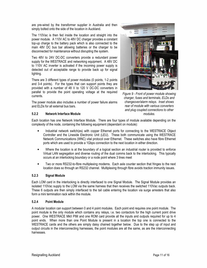
are pre-wired by the transformer supplier in Australia and then simply bolted onto the side of the location in Auckland.
The 110Vac is then fed inside the location and straight into the power module. A 110V AC to 48V DC charger provides a constant top-up charge to the battery pack which is also connected to the main 48V DC bus bar allowing batteries or the charger to be disconnected for maintenance without disrupting the system.
Two 48V to 24V DC-DC converters provide a redundant power supply for the WESTRACE and networking equipment. A 48V DC to 110V AC inverter is activated if the incoming power supply is detected out of acceptable range to provide back up for signal lighting.
There are 3 different types of power modules (0 points, 1-2 points and 3-4 points). For the types that can support points they are provided with a number of 48 V to 120 V DC-DC converters in parallel to provide the point operating voltage at the required currents.
The power module also includes a number of power failure alarms and ELDs for all external bus bars.
5.2.2 Network Interface Module
Each location has one Network Interface Module. There are four types of module available depending on the complexity of the node, containing the following equipment (dependant on module):
• Industrial network switch(es) with copper Ethernet ports for connecting to the WESTRACE Object Controller and the Lineside Electronic Unit (LEU). These both communicate using the WESTRACE Network Communications (WNC) vital protocol over Ethernet. These switches also have fibre Ethernet ports which are used to provide a 1Gbps connection to the next location in either direction.
• Where the location is at the boundary of a logical section an industrial router is provided to enforce Virtual LAN segregation and diverse routing of the dual comms back to the interlocking. This typically occurs at an interlocking boundary or a node point where 3 lines meet
• Two or more RS232-to-fibre multiplexing modems. Each axle counter section that fringes to the next location does so through an RS232 channel. Multiplexing through fibre avoids traction immunity issues.
5.2.3 Signal Module
Each LOM card in the interlocking is directly interfaced to one Signal Module. The Signal Module provides an isolated 110Vac supply to the LOM via the same harness that then receives the switched 110Vac outputs back. These 6 outputs are then simply interfaced to the tail cable entering the location via surge arresters that also form a mini termination rack within the module.
5.2.4 Point Module
A modular location can support between 0 and 4 point modules. Each point end requires one point module. The point module is the only module which contains any relays, i.e. two contactors for the high current point drive power. One WESTRACE MkII PIM and one ROM card provide all the inputs and outputs required for up to 4 point ends. When more than one Point Module is present in a location the top one is connected to the WESTRACE cards and the others are simply daisy chained together below. Due to the step up of input and output circuits in the interconnecting harnesses, the point modules are all the same, as are the interconnecting harnesses.
Figure 9 - Front of power module showing charger, fuses and terminals, ELDs and changeover/alarm relays. Inset shows rear of module with various converters and plug coupled connections to other
modules.

Resignalling Auckland Page 12 of 16
5.2.5 Axle Counter Interface Module
This module houses all the wiring required to power and interface the Frauscher axle counter equipment to a PIM and ROM. This includes circuits for track occupancy and vacancy, as well as reset commands from the interlocking. A “commissioning” button is also provided on the back of the module which allows overriding of the sweep logic in the interlocking under certain controlled circumstances.
5.2.6 General Purpose Input and Output Modules
These modules contain no special circuitry but just provide surge protected input and output termination points for generic 50V circuits. They are typically used for interfacing to level crossing locations and lockout zone control boxes.
5.3 Theory into Practice
Undoubtedly AMRP was not the first project to discover the promised benefits of a modular approach (regardless of its context) are not as easily extracted as they are sometimes initially anticipated. As with any new strategy, modular has its challenges in deployment, especially on a first attempt.
One thing that became evident very quickly on the project is that with modular, everything focuses around the logistics. If a last minute design alteration creates a shortage of a signal module or a specific type of harness, staff cannot just make one up on site with parts from a local supplier. This was mitigated as the project progressed by learning to have sufficient spares of all parts in stock running up to each commissioning and locking down design as early as possible.
It was also found that a modular solution needs time to become effective. There are obviously a lot of up front expenses with developing the system, the factory testing tools, safety cases and documentation. However other, more hidden, inefficiencies are involved in getting the whole deployment team to “think modular”. In the early stages of the project certain personnel even consider it a threat. However the team gradually gained trust that it was a technically sound solution they could trust. They saw it would allow them to spend less time on repetitive, boring tasks and instead focus on more interesting work. Eventually, it became the accepted norm.
There was a concern at the start of the project that the modular solution would not cater for all scenarios and therefore efficiencies would be lost by requiring miscellaneous free wiring for all the interfaces that had been ‘forgotten about’ when the system was specified. It is pleasing to report that this problem did not eventuate with probably less than 5% of locations having any free wiring in them.
The time taken for location build, installation and site testing have steadily reduced as the project has progressed and the teams learnt to use all the features of a modular system to their advantage. This has demonstrated that the modular approach is not necessarily an overnight efficiency gain, but one that grows with time and experience.
6 AUTOMATIC TRAIN PROTECTION
As part of the project a standard ETCS Level 1 solution is being implemented to provide ATP. New Zealand is a place where cross border interoperability with other nation’s railroads is never going to be a requirement, but ETCS was selected by KR so as to gain the benefits of a standard system with multiple supplier support in the future.
As with the production of the signalling principles, a number of collaborative workshops were held with KR’s signalling engineering team and operators to develop the ETCS principles for Auckland. At many stages throughout this process it was very tempting to customise the ETCS solution to make it fit better with existing KR rules. However, in each case some careful consideration always came to the same conclusion that the downsides of customisation outweighed the benefits proposed.
It may be questioned why a set of ETCS principles were needed at all if the ETCS standards were not going to be added to or “bent” for this project. The reason is that ETCS, even in its standard form, offers a variety of different methods to solve the same problem and is highly customisable. Choices must therefore be made, even from the standard options available.

Resignalling Auckland Page 13 of 16
6.1 Trackside fitment
All main signals including those provided for SIMBIDS movements are fitted with ETCS. Each signal has a balise group consisting of one fixed and one controlled balise. The controlled balise is driven by a Lineside Electronic Unit (LEU) in the object controller location case which can control up to 4 signal balise groups. By communicating via WNC with the WESTRACE object controller, the LEU knows the state of all signals and facing points for four block sections ahead. It uses this information to select the correct telegram to send to the train.
The system has been designed to minimise any adverse affect on operational performance as much as possible. This is to avoid the capital and ongoing maintenance costs associated with additional trackside equipment, such as infill balises, wherever possible. For example to take best advantage of the excellent braking characteristics of the new EMUs, the system has been configured with onboard calculated release speeds which will result in release speeds between 25-50% of line speed for the new EMUs. This still means that the system will be safely compatible with existing rolling stock if this is retro-fitted with ETCS in the future, albeit with more restrictive release speeds.
6.2 Onboard fitment
Due to a change of national government soon after the start of the project and subsequent change to procurement strategy for the EMUs, their delivery has been delayed until 2013. This means that the onboard fitment of ETCS equipment has not started yet.
Each 3 car EMU will be fitted with a single, centralised European Vital Computer (EVC) that drives the Invensys Balise Readers (IBR) and Driver Machine Interfaces (DMI) at each end of the train. Invensys Rail is currently working closely with the train builder CAF to integrate the ETCS equipment in the train at the earliest design stage. Installation and FAT testing will be completed at the CAF factory so that only minimal dynamic testing is left to complete for each unit when it arrives in NZ.
To provide a test vehicle for ETCS trackside commissioning prior to the arrival of the EMUs, ETCS has already been fitted to Driving Van Trailer (DVT) cab of a SD class push pull set. This cab enables the final commissioning of the trackside equipment before the first EMU arrives and for KR to test and validate the ETCS principles as early in the programme as possible.
7 TRAIN CONTROL
Before the project commenced, Auckland had a complex mix of control technologies in use and what can best be described as a fragmented overall control architecture. Two of the central stations had VPI electronic interlockings which were controlled by a local RealFlex unit lever VDU based control system. Papakura and Otahuhu were controlled by Westinghouse miniature Style L frames and Wiri had another Style L frame but was normally left switched out. Other relay interlocked junctions had remote control from a RealFlex unit lever panel in KiwiRail National Train Control centre in Wellington. All of these controlled areas were connected by dark territory automatic double line block sections with no single operator having overall live visibility of the whole system.
Figure 10 - Programming ETCS balises with their fixed telegrams. Controlled balises also have fixed telegrams in case of a cable or LEU
failure.

Resignalling Auckland Page 14 of 16
7.1 Centralised Train Control
AMRP includes the replacement of all existing control infrastructure with a new train control system with four terminals at KR’s National Train Control Centre in Wellington. Back-up local control desks are provided at Britomart. This is a disaster recovery measure in case the redundant links to Wellington are all lost or the train control centre in Wellington has to be evacuated in an emergency, such as an earthquake.
The new Rail 9000 train control system provides an instant increase in productivity with the introduction of route setting. This drastically reduces the number of mouse operations for complex route selection compared to the old unit lever arrangement where each set of points had to be controlled individually before a signal could be cleared. Also the ability for one operator to run the entire system during night time periods has reduced operational costs rather than having to staff individual boxes and panels.
The new system goes beyond simple train control functionality and also provides tools such as long route selection, time table integration for the train describer and a sophisticated Automatic Route Setting (ARS).
The train control system runs on two centralised servers that are co-located with the interlockings as shown in figure 2. These servers provide hot standby seamless changeover back-up for all services. Each of the workstations is a slave terminal that can be set up to an individual user’s preferences.
8 TESTING AND COMMISSIONING
The testing and commissioning strategy was a key consideration when planning the deployment of such a large and multi faceted project. Many of the technology decisions taken, such as the use of axle counters and modular signalling, were primarily driven by the need to work around a 24 hour railway and to make the process of testing and commissioning an “off shore” project as efficient as possible.
8.1 Modular Testing Approach
The modular equipment used within the object controller locations on this project was specifically designed to reduce site installation and testing time. As all the modules and harnesses are fully inspected, continuity and function tested in the factory where they are built, on site testing was limited to 3 activities;
1. Location case build verification;
2. Verification and function testing on site of field equipment (such as axle counters) and cable terminations;
3. A final full correspondence test of every input and output of the system back to the diagnostic and control systems.
Activity #3 is split into two phases; correspondence testing that can be completed prior to the commissioning while the existing signalling is still in operation and the remaining testing which can only be completed at commissioning, after final change over.
Figure 11 - One of the 3 train control overview screens that covers the Auckland network.

Resignalling Auckland Page 15 of 16
8.2 Minimum Commissioning Periods
Other than at Christmas, extended commissioning block of line periods were not available. Therefore, the project was engineered to maximise the amount of final correspondence testing that could be completed prior to the commissioning. This goal has been very successfully achieved on the project by completing the following prior to the commissionings:
• 100% of axle counters fully corresponded back to the panel prior to commissioning as they are an overlay system. Once this is completed they could also be monitored with existing trains which provided a few weeks of excellent soak testing prior to commissioning. This meant that the highest levels of reliability could be achieved from the train detection system post commissioning;
• To enable all signal aspects to be corresponded in advance, point detection simulators were developed that could be plug coupled onto the test port on each point module. This allows the panel tester to set any route on the new panel pre-commissioning and all points will appear to move to the required position, whereas on the ground nothing has actually moved;
• All signal aspects and route indicators are corresponded. Signals are all fitted with blanking front covers which block all light from any drivers, but allow a tester standing directly below the signal to see a thin line of light for each aspect. Therefore on commissioning nothing more than removing this cover was required for each signal;
• All interlocking functions are fully principles tested off site on an interlocking simulator.
This strategy meant that the only correspondence and principles testing required at the commissioning is:
• Correspondence of all points once changed over;
• Correspondence and principles testing of any fringes to existing signalling;
• Correspondence of any level crossings changed over on the commissioning and their associated DC track circuits.
In June 2011 due to a number of factors it became necessary to commission a very large area in one commissioning with only a 36 hour block of line. This commissioning of the SP 4a, 4b and 5a areas would effectively double the number of signalling assets under control of the new system. This was quite a challenge as the already commissioned areas of SP1a, Newmarket, SP1b and SP2 had been introduced over 4 separate previous commissionings. None of these had less than 48 hours for the block of line. It was therefore felt necessary to introduce some further measures to remove work from the final commissioning period, including:
• Pre-changeover where possible of old point machines with the new type prior to commissioning on nights which required power modifications to the existing interlocking circuits.
• Double studding of control and detection circuits on all point machines for old and new circuits. This allowed the point simulators to be removed and links inserted at night to perform all correspondence testing to the new interlocking prior to commissioning. On the commissioning only a very quick Normal/Reverse confidence test was required after the original tail cables were disconnected and final wire count completed. This also meant no contingency allowance needed to be provided in the commissioning program for points.
• A switchable fringe circuit was employed. By changing of links in the fringe location it allowed for either the new or old fringe circuits to be connected to the existing location. In this way the fringe could be fully corresponded and principles tested prior to the commissioning.
All of these extra mitigations proved to be superbly effective in slashing the time requirements and reducing the risk profile for the actual commissioning to an extremely low level. This resulted in the commissioning being completed within the allotted 36 hours. This was quite an achievement as it involved bringing 314 SEUs including 90 point changeovers and 131 axle counters, into revenue service.

Resignalling Auckland Page 16 of 16
8.3 Testing outcomes
Surely the holy grail of any signalling project is to complete all testing prior to the actual commissioning, thereby reducing the block of line hours to a minimum? Achieving maximum pre-testing also reduces the risk for the part of any project’s lifecycle where additional time is often not available for unplanned hiccups.
The Auckland project has successfully proved that it is possible to achieve this minimal commissioning goal through such techniques as:
• The adoption of overlay technologies;
• Full signal replacement;
• Using the capacity of new CBIs advantageously, and;
• The use of modular signalling and other special testing strategies to mitigate the remaining technical risks at the commissioning such as point simulators and switchable fringe interface circuitry.
Another finding from the testing was that the use of modular location technology resulted in zero faults being detected with the location circuits. Therefore, no contingency time for this testing needed to be allowed in the program. The only area where problems were encountered on the commissioning was with the immunisation of existing LX locations. Even with very thorough pre-testing and correlation it was impossible to remove all the risk of further anomalies being found at commissioning and thereby putting the commissioning timeframe at risk.
9 CONCLUSION
The resignalling of Auckland will be completed in June 2012. This project has demonstrated what can be achieved when a full renewal strategy is adopted. It has shown how innovative thinking can bring operational functionality and commissioning benefits to the science of traditional signalling projects.
9.1 Hindsight
The success of the ‘renewal over upgrade’ mantra on a macro level for the whole project was contradicted by the test and commissioning challenges at the micro level. Small packets of work to immunise rather than replace LX locations proved to be one of the most time consuming, costly and highest risk activities on the project. This would have been mitigated by avoiding the reuse of even just a small amount of existing equipment.
Another area where interesting lessons have been learnt is with the concept of modularisation. Here the lesson was not to underestimate the initial investment level required or the practice needed to adapt skill sets and thinking to fit around the logistics centric world of modular signalling.
9.2 Positives
Interestingly, areas which were considered as high risk, such as engineering innovation and new products like WESTRACE MkII and modular signalling actually performed extremely well and have delivered great benefits to the project team and customer.
The project also demonstrated that when the commissioning and technology strategy is right, this should be capitalised upon by making commissionings as big as possible. This may seem counter intuitive from a risk point of view but the successes described in this paper support the argument that one very large but extremely well planned commissioning with full overlay technologies is less risky that a number of smaller more bespoke ones.
Ultimately the project has delivered its promise of a brand new signalling system, to a whole city, with cutting edge levels of system availability, modularisation, control technology and safety.