NNG-Honda 8 - NAV-TV
14
NNG-Honda 8 Navigation interface for select Honda vehicles NTV-KIT582 3950 NW 120 th Ave, Coral Springs, FL 33065 TEL 561-955-9770 FAX 561-955-9760 NTV-DOC220
Transcript of NNG-Honda 8 - NAV-TV
NNG-Honda 8Navigation interface for select Honda vehicles
NTV-KIT582
3950 NW 120th Ave, Coral Springs, FL 33065 TEL 561-955-9770 FAX 561-955-9760
NTV-DOC220
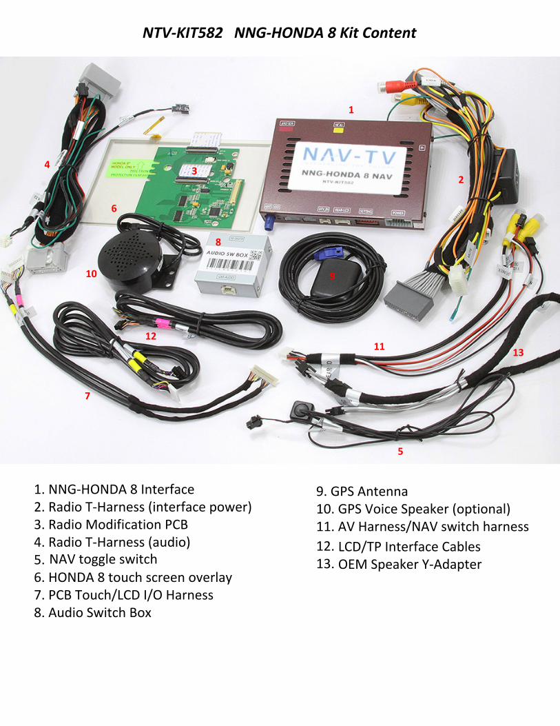
NTV-KIT582 NNG-HONDA 8 Kit Content
1. NNG-HONDA 8 Interface2. Radio T-Harness (interface power)3. Radio Modification PCB4. Radio T-Harness (audio)5.6. HONDA 8 touch screen overlay7. PCB Touch/LCD I/O Harness8. Audio Switch Box
9. GPS Antenna10. GPS Voice Speaker (optional)11. AV Harness/NAV switch harness
1
234
5
7
6
8
910
11
12.13.
LCD/TP Interface CablesOEM Speaker Y-Adapter
1213
NAV toggle switch

Installation GuideNavigation Honda 8"
Touch Screen Calibrationsetup MAP PAth
FAQBasic Trouble Shoot
Remove side panel Remove AC Vent Panel
Remove 3 screws Take out Screen
Honda Odyssey Dash Removal
Remove 4 screwsTake out LCD Panel
Get ready to place1. video board2. touch screen panel
NTV-DOC220
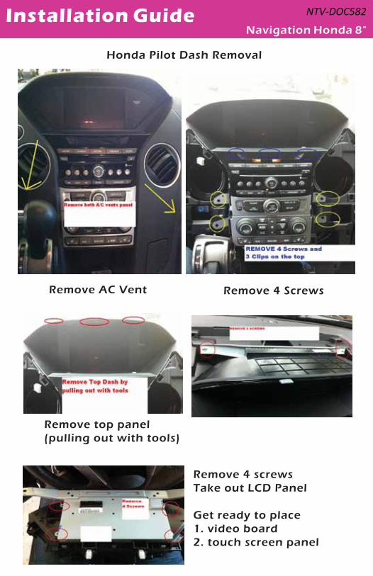
Installation GuideNavigation Honda 8"
Remove AC Vent Remove 4 Screws
Honda Pilot Dash Removal
Remove top panel(pulling out with tools)
Remove 4 screwsTake out LCD Panel
Get ready to place1. video board2. touch screen panel
NTV-DOC582

Installation GuideNavigation Honda 8"
Remove Front Bezel
Use pick tools to remove LCD Casing
Install Touch Screen Panel Board
unscrew factory video boardand get ready to take off LCD panel
Remove Video Board screwsand 2 ribbon cable
Place Touch Screen Panelon in fron the LCD Panel
NTV-DOC582
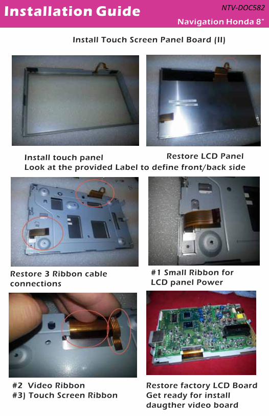
Installation GuideNavigation Honda 8"
Install touch panelLook at the provided Label to define front/back side
Restore 3 Ribbon cable connections
Install Touch Screen Panel Board (II)
#1 Small Ribbon forLCD panel Power
Restore factory LCD BoardGet ready for install daugther video board
Restore LCD Panel
#2 Video Ribbon #3) Touch Screen Ribbon
NTV-DOC582
Installation Guide NTV-DOC220
Navigation Honda 8"
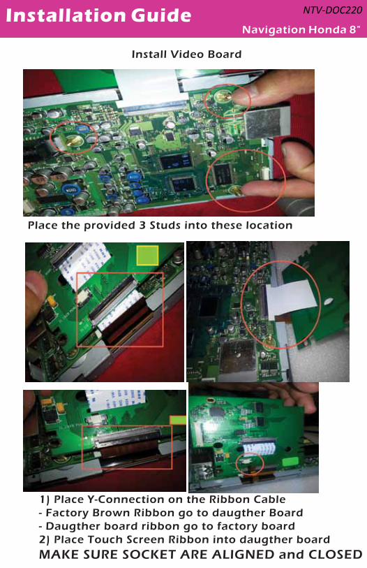
Place the provided 3 Studs into these location
Install Video Board
1) Place Y-Connection on the Ribbon Cable- Factory Brown Ribbon go to daugther Board- Daugther board ribbon go to factory board2) Place Touch Screen Ribbon into daugther boardMAKE SURE SOCKET ARE ALIGNED and CLOSED

Installation GuideNavigation Honda 8"
Restore 3 factory screws into daugther board
Install Video Board II
Peel off Metal TapeGet the Panel casing
Go thru video cablefrom interface module tothe daugther board
Secure video connection
NTV-DOC220
Installation GuideNavigation Honda 8"
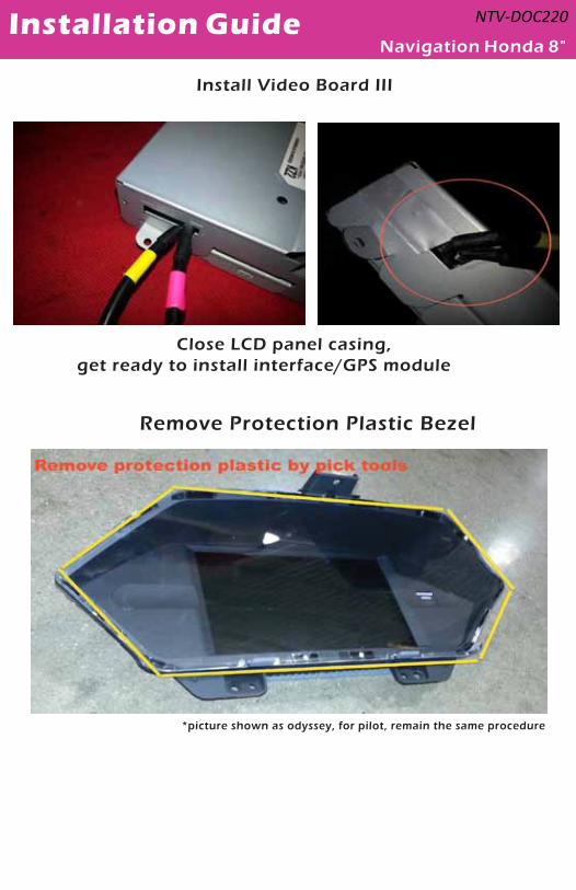
Close LCD panel casing, get ready to install interface/GPS module
Install Video Board III
*picture shown as odyssey, for pilot, remain the same procedure
Remove Protection Plastic Bezel
NTV-DOC220
Installation GuideNavigation Honda 8"
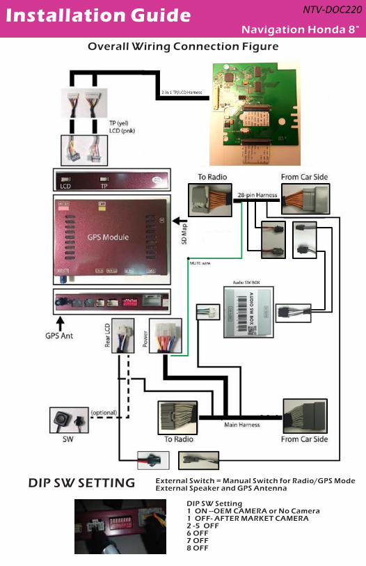
Overall Wiring Connection Figure
DIP SW Setting1 ON --OEM CAMERA or No Camera 1 OFF- AFTER MARKET CAMERA 2 -5 OFF6 OFF7 OFF8 OFF
DIP SW SETTING External Switch = Manual Switch for Radio/GPS ModeExternal Speaker and GPS Antenna
NTV-DOC220
Installation Guide NTV-DOC220
Navigation Honda 8"
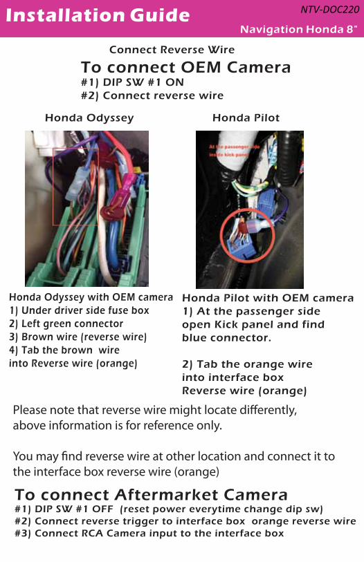
Connect Reverse Wire
Honda Odyssey Honda Pilot
To connect OEM Camera#1) DIP SW #1 ON#2) Connect reverse wire
Honda Pilot with OEM camera1) At the passenger sideopen Kick panel and find blue connector.
2) Tab the orange wireinto interface box Reverse wire (orange)
Honda Odyssey with OEM camera1) Under driver side fuse box2) Left green connector3) Brown wire (reverse wire)4) Tab the brown wireinto Reverse wire (orange)
Please note that reverse wire might locate di�erently,above information is for reference only.
You may �nd reverse wire at other location and connect it to the interface box reverse wire (orange)
To connect Aftermarket Camera#1) DIP SW #1 OFF (reset power everytime change dip sw)#2) Connect reverse trigger to interface box orange reverse wire #3) Connect RCA Camera input to the interface box

WEAK /NO GPS SIGNAL?
Tips to Improve GPS Antenna Signal if vehicle equipped Metallized Windshield*
“GPS MONITOR Tools”
Exit IGO MAP by press SHUT DOWN BUTTON
Console> SETUP GPS MONITOR
Locate the Antenna with minimum 5 bars in dark blue or Gray bar
(Always suggest mounting the GPS antenna on the roof)
Press “!” icon to reset GPS signal and change the Antenna position
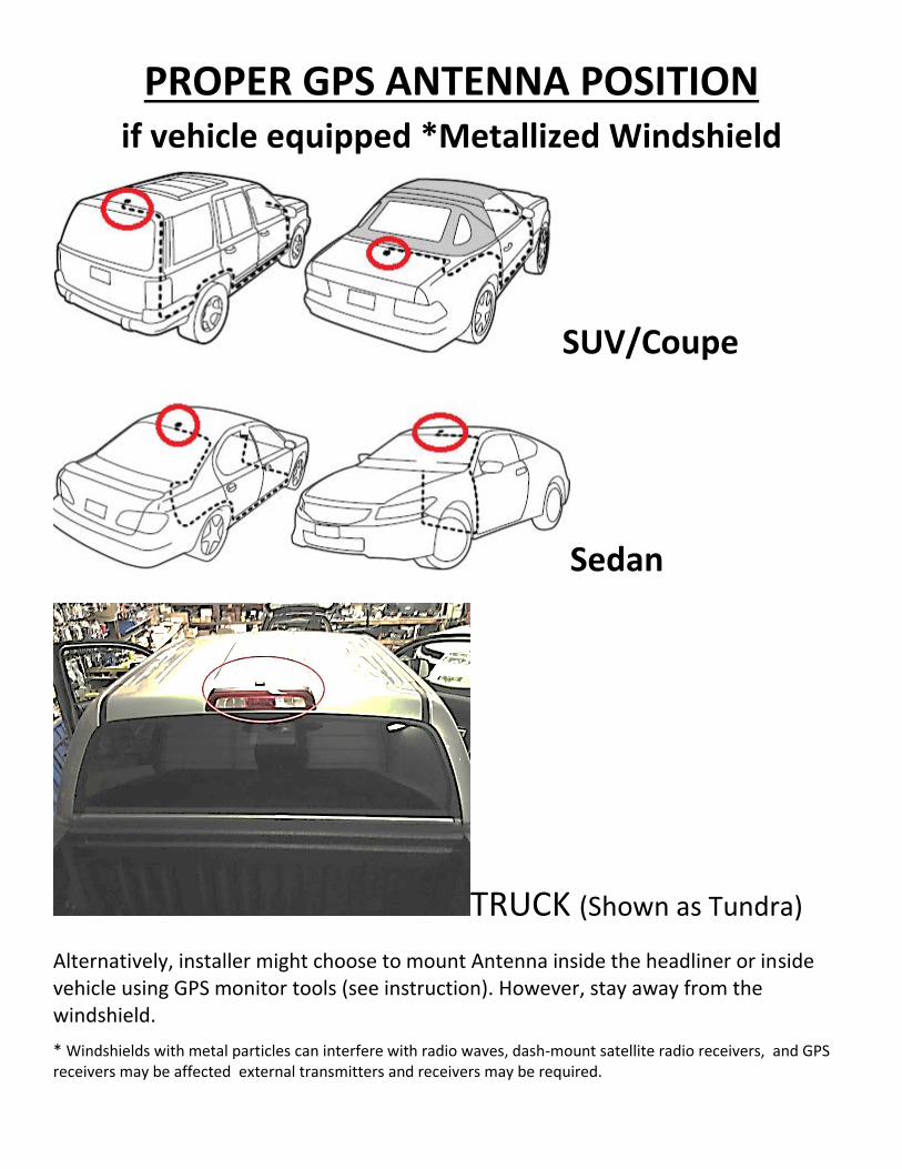
PROPER GPS ANTENNA POSITION if vehicle equipped *Metallized Windshield
SUV/Coupe
Sedan
TRUCK (Shown as Tundra)
Alternatively, installer might choose to mount Antenna inside the headliner or inside vehicle using GPS monitor tools (see instruction). However, stay away from the windshield.
* Windshields with metal particles can interfere with radio waves, dash-mount satellite radio receivers, and GPSreceivers may be affected external transmitters and receivers may be required.
IGO PRIMO MAP PATH SETTING
1. Press Setup ‐> Navigate Setup
2. Press on the Folder Icon
3. Select the following path in Storage Card ‐> cyb_navi.exe
4. Press HOME button on the top left corner and press
NAVIGATION
5. System should able to run into “IGO PRIMO”