NI Trend Watch 2014 - National Instruments
9
NI Trend Watch 2014 Technology Trends That Accelerate Your Productivity The Cyber-Physical Design Challenge Big Analog Data ™ —The Biggest Big Data The SDRification of RF Instrumentation The Evolution of System-Level Design Using Mobile Devices as Remote UIs Making Waves in Technology Education
Transcript of NI Trend Watch 2014 - National Instruments

NI Trend Watch 2014Technology Trends That Accelerate Your Productivity
The Cyber-Physical Design Challenge
Big Analog Data™—The Biggest Big Data
The SDRification of RF Instrumentation
The Evolution of System-Level Design
Using Mobile Devices as Remote UIs
Making Waves in Technology Education

Technology Trends You Need to Know
Since the founding of National Instruments in 1976, our mission has been to equip engineers and scientists with tools that accelerate productivity, innovation, and discovery. To do this, we closely monitor trends across industries and draw on this insight to develop tools that integrate the ever-increasing power of available technology.
Because NI tools are used in so many different industries and applications, NI is in a position to examine the latest trends in measurement, sensors, networks, test, and more—as they happen. We compiled what we learned in this report to help you take advantage of the latest technological breakthroughs and stay ahead of the competition.
NI isn’t just a supplier—we’re a technology adviser. We hope this information helps you be more productive and focused on what you were hired to do.
—Eric Starkloff, Senior Vice President of Global Sales and Marketing, National Instruments
Contents
Cyber-Physical Systems
THE CYBER-PHYSICAL DESIGN CHALLENGE
Developing systems that continuously and dynamically interact with their environments through the coupling of distributed computational and physical components
Big Analog Data
BIG ANALOG DATA™—THE BIGGEST BIG DATA
Connecting IT infrastructures and analytic tools, such as the cloud, with data acquisition systems to make faster decisions on test data
RF/Wireless
THE SDRIFICATION OF RF INSTRUMENTATION
Revolutionizing the wireless industry by integrating a range of technologies from software defined radio into RF test equipment
Models of Computation
CHANGE THE WAY YOU THINK: THE EVOLUTION OF SYSTEM-LEVEL DESIGN
Integrating multiple programming approaches into a single environment to simplify complex distributed and real-time applications
Mobile Communication
USING MOBILE DEVICES AS REMOTE UIs IN MEASUREMENT AND CONTROL SYSTEMS
Designing systems accessible at any time, from any place, from any device
STEM Education
MAKING WAVES IN TECHNOLOGY EDUCATION
Preparing students with cross-disciplinary approaches to engineering
This cyber-physical system is a complete control system created with test and measurement hardware, controlled by software, to treat cancer using hadron therapy.
CPSs are too complicated to be designed using disparate tools and techniques. Central to solving the cyber-physical design challenge is designing beyond implementation and instead at the system level. White House Assistant Director for Robotics and Cyber-Physical Systems Dr. Vijay Kumar underscores this importance, stating there is “an urgent need to develop design methodologies that will provide real-time, guaranteed performance in cyber-physical systems.” Engineers need tools for the holistic design of the system and its interactions with the real world.
For example, in 2003 a three-day electrical blackout affected 55 million people in the northeastern United States. Power flow modeling tools used to analyze the physical properties of the power grid did not model the behavior of the automatic control systems, nor the network effect of cascading shutdowns. This exemplifies the need for holistic design in cyber-physical systems. CPS design methodologies enable you to model and explore the interactions between the cyber and physical worlds, helping to identify and prevent these and other types of failures that may otherwise remain hidden.
SOLVING THE CYBER-PHYSICAL DESIGN CHALLENGE
One of the proven methodologies for meeting the cyber-physical design challenge is model-based design, which emphasizes modeling to design, analyze, verify, and validate dynamic systems. Engineers derive models from system specifications and the analysis of the environment and use them to design, simulate, synthesize, and test a CPS. These modeling techniques illuminate the interplay of practical design with formal models of systems that incorporate both physical dynamics and computation. The manual integration and deployment of these models are costly, time-consuming, and error prone. System design tools with the right levels of abstraction allow cyber and physical models to be automatically combined, simulated, and deployed, and the same models are adaptable for requirements tracking and hardware-in-the-loop verification.
Another proven design methodology for CPSs is platform-based design, which was pioneered at the University of California, Berkeley. It is used widely across the automotive and aerospace industries to plan and build platforms that scale to large complex systems with long life spans. You can use a platform as an abstraction layer to think about application-level constraints without concerning yourself with implementation refinements. With the right levels of abstraction, you may separate design concerns by defining platform elements with clear interconnections, which results in highly componentized, composable, and modularized designs. Clear interconnections make it possible for you
to replace or upgrade platform elements with commercial off-the-shelf hardware to decrease development costs and simplify life-cycle management. You can reuse, repurpose, retool, or leverage platform elements for test frameworks, requirements tracking, verification, and documentation. Platform-based design and model-based design are complementary design methodologies that are often used in parallel. When you adopt a system design tool, you adopt a platform that unifies design methodologies, spans multiple levels of abstraction and multiple models of computation, reduces the cost of integration, and accelerates the innovation of your next platform.
Better CPS designs are achievable with disciplined design methodology, holistic development tools, and commercial off-the-shelf hardware. Returning to the example of the carriage brake lever, note how a once simple design can evolve into a ubiquitous and complex CPS. This begs the question: What levers are you designing today, how will they evolve into the complex systems of tomorrow, and do you have the right design tools to make that tomorrow a reality?
CYBER-PHYSICAL SYSTEMS 5
Com
puta
tion
Comm
unication
Control
Vehicle-to-Vehicle
Emergency Services
Satellite
Adaptive CruiseBraking
Stability
Aut
omat
ic T
rans
m
ission
Onl
ine
Dia
gn
ostics
Ente
rtai
nm
ent
The Cyber-Physical Design ChallengeModern engineered systems are rarely designed once, rarely designed in isolation, and rarely ever complete. The braking mechanism in your car evolved from the mechanical lever brake on horse carriages and was soon enhanced with hydraulics to improve braking power and stability. Electrical components were introduced with the advent of power-assisted brakes. Antilock brakes began as mechanical feedback control systems to prevent airplane wheels from locking and eventually migrated to automobiles. Today, automobile brakes incorporate electronic stability control, traction control, adaptive cruise control, emergency brake assist, and more. What was once a lever is now a system comprising distributed computers; independently braked wheels; and the sensing of human input, vehicle performance, and obstacles in the environment. Vehicles themselves are components of larger systems, interacting with urban traffic monitoring and control systems that adapt traffic lights, express lanes, and metering to meet social demand. Another example is the telescope, first constructed from two glass lenses; today, more than 8,000 mirrors are actuated every few milliseconds by a distributed network of computers in the Extremely Large Telescope at the European Southern Observatory. Over time, stand-alone products are replaced with platforms, and even the simplest “lever level” designs evolve into dynamic, interdependent systems.
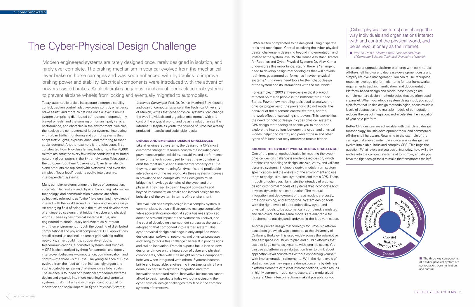
Many complex systems bridge the fields of computation, information technology, and physics. Computing, information technology, and communication systems are often collectively referred to as “cyber” systems, and they directly interact with the world around us in new and valuable ways. An emerging field of science is the study and development of engineered systems that bridge the cyber and physical worlds. These cyber-physical systems (CPSs) are engineered to continuously and dynamically interact with their environment through the coupling of distributed computational and physical components. CPS applications are all around us and include smart grid, vehicle traffic networks, smart buildings, cooperative robots, telecommunications, automotive systems, and avionics. A CPS is characterized by three fundamental and deeply interwoven behaviors—computation, communication, and control—the three Cs of CPSs. The young science of CPSs evolved from the need to meet increasingly urgent and sophisticated engineering challenges on a global scale. The science is founded on traditional embedded systems design and expands into more meaningful and complex systems, making it a field with significant potential for innovation and social impact. In Cyber-Physical Systems:
Imminent Challenges, Prof. Dr. Dr. h.c. Manfred Broy, founder and dean of computer science at the Technical University of Munich, writes that cyber-physical systems “can change the way individuals and organisations interact with and control the physical world, and be as revolutionary as the internet.” Despite its youth, the science of CPSs has already produced impactful and actionable results.
UNIQUE AND EMERGENT DESIGN CHALLENGES
Like all engineered systems, the design of a CPS must overcome stringent resource constraints including cost, power consumption, reliability, scalability, and performance. Many of the techniques used to meet these constraints omit the most unique and fundamental property of CPSs: they must achieve meaningful, dynamic, and predictable interactions with the real world. As these systems increase in prevalence and complexity, their designers must bridge the knowledge domains of the cyber and the physical. They need to design beyond constraints and beyond implementation details and instead design for the behaviors of the system in terms of its environment.
The evolution of a simple design into a complex system is commonplace, but we still struggle to manage complexity while accelerating innovation. As your business grows so does the size and impact of the systems you deliver, and the cost of developing a component surpasses the cost of integrating that component into a larger system. This cyber-physical design challenge is only amplified when designs span software, networks, and physical processes, and failing to tackle this challenge can result in poor designs and stalled innovation. Domain experts focus less on new design and more on the integration of cyber and physical components, often with little insight on how a component behaves when integrated with others. Systems become brittle and intractable; engineering investments shift from domain expertise to systems integration and from innovation to standardization. Innovative businesses cannot afford to design products today without anticipating the cyber-physical design challenges they face in the complex systems of tomorrow.
¢¢ The three key components of a cyber-physical system are computation, communication, and control.
ni.com/trendwatch
[Cyber-physical systems] can change the way individuals and organisations interact with and control the physical world, and be as revolutionary as the internet.¢¢ Prof. Dr. Dr. h.c. Manfred Broy, Founder and Dean of Computer Science, Technical University of Munich
TABLE OF CONTENTS

BIG ANALOG DATA 7
Big Analog Data™—The Biggest Big Data
¢¢ Big Analog Data challenges include sensors and actuators, DAQ and analysis systems, and IT infrastructures.
In test, measurement, and control applications, engineers and scientists can collect vast amounts of data in short periods of time. When the National Science Foundation’s Large Synoptic Survey Telescope comes online in 2016, it should acquire more than 140 terabytes of information per week. Large gas turbine manufacturers report that data from instrumented electricity generating turbines, while in manufacturing test, generate over 10 terabytes of data per day. In one asset monitoring application cited in the October 2013 Automation World article “Big Data: Sweat the Little Stuff,” 152,000 sensor samples are taken every second, accumulating up to 4 trillion samples in a single year. New York Times blogger Nick Wingfield wrote in his March 12, 2013, post that real estate companies use GPS signals from as many as 100 million drivers to determine driving times in prospective neighborhoods. These are examples of the “big data” trend.
But the amount of data is not the only trait of big data. In general, big data is characterized by a combination of three or four “Vs”—volume, variety, velocity, and value. An additional “V,” visibility, is emerging as a key defining characteristic. That is, a growing need among global corporations is geographically dispersed access to business, engineering, and scientific data. For example, data acquired from instrumented agricultural equipment in a rural midwestern field in the United States may undergo analysis by data scientists in Europe. Or product test engineers in manufacturing lines in South America and China may need access to each other’s data to conduct comparative analysis. This results in demand for interconnected information technology (IT) systems, such as the cloud, to be intimately connected to DAQ systems.
CHARACTERIZING BIG ANALOG DATA INFORMATION
Big Analog Data information is a little different from other big data, such as that derived in IT systems or social data. It includes analog data on voltage, pressure, acceleration, vibration, temperature, sound, and so on from the physical world. Big Analog Data sources are generated from the environment, nature, people, and electrical and mechanical machines. In addition, it’s the fastest of all big data since analog signals are generally continuous waveforms that require digitizing at rates as fast as tens of gigahertz, often at large bit widths. And, it’s the biggest type because this kind of information is constantly generated from natural and man-made sources. Consider the unceasing light,
sound, motion, and electromagnetic waves throughout the world, solar system, and universe.
According to IBM, a large portion of the big data today is from the environment, “including images, light, sound, and even the radio signals—and it’s all analog.” And the analog data the Square Kilometre Array (SKA) collects from deep space is expected to produce 10 times that of the global Internet traffic.
THE 3-TIER BIG ANALOG DATA SOLUTION
Drawing accurate and meaningful conclusions from such high-speed and high-volume analog data is a growing problem. This data adds new challenges to data analysis, search, data integration, reporting, and system maintenance that must be met to keep pace with the exponential growth of data. Solutions for capturing, analyzing, and sharing Big Analog Data work to address the combination of conventional big data issues and the difficulties of managing analog data. To cope with these challenges—and to harness the value in analog data sources—engineers are seeking end-to-end solutions.
Specifically, engineers are looking for three-tier solution architectures, as depicted in the figure, to create a single, integrated solution that adds insight from the real-time capture at the sensors to the analytics at the back-end IT infrastructures. The data flow starts in tier 1 at the sensor and is captured in tier 2 system nodes. These nodes perform the initial real-time, in-motion, and early-life data analysis. Information deemed important flows across “The Edge” to traditional IT equipment. In the IT infrastructure, or tier 3, servers, storage, and networking equipment manage, organize, and further analyze the early-life or at-rest data. Finally, data is archived for later use. Through the stages of data flow, the growing field of big data analytics is generating never-before-seen insights. For example, real-time analytics are needed to determine the immediate response of a precision motion control system. At the other end, at-rest data can be retrieved for analysis against newer in-motion data, for example, to gain insight into the seasonal behavior of a power generating turbine. Throughout tiers 2 and 3, data visualization products and technologies help realize the benefits of the acquired information.
Considering that Big Analog Data solutions typically involve many DAQ channels connected to many system nodes, the capabilities of reliability, availability, serviceability, and manageability (RASM) are becoming more important. In general, RASM expresses the robustness of a system related to how well it performs its intended function. Therefore, the RASM characteristics of a system are crucial to the quality of the mission for which the system is deployed. This has a great impact on both technical and business outcomes. For example, RASM functions can aid in establishing when preventive maintenance or replacement should take place. This, in turn, can effectively convert a surprise or unplanned outage into a manageable, planned outage, and thus maintain smoother service delivery and increase business continuity.
The serviceability and management are similar to that needed for PCs and servers. They include discovery,
deployment, health status, updates, security, diagnostics, calibration, and event logging. RASM capabilities are critical for reducing integration risks and lowering the total cost of ownership because these system nodes integrate with tier 3 IT infrastructures.
The oldest, fastest, and biggest big data—Big Analog Data—harbors great scientific, engineering, and business insight. To tap this vast resource, developers are turning to solutions powered by tools and platforms that integrate well with each other and with a wide range of other partners. This three-tier Big Analog Data solution is growing in demand as it solves problems in key application areas such as scientific research, product test, and machine condition and asset monitoring.
Tier 1 Tier 2 Tier 3
Sensors/Actuators
(Point of Data Acquisition/Control)
System Nodes
(Data Acquisition and Analysis, Control, Monitoring, Test)
Hardware and Firmware
IT Infrastructure Servers, Storage, Workstations
(Analytics, Databases, Archives)
Edge IT (Local, Remote, Cloud) Corporate/Federated IT
Software
Th
e E
dg
e
Data FlowReal-Time In Motion Early Life At Rest Archive
ni.com/trendwatch
The oldest, fastest, and biggest big data— Big Analog Data—harbors great scientific, engineering, and business insight.
TABLE OF CONTENTS

RF/WIRELESS 9
The SDRification of RF Instrumentation
SDRified Instrument
SD
R
Defi
nin
g A
ttri
bu
tes
+ Agile RF front end
+ Integrated Tx and Rx
+ Accessible DSP technology
Instru
men
t
Defi
nin
g Attrib
utes
+ NIST-traceable calibration
+ Measurement algorithms
+ Automation API
¢¢ The modern “SDRified” instrument has many of the defining attributes of both an SDR and a classic instrument.
The modern RF instrument has evolved from merely a measurement device into a premier tool for system design. This evolution was fueled by a broad range of technologies from the software defined radio (SDR). The flexibility of the SDR is revolutionizing not only the wireless industry but also RF test equipment. In the late 1980s, engineers began to experiment with the idea of the SDR. Historically, radios relied on complex analog circuitry not only for the transmission and reception of signals at RF and microwave frequencies but also for the encoding and decoding of the message signal. The idea of the SDR was to use a general-purpose wireless radio for transmission and reception while executing many of the physical layer functions (such as modulation and demodulation) in software.
Some of the first significant incarnations of the SDR were military radio communications programs such as the SPEAKeasy program in the early 1990s, according to “Software Defined Radio: Origins, Drivers and International Perspectives” by Walter H.W. Tuttlebee. Radios designed as part of this program offered interoperability between various air interfaces by implementing many of the modulation and demodulation functions in software.
However, by the late 1990s, engineers were actively researching the use of SDR technology in commercial systems such as cellular base stations. One of the most influential papers that described the requirements of SDRs for an ever increasing range of applications was “Software Radios: Survey, Critical Evaluation and Future Directions” by Dr. Joseph Mitola III and published in IEEE Spectrum in 1993. As a result of his extensive research, Dr. Mitola is widely known as the “Father of SDR.”
Modern base stations are perhaps the best embodiment of the benefits of the SDR approach. As wireless standards evolved from GSM through LTE, it became increasingly more difficult to add support for new standards with more hardware. In addition, base stations use sophisticated and evolving software for signal processing and closed-loop control. For example, power amplifier (PA) linearization techniques such as digital predistortion (DPD) are not only essential to the base station’s performance but also constantly improving over time. As a result, the SDR approach is ideal for base station design and long-term supportability.
FUNDAMENTAL CHANGES TO INSTRUMENTATION
At the same time the adoption of the SDR architecture was increasing in the wireless industry, RF test and measurement equipment was undergoing a significant evolution. In the early 2000s, the onslaught of new wireless standards required instruments to offer an increasing breadth of measurement capabilities, which led to a more flexible architecture. Given the variety of RF measurements engineers were required to make, the historical practice of designing an instrument for a relatively narrow range of applications became impractical. As a result, test vendors began to explore the concept of software-defined RF test equipment.
The evolution of the traditional swept-tuned spectrum analyzer marks one of the most dramatic examples of an industry-wide transition to software-defined instrumentation. In a traditional spectrum analyzer, functions such as the resolution bandwidth filters and power detection were implemented using analog components. Today, however, the modern RF signal analyzer incorporates a general-purpose RF downconverter (a radio) to produce digitized I/Q samples. Internally, the instrument processes I/Q samples in a variety of ways including the computation of a spectrum. As a result, the same signal analyzer that engineers might use to perform a spectrum measurement can also be used to decode a RADAR pulse, demodulate an LTE signal, or even record a GPS signal off the air.
Today, test vendors have further refined the architectures of RF instruments to increasingly resemble that of the SDR. The fundamental architecture of the new generation of RF instruments incorporates not only a general-purpose radio but also a wide range of PC and signal processing technologies such as multicore CPUs and FPGAs. This “SDRification” of today’s RF test equipment provides substantial benefits in traditional RF test applications while helping engineers use applications that were previously impossible to solve with RF instrumentation.
THE IMPACT OF MOORE’S LAW ON RF TEST
The consistent improvement in instrument signal processing performance is one of the most obvious benefits of integrating PC technology into RF instrumentation. Moore’s law predicts constant improvements in CPU processing power, which means similar improvements in instrument processing performance. Thus, as CPU vendors continue to innovate on processor technology, PC-based instruments benefit by achieving faster measurement speeds. For example, the same spectrum measurement that took 50 ms a decade ago can now be performed in less than 5 ms.
In addition to the CPU, modern RF instruments increasingly incorporate a core technology of the modern SDR—the FPGA. Although RF instruments have used FPGAs for more than a decade, an evolving approach is to make the instruments’ FPGAs user programmable. User-programmable FPGAs are expanding the role of instrumentation from a single-function device to an infinitely flexible closed-loop control system.
With today’s FPGA-enabled instruments, engineers can marry the real-time control capabilities of the FPGA with the time-critical functions of testing. For example, in test applications that require device control through a digital interface, an FPGA-enabled instrument can synchronize digital device control with the execution of the RF measurements. As a result of the new testing approaches offered by user-programmable FPGAs, engineers can see test time improvements of up to 100X.
The benefits of FPGA-enabled instruments have also driven significant innovation in the FPGA programming experience. Although some engineers have used hardware description languages such as VHDL for years, the complexity of FPGA programming is often a barrier for widespread adoption.
EXPANDING APPLICATIONS FROM “SDRIFICATION”
Finally, the SDR-like architectural elements of today’s RF instrumentation have blurred the line between instrument and embedded platforms. Defining instrument characteristics such as a user-programmable FPGA have led to a rapid rise in the number of RF instruments used in embedded applications.
Twenty years ago, it seemed unimaginable to assemble a million dollar collection of RF signal generators and RF signal analyzers to prototype a RADAR system. Not only was such a system cost and size prohibitive, but the instrument programming experience prevented engineers from using the instruments like a radio.
Today, however, more compact and powerful PC-based instrument platforms such as PXI are ideal prototyping solutions for electronic embedded systems. PC-based instruments not only meet the size and cost requirements of embedded systems, but they also offer a software experience that helps engineers reconfigure an RF instrument for a wide range of uses. Now engineers are designing embedded systems such as RADARs, channel emulators, GPS recorders, and DPD hardware with RF signal generators and analyzers.
The ability to fully define and customize the behavior of RF instrumentation with software is a key element to solving the next generation of test challenges. As a result, the architecture of tomorrow’s RF instruments will look more and more indistinguishable from that of the SDR.
ni.com/trendwatch
Today, test vendors have further refined the architectures of RF instruments to increasingly resemble that of the SDR.
TABLE OF CONTENTS

MODELS OF COMPUTING 11
.c .vi .m .bit
Change the Way You Think: The Evolution of System-Level Design
¢¢ This evolution of system-level design demands software that can abstract multiple models of computation and allow them to be used together. This empowers you to develop each component of the application in the appropriate language in a familiar environment, but integrate them without knowing the details of each component.
Simply put, a model of computation is one of many languages or development approaches for solving complex issues. Whether it’s exploring new sources of renewable energy or advanced cancer research, the complexity of the problems that today’s engineers face continues to escalate. As a result, a single solution can sometimes require the integration of several models of computation. However, in most cases, engineers are typically trained professional developers in only a single language. To efficiently and effectively solve these increasingly complex issues, the mental model used by today’s engineer must evolve.
THE TRADITIONAL APPROACH TO SYSTEM DESIGN
Today’s complex design spans multiple knowledge domains. Consider the testing of a cyber-physical system like a smart appliance. This once “simple” application requires domain knowledge in a handful of RF standards, power management, physical design, heat dissipation, image capture and analysis, and potentially video quality. In the traditional test market, each of these functions requires testing by a different domain expert using disparate tools, which then creates artificial boundaries between the experts. Each expert works in his own language, with no common ground between the tools. Not only is the cost of integrating these languages complex and expensive, both in true cost and time spent, but the process of integrating these approaches provides no real value to the system being designed.
These disparate tools also drastically limit the scalability of the system, and any modularity is lost because the time spent integrating must be re-realized when one of the individual domain components changes. This could of course be avoided if each of the domain-specific developers keeps in mind the larger overall design requirements, but that too requires a shift in the approach. Consider the following from “Taming Heterogeneity—the Ptolemy Approach” by Edward Lee which he discusses emergent behavior as the inability of the author of an individual model to properly anticipate the needs of the integration of that model with other languages:
One example of an emergent behavior is priority inversion between threads in a real-time operating system. In this case threads are interacting using two different communication mechanisms: mutual exclusion using monitors and a fixed priority scheduling mechanism. Looking at each mechanism in isolation, a designer naturally expects that the thread scheduler will preempt
low-priority threads when a high-priority thread is ready to execute. Instead, by locking a monitor, a low-priority thread may stall a high-priority thread for an unbounded amount of time.
This ability to properly anticipate integration needs beyond the tool of expertise is difficult and causes developers distress because they now need to both learn and consider these requirements that are outside their established areas of expertise. The lack of interoperability between domain tools further complicates that consideration.
THE REQUIRED EVOLUTION TO SYSTEM DESIGN
This is where the evolution of the mental model used to approach these complex design applications must happen. Domain experts are too knowledgeable and proficient in their disparate tools to expect a single new language to replace them. Instead, a higher-level software tool that provides a level of abstraction beyond the domain-specific tools needs to be realized. For instance, engineers can use system design software like NI LabVIEW to integrate disparate models of computation, whether it’s C code, a custom .m file, or a UML standard state chart. The increase in productivity comes from abstracting the details of integrating these disparate models of computation, not in reinventing each model as an individual entity.
Throughout the history of programming, software abstraction has continually improved productivity by eliminating irrelevant details. From machine code to FORTRAN, from BASIC to C, and from C to C++, each level of abstraction increased the developer’s ability to implement increasingly complex applications without sacrificing control of the individual components. This same benefit can be realized in system design with a truly abstracted software approach
that domain experts can use to not only build their individual components in their preferred tools but also collaborate through a single system design tool that supports the independent models of computation. Conceptually, this is automating the integration—prototypes and simulations are automatically translated into test cases, which breaks down knowledge domain barriers.
Having one abstracted software tool that can speak the different languages of domain-specific design tools eliminates the need to spend time and money on system integration. This multilingual software approach is critical to increasing productivity for complex designs and keeping pace with the growing challenges of the world around us. Consider the visualization representation of code in figure.
Each “block” functionally represents code developed in a standard tool such as the C code developed in .NET; the m code developed in The MathWorks, Inc. MATLAB® software or GNU Octave software; and the FPGA code developed in VHDL. Each module of code is developed by domain experts in the tools that they are proficient in. The layer of abstraction is applied at the integration of these models. Though each block is a functional representation of the code developed
in the preferred tool, the system design software logically combines these modules into a functional diagram that executes the system as a whole.
TIME FOR CHANGE
In a market where requirements and technology are constantly changing, the tools used to solve increasingly complex problems aren’t keeping pace. As a result, today’s engineer is slow to adjust, even if it makes getting the job done harder than it should be. The engineering mindset must not only recognize that multiple models of computation are required for complex system development but also demand that the integration of these disparate languages evolve. This evolution in the approach to system-level design allows each domain expert to truly choose the best tool for the job and then integrate the tools into a single representation of the overall system. Even better, this lets the single developer choose the most appropriate approach, regardless of expertise level. To an engineer, that’s the true measure of productivity.
MATLAB® is a registered trademark of The MathWorks, Inc.
ni.com/trendwatch
Throughout the history of programming, software abstraction has continually improved productivity by eliminating irrelevant details.
TABLE OF CONTENTS
MOBILE COMMUNICATION 13
Core System Software
Web Services Server
Web Services API
Built-In UI-LCD Display
Desktop PCWith Web Browser
Laptop PCWith Web Browser
Tablet With Mobile App or Web Browser
Smartphone With Mobile App or Web Browser
Using Mobile Devices as Remote UIs in Measurement and Control Systems
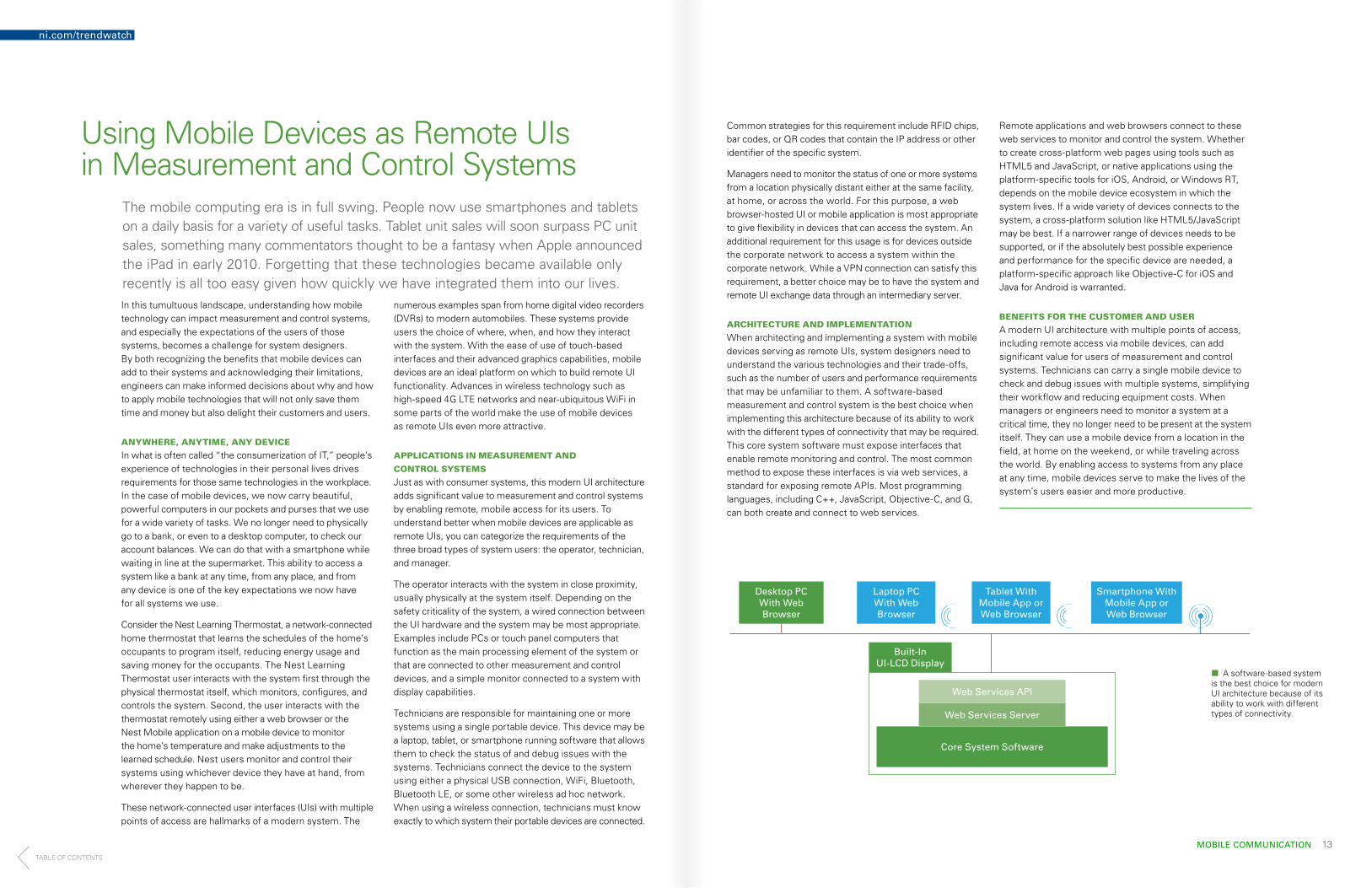
¢¢ A software-based system is the best choice for modern UI architecture because of its ability to work with different types of connectivity.
The mobile computing era is in full swing. People now use smartphones and tablets on a daily basis for a variety of useful tasks. Tablet unit sales will soon surpass PC unit sales, something many commentators thought to be a fantasy when Apple announced the iPad in early 2010. Forgetting that these technologies became available only recently is all too easy given how quickly we have integrated them into our lives.In this tumultuous landscape, understanding how mobile technology can impact measurement and control systems, and especially the expectations of the users of those systems, becomes a challenge for system designers. By both recognizing the benefits that mobile devices can add to their systems and acknowledging their limitations, engineers can make informed decisions about why and how to apply mobile technologies that will not only save them time and money but also delight their customers and users.
ANYWHERE, ANYTIME, ANY DEVICE
In what is often called “the consumerization of IT,” people’s experience of technologies in their personal lives drives requirements for those same technologies in the workplace. In the case of mobile devices, we now carry beautiful, powerful computers in our pockets and purses that we use for a wide variety of tasks. We no longer need to physically go to a bank, or even to a desktop computer, to check our account balances. We can do that with a smartphone while waiting in line at the supermarket. This ability to access a system like a bank at any time, from any place, and from any device is one of the key expectations we now have for all systems we use.
Consider the Nest Learning Thermostat, a network-connected home thermostat that learns the schedules of the home’s occupants to program itself, reducing energy usage and saving money for the occupants. The Nest Learning Thermostat user interacts with the system first through the physical thermostat itself, which monitors, configures, and controls the system. Second, the user interacts with the thermostat remotely using either a web browser or the Nest Mobile application on a mobile device to monitor the home’s temperature and make adjustments to the learned schedule. Nest users monitor and control their systems using whichever device they have at hand, from wherever they happen to be.
These network-connected user interfaces (UIs) with multiple points of access are hallmarks of a modern system. The
numerous examples span from home digital video recorders (DVRs) to modern automobiles. These systems provide users the choice of where, when, and how they interact with the system. With the ease of use of touch-based interfaces and their advanced graphics capabilities, mobile devices are an ideal platform on which to build remote UI functionality. Advances in wireless technology such as high-speed 4G LTE networks and near-ubiquitous WiFi in some parts of the world make the use of mobile devices as remote UIs even more attractive.
APPLICATIONS IN MEASUREMENT AND
CONTROL SYSTEMS
Just as with consumer systems, this modern UI architecture adds significant value to measurement and control systems by enabling remote, mobile access for its users. To understand better when mobile devices are applicable as remote UIs, you can categorize the requirements of the three broad types of system users: the operator, technician, and manager.
The operator interacts with the system in close proximity, usually physically at the system itself. Depending on the safety criticality of the system, a wired connection between the UI hardware and the system may be most appropriate. Examples include PCs or touch panel computers that function as the main processing element of the system or that are connected to other measurement and control devices, and a simple monitor connected to a system with display capabilities.
Technicians are responsible for maintaining one or more systems using a single portable device. This device may be a laptop, tablet, or smartphone running software that allows them to check the status of and debug issues with the systems. Technicians connect the device to the system using either a physical USB connection, WiFi, Bluetooth, Bluetooth LE, or some other wireless ad hoc network. When using a wireless connection, technicians must know exactly to which system their portable devices are connected.
Common strategies for this requirement include RFID chips, bar codes, or QR codes that contain the IP address or other identifier of the specific system.
Managers need to monitor the status of one or more systems from a location physically distant either at the same facility, at home, or across the world. For this purpose, a web browser-hosted UI or mobile application is most appropriate to give flexibility in devices that can access the system. An additional requirement for this usage is for devices outside the corporate network to access a system within the corporate network. While a VPN connection can satisfy this requirement, a better choice may be to have the system and remote UI exchange data through an intermediary server.
ARCHITECTURE AND IMPLEMENTATION
When architecting and implementing a system with mobile devices serving as remote UIs, system designers need to understand the various technologies and their trade-offs, such as the number of users and performance requirements that may be unfamiliar to them. A software-based measurement and control system is the best choice when implementing this architecture because of its ability to work with the different types of connectivity that may be required. This core system software must expose interfaces that enable remote monitoring and control. The most common method to expose these interfaces is via web services, a standard for exposing remote APIs. Most programming languages, including C++, JavaScript, Objective-C, and G, can both create and connect to web services.
Remote applications and web browsers connect to these web services to monitor and control the system. Whether to create cross-platform web pages using tools such as HTML5 and JavaScript, or native applications using the platform-specific tools for iOS, Android, or Windows RT, depends on the mobile device ecosystem in which the system lives. If a wide variety of devices connects to the system, a cross-platform solution like HTML5/JavaScript may be best. If a narrower range of devices needs to be supported, or if the absolutely best possible experience and performance for the specific device are needed, a platform-specific approach like Objective-C for iOS and Java for Android is warranted.
BENEFITS FOR THE CUSTOMER AND USER
A modern UI architecture with multiple points of access, including remote access via mobile devices, can add significant value for users of measurement and control systems. Technicians can carry a single mobile device to check and debug issues with multiple systems, simplifying their workflow and reducing equipment costs. When managers or engineers need to monitor a system at a critical time, they no longer need to be present at the system itself. They can use a mobile device from a location in the field, at home on the weekend, or while traveling across the world. By enabling access to systems from any place at any time, mobile devices serve to make the lives of the system’s users easier and more productive.
ni.com/trendwatch
TABLE OF CONTENTS

ni.com/trendwatch
FUTURE OF STEM 15
Making Waves in Technology EducationThe days of being responsible for a single engineering or scientific domain are ending. The days of designing complete, integrated systems are upon us. Look at the consumer products making an impact on everyday life. Today’s automobiles include more than 70 embedded controllers to tune an engine’s performance on the fly. Some of these automobiles can place and receive phone calls, provide navigation, and drive and park on their own. Basic cellphones are a thing of the past—smartphones are in everyone’s pocket, have millions of applications, and wirelessly connect to a growing array of devices. Using smartphone apps, you can even control home security and lighting while away on vacation. These examples are only the tip of the iceberg. So what can you learn from today’s innovations to help shape science, technology, engineering, and math (STEM) education and prepare the engineers of tomorrow to solve grand challenges?
First, consider the components of today’s technology innovations to understand what is driving them:
Processing Power Is Abundant—With modern technology like multicore processors and FPGAs, systems can process signals and perform arithmetic in nanoseconds. And history has proven that processors become cheaper and faster every year, allowing for their use in more products than ever before.
Sensors Are Smarter—Taking a physical phenomenon and converting it to an electrical signal has opened doors for millions of applications. Sensors make it possible for electronic systems to hear, see, touch, and act, resulting in automation for countless decisions.
The Software Is the Instrument—Hardware is not merely the physical device anymore. Software drives the functionality of hardware and can transform it into any device you can imagine. The smartphone is a technological feat, considering all the power packed into the palm-sized device, but we all know that the apps are what make it truly revolutionary.
The World Is Connected Wirelessly—Access to the Internet is now ubiquitous in most developed regions and has the power to connect people and devices regardless of their location. The cumbersome wires that have long been the bane of electrical engineers have recently disappeared due to advancements in wireless communication protocols and lower power requirements.
Though all of these components are revolutionary on their own, bringing them together has sparked even greater innovation. Combining the elements of communication,
computation, and control into a single system has resulted in the rise of cyber-physical systems. These cyber-physical systems feature many of today’s innovations and require new skills from graduating engineers who are being asked to begin innovating as soon as they enter the workforce.
EVOLUTION THROUGH INNOVATION
Throughout history, changing educational curricula has required the forward-thinking insight of a person, or a small group of people, to identify a need in our society. These pioneers then researched and tested their hypotheses to validate them. If their theories held true, their techniques and strategies were shared with others who replicated them on a greater scale. But these theories and concepts weren’t shared in a chat room or on a message board. Faculty members in colleges and universities integrated these innovations into their classrooms. These innovations in industry and research inspired the skills required for students to graduate and enter the workforce as the engineers and scientists society needed to build bridges that did not collapse and airplanes that could travel across the Atlantic Ocean on a single tank of fuel.
An example of this can be found in the genesis of electrical engineering as a dedicated field of study, separated from the study of physics, in the 19th century. But this was not just a singular occurrence. In recent decades the trend has repeated itself as biomedical engineering became an official field of study to fill the industry demand of needing engineers with cross-disciplinary knowledge of electrical and mechanical engineering with an understanding of anatomy and medical practices. Other fields such as green engineering, environmental engineering, and power electronics have grown in popularity over the past decade as the world has shifted away from fossil fuel dependency and looked for other ways to harvest and distribute power.
As current students progress through their educations and prepare for industry, cross-disciplinary and design courses have become increasingly important. Ohm’s law and the laws of thermodynamics are not going to disappear, but learning to work in teams and assemble larger, more complex systems comprised of cyber and physical elements is proving to be of greater importance. Students must be able to meet the exciting challenges of applying theory and “doing engineering” to produce results within a single semester, much like they will need to do in industry upon graduation
NEW LESSONS PRODUCE NEW RESULTS
The tools students use in their studies must enable their education in the fundamentals of engineering and science, so they can combine these fundamentals into more complex systems and be relevant to industry to avoid any redundant or wasted knowledge. Some colleges and universities around the world have already begun adapting their curricula to prepare their students to be the cyber-physical system designers that industry now demands. Mechanical engineering students at the University of Leeds in the United Kingdom start with basic control algorithms and then finish with fully autonomous vehicles. The University
of California, San Diego has begun a master‘s program that incorporates hands-on model-based design of wireless, embedded, and cyber-physical systems. And students at Olin College recently designed a fully autonomous sailboat using the latest commercial technology with plans to sail across the Atlantic Ocean.
Though focusing curricula on system design requires adjustments to classroom tools and educational goals, professors have found that many incoming students handle these adjustments because they began practicing system design concepts at an early age. In-school robotics clubs and programs like FIRST (For Inspiration and Recognition of Science and Technology) and the WRO (World Robot Olympiad) expose students to the fundamentals of system design in primary school and secondary school. These young engineers construct robots, acquire data from sensors, automate decisions, and control actuators. This is encouraging because these students are preparing to be the well-rounded, multidisciplined, cyber-physical system designers of tomorrow. Given the proper tools, projects, and guidance, they will continue to build these skills as they progress through their educations.
1844Samuel Morse Sends First Long Distance Electric Telegraph
1866Werner Von Siemens Develops First Industrial Generator
1902MIT Forms Electrical Engineering Department
1883Cornell University Offers First Electrical Engineering Courses
1752Ben Franklin Flies Kite With Key Attached During Lightning
1819Ørsted and Ampère Recognize the Phenomena of Electromagnetism
1827Ohm Publishes Die galvanische Kette, mathematisch bearbeitet and Ohm’s Law
1882Thomas Edison Opens First DC Electric Utility Company
TU Darmstadt Founds the World’s First Chair of Electrical Engineering
Scientifi c Discovery Commercial Innovation Education Adoption
¢¢ Throughout the late 19th and early 20th centuries, industrial innovation led to the formation of the field of electrical engineering, which was once categorized within the field of physics.
TABLE OF CONTENTS

©2014 National Instruments. All rights reserved. Big Analog Data, LabVIEW, National Instruments, NI, ni.com, and The Software is the Instrument are trademarks of National Instruments. Other product and company names listed are trademarks or trade names of their respective companies. MATLAB® is a registered trademark of The MathWorks, Inc. 351019A-01 14517
� ni.com/trendwatch