NI cRIO-9030 Getting Started Guide - National Instruments · 2018-10-18 · GETTING STARTED GUIDE...
18
GETTING STARTED GUIDE NI cRIO-9030 Embedded CompactRIO Controller with Real-Time Processor and Reconfigurable FPGA This document describes how to begin using the National Instruments cRIO-9030. Safety Guidelines Caution Do not operate the cRIO-9030 in a manner not specified in this document. Product misuse can result in a hazard. You can compromise the safety protection built into the product if the product is damaged in any way. If the product is damaged, return it to NI for repair. Safety Guidelines for Hazardous Locations The cRIO-9030 is suitable for use in Class I, Division 2, Groups A, B, C, D, T4 hazardous locations; Class I, Zone 2, AEx nA IIC T4 and Ex nA IIC T4 hazardous locations; and nonhazardous locations only. Follow these guidelines if you are installing the cRIO-9030 in a potentially explosive environment. Not following these guidelines may result in serious injury or death.
Transcript of NI cRIO-9030 Getting Started Guide - National Instruments · 2018-10-18 · GETTING STARTED GUIDE...

GETTING STARTED GUIDE
NI cRIO-9030Embedded CompactRIO Controller with Real-Time Processor andReconfigurable FPGA
This document describes how to begin using the National Instruments cRIO-9030.
Safety GuidelinesCaution Do not operate the cRIO-9030 in a manner not specified in this document.Product misuse can result in a hazard. You can compromise the safety protectionbuilt into the product if the product is damaged in any way. If the product isdamaged, return it to NI for repair.
Safety Guidelines for Hazardous LocationsThe cRIO-9030 is suitable for use in Class I, Division 2, Groups A, B, C, D, T4 hazardouslocations; Class I, Zone 2, AEx nA IIC T4 and Ex nA IIC T4 hazardous locations; andnonhazardous locations only. Follow these guidelines if you are installing the cRIO-9030 in apotentially explosive environment. Not following these guidelines may result in serious injuryor death.

Caution Do not disconnect the power supply wires and connectors from thecontroller unless power has been switched off.
Caution Do not disconnect I/O-side wires or connectors unless power has beenswitched off or the area is known to be nonhazardous.
Caution Do not remove modules unless power has been switched off or the area isknown to be nonhazardous.
Caution Substitution of components may impair suitability for Class I, Division 2.
Caution For Division 2 and Zone 2 applications, install the system in an enclosurerated to at least IP54 as defined by IEC/EN 60079-15.
Caution Do not insert or remove SD cards unless power has been switched off orthe area is known to be nonhazardous.
Caution The USB host ports, USB device port, mini DisplayPort, and SD card slotrequire the retention accessories listed in the following table for hazardous locations.All cables must be used in a conduit or cable gland to wire to a nonhazardouslocation. Do not disconnect a cable unless the cRIO-9030 is powered off or the areais known to be nonhazardous.
Table 1. Hazardous Location Retention Accessories
Port Required Accessory Part Number
USB Host Port NI Industrial USB Extender Cable 152166-xx
USB Device Port NI Locking USB Cable 157788-01
Mini DisplayPort Mini DisplayPort Cable Retention Bracket 156866-01
SD Card Slot SD Door Kit 783660-01
Special Conditions for Hazardous Locations Use in Europe andInternationallyThe cRIO-9030 has been evaluated as Ex nA IIC T4 Gc equipment under DEMKO CertificateNo. 12 ATEX 1202658X and is IECEx UL 14.0089X certified. Each device is marked II3G and is suitable for use in Zone 2 hazardous locations, in ambient temperatures of -20 °C ≤Ta ≤ 55 °C.
Caution You must make sure that transient disturbances do not exceed 140% ofthe rated voltage.
Caution The system shall only be used in an area of not more than PollutionDegree 2, as defined in IEC 60664-1.
2 | ni.com | NI cRIO-9030 Getting Started Guide
Caution The system shall be mounted in an ATEX/IECEx-certified enclosure witha minimum ingress protection rating of at least IP54 as defined in IEC/EN 60079-15.
Caution The enclosure must have a door or cover accessible only by the use of atool.
Electromagnetic Compatibility GuidelinesThis product was tested and complies with the regulatory requirements and limits forelectromagnetic compatibility (EMC) stated in the product specifications. These requirementsand limits provide reasonable protection against harmful interference when the product isoperated in the intended operational electromagnetic environment.
This product is intended for use in industrial locations. However, harmful interference mayoccur in some installations, when the product is connected to a peripheral device or test object,or if the product is used in residential or commercial areas. To minimize interference withradio and television reception and prevent unacceptable performance degradation, install anduse this product in strict accordance with the instructions in the product documentation.
Furthermore, any changes or modifications to the product not expressly approved by NationalInstruments could void your authority to operate it under your local regulatory rules.
Caution To ensure the specified EMC performance, operate this product only withshielded cables and accessories. The DC power input cables may be unshielded.
Caution To ensure the specified EMC performance, you must use an isolated cablewith the RS-485 serial port, such as NI part number 184428-01.
Caution To ensure the specified EMC performance, the length of any cableconnected to the video and V2 ports must be no longer than 3 m (10 ft). The lengthof any cable connected to the RS-232 and RS-485 ports must be no longer than30 m (100 ft). The length of any cable connected to the USB host ports must be nolonger than 5 m (16 ft).
Caution The USB device port is intended only for use in device configuration,application deployment, debug, and maintenance.
Caution To ensure the specified EMC performance, product installation requireseither special considerations or user-installed, add-on devices. Refer to the followingsections for more information.
Related InformationConnecting the cRIO-9030 to Ground on page 7Connecting the cRIO-9030 to Power on page 8
NI cRIO-9030 Getting Started Guide | © National Instruments | 3

Special Conditions for Marine ApplicationsSome products are Lloyd’s Register (LR) Type Approved for marine (shipboard) applications.To verify Lloyd’s Register certification for a product, visit ni.com/certification and search forthe LR certificate, or look for the Lloyd’s Register mark on the product.
Caution In order to meet the EMC requirements for marine applications, install theproduct in a shielded enclosure with shielded and/or filtered power and input/outputports. In addition, take precautions when designing, selecting, and installingmeasurement probes and cables to ensure that the desired EMC performance isattained.
Preparing the EnvironmentEnsure that the environment in which you are using the cRIO-9030 meets the followingspecifications.
Operating temperature(IEC 60068-2-1, IEC 60068-2-2)
-20 °C to 55 °C
Operating humidity (IEC 60068-2-56) 10% RH to 90% RH, noncondensing
Pollution degree 2
Maximum altitude 5,000 m
Indoor use only.
Note Refer to the device specifications on ni.com/manuals for completespecifications.
Unpacking the KitCaution To prevent electrostatic discharge (ESD) from damaging the device,ground yourself using a grounding strap or by holding a grounded object, such asyour computer chassis.
1. Touch the antistatic package to a metal part of the computer chassis.2. Remove the device from the package and inspect the device for loose components or any
other sign of damage.
Caution Never touch the exposed pins of connectors.
Note Do not install a device if it appears damaged in any way.
3. Unpack any other items and documentation from the kit.
Store the device in the antistatic package when the device is not in use.
4 | ni.com | NI cRIO-9030 Getting Started Guide

Verifying the Kit ContentsVerify that the following items are included in the cRIO-9030 kit.
Figure 1. cRIO-9030 Kit Contents
2 5431
1. cRIO Device with Power Connector and SD CardSlot Cover
2. USB A-to-B Cable3. Ferrite (x2)
4. NI-RIO Device Drivers Media5. Getting Started Guide
Installing Software on the Host ComputerBefore using the cRIO-9030, you must install the following application software and devicedrivers on the host computer in this order:1. LabVIEW 2014 or later2. LabVIEW Real-Time Module 2014 or later3. LabVIEW FPGA Module 2014 or later1
4. NI-RIO Device Drivers August 2014 or later
For minimum software support information, visit ni.com/info and enter the Info Codeswsupport.
Installing C Series ModulesComplete the following steps to install a C Series module.
1 LabVIEW FPGA Module is not required when using Scan Interface mode. To program the user-accessible FPGA on the cRIO-9030, LabVIEW FPGA Module is required.
NI cRIO-9030 Getting Started Guide | © National Instruments | 5

3
2
2
1
1. Verify that power is not connected to the I/O connector(s) on the C Series module. If thesystem is in a nonhazardous location, the cRIO-9030 can be powered on when you installmodules.
2. Press the latches on the C Series module.3. Align the C Series module with a slot and seat it in the slot until the latches lock in place.
Removing C Series ModulesVerify that power is not connected to the I/O connector(s) on the C Series module before youremove a module from the cRIO-9030. If the system is in a nonhazardous location, thecRIO-9030 can be powered on when you remove modules.
Connecting the cRIO-9030The cRIO-9030 has the following connectors, LEDs, and buttons.
6 | ni.com | NI cRIO-9030 Getting Started Guide

Figure 2. cRIO-9030 Front Panel
1 2 3
4
5
6
8911
14
13
12
10 7
1. LEDs2. Ethernet Ports3. Power Connector4. SD LEDs5. SD Card Removable Storage6. Ground Screw7. USER1 Button
8. RS-232 Serial Port9. RS-485/422 (DTE) Serial Port10. USB Host Ports11. Mini DisplayPort12. Cable Retention Mounts13. USB Device Port14. Power and Reset Buttons
Connecting the cRIO-9030 to GroundYou must connect the cRIO-9030 grounding terminal to the grounding electrode system of thefacility.
What to Use
• Ring lug• Wire, 1.3 mm2 (16 AWG) or larger• Screwdriver, Phillips #2
What to Do
Complete the following steps to ground the cRIO-9030.1. Attach the ring lug to the wire.2. Remove the grounding screw from the grounding terminal on the cRIO-9030.3. Attach the ring lug to the grounding terminal.4. Tighten the grounding screw to 0.5 N · m (4.4 lb · in.) of torque.5. Attach the other end of the wire to the grounding electrode system of your facility using a
method that is appropriate for your application.
NI cRIO-9030 Getting Started Guide | © National Instruments | 7

Caution If you use shielded cabling to connect to a C Series module with a plasticconnector, you must attach the cable shield to the chassis grounding terminal using1.3 mm2 (16 AWG) or larger wire. Attach a ring lug to the wire and attach the wireto the chassis grounding terminal. Solder the other end of the wire to the cableshield. Use shorter wire for better EMC performance.
For more information about ground connections, visit ni.com/info and enter the Info Codeemcground.
Connecting the cRIO-9030 to PowerThe cRIO-9030 requires a 9 V to 30 V external power supply. The cRIO-9030 filters andregulates the supplied power and provides power for the C Series modules. The cRIO-9030has a primary power input, V1, and a secondary power input, V2.
The POWER LED on the cRIO-9030 indicates which power input is in use, as shown in thefollowing table.
Table 2. POWER LED Indicators
LED Color LED Pattern Indication
Green Solid The cRIO-9030 is powered from the V1 input.
Yellow Solid The cRIO-9030 is powered from the V2 input.
— Off The cRIO-9030 is powered off.
Caution Do not connect V2 to a DC mains supply or to any supply that requires aconnecting cable longer than 3 m (10 ft). A DC mains supply is a local DCelectricity supply network in the infrastructure of a site or building.
What to Use
• Ferrite• Screwdriver, 2.54 mm (0.10 in.) flathead• Primary power supply, 9 V to 30 V, 40 W minimum• (Optional) Secondary power supply, 9 V to 30 V, 40 W minimum
NI recommends the power supplies listed in the following table for the cRIO-9030.
8 | ni.com | NI cRIO-9030 Getting Started Guide
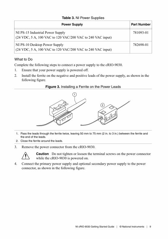
Table 3. NI Power Supplies
Power Supply Part Number
NI PS-15 Industrial Power Supply(24 VDC, 5 A, 100 VAC to 120 VAC/200 VAC to 240 VAC input)
781093-01
NI PS-10 Desktop Power Supply(24 VDC, 5 A, 100 VAC to 120 VAC/200 VAC to 240 VAC input)
782698-01
What to Do
Complete the following steps to connect a power supply to the cRIO-9030.1. Ensure that your power supply is powered off.2. Install the ferrite on the negative and positive leads of the power supply, as shown in the
following figure.
Figure 3. Installing a Ferrite on the Power Leads
2
1
1. Pass the leads through the ferrite twice, leaving 50 mm to 75 mm (2 in. to 3 in.) between the ferrite andthe end of the leads.
2. Close the ferrite around the leads.
3. Remove the power connector from the cRIO-9030.
Caution Do not tighten or loosen the terminal screws on the power connectorwhile the cRIO-9030 is powered on.
4. Connect the primary power supply and optional secondary power supply to the powerconnector, as shown in the following figure.
NI cRIO-9030 Getting Started Guide | © National Instruments | 9
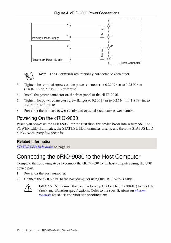
Figure 4. cRIO-9030 Power Connections
Power Connector
V2
C
C
V1
Primary Power Supply
+
–
–
+
Secondary Power Supply
Fer
rite
Fer
rite
Note The C terminals are internally connected to each other.
5. Tighten the terminal screws on the power connector to 0.20 N · m to 0.25 N · m(1.8 lb · in. to 2.2 lb · in.) of torque.
6. Install the power connector on the front panel of the cRIO-9030.7. Tighten the power connector screw flanges to 0.20 N · m to 0.25 N · m (1.8 lb · in. to
2.2 lb · in.) of torque.8. Power on the primary power supply and optional secondary power supply.
Powering On the cRIO-9030When you power on the cRIO-9030 for the first time, the device boots into safe mode. ThePOWER LED illuminates, the STATUS LED illuminates briefly, and then the STATUS LEDblinks twice every few seconds.
Related InformationSTATUS LED Indicators on page 14
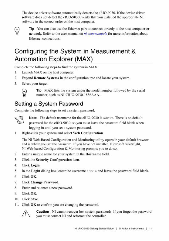
Connecting the cRIO-9030 to the Host ComputerComplete the following steps to connect the cRIO-9030 to the host computer using the USBdevice port.1. Power on the host computer.2. Connect the cRIO-9030 to the host computer using the USB A-to-B cable.
Caution NI requires the use of a locking USB cable (157788-01) to meet the shock and vibration specifications. Refer to the specifications on ni.com/manuals for shock and vibration specifications.
10 | ni.com | NI cRIO-9030 Getting Started Guide
The device driver software automatically detects the cRIO-9030. If the device driversoftware does not detect the cRIO-9030, verify that you installed the appropriate NIsoftware in the correct order on the host computer.
Tip You can also use the Ethernet port to connect directly to the host computer ornetwork. Refer to the user manual on ni.com/manuals for more information aboutEthernet connections.
Configuring the System in Measurement &Automation Explorer (MAX)Complete the following steps to find the system in MAX.1. Launch MAX on the host computer.2. Expand Remote Systems in the configuration tree and locate your system.3. Select your target.
Tip MAX lists the system under the model number followed by the serialnumber, such as NI-CRIO-9030-1856AAA.
Setting a System PasswordComplete the following steps to set a system password.
Note The default username for the cRIO-9030 is admin. There is no defaultpassword for the cRIO-9030, so you must leave the password field blank whenlogging in until you set a system password.
1. Right-click your system and select Web Configuration.
The NI Web-Based Configuration and Monitoring utility opens in your default browserand is where you set the password. If you have not installed Microsoft Silverlight,NI Web-based Configuration & Monitoring prompts you to do so.
2. Enter a unique name for your system in the Hostname field.3. Click the Security Configuration icon.4. Click Login.5. In the Login dialog box, enter the username admin and leave the password field blank.6. Click OK.7. Click Change Password.8. Enter and re-enter a new password.9. Click OK.10. Click Save.11. Click OK to confirm you are changing the password.
Caution NI cannot recover lost system passwords. If you forget the password,you must contact NI and reformat the controller.
NI cRIO-9030 Getting Started Guide | © National Instruments | 11

Installing Software on the cRIO-9030Complete the following steps to install software on the cRIO-9030.1. In MAX, expand your system under Remote Systems.2. Right-click Software.3. Select Add/Remove Software to launch the LabVIEW Real-Time Software Wizard.
Tip You must log in if you set a system password.
4. Select the recommended software set for your LabVIEW and NI-RIO Device Driversversions.
5. Click Next.6. Select NI Scan Engine from the software add-ons.
Select any additional software to install. If you plan on using the cRIO-9030 with theLabVIEW FPGA Module, you can click Next. Click NI Scan Engine if you plan onusing the cRIO-9030 without the LabVIEW FPGA Module.
Tip You can use this wizard at anytime to install additional software.
7. Click Next.8. Verify that the summary of software to install is correct.9. Click Next to start the installation.10. Click Finish when the installation is complete.
Troubleshooting the cRIO-9030
The cRIO-9030 is Not Communicating with theNetwork• Ensure that the USB connections between the cRIO-9030 and the host computer and the
Ethernet connections between the host computer and the router are secure.• Configure the IP and other network settings by completing the following steps.
1. Use a USB A-to-B cable to connect the cRIO-9030 USB device port to a hostcomputer. The USB driver creates a virtual network interface card and assigns an IPaddress to the cRIO-9030 in the format of 172.22.11.x.
2. In MAX, expand your system under Remote Systems.
12 | ni.com | NI cRIO-9030 Getting Started Guide
3. Select the Network Settings tab to configure the IP and other network settings.4. (Optional) Use the RJ-45 Ethernet port 1 to reconnect the cRIO-9030 to the host
computer. The cRIO-9030 attempts to initiate a DHCP network connection atpowerup.
Note If the cRIO-9030 cannot obtain an IP address, it connects to thenetwork with a link-local IP address with the form 169.254.x.x. The hostcomputer communicates with the cRIO-9030 over a standard Ethernetconnection.
• Ensure that you have the correct version of NI-RIO Device Drivers installed on the hostcomputer. Visit ni.com/info and enter the Info Code swsupport for the minimumsupported versions of LabVIEW and NI-RIO Device Drivers.
Tip If you have recently upgraded LabVIEW, you must reinstall NI-RIODevice Drivers.
• Ensure that the NI USBLAN adapter is recognized in the Device Manager. OnWindows 7, select Start»Control Panel»Device Manager»Network adapters»NationalInstruments»USBLAN adapter. If the USBLAN adapter is not recognized, you mustreinstall NI-RIO Device Drivers.
• Temporarily disable any network firewalls or other security software.
Verify the System IP Configuration1. Put the cRIO-9030 in safe mode and enable the RS-232 serial port by holding the RESET
button down for 5 seconds.
The STATUS LED starts blinking three times every few seconds.2. Use the RS-232 serial port terminal to read the IP address, or connect a monitor to the
mini DisplayPort to view the IP address.
Note Refer to the user manual on ni.com/manuals for more information aboutserial port configuration.
3. Set a new DHCP connection by holding the RESET button down for 5 seconds. TheSTATUS LED repeats the same behavior from Step 1.
If the cRIO-9030 fails to set a new DHCP address, it assigns itself a link-local IP address.If the DHCP connection is successful and appropriate for your application, skip to Step 6.
4. In MAX, expand your system under Remote Systems.5. Select the Network Settings tab to configure the IP and other network settings.6. Reboot the cRIO-9030 by pressing the RESET button.
Configure the Windows Firewall• Add an exception for MAX to your network firewall or other security software by
completing the following steps:1. On Windows 7, select Start»Control Panel»System and Security»Windows
Firewall»Allow a program through Windows Firewall.2. Click Allow another program.3. Select Measurement & Automation.
NI cRIO-9030 Getting Started Guide | © National Instruments | 13

4. Click Add.5. Click OK.
• Ensure that UDP port 44525 is open to communication on the host computer. If you areusing an intelligent switch on the network, ensure that it is not disabling UDP port 44525.
System ResetThe following figure shows the reset behavior of the cRIO-9030.
Figure 5. Reset Button Behavior
Press and hold RESET button for ≥ 5 s
Press and hold RESET button for < 5 sRun Mode
Safe ModePress and hold RESET button for < 5 s
Press and hold RESET button for ≥ 5 s
Press and hold RESET button for ≥ 5 s
Press and hold RESET button for < 5 s
• Console Out enabled• Network settings reset• RT Startup App disabled• FPGA Startup App disabled
• Console Out enabled• RT Startup App disabled• FPGA Startup App disabled
Safe Mode
STATUS LED IndicatorsThe following table describes the STATUS LED indicators.
14 | ni.com | NI cRIO-9030 Getting Started Guide

Table 4. STATUS LED Indicators
LEDColor
LED Pattern Indication
Yellow Blinks twice andpauses
The cRIO-9030 is in safe mode. Software is not installed,which is the factory default state, or software has beenimproperly installed on the cRIO-9030.
An error can occur when an attempt to upgrade the softwareis interrupted. Reinstall software on the cRIO-9030. Referto the Measurement & Automation Explorer (MAX) Help forinformation about installing software on the cRIO-9030.
Blinks three timesand pauses
The cRIO-9030 is in user-directed safe mode, or thecRIO-9030 is in install mode to indicate that software iscurrently being installed.
This pattern may also indicate that the user has forced thecRIO-9030 to boot into safe mode by pressing the resetbutton for longer than five seconds or by enabling safemode in MAX. Refer to the Measurement & AutomationExplorer (MAX) Help for information about safe mode.
Blinks four timesand pauses
The cRIO-9030 is in safe mode. The software has crashedtwice without rebooting or cycling power between crashes.
Continuouslyblinks
The cRIO-9030 has not booted into NI Linux Real-Time.The cRIO-9030 either booted into an unsupported operatingsystem, was interrupted during the boot process, or detectedan unrecoverable software error.
On momentarily The cRIO-9030 is booting. No action required.
Red Continuouslyblinks
This indicates a hardware error. An internal power supplyhas failed. Check front-panel I/O and C Series moduleconnections for shorts. Remove any shorts and cycle powerthe cRIO-9030. If the problem persists, contact NI.
— Off The cRIO-9030 is in run mode. Software is installed and theoperating system is running.
NI cRIO-9030 Getting Started Guide | © National Instruments | 15

Where to Go Next
APPLICATION
SUPPORT
Servicesni.com/services
NI Communityni.com/community
NI CompactRIODeveloper’s Guide
Software Supportni.com/info swsupport
Supportni.com/support
SOFTWARE
NI cRIO-9030 Specifications Configuring a Projectni.com/manuals NI-RIO Help
ni.com/compactriodevguide
CompactRIO SampleProjects
LabVIEW Create Project
HARDWARE
NI cRIO-9030 User Manualni.com/manuals
C Series GettingStarted Guidesni.com/manuals
Learn LabVIEW Basicsni.com/gettingstarted
CompactRIO ExamplesNI Example Finder
Worldwide Support and ServicesThe National Instruments website is your complete resource for technical support. At ni.com/support, you have access to everything from troubleshooting and application developmentself-help resources to email and phone assistance from NI Application Engineers.
Visit ni.com/services for NI Factory Installation Services, repairs, extended warranty, andother services.
Visit ni.com/register to register your National Instruments product. Product registrationfacilitates technical support and ensures that you receive important information updates fromNI.
A Declaration of Conformity (DoC) is our claim of compliance with the Council of theEuropean Communities using the manufacturer’s declaration of conformity. This systemaffords the user protection for electromagnetic compatibility (EMC) and product safety. Youcan obtain the DoC for your product by visiting ni.com/certification. If your product supportscalibration, you can obtain the calibration certificate for your product at ni.com/calibration.
16 | ni.com | NI cRIO-9030 Getting Started Guide

National Instruments corporate headquarters is located at 11500 North Mopac Expressway,Austin, Texas, 78759-3504. National Instruments also has offices located around the world.For telephone support in the United States, create your service request at ni.com/support ordial 1 866 ASK MYNI (275 6964). For telephone support outside the United States, visit theWorldwide Offices section of ni.com/niglobal to access the branch office websites, whichprovide up-to-date contact information, support phone numbers, email addresses, and currentevents.
NI cRIO-9030 Getting Started Guide | © National Instruments | 17

Refer to the NI Trademarks and Logo Guidelines at ni.com/trademarks for information on National Instruments trademarks.Other product and company names mentioned herein are trademarks or trade names of their respective companies. For patentscovering National Instruments products/technology, refer to the appropriate location: Help»Patents in your software, thepatents.txt file on your media, or the National Instruments Patent Notice at ni.com/patents. You can find information aboutend-user license agreements (EULAs) and third-party legal notices in the readme file for your NI product. Refer to the ExportCompliance Information at ni.com/legal/export-compliance for the National Instruments global trade compliance policy andhow to obtain relevant HTS codes, ECCNs, and other import/export data. NI MAKES NO EXPRESS OR IMPLIED WARRANTIESAS TO THE ACCURACY OF THE INFORMATION CONTAINED HEREIN AND SHALL NOT BE LIABLE FOR ANY ERRORS.U.S. Government Customers: The data contained in this manual was developed at private expense and is subject to theapplicable limited rights and restricted data rights as set forth in FAR 52.227-14, DFAR 252.227-7014, and DFAR 252.227-7015.
© 2014—2015 National Instruments. All rights reserved.
376260B-01 Oct15