NGSLR Operations Manual - NASA · 2018. 12. 12. · NGSLR Operations Manual Preface Document...
80
NASA-NGSLR-OPS-Manual NGSLR Operations Manual Operating the Next Generation Satellite Laser Ranging System Jan McGarry, NASA/GSFC/694 Version 1.0 January 2014
Transcript of NGSLR Operations Manual - NASA · 2018. 12. 12. · NGSLR Operations Manual Preface Document...
NASA-NGSLR-OPS-Manual
NGSLR Operations Manual Operating the Next Generation Satellite Laser Ranging System
Jan McGarry, NASA/GSFC/694
Version 1.0
January 2014

NGSLR Operations Manual Preface
Document Number: P a g e | i NASA‐NGSLR‐OPS‐Manual (v1.0)
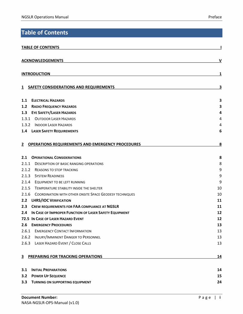
Table of Contents
TABLE OF CONTENTS I
ACKNOWLEDGEMENTS V
INTRODUCTION 1
1 SAFETY CONSIDERATIONS AND REQUIREMENTS 3
1.1 ELECTRICAL HAZARDS 3
1.2 RADIO FREQUENCY HAZARDS 3
1.3 EYE SAFETY/LASER HAZARDS 4
1.3.1 OUTDOOR LASER HAZARDS 4
1.3.2 INDOOR LASER HAZARDS 4
1.4 LASER SAFETY REQUIREMENTS 6
2 OPERATIONS REQUIREMENTS AND EMERGENCY PROCEDURES 8
2.1 OPERATIONAL CONSIDERATIONS 8
2.1.1 DESCRIPTION OF BASIC RANGING OPERATIONS 8
2.1.2 REASONS TO STOP TRACKING 9
2.1.3 SYSTEM READINESS 9
2.1.4 EQUIPMENT TO BE LEFT RUNNING 9
2.1.5 TEMPERATURE STABILITY INSIDE THE SHELTER 10
2.1.6 COORDINATION WITH OTHER ONSITE SPACE GEODESY TECHNIQUES 10
2.2 LHRS/IOC VERIFICATION 11
2.3 CREW REQUIREMENTS FOR FAA COMPLIANCE AT NGSLR 11
2.4 IN CASE OF IMPROPER FUNCTION OF LASER SAFETY EQUIPMENT 12
72.5 IN CASE OF LASER HAZARD EVENT 12
2.6 EMERGENCY PROCEDURES 13
2.6.1 EMERGENCY CONTACT INFORMATION 13
2.6.2 INJURY/IMMINENT DANGER TO PERSONNEL 13
2.6.3 LASER HAZARD EVENT / CLOSE CALLS 13
3 PREPARING FOR TRACKING OPERATIONS 14
3.1 INITIAL PREPARATIONS 14
3.2 POWER UP SEQUENCE 15
3.3 TURNING ON SUPPORTING EQUIPMENT 24
NGSLR Operations Manual Preface
Document Number: P a g e | i i NASA‐NGSLR‐OPS‐Manual (v1.0)
3.4 SAFETY PROTOCOL PRIOR TO TURNING ON THE SLR LASER 26
3.5 POWERING UP AND STARTING THE SLR LASER CONTROLLER 27
4 PERFORMING TRACKING OPERATIONS 29
4.1 GROUND CALIBRATION 29
4.2 SATELLITE TRACKING PROCESS 34
5 ROUTINE ALIGNMENT VERIFICATION 38
5.1 PERFORMING A STAR CALIBRATION 38
5.1.1 STAR CALIBRATION PROCEDURE 38
5.1.2 VERIFYING THE ADJUSTED POINTING BIASES PRODUCED BY THE STAR CALIBRATION 41
5.2 PERFORMING A STAR ASSESSMENT 44
6 PERFORMING MINICO AND STABILITY TESTS 45
6.1 PERFORMING A MINI‐COLLOCATION (MINICO) 45
6.2 PERFORMING A STABILITY TEST 49
7 SHUTTING DOWN THE SYSTEM 52
8 MOST COMMON ERRORS AND THEIR RESOLUTIONS 55
8.1 GETTING THE “MET” ERROR MESSAGE ON POP FOR LONGER THAN 10 MINUTES 55
8.2 NO IMAGE ON THE MONITOR FOR THE TELESCOPE CAMERA 55
8.3 MOUNT WON’T DRIVE / MOUNT DUMPS (ELEVATION > 90°) 56
8.4 THE LASER IS FIRING, BUT THE RAT DISPLAY SHOWS LASER FIRES ARE ZERO (F=0) 56
8.5 THE LASER WON’T FIRE 56
8.6 SYSTEM IS NOT GETTING RETURNS 60
8.6.1 NO RETURNS DURING GROUND CALIBRATIONS 60
8.6.2 LOW RETURN RATE DURING A GROUND CALIBRATION 60
8.6.3 NO RETURNS DURING SATELLITE TRACKING 61
8.7 THE SOFTWARE APPEARS TO HAVE CRASHED/IS NON‐RESPONSIVE 61
8.7.1 HOW TO DO A SOFT REBOOT ON POP 61
8.7.2 HOW TO DO A HARD REBOOT ON POP 62
8.7.3 HOW TO DO A SOFT REBOOT ON DAM 62
8.7.4 HOW TO DO A HARD REBOOT ON DAM 62
8.7.5 REMOUNTING THE DISK DRIVES ON POP AND DAM 63
8.7.6 HOW TO DO A SOFT REBOOT ON RAT 63
NGSLR Operations Manual Preface
Document Number: P a g e | i i i NASA‐NGSLR‐OPS‐Manual (v1.0)
8.7.7 HOW TO DO A HARD REBOOT ON RAT 63
8.7.8 HOW TO DO A SOFT REBOOT ON THE CAMERA COMPUTER 63
8.7.9 STARTING NFS AFTER TURNING ON/REBOOTING THE CAMERA COMPUTER 64
8.8 EVENT TIMER RESETS 65
8.8.1 EVENT TIMER CONTINUALLY RESETS 65
8.9 DOME WON’T OPEN OR CLOSE 66
APPENDIX A: ACRONYMS 67
APPENDIX B: NGSLR LASER RANGING LOG SHEET 68
APPENDIX C: ALERT STATUSES 69
APPENDIX D: MEASURING THE LASER POWER 70
APPENDIX E: MEASURING THE START DIODE VOLTAGE 72

NGSLR Operations Manual Preface
Document Number: P a g e | i v NASA‐NGSLR‐OPS‐Manual (v1.0)

NGSLR Operations Manual Preface
Document Number: P a g e | v NASA‐NGSLR‐OPS‐Manual (v1.0)
Acknowledgements
Removed (jlfm)
The development of NGSLR (formerly SLR2000) is funded through the Science Mission Directorate at NASA Headquarters.
This prototype is being developed by the Space Geodesy Project at Goddard Space Flight Center in cooperation with the
Laser Remote Sensing Laboratory, both part of the Solar System Exploration Division at Goddard.
NGSLR Operations Manual Preface
Document Number: P a g e | v i NASA‐NGSLR‐OPS‐Manual (v1.0)
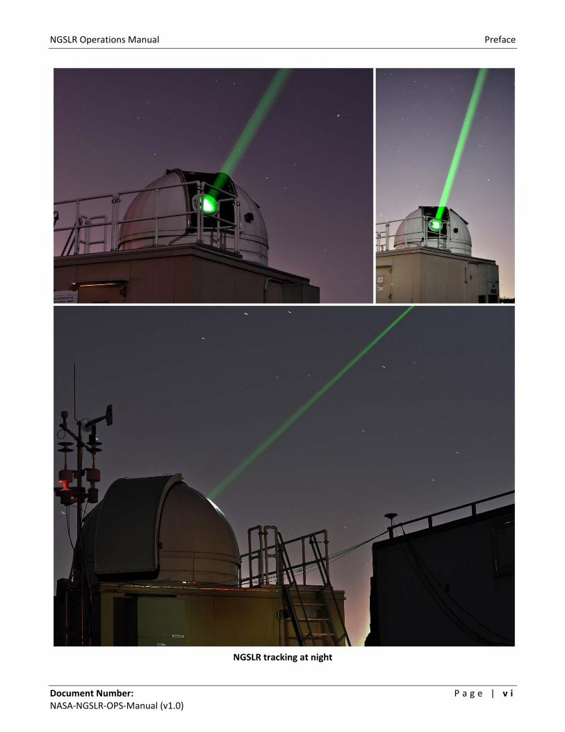
NGSLR tracking at night
NGSLR Operations Manual Table of Contents
Document Number: P a g e | 1 NASA‐NGSLR‐OPS‐Manual (v1.0)
Introduction
NASA’s Next Generation Satellite Laser Ranging (NGSLR) station is the prototype for NASA’s new Satellite Laser
Ranging (SLR) systems which will be deployed around the world in the coming decade. The prototype is located
at the Goddard Geophysical and Astronomical Observatory (GGAO), one of Goddard Space Flight Center’s secure
satellite facilities. NGSLR will be a semi‐ autonomous, single photon sensitive SLR station with an expected shot
to shot absolute range accuracy to LAGEOS of better than 1 centimeter and a normal point (time‐averaged)
range precision better than 1 millimeter.
When operational, the system will provide continuous, 24‐hour tracking coverage to an existing constellation of
approximately two dozen artificial satellites equipped with passive retroreflector arrays.
When deployed, these stations will be placed so that they have full access to both internet and phone
communication, with each system communicating regularly to an external facility (called Home). It is from here
that the station will obtain the satellite prediction data for the week, receive the tracking priority of satellites,
and send information on system health and performance. The Home Facility will send technicians periodically
and/or when the system needs repair. There is also expected to be a “caretaker” present most of the time at
each facility who will monitor the system and its operations.
NGSLR incorporates several key developments that are unique. For instance, existing NASA SLR stations require
operators to determine system viability, avoid direct contact of the laser beam with aircraft and ground
personnel, decide what objects to track, and interactively acquire and track those objects. However, the NGSLR
prototype will be semi‐automated, performing many of the above tasks automatically, including incorporating a
proven laser hazard reduction system (LHRS) to prevent the lasing of aircraft. In addition, NGSLR uses a low
power beam coupled with a high fire rate (2000 Hz), which has the dual benefit of allowing lower per pulse laser
energy levels, while increasing the number of possible returns per unit time, hence enhancing the normal point
precision. This technique creates a higher return rate per unit time, producing final data products that are the
same or better than those from legacy NASA SLR systems.
In addition to the normal 2‐way satellite laser ranging, the NGSLR system is capable of supporting other types of
laser ranging, including 1 and 2‐way asynchronous transponder ranging. Currently, the NGSLR prototype is
supporting 1‐way laser ranging to the Lunar Reconnaissance Orbiter (LRO), an uplink only range where NGSLR
records the laser fire times, and the spacecraft records the receive events. Analysts form ranges after the pass
by correctly associating fires with receive events. Further details on the LRO operations at NGSLR can be found
in: Laser Ranging to the Lunar Reconnaissance Orbiter (LRO) from NASA’s Next Generation Satellite Laser
Ranging Station (NGSLR), (NASA‐NGSLR‐OPS‐LRO).1
1 Further information can also be found in various papers and presentations including: Zuber, et al. (2010); Mao et al. (2010); Clarke et al. (2008); Mallama (2008); McGarry et al. (2008); McGarry & Zagwodzki (2009)

NGSLR Operations Manual Table of Contents
Document Number: P a g e | 2 NASA‐NGSLR‐OPS‐Manual (v1.0)
Overview of the Document
The purpose of this document is to provide instructions for operation of the NGSLR system.
This document will:
Describe the general configuration of the system
Lay out procedures for system power‐up and shutdown
Walk the operator through the normal sequence of events in tracking operations
Describe regularly performed calibration procedures
List the most common errors and their resolutions
All steps are listed in a numbered hierarchy, and begin with a summary of what is to be accomplished during each step, followed with a brief description of how to perform the task, along with any pertinent notes, warnings, and troubleshooting steps. The number and the summary description of each step match the steps listed in the operations checklist included in the appendix of this manual.
Example layout of procedures
The following symbols are used to identify certain types of hazards that exist within the system, along with procedures to mitigate risk. Compliance with the risk mitigation procedures identified in this document and NASA safety guidelines are mandatory.
Possible safety hazard or potential damage to equipment.
Possible laser safety hazard.
Possible electrical hazard.
1. Fill out the Operations Log – At the commencement of your shift, fill out the NGSLR Operations Log, as
shown in Appendix B. Make sure to keep this log sheet in a convenient place, as you will continue to
enter additional information with each pass / ground calibration that is performed.
2. Call the FAA – Inform the FAA of pending operations immediately after beginning the operations log.
a. Call the FAA. (See the posting in the shelter for the current number)
b. Say something similar to:
“This is Joe Smith at the Goddard Space Flight Center. I am calling to inform you that we are
commencing laser ranging operations.”
c. Write down the name of person spoken to along with the time in the Operations Log.
Summary of Step Detailed description
Step number

NGSLR Operations Manual Safety Considerations and Requirements
Document Number: P a g e | 3 NASA‐NGSLR‐OPS‐Manual (v1.0)
Possible radio frequency hazard.
1 Safety Considerations and Requirements
NGSLR is operated under the approval of the Occupational Safety and Health Division (OS&H) at the NASA
Goddard Space Flight Center and follows all guidelines and requirements established by that office and the
American National Standards Institute (ANSI). Because of the system’s proximity to multiple airports in the
Baltimore/Washington DC corridor, the Goddard Laser Safety Office has mandated additional requirements in
cooperation with the Federal Aviation Administration (FAA). These include notification of the National Capital
Regional Coordination Center (NCRCC) before and at the conclusion of scheduled laser operations for the week.
The NGSLR and LRO laser ranging programs use a combination of procedures, electromechanical systems, and
software to ensure SLR operations are safe. Both systems offer multiple verifications and redundancies to make
certain the operations of the system are properly conducted. In addition, all system users are required to
comply with the procedures and requirements listed in the NGSLR Safety Manual, the NGSLR Operations
Manual, the LRO Operations Manual and the NGSLR System Alignment, Focus and Maintenance Manual.
1.1 Electrical Hazards
Warning: Employees are not permitted to work on any electrical equipment when alone;
there is always a two‐person rule in effect. Where possible, the power supply should be
locked out and reduced to a zero energy state.
Instrumentation and equipment in the NGSLR shelter have no electrical hazard other than the standard 120V /
20A service that runs these devices.
1.2 Radio Frequency Hazards
Warning: Personnel are prohibited from being on the radar tower while the LHRS is in
operation, due to possible exposure to elevated levels of microwave radiation. The system
must be powered off and locked out prior to maintenance being performed.
Personnel on any adjacent structure should be a minimum of 10 feet away from the radiating antenna in order
to minimize exposure to RF energy. Though this distance is a minimum safe distance, exposure to all RF radiation
should be avoided whenever possible.

NGSLR Operations Manual Safety Considerations and Requirements
Document Number: P a g e | 4 NASA‐NGSLR‐OPS‐Manual (v1.0)
1.3 Eye Safety/Laser Hazards
Warning: The laser(s) can pose a serious visual hazard if proper precautions are not observed.
You must understand and follow the precautions listed in the NGSLR Safety Manual and in this
manual to ensure safe operation. Failure to follow these guidelines can result in severe eye
damage to anyone exposed to the beam. Only personnel who possess the Goddard Laser User
certification and are approved by the NGSLR project manager are allowed to operate the laser.
1.3.1 Outdoor Laser Hazards
The SLR and LRO lasers used in NGSLR are not eye‐safe and require the use of the Laser Hazard Reduction
System (LHRS), a radar‐based safety system that blocks the beam if it detects an aircraft approaching an
exclusion zone around the transmission path.
The NGSLR system is housed in a controlled area that limits direct access to the system. In addition, pressure
pads have been added to the stairway that provides access to the observatory dome. These pressure pads will
disable the laser should anyone attempt to access the roof during operations, thereby preventing exposure to
laser energy. Personnel are prohibited from remaining on the maintenance deck during operations due to the
possible risk of exposure to unsafe levels laser radiation. It is the responsibility of the operations staff to verify
that there are no personnel on the maintenance deck prior to commencing operations.
Protective eyewear that meets ANSI Z136 standards for the lasers used in the system are supplied in the NGSLR
shelter for use by engineering personnel when verifying the alignment of the beam. Eye protection will be worn
within this restricted area whenever the laser is operational. See the table below to select the appropriate
eyewear for each laser and power level.
Outdoor Requirements
Northrop Grumman (50 mJ max) >2.4 OD (Setting used for LRO Operations) Northrop Grumman (0.1 mJ setting) none required (Setting used for LRO Alignment) Photonics Industries (1.0 mJ setting) >1.2 OD (Setting used for SLR Operations) Photonics Industries (0.02 mJ setting) none required (Setting used for SLR Alignment)
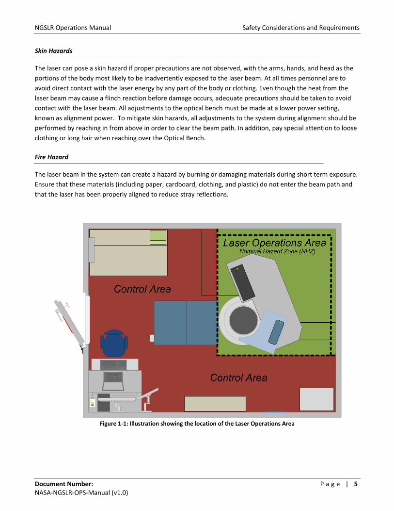
1.3.2 Indoor Laser Hazards
The SLR and LRO lasers operate in the Laser Operations Area (LOA) within NGSLR that protects the operator
from exposure during operation of the lasers (Figure 1‐1). Each laser is confined to a well defined beam path
around the optical bench, where considerable care has been taken to reduce backscatter and reflection off of
various surfaces. Any scattered light is collected by the black laser curtain that surrounds the LOA. Due to the
high peak power of the lasers on the optical bench, it is imperative that all personnel wear the appropriate
degree of eye protection to prevent accidental exposure to laser energy. As such, all personnel in the LOA during
operation of either laser are required to wear eye protection as listed below.
Indoor Requirements
Northrop Grumman (50 mJ setting) >5.6 OD (Setting used for LRO Operations) Northrop Grumman (0.1 mJ setting) >3.0 OD (Setting used for LRO Alignment) Photonics Industries (1.0 mJ setting) >4.7 OD (Setting used for SLR Operations) Photonics Industries (0.02 mJ setting) >3.0 OD (Setting used for SLR Alignment)
NGSLR Operations Manual Safety Considerations and Requirements
Document Number: P a g e | 5 NASA‐NGSLR‐OPS‐Manual (v1.0)
Skin Hazards
The laser can pose a skin hazard if proper precautions are not observed, with the arms, hands, and head as the
portions of the body most likely to be inadvertently exposed to the laser beam. At all times personnel are to
avoid direct contact with the laser energy by any part of the body or clothing. Even though the heat from the
laser beam may cause a flinch reaction before damage occurs, adequate precautions should be taken to avoid
contact with the laser beam. All adjustments to the optical bench must be made at a lower power setting,
known as alignment power. To mitigate skin hazards, all adjustments to the system during alignment should be
performed by reaching in from above in order to clear the beam path. In addition, pay special attention to loose
clothing or long hair when reaching over the Optical Bench.
Fire Hazard
The laser beam in the system can create a hazard by burning or damaging materials during short term exposure.
Ensure that these materials (including paper, cardboard, clothing, and plastic) do not enter the beam path and
that the laser has been properly aligned to reduce stray reflections.
Figure 1‐1: Illustration showing the location of the Laser Operations Area
NGSLR Operations Manual Safety Considerations and Requirements
Document Number: P a g e | 6 NASA‐NGSLR‐OPS‐Manual (v1.0)
1.4 Laser Safety Requirements
Warning: The laser(s) can pose a serious visual hazard if proper precautions are not
observed. You must understand and follow the precautions listed in the NGSLR Safety Plan
and in this manual to ensure safe operation. Failure to follow these guidelines can result in
severe eye damage to anyone exposed to the beam.
1. The NGSLR shelter must be locked when maintenance, development or operational efforts are not
taking place.
2. A certified laser user must be present and is the only person that can operate the laser.
3. A certified operator must be present for operations at NGSLR.
4. The operator must contact the FAA at least 2 hours prior to the first pass of the week to notify them of
weekly operations, upon commencement of the first pass for the week, and upon conclusion of the last
pass of the week.
5. Because the laser is not eye‐safe, the aircraft avoidance radar (LHRS) must be used (on and engaged)
whenever the system is ranging with the dome shutter open.
6. The operator must verify that the safety chain (and sign) on the stairs is in place, blocking access to the
roof. Under no circumstances should anyone be allowed to be on top of the shelter when the laser is
operational.
7. The NGSLR Shelter door must be closed, and the laser warning light must be on anytime the laser is
operated.
8. The black laser safety curtains must be pulled completely closed when the laser is ON.
9. Only certified laser users are allowed in the laser operations area whenever the laser is firing.
10. Laser users are required to wear laser safety goggles when they are behind the laser safety curtain with
the laser firing. The OD level of the goggles must match the laser and its power level as specified in this
manual. Refer to the sign posted on the wall for the laser energy output and the required OD.
11. The laser is never considered eye‐safe on the laser table, regardless of the power level.
12. The operator should be ready to use the laser Disable button to manually disable the laser if at any time
the health, safety of persons and/or property is at risk.
13. The operator must watch the telescope mount camera monitor to ensure that aircraft do not enter the
aircraft avoidance region (represented by a circle on the monitor) during tracking or that personnel are
not near the calibration pier during ground calibration.

NGSLR Operations Manual Safety Considerations and Requirements
Document Number: P a g e | 7 NASA‐NGSLR‐OPS‐Manual (v1.0)
NGSLR Operations Manual Operations Requirements and Emergency Procedures
Document Number: P a g e | 8 NASA‐NGSLR‐OPS‐Manual (v1.0)
2 Operations Requirements and Emergency Procedures
2.1 Operational Considerations
As automation of the system is under development, the operator still plays an important role in the operation of
the station. The operator is present to re‐enable the laser after an aircraft detect (per FAA requirements), as
well to adjust various pieces of equipment that have not yet been automated, including closing the dome before
inclement weather strikes.
2.1.1 Description of basic ranging operations
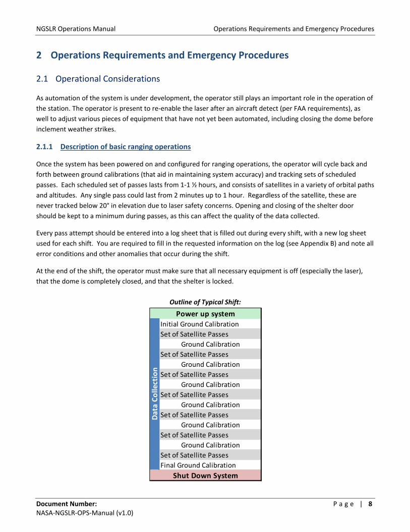
Once the system has been powered on and configured for ranging operations, the operator will cycle back and
forth between ground calibrations (that aid in maintaining system accuracy) and tracking sets of scheduled
passes. Each scheduled set of passes lasts from 1‐1 ½ hours, and consists of satellites in a variety of orbital paths
and altitudes. Any single pass could last from 2 minutes up to 1 hour. Regardless of the satellite, these are
never tracked below 20° in elevation due to laser safety concerns. Opening and closing of the shelter door
should be kept to a minimum during passes, as this can affect the quality of the data collected.
Every pass attempt should be entered into a log sheet that is filled out during every shift, with a new log sheet
used for each shift. You are required to fill in the requested information on the log (see Appendix B) and note all
error conditions and other anomalies that occur during the shift.
At the end of the shift, the operator must make sure that all necessary equipment is off (especially the laser),
that the dome is completely closed, and that the shelter is locked.
Outline of Typical Shift:
Initial Ground Calibration
Set of Satellite Passes
Ground Calibration
Set of Satellite Passes
Ground Calibration
Set of Satellite Passes
Ground Calibration
Set of Satellite Passes
Ground Calibration
Set of Satellite Passes
Ground Calibration
Set of Satellite Passes
Ground Calibration
Set of Satellite Passes
Final Ground Calibration
Data Collection
Power up system
Shut Down System
NGSLR Operations Manual Operations Requirements and Emergency Procedures
Document Number: P a g e | 9 NASA‐NGSLR‐OPS‐Manual (v1.0)
2.1.2 Reasons to stop tracking
Laser Ranging occurs for scheduled passes as cloud conditions and ILRS restricted tracking parameters† permit.
Exceptions include the following conditions where the dome must be closed in order to protect sensitive
equipment:
1. Precipitation of any kind
2. Sustained gusts of greater than 40 mph (17.8 m/s)
3. Temperatures that are above 122° F (50° C) or below 14° F (‐10° C)*
† Some missions define whether they will allow satellite tracking at a particular time. See the ILRS website for more
information on tracking restrictions at: http://ilrs.gsfc.nasa.gov
2.1.3 System Readiness
Depending upon past tracking performance (both NGSLR and LRO), a decision must be made as to whether any
system alignment procedures or checks need to be performed.
Three levels of tracking readiness can be identified for tracking operations, they include:
1. SLR tracking operations are successful in previous attempts and no changes have been made – The
system is tracking successfully (with or without pointing bias), and no additional alignment checks are
needed. Attempt tracking operations.
2. Previous SLR tracking engagements have been unsuccessful for unknown reasons – Attempt tracking,
noting any unusual biases, system errors, or hardware anomalies on the log sheet. Immediately stop
tracking should a safety related failure occur.
3. Maintenance, alignment, and or development work is required to bring the system up to full tracking
readiness – Tracking is not possible in this state. This may include laser or equipment replacement,
timing or star calibration issues, or equipment failure.
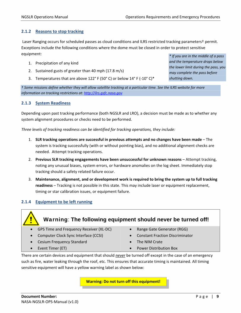
2.1.4 Equipment to be left running
Warning: The following equipment should never be turned off!
GPS Time and Frequency Receiver (XL‐DC)
Computer Clock Sync Interface (CCSI)
Cesium Frequency Standard
Event Timer (ET)
Range Gate Generator (RGG)
Constant Fraction Discriminator
The NIM Crate
Power Distribution Box
There are certain devices and equipment that should never be turned off except in the case of an emergency
such as fire, water leaking through the roof, etc. This ensures that accurate timing is maintained. All timing
sensitive equipment will have a yellow warning label as shown below:
Warning: Do not turn off this equipment!
* If you are in the middle of a pass
and the temperature drops below
the lower limit during the pass, you
may complete the pass before
shutting down.

NGSLR Operations Manual Operations Requirements and Emergency Procedures
Document Number: P a g e | 1 0 NASA‐NGSLR‐OPS‐Manual (v1.0)
2.1.5 Temperature stability inside the shelter
Due to the fact that the equipment within NGSLR requires a narrow range of temperatures to operate, do not
adjust or otherwise change the settings on the thermostat.
2.1.6 Coordination with other onsite Space Geodesy techniques
NGSLR shares the Goddard Geophysical and Astronomical Observatory (GGAO) site with various other
experiments, and must be able to operate without adversely affecting other projects. NGSLR may also be called
upon to perform synchronous tracking with other co‐located laser stations.
2.1.6.1 Radar interference prevention for VLBI
The VLBI project, co‐located at GGAO, uses a radio telescope to record faint signals from distant radio sources.
In order to protect the ultra‐sensitive VLBI receiver from damage from the LHRS radar, a redundant set of
pointing masks have been developed, preventing RF transmission in the direction of the VLBI antenna. The first
mask is software based, and prevents the telescope (and the slaved LHRS radar) from pointing in the direction of
the VLBI station. The second mask is installed in the LHRS system, and prevents the radar from transmitting if it
were to ever point in the direction of the VLBI telescope.
NGSLR Operations Manual Operations Requirements and Emergency Procedures
Document Number: P a g e | 1 1 NASA‐NGSLR‐OPS‐Manual (v1.0)
2.2 LHRS/IOC Verification
The complete LHRS/IOC Verification Procedure should be performed on a quarterly basis, as well as any time the
LHRS, IOC, or any of the associated hardware systems are modified or repaired. A subset of the LHRS/IOC
Verification Procedure is performed on a weekly basis, to ensure the continued safe operation between the
quarterly checks. The procedure is listed in NGSLR Safety Manual. Please note that there is a separate LHRS/IOC
checklist for SLR and LRO operations.
2.3 Crew requirements for FAA compliance at NGSLR
The system’s proximity to multiple airports in the Baltimore/Washington corridor requires that additional
precautions be taken in regards to laser safety and aircraft. Because of this, the operator is required to call the
National Capitol Regional Coordination Center (NCRCC) according to the following schedule:
At least 2 hours prior to the first pass of the week to notify them of weekly operations
Upon commencement of the first pass for the week
Upon conclusion of the last pass of the week
Operations are to be conducted consistent with the operations times provided to the FAA, and should always be
provided in Eastern Daylight or Eastern Standard Time. In addition, it is imperative that you record the name of
the person you talked to at the FAA and record that contact information in the log book, along with the date and
time. See the NGSLR Phone Number and Contact Sheet for the NCRCC Phone number.
Example Conversations for each contact with the FAA
Two Hours Prior ‐ Call 2 hours before the first pass of the week. Say something similar to:
“This is Joe Smith at the Goddard Space Flight Center. I am calling to inform you that we will be commencing
laser ranging operations today at [time] ending operations at [date/time].”
15 Minutes Before ‐ Call 15 minutes before the first pass of the week. Say something similar to:
“This is Joe Smith at the Goddard Space Flight Center. I am calling to inform you that we are commencing laser
ranging operations.”
At the end of your Shift ‐ Call at the end of operations for the week. Say something similar to:
“This is Joe Smith at the Goddard Space Flight Center. I am calling to inform you that we are ending laser
operations for the week. Operations will begin again on [date/time].”
NGSLR Operations Manual Operations Requirements and Emergency Procedures
Document Number: P a g e | 1 2 NASA‐NGSLR‐OPS‐Manual (v1.0)
2.4 In Case of Improper Function of Laser Safety Equipment
IF THE OPERATION OF THE LHRS, IOC OR ANY ASSOCIATED SAFETY HARDWARE
BECOMES SUSPECT, DO NOT CONTINUE TRACKING OPERATIONS!
In the event that the operation of safety hardware becomes suspect or malfunctions, IMMEDIATELY stop
operations and contact the appropriate person (NASA SLR Lead, NASA SLR Manager or Lead Hardware
Engineers) as directed on the Emergency Contact sheet posted on the inside of the shelter door.
DO NOT CONTINUE OPERATIONS UNTIL GIVEN CONCURRENCE
BY EITHER THE NASA SLR LEAD OR NASA SLR MANAGER.
2.5 In Case of Laser Hazard Event
IF YOU ENCOUNTER A LASER HAZARD EVENT, CEASE OPERATIONS AND CONTACT THE
NASA SLR LEAD AND NASA SLR MANAGER IMMEDIATELY!
Any of the following constitutes a Laser Hazard Event:
If the operator perceives that an aircraft entered the 2° inscribed circle on the telescope camera
monitor, yet a laser disable did not occur
If an aircraft is illuminated by the laser
If personnel are injured by the laser in any way
Refer to Section 2.6.3 of this manual for the required procedure that covers these situations.

NGSLR Operations Manual Operations Requirements and Emergency Procedures
Document Number: P a g e | 1 3 NASA‐NGSLR‐OPS‐Manual (v1.0)
2.6 Emergency Procedures
In the event of an emergency, use the below information to help you properly deal with the situation.
2.6.1 Emergency Contact Information
Goddard Emergency/Rescue:
Removed (jlfm)
Site Address:
Removed (jlfm)
Non‐Life Threatening Emergencies:
Removed (jlfm) GSFC Help Desk for major problems such as loss of power or flooding (Open: 24 X 7)
General Maintenance Issues: (non‐emergency)
Removed (jlfm) GSFC Help Desk for non‐emergency problems (clogged toilets, lights burned out, etc)
2.6.2 Injury/Imminent Danger to Personnel
If a hazardous condition is detected that is caused by equipment in the system, immediately perform an emergency power down of the equipment. If someone has been injured and/or there are people in imminent danger of injury, immediately warn all affected personnel and evacuate to a safe area. Once you are in a safe area, call the GSFC Emergency Console Operator by dialing 911. Some typical conditions that require action include:
• Detection of flame, smoke, or other evidence of fire
• The spill of a highly toxic chemical
• Attempted access by unauthorized personnel
2.6.3 Laser Hazard Event / Close Calls
In the event of a close call or other event involving the laser or laser safety controls the operator shall:
1. Immediately STOP operations! 2. Turn off the laser system 3. Notify the NASA SLR Lead and the NASA SLR Manager 4. Quarantine the following:
a. Station hardware b. System software c. Operator’s log book d. Pass data for the laser and the radar e. Current operating procedures used by the operations and engineering staff f. Any other items identified by the NASA SLR Lead/Manager
5. The NASA SLR Lead will notify the Government project office 6. The operator is not to continue operations until given concurrence by the NASA SLR Lead/Manager

NGSLR Operations Manual Preparing for Tracking Operations
Document Number: P a g e | 1 4 NASA‐NGSLR‐OPS‐Manual (v1.0)
3 Preparing for Tracking Operations
3.1 Initial Preparations
1. Fill out the Operations Log – At the commencement of your shift, fill out the NGSLR Operations Log as
shown in Appendix B. Make sure to keep this log sheet in a convenient place as you will continue to
enter additional information with each pass / ground calibration that is performed.
If this is the first satellite track of the week, perform step #2, otherwise continue to step 3.
2. Call the FAA – Inform the FAA of pending operations immediately after beginning the operations log.
a. Call the FAA. (See the posting in the shelter for the current number)
b. Say something similar to:
“This is Joe Smith at the Goddard Space Flight Center. I am calling to inform you that we are
commencing laser ranging operations.”
c. Write down the name of person spoken to in the Operations Log, along with the current time.
3. Verify that the LRO mirror has been removed – If the 45° LRO transmit mirror is still in place, flip the
lever to the OFF position and move the mount to a safe location off to the side (Figures 3‐1 & 3‐2). This
optic is only used during LRO operations.
Figure 3‐1: LRO Insertion Mirror Figure 3‐2: Diagram of the optical bench showing the operational location
of the LRO Insertion Mirror [1a] and the storage location [1b]. The
Autocollimator Turning mirror is shown on the right [2]
4. Verify that the Autocollimator Turning mirror has been lowered (Figure 3‐2) – If necessary, use the controller mounted upside down on the telescope pier extension to drop the mirror below the beam height.
NGSLR Operations Manual Preparing for Tracking Operations
Document Number: P a g e | 1 5 NASA‐NGSLR‐OPS‐Manual (v1.0)
3.2 Power Up Sequence
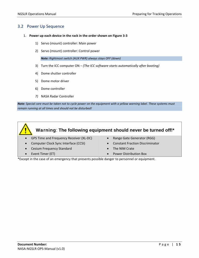
1. Power up each device in the rack in the order shown on Figure 3‐3
1) Servo (mount) controller: Main power
2) Servo (mount) controller: Control power
Note: Rightmost switch (AUX PWR) always stays OFF (down)
3) Turn the ICC computer ON – (The ICC software starts automatically after booting)
4) Dome shutter controller
5) Dome motor driver
6) Dome controller
7) NASA Radar Controller
Note: Special care must be taken not to cycle power on the equipment with a yellow warning label. These systems must
remain running at all times and should not be disturbed!
Warning: The following equipment should never be turned off!*
GPS Time and Frequency Receiver (XL‐DC)
Computer Clock Sync Interface (CCSI)
Cesium Frequency Standard
Event Timer (ET)
Range Gate Generator (RGG)
Constant Fraction Discriminator
The NIM Crate
Power Distribution Box
*Except in the case of an emergency that presents possible danger to personnel or equipment.

NGSLR Operations Manual Preparing for Tracking Operations
Document Number: P a g e | 1 6 NASA‐NGSLR‐OPS‐Manual (v1.0)
Figure 3‐3: Power up sequence
NGSLR Operations Manual Preparing for Tracking Operations
Document Number: P a g e | 1 7 NASA‐NGSLR‐OPS‐Manual (v1.0)
2. Open the Dome shutter – To open the dome, rotate the SHUTTER switch to OPEN and then turn the key
to ENABLE. The OPEN light will blink green until the dome is completely open, when the light will
become solid. Go on to the next step while the shutter is opening.
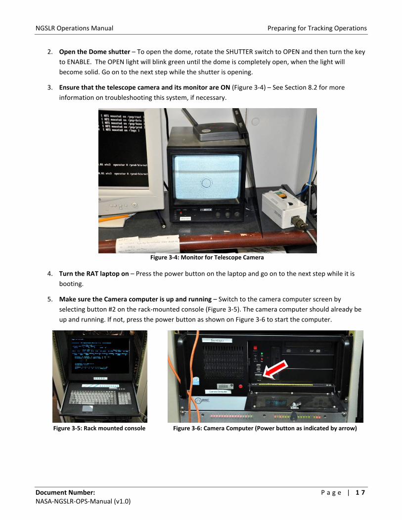
3. Ensure that the telescope camera and its monitor are ON (Figure 3‐4) – See Section 8.2 for more
information on troubleshooting this system, if necessary.
Figure 3‐4: Monitor for Telescope Camera
4. Turn the RAT laptop on – Press the power button on the laptop and go on to the next step while it is
booting.
5. Make sure the Camera computer is up and running – Switch to the camera computer screen by
selecting button #2 on the rack‐mounted console (Figure 3‐5). The camera computer should already be
up and running. If not, press the power button as shown on Figure 3‐6 to start the computer.
Figure 3‐5: Rack mounted console
Figure 3‐6: Camera Computer (Power button as indicated by arrow)
NGSLR Operations Manual Preparing for Tracking Operations
Document Number: P a g e | 1 8 NASA‐NGSLR‐OPS‐Manual (v1.0)
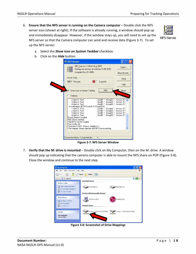
6. Ensure that the NFS server is running on the Camera computer – Double click the NFS
server icon (shown at right). If the software is already running, a window should pop up
and immediately disappear. However, if the window stays up, you will need to set up the
NFS server so that the Camera computer can send and receive data (Figure 3‐7). To set
up the NFS server:
a. Select the Show Icon on System Taskbar checkbox.
b. Click on the Hide button.
Figure 3‐7: NFS Server Window
7. Verify that the M: drive is mounted – Double click on My Computer, then on the M: drive. A window
should pop up indicating that the camera computer is able to mount the NFS share on POP (Figure 3‐8).
Close the window and continue to the next step.
Figure 3‐8: Screenshot of Drive Mappings

NGSLR Operations Manual Preparing for Tracking Operations
Document Number: P a g e | 1 9 NASA‐NGSLR‐OPS‐Manual (v1.0)
8. Ensure that the Sky Camera software is running in the background (minimized) – If the
program is running, it will show up on the Windows XP taskbar (Figure 3‐9). If it isn’t
running, click on the program icon (shown at right) to start the program .
Figure 3‐9: Camera computer status bar showing that the Sky Camera Program is running
9. Once the Dome Shutter is fully open, turn the enable key back to the center position (pointing up).
10. Log into DAM at the DAM/POP terminal – To do this, go to Screen 2 by pressing ALT‐F3. Look for the
number [2] in the lower left corner of the display to indicate that you are on the right screen (Figure 3‐
10). Enter the username and password. DAM will begin the login process and start multiple programs
that will run in the background.
Figure 3‐10: Console area showing the DAM/POP Terminal
11. Log into POP at the DAM/POP terminal – After all of DAM’s programs have started, the password
prompt for POP will show up on the same screen (Figure 3‐10). Enter the POP password.
12. Log into the RAT laptop at the Operator Console using the Technical User account – The Ratgui
software will automatically start, opening the user interface (Figure 3‐11).
Figure 3‐11: Main window for Ratgui as it appears after starting RAT

NGSLR Operations Manual Preparing for Tracking Operations
Document Number: P a g e | 2 0 NASA‐NGSLR‐OPS‐Manual (v1.0)
13. Mount NFS Shares on RAT – Click on each of the buttons in the RAT interface (as shown in Figure 3‐12)
to mount the NFS shares for DAM and POP. The buttons will change from red to green if the mount is
successful.
Figure 3‐12: Mounted and Un‐mounted NFS Shares
14. Connect to Ratsnest – On the Ratgui window, select the Not Connected button (Figure 3‐13). If the
connection to Ratsnest is successful, the button will turn green and the label will change to Connected.
Figure 3‐13: Not Connected / Connected Button
15. Verify that Ratgui is actively controlling the system – Verify that the button in the upper left hand
corner of Ratgui shows that the system is active, not inactive. The top part of the interface now should
look similar to Figure 3‐14.
Figure 3‐14: Ratgui Connected to Ratsnest and to the POP and DAM NFS shares

NGSLR Operations Manual Preparing for Tracking Operations
Document Number: P a g e | 2 1 NASA‐NGSLR‐OPS‐Manual (v1.0)
16. Open the main Control Windows – Open the Control windows, configuring each item as directed and
leaving the window open. Do not click Apply on any of the windows until POP is started. You may move
or resize the windows as necessary to allow access to all of these control windows.
a. Control => Search; Select the Stop Search checkbox (Figure 3‐15).
Figure 3‐15: Search control window
b. Control => Decisions; Select the following checkboxes (Figure 3‐16).
Do not use Quad Detector Biases
Do not use Time Bias Solution
Do not use Range Bias Solution
Figure 3‐16: Decisions: Control & Override window
NGSLR Operations Manual Preparing for Tracking Operations
Document Number: P a g e | 2 2 NASA‐NGSLR‐OPS‐Manual (v1.0)
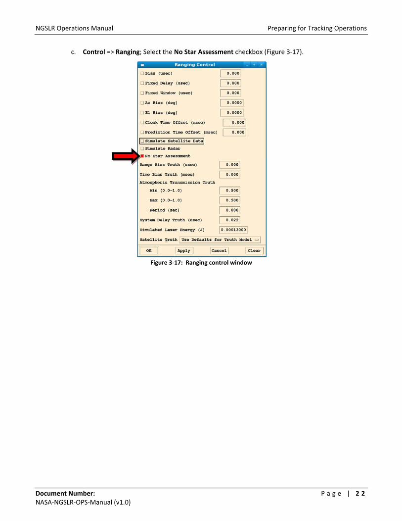
c. Control => Ranging; Select the No Star Assessment checkbox (Figure 3‐17).
Figure 3‐17: Ranging control window

NGSLR Operations Manual Preparing for Tracking Operations
Document Number: P a g e | 2 3 NASA‐NGSLR‐OPS‐Manual (v1.0)
d. Control => Sensors; Select all (6) Sky Clarity checkboxes (Figure 3‐18).
Note: The below selections disable the use of the Sky Camera, as the cloud decision process is still undergoing
development and testing. Once this is complete, it will no longer be necessary to disable this functionality.
Figure 3‐18: Sensor control window
NGSLR Operations Manual Preparing for Tracking Operations
Document Number: P a g e | 2 4 NASA‐NGSLR‐OPS‐Manual (v1.0)
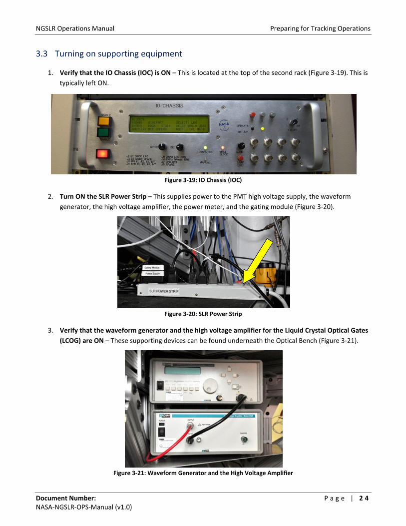
3.3 Turning on supporting equipment
1. Verify that the IO Chassis (IOC) is ON – This is located at the top of the second rack (Figure 3‐19). This is
typically left ON.
Figure 3‐19: IO Chassis (IOC)
2. Turn ON the SLR Power Strip – This supplies power to the PMT high voltage supply, the waveform
generator, the high voltage amplifier, the power meter, and the gating module (Figure 3‐20).
Figure 3‐20: SLR Power Strip
3. Verify that the waveform generator and the high voltage amplifier for the Liquid Crystal Optical Gates
(LCOG) are ON – These supporting devices can be found underneath the Optical Bench (Figure 3‐21).
Figure 3‐21: Waveform Generator and the High Voltage Amplifier

NGSLR Operations Manual Preparing for Tracking Operations
Document Number: P a g e | 2 5 NASA‐NGSLR‐OPS‐Manual (v1.0)
4. Verify that the waveform generator is set to use waveform #1 – Select the WVFM button, then use the
Down Arrow to display the current setting on the LCD screen (Figure 3‐22).
Figure 3‐22: Adjusting the Waveform Generator
5. Turn the overhead lights OFF in the back area – To prevent damage to the PMT, the lights must remain
OFF whenever the Bertran high voltage power supply is turned ON.
Warning: The lights in the Laser Operations Area must be OFF before proceeding to the next
step! Permanent damage to the PMT could result.
Warning: Do not exceed the maximum voltage, or increase the voltage too quickly.
Permanent damage to the PMT could result.
6. Power ON the Bertran high voltage power supply – Supplying power to the PMT, this device is located
under the Optical Bench (Figure 3‐23).
a. Flip the ON/OFF toggle switch located on the left hand side to the ON position.
b. Slowly ramp up the operating voltage in 500 volt increments from ‐450 to ‐2950 volts over the
span of 1 minute.
c. The MCP should be powered on for 20‐30 minutes before any data is taken.
Figure 3‐23: Bertran High Voltage Power Supply
7. Slide the protective card in front of the light tight box to the UNBLOCKED position – This is in place as a manual backup to the shutter, but must be removed before tracking.

NGSLR Operations Manual Preparing for Tracking Operations
Document Number: P a g e | 2 6 NASA‐NGSLR‐OPS‐Manual (v1.0)
3.4 Safety protocol prior to turning on the SLR laser
1. Ensure that the stairway chain and warning sign are in place on the ladder – This is to prevent
unauthorized access to the roof deck (Figure 3‐24).
Figure 3‐24: Stairway chain and warning sign
Figure 3‐25: Water gauge on the SLR laser chiller
2. Ensure that the front door to the shelter is closed
3. Check the water gauge on the front of the chiller to ensure that it has sufficient coolant (Figure 3‐25)
4. Verify that coolant hoses are properly connected to the laser system – Ensure that the hoses are
connected and that there is no leakage of coolant from the laser controller, chiller, or the laser head
(Figures 3‐26 & 3‐27).
Figure 3‐26: Coolant hoses for the Chiller and Controller
Figure 3‐27: Coolant hoses for the Laser Head
5. Ensure that the alignment flip mirrors are out of the beam path
6. Close the laser curtain, ensuring that both entrances are fully closed
7. Turn on the lighted Laser Warning sign (Figure 3‐28)
Figure 3‐28: Laser Warning sign

NGSLR Operations Manual Preparing for Tracking Operations
Document Number: P a g e | 2 7 NASA‐NGSLR‐OPS‐Manual (v1.0)
3.5 Powering up and starting the SLR Laser Controller
Warning: Do not perform the below steps without having completed the steps listed in the
previous section. Make sure to inform all present prior to activating the laser. Failure to follow
these guidelines can result in eye damage to anyone exposed to the beam.
1. Turn ON the laser controller
a. Flip On/Off red rocker switch labeled Power on the laser driver to the ON position (Figure 3‐29).
Verify that the chiller pump is running (motor should be audible).
b. Turn Laser Enable key to ON position (Figure 3‐29).
Figure 3‐29: Front Panel of the Laser Controller
c. Exit the laser operations area, closing the laser curtain behind you.
2. Start the SLR Laser using the control software on the Camera computer
a. Click on the icon for the SLR Laser Control software (Figure 3‐30). This will
open two windows as shown on Figure 3‐31.
Note: When the software is launched, two windows will appear: one that is the GUI interface for the laser and the
other (with the black background) for the Python interpreter supporting it. Do not close the window with the black
background; closing it will close the GUI as well.
b. Select the STARTUP button (Figure 3‐31)
Figure 3‐31: PI Laser Interface prior to starting the laser
Figure 3‐30: SLR Laser
Control icon

NGSLR Operations Manual Preparing for Tracking Operations
Document Number: P a g e | 2 8 NASA‐NGSLR‐OPS‐Manual (v1.0)
Warning: Inform all present that the laser is being turned on. Make sure to close the laser curtain and that any personnel behind the laser curtain are wearing protective eyewear before turning on the laser. Minimum eyewear optical density for the SLR laser at tracking power is >4.7 ND @ 532nm. Failure to follow these guidelines can result in severe eye damage to anyone exposed to the beam.
c. Once the STARTUP button has turned dark green, click on the TRACKING button (Figure 3‐32).
It will light up with a bright green color when the laser is ready to begin tracking.
Figure 3‐32: PI Laser interface showing that the laser in tracking mode
Note: The laser will not actually begin firing until the software is running and the laser has been enabled through the IO
Chassis.
NGSLR Operations Manual Performing Tracking Operations
Document Number: P a g e | 2 9 NASA‐NGSLR‐OPS‐Manual (v1.0)
4 Performing Tracking Operations
Normal operation of the system includes alternating ground calibration and satellite passes. Careful attention
must be paid to each step in this manual in order to ensure safe and efficient operation of the system and the
continued collection of high quality scientific data.
All passes and ground calibrations should be recorded on the NGSLR Operations Log Sheet. See the example log
sheet in the appendix for details on specific sections that should be filled out. Any problems, configuration
changes, or other notable events that occurred during the shift should be recorded, along with the date and
time, at the end of the log sheet. This can serve as an essential troubleshooting tool for the NGSLR development
staff in tracking down the problem. In addition, please remember that each shift should start and end with a
ground calibration that may or may not be set in the schedule. It is the operator’s responsibility to ensure that
these calibrations are performed.
During operations, the operator should remain alert regarding precipitation, temperature, and wind speed
outside the normal operating range as defined in Section 2.1.2. The dome MUST be closed immediately
whenever precipitation is imminent, or whenever wind gusts are above 40 mph (~17.8 m/s). Operations should
not continue if the temperature falls outside of the normal operating range. However, if the temperature drops
below the lower limit during the pass, you may complete the pass before shutting down. During both tracking
and ground calibration, the operator should refrain from opening and closing the door as this will affect data
quality. Never operate with the door open due to laser safety concerns and the possibility of reduced data
quality due to temperature fluctuation.
4.1 Ground Calibration
Ground calibration is a technique to measure the station system delay (the difference between the theoretical
time it should take for light to travel through the atmosphere in the horizontal path to the target and back, and
the time that is actually measured by the system). Range measurements to satellite targets need to have this
delay time removed to produce an accurate product.
Note: This section assumes that all equipment and software are running and configured as defined in Section 3.
Things to check for: LRO insertion mirror removed, LHRS ON, Autocollimator mirror retracted, PMT manual block removed
1. Ensure that the MCP has been powered up for 20‐30 minutes to achieve good data stability
2. Run POP – At the DAM/POP terminal (screen #2), start the operational software by typing:
/prod/bin/pop –I <ENTER>
Note: Be sure to start the POP software on the “top” part of the minute (between 5 and 25 seconds into the minute) as listed
on the GPS Time and Frequency Receiver. POP can potentially crash if it is started too close to the rollover of the minute,
which will result in a long reboot (~15 minutes).
3. Click the Apply buttons on all of the RAT control menus – This sends the operator override settings to
the DAM/POP software.
NGSLR Operations Manual Performing Tracking Operations
Document Number: P a g e | 3 0 NASA‐NGSLR‐OPS‐Manual (v1.0)
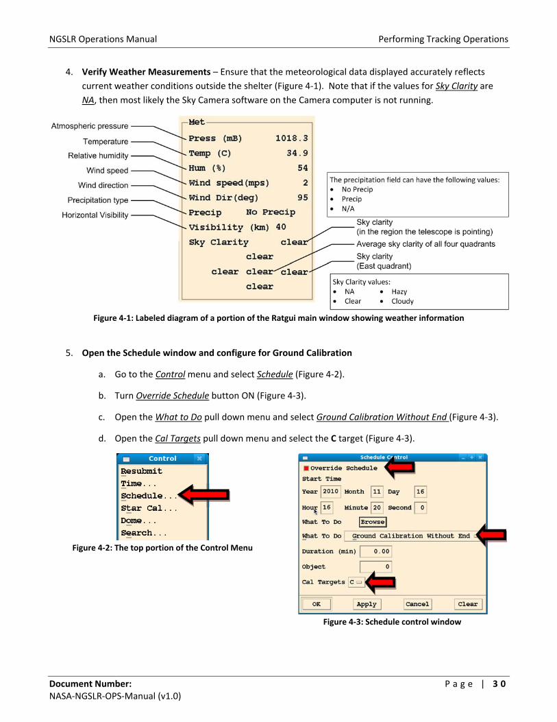
4. Verify Weather Measurements – Ensure that the meteorological data displayed accurately reflects
current weather conditions outside the shelter (Figure 4‐1). Note that if the values for Sky Clarity are
NA, then most likely the Sky Camera software on the Camera computer is not running.
Figure 4‐1: Labeled diagram of a portion of the Ratgui main window showing weather information
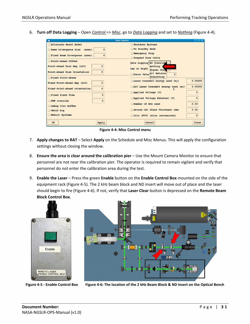
5. Open the Schedule window and configure for Ground Calibration
a. Go to the Control menu and select Schedule (Figure 4‐2).
b. Turn Override Schedule button ON (Figure 4‐3).
c. Open the What to Do pull down menu and select Ground Calibration Without End (Figure 4‐3).
d. Open the Cal Targets pull down menu and select the C target (Figure 4‐3).
Figure 4‐2: The top portion of the Control Menu
Figure 4‐3: Schedule control window
NGSLR Operations Manual Performing Tracking Operations
Document Number: P a g e | 3 1 NASA‐NGSLR‐OPS‐Manual (v1.0)
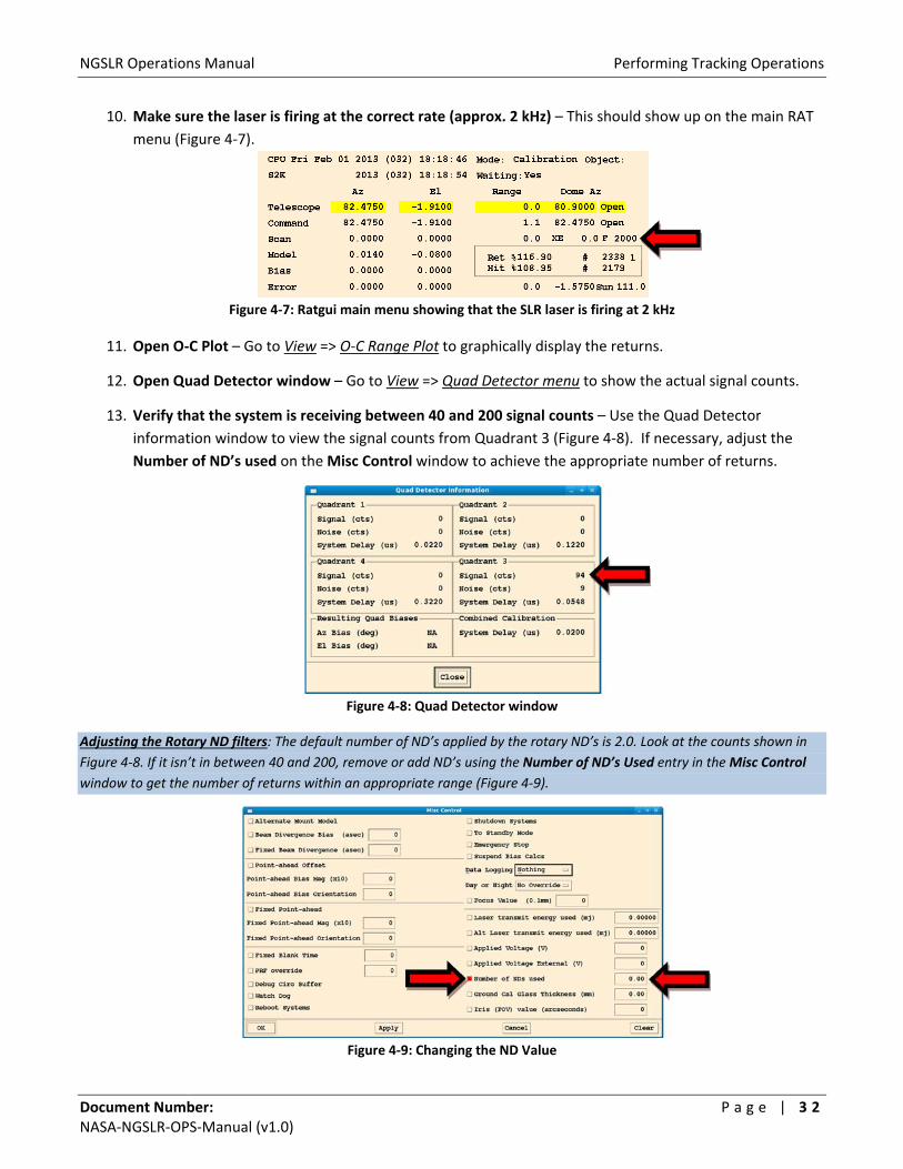
6. Turn off Data Logging – Open Control => Misc, go to Data Logging and set to Nothing (Figure 4‐4).
Figure 4‐4: Misc Control menu
7. Apply changes to RAT – Select Apply on the Schedule and Misc Menus. This will apply the configuration
settings without closing the window.
8. Ensure the area is clear around the calibration pier – Use the Mount Camera Monitor to ensure that
personnel are not near the calibration pier. The operator is required to remain vigilant and verify that
personnel do not enter the calibration area during the test.
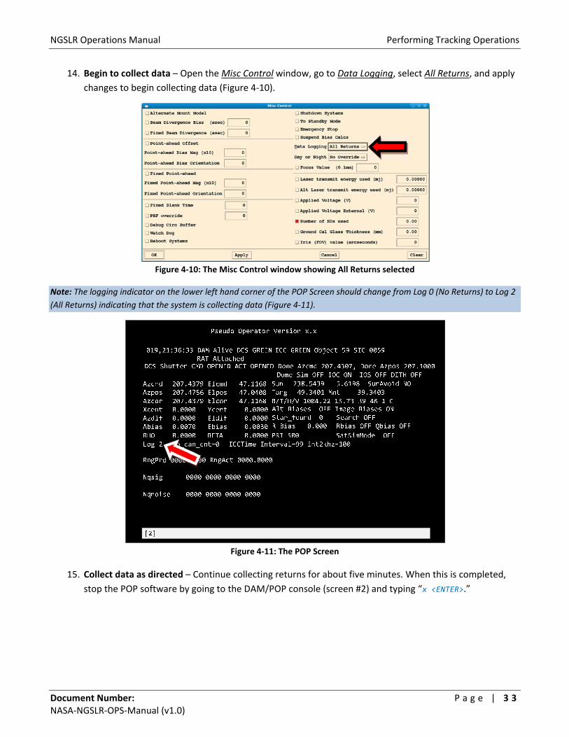
9. Enable the Laser – Press the green Enable button on the Enable Control Box mounted on the side of the
equipment rack (Figure 4‐5). The 2 kHz beam block and ND insert will move out of place and the laser
should begin to fire (Figure 4‐6). If not, verify that Laser Clear button is depressed on the Remote Beam
Block Control Box.
Figure 4‐5 ‐ Enable Control Box
Figure 4‐6: The location of the 2 kHz Beam Block & ND Insert on the Optical Bench
NGSLR Operations Manual Performing Tracking Operations
Document Number: P a g e | 3 2 NASA‐NGSLR‐OPS‐Manual (v1.0)
10. Make sure the laser is firing at the correct rate (approx. 2 kHz) – This should show up on the main RAT
menu (Figure 4‐7).
Figure 4‐7: Ratgui main menu showing that the SLR laser is firing at 2 kHz
11. Open O‐C Plot – Go to View => O‐C Range Plot to graphically display the returns.
12. Open Quad Detector window – Go to View => Quad Detector menu to show the actual signal counts.
13. Verify that the system is receiving between 40 and 200 signal counts – Use the Quad Detector
information window to view the signal counts from Quadrant 3 (Figure 4‐8). If necessary, adjust the
Number of ND’s used on the Misc Control window to achieve the appropriate number of returns.
Figure 4‐8: Quad Detector window
Adjusting the Rotary ND filters: The default number of ND’s applied by the rotary ND’s is 2.0. Look at the counts shown in
Figure 4‐8. If it isn’t in between 40 and 200, remove or add ND’s using the Number of ND’s Used entry in the Misc Control
window to get the number of returns within an appropriate range (Figure 4‐9).
Figure 4‐9: Changing the ND Value
NGSLR Operations Manual Performing Tracking Operations
Document Number: P a g e | 3 3 NASA‐NGSLR‐OPS‐Manual (v1.0)
14. Begin to collect data – Open the Misc Control window, go to Data Logging, select All Returns, and apply
changes to begin collecting data (Figure 4‐10).
Figure 4‐10: The Misc Control window showing All Returns selected
Note: The logging indicator on the lower left hand corner of the POP Screen should change from Log 0 (No Returns) to Log 2
(All Returns) indicating that the system is collecting data (Figure 4‐11).
Figure 4‐11: The POP Screen
15. Collect data as directed – Continue collecting returns for about five minutes. When this is completed,
stop the POP software by going to the DAM/POP console (screen #2) and typing “x <ENTER>.”
NGSLR Operations Manual Performing Tracking Operations
Document Number: P a g e | 3 4 NASA‐NGSLR‐OPS‐Manual (v1.0)
4.2 Satellite Tracking Process
This assumes that all equipment and software are running and configured as defined in Section 3.
Things to check for: LRO insertion mirror removed, LHRS ON, Autocollimator mirror retracted, PMT manual block removed.
Warning: During operations the operator should remain alert for precipitation and wind speed.
The dome MUST be closed immediately whenever precipitation is imminent, or whenever wind
gusts are above 40 mph.
1. Ensure that the MCP has been powered up for 20‐30 minutes to achieve good data stability
2. Run POP – At the DAM/POP terminal (screen #2), start the operational software by typing:
/prod/bin/pop –I <ENTER>
Note: Be sure to start the POP software on the “top” part of the minute (between 5 and 25 seconds into the
minute) as listed on the GPS Time and Frequency Receiver. POP can potentially crash if it is started too close to the
rollover of the minute, which will result in a long reboot (~15 minutes).
3. Hit all the Apply buttons on all of the RAT control menus – This sends the operator override settings to
the DAM/POP software.
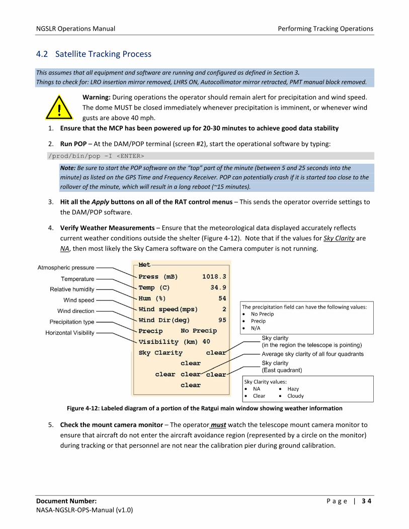
4. Verify Weather Measurements – Ensure that the meteorological data displayed accurately reflects
current weather conditions outside the shelter (Figure 4‐12). Note that if the values for Sky Clarity are
NA, then most likely the Sky Camera software on the Camera computer is not running.
Figure 4‐12: Labeled diagram of a portion of the Ratgui main window showing weather information
5. Check the mount camera monitor – The operator must watch the telescope mount camera monitor to
ensure that aircraft do not enter the aircraft avoidance region (represented by a circle on the monitor)
during tracking or that personnel are not near the calibration pier during ground calibration.

NGSLR Operations Manual Performing Tracking Operations
Document Number: P a g e | 3 5 NASA‐NGSLR‐OPS‐Manual (v1.0)
6. Look for Two kHz Laser Blocked – When the system is ready, the message “TwoKHz Laser BLOCKED” will flash on the POP screen (Figure 4‐13).
Figure 4‐13: “TwoKHz Laser BLOCKED” message on the DAM/POP terminal
7. Enable the Laser – Press the green Enable button on the Enable Control Box mounted on the side of the
equipment rack (Figure 4‐14). The 2 kHz beam block and ND insert will move out of place and the laser
should begin to fire (Figure 4‐15). If not, verify that Laser Clear button is depressed on the Remote
Beam Block Control Box.
Figure 4‐14: Enable Control Box Figure 4‐15: 2 kHz Beam Block & ND Insert
When the LHRS radar senses an aircraft getting close to the laser beam, it will immediately block the laser. When the
aircraft detect is clear, the message “TwoKHz Laser BLOCKED” will flash on the POP screen (Figure 4‐13). Check the
camera monitor to ensure that the aircraft has passed, then push the ENABLE button on the Remote Laser Enable Control
Box to re‐enable the laser.

NGSLR Operations Manual Performing Tracking Operations
Document Number: P a g e | 3 6 NASA‐NGSLR‐OPS‐Manual (v1.0)
8. Make sure the laser is firing at the correct rate (approx. 2 kHz) – This should show up on the main RAT
window (Figure 4‐16).
Figure 4‐16: Section of the Ratgui main window showing that the SLR laser is firing at 2 kHz
9. Verify that the system is receiving returns – Go to View => Realtime O‐C Plot (Figure 4‐17).
There should be a single blue line showing the return signal, with the speckled haze across the window representing
noise. See Section 8.6 for more details on what to do if returns are not detected.
Figure 4‐17: Real‐time O‐C Plot showing the detected return signals
10. If necessary, adjust Azimuth and Elevation biases – If return rate (signal counts) is low, or the target
cannot be found, the pointing bias may need to be adjusted. Use one of the two following methods:
a. Method 1: Use the Telescope bias window – Open the window by going to View => Az/El
Handpaddle and adjust Az/El Bias using the slider bars or by clicking in the window and selecting
Apply (Figure 4‐18).
Figure 4‐18: Telescope bias window (Az/El Handpaddle)

NGSLR Operations Manual Performing Tracking Operations
Document Number: P a g e | 3 7 NASA‐NGSLR‐OPS‐Manual (v1.0)
b. Method 2: Use the Ranging Control window – Open the window by going to Control =>
Ranging, selecting the Az and El Bias radio buttons [left], entering the bias value desired [right],
and applying the changes (Figure 4‐19).
Figure 4‐19: Ranging Control Window
11. Record the pass information in the log – Write down the satellite information in the NGSLR Operations
log including the biases used to track the satellite, along with any anomalies in the system that were
encountered.
Note: The system will automatically select the next target and begin tracking according to the priority assigned in the
schedule. If tracking of a target is unsuccessful, the operator can click the Next Target button in the main Ratgui window to
switch to the next target. Do not forget to fill out the Operation Log for the pass regardless of whether tracking was
successful or not.
12. Exit POP – When the set of passes is over, type “x <ENTER>” at the DAM/POP terminal. POP will count
down and then exit.
Note: If a ground calibration was not listed in the schedule, perform a ground calibration as listed in Section 4.1.

NGSLR Operations Manual Routine Alignment Verification
Document Number: P a g e | 3 8 NASA‐NGSLR‐OPS‐Manual (v1.0)
5 Routine Alignment Verification
The alignment of the mount throughout its range of motion must be routinely verified to ensure that the system
biases remain current, whether due to alignment creep or a change in season.
5.1 Performing a Star Calibration This section assumes that all equipment and software are running and configured as defined in Section 3.
Things to check for: LRO insertion mirror removed, LHRS ON, Autocollimator Mirror Retracted, Star Camera ON, SLR & LRO
Lasers OFF
The star calibration software calibrates the system using up to 50 stars to correct the pointing biases of the
system, known as mount model coefficients. Weather conditions permitting, this process may be performed on
a weekly basis, but no less than every few weeks. As the telescope will need to be able to capture the image of a
star, star calibrations are only able to be performed at night. This procedure is automated and takes typically
around 40 minutes to complete in a clear sky. It is wise to look at several stars after the calibration to make sure
pointing is nominally 1 millidegree or less at ~45° elevation in all sky sectors.
5.1.1 Star Calibration Procedure
1. Verify that the Dome shutter is open
2. Ensure that both the mount camera and its monitor are ON
3. Ensure that the Star Camera is turned ON – Look for the red LED on the back of the device.
Note: The star camera must be turned ON prior to starting the software. Otherwise, the Star Camera program will enter
simulation mode.
4. Start the Star Camera software – Go to the Camera computer and double click on the
icon to start the software (shown on right). This should open up the star camera
window (Figure 5‐1).
Figure 5‐1: Star Camera Window
Note: The “Take Images” override (F2)
should NEVER be turned on during a Star
Calibration or Star Assessment since this
will desynchronize POP and the Camera
Software and potentially cause the Star
Calibration or Star Assessment results to
be worthless! See arrow on Figure 5‐1 for
location of status bar.

NGSLR Operations Manual Routine Alignment Verification
Document Number: P a g e | 3 9 NASA‐NGSLR‐OPS‐Manual (v1.0)
5. On RAT, open the Schedule window and configure for Star Calibration
a. Go to the Control menu and select Schedule (Figure 5‐2).
Figure 5‐2: Control Menu
b. Select the Override Schedule button (Figure 5‐3).
c. Open the What to Do pull down menu and select Star Calibration (Figure 5‐3).
Figure 5‐3: Schedule control window
6. Run POP – At the DAM/POP terminal (screen #2), start the operational software by typing:
/prod/bin/pop –I <ENTER>
Note: Be sure to start the POP software on the “top” part of the minute (between 5 and 25 seconds into the minute) as listed
on the GPS Time and Frequency Receiver. POP can potentially crash if it is started too close to the rollover of the minute,
which will result in a long reboot (~15 minutes).
NGSLR Operations Manual Routine Alignment Verification
Document Number: P a g e | 4 0 NASA‐NGSLR‐OPS‐Manual (v1.0)
7. Apply changes to RAT – Hit Apply on the Schedule Menu. This will apply the configuration settings and
begin the Star Calibration. The telescope will move from star to star, center the image, then move to the
next star. If the software cannot find a star after several attempts to capture the star image, the
operator should use the Next Star button on the Star Calibration menu on RAT.
8. Verify that the meteorological data is being logged properly – Values for the pressure, temperature,
wind speed, etc. should all be within normal ranges.
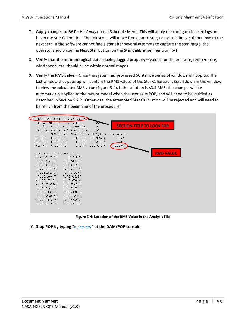
9. Verify the RMS value – Once the system has processed 50 stars, a series of windows will pop up. The
last window that pops up will contain the RMS values of the Star Calibration. Scroll down in the window
to view the calculated RMS value (Figure 5‐4). If the solution is <3.5 RMS, the changes will be
automatically applied to the mount model when the user exits POP, and will need to be verified as
described in Section 5.2.2. Otherwise, the attempted Star Calibration will be rejected and will need to
be re‐run from the beginning of the procedure.
Figure 5‐4: Location of the RMS Value in the Analysis File
10. Stop POP by typing “x <ENTER>” at the DAM/POP console
SECTION TITLE TO LOOK FOR
RMS VALUE
NGSLR Operations Manual Routine Alignment Verification
Document Number: P a g e | 4 1 NASA‐NGSLR‐OPS‐Manual (v1.0)
5.1.2 Verifying the Adjusted Pointing Biases produced by the Star Calibration
Note: This is a manual procedure which ensures that the telescope pointing remains accurate within a pre‐determined range using
the updated mount model. If not, a new automated Star Calibration will need to be performed.
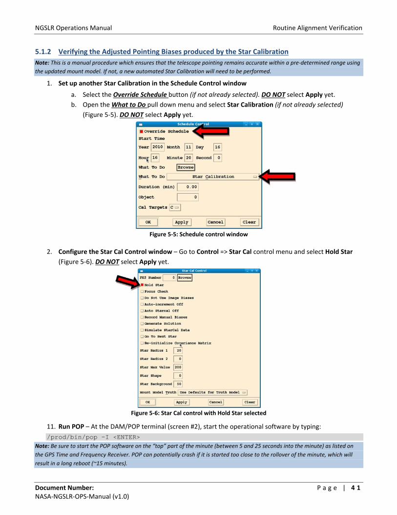
1. Set up another Star Calibration in the Schedule Control window
a. Select the Override Schedule button (if not already selected). DO NOT select Apply yet.
b. Open the What to Do pull down menu and select Star Calibration (if not already selected)
(Figure 5‐5). DO NOT select Apply yet.
Figure 5‐5: Schedule control window
2. Configure the Star Cal Control window – Go to Control => Star Cal control menu and select Hold Star
(Figure 5‐6). DO NOT select Apply yet.
Figure 5‐6: Star Cal control with Hold Star selected
11. Run POP – At the DAM/POP terminal (screen #2), start the operational software by typing:
/prod/bin/pop –I <ENTER> Note: Be sure to start the POP software on the “top” part of the minute (between 5 and 25 seconds into the minute) as listed on
the GPS Time and Frequency Receiver. POP can potentially crash if it is started too close to the rollover of the minute, which will
result in a long reboot (~15 minutes).

NGSLR Operations Manual Routine Alignment Verification
Document Number: P a g e | 4 2 NASA‐NGSLR‐OPS‐Manual (v1.0)
3. Apply changes to RAT – Click Apply on both the Schedule and the Star Cal control windows.
4. Open FK5 Lists – Go to the Star Cal control window and click on the Browse button (Figure 5‐9) – This
will open a list of stars that are currently visible along with a graphical representation of their location
(Figures 5‐7 and 5‐8). The radial lines on the plot represent the azimuth location of the star, and the
circular lines represent the elevation of the star.
5. Select a star that is near the 45° elevation mark in a particular quadrant – This is performed using the
point and click interface as shown in Figure 5‐8.
Figure 5‐7: Table of FK5 stars
Figure 5‐8: Map of FK5 stars
6. Slew to the selected star – Go to the Star Cal control window, de‐select Hold Star, select Go to Next Star
and click Apply (Figure 5‐9).
Figure 5‐9: Section of the Star Cal control window
Note: The telescope should
now be in the process of
slewing to the next star. As
it does, proceed to the next
step to hold that position
while the pointing biases for
that star are verified.

NGSLR Operations Manual Routine Alignment Verification
Document Number: P a g e | 4 3 NASA‐NGSLR‐OPS‐Manual (v1.0)
7. Hold the current star in position – Go to Control => Star Cal control menu and select Hold Star (Figure
5‐10). Wait to hit apply until you are on the star.
Figure 5‐10: Star Cal control with Hold Star selected
8. Verify that the Azimuth and Elevation Biases are within range – After the software captures the image
of the star and calculates the biases, check that the bias values are nominally 1 millidegree or less for
each star observed during the verification procedure (Figure 5‐11). If not, a second automated Star
Calibration will need to be performed and the subsequent results verified.
Figure 5‐11: Azimuth Bias (Abias) and Elevation Bias (Ebias) as shown on POP
9. Step through at least one star in each quadrant of the sky to verify the Star Calibration – Cycle
between step 6 and step 9 to compare the pointing biases of the telescope to a star in each quadrant of
the sky plot.
10. Exit POP – Go to the DAM/POP console (screen #2) and type “x <ENTER>.”

NGSLR Operations Manual Routine Alignment Verification
Document Number: P a g e | 4 4 NASA‐NGSLR‐OPS‐Manual (v1.0)
5.2 Performing a Star Assessment
This section assumes that all equipment and software are running and configured as defined in Section 3.
Things to check for: LRO insertion mirror removed, Autocollimator Mirror Retracted, Star Camera ON
Star assessments may be done at the beginning of a satellite pass and allow the telescope to align with a star
near to the beginning of the satellite pass in order to obtain azimuth and elevation biases to apply to the
upcoming satellite pass. As the telescope will need to be able to capture the image of a star, star assessments
are only able to be performed at night and require the use of the star camera.
To perform a Star Assessment, the procedure is the same as the steps used for Satellite Tracking, with the
exception of the setup of the Ranging control window as shown below (Figure 5‐12).
Figure 5‐12: Ranging control window for a Star Assessment
NGSLR Operations Manual Performing MINICO and Stability Tests
Document Number: P a g e | 4 5 NASA‐NGSLR‐OPS‐Manual (v1.0)
6 Performing MINICO and Stability Tests
6.1 Performing a Mini‐Collocation (MINICO)
The mini‐collocation serves as a way to verify that the system delay remains stable while ranging to multiple
stationary targets at various azimuth locations. The system delay refers to the timing delay within the system,
and is meant to verify that timing or pointing issues do not adversely affect ranging measurements.
Note: This section assumes that all equipment and software are running and configured as defined in Section 3.
1. Ensure that the MCP has been powered up for 20‐30 minutes to achieve good data stability
2. Ensure the area is clear around the calibration pier – Use the Mount Camera Monitor to ensure that
personnel are not near the calibration pier. The operator is required to remain vigilant and verify that
personnel do not enter the calibration area during the test.
3. Run POP – At the DAM/POP terminal (screen #2), start the operational software by typing:
/prod/bin/pop –I <ENTER>
Note: Be sure to start the POP software on the “top” part of the minute (between 5 and 25 seconds into the minute) as listed
on the GPS Time and Frequency Receiver. POP can potentially crash if it is started too close to the rollover of the minute,
which will result in a long reboot (~15 minutes)..
4. Hit all the Apply buttons on all of the RAT control menus – This sends the operator override settings to
the DAM/POP software.
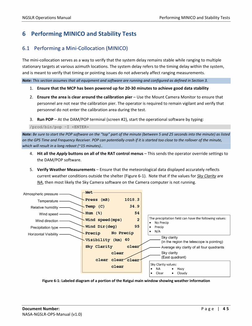
5. Verify Weather Measurements – Ensure that the meteorological data displayed accurately reflects
current weather conditions outside the shelter (Figure 6‐1). Note that if the values for Sky Clarity are
NA, then most likely the Sky Camera software on the Camera computer is not running.
Figure 6‐1: Labeled diagram of a portion of the Ratgui main window showing weather information

NGSLR Operations Manual Performing MINICO and Stability Tests
Document Number: P a g e | 4 6 NASA‐NGSLR‐OPS‐Manual (v1.0)
6. Open the Schedule window and configure for Ground Calibration – (Figure 6‐2)
a. On RAT, go to Control => Schedule.
b. Turn Override Schedule button on.
c. Open the What to Do pull down menu and select Ground Calibration without end.
d. Open the Cal Targets pull down menu and select the C target as the initial target.
Figure 6‐2: Schedule control window
7. Open the Control => Misc menu – From the Data Logging pull down menu, set Nothing (Figure 6‐3).
Figure 6‐3: Misc Control window
8. Hit Apply on the Schedule and Misc windows – This will apply the configuration settings
without closing the window.
9. Press the Enable button on the Enable Control Box – (Figure 6‐4)
Note: The 2 kHz beam block should move out of place and the laser should begin to fire. If not, verify that
the Laser Clear button is active on the white Remote Beam Block Control box at the operator’s console.
See Section 8.5 for additional troubleshooting steps if the laser will not fire.
NGSLR Operations Manual Performing MINICO and Stability Tests
Document Number: P a g e | 4 7 NASA‐NGSLR‐OPS‐Manual (v1.0)
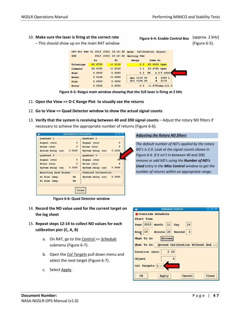
10. Make sure the laser is firing at the correct rate (approx. 2 kHz)
– This should show up on the main RAT window (Figure 6‐5).
Figure 6‐5: Ratgui main window showing that the SLR laser is firing at 2 kHz
11. Open the View => O‐C Range Plot to visually see the returns
12. Go to View => Quad Detector window to show the actual signal counts
13. Verify that the system is receiving between 40 and 200 signal counts – Adjust the rotary ND filters if
necessary to achieve the appropriate number of returns (Figure 6‐6).
Figure 6‐6: Quad Detector window
14. Record the ND value used for the current target on
the log sheet
15. Repeat steps 12‐14 to collect ND values for each
calibration pier (C, A, B)
a. On RAT, go to the Control => Schedule
submenu (Figure 6‐7).
b. Open the Cal Targets pull down menu and
select the next target (Figure 6‐7).
c. Select Apply.
Figure 6‐4: Enable Control Box
Adjusting the Rotary ND filters:
The default number of ND’s applied by the rotary
ND’s is 2.0. Look at the signal counts shown in
Figure 6‐6. If it isn’t in between 40 and 200,
remove or add ND’s using the Number of ND’s
Used entry in the Misc Control window to get the
number of returns within an appropriate range.

NGSLR Operations Manual Performing MINICO and Stability Tests
Document Number: P a g e | 4 8NASA‐NGSLR‐OPS‐Manual (v1.0)
Figure 6‐7: Schedule control window
16. Collect data from each calibration pier in this order: (C‐A‐B‐C‐A‐B‐C…)
a. On RAT, go to the Control => Schedule submenu (Figure 6‐8).
b. Open the Cal Targets pull down menu and select the next target (Figure 6‐8).
d. Adjust the ND value under the Misc Control menu as determined previously (Figure 6‐3).
c. Ensure data is being collected ‐ Go to the Misc Control menu and from the Data Logging pull down menu, set All Returns and select Apply.
d. Continue collecting returns for ten minutes, or the specified amount of time.
e. Record the ND value used for the current target on the log sheet.
f. Repeat step 16 until data has been collected for calibration piers in this order (C‐A‐B‐C‐A‐B‐C).
Figure 6‐8: Schedule control window
17. Exit POP to stop collecting returns – To do this, go to the DAM/POP console and type “x <ENTER>.”
NGSLR Operations Manual Performing MINICO and Stability Tests
Document Number: P a g e | 4 9 NASA‐NGSLR‐OPS‐Manual (v1.0)
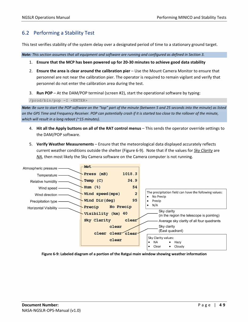
6.2 Performing a Stability Test
This test verifies stability of the system delay over a designated period of time to a stationary ground target.
Note: This section assumes that all equipment and software are running and configured as defined in Section 3.
1. Ensure that the MCP has been powered up for 20‐30 minutes to achieve good data stability
2. Ensure the area is clear around the calibration pier – Use the Mount Camera Monitor to ensure that
personnel are not near the calibration pier. The operator is required to remain vigilant and verify that
personnel do not enter the calibration area during the test.
3. Run POP – At the DAM/POP terminal (screen #2), start the operational software by typing:
/prod/bin/pop –I <ENTER>
Note: Be sure to start the POP software on the “top” part of the minute (between 5 and 25 seconds into the minute) as listed
on the GPS Time and Frequency Receiver. POP can potentially crash if it is started too close to the rollover of the minute,
which will result in a long reboot (~15 minutes).
4. Hit all the Apply buttons on all of the RAT control menus – This sends the operator override settings to
the DAM/POP software.
5. Verify Weather Measurements – Ensure that the meteorological data displayed accurately reflects
current weather conditions outside the shelter (Figure 6‐9). Note that if the values for Sky Clarity are
NA, then most likely the Sky Camera software on the Camera computer is not running.
Figure 6‐9: Labeled diagram of a portion of the Ratgui main window showing weather information
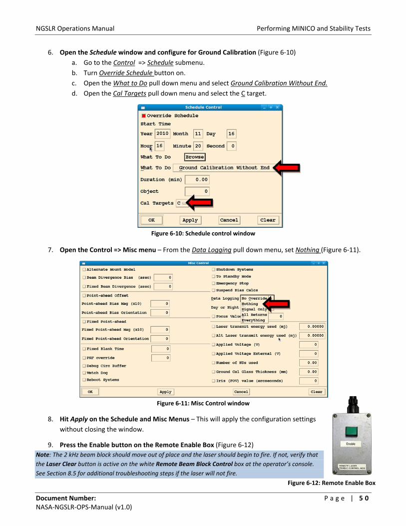
NGSLR Operations Manual Performing MINICO and Stability Tests
Document Number: P a g e | 5 0 NASA‐NGSLR‐OPS‐Manual (v1.0)
6. Open the Schedule window and configure for Ground Calibration (Figure 6‐10)
a. Go to the Control => Schedule submenu.
b. Turn Override Schedule button on.
c. Open the What to Do pull down menu and select Ground Calibration Without End.
d. Open the Cal Targets pull down menu and select the C target.
Figure 6‐10: Schedule control window
7. Open the Control => Misc menu – From the Data Logging pull down menu, set Nothing (Figure 6‐11).
Figure 6‐11: Misc Control window
8. Hit Apply on the Schedule and Misc Menus – This will apply the configuration settings
without closing the window.
9. Press the Enable button on the Remote Enable Box (Figure 6‐12)
Note: The 2 kHz beam block should move out of place and the laser should begin to fire. If not, verify that
the Laser Clear button is active on the white Remote Beam Block Control box at the operator’s console.
See Section 8.5 for additional troubleshooting steps if the laser will not fire.
Figure 6‐12: Remote Enable Box

NGSLR Operations Manual Performing MINICO and Stability Tests
Document Number: P a g e | 5 1 NASA‐NGSLR‐OPS‐Manual (v1.0)
10. Make sure the laser is firing at the correct rate (approx. 2 kHz) – This should show up on the main RAT
menu (Figure 6‐13).
Figure 6‐13: Ratgui main window showing that the SLR laser is firing at 2 kHz
11. Open the View => O‐C Range Plot to visually see the returns
12. Go to View => Quad Detector window to show the actual signal counts (Figure 6‐14)
13. Verify that the system is receiving between 40 and 200 signal counts (Figure 6‐14) – If necessary, adjust
the rotary ND filters to achieve the appropriate number of returns (See note below).
Figure 6‐14: Quad Detector window
Adjusting the Rotary ND filters: The default number of ND’s applied by the rotary ND’s is 2.0. Look at the signal counts
shown in Figure 6‐14. If it isn’t in between 40 and 200, remove or add ND’s using the Number of ND’s Used entry in the Misc
Control window to get the number of returns within an appropriate range (Figure 6‐11).
14. Begin to Collect Data – Go to the Misc menu and from the Data Logging pull down menu, set All Returns
and select Apply.
15. Continue collecting returns for one hour (or as specified by the development team)
16. Exit POP to stop collecting returns – To do this, go to the DAM/POP console and type “x <ENTER>.”

NGSLR Operations Manual Shutting down the System
Document Number: P a g e | 5 2 NASA‐NGSLR‐OPS‐Manual (v1.0)
7 Shutting down the System
Warning: The following equipment should never be turned off!*
GPS Time and Frequency Receiver (XL‐DC)
Computer Clock Sync Interface (CCSI)
Cesium Frequency Standard
Event Timer (ET)
Range Gate Generator (RGG)
Constant Fraction Discriminator
The NIM Crate
Power Distribution Box
*Except in the case of an emergency that presents possible danger to personnel or equipment.
Turn off the devices listed in the instructions below. Leave both large monitors at the Operators Console ON.
1. If running, stop the POP software – Type “x <ENTER>” at the POP keyboard.
2. Log out of DAM & POP – Log out of DAM/POP by typing “exit <ENTER>” at the POP screen.
3. Shut down the laser controller and exit the laser control software
a. Click on the SHUTDOWN button on the laser control software.
b. Once the SHUTDOWN button turns bright green, close the PI Laser Control window.
4. Exit the Star Camera Software – Exit the Star Camera program on the Camera computer if running.
Note: Leave the Camera computer ON.
Warning: The lights must remain OFF in the back area until the High Voltage Power supply
for the PMT is shut off! Otherwise, permanent damage to the PMT could result.
5. Slide the protective card in front of the light tight box to the BLOCKED position – This is in place as a
manual backup to the shutter.
6. Turn off the Bertran High Voltage Power supply
a. Ramp down in 500 V steps to 450 V.
b. Turn OFF the device.
7. Turn OFF the SLR Power Strip
8. Physically shut off the Laser
a. Turn Laser Enable key to off position. Remove key and put in designated location.
b. Flip On/Off red rocker switch labeled Power on the laser driver to the OFF position.
9. Close the dome
a. Set the shutter to CLOSE.
b. Turn key to ENABLE and wait for dome to close.
c. When dome has closed completely, turn the key back to the upright position.
10. Turn off the LHRS radar – Turn off the local controller at the top of Rack #1 (See Figure 7‐1).

NGSLR Operations Manual Shutting down the System
Document Number: P a g e | 5 3 NASA‐NGSLR‐OPS‐Manual (v1.0)
11. Power off dome driver, dome controller, and shutter controller (See Figure 7‐1)
12. Turn off the ICC –Switch the screen selector button on the rack mount keyboard/monitor to #1 for ICC
(See Figure 7‐1). Stop the ICC software by typing “x” and then turn the ICC power switch to OFF.
13. Power down the mount servo controller (See Figure 7‐1)
a. Servo (mount) controller: Control power [middle switch]
b. Servo (mount) controller: Main power [left switch]
14. Shutdown RAT – Exit RAT GUI (Go to File → EXIT) and shutdown the computer by selecting Shutdown
from the System menu at the top of the screen.
15. Complete the log sheet – Fill out any information that is pertinent to the tracking shift, noting any
anomalies that had not previously been reported.
16. Turn OFF the monitor for the telescope camera
Only perform step 17 if this is the last shift of the week. Otherwise, continue to step 18.
17. Call the NCRCC – Call the NCRCC at the end of operations for that week. Say something similar to:
“This is Joe Smith at the Goddard Space Flight Center. I am calling to inform you that we are ending this
operational session. Our next shift we will be operating from [date/time] to [date/time].”
18. Ensure that the laser curtain is closed
19. Lock the facility door on your way out
20. Verify that the stairway chain and warning sign are in place on the ladder to prevent unauthorized
access to the roof deck
21. Verify from the outside that the dome has closed
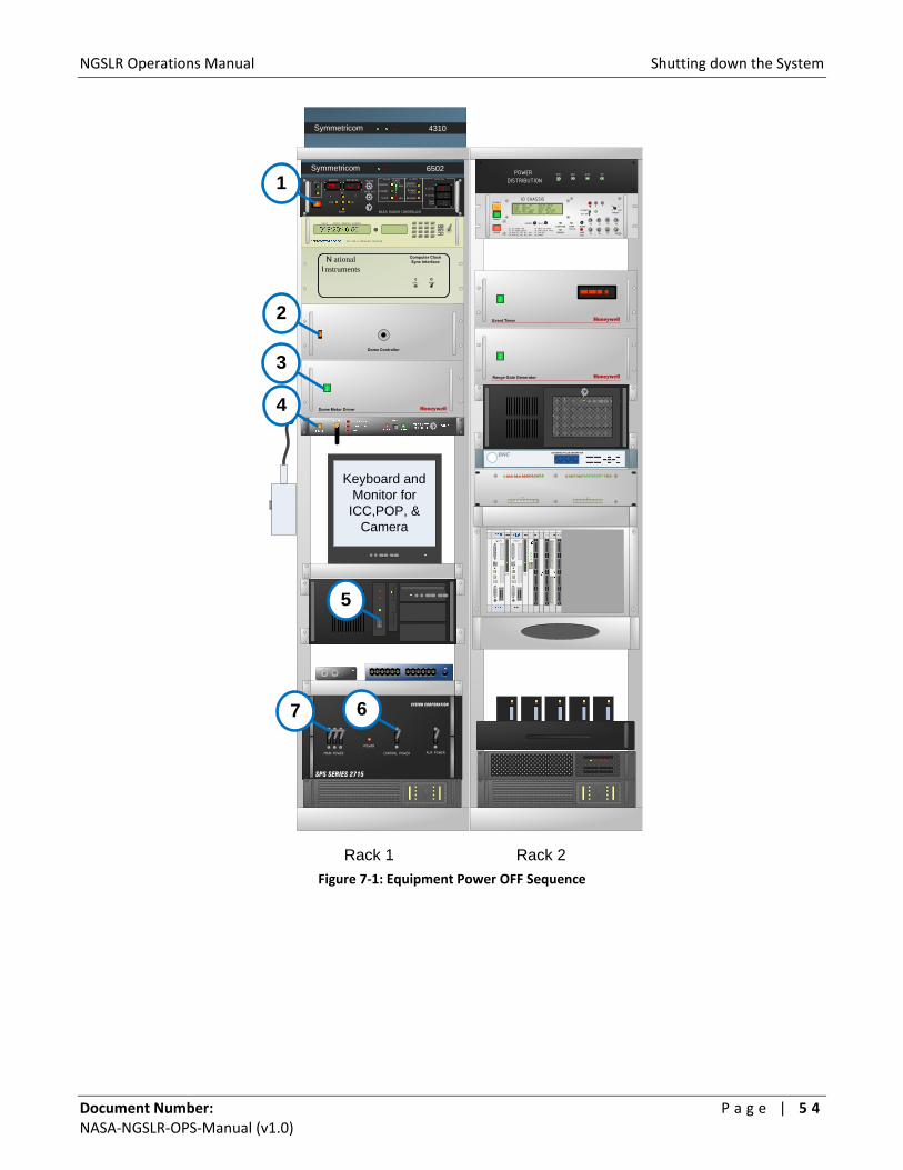
NGSLR Operations Manual Shutting down the System
Document Number: P a g e | 5 4 NASA‐NGSLR‐OPS‐Manual (v1.0)
Figure 7‐1: Equipment Power OFF Sequence
Rack 2Rack 1
IO
IO
HoneywellEvent Timer
IO
HoneywellRange Gate Generator
Dome Controller
N ationalInstruments
Computer Clock Sync Interface
IO
HoneywellDome Motor Driver
SPS SERIES 2715
XYBION CORPORATION
MAIN POWER CONTROL POWER AUX POWER
POWER
NASA RADAR CONTROLLER
TRANSMIT
STANDBY
SLAVE
AIRCRAFT DETECTED
DISABLE LASER
RECIEVER
X LEVEL
Y LEVEL
DOME TEMP
POWER LEVEL
HIGH
LOW
PEDESTALALARMSRADARTRIGGER
VIDEO OUT
DOWN
CW
UP
CCW
CNTRLELEVATIONAZIMUTH
IO
Symmetricom 6502
Keyboard and Monitor for
ICC,POP, & Camera
ENABLE
DISABLE
CNTRST. BKLT.COMPUTER
MANUAL
BEAMBLOCK
AUDIO
LAMPTEST
J1 J2 J3 J4
J5 J6 J7 J8
OPERATE
SET-UP
+ -
1
2
INT
3
TARGET
J1 ST DIODE LRO J5 28Hz LRO TRIGJ2 ST DIODE Qpeak J6 2KHz QPeak TRIGJ3 WIN #1, #2, #3, INT J7 CFD RETJ4 W/W #1, #2, #3, INT J8 SPARE
BLOCKS: 2KHZ LRO 2KHZ ND LRO NDRADAR: AIRCRAFT SELECT: 2KHZENTRY: DOOR STAIR DELAY 097.4 USECSHUTTER: MCP CAMERA HOST SAT 04 0
IO CHASSIS
POWER
DISTRIBUTION
24V 5V-12V12V
POWER
SYNC. POWER
DAYS HOURS MINUTES SECONDS
GPS TIME & FREQUENCY RECIEVER
1 2 15 1614131211109876543
P4 P3
17 18 31 32302928272625242322212019 33 341 2 15 1614131211109876543
588 SERIES PULSE GENERATORBNC
Symmetricom 4310
3
2
1
4
7 6
5
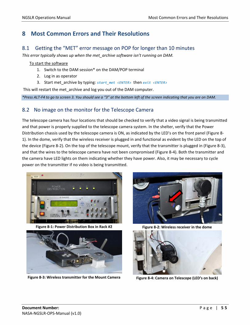
NGSLR Operations Manual Most Common Errors and Their Resolutions
Document Number: P a g e | 5 5 NASA‐NGSLR‐OPS‐Manual (v1.0)
8 Most Common Errors and Their Resolutions
8.1 Getting the “MET” error message on POP for longer than 10 minutes This error typically shows up when the met_archive software isn’t running on DAM.
To start the software
1. Switch to the DAM session* on the DAM/POP terminal
2. Log in as operator
3. Start met_archive by typing: start_met <ENTER> then exit <ENTER>
This will restart the met_archive and log you out of the DAM computer.
*Press ALT‐F4 to go to screen 3. You should see a “3” at the bottom left of the screen indicating that you are on DAM.
8.2 No image on the monitor for the Telescope Camera
The telescope camera has four locations that should be checked to verify that a video signal is being transmitted
and that power is properly supplied to the telescope camera system. In the shelter, verify that the Power
Distribution chassis used by the telescope camera is ON, as indicated by the LED’s on the front panel (Figure 8‐
1). In the dome, verify that the wireless receiver is plugged in and functional as evident by the LED on the top of
the device (Figure 8‐2). On the top of the telescope mount, verify that the transmitter is plugged in (Figure 8‐3),
and that the wires to the telescope camera have not been compromised (Figure 8‐4). Both the transmitter and
the camera have LED lights on them indicating whether they have power. Also, it may be necessary to cycle
power on the transmitter if no video is being transmitted.
Figure 8‐1: Power Distribution Box in Rack #2
Figure 8‐2: Wireless receiver in the dome
Figure 8‐3: Wireless transmitter for the Mount Camera
Figure 8‐4: Camera on Telescope (LED’s on back)
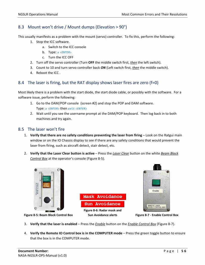
NGSLR Operations Manual Most Common Errors and Their Resolutions
Document Number: P a g e | 5 6 NASA‐NGSLR‐OPS‐Manual (v1.0)
8.3 Mount won’t drive / Mount dumps (Elevation > 90°)
This usually manifests as a problem with the mount (servo) controller. To fix this, perform the following:
1. Stop the ICC software.
a. Switch to the ICC console
b. Type: x <ENTER>
c. Turn the ICC OFF
2. Turn off the servo controller (Turn OFF the middle switch first, then the left switch).
3. Count to 10 and turn servo controller back ON (Left switch first, then the middle switch).
4. Reboot the ICC .
8.4 The laser is firing, but the RAT display shows laser fires are zero (f=0)
Most likely there is a problem with the start diode, the start diode cable, or possibly with the software. For a
software issue, perform the following:
1. Go to the DAM/POP console (screen #2) and stop the POP and DAM software.
Type: x <ENTER> then exit <ENTER>
2. Wait until you see the username prompt at the DAM/POP keyboard. Then log back in to both
machines and try again.
8.5 The laser won’t fire 1. Verify that there are no safety conditions preventing the laser from firing – Look on the Ratgui main
window or on the IO Chassis display to see if there are any safety conditions that would prevent the
laser from firing, such as aircraft detect, stair detect, etc.
2. Verify that the Laser Clear button is active – Press the Laser Clear button on the white Beam Block
Control Box at the operator’s console (Figure 8‐5).
Figure 8‐5: Beam Block Control Box
Figure 8‐6: Radar mask and
Sun Avoidance alerts
Figure 8‐7 ‐ Enable Control Box
3. Verify that the laser is enabled – Press the Enable button on the Enable Control Box (Figure 8‐7).
4. Verify the Remote IO Control box is in the COMPUTER mode – Press the green toggle button to ensure
that the box is in the COMPUTER mode.
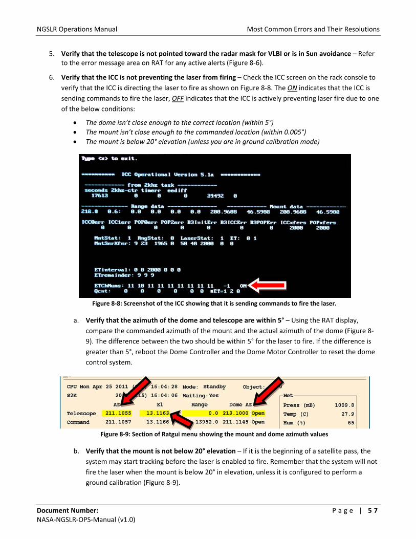
NGSLR Operations Manual Most Common Errors and Their Resolutions
Document Number: P a g e | 5 7 NASA‐NGSLR‐OPS‐Manual (v1.0)
5. Verify that the telescope is not pointed toward the radar mask for VLBI or is in Sun avoidance – Refer to the error message area on RAT for any active alerts (Figure 8‐6).
6. Verify that the ICC is not preventing the laser from firing – Check the ICC screen on the rack console to
verify that the ICC is directing the laser to fire as shown on Figure 8‐8. The ON indicates that the ICC is
sending commands to fire the laser, OFF indicates that the ICC is actively preventing laser fire due to one
of the below conditions:
The dome isn’t close enough to the correct location (within 5°)
The mount isn’t close enough to the commanded location (within 0.005°)
The mount is below 20° elevation (unless you are in ground calibration mode)
Figure 8‐8: Screenshot of the ICC showing that it is sending commands to fire the laser.
a. Verify that the azimuth of the dome and telescope are within 5° – Using the RAT display,
compare the commanded azimuth of the mount and the actual azimuth of the dome (Figure 8‐
9). The difference between the two should be within 5° for the laser to fire. If the difference is
greater than 5°, reboot the Dome Controller and the Dome Motor Controller to reset the dome
control system.
Figure 8‐9: Section of Ratgui menu showing the mount and dome azimuth values
b. Verify that the mount is not below 20° elevation – If it is the beginning of a satellite pass, the
system may start tracking before the laser is enabled to fire. Remember that the system will not
fire the laser when the mount is below 20° in elevation, unless it is configured to perform a
ground calibration (Figure 8‐9).

NGSLR Operations Manual Most Common Errors and Their Resolutions
Document Number: P a g e | 5 8 NASA‐NGSLR‐OPS‐Manual (v1.0)
c. Verify that the mount is within 0.005° to the commanded location – Check on the status of the
mount, comparing the azimuth and elevation differences on the RAT display. The mount must
be within 0.005 degrees for the laser to fire (Figure 8‐10).
Note: There is an exception for high elevation passes where the tolerance is much larger.
Figure 8‐10: Position error between the commanded and actual pointing of the telescope
7. Verify that the status of DAM is green (Figure 8‐11)
Figure 8‐11: DAM Subsystem Status
a. If the status is any color other than green, click on the status button (Figure 8‐11).
b. Search the pop‐up window for error messages regarding the motorized devices (Figure 8‐12).
Figure 8‐12: DAM Status Explanation Window
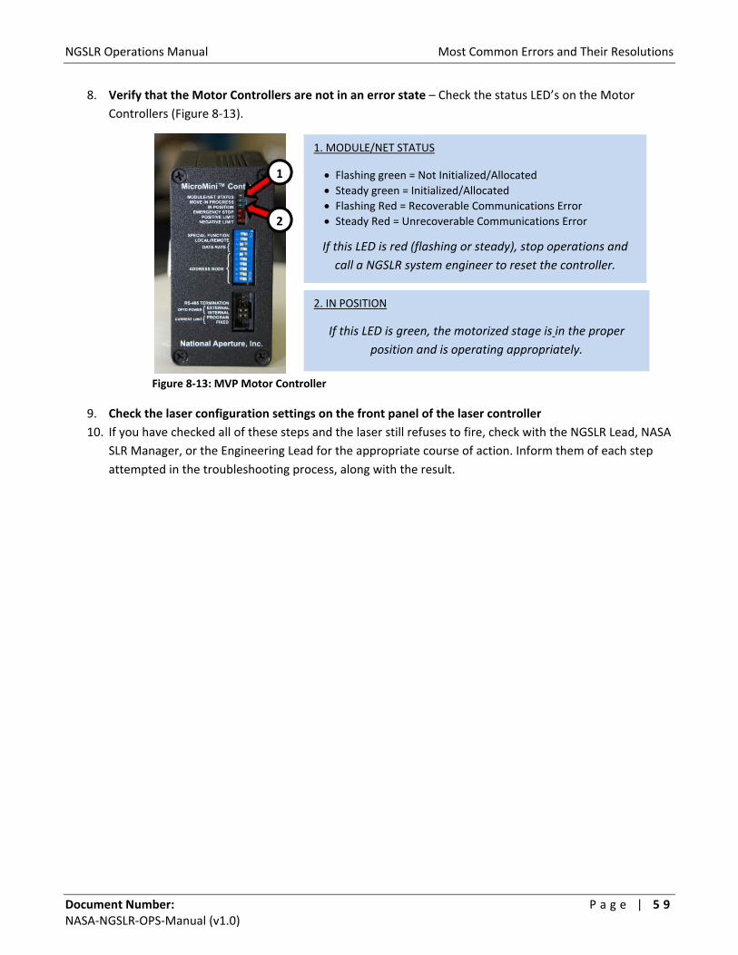
NGSLR Operations Manual Most Common Errors and Their Resolutions
Document Number: P a g e | 5 9 NASA‐NGSLR‐OPS‐Manual (v1.0)
8. Verify that the Motor Controllers are not in an error state – Check the status LED’s on the Motor
Controllers (Figure 8‐13).
Figure 8‐13: MVP Motor Controller
9. Check the laser configuration settings on the front panel of the laser controller
10. If you have checked all of these steps and the laser still refuses to fire, check with the NGSLR Lead, NASA
SLR Manager, or the Engineering Lead for the appropriate course of action. Inform them of each step
attempted in the troubleshooting process, along with the result.
1. MODULE/NET STATUS
Flashing green = Not Initialized/Allocated Steady green = Initialized/Allocated Flashing Red = Recoverable Communications Error
Steady Red = Unrecoverable Communications Error
If this LED is red (flashing or steady), stop operations and
call a NGSLR system engineer to reset the controller.
2. IN POSITION
If this LED is green, the motorized stage is in the proper
position and is operating appropriately.
1
2
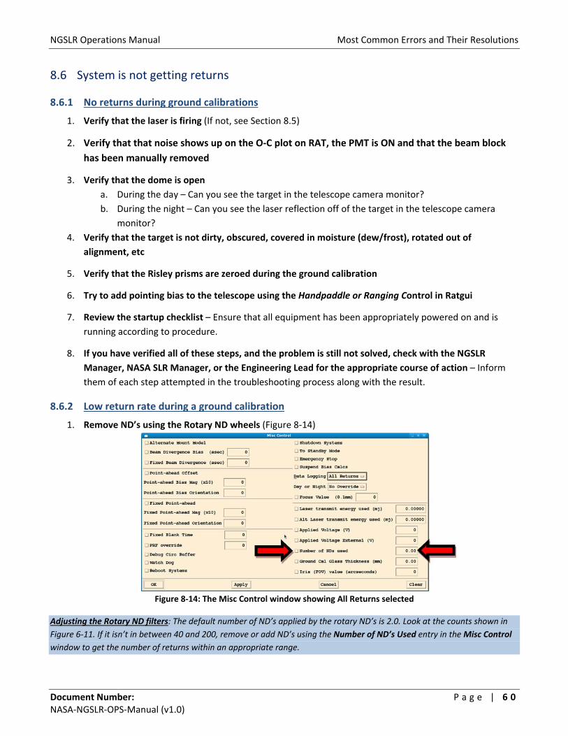
NGSLR Operations Manual Most Common Errors and Their Resolutions
Document Number: P a g e | 6 0 NASA‐NGSLR‐OPS‐Manual (v1.0)
8.6 System is not getting returns
8.6.1 No returns during ground calibrations
1. Verify that the laser is firing (If not, see Section 8.5)
2. Verify that that noise shows up on the O‐C plot on RAT, the PMT is ON and that the beam block
has been manually removed
3. Verify that the dome is open
a. During the day – Can you see the target in the telescope camera monitor?
b. During the night – Can you see the laser reflection off of the target in the telescope camera
monitor?
4. Verify that the target is not dirty, obscured, covered in moisture (dew/frost), rotated out of
alignment, etc
5. Verify that the Risley prisms are zeroed during the ground calibration
6. Try to add pointing bias to the telescope using the Handpaddle or Ranging Control in Ratgui
7. Review the startup checklist – Ensure that all equipment has been appropriately powered on and is
running according to procedure.
8. If you have verified all of these steps, and the problem is still not solved, check with the NGSLR
Manager, NASA SLR Manager, or the Engineering Lead for the appropriate course of action – Inform
them of each step attempted in the troubleshooting process along with the result.
8.6.2 Low return rate during a ground calibration
1. Remove ND’s using the Rotary ND wheels (Figure 8‐14)
Figure 8‐14: The Misc Control window showing All Returns selected
Adjusting the Rotary ND filters: The default number of ND’s applied by the rotary ND’s is 2.0. Look at the counts shown in
Figure 6‐11. If it isn’t in between 40 and 200, remove or add ND’s using the Number of ND’s Used entry in the Misc Control
window to get the number of returns within an appropriate range.
NGSLR Operations Manual Most Common Errors and Their Resolutions
Document Number: P a g e | 6 1 NASA‐NGSLR‐OPS‐Manual (v1.0)
8.6.3 No returns during satellite tracking
1. Ensure that the laser is firing (If not, see Section 8.5)
2. Verify the PMT beam block has been manually removed
3. Check sky conditions to verify that clouds are not blocking the signal
4. Verify that the PMT is ON and that noise shows up on the O‐C plot on RAT
5. Verify that the dome is open
a. During the day – Can you see the target in the telescope camera monitor?
b. During the night – Can you see the laser reflection off of the target in the telescope camera
monitor?
6. Add pointing bias to the telescope
7. Verify that the meteorological data is being logged properly – Values for the pressure, temperature,
wind speed, etc. should all be within normal ranges.
8.7 The software appears to have crashed/is non‐responsive
If the POP software stops unexpectedly, especially when it declares a “segmentation fault,” then chances are
that you will need to reboot the system. If the system responds to keyboard input, perform a soft reboot. See
the section How to do a soft reboot on POP for more information. Please note that you will also need to reboot
the RAT laptop computer after you have rebooted POP.
If the DAM/POP terminal is unresponsive to keyboard input, you will need to perform a hard reboot. Note:
Performing a hard reboot may affect both POP and DAM. See the section How to do a hard reboot on POP and
How to do a hard reboot on DAM for more details.
If both POP and DAM are rebooted you should re‐mount the disk drives on both of these machines. See
Remounting the disk drives on POP and DAM.
8.7.1 How to do a soft reboot on POP
POP must be rebooted using the rack mounted keyboard.
1. Switch to POP using the labeled button on the KVM and type: reset <ENTER>
2. When asked for the password, use the operator password – The computer should automatically
reboot and display the username prompt on the screen.
3. Follow normal login procedures from this point
Note: Whenever POP is rebooted, you must also reboot RAT. See How to do a soft reboot on RAT.

NGSLR Operations Manual Most Common Errors and Their Resolutions
Document Number: P a g e | 6 2 NASA‐NGSLR‐OPS‐Manual (v1.0)
8.7.2 How to do a hard reboot on POP
Only perform a hard reboot of POP if all else has failed,
you have been trained on the procedure, and you have
been approved by the NASA SLR Lead! Note that
whenever the POP computer is rebooted, you must also
perform a hard reboot on RAT. This process takes
approximately 15 minutes to complete and should only
be used as a last resort.
1. Use the “reboot tool” to press the recessed button labeled
“RST” on the front of the POP computer (Figure 8‐15).
Make sure you select the correct computer and don’t
accidentally reset DAM. The POP computer will go through
several file system checks, which may prove to be a lengthy
process.
2. Once the login screen comes up, login and follow normal operating procedures from this point.
8.7.3 How to do a soft reboot on DAM
If the DAM status color goes orange or white (see Appendix C) and
remains that color for more than 5 minutes, then DAM needs to be
rebooted. DAM must be rebooted using the DAM/POP terminal.
You should see a “3” at the bottom left of the screen indicating that you are on DAM. If not, press ALT‐F4 to go
to the DAM computer.
1. Type: reset <ENTER>
2. When asked for the password, use the operator password. The computer should automatically reboot
and display the username prompt on the screen.
3. Log in and start met_archive by typing in: start_met <ENTER>, then exit <ENTER>
4. Follow normal procedures from this point.
8.7.4 How to do a hard reboot on DAM
Only perform a hard reboot of the DAM computer if all else has failed, you have been trained on the
procedure, and you have been approved by the NASA SLR Lead! This process takes approximately 15
minutes to complete and should only be used as a last resort.
If the keyboard is unresponsive on the DAM/POP terminal, or the soft reboot hangs, you will need to do a hard
reboot of the DAM computer. Use the “reboot tool” to press the recessed button labeled “RST” (Figure 8‐15) on
the front of the DAM computer. Make sure you select the correct computer and don’t accidentally reset POP.
Figure 8‐15: The reboot button is located at a
similar location on the POP and DAM computers

NGSLR Operations Manual Most Common Errors and Their Resolutions
Document Number: P a g e | 6 3 NASA‐NGSLR‐OPS‐Manual (v1.0)
The DAM computer will go through several file system checks, which may prove to be a lengthy process. Log
into DAM using the DAM/POP terminal. You should see a “3” at the bottom left of the screen indicating that you
are on DAM. If not, press ALT‐F3 to go to the DAM computer.
1. Log in and start met_archive by typing in: start_met <ENTER>, then exit <ENTER>
2. Follow normal procedures from this point.
8.7.5 Remounting the disk drives on POP and DAM
If both POP and DAM are rebooted you should re‐mount the disk drives on both of these machines.
1. On POP, after logging in as operator type: /mount_DANdirs<ENTER>
The response will be either the mounting of the disks or error messages saying the “…resource is busy.” Regardless of the
message, the result will ensure the mounting of the disks.
2. On the DAM/POP console switch to screen 3 (Alt‐F4)
3. Log in as operator
4. Type: /mount_popdirs <ENTER>
8.7.6 How to do a soft reboot on RAT
1. On the RAT laptop, exit out of the RAT software by selecting FILE → EXIT.
2. Under the SYSTEM menu at the top left of the laptop screen, select SHUTDOWN.
3. When the pop‐up menu gives you a selection of what to do, select RESTART.
4. Follow the startup instructions included in Section 2 of this document.
8.7.7 How to do a hard reboot on RAT
1. Press and hold the power button on the RAT laptop until the system reboots
2. Follow the normal login and startup procedures for RAT
Note: These the drives should be mounted on both POP and DAM before starting prior to starting MET_ARCHIVE.
8.7.8 How to do a soft reboot on the Camera Computer
To reboot the computer, close all open programs and windows, click the START button in the lower left corner of
the screen, and select Shut Down (Figure 8‐16).
Figure 8‐16: Start and Shut Down buttons
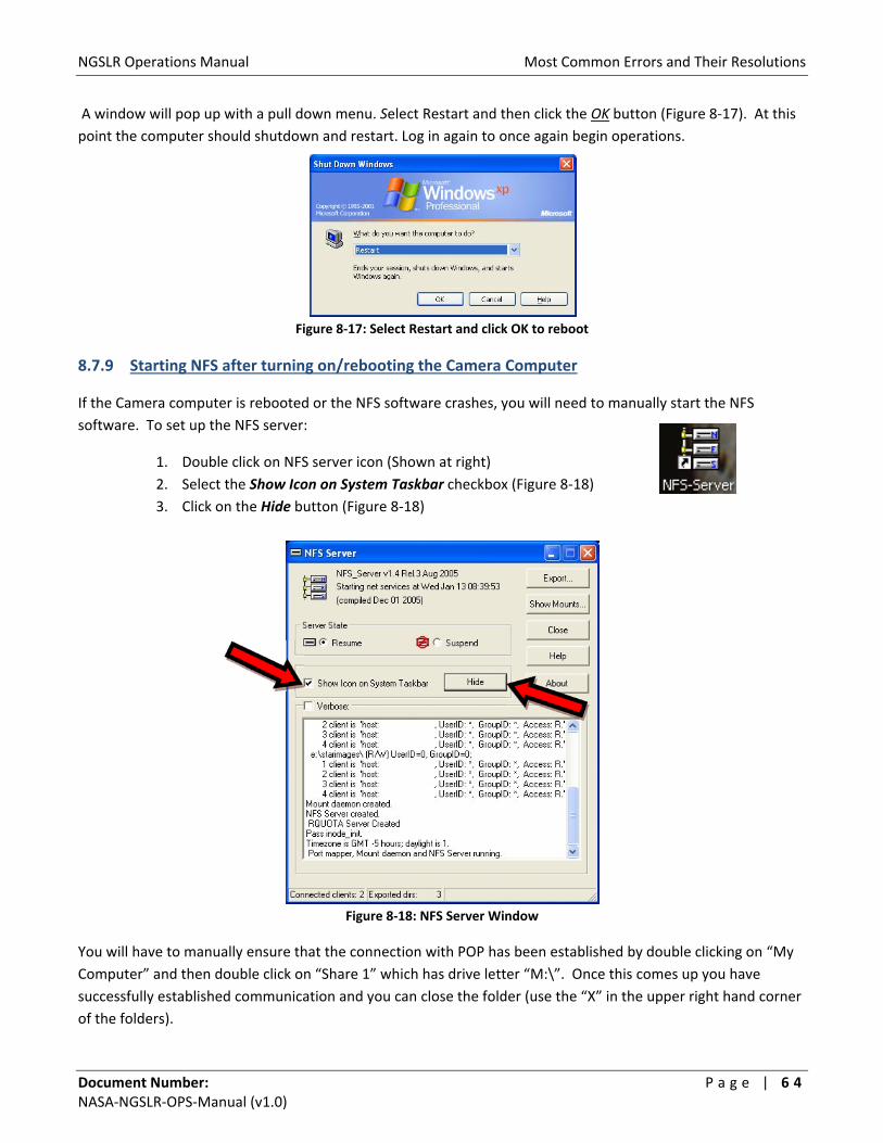
NGSLR Operations Manual Most Common Errors and Their Resolutions
Document Number: P a g e | 6 4 NASA‐NGSLR‐OPS‐Manual (v1.0)
A window will pop up with a pull down menu. Select Restart and then click the OK button (Figure 8‐17). At this
point the computer should shutdown and restart. Log in again to once again begin operations.
Figure 8‐17: Select Restart and click OK to reboot
8.7.9 Starting NFS after turning on/rebooting the Camera Computer
If the Camera computer is rebooted or the NFS software crashes, you will need to manually start the NFS
software. To set up the NFS server:
1. Double click on NFS server icon (Shown at right)
2. Select the Show Icon on System Taskbar checkbox (Figure 8‐18)
3. Click on the Hide button (Figure 8‐18)
Figure 8‐18: NFS Server Window
You will have to manually ensure that the connection with POP has been established by double clicking on “My
Computer” and then double click on “Share 1” which has drive letter “M:\”. Once this comes up you have
successfully established communication and you can close the folder (use the “X” in the upper right hand corner
of the folders).

NGSLR Operations Manual Most Common Errors and Their Resolutions
Document Number: P a g e | 6 5 NASA‐NGSLR‐OPS‐Manual (v1.0)
8.8 Event Timer Resets
Occasional resets of the Event Timer should not pose a problem, though if they occur with increasing frequency,
they may allude to high noise rates being received by the system. If this is the case, verify that the iris and the
band pass filter are set correctly for the conditions.
If the receiver is flooded with returns, which means ~4000 events/sec or greater, then it won’t be able to keep
up, and will end up being reset.
8.8.1 Event Timer Continually Resets
If the 1 PPS is disconnected from the Event Timer, or it is receiving a bad signal, it can cause the Event Timer to
continually reset. Verify that the 1 PPS cable is connected, and that the Event Timer is getting a good 1 PPS
signal.
This is critical because the ICC checks synchronization by verifying that the delay between the 1 PPS signal and
the 2 kHz on‐time is 9.8 μs in length. If the ICC sees several delays that do not match this, it determines that it is
out of sync, and a reset of the Event Timer is necessary. Hence, if there is no 1 PPS, the signal is erratic, or it is
from a source other than the True Time XL‐DC, the ICC will continually assume that it is out of synch with Event
Timer.

NGSLR Operations Manual Most Common Errors and Their Resolutions
Document Number: P a g e | 6 6 NASA‐NGSLR‐OPS‐Manual (v1.0)
8.9 Dome won’t open or close
This could be caused by a failure of the electronics, solar panel, or battery. In these cases, an external power
supply can be used to open and close the dome.
1. Connect AC power to the dome auxiliary power box. Note that the receptacle is a GFI and the AC input
on the power box contains an ON/OFF switch.
2. Next, connect the two position circular connector to the power box. The other end (yellow plug)
connects to the covered “outlet” next to the toggle switch.
3. In normal operation, the toggle switch should be on “BATTERY POWER” . Flip the switch up to
“EXTERNAL POWER”.
4. Use the toggle switch on the power box to select “OPEN” or “CLOSED”.
See the Dome Shutter Control Manual for more details and pictures.

NGSLR Operations Manual Appendix A: Acronyms
Document Number: P a g e | 6 7 NASA‐NGSLR‐OPS‐Manual (v1.0)
Appendix
Appendix A: Acronyms
Acronym Definition AC Alternating Current
ANSI American National Standards Institute
FAA Federal Aviation Administration
GFI Ground Fault Interrupter
GGAO Goddard Geophysical and Astronomical Observatory
GPS Global Positioning System
ILRS International Laser Ranging Service
IOC IO Chassis
LAGEOS Laser Geodynamics Satellite
LHRS Laser Hazard Reduction System
LOA Laser Operations Area
LRO Lunar Reconnaissance Orbiter
LSO Laser Safety Office
MCP Micro‐Channel Plate
MINICO Mini‐Collocation
NCRCC National Capital Region Coordination Center
ND Neutral Density
NFS Network File System
NGSLR Next Generation Satellite Laser Ranging
NIM Nuclear Instrumentation Module/Method
OD Optical Density
PMT Photo Multiplier Tube
PPS Pulse Per Second
RF Radio Frequency
RMS Root Mean Square
SLR Satellite Laser Ranging
VLBI Very Long Baseline Interferometry
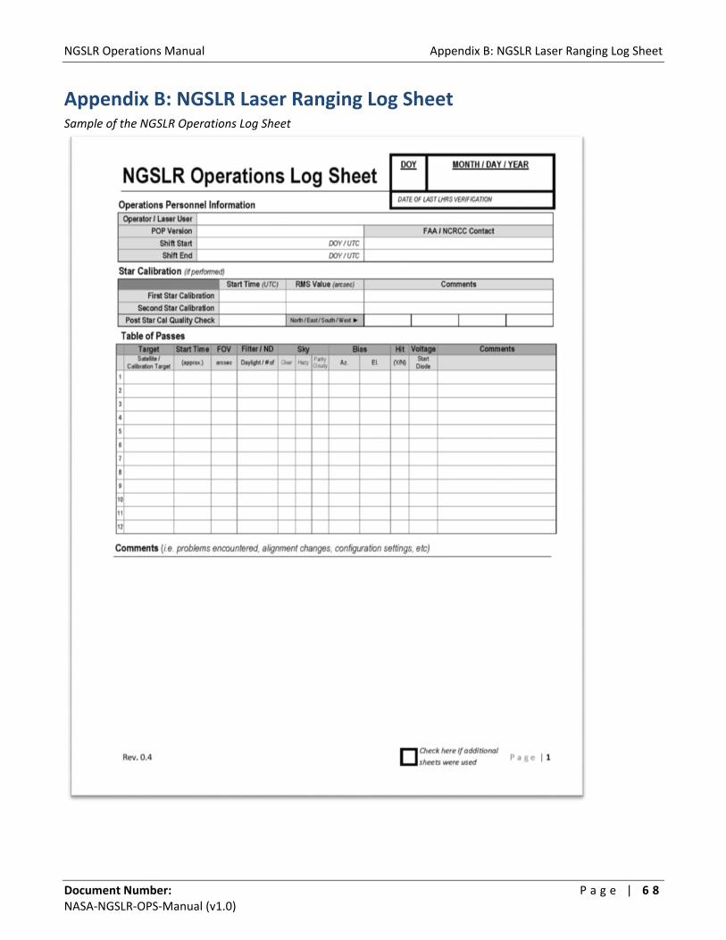
NGSLR Operations Manual Appendix B: NGSLR Laser Ranging Log Sheet
Document Number: P a g e | 6 8 NASA‐NGSLR‐OPS‐Manual (v1.0)
Appendix B: NGSLR Laser Ranging Log Sheet Sample of the NGSLR Operations Log Sheet

NGSLR Operations Manual Appendix C: Alert statuses
Document Number: P a g e | 6 9 NASA‐NGSLR‐OPS‐Manual (v1.0)
Appendix C: Alert statuses See the NGSLR Software manual for more details on status message alerts.
Subsystem Status Color TableDescription
white Computer or subsystem not turned on
green OK
Below colors indicate that the system is not OK, listed in order of severity (mild to most severe)
yellow Alert
orange Warning
red Severe
black Most Severe
Color

NGSLR Operations Manual Appendix D: Measuring the Laser Power
Document Number: P a g e | 7 0 NASA‐NGSLR‐OPS‐Manual (v1.0)
Appendix D: Measuring the Laser Power SLR laser pulse measurements must be made once per shift, typically at the beginning of the shift.
1. Turn the power meter on using the toggle switch on the back of the device (Figure D‐1)
Figure D‐1: Power Energy Meter
Figure D‐2: Manual Insertion Mirror (horizontal)
2. Close the laser curtain and put on protective eyewear
3. Flip the Manual Insertion Mirror for the power meter into the vertical position (Figure D‐2)
Warning: Close the laser curtain and put on protective eyewear before turning on the laser.
Inform all present that the laser is being turned on. Minimum eyewear optical density for the
SLR laser is >4.7 ND @ 532nm. Failure to follow these guidelines can result in severe eye
damage to anyone exposed to the beam.
Warning: Keep hands and arms away from the transmitted beam at all times. At no point in
this procedure should the operator adjust any optical device while the laser is ON. Remove any
reflective/shiny jewelry before entering the Laser Operations Area.
4. Turn on the SLR laser and set emission levels to tracking power
(Figure D‐3)
5. Go to the front panel of the SLR laser controller and change
triggering to INTERNAL
a. Press the Menu button on the laser driver.
b. Under Pulse Settings, set Trigger to INT.
Figure D‐3: PI laser Interface at
Tracking Power
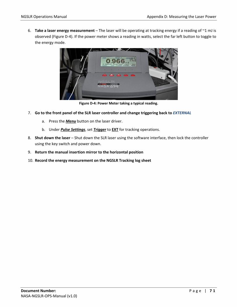
NGSLR Operations Manual Appendix D: Measuring the Laser Power
Document Number: P a g e | 7 1 NASA‐NGSLR‐OPS‐Manual (v1.0)
6. Take a laser energy measurement – The laser will be operating at tracking energy if a reading of ~1 mJ is
observed (Figure D‐4). If the power meter shows a reading in watts, select the far left button to toggle to
the energy mode.
Figure D‐4: Power Meter taking a typical reading.
7. Go to the front panel of the SLR laser controller and change triggering back to EXTERNAL
a. Press the Menu button on the laser driver.
b. Under Pulse Settings, set Trigger to EXT for tracking operations.
8. Shut down the laser – Shut down the SLR laser using the software interface, then lock the controller
using the key switch and power down.
9. Return the manual insertion mirror to the horizontal position
10. Record the energy measurement on the NGSLR Tracking log sheet

NGSLR Operations Manual Appendix E: Measuring the Start Diode Voltage
Document Number: P a g e | 7 2 NASA‐NGSLR‐OPS‐Manual (v1.0)
Appendix E: Measuring the Start Diode Voltage During a tracking shift, it is necessary to monitor the start diode voltage. Follow the below steps to complete the
measurement.
Warning: Close the laser curtain and put on protective eyewear before turning on the laser.
Inform all present that the laser is being turned on. Minimum eyewear optical density for the
SLR laser is >4.7 ND @ 532nm. Failure to follow these guidelines can result in severe eye
damage to anyone exposed to the beam.
Warning: Keep hands and arms away from the transmitted beam at all times. At no point in
this procedure should the operator adjust any optical device while the laser is ON. Remove any
reflective/shiny jewelry before entering the Laser Operations Area.
1. Turn ON the oscilloscope
2. Verify start diode connectivity – Check the connection
between the directional coupler and the oscilloscope
(Figure E‐1).
3. With the laser firing, take a measurement – Adjust the
trigger level on the oscilloscope as needed to obtain an
accurate reading. The voltage should be ~240 mV
(Figure E‐2).
4. Record the measurement on the log sheet
5. Turn OFF the Oscilloscope
Figure E‐2: Sample Start Diode Oscilloscope Image
If the start diode voltage is not at the
appropriate level, ensure that the laser is
fully warmed up (20‐30 minutes) before
making any adjustments to the start diode
attenuator.
Figure E‐1: Arrow on the directional coupler
shows the port used to send the signal to the
oscilloscope