NGS Updates - geodesy.noaa.gov · depend on leveling results as well as gravity. ... •Observe GPS...
52
NGS Updates MSPS Surveyors’ Conference Dave Zenk NGS Advisor February 21, 2014
Transcript of NGS Updates - geodesy.noaa.gov · depend on leveling results as well as gravity. ... •Observe GPS...

NGS Updates MSPS Surveyors’ Conference
Dave Zenk
NGS Advisor
February 21, 2014

NGS Activities
• OPUS
• GRAV-D
• Geoid Slope Validation Survey in Iowa
• MN Level Network Remediation

OPUS SUITE
• OPUS Suite has several services
– OPUS STATIC (OPUS-S)
– OPUS RAPID STATIC (OPUS-RS)
– OPUS DATABASE (OPUS-DB)
– OPUS PROJECTS (OPUS-P)

OPUS STATIC
• 2 hours to 48 hours occupation time, dual frequency receiver.
• Choose OPTIONS to control some aspects of how OPUS will compute your solution

OPUS STATIC
• OPUS Submission Page
Step 1
Step 2
Step 3
Step 4
Step 5
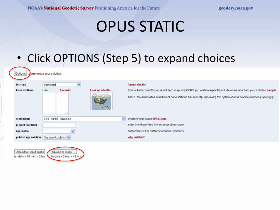
OPUS STATIC
• Click OPTIONS (Step 5) to expand choices

OPUS STATIC
• Click UPLOAD to STATIC
• You will receive your solution by email in about 5 minutes.
• Solution is the average of 3 baselines to nearby CORS stations.
• Single Occupation – no check.
• Multiple Occupations - each computed as standalone – you must compare them.

OPUS RAPID STATIC
• 15 minutes to 2 hours of dual frequency data
• Like OPUS STATIC, you submit the file via the OPUS Submission Page.
• Click OPTIONS to expand choices
• Click UPLOAD to RAPID STATIC
• You will receive your solution by email in about 10 minutes.
• Solution is the least squares adjustment (not simple average) of baselines to up to 9 nearby CORS stations
• Single and/or Multiple Occupations – you compare.
OPUS DATABASE
• OPUS-DB is a service that allows users to voluntarily “share” their OPUS solution with the public.
• Service is open to all – no special training.
• Requires a single 4 hour occupation, a mark description, and 2 photographs.
• Gateway is via OPUS Submission page
– http://www.ngs.noaa.gov/OPUS/

OPUS DATABASE

OPUS DATABASE
• Once you say YES and submit, you will receive an email that asks you whether you want to share and, if so, to approve the solution shown.
• After you agree to share and you approve the solution – NGS personnel will review the solution for any obvious problems and allow it for inclusion in OPUS-DB.
• Note that your name and organization will be shared for others to contact you for more information

OPUS DATABASE
• Reasons to SHARE your solution:
– Some agencies require you to do so (by contract)
– Encourages use of shared control marks by fellow surveyors
– NGS will use the ellipsoid height to improve future geoid models (GPS on BM)
OPUS DATABASE
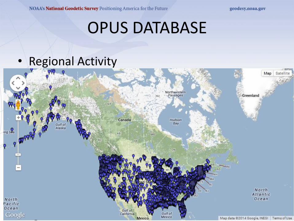
• Regional Activity

OPUS DATABASE
• Local Activity

OPUS DATABASE
• Sample shared mark solution for BARB RESET

OPUS DATABASE
• Note that sharing a solution via OPUS-DB is not a datasheet but a shared mark solution. As such, NGS will adopt the use of the following definitions: – Share: The act of a user releasing to NGS the observations (via OPUS or OPUS
Projects), metadata and results of geodetic surveys tied to the NSRS for public dissemination.
– Publish: The action of NGS providing to the public, the official, National Spatial Reference System (NSRS) time-dependent geodetic coordinates set on a mark.
– Submit: The act of a user releasing to NGS the observations, metadata and results of geodetic surveys tied to the NSRS for the express purpose of the NGS evaluating the survey and publishing if appropriate.
– Datasheet: A report containing the published NSRS time dependent coordinates on a mark, as well as subsidiary information and metadata such as superseded coordinates, descriptions and recovery history of the mark.

OPUS PROJECTS
• OPUS PROJECTS is a newly operational service that extends the OPUS suite in a powerful new way.
• OPUS-P allows trained users to submit multiple data files on multiple marks in a project.
• OPUS-P assigns each file to a session based on logical methods.
• User makes decisions on how to process each session, how to adjust the project, and whether to Bluebook the results.
• All web-based, nothing to install.


OPUS PROJECTS
• OPUS-P advantages:
– Field crew can submit RINEX data at end of day via OPUS interface.
– Project Manager can see data and watch progress via web login.
– Party Chief can process daily sessions to determine if re-observations are needed.
– OPUS-P produces Bluebook (B and G) files for optional Bluebook submissions.

OPUS PROJECTS
• OPUS-P advantages:
– Provides independent solution to compare to your existing software.
– Solutions and adjustments are true least squares analysis.
– Highly automated handling of CORS data.

OPUS PROJECTS
• OPUS-P requires training to become authorized user.
– Local Advisor can deliver training.
– Check NGS Corbin Training Center for schedule or call Advisor.
– In-person, 2 days, includes time to practice.
• I will offer OPUS-P training several times this year.

GRAV-D
• NGS has embarked on a long-term project to measure the Earth’s gravity field over all 50 states, the Great Lakes, and nearby oceans to produce a GEOID that is accurate to 2 cm.
• This GEOID will allow NGS to define an orthometric height system based on gravity and fully compatible with GPS.

GRAV-D
• Current GEOID models are hybrid models and depend on leveling results as well as gravity.
• Errors in leveling and assumptions made in NAVD88 have been proven to yield an orthometric height system that does not agree with known gravity field of the Earth.
• Water still runs downhill of course, but there are at least 2 problems from a national perspective.
GRAV-D
• 1) Heights in the CONUS cannot be compared to heights on islands (Hawaii, Puerto Rico, etc)
– Islands all have their own datums!
• 2) There is about 1 meter of height discrepancy when comparing NAVD88 heights to what the gravity field alone would indicate.

GRAV-D

GRAV-D
• NGS has flown data gathering missions over the Gulf Coast, Alaska, Great Lakes (includes MN and WI).
• Operations will continue over coastal zones, then over the interior of the USA.
• Expect to take several more years.
– Only 1 airborne gravity meter available.
• New GEOID model will coincide with new 3D North American Datum in (fill-in date here).
GRAV-D
• Complete information about GRAV-D can be found at:
– http://www.ngs.noaa.gov/GRAV-D/index.shtml
– http://www.ngs.noaa.gov/GRAV-D/pubs/GRAV-D_v2007_12_19.pdf
GRAV-D
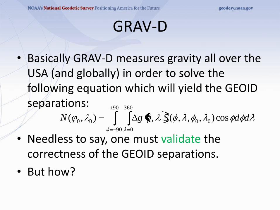
• Basically GRAV-D measures gravity all over the USA (and globally) in order to solve the following equation which will yield the GEOID separations:
• Needless to say, one must validate the correctness of the GEOID separations.
• But how?
ddSgN cos),,,(,),( 00
90
90
360
0
00

GRAV-D
• In order to validate the results of the project, NGS is embarked on a series of Geoid Slope Validation Surveys (GSVS)
• 1 in Texas (GSVS11)
• 1 in Iowa (GSVS14)
• 1 in a mountainous region to be named later.

GSVS14
• Geoid Slope Validation Survey
• Iowa along US 30 from Sioux City to Cedar Falls
• What does it validate?
GEOID Surface
ELLIPSOID Surface
How do we measure slopes?
GSVS14
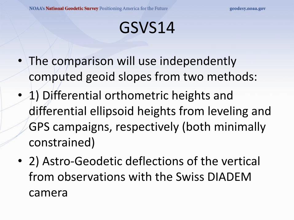
• The comparison will use independently computed geoid slopes from two methods:
• 1) Differential orthometric heights and differential ellipsoid heights from leveling and GPS campaigns, respectively (both minimally constrained)
• 2) Astro-Geodetic deflections of the vertical from observations with the Swiss DIADEM camera

GSVS14
• Observe GPS positions at A and B to obtain
– Ellipsoid distance between A and B
– Ellipsoid heights at A and B (green)
• Also observe, by leveling, the Orthometric heights
– Subtract to get orthometric heights (red)
• Difference = GEOID separations at A and B (blue)
GEOID Surface
ELLIPSOID Surface
GROUND Surface B A

GSVS14
• Then compute the geoid slope (blue dash)
– subtract the geoid separations at A and B,
– then divide by the distance from A to B.
GEOID Surface
ELLIPSOID Surface
GROUND Surface B A

GSVS14
• Deflection of the Vertical
– Angular difference in arcseconds between
• Line perpendicular to the ellipsoid and
• Line perpendicular to the geoid
GEOID Surface
ELLIPSOID Surface
GROUND Surface B A

GSVS14
• The angular difference can be measured by
– Performing a series of astronomic (star) observations which yield the astronomic latitude and longitude (which are influenced by local gravity)
– Comparing to the geodetic latitude and longitude which are based on ellipsoidal computations.
• Use a telescope, or better yet, a digital camera

GSVS14
• DIADEM Camera
• Dave with Wild T-3
• Wild T-4
GSVS14
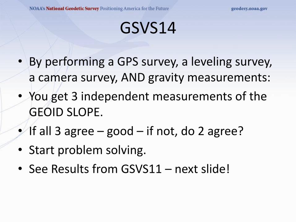
• By performing a GPS survey, a leveling survey, a camera survey, AND gravity measurements:
• You get 3 independent measurements of the GEOID SLOPE.
• If all 3 agree – good – if not, do 2 agree?
• Start problem solving.
• See Results from GSVS11 – next slide!

Results of GSVS11
0
0.5
1
1.5
2
2.5
3
3.5
RM
S Er
rors
(cm
)
Distances between points (km)
Predicted Errors of various geoid models over GSVS11 after removal of GPS/Leveling error budget
USGG2009
EGM2008
xEGM-G
xEGM-GA
xUSGG-GA-R-K480
The “1 cm geoid”

MN Level Network Remediation
• The MN Level Network is statewide, densely spaced, and is known to have some problems.
• Known problems include:
– Aging infrastructure (over 30 years)
– Disconnected networks (orphans)
– Leveling lines that failed to connect at crossings
– Leveling lines that are spurs that could be extended to close nearby loops
– Areas of large residuals
– Areas of large elevation discrepancies

MN Level Network Remediation
• In order to efficiently locate and correct areas that need remedial attention, MNDOT hired a student worker for Summer 2013.
• She created multi-county networks that could be adjusted and analyzed.
• She located many orphans, spurs, and crossovers – all of which are being remediated.

MN Level Network Remediation
• Her adjustment showed where the published elevation did not match the adjusted elevation.
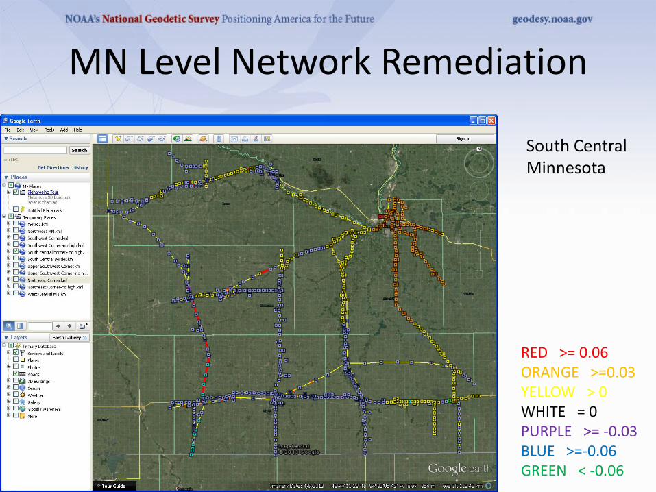
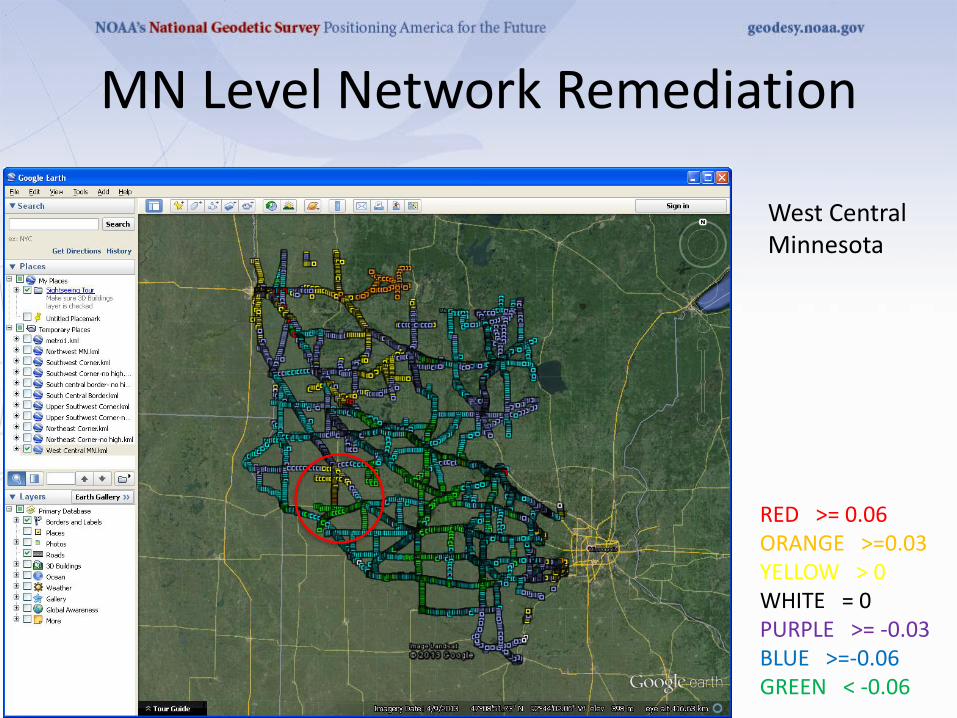
• She created a series of impressive maps which show areas of these large elevation changes in color.
RED >= 0.06 ORANGE >=0.03 YELLOW > 0 WHITE = 0 (Fixed Points) PURPLE >= -0.03 BLUE >=-0.06 GREEN < -0.06

MN Level Network Remediation
• In a perfect adjustment, the colors would be expected to shade smoothly from one to the next.
– Like a rainbow-type pattern.
– No color sequence jumps.
RED >= 0.06 ORANGE >=0.03 YELLOW > 0 WHITE = 0 PURPLE >= -0.03 BLUE >=-0.06 GREEN < -0.06
MN Level Network Remediation
South Central Minnesota
RED >= 0.06 ORANGE >=0.03 YELLOW > 0 WHITE = 0 PURPLE >= -0.03 BLUE >=-0.06 GREEN < -0.06
MN Level Network Remediation
RED >= 0.06 ORANGE >=0.03 YELLOW > 0 WHITE = 0 PURPLE >= -0.03 BLUE >=-0.06 GREEN < -0.06
West Central Minnesota

MN Level Network Remediation
West Central Minnesota near Swift County
RED >= 0.06 ORANGE >=0.03 YELLOW > 0 WHITE = 0 PURPLE >= -0.03 BLUE >=-0.06 GREEN < -0.06

MN Level Network Remediation
RED >= 0.06 ORANGE >=0.03 YELLOW > 0 WHITE = 0 PURPLE >= -0.03 BLUE >=-0.06 GREEN < -0.06
West Central Minnesota in Swift County

MN Level Network Remediation
Northwest Minnesota
RED >= 0.06 ORANGE >=0.03 YELLOW > 0 WHITE = 0 PURPLE >= -0.03 BLUE >=-0.06 GREEN < -0.06

MN Level Network Remediation
Southern Minnesota
RED >= 0.06 ORANGE >=0.03 YELLOW > 0 WHITE = 0 PURPLE >= -0.03 BLUE >=-0.06 GREEN < -0.06

MN Level Network Remediation
• NGS will not readjust the MN Level Net until the new 3D Datum is released in (pick a year).
• Until then MNDOT will continue to address known areas of concern by
– performing new leveling,
– adjusting multi-county areas,
– submitting the work to NGS,
– and monitoring for improvement.
Cumulative Impact of Activities
• All of the activities in this presentation have a single goal:
– To provide products that the public can use to efficiently and accurately obtain horizontal and vertical positions.
• The next slide shows the fruitful impact of these activities.
• GPS-derived orthometric heights at 95% is:
+/- 2 cm, (not +/- 4 cm)
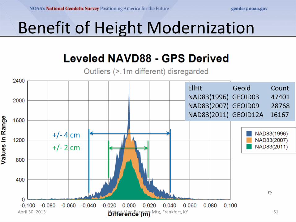
Benefit of Height Modernization
EllHt Geoid Count NAD83(1996) GEOID03 47401 NAD83(2007) GEOID09 28768 NAD83(2011) GEOID12A 16167
Natl Ht Mod Partners Mtg, Frankfort, KY April 30, 2013 51
+/- 4 cm
+/- 2 cm

The End
• Questions