Touch Panel Leveling Control Four-Point Air Leveling With ... · PDF fileHWH...
23
DUMP LEVEL AIR HWH COMPUTERIZED LEVELING UNDERSTAND OPERATOR’S MANUAL BEFORE USING. BLOCK FRAME AND TIRES SECURELY BEFORE REMOVING TIRES OR CRAWLING UNDER VEHICLE. EXCESS SLOPE NOT IN PARK/ TRAVEL OFF CAUTION! RAISE SERVICE MANUAL BRAKE HWH COMPUTER-CONTROLLED 600 SERIES LEVELING SYSTEM Touch Panel Leveling Control With Tag Dump Four-Point Air Leveling www.hwh.com Ph: 800/321-3494 (or) 563/724-3396 | Fax: 563/724-3408 2096 Moscow Road | Moscow, Iowa 52760 (On I-80, Exit 267 South) HWH CORPORATION FEATURING: R CORPORATION W H R H ML19048/MI91.0015 06MAY04
Transcript of Touch Panel Leveling Control Four-Point Air Leveling With ... · PDF fileHWH...

DUMP
LEVEL AIR
HWH COMPUTERIZED LEVELING
UNDERSTAND OPERATOR’S MANUAL BEFORE USING. BLOCK FRAME AND TIRESSECURELY BEFORE REMOVING TIRES OR CRAWLING UNDER VEHICLE.
EXCESSSLOPE
NOT INPARK/
TRAVELOFF
CAUTION!RAISE
SERVICE MANUAL
BRAKE
HWH COMPUTER-CONTROLLED600 SERIES LEVELING SYSTEM
Touch Panel Leveling Control
With Tag DumpFour-Point Air Leveling
www.hwh.comPh: 800/321-3494 (or) 563/724-3396 | Fax: 563/724-3408
2096 Moscow Road | Moscow, Iowa 52760(On I-80, Exit 267 South)HWH CORPORATION
FEATURING:
R
CORPORATIONWH RH
ML19048/MI91.001506MAY04
SECTION 1
MI91.101518JUN01
SECTION2
REPAIR STEPS
SECTION3
DIAGRAMS
SECTION
1
TROUBLE
SHOOTING
STEPS
3 PART FOLDER
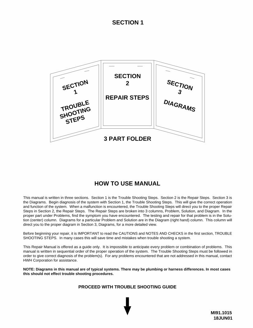
HOW TO USE MANUAL
PROCEED WITH TROUBLE SHOOTING GUIDE
This manual is written in three sections. Section 1 is the Trouble Shooting Steps. Section 2 is the Repair Steps. Section 3 isthe Diagrams. Begin diagnosis of the system with Section 1, the Trouble Shooting Steps. This will give the correct operationand function of the system. When a malfunction is encountered, the Trouble Shooting Steps will direct you to the proper RepairSteps in Section 2, the Repair Steps. The Repair Steps are broken into 3 columns, Problem, Solution, and Diagram. In theproper part under Problems, find the symptom you have encountered. The testing and repair for that problem is in the Solu-tion (center) column. Diagrams for a particular Problem and Solution are in the Diagram (right hand) column. This column willdirect you to the proper diagram in Section 3, Diagrams, for a more detailed view.
Before beginning your repair, it is IMPORTANT to read the CAUTIONS and NOTES AND CHECKS in the first section, TROUBLESHOOTING STEPS. In many cases this will save time and mistakes when trouble shooting a system.
This Repair Manual is offered as a guide only. It is impossible to anticipate every problem or combination of problems. Thismanual is written in sequential order of the proper operation of the system. The Trouble Shooting Steps must be followed inorder to give correct diagnosis of the problem(s). For any problems encountered that are not addressed in this manual, contactHWH Corporation for assistance.
NOTE: Diagrams in this manual are of typical systems. There may be plumbing or harness differences. In most casesthis should not effect trouble shooting procedures.
TROUBLE SHOOTING
MI91.102103FEB99
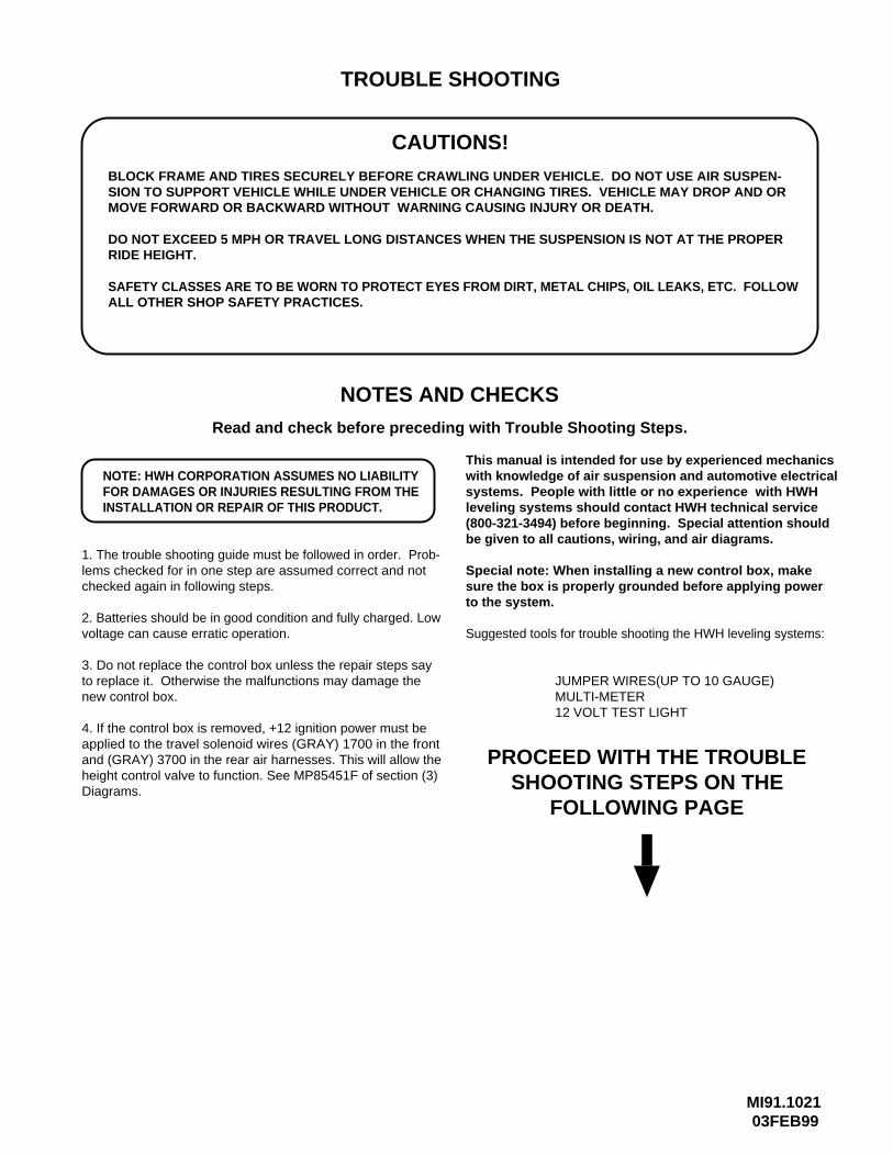
CAUTIONS!
BLOCK FRAME AND TIRES SECURELY BEFORE CRAWLING UNDER VEHICLE. DO NOT USE AIR SUSPEN-SION TO SUPPORT VEHICLE WHILE UNDER VEHICLE OR CHANGING TIRES. VEHICLE MAY DROP AND ORMOVE FORWARD OR BACKWARD WITHOUT WARNING CAUSING INJURY OR DEATH.
SAFETY CLASSES ARE TO BE WORN TO PROTECT EYES FROM DIRT, METAL CHIPS, OIL LEAKS, ETC. FOLLOWALL OTHER SHOP SAFETY PRACTICES.
NOTES AND CHECKS
Read and check before preceding with Trouble Shooting Steps.
NOTE: HWH CORPORATION ASSUMES NO LIABILITYFOR DAMAGES OR INJURIES RESULTING FROM THEINSTALLATION OR REPAIR OF THIS PRODUCT.
1. The trouble shooting guide must be followed in order. Prob-lems checked for in one step are assumed correct and notchecked again in following steps.
2. Batteries should be in good condition and fully charged. Lowvoltage can cause erratic operation.
3. Do not replace the control box unless the repair steps sayto replace it. Otherwise the malfunctions may damage thenew control box.
This manual is intended for use by experienced mechanicswith knowledge of air suspension and automotive electricalsystems. People with little or no experience with HWHleveling systems should contact HWH technical service(800-321-3494) before beginning. Special attention shouldbe given to all cautions, wiring, and air diagrams.
Special note: When installing a new control box, makesure the box is properly grounded before applying powerto the system.
Suggested tools for trouble shooting the HWH leveling systems:
JUMPER WIRES(UP TO 10 GAUGE)MULTI-METER12 VOLT TEST LIGHT
PROCEED WITH THE TROUBLESHOOTING STEPS ON THE
FOLLOWING PAGE
DO NOT EXCEED 5 MPH OR TRAVEL LONG DISTANCES WHEN THE SUSPENSION IS NOT AT THE PROPERRIDE HEIGHT.
4. If the control box is removed, +12 ignition power must be applied to the travel solenoid wires (GRAY) 1700 in the frontand (GRAY) 3700 in the rear air harnesses. This will allow theheight control valve to function. See MP85451F of section (3)Diagrams.
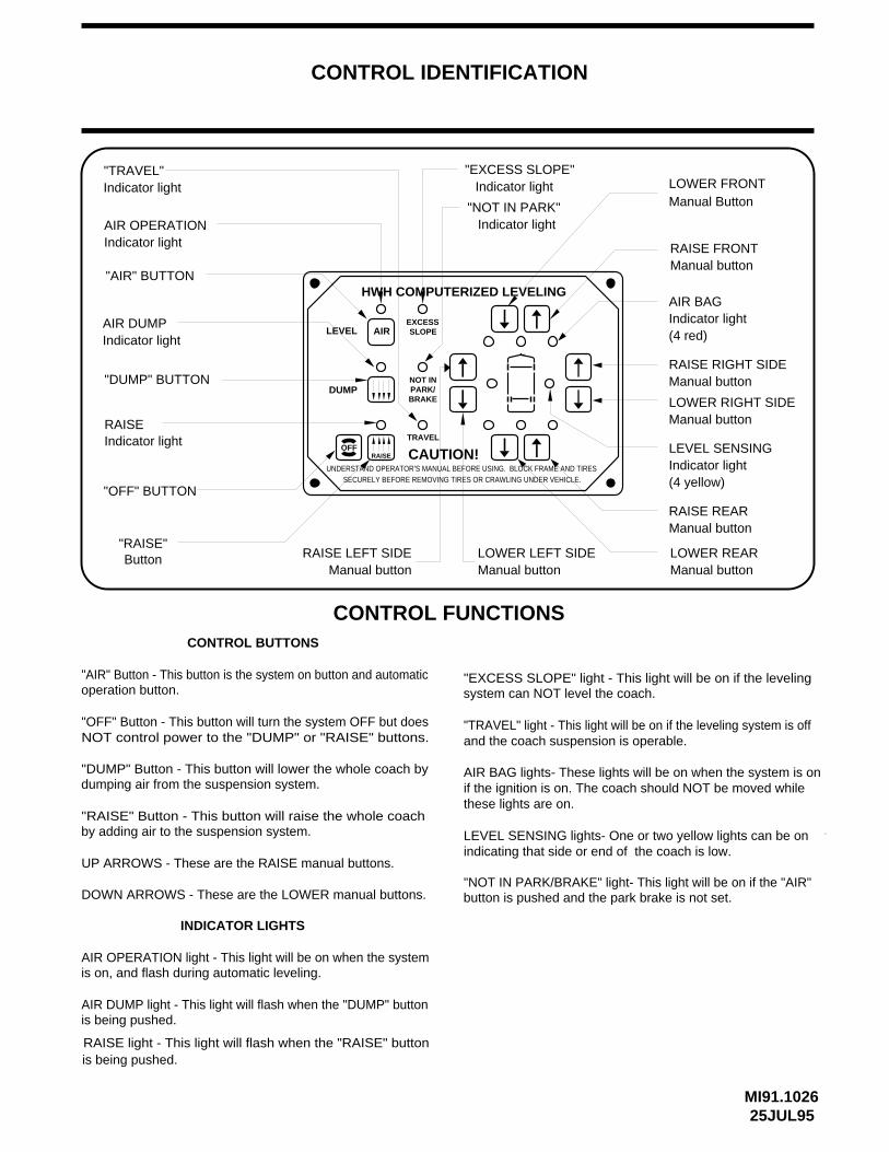
CONTROL IDENTIFICATION
"OFF" BUTTON
"EXCESS SLOPE"Indicator light
"NOT IN PARK"Indicator light
RAISE RIGHT SIDEManual button
LOWER RIGHT SIDEManual button
LEVEL SENSINGIndicator light (4 yellow)
Indicator light(4 red)
RAISE REARManual button
LOWER REARManual button
AIR OPERATIONIndicator light
AIR DUMPIndicator light
"RAISE"Button
"TRAVEL"Indicator light
AIR BAG
"AIR" Button - This button is the system on button and automaticoperation button.
"OFF" Button - This button will turn the system OFF but doesNOT control power to the "DUMP" or "RAISE" buttons.
"DUMP" Button - This button will lower the whole coach bydumping air from the suspension system.
"RAISE" Button - This button will raise the whole coach by adding air to the suspension system.
UP ARROWS - These are the RAISE manual buttons.
DOWN ARROWS - These are the LOWER manual buttons.
AIR OPERATION light - This light will be on when the systemis on, and flash during automatic leveling.
AIR DUMP light - This light will flash when the "DUMP" buttonis being pushed.
"EXCESS SLOPE" light - This light will be on if the levelingsystem can NOT level the coach.
"TRAVEL" light - This light will be on if the leveling system is offand the coach suspension is operable.
AIR BAG lights- These lights will be on when the system is on
CONTROL BUTTONS
INDICATOR LIGHTS
MI91.102625JUL95
CONTROL FUNCTIONS
"AIR" BUTTON
CAUTION!UNDERSTAND OPERATOR’S MANUAL BEFORE USING. BLOCK FRAME AND TIRES
SECURELY BEFORE REMOVING TIRES OR CRAWLING UNDER VEHICLE.
OFFRAISE
DUMP
TRAVEL
NOT INPARK/
HWH COMPUTERIZED LEVELING
LEVEL AIREXCESSSLOPE
BRAKE
"NOT IN PARK/BRAKE" light- This light will be on if the "AIR"
"DUMP" BUTTON
RAISEIndicator light
RAISE LEFT SIDEManual button
LOWER LEFT SIDEManual button
RAISE FRONTManual button
Manual ButtonLOWER FRONT
RAISE light - This light will flash when the "RAISE" buttonis being pushed.
button is pushed and the park brake is not set.
if the ignition is on. The coach should NOT be moved whilethese lights are on.
LEVEL SENSING lights- One or two yellow lights can be on indicating that side or end of the coach is low.
MI91.103116JUN00
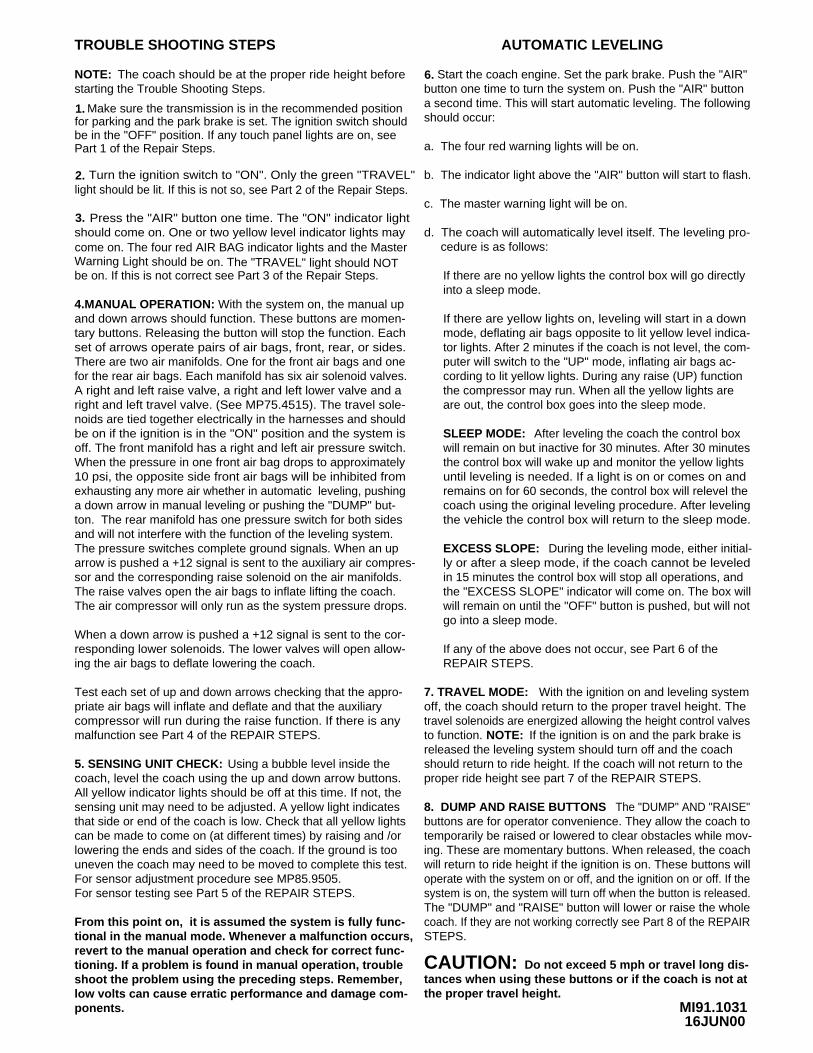
TROUBLE SHOOTING STEPS
Make sure the transmission is in the recommended positionfor parking and the park brake is set. The ignition switch shouldbe in the "OFF" position. If any touch panel lights are on, seePart 1 of the Repair Steps.
Turn the ignition switch to "ON". Only the green "TRAVEL"light should be lit. If this is not so, see Part 2 of the Repair Steps.
Press the "AIR" button one time. The "ON" indicator lightshould come on. One or two yellow level indicator lights maycome on. The four red AIR BAG indicator lights and the MasterWarning Light should be on. The "TRAVEL" light should NOTbe on. If this is not correct see Part 3 of the Repair Steps.
4.MANUAL OPERATION: With the system on, the manual up and down arrows should function. These buttons are momen-tary buttons. Releasing the button will stop the function. Eachset of arrows operate pairs of air bags, front, rear, or sides.There are two air manifolds. One for the front air bags and onefor the rear air bags. Each manifold has six air solenoid valves.A right and left raise valve, a right and left lower valve and a right and left travel valve. (See MP75.4515). The travel sole-noids are tied together electrically in the harnesses and shouldbe on if the ignition is in the "ON" position and the system isoff. The front manifold has a right and left air pressure switch.When the pressure in one front air bag drops to approximately10 psi, the opposite side front air bags will be inhibited fromexhausting any more air whether in automatic leveling, pushing
ton. The rear manifold has one pressure switch for both sidesand will not interfere with the function of the leveling system.The pressure switches complete ground signals. When an uparrow is pushed a +12 signal is sent to the auxiliary air compres-sor and the corresponding raise solenoid on the air manifolds.
NOTE: The coach should be at the proper ride height beforestarting the Trouble Shooting Steps.
The raise valves open the air bags to inflate lifting the coach.The air compressor will only run as the system pressure drops.
When a down arrow is pushed a +12 signal is sent to the cor-responding lower solenoids. The lower valves will open allow-ing the air bags to deflate lowering the coach.
Test each set of up and down arrows checking that the appro-priate air bags will inflate and deflate and that the auxiliary compressor will run during the raise function. If there is anymalfunction see Part 4 of the REPAIR STEPS.
5. SENSING UNIT CHECK:coach, level the coach using the up and down arrow buttons.All yellow indicator lights should be off at this time. If not, the sensing unit may need to be adjusted. A yellow light indicatesthat side or end of the coach is low. Check that all yellow lightscan be made to come on (at different times) by raising and /orlowering the ends and sides of the coach. If the ground is toouneven the coach may need to be moved to complete this test.
For sensor testing see Part 5 of the REPAIR STEPS.
From this point on, it is assumed the system is fully func-tional in the manual mode. Whenever a malfunction occurs,revert to the manual operation and check for correct func-tioning. If a problem is found in manual operation, troubleshoot the problem using the preceding steps. Remember,low volts can cause erratic performance and damage com-
AUTOMATIC LEVELING
Start the coach engine. Set the park brake. Push the "AIR"button one time to turn the system on. Push the "AIR" buttona second time. This will start automatic leveling. The followingshould occur:
a. The four red warning lights will be on.
b. The indicator light above the "AIR" button will start to flash.
c. The master warning light will be on.
d. The coach will automatically level itself. The leveling pro- cedure is as follows:
If there are no yellow lights the control box will go directlyinto a sleep mode.
If there are yellow lights on, leveling will start in a down mode, deflating air bags opposite to lit yellow level indica-tor lights. After 2 minutes if the coach is not level, the com-puter will switch to the "UP" mode, inflating air bags ac-
the compressor may run. When all the yellow lights areare out, the control box goes into the sleep mode.
SLEEP MODE:will remain on but inactive for 30 minutes. After 30 minutesthe control box will wake up and monitor the yellow lightsuntil leveling is needed. If a light is on or comes on and remains on for 60 seconds, the control box will relevel the coach using the original leveling procedure. After levelingthe vehicle the control box will return to the sleep mode.
EXCESS SLOPE:ly or after a sleep mode, if the coach cannot be leveledin 15 minutes the control box will stop all operations, andthe "EXCESS SLOPE" indicator will come on. The box willwill remain on until the "OFF" button is pushed, but will not
If any of the above does not occur, see Part 6 of the REPAIR STEPS.
travel solenoids are energized allowing the height control valves
7. TRAVEL MODE:
8. DUMP AND RAISE BUTTONS
temporarily be raised or lowered to clear obstacles while mov-ing. These are momentary buttons. When released, the coachwill return to ride height if the ignition is on. These buttons willoperate with the system on or off, and the ignition on or off. If thesystem is on, the system will turn off when the button is released.The "DUMP" and "RAISE" button will lower or raise the wholecoach. If they are not working correctly see Part 8 of the REPAIRSTEPS.
CAUTION: Do not exceed 5 mph or travel long dis-tances when using these buttons or if the coach is not atthe proper travel height.
Using a bubble level inside the
After leveling the coach the control box
During the leveling mode, either initial-
With the ignition on and leveling systemoff, the coach should return to the proper travel height. The
The "DUMP" AND "RAISE"buttons are for operator convenience. They allow the coach to
For sensor adjustment procedure see MP85.9505.
ponents.
go into a sleep mode.
cording to lit yellow lights. During any raise (UP) function
1.
2.
3.
6.
a down arrow in manual leveling or pushing the "DUMP" but-
to function. NOTE: If the ignition is on and the park brake isreleased the leveling system should turn off and the coach should return to ride height. If the coach will not return to the proper ride height see part 7 of the REPAIR STEPS.
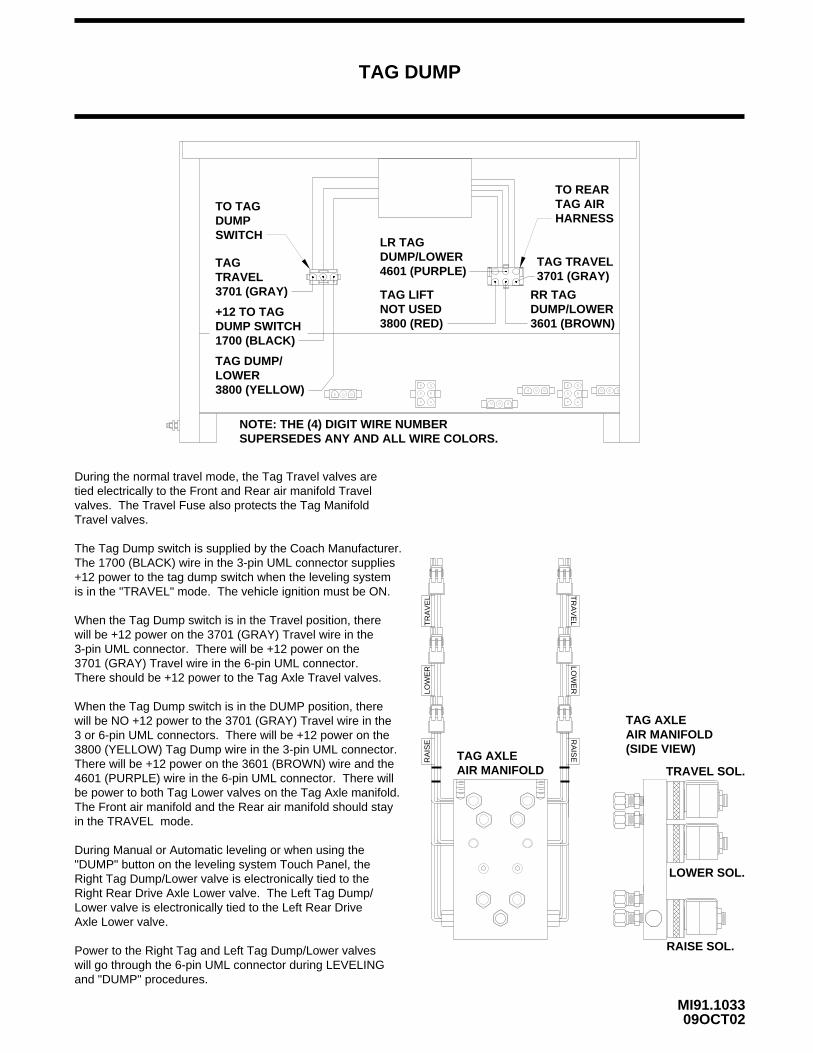
TAG DUMP
09OCT02MI91.1033
During the normal travel mode, the Tag Travel valves aretied electrically to the Front and Rear air manifold Travelvalves. The Travel Fuse also protects the Tag ManifoldTravel valves.
The Tag Dump switch is supplied by the Coach Manufacturer.The 1700 (BLACK) wire in the 3-pin UML connector supplies+12 power to the tag dump switch when the leveling systemis in the "TRAVEL" mode. The vehicle ignition must be ON.
When the Tag Dump switch is in the Travel position, therewill be +12 power on the 3701 (GRAY) Travel wire in the 3-pin UML connector. There will be +12 power on the3701 (GRAY) Travel wire in the 6-pin UML connector.There should be +12 power to the Tag Axle Travel valves.
When the Tag Dump switch is in the DUMP position, therewill be NO +12 power to the 3701 (GRAY) Travel wire in the3 or 6-pin UML connectors. There will be +12 power on the3800 (YELLOW) Tag Dump wire in the 3-pin UML connector.There will be +12 power on the 3601 (BROWN) wire and the4601 (PURPLE) wire in the 6-pin UML connector. There willbe power to both Tag Lower valves on the Tag Axle manifold.The Front air manifold and the Rear air manifold should stayin the TRAVEL mode.
During Manual or Automatic leveling or when using the"DUMP" button on the leveling system Touch Panel, theRight Tag Dump/Lower valve is electronically tied to theRight Rear Drive Axle Lower valve. The Left Tag Dump/Lower valve is electronically tied to the Left Rear DriveAxle Lower valve.
Power to the Right Tag and Left Tag Dump/Lower valveswill go through the 6-pin UML connector during LEVELINGand "DUMP" procedures.
TO REARTAG AIRHARNESS
TO TAGDUMPSWITCH
TAGTRAVEL3701 (GRAY)
1700 (BLACK)
+12 TO TAGDUMP SWITCH
3800 (YELLOW)LOWERTAG DUMP/
LR TAGDUMP/LOWER4601 (PURPLE)
TAG LIFTNOT USED3800 (RED) 3601 (BROWN)
DUMP/LOWERRR TAG
3701 (GRAY)TAG TRAVEL
NOTE: THE (4) DIGIT WIRE NUMBER SUPERSEDES ANY AND ALL WIRE COLORS.
LOW
ER
RA
ISE
TR
AV
EL
TRAVEL SOL.
LOWER SOL.
RAISE SOL.
TAG AXLEAIR MANIFOLD
TAG AXLEAIR MANIFOLD(SIDE VIEW)
LOW
ER
RA
ISE
TR
AV
EL
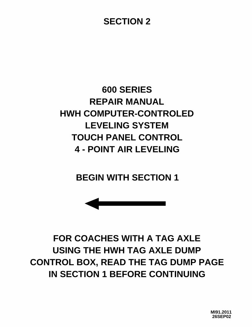
SECTION 2
600 SERIESREPAIR MANUAL
HWH COMPUTER-CONTROLED
TOUCH PANEL CONTROL4 - POINT AIR LEVELING
BEGIN WITH SECTION 1
LEVELING SYSTEM
MI91.201126SEP02
IN SECTION 1 BEFORE CONTINUINGCONTROL BOX, READ THE TAG DUMP PAGE
USING THE HWH TAG AXLE DUMPFOR COACHES WITH A TAG AXLE
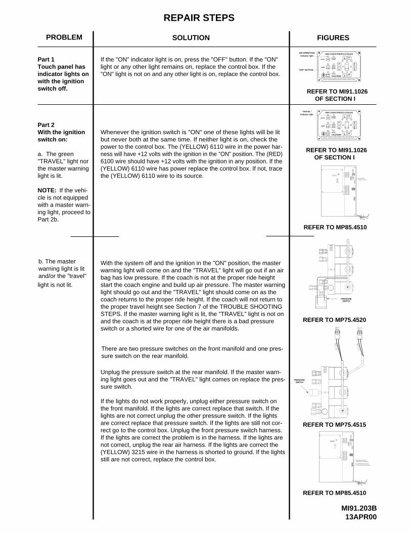
(YELLOW) 6110 wire has power replace the control box. If not, trace6100 wire should have +12 volts with the ignition in any position. If theness will have +12 volts with the ignition in the "ON" position. The (RED)power to the control box. The (YELLOW) 6110 wire in the power har-
There are two pressure switches on the front manifold and one pres-
but never both at the same time. If neither light is on, check theWhenever the ignition switch is "ON" one of these lights will be lit
"ON" light is not on and any other light is on, replace the control box.light or any other light remains on, replace the control box. If the If the "ON" indicator light is on, press the "OFF" button. If the "ON"
SOLUTION
REPAIR STEPS
warning light is litand/or the "travel"
sure switch on the rear manifold.
the master warning"TRAVEL" light nor
indicator lights on
b. The master
light is lit.
a. The green
switch on:With the ignition Part 2
switch off.with the ignition
Touch panel has
PROBLEM
Part 1
the (YELLOW) 6110 wire to its source.
REFER TO MP85.4510
REFER TO MP75.4515
REFER TO MP75.4520
PRESSURESWITCH
13APR00MI91.203B
FROM FRONT AIR HARNESSPRESSURE SW INPUTS
RF AIR PRESSURE SW-ORANGE
LF AIR PRESSURE SW-BLACK
7
8
910
11
56
1
2
3
4
PO
WE
RH
AR
NE
SS
5
5
5
5
7.5
5
5
15
5
5
15
SWITCHPRESSURE
REFER TO MP85.4510
AIR
HWH COMPUTERIZED LEVELING
RAISE
UNDERSTAND OPERATOR’S MANUAL BEFORE USING. BLOCK FRAME AND TIRESSECURELY BEFORE REMOVING TIRES OR CRAWLING UNDER VEHICLE.
REFER TO MI91.1026 OF SECTION I
OF SECTION IREFER TO MI91.1026
AIR
HWH COMPUTERIZED LEVELING
RAISE
SECURELY BEFORE REMOVING TIRES OR CRAWLING UNDER VEHICLE.UNDERSTAND OPERATOR’S MANUAL BEFORE USING. BLOCK FRAME AND TIRES
FIGURES
indicator light"TRAVEL"
DUMP
OFF
LEVEL
"OFF" BUTTONDUMP
OFF
indicator lightAIR OPERATION
LEVEL
11 7.5
109
8
7
65 5
5
5
5
5
5
IGNITION-YELLOW
BATTERY-RED
3 15
154
PO
WE
R
2
1 5
5
HA
RN
ES
S
PARK/
TRAVEL
CAUTION!
BRAKE
EXCESSSLOPE
NOT IN
NOT IN
TRAVEL
CAUTION!
BRAKEPARK/
EXCESSSLOPE
NOTE: If the vehi-cle is not equippedwith a master warn-ing light, proceed toPart 2b.
light is not lit.
With the system off and the ignition in the "ON" position, the masterwarning light will come on and the "TRAVEL" light will go out if an air bag has low pressure. If the coach is not at the proper ride height start the coach engine and build up air pressure. The master warninglight should go out and the "TRAVEL" light should come on as the coach returns to the proper ride height. If the coach will not return tothe proper travel height see Section 7 of the TROUBLE SHOOTINGSTEPS. If the master warning light is lit, the "TRAVEL" light is not onand the coach is at the proper ride height there is a bad pressureswitch or a shorted wire for one of the air manifolds.
Unplug the pressure switch at the rear manifold. If the master warn-ing light goes out and the "TRAVEL" light comes on replace the pres-sure switch.
If the lights do not work properly, unplug either pressure switch on the front manifold. If the lights are correct replace that switch. If thelights are not correct unplug the other pressure switch. If the lightsare correct replace that pressure switch. If the lights are still not cor-rect go to the control box. Unplug the front pressure switch harness.If the lights are correct the problem is in the harness. If the lights arenot correct, unplug the rear air harness. If the lights are correct the(YELLOW) 3215 wire in the harness is shorted to ground. If the lightsstill are not correct, replace the control box.
REPAIR STEPS
SOLUTION DIAGRAMSPROBLEM
MI91.203D13APR00
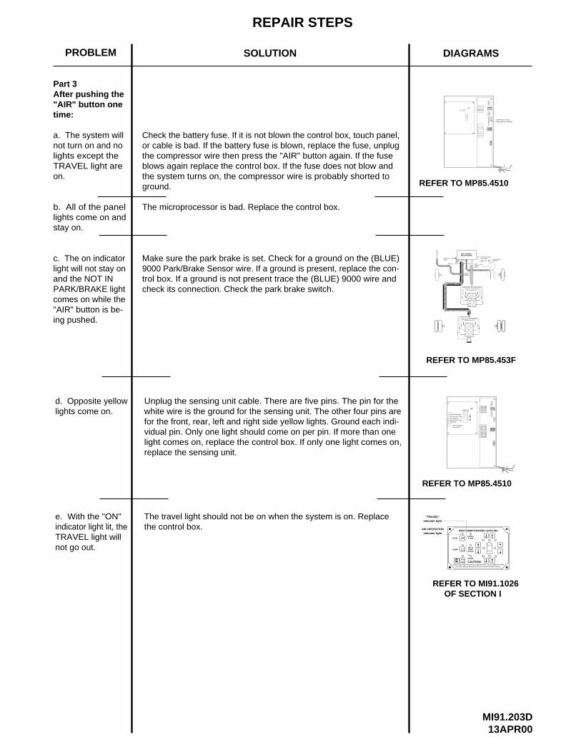
Part 3After pushing the"AIR" button onetime:
b. All of the panellights come on and stay on.
The microprocessor is bad. Replace the control box.
a. The system willnot turn on and nolights except theTRAVEL light are on.
c. The on indicatorlight will not stay onand the NOT IN PARK/BRAKE lightcomes on while the"AIR" button is be-ing pushed.
d. Opposite yellowlights come on.
Check the battery fuse. If it is not blown the control box, touch panel,or cable is bad. If the battery fuse is blown, replace the fuse, unplugthe compressor wire then press the "AIR" button again. If the fuse blows again replace the control box. If the fuse does not blow and the system turns on, the compressor wire is probably shorted to ground.
Unplug the sensing unit cable. There are five pins. The pin for the white wire is the ground for the sensing unit. The other four pins arefor the front, rear, left and right side yellow lights. Ground each indi-vidual pin. Only one light should come on per pin. If more than onelight comes on, replace the control box. If only one light comes on,replace the sensing unit.
e. With the "ON" indicator light lit, theTRAVEL light will not go out.
The travel light should not be on when the system is on. Replace the control box.
REFER TO MP85.4510
COMPRESSOR - BLACK
FROM REAR AIR HARNESS
REFER TO MP85.4510
11 7.5
109
8
7
65 5
5
5
5
5
5
2 5
154
3 15
1 5
YELLOW-LEFT SIDE
WHITE-(GROUND)
CO
MP
RE
SS
OR
3 15
SEE CONTROLBOX DIAGRAM
TO BRAKE LIGHTON DASH
PARK BRAKE SWITCH
GROUNDSTUD
WHITE
POWERHARNESS
PARKBRAKEBLUE
REFER TO MP85.453F
BLACK-FRONT
GREEN-RIGHT SIDERED-REAR
LEVEL SENSINGUNIT INPUTS
AIR OPERATION
REFER TO MI91.1026
indicator light
NOT IN
UNDERSTAND OPERATOR’S MANUAL BEFORE USING. BLOCK FRAME AND TIRESSECURELY BEFORE REMOVING TIRES OR CRAWLING UNDER VEHICLE.
OF SECTION I
RAISE
DUMP
OFFCAUTION!
PARK/BRAKE
TRAVEL
HWH COMPUTERIZED LEVELING
AIRLEVELEXCESSSLOPE
"TRAVEL"indicator light
Make sure the park brake is set. Check for a ground on the (BLUE)9000 Park/Brake Sensor wire. If a ground is present, replace the con-trol box. If a ground is not present trace the (BLUE) 9000 wire and check its connection. Check the park brake switch.
REPAIR STEPS
SOLUTION DIAGRAMSPROBLEM
MI91.203F13APR00
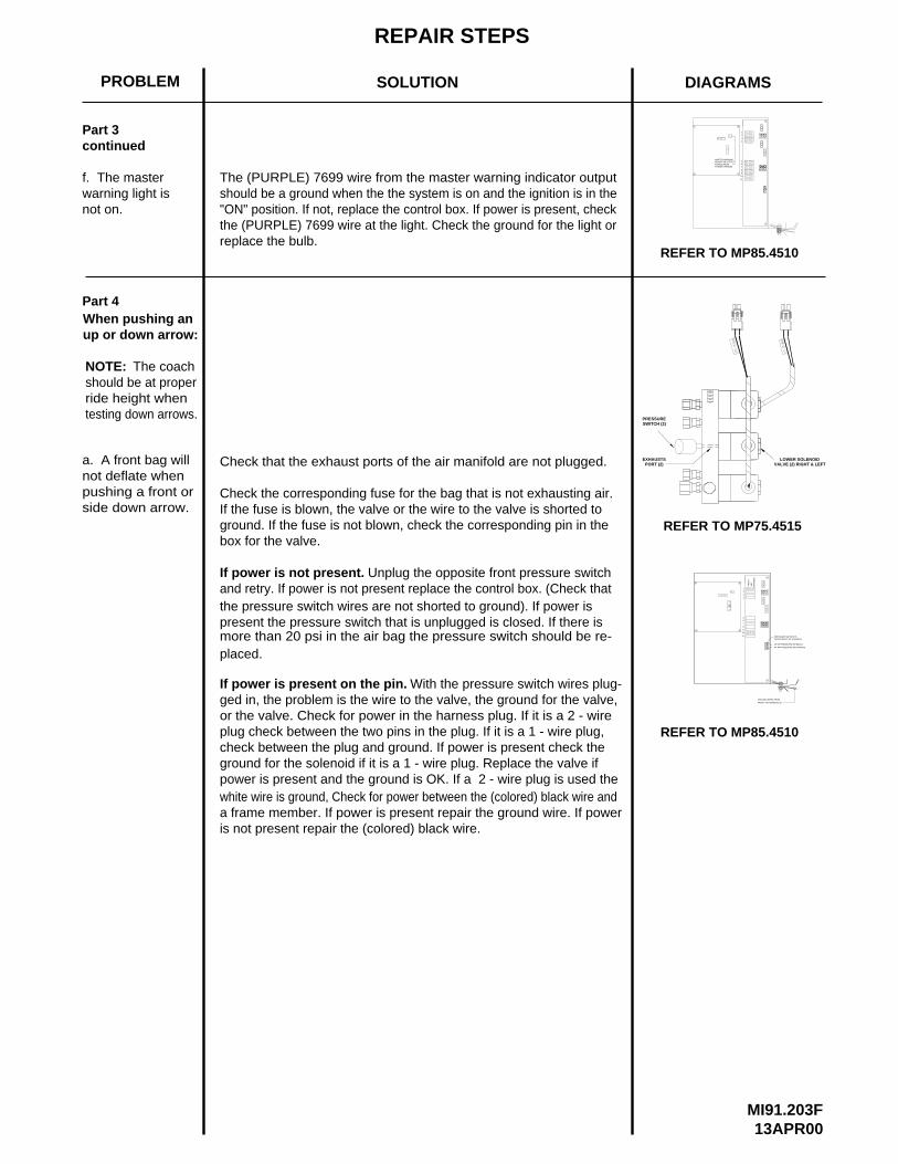
Part 3continued
f. The masterwarning light is
Part 4When pushing anup or down arrow:
NOTE: The coachshould be at properride height when testing down arrows.
a. A front bag will not deflate when pushing a front orside down arrow.
Check that the exhaust ports of the air manifold are not plugged.
Check the corresponding fuse for the bag that is not exhausting air.If the fuse is blown, the valve or the wire to the valve is shorted toground. If the fuse is not blown, check the corresponding pin in the
If power is not present.and retry. If power is not present replace the control box. (Check that
more than 20 psi in the air bag the pressure switch should be re-
If power is present on the pin.ged in, the problem is the wire to the valve, the ground for the valve,or the valve. Check for power in the harness plug. If it is a 2 - wireplug check between the two pins in the plug. If it is a 1 - wire plug,check between the plug and ground. If power is present check theground for the solenoid if it is a 1 - wire plug. Replace the valve ifpower is present and the ground is OK. If a 2 - wire plug is used the
not on.
box for the valve.
Unplug the opposite front pressure switch
With the pressure switch wires plug-
REFER TO MP85.4510
7.5
56
7
8
910
11
5
5
5
5
5
5
15
153
4
1
2 5
5
MASTER WARNINGINDICATOR OUTPUTPURPLE FROMPOWER HARNESS
REFER TO MP75.4515
SWITCH (2)PRESSURE
RF AIR PRESSURE SW-ORANGE
REFER TO MP85.4510
LF AIR PRESSURE SW-BLACK
HA
RN
ES
SA
IR
11
109
8
7
5
65
4
3
2
1 5
PRESSURE SW INPUTSFROM FRONT AIR HARNESS
EXHAUSTSPORT (2)
LOWER SOLENOIDVALVE (2) RIGHT & LEFT
FR
ON
T
GROUND WIRES FROM
FRONT AIR HARNESS (2)
the pressure switch wires are not shorted to ground). If power ispresent the pressure switch that is unplugged is closed. If there is
placed.
The (PURPLE) 7699 wire from the master warning indicator outputshould be a ground when the the system is on and the ignition is in the"ON" position. If not, replace the control box. If power is present, checkthe (PURPLE) 7699 wire at the light. Check the ground for the light orreplace the bulb.
white wire is ground, Check for power between the (colored) black wire anda frame member. If power is present repair the ground wire. If poweris not present repair the (colored) black wire.
REPAIR STEPS
SOLUTION DIAGRAMSPROBLEM
MI91.203H13APR00
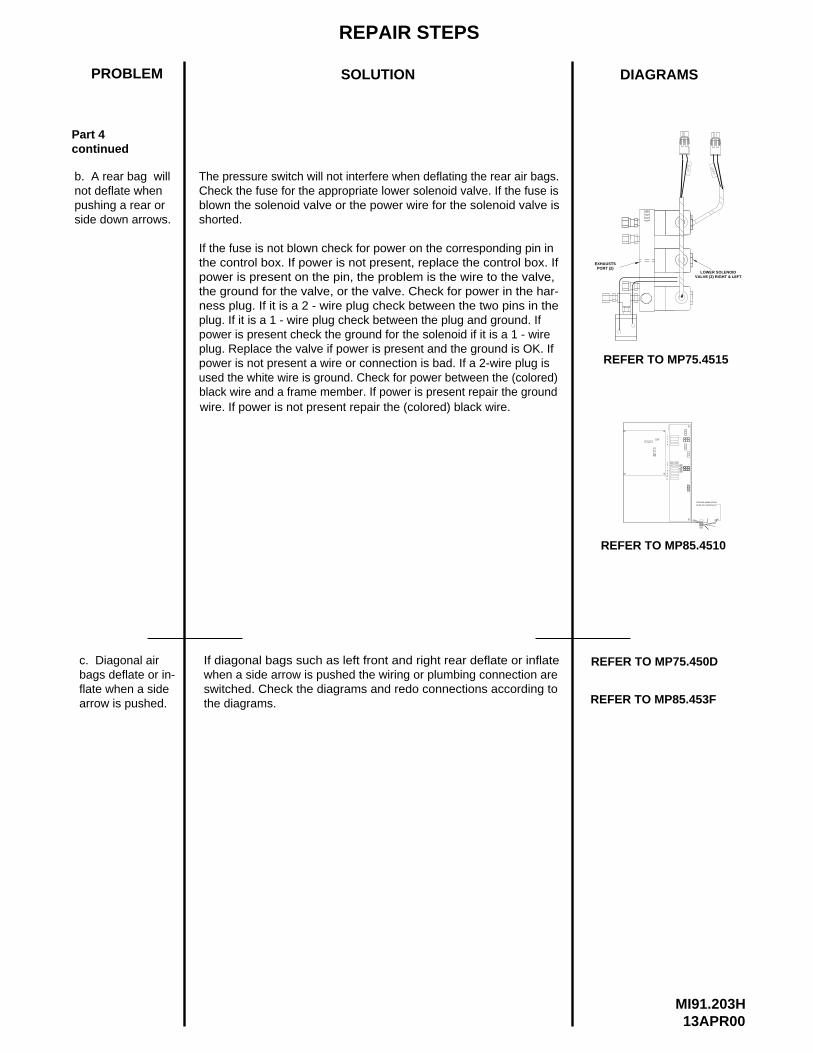
Part 4continued
b. A rear bag willnot deflate whenpushing a rear or side down arrows.
The pressure switch will not interfere when deflating the rear air bags.Check the fuse for the appropriate lower solenoid valve. If the fuse isblown the solenoid valve or the power wire for the solenoid valve is shorted.
If the fuse is not blown check for power on the corresponding pin inthe control box. If power is not present, replace the control box. Ifpower is present on the pin, the problem is the wire to the valve, the ground for the valve, or the valve. Check for power in the har-ness plug. If it is a 2 - wire plug check between the two pins in theplug. If it is a 1 - wire plug check between the plug and ground. Ifpower is present check the ground for the solenoid if it is a 1 - wireplug. Replace the valve if power is present and the ground is OK. Ifpower is not present a wire or connection is bad. If a 2-wire plug is
c. Diagonal airbags deflate or in-flate when a sidearrow is pushed.
If diagonal bags such as left front and right rear deflate or inflate when a side arrow is pushed the wiring or plumbing connection areswitched. Check the diagrams and redo connections according to the diagrams.
PORT (2)EXHAUSTS
REFER TO MP75.4515
LOWER SOLENOIDVALVE (2) RIGHT & LEFT
REFER TO MP85.4510
HA
RN
ES
SR
EA
R A
IR
11
109
8
7
65
5
5
4
3
2
1
GROUND WIRES FROM
REAR AIR HARNESS (2)
REFER TO MP75.450D
REFER TO MP85.453F
used the white wire is ground. Check for power between the (colored)black wire and a frame member. If power is present repair the groundwire. If power is not present repair the (colored) black wire.
REPAIR STEPS
SOLUTION DIAGRAMSPROBLEM
MI91.203J13APR00
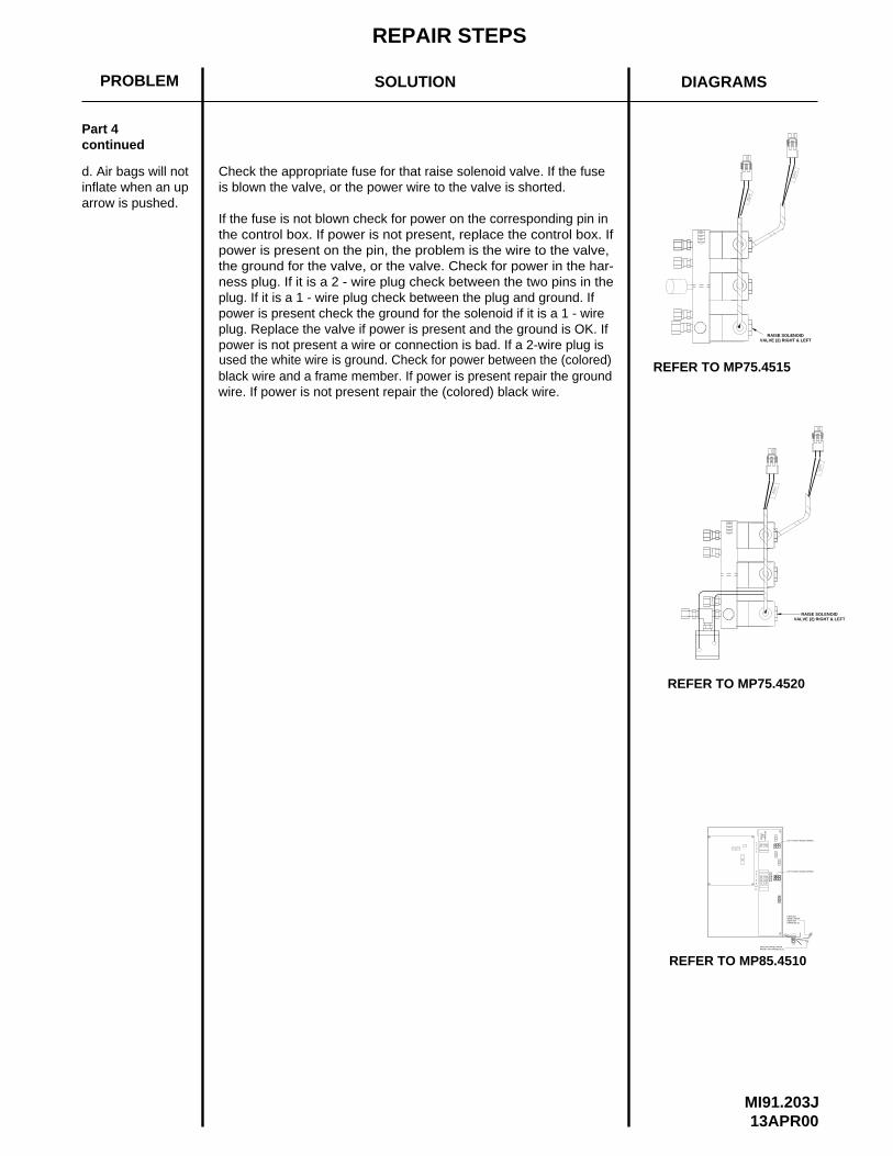
Check the appropriate fuse for that raise solenoid valve. If the fuseis blown the valve, or the power wire to the valve is shorted.
power is not present a wire or connection is bad. If a 2-wire plug isplug. Replace the valve if power is present and the ground is OK. Ifpower is present check the ground for the solenoid if it is a 1 - wireplug. If it is a 1 - wire plug check between the plug and ground. Ifness plug. If it is a 2 - wire plug check between the two pins in thethe ground for the valve, or the valve. Check for power in the har-power is present on the pin, the problem is the wire to the valve, the control box. If power is not present, replace the control box. IfIf the fuse is not blown check for power on the corresponding pin in
d. Air bags will notinflate when an uparrow is pushed.
REFER TO MP75.4520
RAISE SOLENOIDVALVE (2) RIGHT & LEFT
REFER TO MP75.4515
RAISE SOLENOIDVALVE (2) RIGHT & LEFT
REFER TO MP85.4510
10
11
HA
RN
ES
S
FR
ON
T
4
LEFT FRONT RAISE-GREEN
59
5
5
56
7
8
5
1
2
3
AIR
RE
AR
AIR
HA
RN
ES
S
GROUNDWIRES FROMREAR AIRHARNESS (2)
GROUND WIRES FROMFRONT AIR HARNESS (2)
LEFT FRONT RAISE-GREEN
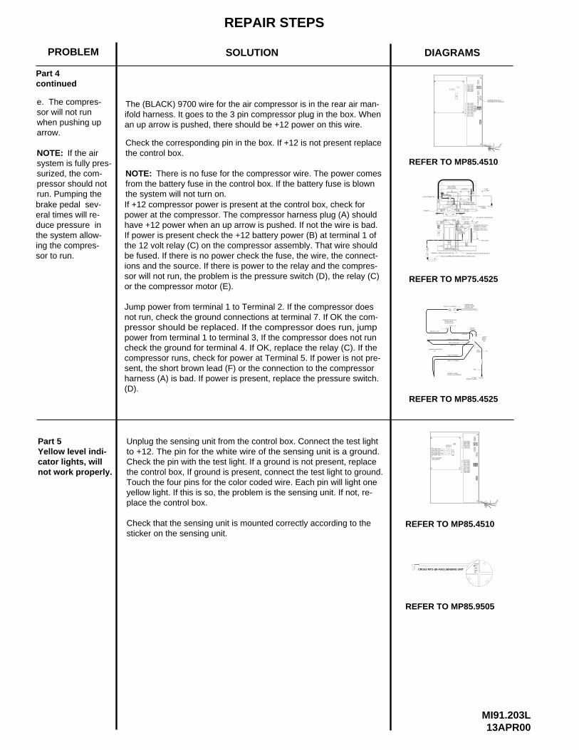
Part 4continued
used the white wire is ground. Check for power between the (colored)black wire and a frame member. If power is present repair the groundwire. If power is not present repair the (colored) black wire.
MI91.203L13APR00
arrow.
NOTE:
surized, the com-system is fully pres-
when pushing upsor will not run e. The compres-
run. Pumping thepressor should not
sor to run.ing the compres-the system allow-duce pressure ineral times will re-brake pedal sev-
not work properly.cator lights, will Yellow level indi-Part 5
the system will not turn on.
power at the compressor. The compressor harness plug (A) should
Check that the sensing unit is mounted correctly according to the
yellow light. If this is so, the problem is the sensing unit. If not, re-Touch the four pins for the color coded wire. Each pin will light onethe control box, If ground is present, connect the test light to ground.Check the pin with the test light. If a ground is not present, replaceto +12. The pin for the white wire of the sensing unit is a ground.Unplug the sensing unit from the control box. Connect the test light
harness (A) is bad. If power is present, replace the pressure switch.sent, the short brown lead (F) or the connection to the compressorcompressor runs, check for power at Terminal 5. If power is not pre-check the ground for terminal 4. If OK, replace the relay (C). If thepower from terminal 1 to terminal 3, If the compressor does not runpressor should be replaced. If the compressor does run, jumpnot run, check the ground connections at terminal 7. If OK the com-Jump power from terminal 1 to Terminal 2. If the compressor does
or the compressor motor (E).sor will not run, the problem is the pressure switch (D), the relay (C)ions and the source. If there is power to the relay and the compres-be fused. If there is no power check the fuse, the wire, the connect-the 12 volt relay (C) on the compressor assembly. That wire shouldIf power is present check the +12 battery power (B) at terminal 1 ofhave +12 power when an up arrow is pushed. If not the wire is bad.
If +12 compressor power is present at the control box, check for
place the control box.
sticker on the sensing unit.
(D).
Check the corresponding pin in the box. If +12 is not present replace
There is no fuse for the compressor wire. The power comesfrom the battery fuse in the control box. If the battery fuse is blownNOTE:
the control box.If the air
REPAIR STEPS
SOLUTION DIAGRAMSPROBLEM
COMPRESSOR-BLACKFROM REAR AIR HARNESS
REFER TO MP85.4510
56
7
8
910
11
5
5
5
5
5
5
7.5
2
4
3
1
CO
MP
RE
SS
OR
5
15
15
5
REFER TO MP85.9505
11
109
8
7
65
1
3
4
2
7.5
5
5
5
5
5
5
5
15
15
5
BLACK-COMPRESSOR HARNESS FROM CONTROL BOX
NORMALLY OPEN AIR SOLENOID (3)
12 VOLT RELAY (2)
AIR FILTER
(OPEN AT 115 P.S.I.)(CLOSED AT 105 P.S.I.)
NORMALLY CLOSEDPRESSURE SWITCH (1)
AIR LINE TO SUSPENSION
POWERTO +12 BATT
CHECK VALVE (4)
GRAY FROM AIR SOLENOID
+12 SIGNAL FROMPRESSURE SWITCH
GROUND
FUSE15 AMP
FLOW
GROUND TO RELAY MOUNTING BOLT
REFER TO MP75.4525
REFER TO MP85.4525
HA
RN
ES
SR
EA
R A
IR
BATTERY-REDIGNITION-YELLOWBATTERY-REDIGNITION-YELLOWBATTERY-RED
LEVEL SENSINGUNIT INPUTS
CROSS MTG (BI-AXIS) SENSING UNIT
REAR
THIS
SIDEUP
REFER TO MP85.4510
Part 4continued
BLACK ( GROUND )
RED +12
GROUNDWHITE
GRAY (GROUND)
GRAY (+12 SIGNAL)
+12 VOLTBATTERY POWER
NORMALLY OPEN12 VOLT AIR SOLENOID
12 VOLTESSEX RELAY
BROWN +12 (F)
ORANGE
PRESSURE SWITCH (D)OPEN 115 PSICLOSE 105 PSI
COMPRESSORHARNESS FROMCONTROL BOX
BLACK (+12 SIGNAL)
COMPRESSOR MOTOR
RED
FUSE15 AMP
(A)
(E)
6
5
RELAY MTG. BOLT
7
4
1
2
(C)
(B)
3
The (BLACK) 9700 wire for the air compressor is in the rear air man-ifold harness. It goes to the 3 pin compressor plug in the box. Whenan up arrow is pushed, there should be +12 power on this wire.
REPAIR STEPS
SOLUTION DIAGRAMSPROBLEM
MI91.203N16JUN00
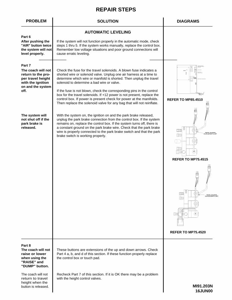
Part 7The coach will notreturn to the pro-per travel heightwith the ignitionon and the systemoff.
Check the fuse for the travel solenoids. A blown fuse indicates ashorted wire or solenoid valve. Unplug one air harness at a time to determine which wire or manifold is shorted. Then unplug the travelsolenoid to determine a bad wire or valve.
If the fuse is not blown, check the corresponding pins in the controlbox for the travel solenoids. If +12 power is not present, replace the control box. If power is present check for power at the manifolds.Then replace the solenoid valve for any bag that will not reinflate.
These buttons are extensions of the up and down arrows. CheckPart 4 a, b, and d of this section. If these function properly replace the control box or touch pad.
Recheck Part 7 of this section. If it is OK there may be a problemwith the height control valves.
Part 8The coach will notraise or lower when using the "RAISE" and "DUMP" button.
The coach will not return to travelheight when the button is released.
Part 6
level properly.the system will not"AIR" button twiceAfter pushing the
AUTOMATIC LEVELING
Remember low voltage situations and poor ground connections willsteps 1 thru 5. If the system works manually, replace the control box.If the system will not function properly in the automatic mode, check
cause erratic leveling.
REFER TO MP85.4510
56
7
8
910
11 7.5
BATTERY-RED
IGNITION-YELLOW
4
3
1
2
HA
RN
ES
SP
OW
ER
REFER TO MP75.4515
VALVE (2) RIGHT & LEFTTRAVEL SOLENOID
REFER TO MP75.4520
TRAVEL SOLENOIDVALVE (2) RIGHT & LEFT
FR
ON
TA
IRH
AR
NE
SS
BATTERY-RED
REAR TRAVEL SOLENOID-GRAY
park brake isnot shut off if theThe system will
released.
With the system on, the ignition on and the park brake released,unplug the park brake connection from the control box. If the systemremains on, replace the control box. If the system turns off, there isa constant ground on the park brake wire. Check that the park brakewire is properly connected to the park brake switch and that the parkbrake switch is working properly.
PARK BRAKE SENSORFROM POWER HARNESS -(BLUE) 9000
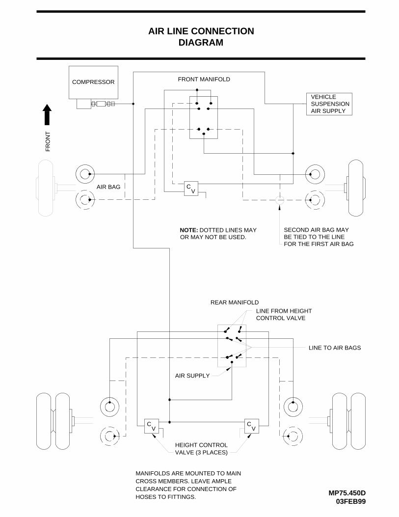
DIAGRAM
MP75.450D03FEB99
FR
ON
T
CV
HEIGHT CONTROLVALVE (3 PLACES)
MANIFOLDS ARE MOUNTED TO MAINCROSS MEMBERS. LEAVE AMPLECLEARANCE FOR CONNECTION OFHOSES TO FITTINGS.
VC
COMPRESSOR FRONT MANIFOLD
AIR BAG
CV
AIR LINE CONNECTION
REAR MANIFOLD
LINE FROM HEIGHTCONTROL VALVE
AIR SUPPLY
LINE TO AIR BAGS
NOTE: DOTTED LINES MAYOR MAY NOT BE USED.
SECOND AIR BAG MAYBE TIED TO THE LINEFOR THE FIRST AIR BAG
VEHICLESUSPENSIONAIR SUPPLY
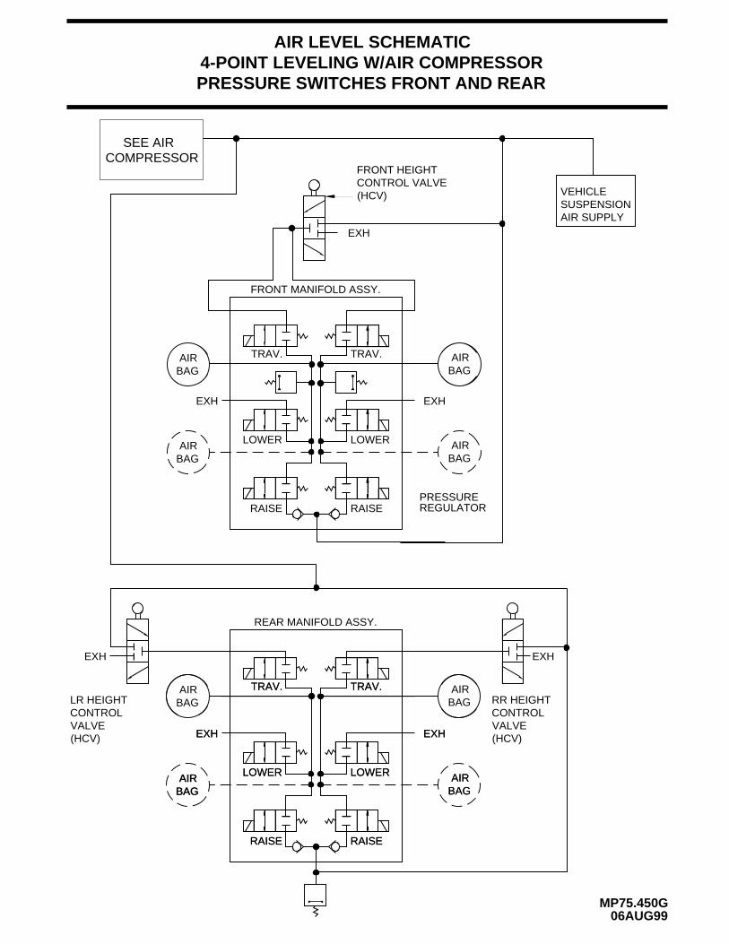
EXH EXH
AIRBAG
AIRBAG
REAR MANIFOLD ASSY.
EXHEXH
TRAV.
LOWER
RAISE
TRAV.
LOWER
RAISE
4-POINT LEVELING W/AIR COMPRESSORPRESSURE SWITCHES FRONT AND REAR
MP75.450G06AUG99
RAISE
LOWER
TRAV.
RAISE
LOWER
TRAV.
EXH EXH
BAGAIR
BAGAIR
AIRBAG BAG
AIR
AIR LEVEL SCHEMATIC
COMPRESSORSEE AIR
RAISE RAISE
FRONT MANIFOLD ASSY.
EXH
BAGAIR LOWER
BAGAIR TRAV.
LOWER
TRAV.
EXH
BAGAIR
AIRBAG
(HCV)CONTROL VALVEFRONT HEIGHT
EXH
PRESSUREREGULATOR
LR HEIGHTCONTROLVALVE
RR HEIGHTCONTROLVALVE(HCV)(HCV)
VEHICLE SUSPENSIONAIR SUPPLY
RAISE
TRA
VE
L
LOW
ER
LOW
ER
TR
AV
EL RA
ISE
PRESS SW
PR
ES
S S
W
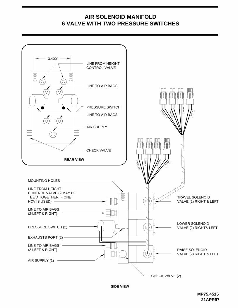
TRAVEL SOLENOID VALVE (2) RIGHT & LEFT
LOWER SOLENOIDVALVE (2) RIGHT& LEFT
RAISE SOLENOIDVALVE (2) RIGHT & LEFT
MOUNTING HOLES
LINE FROM HEIGHTCONTROL VALVE (2 MAY BETEE’D TOGETHER IF ONEHCV IS USED)
PRESSURE SWITCH (2)
EXHAUSTS PORT (2)
LINE TO AIR BAGS(2-LEFT & RIGHT)
AIR SUPPLY (1)
CHECK VALVE (2)
MP75.451521APR97
AIR SOLENOID MANIFOLD6 VALVE WITH TWO PRESSURE SWITCHES
CONTROL VALVELINE FROM HEIGHT
PRESSURE SWITCH
CHECK VALVE
AIR SUPPLY
LINE TO AIR BAGS
REAR VIEW
SIDE VIEW
LINE TO AIR BAGS
LINE TO AIR BAGS(2-LEFT & RIGHT)
3.400"
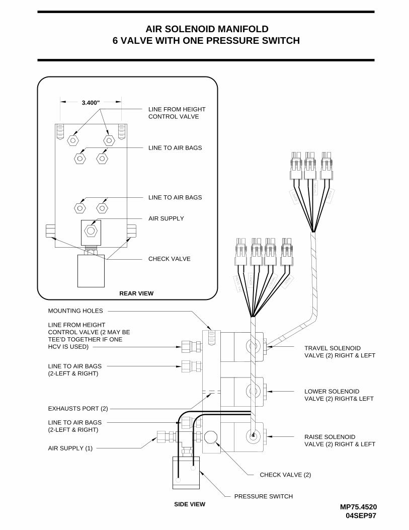
TRAVEL SOLENOID VALVE (2) RIGHT & LEFT
LOWER SOLENOIDVALVE (2) RIGHT& LEFT
RAISE SOLENOIDVALVE (2) RIGHT & LEFT
MOUNTING HOLES
LINE FROM HEIGHTCONTROL VALVE (2 MAY BETEE’D TOGETHER IF ONEHCV IS USED)
EXHAUSTS PORT (2)
LINE TO AIR BAGS(2-LEFT & RIGHT)
AIR SUPPLY (1)
CHECK VALVE (2)
MP75.452004SEP97
AIR SOLENOID MANIFOLD6 VALVE WITH ONE PRESSURE SWITCH
CONTROL VALVELINE FROM HEIGHT
CHECK VALVE
AIR SUPPLY
LINE TO AIR BAGS
REAR VIEW
SIDE VIEW
LINE TO AIR BAGS
LINE TO AIR BAGS(2-LEFT & RIGHT)
PRESSURE SWITCH
3.400"
COMPRESSOR HARNESS FROM CONTROL BOX - (BLACK) 9700
NORMALLY OPEN AIR SOLENOID (3)
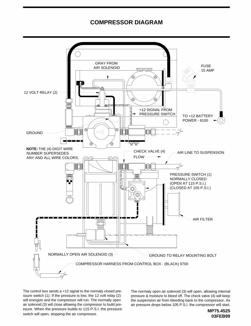
COMPRESSOR DIAGRAM
12 VOLT RELAY (2)
AIR FILTER
(OPEN AT 115 P.S.I.)(CLOSED AT 105 P.S.I.)
NORMALLY CLOSEDPRESSURE SWITCH (1)
03FEB99MP75.4525
AIR LINE TO SUSPENSIONCHECK VALVE (4)
GRAY FROM AIR SOLENOID
+12 SIGNAL FROMPRESSURE SWITCH
GROUND
FUSE15 AMP
FLOW
GROUND TO RELAY MOUNTING BOLT
TO +12 BATTERYPOWER - 6100
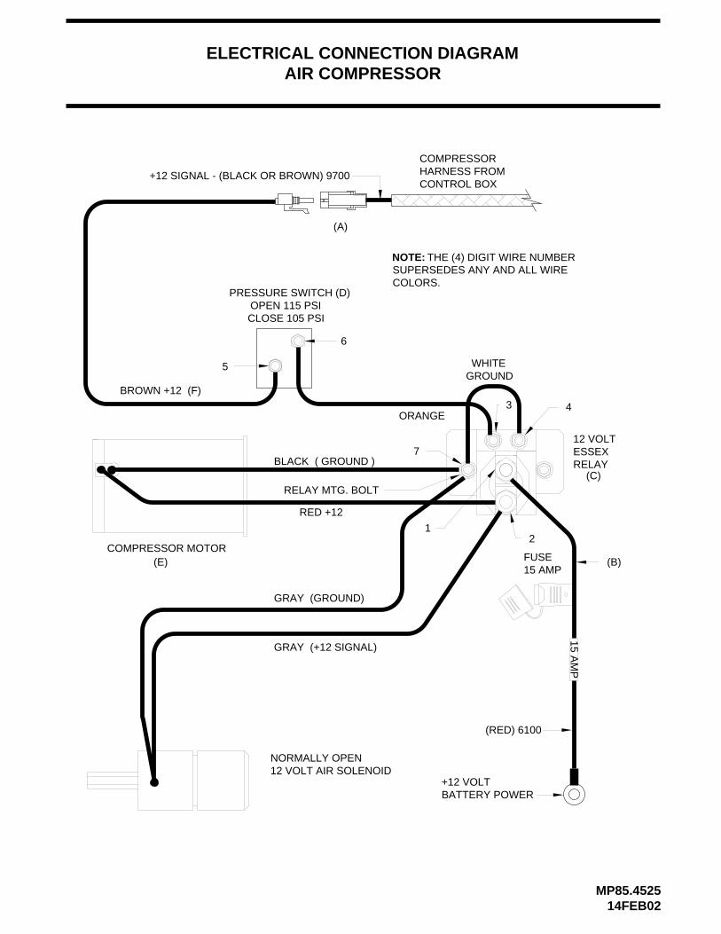
NOTE: THE (4) DIGIT WIRENUMBER SUPERSEDESANY AND ALL WIRE COLORS.
The control box sends a +12 signal to the normaly closed pre-ssure switch (1). If the pressure is low, the 12 volt relay (2) will energize and the compressor will run. The normally open air solenoid (3) will close allowing the compressor to build pre-ssure. When the pressure builds to 115 P.S.I. the pressureswitch will open, stopping the air compressor.
The normaly open air solenoid (3) will open, allowing internalpressure & moisture to bleed off. The check valve (4) will keepthe suspension air from bleeding back to the compressor. Asair pressure drops below 105 P.S.I. the compressor will start.
REAR AIR PRESS SW - LR LOWER - (PURPLE) 4600LREAR RAISE - (GREEN) 4500
RR LOWER - (BROWN) 3600RR RAISE - (ORANGE) 3500
BATTERY - (RED) 6100IGNITION - (YELLOW) 6110
PARK BRAKE SENSOR
WHITE-(GROUND)
YELLOW-LEFT SIDEBLACK-FRONTGREEN-RIGHT SIDERED-REAR
PA
RK
B
RA
KE
PO
WE
RH
AR
NE
SS
RE
AR
AIR
H
AR
NE
SS
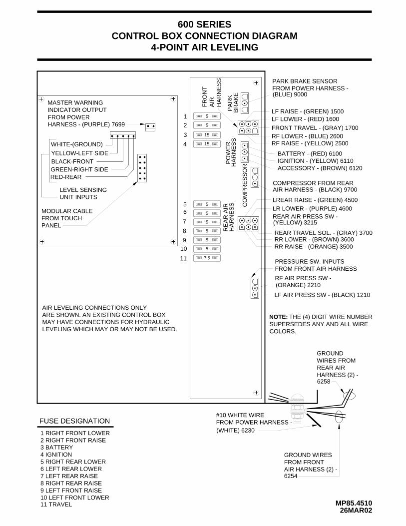
CONTROL BOX CONNECTION DIAGRAM
MP85.451026MAR02
15
15
5
5
5
5
5
5
7.5
COMPRESSOR FROM REAR
CO
MP
RE
SS
OR
1
2
3
4
56
7
8
910
11
3 BATTERY4 IGNITION5 RIGHT REAR LOWER6 LEFT REAR LOWER7 LEFT REAR RAISE8 RIGHT REAR RAISE9 LEFT FRONT RAISE10 LEFT FRONT LOWER11 TRAVEL
FUSE DESIGNATION
5
5
RF RAISE - (YELLOW) 2500RF LOWER - (BLUE) 2600
LF RAISE - (GREEN) 1500LF LOWER - (RED) 1600
FRONT TRAVEL - (GRAY) 1700
1 RIGHT FRONT LOWER2 RIGHT FRONT RAISE
#10 WHITE WIREFROM POWER HARNESS -
GROUND WIRESFROM FRONTAIR HARNESS (2) -
GROUNDWIRES FROMREAR AIRHARNESS (2) -
600 SERIES
4-POINT AIR LEVELING
RF AIR PRESS SW -
REAR TRAVEL SOL. - (GRAY) 3700
LEVEL SENSINGUNIT INPUTS
MASTER WARNINGINDICATOR OUTPUT
MODULAR CABLEFROM TOUCHPANEL
FR
ON
TA
IRH
AR
NE
SS
PRESSURE SW. INPUTSFROM FRONT AIR HARNESS
FROM POWER HARNESS -
AIR HARNESS - (BLACK) 9700
LF AIR PRESS SW - (BLACK) 1210
(WHITE) 6230
6254
6258
FROM POWERHARNESS - (PURPLE) 7699
(BLUE) 9000
NOTE: THE (4) DIGIT WIRE NUMBERSUPERSEDES ANY AND ALL WIRECOLORS.
AIR LEVELING CONNECTIONS ONLYARE SHOWN. AN EXISTING CONTROL BOXMAY HAVE CONNECTIONS FOR HYDRAULICLEVELING WHICH MAY OR MAY NOT BE USED.
(YELLOW) 3215
(ORANGE) 2210
ACCESSORY - (BROWN) 6120
MP85.452514FEB02
BLACK ( GROUND )
RED +12
GROUNDWHITE
GRAY (GROUND)
GRAY (+12 SIGNAL)
15 AM
P
+12 VOLTBATTERY POWER
NORMALLY OPEN12 VOLT AIR SOLENOID
12 VOLTESSEX RELAY
BROWN +12 (F)
ORANGE
PRESSURE SWITCH (D)OPEN 115 PSICLOSE 105 PSI
COMPRESSORHARNESS FROMCONTROL BOX
+12 SIGNAL - (BLACK OR BROWN) 9700
COMPRESSOR MOTORFUSE15 AMP
(A)
(E)
6
RELAY MTG. BOLT
7
(C)
(RED) 6100
5
4
2
3
1
(B)
ELECTRICAL CONNECTION DIAGRAMAIR COMPRESSOR
NOTE: THE (4) DIGIT WIRE NUMBERSUPERSEDES ANY AND ALL WIRECOLORS.
SEE CONTROLBOX DIAGRAM
SENSING
TRAVEL -
TRAVEL - (GRAY) 1700
RF RAISE - (YELLOW) 2500
RF LOWER - (BLUE) 2600LF LOWER -
LF RAISE -
PRESSURE SW.
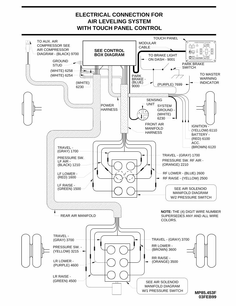
ELECTRICAL CONNECTION FORAIR LEVELING SYSTEM
WITH TOUCH PANEL CONTROL
MP85.453F03FEB99
PRESSURE SW. -
LR RAISE -
LR LOWER -
TRAVEL -
RR RAISE -
TRAVEL - (GRAY) 3700
RR LOWER -
HYD
DUMP
LEVEL
SECURELY BEFORE REMOVING TIRES OR CRAWLING UNDER VEHICLE.UNDERSTAND OPERATOR’S MANUAL BEFORE USING. BLOCK FRAME AND TIRES
CAUTION!OFF
NOT IN
TRAVEL
EXCESSSLOPE
PARK/BRAKE
STORE
RAISE
AIR
COMPUTERIZED LEVELING
TO BRAKE LIGHTON DASH - 9001
PARK BRAKE SWITCH
UNIT
MODULARCABLE
TOUCH PANEL
GROUNDSTUD
TO AUX. AIRCOMPRESSOR SEEAIR COMPRESSORDIAGRAM - (BLACK) 9700
FRONT AIR MANIFOLD
SEE AIR SOLENOIDMANIFOLD DIAGRAM
REAR AIR MANIFOLD
HARNESS
POWERHARNESS
(PURPLE) 7699
TO MASTERWARNINGINDICATOR
W/2 PRESSURE SWITCH
SEE AIR SOLENOIDMANIFOLD DIAGRAM
W/1 PRESSURE SWITCH
(WHITE) 6258(WHITE) 6254
(WHITE)6230
IGNITION -(YELLOW) 6110BATTERY -(RED) 6100ACC.(BROWN) 6120
PRESSURE SW. RF AIR -(ORANGE) 2210
SYSTEMGROUND -(WHITE)6230
(GRAY) 1700
LF AIR - (BLACK) 1210
(RED) 1600
(GREEN) 1500
NOTE: THE (4) DIGIT WIRE NUMBERSUPERSEDES ANY AND ALL WIRECOLORS.
(BROWN) 3600
(ORANGE) 3500
(YELLOW) 3215
(PURPLE) 4600
(GREEN) 4500
(GRAY) 3700
PARKBRAKE -(BLUE)9000
LEVEL SENSING UNIT
MP85.950501JUL98
SOLID MOUNTING SURFACE
SPRINGS (3)
SENSING UNIT4" DIA. X 3/4" THICK
SCREWS (3)
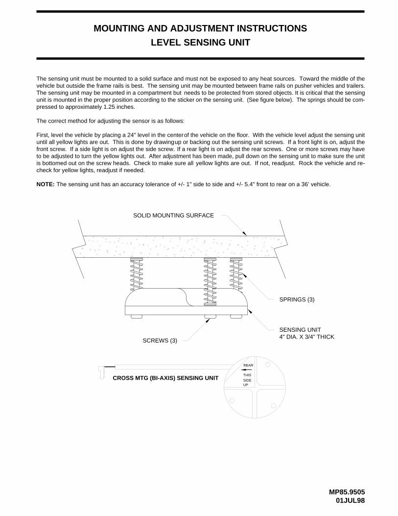
The sensing unit has an accuracy tolerance of +/- 1" side to side and +/- 5.4" front to rear on a 36’ vehicle.
MOUNTING AND ADJUSTMENT INSTRUCTIONS
CROSS MTG (BI-AXIS) SENSING UNIT
REAR
THIS
SIDEUP
NOTE:
The sensing unit must be mounted to a solid surface and must not be exposed to any heat sources. Toward the middle of thevehicle but outside the frame rails is best. The sensing unit may be mounted between frame rails on pusher vehicles and trailers.The sensing unit may be mounted in a compartment but needs to be protected from stored objects. It is critical that the sensingunit is mounted in the proper position according to the sticker on the sensing unit. (See figure below). The springs should be com-pressed to approximately 1.25 inches.
The correct method for adjusting the sensor is as follows:
First, level the vehicle by placing a 24" level in the centerof the vehicle on the floor. With the vehicle level adjust the sensing unituntil all yellow lights are out. This is done by drawingup or backing out the sensing unit screws. If a front light is on, adjust thefront screw. If a side light is on adjust the side screw. If a rear light is on adjust the rear screws. One or more screws may haveto be adjusted to turn the yellow lights out. After adjustment has been made, pull down on the sensing unit to make sure the unitis bottomed out on the screw heads. Check to make sure all yellow lights are out. If not, readjust. Rock the vehicle and re-check for yellow lights, readjust if needed.