Nfr2IEIEEOIEI FGN1HBElIliDENiIUN, · PDF fileNfr2IEIEEOIEI FGN1HBElIliDENiIUN, 980. I " . ......
78
TEST OF AN ELECTRONYDRAULIC D161TAL ACTUATOR FOR ADVAN4CED MISSI-(TC(U) FEB 80 M C TWYMAN UNCLASSIFIED AFWAL-TR-80-2001 " uuluiuuuuduu Nfr2IEIEEOIEI FGN1HBElIliDENiIUN, 980
Transcript of Nfr2IEIEEOIEI FGN1HBElIliDENiIUN, · PDF fileNfr2IEIEEOIEI FGN1HBElIliDENiIUN, 980. I " . ......

TEST OF AN ELECTRONYDRAULIC D161TAL ACTUATOR FOR ADVAN4CED MISSI-(TC(U)FEB 80 M C TWYMAN
UNCLASSIFIED AFWAL-TR-80-2001" uuluiuuuuduu
Nfr2IEIEEOIEIFGN1HBElIliDENiIUN,
980

-.0I " . ...... 5
jj _____ H2 jjj2
Fl' 112 1.
1L2 1 .6
M ! I ' ll' k' I l',,)~ ll 1 1 k IN,

AFWAL-TR-80-2001 LEVEL
0
dElF (F AN E O P4JLIC DIGITAL AC1ATR FOR V/KED MISSILE SY S
DTlC1 ELECTE !1Power Systems BranchAerospace Power Division S JUL 3 0 1980D
February 1980
TECHNICAL REPORT AFWAL-TR-80-2001
Final Report for Period September 1978 - September 1979
Approved for public release; distribution unlimited.
AERO PROPULSION LABORATORY /AIR FORCE WRIGHT AERONAUTICAL LABORATORIESAIR FORCE SYSTEMS COMMANDWRIGHT-PATTERSON AIR FORCE BASE, OHIO 45433
80 7 0o 059

_~~ ow "rz
NOTICE
When Gdvernment drawings, specifications, or other data are used for any pur-pose other than in connection with a definitely related Government procurementoperation, the United States Government thereby incurs no responsibility nor anyobligation whatsoever; and the fact that the government my have formulated,furnished, or in any way supplied the said drawings, specifications, or otherdata, is not to be regarded by implication or otherwise as in any manner licen-sing the holder or any other person or corporation, or conveying any rights orpermission to manufacture, use, or sell any patented invention that my in anyway be related thereto.
This report has been reviewed by the Information Office (O) and is releasableto the National Technical Information Service (NTIS). At NTIS, it will be avail-able to the general public, including foreign nations.
This technical report has been reviewed and is approved for publication.
MARK C. TWYMAN B. L. MCFADDENProject Engineer Acting ChiefPower Systems Branch Power Systems Branch
FOR THE COMN NDER
JAMES D. REAMSChief, Aerospace Power DivisionAero Propulsion Laboratory
"If your address has changed, if you wish to be removed from our mailing list,or if the addressee is no longer employed by your organization please notifyAFWAL/POOS ,W-PAFB, Of 45433 to help us maintain a current mailIng list".
Copies of this report should not be returned unless return is required by se-Curity considerations, contractual obligations, or notice on a specific document.AIR FORCVE56go/g July 1 0- I00

SECURITY . .ASSIFI CATION OF THIS PAGE (ft3en Date Entered)__________________
REPORT DOCUMAENTATION PAGE BFRE COMPLETINORM
Ati~ii~fta~n,7 / 2. GOVT ACCESSION NO. 3. RECIPIENT'S CATALOG NUMBER
4. TITLE (and Subtitle)T
g ,ST OF AN-ELECTROHYDRAULIC DJGITAL SeptdMM 178 - Sep' 7ATUATOR F6-VADVANCED .PISSILE -YSTEMS\O -G-.PERFORMING ORG. REPORT NUMBER
7. AUTNOA e.. S. CONTRACT OR GRAtt NUMBEWe)
J Mark,/Twyman /
9. PERFORMING ORGANIZATION NAME AND ADDRESS 10. PROGRAM ELEMENT. PROJECT. TASK
Aero Propulsion Laboratory (PODS) Progra'm EeeAF Wright Aeronautical Laboratories, AFSC Project 3145, Task 314530,Wright-Patterson Air Force Base, Ohio 45433 Work Unit 31453021
11. CONTROLLING OFFICE NAME AND ADDRESS II/ J
Aero Propulsion Laboratory (P00) )J FebynewyI4980AF Wright Aeronautical Laboratories, AFSC - 13. NUMBER OF PAGES
Wright-Patterson Air Force Base, Ohio 45433______________14. MONITORING AGENCY NAME & ADDRESS(11 different trom Controlling Office) 15. SECURITY CLASS. (of this report)
Unclassified15a. OECL ASSI FIC ATION/ODOWN GRADING
SCHEDULE
16. DISTRIBUTION STATEMENT (of this Report)
Approved for public release; distribution unlimited.
17. DISTRIBUTION STATEMENT (of the abstract entered In Block 20, it different from Report)
I8. SUPPLEMENTARY NOTES
19. K EY WORDS (Continue an reverse eide it necessary and Identify by block numb er)
Digital actuatorDynavectorHydraulic motorMissile system actuator
0. ASTRCT Conlou enr veree de if necessary end Idetill hb block number)This report des rbes the testing of a di~gital electrohydraulic stepperactuator developed by Bendix Systems Division under a previous Air Force R&Dcontract. The testing included calibration and 50 hours of durability cyclingtype tests. The actuator was designed for a stall torque of 2000-Inch poundsat a 3000 psi differential pressure. A discussion of the problems encounteredduring this program and an inspection analysis of the actuator after testingare included in this report.
DD I AN7 1473 EDI-TION OF I NOV 65 IS 0O11OLETE
SECURITY CLASSIFICATION OF THIS PACE (^,.n GaeeEnte.ed)
AFWAL-TR-80-2001
FOREWORD
This report contains the results from tests conducted on an
Electrohydraulic Digital Actuator. The work was performed in the Power
Systems Branch (POOS), Aerospace Power Division (PO0), Aero Propulsion
Laboratory, Air Force Wright Aeronautical Laboratories, Wright-
Patterson Air Force Base, Ohio, under Project 3145. Task 314530.
"Fluid Power," Work Unit 31453021, "Fluid & Mechanical Power Technoloqy
Demons tra ti on.
The work was conducted by Mr Mark Twyman during the period, January
1979 to March 1979. This in-house test was conducted in order to
verify test results received from the Bendix Corporation.
Special acknowledgment is given to Mr Harold Lee for his generous
support and assistance; also Mr Kenneth Binns for his excellent techni-
cal consultation during this program. The contributions to this pro-
gram of L. F. Mayer, Jack Silvius of Bendix Aerospace Division, and
Kamal E. Amin of Bendix Research Laboratories are hereby acknowledged
with appreciation.
Accession For
NTIS GRA& UDDC TABUnannouncedJustification-
ByDistribution/ .,
tvaility ,Codes
Avail and/orDist. spec al
, |,

AFWAL-TR-80- 2001
TABLE OF CONTENTS
SECTION PAGE
I INTRODUCTION 1
1. Actuator Motor 1
2. Transmission 4
II DESCRIPTION OF TEST RIG 6
III TESTS PROCEDURES 14
1. Static Leakage 14
2. Stall Torque 14
3. Life Test 15
IV SUMMARY OF PAST RESULTS 18
V AFWAL TEST RESULTS 21
1. Static Leakage 21
2. Stall Torque 21
3. Life Test 21
VI CONCLUSIONS AND RECOMMENDATIONS 27
REFERENCES 38
APPENDIX: 39
Bendix Research LaboratoryReport of Reaction Pin Spacer Failure
I . ... .. r.. .. hh . . . .. . . .
V

AFWAL-TR-80-2001
LIST OF ILLUSTRATIONS
FIGURE PAGE
I Actuator System Schematic 2
2 Electrohydraulic Digital Actuator
(Exploded View) 3
3 Test System Schematic 7
4 Actuator Test Stand(Power Supply, Actuator, and Torque Sensor) 8
5 Actuator Control Chassis 9
6 Dynavector Test Adapter Static Calibration 10
7 Actuator Test Stand 11
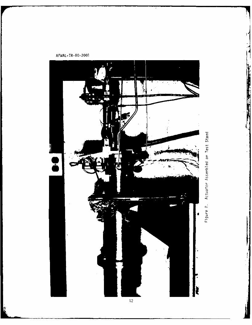
8 Actuator Assembled on Test Stand 12
9 Moog Valve 16
10 Static Leakage Test Results from Previous BendixProgram 18
11 Stepper Actuator Break-In Stall Torque from PreviousBendix Program 19
12 Static Leakage of Actuator 22
13 Stall Torque Test Data Performed Before Start ofLife Test 23
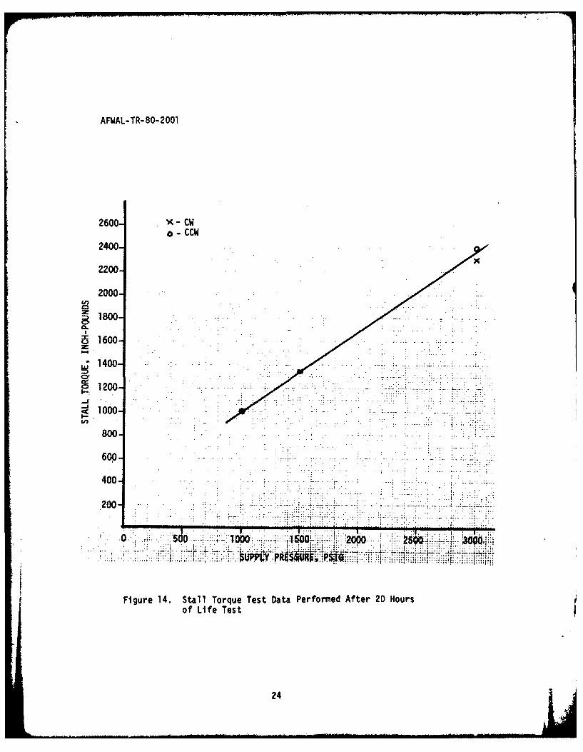
14 Stall Torque Test Data Performed After 20 Hours ofLife Test 24
15 Stall Torque Test Data Performed After Completion of
Life Test 25
16 Failed Reaction Pin Spacer 30
17 Failed Spacer, A Vane, and A Nonfailed Spacer 31
18 Reaction Pin(After 50-Hour Life Test, Taken from a NonfailedSpacer) 32
vi

'F
AFWAL-TR-80-2001
LIST OF ILLUSTRATIONS (CONTINUED)
FIGURE PAGE
19 Reaction Pin(From a Failed Spacer After 50-Hour Life Test) 33
20 Actuator Housing 34
21 Actuator Housing, Vanes, Spacers, and Rotary MotorBefore Disassembly 35
22 Actuator, Spacers, and Vanes 36
23 Actuator Output Gear 37
4vP
vii

AFWAL- TR- 80-2001
SECTION I
INTRODUCTION
The Bendix Aerospace Corporation previously developed an electro-
hydraulic digital actuator under Contract F33615-74-C-2052 (Reference 1).
A mechanical failure (reaction pin spacer) of a prototype actuator
abbreviated the testing during the Bendix program. A potential solution
was determined by Bendix and the prototype actuator was reworked with
new parts. The purpose of this program was to repeat the durability
test of this actuator to verify the actuator redesign.
The actuator characteristics used for design purposes and the
performance demonstrated by Bendix are shown in Table 1. These char-
acteristics were based on preliminary ASALM missile requirements. This
actuator concept combines a high speed orbiting motor with a high-ratio
transmission to provide high torque, low speed rotary power. The con-
trol surface is moved in discrete steps by electrohydraulic valves that
respond to digital input commands. The time required for the actuator
to move one degree in response to one command is 0.005 to 0.007 seconds.
The three major components of the actuator system are the motor, an
integral transmission, and the first stage control valves. These are
shown in Figures 1 and 2.
1. ACTUATOR MOTOR
The actuator motor is the power element or second stage of the
system. It consists of a positive displacement, very low inertia, non-
rotating vane motor. Its output is a radial force which can be rotated
at commanded stepping speeds in either direction of rotation. The
displacement chambers (Figure 1) formed by the vanes and housing expand
and collapse at the same speed as the force vector but do not rotate.

AFWAL-TR-80-2001
VALVEVALVE
FLAPPERT
ROTOR NOZZLET
1~PI 5 SPACER 7
ROTOR 1.BI Actuato SysemScemti
7 2

AFWAL-TR-80- 2001
Lit.0
AFWAL-TR-80-2 001
rhe direction of the force vector is established by applying supplypressure to four adjacent displacement chambers (for example, 1, 2, 3, 4)
while venting the other four chambers (5, 6, 7, 8) to drain pressure.
The force vector is rotated one "step" (or 45 degrees) by then pressuriz-
ing the proper vented chamber (for example, 5) while concurrently venting
the opposing pressurized chamber (1). The actuator may be rotated
through a single step while operating in the open loop mode by applying
a single digital input pulse, or it may be rapidly rotated througr a
series of steps by applying a chain of digital pulses and will stop at
the preselected position.
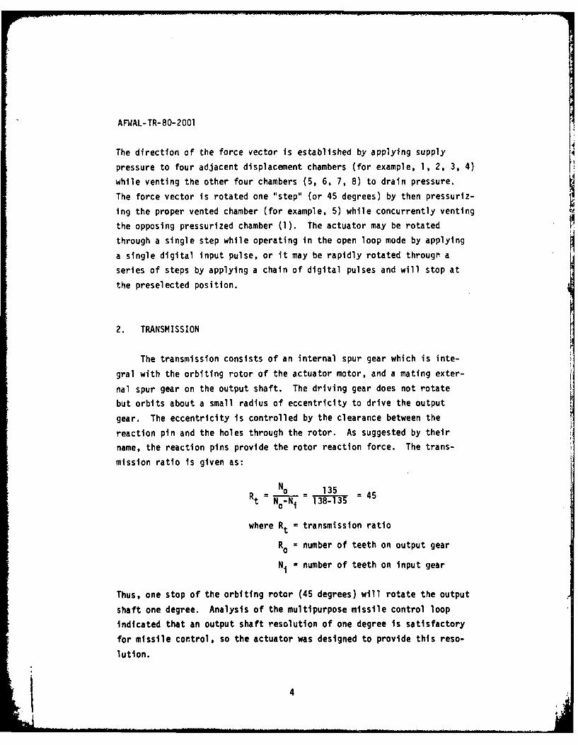
2. TRANSMISSION
The transmission consists of an internal spur gear which is inte-
gral with the orbiting rotor of the actuator motor, and a mating exter-
nal spur gear on the output shaft. The driving gear does not rotatebut orbits about a small radius of eccentricity to drive the output
gear. The eccentricity is controlled by the clearance between the
reaction pin and the holes through the rotor. As suggested by their
name, the reaction pins provide the rotor reaction force. The tranis-mission ratio is given as:
Rt= No0 135 4Rt 0-N1 138-135
where Rt = transmission ratio= ubro etho uptga
N1 number of teeth on intput gear
Thus, one stop of the orbiting rotor (45 degrees) will rotate the output
shaft one degree. Analysis of the multipurpose missile control loopindicated that an output shaft resolution of one degree is satisfactory
for missile control, so the actuator was designed to provide this reso-
lution.
I4
AFWAL-TR-80-2001
This transmission design provides an input gear pitch diameter
which is only slightly larger than the output gear pitch diameter.
Thus, a slight gear tooth deflection under load allows many gear teeth
to share the load. This same feature provides high resistance to shock
overload and minimizes dynamic loading forces. The transmission has
excellent torque transmitting capability because the dynamic tooth loads
are negligible so that the dynamic strength is nearly equal to the
static strength.
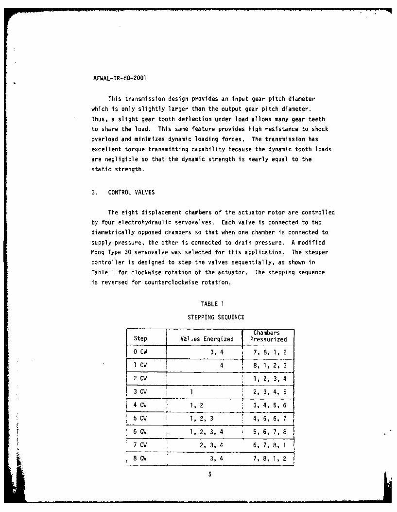
3. CONTROL VALVES
The eight displacement chambers of the actuator motor are controlled
by four electrohydraulic servovalves. Each valve is connected to two
diametrically opposed chambers so that when one chamber is connected to
supply pressure, the other is connected to drain pressure. A modified
Moog Type 30 servovalve was selected for this application. The stepper
controller is designed to step the valves sequentially, as shown in
Table 1 for clockwise rotation of the actuator. The stepping sequence
is reversed for counterclockwise rotation.
TABLE 1
STEPPING SEQUENCE
ChambersStep Vales Energized Pressurized
0 CW 3, 4 7, 8, 1, 2
l CW 4 8,1,2,3
CW 1 2, 3, 4:. 2 CW , l 2 , 3, 4
4 CW 1,2 3,4,5,6
5CW 1, 2, 3 4, 5, 6, 7
6 CW 1, 2, 3, 4 5, 6, 7, 8
Z. 7 CW 2, 3, 4 6, 7, 8, 1
8 CW 3, 4 7, 8, 1, 2
5

AFWAL-TR-80-2001
SECTION II
DESCRIPTION OF TEST RIG
All tests were performed within the AFWAL Fluid Power Laboratory.
A schematic of the test rig is shown in Figure 3. The Laboratory test
rig is shown in Figure 4.
Two pieces of equipment were designed by Bendix Corporation speci-
fically for use in this actuator program; a Dynavector Control Chassis,
and a Dynavector Test Adapter.
The Dynavector Control Chassis (Figure 5) receives, from an exter-
nal frequency generator, a square wave signal and then provides the
electric pulses to the control valves of the actuator. The Control
Chassis is designed for two modes of operation, manual or automatic.
In the manual mode, the actuator is advanced one step at a time by
pressing a step button. The direction of rotation is controlled by a
switch. The automatic mode will allow the actuator to run in a continu-
ous loop or in a cycle, with the use of a built-in limit switch, between
selected shaft positions. Commanded shaft positions are indicated on
the control panel by a digital readout.
The Dynavector Test Adapter transmits torque and inertia loads to
the actuator. The torque is developed with a torsion spring rated at
2000 inch pounds at 300 deflection. A calibration of the spring is
shown in Figure 6. Inertia plates can be installed on the adapter to
evaluate the effects of different amounts of inertia applied to the
actuator. The basic fixture has an inertia of 0.11 inch pounds/sec2 ,
2and each plate has an inertia of 0.32 inch pounds/sec
The adapter utilizes a Lebou No. 1204-200 torque sensor between the
actuator and load. A visual position indicator shows the actual position,
in degrees, of the actuator shaft. The test stand is shown in Figures
7 and 8.
6

AFWAL -TR-80- 2001
~~4J_- I- LUU
U-
cc~
L.) (A
Li I.-
LU=LL -j4
CD I-.
JLLJC)
ce-
1/J --k- CflQ)
C)- LLI
7

AFWAL- TR-80- 2001
0
4JS..
4J0

AFWAL-TR-80-2 001
ul
41
4-,
1,11, t0M)
C7
90

AFWAL- TR-80- 2001
00
C C
4-3
x 01
S a
I-
0~
S 4-d#
cl d
100

AFWAL-TR-80-2001
04-
F-4-
w S.-o
4-)E-4 u
wcZ 0.
0*"..
rA z CO11
AFWAL-TR-80-2001
ILL
c-u
12

AFWAL-TR-80-2001
Four Switching Valves are used to control the pressure of the eight
motor chambers. Each valve controls two diametrically opposed chambers.
One chamber will be at the supply pressure (3000 psi rated) and the
other chamber at return pressure. When a valve is switched, the chamber
pressures are reversed.
A modified Moog Type 30 servovalve was selected for this applica-
tion. The Type 30 is a small (approximately 1.5 inch cube) 2-stage,
4-way flow control valve that is used extensively in aerospace appli-
cations. The feedback wire that normally connects the flapper to the
second stage spool was removed (Figure 9) because proportionality is
not required. The valves, modified with a high temperature coil, are
rated at -65°F to +300'F with a 15-minute capability to 600*F.
The valves were supplied with three sets of spool end plates so
that the effect of valve capacity could be evaluated. Evaluation was
performed by Bendix Corporation. The end plates limit the spool travel
and, therefore, the maximum flow rate. With the 100% stops, the maximum
flow rate is 8 cubic inches per second. The other stops limit the
flow rate to 75% (6 in 3/second), and 50 percent (4 in3/second) of
maximum flow. Testing proved that the 50% flow capacity gave optimum
performance.
Instruments used included an oscillograph and a flow chart. The
data that was recorded is as follows: flow (inlet and outlet), torque,
and position. The examples of oscillograph recordings are labeled
accordingly. The additional data that was hand recorded is frequency,
mode, steps, and flow run time. Calibration on all instruments was
checked periodically throughout the test.
13

AFWAL-TR-80-2001
SECTION III
TEST PROCEDURES
The type of tests performed were: static leakage test, stall torque,
and life test.
1. STATIC LEAKAGE
Static actuator leakage data was taken for each of the 8 chambers
at 3000 psi supply pressure. This data is displayed in Figure 12.
2. STALL TORQUE
Supply pressure for actuator is set at predetermined test pressure.The actuator is then stepped against the torsion spring until a stall
condition is encountered. The stall condition is when the actuator
fails to move against the applied torque. This procedure was performed
for supply pressures of 1000, 1500, 3000 psi. Stall torque efficiencymay be calculated from:
T1nt b D. AP e Rt sin 0
where
b, motor length = 0.439 inch
T, output torque =2500 inch pounds
D vane seal diameter = 2.9375 inch
P, pressure difference =3000 psi
e, eccentricity =0.0234 inch
Rt, gear ratio z 45:1
p, angle of pressure vector =90 degreeswith axis of eccentricity
0.3Tit.37 2500 61.3%0.43 x .935 x3000 x 0.0234 x 45 sin 90
14

AFWAL-TR-80-2001
3. LIFE TEST
To perform the life test, the actuator was cycled +20 degrees around
zero at a rate of 140 degree/sec with a supply pressure of 3000 psi.
The maximum torque incurred is +1350 inch pound at +20 degrees. Hand
recordings were taken periodically throughout the test. The magnetic
plug installed in the return line was inspected for particles every hour.
Due to previous life test failures (Ist 24 hrs., 2nd 34 hrs.) the actuator
was disassembled and inspected after 20 hrs. of operation. After the
inspection, the actuator was reassembled and testing was continued until
the 50-hour requirement was met.
15

AFWAL-TR-80-2001
WIRI
Figure 9. Moog Valve
16

AFWAL-TR-80-2001
TABLE 2
ACTUATOR CHARACTERISTICS
DemonstratedDesign by Bendix
Hinge Moment (stall) 2000 inch-pounds 2400 inch-pounds(rated) 1333 inch-pounds 1330 inch-pounds
Vane deflection (maximum) +350 +35O
Vane rate (unloaded) 250°/sec (max) 6700 /sec(rated) 140*/sec 390°/sec
Fluid Chevron M-2V or equivalent MIL-H-5606
Fluid pressure - inlet 3400 psia 3000 psid- outlet 400 psia pressure
differential
Operating temperature - fluid -65 to +600°F No tests-65 to +550°F conducted
except roomtemperature
17

AFWAL- TR- 80- 2001
SECTION IV
SUMMARY OF PAST RESULTS
The following tests were performed by Bendix Corporation at their
research laboratory and previously reported in Reference 1. Results of
static leakage test conducted by Bendix are shown in Figure 10.
MIL-I1-SGOG HYDRAULIC FLUID, AMBIENT TEMP..003 INCH SPACER150 INCII-P1OUND OUTER SCREW TORQUE50 INCH-POUND INNER SCREW TORQUE
.5
4
3000 PSI SUPPLY.33 ZERO PSI iETURN
.20
<.1j*
0 2 3 4 5 G 7
CW STEP NUMBER
Figure 10. Static Leakage Test Results from Previous BendixProgram
184.

AFWAL-TR-80-2001
Results of Bendix's stall torque test are shown in Figure 11.
STALL TORQUE VS SUPPLY PRESSURE
2600-
2400 -__
* MIL-Il-SGOG FLUID
2200 -. AMBIENT TEMPEIATURE --
• ZEIO R:TURN PRESSURE
2000 0 CCWo, I
o o80- -/ o00
~PC./
1200 - -0 0
1000
400 l-eg
200.-
0 600 1000 1500 2000 2500 3000
SUPPLY PRESSURE, PSIG
Figure 11. Stepper Actuator Break-In Stall Torque from PreviousBendix Program
BENDIX LIFE TESTS RESULTS
Results of the first life test were unsatisfactory. During the first
life test, the actuator began to lose steps and cycle erratically. The
test was stopped and the magnetic plug was inspected. It was covered
with many particles. The life test had been run for 23.7 hours. The
19

AFWAL-TR-80-2001
actuator was disassembled and inspected. Two of the reaction pin spacers
were missing. The others showed severe deterioration. The rotor was
badly scored in spacer holes and eijacent areas. The rest of the actuator
appeared to be in normal condition.
It was concluded that the fatigue failure was due to decarburization
of the reaction pin spacers. New pins were fabricated taking special
precautions to prevent decarburization. The actuator was then reassembled
using new seals, bearings, screws, rotor, and shaft. Break-in tests were
run. The performance was essentially the same as the original.
Procedure for the second life test was the same as the first. The
life test proceeded well for 34 hours, then was stopped when a large
(0.06 x 0.09 x 0.0025 inch) chip was found in the return line. No
deterioration in performance had been detected. Total time on the
actuator was 39.2 hours. The actuator was disassembled and inspected.
The number 4 spacer was fractured into several pieces. Under magnifi-
cation, other spacers showed signs of deterioration (cracks).
Analysis of the failure resulted in a recommendation to change the
reaction pin spacer material from M-2 tool steel to VASCO wear tool steel.
Vasco tool steel has nearly equivalent compressive strength and wear
characteristics but is appreciably tougher. The actuator was rebuilt
with Vasco wear tool steel reaction pin spacers and then delivered to
the Aero Propulsion Labc )ry for performance testing. The
results of this pe 'orma; .e testing is contained in Section V.
20

AFWAL- TR- 80-2001
SECTION V
AFAPL TEST RESULTS
The following are the results of testing at AFWAL on the actuator rebuilt
by Bendix:
1. STATIC LEAKAGE
Static leakage data was taken at a supply pressure of 3000 psi usingMil-5606 hydraulic fluid at Z80*F. This test was performed before and
after the life test. The results indicated virtually no change in static
leakage performance. Data is shown in Figure 12.
2. STALL TORQUE
Stall torque test was performed before life test, after teardown
(teardown occurred at the 20th hour of life test), and after the life
test. The results are shown in Figures 13, 14, and 15.
3. LIFE TEST
The life test proceeded with no actuator mechanical difficulty,
although some other problems were encountered. A summary of test condi-
tions and results are shown in Table 3. Just after 6 hours of testing,
a fluid supply hose ruptured. It was replaced and testing was resumed.
After 11 hours, the actuator began to bypass the limit of 20 degrees
and drive to the stall condition before switching directions. This
happened several times and appeared to be an electrical problem. The
problem was corrected and the test proceeded. At the end of 20 hours,
the actuator was disassembled and inspected. No sign of deterioration
was found so the test was continued. After several hours, the return
line filter element was removed and cleaned. No metal was found, but
a large amount of fine rubber particles were removed. The rubber
particles were introduced into the system when the high-pressure hose
burst. The test was resumed (using the same filter element). The test
was completed with no sign of actuator failure.
21

AFWAL-TR-80-2001
STATIC LEAKAGE
3000 psi Supply PressureMIL-H-5606 Fluid
800F
.5
LEAKAGE .4
(GPM)
.3
.2
.I
1 2 3 4 5 6 7 8
CHAMBERNO
Figure 12. Static Leakage of Actuator
22

AFWAL-TR-80-2001
W.T i
1000
800
600
400 -
..0560 1060 15bo 2d00 2560 3060SUPPLY PRESSURE, PSIG
Figure 13. Stall Torque Test Data Performed Before Startof Life Test
23
AFWAL-TR-80-2001
2600- -c0-CCW
2400-
2200-
2000-
1800-
~1600-
u71400-
CD1200-
800-
600-
400
.200....
Figure 14. Stall Torque Test Data Performed After 20 Hoursof Life Test
24

AFWAL-TR-80-2001
2600-x -CW
2400- -.CW
2200
100-
l80o:.
.1600
-400
66 I:hOl5'0 2060 25100 3060
Figure 15. Stall Torque Test Data Performed AfterCompletion of Life Test
25

AFWAL- TR- 80-2001
TABLE 3
SUMMARY OF LIFE TEST
Hours - 50
Cycle Rate - 140 degree/sec
No. of steps - 25,200,000 steps
Average flow - 3.35 gpm
Dynamic flow - 2.65 gpm
26

AFWAL-TR-80-2001
SECTION VI
CONCLUSIONS AND RECOMMENDATIONS
CONCLUSIONS
1. The actuator met all the design requirements. The reaction pin
spacer problem appears to be solvable but has reduced the overall success
of this program.
2. The repeatability and accuracy of the actuator, without feedback,
is very impressive. The use of direct digital input without feedback
for advance missiles appears very attractive for application where
digital computers are being used for guidance and control. Also, the
capability of this approach for high temperature applications, where
null shift is a problem with conventional electrohydraulic servo's,
appears to be very attractive.
RECOMMENDATIONS
1. The following are recommended approaches to solve the reaction pin
spacer problem:
a. After heat treatment, the outside diameter and inside diameter
of the spacer should be jig ground to a fine microfinish. The spacer
housing should also be ground or lapped to ensure a smooth contact
surface between spacer and housing. The lapped contact surface should
greatly reduce fatigue caused by abrasive wear.
b. Additional flow should be supplied into the spacer area. The
leakage would lubricate and clean the contact surfaces. Again this
would reduce fatigue from abrasion (scoring, fretting, etc.).
27
AFWAL-TR-80-2001
c. Enlarge the outside diameter of the reaction pin spacer. Thiswould decrease the overstress problem encountered with Lhe spacer size
being used.
2. The testing to date has proven the feasibility of this approach.Further testing of this actuator is not recommended because of the
reaction pin problem.
Every hour throughout the test, the magnetic plug in the return
line was inspected. Several times (occurring randomly) the plug had a
small amount of very fine metal particles on it. The actuator's per-
formance did not change at these times nor at any other time throughoutthe test.
At the end of the life test, the actuator was disassembled andinspected. The number one reaction pin spacer, shown in Figures 16 and
17, was broken into four pieces. Reaction pins are shown in Figures
18 and 19. The other reaction pins and other parts of the actuator,
as shown in Figures 20 through 23, appeared to be in good condition.
The pieces of the broken pin all had sharp edges and showed no sign of
being crushed. The magnetic plug was clean after the 50th hour.
The mechanical portion of the actuator performed satisfactorily
throughout the 50-hour test except for the reaction pin spacer failure.
The fact that the pin had not been crushed seems to indicate that it
had not been broken very long. The reaction pin spacer which failed
was sent, along with two other spacers and three reaction pins, to the
Bendix Research Laboratory (BRI) for analysis. At BRI the pieces under-
went microscopic examination, hardness measurements, and EDAX analysis
procedures. The complete BRI report is contained in the appendix of
this report.
28

AFWAL-TR-80-2001
The following is an outline of some of the more critical findings
from BRL. The outer surface of the failed spacer contained a large
number of deep long cracks. These cracks originated at the outer sur-
face and propagated inward, thus, causing the spacer to fail. The
cracks found on the failed spacer indicate that the spacer was over-
stressed. Poor finish machining is the apparent cause of the abrasive
wear (scoring and spalling) on the failed spacer.
29

711
300
....... ..

A FWAL- TR- 80- 2001
Figure 17. Failed Spacer, A Vane, and A Nonfailed Spacer
31

A FWAL -TR- PO-2fLDO1
.4-
32
-- ----- ------

AFWAL-TR-80-2 001
Figure 19. Reaction Pin(From a Failed Spacer After 50-Hour yife Test)

AFWAL- TR-80- 2001i
34-

AFWAL-TP-On-' 11
-o
414ua)-c
353

AFWAL-TR-80- 2001
Cj
36,

A FWAL- TP- qO- ?Of) I
i1

AFWAL-TR-80-2001
REFERENCES
1. Jack M. Silvius. Digital Electrohydraulic Stepper Actuator forAdvanced Missile Systems, Bendix Corporation Aerospace SystemsDivision, Mishawaka, Indiana 46544, June 1978.
2. K. E. Amin, Failure of Reaction Pin Spacer on Model HL-045-UlDynavector Actuator. Bendix Research Laboratories Internal Memoran-dum, Appendtx of this report.
38

AFW4AL-TR-80-2001
APPENDIX
BENDIX RESEARCH LABORATORYREPORT OF REACTION PIN SPACERFAI LURE
39

AFWAL-TR-80-2001
Internal Bendix Research
Memorandum Laboratories
Date May 7, 1979 Letter No. Southf.eld. M-chogan
To J. M Silvius, Bendix Aerospace System Division/Mishawaka Operations
From K. E. Amin
Subject Failure of Reaction Pin Spacer on Model HL-045-U1 Dynavector Actuator
A reaction pin spacer, which failed during the 50 hour life test of theDynavector Actuator at WPAFB, was sent to BRL along with two otherspacers and three reaction pins that experienced the same te:,t foridentification of the most probable cause of failure.
A previous studyI of spacer failure (at BRL) attributed that failuv.; tostrength reduction by decarburization of the spacer during heatLtreatment. Care was then taken to avoid decarbur zAion; hwever spacerfailure was again experienced and new BRL studies determined thatfailure at that time was a result of crackinq (surfact dam.age) of spacerbore by abusive grinding (or honing) during the final machiningoperation. Replacement of the spacer material (M2 tool steel) by atougher alloy (cold worked die steel) was then recommended andimplemented. However one of the reaction pin spacer failed, and vnefollowing investigation was initiated to look into the problem orcemore. Microscopic (optical and scanning) examirlationhardnessmeasurements and EDAX were carried out on the provided pieces and thefollowing is a summary of observations:
The outer surface of the spacer which failed during the life tesi.contains a large number of deep long cracks, origlnating ori th?surface and running parrallel to the spacer axis. Evidence .fabrasive wear and some adhesive wear damage and ooo" surface f.nish(from machining) is observed, along with residue of debris patici'sand chips (Figures 2 to 6).
The failed spacer inner surface (bore) shows some surface damage inthe form of scoring, spalling (microspalling) ou;o pittirng reskiltingfrom both abrasive wear (during testing) and p.ar mnchiniing (o;ringfabrication). However, almost no cracks were found on tat sur.F.ce(Figure 7).
Both inner and outer surfaces of those spacers whicn pa:sed the lifetest show little damage and cracking, some brinelling (surfaceindentations), and contain almost no trapped particle (ordebris)(Figure 8 and 9).
#Surface of the Dynavector pin, which was in contact with the failedspacer reveals slight abrasive damage (Figure 10). The pin has a0.179 in diameter, slightly larger than the design requirement(0.165 to 0.175 in.). 40

AFWAL-TR-80-2001
Internal BniMemorandum
Date May 7, 1979 Letter No.
page 2
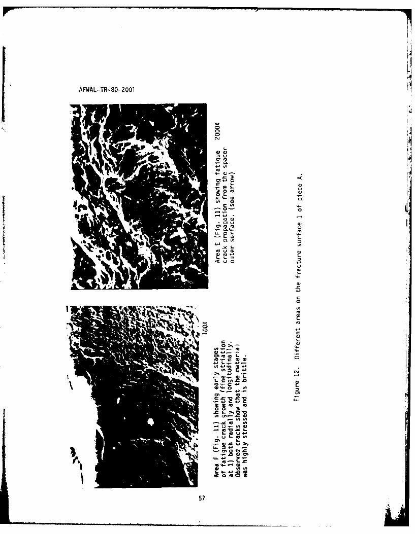
o Fracture surfaces reveal multiple crack initiation and propagationsites; initiation sites were on the outer surface and propagated byfatigue to a final brittle failure. Quasi-cleavage facets and deepcracks exist all over the fracture surface indicating still a lackof sufficient ductility combined with spacer overstressing.
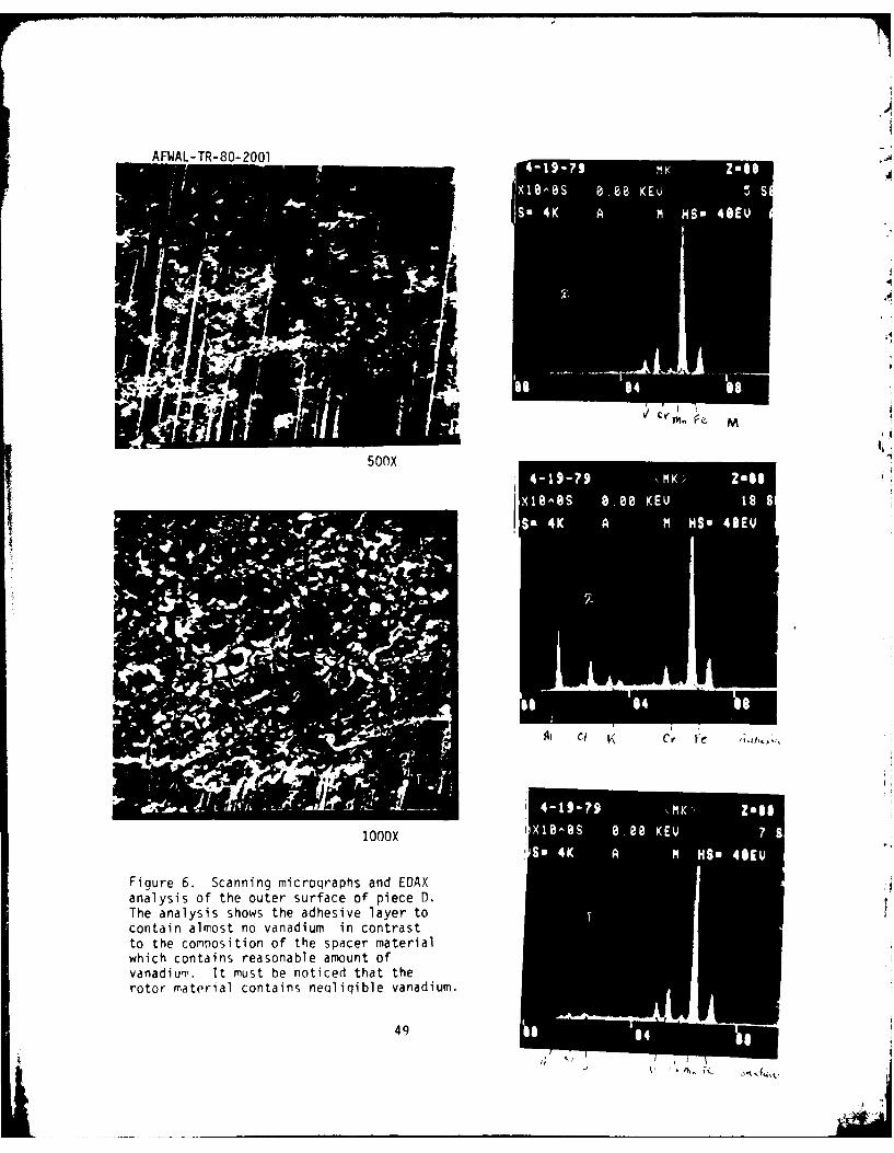
o EDAX analysis of the adhesive layer on the outer surface of thefailed spacer shows almost no vanadium (Figure 6); the spacermaterial contains about 2.4% vanadium, while the rotor containsnegligible amount of vanadium (< _6%.).
o Microstructure of all spacers (failed and not failed) is uniform andshows no evidence of either decarburization or microstructuraldefects (such as segregation, banding, etc.) (Figures 19 and 2U).
o Hardness measurements taken on different sections of both the failedand not-failed spacers yield values in the range of 49 to 56 Rc;this steel when air hardened should yield 60 Rc minimum.
Discussion and Conclusion:
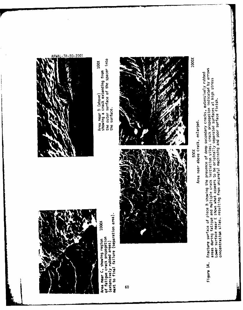
From the evidence presented so far, it appears that fracture of thespacer occurred as a result of its outer surface damage, which providedmultiple crack initiation sites and facilitated crack propagation,leading ultimately to premature failure during the life test. Damage ofthe spacer surface occured during a sequence of events starting duringthe lengthy machining and heat treatment steps (leaving scratches,scores, asperities, and high residual stress sites), and then during thelife test essentially by abrasive wear, as well as by some adhesivewear, of any trapped particles during relative motion (sliding) of rotorand spacer (opening new cracks and enhancing propagation of existingcracks). Those trapped particles probably existed on the originalsurfaces (rotor and spacer) as a result of insufficient cleaning aftervarious processing (machining and heat 'treatment) and/or formed bybreaking either surface-asperities and debris formation (enhanced byrough surface finish, oxidation and differnece in relative hardness ofthe sliding surfaces) during the life test. It appears that theadhesive layer composition is closer to that of the rotar material.The inner surface of the rotor was not available for examination.
41

•AFWAL- TR-80- 2001
Internal OendixMemorandum
Date Letter No.May 7, 1979
page 3
Recommendation:
1. The contacting surfaces (rotor and spacer) must be fabricated to asmooth surface finish, and thoroughly cleaned following the lengthymachining and heat treatment step, so as to minimize the presence oftrapped particles and avoid surface damage by wear.
2. Again, final machining should be carried out gently and in no wayshould result in surface scoring, and damage, since fatigue life ofthe spacer is very sensitive to its surface condition.
3. During the heat treatment, triple tempering in air might be replacedby a double treatment in an inert atmosphere, and hardness values60 Rc or higher should be achieved (this also provides the desiredaloy high compressive strength).
Kamal E. Amin
KEA/pkf
cc: P. C. BeckerM. H GardonW. H. GruberL. L. HartterK. LawsonL. F. MayerS. K. Rhee
42

AFWAL-TR-80-2001
Internal BendixMemorandum
Dote mlay 7, 1979 Letter No.
page 4
References
1. J. H. Tarter, "Investigation of Failure of Reaction Pin Spacer onModel HL-045-U1 Dynavector Actuator," BLR/TM-77-8492 (August 1977)
2. S. Ganesh "Failure Analysis of Reaction Pin Spacer on ModelHL-O4b-UI Dynavector Actuator", BRL/TM-77-8514 (September 1977)
434

AFWAL-TR- 80~ 2001
a~ '.-UoJ
C-r
C
L
-t
aJ
(~2 ~L
I- ~ ~-
C
a
44

AFWAL-TP-RO-200I
i l '
Crack area A above IOOX -Crack area B ahove5,
I Figure 2. Outer surface of pin spacerpiece A (of Fig. 1), showina the presenceof deep long cracks running parrallel tothe spacer length. Evidence of abrasivewear and poor initial surface finsih(machining) is observed, along withthe presence of debris and chips.
-1
piec A o45.1) hw tepeecof depln rcsrnigprallt

AFWAL-TR-8O-2OO1
U~v)
4-,
41
0
Ln
.4-
%J -
n4 c,
ML~

AN AFA-TR-80-200
ccM
. a
00
LCL
*0A
4J4S--
40-C
vi0
E 0
0
'-CL
4-0
3: ICD 4 C
EOkO(
C"-
o o c4J4-0
(U CL In
CD- 0 A
47 O
AFWAL-TR-80- 2001
0CC)C
cnV
4J3
fa,
u a,
0 U >
rI.
,A 01
00 4A 3
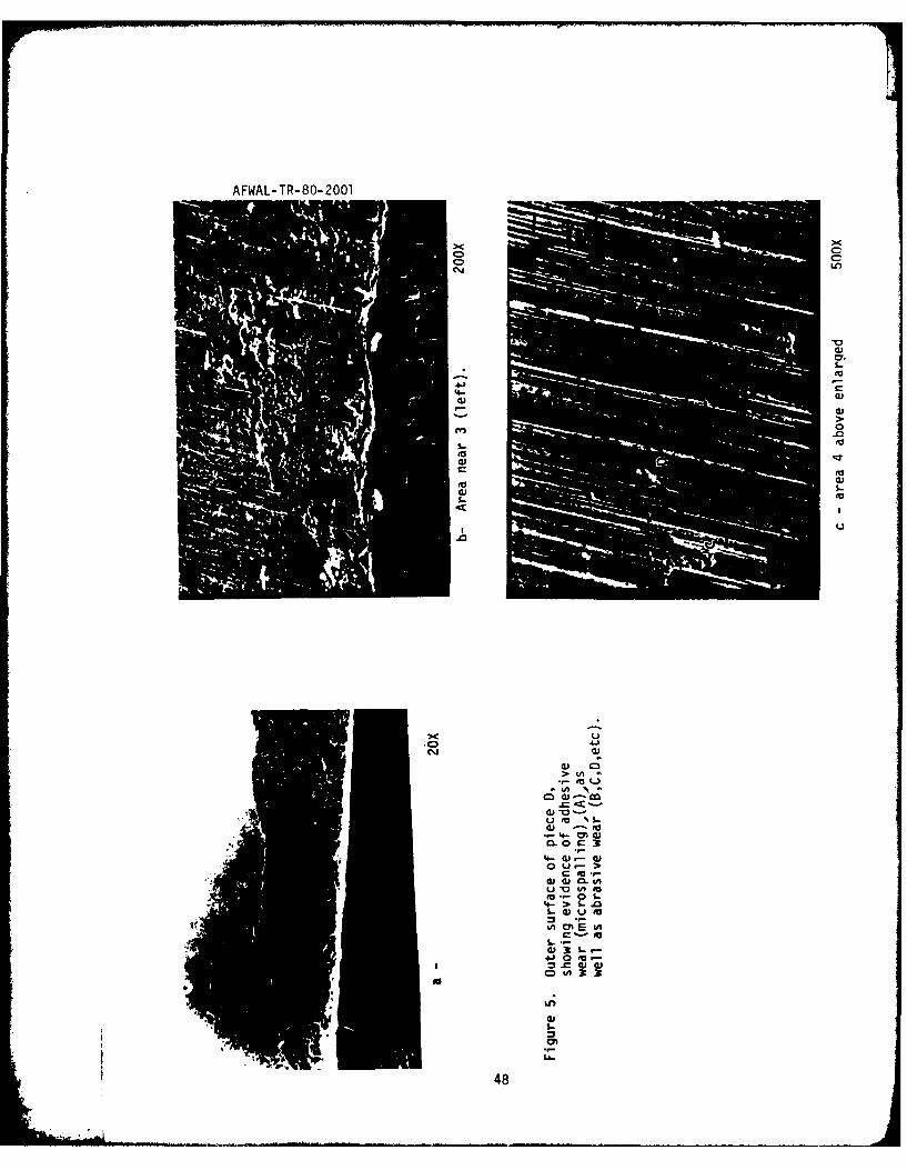
48 0-0
AFWAL-TR-80-2001
~ ~ M
50OX
Ai K
I O0 0 X 1 ." O -e s 0. [ ' 0 .. V 7l 9!
1AI 4lK CA M~ M~ 4
Figure 6. Scanning micrographs and EDAXanalysis of the outer surface of piece D.The analysis shows the adhesive layer tocontain almost no vanadium in contrastto the composition of the spacer materialwhich contains reasonable amount ofvanadium. It must be noticed that therotor material contains neqliqible vanadium.
4 14

AFW L-TR-80-2001
LO~ Ln
-1 41L) 41
4-
C Lr-L
0 to
-
4.- '0
C .
L) C:Cto .04- S.
LLO
V)3
c X
t-
MA 0M4-C:
CC: 1
CX %M 4-'
500

AFWAL-TR-80-2 001
2QOX
.... f7
500 X
Figure -8. An example of the inner surface of those pin-spacers which passed the lifetest with no failure. Brinellinq or surface indentations are observed,
probably caused by debris formed from the contacting surfaces durina testina.
The extent of damage observed here is far less than that of the failed spacer
inner surface.
51

AFWAL-TR-80-2001
•t -
dr-
.4-- 1+-'
7..0
(a m4" -
- ci
LO o) .- 0 O
4J. .r-.l w
"o wo-
-- 41 04-)
u m 0
4) 4jd 0
• ' " ... ... c- .o
4,- J U
41 0 E-C 0o 0
4A U C
W
52

AFWAL-TR-80-2001
CDc'J
Vi
k. t4A 4I
.4- 1
ilk.
4=) E
4-0 S.-
o v * 0=.-
V) C C7 -0
3: 0~O ~
0J 0 >
**4- 4-J >
C U C C
4- 4- 0)U-~ tAO 03
53 ~t= .

AFWA- R-.- 1
c a,
U~ 4-) V) Q)C 4
CL .C
9 LL,- -a
a, 2
IP 41
%4- bi
uu )
L/) u
e%3 U )
cu c
0CL

AFWAL-TR-80-2 001
.0C
C0 4
4.- u c mLLC0 4-
m. . 3
C -C
M 00W~~ 4-a) s
S-~@ 44-)4C VIP 4Ju
4~) 4.) 4-)E
C) ic IA-- 4-) 4
CL 10 .4J 3 -OU~ n S- -Ju V
to0C fa lC
C- v
3ea 0 cA-
0'4-c I4-
*- u -4 4 u -
- t EU 4.1 Mu
c.4-I".0 In- E
to- C - =4
f u to Eu E4 -
--
w 0 4u.
55

AFWAL-TR-80-2001
cu 0
C 0'4-
CLCu 00
0
4-4J
vdi
00.d)4r-4-
4)L- to"4- to 4-
CU .- S-0
5.- IA
.8 C"; A Q
CA)L 0(U ~ ~ I- CL4 Cmr
4.3 U 4- 4:-'
o u 0- 0 3d3-4n m = .. 4
M L.- 0 S- ;j - 0 aL.-4- *.- W o V.t
(U M4. 4-3.' 0
4 C U. 4) 0W (
-e in0 to-W--o ~ ~ ~ t %-3C)in
56
AFWAL-TR-80- 2001
4-L
3o
1-4 4J
fa cu
CL 4-
0 S-
CL Ln
ui (A
cu a)
4Vi
0
et)
Cl-4
4J 14- - 4D4A 41 4J
57 C

AFWAL-TR-80-2001
3
1
-
0
.1-
L. 4
4J. > a.4. 4) 4-)
aj '
rU mE U 0.0
L.a sl La)
0 a) u
oJ 004-
LL.
(.. = 4J 4J
to
U-
58

AFWAL- ;R-8o-2oO1
b A
S- 41
s- 43
41to4~ 0-
ol U 4
00 u
a) C
U(O
0
4.1
UU
05
AFWAL-TR-80- 2001
4- CL
o cu0= .
1.-U 0 W
Sm0. (. 'A
m, 'C- s t
fo a Lt
w0. 0 w w w.CS00 --
M > C- -0 'A
CA +1 4J t.- - CL a
tu fa 4-
0~ S.o to Cf L00- C0
03-S~~.C .-
0 r_ 0.s-0 0
S- C 0
S- 4A U
L Co
S-Co4
4 -0 0 LA
r- 3- =4-
to~~ 0.4-SW'
0~. U G - CA~m 4- ~ 1C
4-)w
o 06MIV~~~ moL 0 IA 4
c' 0 4.)w
004-
0*.- 0
+A 0 4A '~ 4
x 6

AFWAL-TR-80-2001
0
.4~)
C
(-3
S.-(-3
4-0
(A03C
- - 0C N
30-c(A
5-
(-33
U,
a)9-4
C)
4-,
4-0
(2
C)
U
0~ 05-
4- 5-
a)(JO
(4-5-
U, 0~0
a)a5-c
4-, 0U05--c
~~0
30 5--03
0)5-
61

AFWAL-TR-80-200lf1
4- S-
3n o
eL U
CLC 00 2
LI) 4J 4-' 0
CCp
'AA -' 4-. <)
S4-' 4-. -C 1-C
4--C EW
0 3:
40 4- S 0
4-2 0( . C C'. O
4-) 3 cm -1O4-' 0 MUf L01W
.00 0t (D Cvc:2 0
UJ 0 4-
'4--04-
.2)4- S
4- CL
4J2) 0
d) C0 0
4620 .

AFWAL- TR- 80-2001CD0'
CC
4--
w s s -- .
S.-
U -
w 0
U4-
404
(0U0
lowo
4-'4-3
CL 4-'GO
4- ea4'
4- .o 4- a) .0 0
S-.- -
0)0
CUm
LL. 0 Q)
C- U 41 +Ln. cU
lk0.0Lc- -'
03

AFWAL-TR-80-2001
4-4
C.
, 4..
a 'C
a Um-4.. - /'aC-
to@ aj
06 d0
al 0)
aS-
I..
'co,
'Vte
CO A
co 4-j 41
ti
64n
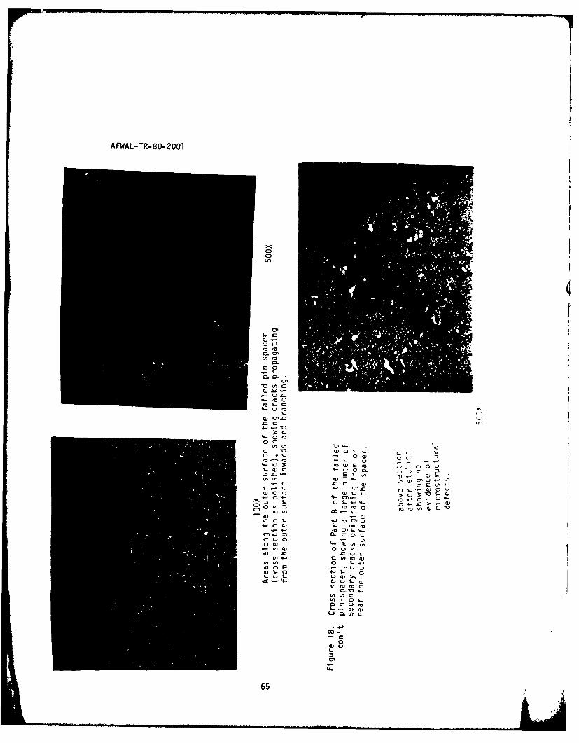
AFWAL-TR-80-2001
Ln
a -
a0
a) -C
S.-c
S-C
in '- 4-04
0 CT,
0.J~r0
ea M S-4~3: , .E -CCUO-
0 A 4
CL 44->< M-US''o L
a)S Ln E C
* 1.
cmcW 4- "
L- u u
0 S
65
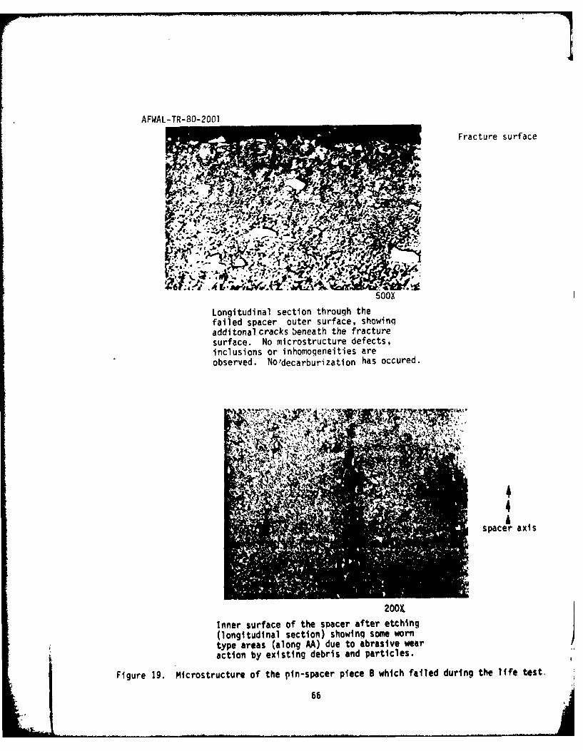
AFWAL-TR-80-2001
Fracture surface
1Yo.
J6--
500X
Longitudinal section through thefailed spacer outer surface, showingadditonal cracks beneath the fracturesurface. No microstructure defects,inclusions or inhomogeneities areobserved. No'decarburization has occured.
U44,4
Aspacer axis
200X
Inner surface of the spacer after etching(longitudinal section) showing some worntype areas (along AA) due to abrasive wearaction by existing debris and particles.
Figure 19. Microstructure of the pin-spacer piece B which failed during the life test.
66

AFWAL-TR-RO-2001
00
00
S.-
rft C44-00
0 5.-4n44- 44-
E) E
0104-) _ 101
a0 cu
0
CD I
CA 0
m 4-'(A
00CA 0 u4J 0 0.u
~L U)
0 4 -'
4-J 4- L
00.CfaS.
0 1
- 0-
-67

AFWAL-TR-80-2001
Longitudinal section through a 500X
pin spacer which did not failduring the life test, showingneither metallurgical normanufacturing defect.
SONKFigure 20 con't. Longitudinal and crosssections through one of the providedpin-spacers which sustained the life testwith no failure.
68OU.S.Government Prining Office; 1980 - 657-064/771