NFPA No..77--i977 · PDF file1-3.2 Static Spark shall mean an impulsive discharge of ......
30
SE-I COMMITTEE PERSONNEL AND VOTE STATEMENT Report of the Committee on Static Electricity Richard D. Stalker, Chairman Xerox Corp., Stamford, CT 06904 (rep. NFPA Industrial Fire Protection Section) R. D. Boddorff, Institute of Makers of Explosives K. M. Carlisle, Manufacturing Chemists Assn. C. W. Conaway, Industrial Risk Insurers R. B. Fuller, American Mutual Insurance Alliance H. F. George, Technical Assn. of the Graphic Arts D. L Ha/l, Millers Nat'l Federation C. F. Hedlund, Factory Mutual Research Corp. O. W. Johnson, Palo Alto, CA • R.J. Kunz, 3M Company E. L. Litchtield, 13ureau of Mines, U.S. Department of the. Interior A. C. Lloyd, Int'l Fabricare Institute J. F. McKenna, American Petroleum Institute J. E. Owens, Instrument Society of America Dr. A. F. Robertson, Fire Protection Section, Nat'l Bureau of Standards E. J. Sehl~r, Underwriters Laboratories Inc. "B. Sperm,an, M & M Protection Consultants J. It. warren, American Petroleum Institute Dr. J.F.I. ~ick, American Society of Anesthesiologist~ Alternates W. L. Bulkley, Amoco Research Center Lawrence H. Foamier, American Mutual (Alternate to J.H. Warren) Insurance Alliance (Alternate to R. B. Fuller) W. A. Rand, Industrial Risk Insurer's (Alternate to C. W. Conaway) ThA list ~ eptesent* the membershtp at the lime the Committee u~ts balloted on the text o/this edition. Since that time, change.s in the membership may have occurred. The Committee on Static Electricity presents for official adop-. tion the report on revisions to the Recommended Practice on Static Electricity, NFPA No. 77. This report has been .submitted to letter ballot of the Committee which consists of l 9 voting members, Ofwhom 15 have voted affirmatively, and 4 have not returned ballots. Messrs. Boddorff, Carlisle, Hail and Warren have not returned ballots. GENERAL 77-5 Recommended Practice on Static. Electricity- NFPA No..77--i977 Chapter 1 General / "1-1 Purpose. 1-1.1 Thepurpose of this recommended practice is to assist •in reducing the fire hazard of static electricity by presenting a -discussion of the nature and origin of static charges, the general methods of mitigation and recommendations in certain specific operations for its dissipation. 1-i.2 Static electricity is often the i.gnition source for an ignitible mixture, an operating problem in industry or an an- noyance to some individuals. _ 1-2 Scope. 1-2.1 This publication covers methods for the control of static electricity for the purpose of eliminating or mitigating its fire hazard, except as provided in 1-2.3 below. 1-2.2 Chapters 5 through 8 cover the common commercial and industrial operations where the presence of static is a hazard. Static is generated in many other circumstances where its accumu- lation does not constitute a direct fire or explosio n hazard. Some of these occurrences may'be mentioned in passing but they are not the primary concern of this publication. 1-2.3 The prevention and control of static electricity in hospital operating rooms or in areas where flammable anesthetics are administered are not covered by this publication but are covered in the Standard for the Use of lnhalation Anesthetics, NFPA No. 56A. 1-2.4 Lightning is not covered by this publication but is covered in the Lightning Protection Code, NFPA No. 78. • 1-3 D~finitigns (see also Appendix A). 1-3.1 Ignitible Mixture shall mean a vapor-air, gas-air, dust-air mixture or combinations of these mixtures which can be ignited by a static spark. ,IL
Transcript of NFPA No..77--i977 · PDF file1-3.2 Static Spark shall mean an impulsive discharge of ......
SE-I COMMITTEE PERSONNEL AND VOTE STATEMENT
Report of the Committee on Static Electricity
Richard D. Stalker, Chairman Xerox Corp., Stamford, CT 06904
(rep. NFPA Industrial Fire Protection Section)
R. D. Boddorff, Institute of Makers of Explosives
K. M. Carlisle, Manufacturing Chemists Assn.
C. W. Conaway, Industrial Risk Insurers R. B. Fuller, American Mutual Insurance
Alliance H. F. George, Technical Assn. of the
Graphic Arts D. L Ha/l, Millers Nat'l Federation C. F. Hedlund, Factory Mutual Research
Corp. O. W. Johnson, Palo Alto, CA
• R.J. Kunz, 3M Company
E. L. Litchtield, 13ureau of Mines, U.S. Department of the. Interior
A. C. Lloyd, Int'l Fabricare Institute J. F. McKenna, American Petroleum
Institute J. E. Owens, Instrument Society of America Dr. A. F. Robertson, Fire Protection Section,
Nat'l Bureau of Standards E. J. S e h l ~ r , Underwriters Laboratories
Inc. "B. Sperm,an, M & M Protection Consultants J. It. warren, American Petroleum Institute Dr. J.F.I. ~ i c k , American Society of
Anesthesiologist~
Alternates W. L. Bulkley, Amoco Research Center Lawrence H. Foamier, American Mutual
(Alternate to J.H. Warren) Insurance Alliance (Alternate to R. B. Fuller)
W. A. Rand, Industrial Risk Insurer's (Alternate to C. W. Conaway)
ThA list ~ eptesent* the membershtp at the lime the Committee u~ts balloted on the text o/this edition. Since that time, change.s in the membership may have occurred.
The Committee on Static Electricity presents for official adop-. tion the report on revisions to the Recommended Practice on Static Electricity, NFPA No. 77.
This report has been .submitted to letter ballot of the Committee which consists of l 9 voting members, Of whom 15 have voted affirmatively, and 4 have not returned ballots. Messrs. Boddorff, Carlisle, Hail and Warren have not returned ballots.
GENERAL 77-5
Recommended Practice on
Static. Electricity- NFPA No..77--i977
Chapter 1 General
/
"1-1 Purpose. 1-1.1 Thepurpose of this recommended practice is to assist
• in reducing the fire hazard of static electricity by presenting a -discussion of the nature and origin of static charges, the general methods of mitigation and recommendations in certain specific operations for its dissipation.
1-i.2 Static electricity is often the i.gnition source for an ignitible mixture, an operating problem in industry or an an- noyance to some individuals. _
1-2 Scope. 1-2.1 This publication covers methods for the control of
static electricity for the purpose of eliminating or mitigating its fire hazard, except as provided in 1-2.3 below.
1-2.2 Chapters 5 through 8 cover the common commercial and industrial operations where the presence of static is a hazard. Static is generated in many other circumstances where its accumu- lation does not constitute a direct fire or explosio n hazard. Some of these occurrences may'be mentioned in passing but they are not the primary concern of this publication.
1-2.3 The prevention and control of static electricity in hospital operating rooms or in areas where flammable anesthetics are administered are not covered by this publication but are covered in the Standard for the Use of lnhalation Anesthetics, NFPA No. 56A.
1-2.4 Lightning is not covered by this publication but is covered in the Lightning Protection Code, NFPA No. 78.
• 1-3 D~finitigns (see also Appendix A).
1-3.1 Ignitible Mixture shall mean a vapor-air, gas-air, dust-air mixture or combinations of these mixtures which can be ignited by a static spark.
, I L

77-6 ,STATIC ELECTRICITY
1-3.2 Static Spark shall mean an impulsive discharge of electricity across a gap between two points not in contact.
1-3.3 Bonding and Grounding are defined in Chapter 3 as the act or process of applying or affixing a bond or ground connection between two objects.
1-3.4 The words Bonded or Grounded, as they are used in the text, inust be understood to mean either that a bond or ground as defined has been deliberately applied, or tha t ' an - electrically conductive path having a resistance adequately low for the intended purpose (usually 10 6 ohms or'less) is inherently present by the nature of the installation.
1-4 Introduction.
1-4.1 The term "static electricity," as usi~d in this publica- tion, "shall mean electrification of materials through physical contact and separation, and the various effects that result from the positive and negative charges so formed - - particularly where the y..constitute, a fire or ex p losion hazard. The generation of static electricity cannot be prevented, absolutely, because its intrinsic origins are present at every interface.
1-4.2 The development of electrical charges may not be in itself a potential fire or explosion hazard. There must be a discharge or sudden recombination of separated positive and negative charges. In order for static to be a source of ignition, four conditions must be fulfilled:
(a) There must first 0fall be an effective means of static generation,
(b) There must be a means of accumulating the sepa- rate charges and maintaining a suitabl~ difference of electrical potential, (c). There must be a spark discharge of adequate- energy, and (d) The spark must occur in an ignitible mixture. 1-4.3 The accumulation of static charges may be prevented
under many circumstances by grounding or bonding, by humid- ification, or by ionization. These means and their functions will b e discussed in Chapter 3.
1-4.4 Common sources of static electricity include: (a) Pulverized materials passing through chutes or pneumatic conveyors,- •
"GENERAL 77-7
(b) Steam, air, or , gas flowing from any opening in a pipe or hose, when the steam is wet or the air or gas stream contains particulate matter, (c) " Nonconductive power or conveyor belts in motion, (d) Moving vehicles, and (e) Motions of all sorts that involve changes in relative position of contacting surfaces, usually of dissimilar liquids or solids. 1-4.5 The object of most static-corrective measures is to
provide a means whereby charges separated by whatever cause' may recombine harmlessly before sparking potentials are at- tained, or ~o avoid spark gaps where harmful discharges could . occur.
1-4.6 If hazardous static conditions cannot be avoided in certain operations, means must be taken to assure that there are. no ignitible mixtures ~at points where sparks may occur..

77-8 STATIC ELECTRICITY
Chapter 2 Generation and Accumulat ion of Static Electricity
2-1 General.
2-1.1 TO the average person the words "static electricity" .wmit~ mean either a noise in the radio receiver which interferes
good reception or the electric shock experienced when touching a metal object after walking across a carpeted floor or sliding across the plastic seat cover in an automobile. Some p e o p l e also have experienced mysterious crackling noises and a tendency for some of their clothing to cling or st.ick tightly together.when wool, silk, or synthetic fiber garments are worn. Nearly eyeryone recognizes that these phenomena occur mainly when the atmo- sphere is very dry. To most people they are simply an annoyance.
2-1.2 The word "electricity" is derived from the ancient Greek work "elektron" - - meanirig amber - - for'it was with this substance that the phenomenon of electrification was first ob- served. For centuries "electricity" had no other meaning than the property exhibited by some substances, after being rubbed with a material like silk or w0ol, of being able to attract or repellight- weight objects. Stronger electrification accompanied by luminous effects and small sparks was first observed about 300 years ago by yon Guericki~. In comparatively recent times, when the properties. of flowing eleiztricity were discovered, the word "static" came into
"use as a-means of distinguishing the old from the new. The implication that such electricity is always at rest is erroneous; it is when it ceases to rest that it causes the most concern.
2-1.3 F6r the sake of simplicity, one may imagine electricity to be a weightless and indestrtictible fluid which can move freely through some substances; such as metals, that are called "conduc- tors," but can flow with difficulty or not at all through or over the surface of a class of "substances called "nonconductors" or "in- sulators." This latter group includes: gases, glass, rubber, amber,. resin, sulfur, paraffin, and most dry petroleum oils and many plastic materials. When electricity is present on the.surface of a nonconductive body, where it is trapped or prevented from escaping, it iscalled static electricity. Electricity on a conducting body which is in contact only with nonconductors is also pre- vented from escaping and is therefore nonmobile or "static." In either case, the body on which this electricit)~ is evident is said to be "charged.'.'
I
GENERATION AND ACCUMULATION 77-9
2-1.4 The charge may be either positive (+) or negative ( - ) . At one time it was thought that the two charges were two kinds of electricity and that in a neutral' (uncharged) body they were present in exactly equal amouots. Now it Is known that there is actually only one kind of electricity', although it is described by many adjectives. It is manifested when some force has abnormally separated a few of its positive and negative constituents. 'These entities are components of all atom~, the outer electrons ( - ) and the inner, nuclear ,protons (+). Curiously, a surface that has an excess or deficiency of one electron in every 100,000 atoms is very strongl), charged.
2-1.5 It is true, however, that in a neutral Or uncharged body the tWO entities are presentin exactly equal amounts. Work is required to separate positive and negative charges. Electricity, therefore, is sometimes referred to as a form of energy produced by expenditure of energy in some other form, such as mechanical, chemical, or thermal. Likewise, when electrical energy (a better term) is expended, its equivalent appears in one or the other of these other torms.
2-1.6 Electrons are free to move from one molecule to another in conductors but the proton, in the nucleus of the atom, cannot move appreciably unless the atom moves. Therefore , in solids, only the electrons are mobile; in gases and liquids both are free to move.
2ol.7 The stable structure of the atom shows that unlike charges attract; conversely, like charges repel. It follows that a separated charge will be self-repellent-and will reside only on the surface of a charged body. If the body were a perfect-insulator or perfectly insulated, the charge would remain indefinitely. How- ever, there are no perfect insulators and isolated charges soon leak away to join their counterparts and thus bring about neutral- ization, the normal state (also see 3 - 3 ) . .
2-i.8 Static electricity then is the set of phenomena as- sociated with the appearance of an electric charge on the surface of an insulator or insulated conductive body. It is "generated v usually bythe expenditure of mechanical work, although we must remember that in this seine generated means "liberated" or made
.alive - - electricity cannot be created. Somewhere, possibly- "grounded" but as close as conditions will allow there will be an exactly equal opposi techarge - - its cotmterpart. This concept is extremely important.

77-10 STATIC ELECTRICITY
2-2 Generation. 2-2.1 When two bodies, particularly of unlike materials, are
brought into intimate contact, there is likely to be a redistribution of electrons across the interface, and an attractive force is estab- lished as equilibrium is achieved. When the bodies are separated, work must be done in opposition to these attractive forces. The expended energy reappears as an increase in electrical tension or voltage between the two surfaces. I fa conductive path is available, the charges thus separated will reunite immediately. If no such Pnath is available, as would be the case with insulators, the potential
crease with separation may easily reach values o f several thousand volts.
2-2.2 A free charge on an insulated conductive body is mobile, and the entire charge can be drained o f fby a single spark. On the other hand the charge on the surface of an insulator is relatively immobile, so that a spark from its surface can release the charge from only a limited area, and will usually not involve enough energy to produce ignition.
2-2.3 Like charges repel each other and unlike charges attract because of forces resident in the electrical fields that surround them. These forces have a strong influence on nearby objects. I f the neighboring object is a conductor it will experience a.separation of charges by induction. Its repelled charge is free to give or rece~ye electrons as the case may be; if another conductor is brought near, the transfer may occur through the agency of a spark, very often an energetic spark.
2-2.4 When the inducing charge is moved away from the insulated conductor, there follows a reversed sequence of events, and sparks may result. Thus, in many situations, induced charges are far more dangerous than the initially separated ones upon which they are dependent .
2-2.5 If the object close to the highly charged nonconduc- tor is itself a nonconductor, it will be polarized, that is, its constituent molecules will be oriented to some degree in the direction of the lines of force since their electrons have no true migratory freedom. Because of their polarizable nature, in- sulators and noncondu.ctors are o f ten called dielectrics. Their presence as separating media enhance the accumulation of charge.
G E N E R A T I O N AND A C C U M U L A T I O N 77-11
2-3 Ignition Energy. 2-3.1 The ability of a spark to produize ignition is governed
largely by its energy, which will be some fraction of the total -stored energy. Stored energy may be calculated conveniently by means of the formula ½ CV 2 x 10 -9 where V is the potential in volts and C is the capacitance in picofarads and the energy is" in millijoules or thousandths of a watt-second.
2-3,1.1 Tests have shown that saturated hydrocarbon aSes and vapors require about 0.25 millijoule of stored energy r spark ignition of opt imum mixtures with air. It has been
shown further that static sparks arising from potential differ- ences of less than 1500 volts are unlikely to be hazardous in these mixtures because of the short gap and heat loss to the terminals~
0.5 For these minima the capacitance would be C = ~ x 109 or 222 picofarads.
2-3.1.2 Thus a spark from a charged conductor the size of a large man might be hazardous if the voltage was a little n~ore than 1500 volts and the spark occurred between small electrodes. Five thousand volts would be dangerous if the capacitance was 20 picofarads or more. For assurance of safety with.a 10,000-volt spark in an explosive hydrocarbon-air mixture, the capacitance of
0.5 the charged conductor would have to be noticeably less than ~- x 109 = 5 picofarads: an isolated object the size of a baseball charged to a potential of 10,000 volts could be regarded as hazardous with spark electrodes of almost any shape. On this basis, a 20,000-volt spark would requl]-e a storage capacitance of 1¼ picofarads or a charged electrode about the size of a large marble or a 20-penny nail. The spark in air would be at least ¼ in. long.
2-3.1.3 However, as sparks become considerably longer than the quenching distance (about 1/16 in. to 3/32 in. for the most easily ignited hydrocarbon-air mixtures), the required total energy increases somewhat in proportion to th~ excess of spark length ovei- the diameter of the necessary critical flame volume. This in turn may require somewhat gi-eater capacitance than indicated above.
2-3.2 . When some portion of an extensive nonconductive surface, such as an oil surface, acquires a charge density of 3 x 10 -9 coulombs per square centimeter, the potential gradient there will exceed the dielectric strength of air (about 30,000 volts

7 7 - 1 2 STATIC ELECTRICITY
per cm) and small brush discharges or corona may appear: These serve to make the region conductive and, if the charging process is adequate, a subsequent spark from mls conaucnve surface area may have enough energy to ignite a flammable vapor-air mixture.
2-3.3 Experiments at atmospheric pressure with plane elec- trodes have shown that the spark breakdown voltage has a minimum value at a critical short gap distance. This minimum sparking potential (about 350 volts) is often cited as a hazard threshold. ,.This voltage will b reak down a gap no more than 0.0005 in. long. If it were possible to construct needle electrodes that abstracted no heat from the gap, and consequently produced no flame-quenching effect; ignition of a surrounding mixture by a natural 350-volt accumulation of static electricity could still be regarded as a practical impossibility.
2-3.3.1 Energy storage of 0.25 millijoule at 350 volts would require a capacitance of approximately 4,000 picofarads (0.004 mfd). In order to accumulate this loft-voltage minimum- energy charge on the surface of a conductor suspended, for example, in the center of a 3,500,000-gallon petroleum tank, the conductor (charge collector) would have to be much larger than a six-room house.
2-3.4 The preceding paragraphs describe the approximate sizes of highly insulated charge collectors that might approach other conductors or tank walls or ductwork only at the point of discharg e. Close spacing over a lai-ge area would increase the capacitance of the collectors, and the hazard.
2-4 Personnel Electrification.
2-4.1 The Human Body. The human body is an electrical conductor and in dry atmospheres frequently accumulates a static charge resulting in voltages as high as several thousand volts. This charge is generated by contact of the shoes with floor coverings, or by participation in various manufacturing operations.
2-4.2 Clothing. 2-4.2.1 .Under many conditions, the shoes and clothing
of workers can be conductive enough to drain away static charges as fast as they are generated.
2-4.2.2 Although silk and some synthetic fibers are eXcel- lent insulators, and undergarments made from them exhibit static phenomena, there is no conclusi~,e evidence to indicate that wearing such undergarments constitutes a hazard.
0
GENERATION AND ACCUMULATION 77-13
2-4.2.3 Outergarments, on the other hand, can buiid up considerable static charges when moved away from the body, or removeo entirely. Under many conamons this effect consututes little hazard. However, for some materials and/or low humidity conditions a n electrostatic ignition source may exist.
2-4.2A The removal of outer garments is particularly dangerous in work areas such as hospital operating rooms, explo- sive manufacturing facilities and similar occupancies where there may be flammable or explosi,ee atmospheres which are ignitible with low electrical energy. Outergarments used in these areas should be suitable for the/ work area. Standard for the Use of Inhalation Anesthetics, NFPA No. 56A, provides information on test methods for evaluating the antistatic performance of wearing apparel. ,
2-4.3 Hazardous Occupancies. Where ignitible mixtures exist there is a possible ignition potential from t h e charged
• human body, and means to prevent accumulation of staticcharge on the human body may be necessary. Steps to prevent such accumulations may include:
(a) Avoid the wearing of rubbers, rubber boots, rubber soled shoes, and nonconductive synthetic soled shoes. (b). Consider providing conductive floors, grounded metal plates, conductive footwear, etc.
2-4.4 Discomfort and Injury. Static shock can result in discomfort and, under some circumstances, injury to workers due to involuntary reaction. If charge accumulation cannot be avoided, and there are n o flammable gases or vapor present, consideration should be given to the various methods by which contact with metal parts can be eliminated. Such methods would includel among omers, the use of nonmetallic hand rails, insu- lated door knobs and other nonconducting.shields.
2-5 Semiconductive Materials. 2-5.1 Many materials normally considered as insulators
may be compounded to render them s/afficiently conductive to dissipate dangerous charges of static electricity.
2-5.2 Floor tiles, flooring materials, table tops, hose and tubing, solid tires and casters, footwear, power belting, and other equipment, incorporating such compounding, are available.
77-14 STATIC ELECTRICITY
2-6 Aircraft.
2-6.1 Aircraft in Flight. 2-6.1.1 Static charges may be developed on airborne
objects, such as aircraft, by: (a) The physical contact made by the object with at- mospheric water particles (liquid or solid), particularly by dry snow and zce crystals; (b) The physical contact made by the object with other airborne particles, such as dust or smoke; and (c) By the proximity of object to electrically charged clouds.
2-6.1.2 Charges generated by physical contact [see (a) and (b) above] are classified as "precipitation" static while the elec- trification of airborne objects by charged clouds [see (c) above] is called "electrostatic induction."
2-6.1.3 Electrification of aircraft in flight caused by pre- cipitation static increases about as the cube o f the speed of the aircraft (i.e., doubling rate of speed increases static generation eightfold). Precipitation static may be generated by the micro- scopic foreign ingredients in the air forced or flowing over aircraft surfaces. The metallic air foils are normally charged negatively by this form of static generation with opposite charges being carried into the slip stream.
2-6..1.4 The relative position of the charges produced by electrostatic induction from charged clouds on the aircraft's surfaces will change with changes in the orientation of the aircraft with respect to the charged clouds. These changes will be accom- panied by compensating electrical charge movements and changes of voltage across possible insulating barriers.
2-6.2 ~Aircraft on the Ground. 2-6.2.1 "An aircraft-is similar to any other rubber-fired
vehicle, such as an automobile or truck, with regard to it~ ability to build up a static charge when in movement on the ground or at rest (see 5-5). The difference isprincipally one of magnitude because of the greater"platearea of the aircraft. Charges may be generated by movement of air currents over aircraft surfaces where such currents carry particles of dust, snow, or water.
2-6.2.2 The movement of air over the metallic surface of an ai~'craft insulated from ground is akin to the generation of precipitation static under flight conditions. The air movement is
GENERATION AND ACCUMULATION 77-15
naturally not so rapid and the charges generated are not usually as great as when airborne. Some ground maintenance operations, however, provide sources of flammable vapors which increase the fire hazard. Generation of static charges in hangars heated by blower systems will usually be found to be greater during cold weather due to the lower humidity and increased circulation of dust particles in the air.
2-7 Summary.
2-7.1 In summarizing, static electricity will be manifest only where highly insulated bodies or surfaces are found, t f a body is "charged" with static electricity, there will always be an equal and opposite charge produced. If a hazard is suspected, the situation should be analyzed to determine the location of both charges and to see what conductive paths are available between them.
2-7.2 Tests of the high-resistance paths should be made with an applied potential of 500 volts or more, in order ' that a minor interruption (paint or grease-film or airgap) will be broken down and a correct reading of the instrument be obtained.
2-7.3 Resistances as high as 10,000 megohms will provide an adequate leakage path in many cases; when charges are generated rapidly, however, a resistance as low as 1 megohm (106 ohms) might be required.
2-7.4 Where bonds are applied, they should connect the bodies on which the two opposite charges are expected to be found.
/
77-16 S T A T I C ELECTRICITY
" Chapter 3 Dissipation of Static Electricity
3-1 Bonding and Grounding. 3-1.1 "Bonding" is the proce'ss of connecting two or more
conductive objects together by means of a conductor. "Ground- ing (eart'hing)" is the process of connecting one or more conduc- tive objects to the ground, and is a specific form of bonding. A conductive object mayalso be gr0unded by bonding it to another conductive object that is already connected to the ground. Some objects are inherently bonded or inherently grounded by their contact with the ground. Examples are underground piping or large storage tanks resting on the ground.
3-1.2 Bonding is done to minimize potential differences between conductive objet:ts. Likewise, grounding is done to minimize potential differences between objects and the ground:
3-1.3 Bond wires and ground wires should hav e adequate capacity to carry the largest currents that may be anticipated for any particularinstallation When currents "to be handled are small, the minimum Size of wire is dictated by mechanical strength rather than current-carrying capacity. The currents encountered in the bond connections used in the protection against accumula- tions of static electricity are in the order of microamperes (one millionth par,t of an ampere). Because the le~ikage currents are extremely small, a resistance to ground of 1 megohm (10 6 ohms) is adequate for static grounding.
3-1.4 Since the bond does not need to have low resistance, nearly any conductor size will be satisfactory from an elei:tricai standpoint. Flexible conductors should be used for bond s that are to be connected and disconnecte d frequently.
3-1.4.1 Conductors may be insulated or uninsulated. Some prefer uninsulated conductors so that defects can be easily
,spotted by visual inspections. If insulated, the conductor should be checked for continuity at regular intervals,, depending on experience.
3-1.4.2 Permanent connections may be made with pressure-type ground clamps, brazing,.welding, or other suitable means,(see Figure 7)., Temporary connections may ,be made w-ith battery-type clamps, magnetic or other special clamps which providemetal-to-metal contact.
"DIK~;1PATION OF STATIC ELECTRICITY 77=!7
3-1.5 There is practically no potential difference between two metallic objects that are connected by a bond wire because the current through-a bond wire is generally quite small. However, the situation may be different with an object that is connected to ground, if circumstances are siach that the g roundwi re may be called upon t o carry current from power circuits. An object that is connected to ground may, under heavy current flow; develop a high potential difference with respect to ground (E = I x R).
3-1.5.1 The resistance between a grounded object and the soil is made up of the resistance of the ground wire itself" and the resistance of the ground electrode (ground rod) to the soil. Most of the resistance in 'any ground connection is in the contact of the ground electrode with the soil. The ground resistance is tqhuite variable as it depen'ds upon the area of contact, the riature of
e soil, and the amount of moisture." . 3-1.5.2 Any ground that is adequate for power circuits or ]
lightning protection is more than adequate for protection against I static electricity. -
3-2 Humidification. 3-2.1 It is a matter of common experience that manifesta-
tions of static electricity - - e.g., the sparks which an indi,~idual may experience on walking across a rug - - are more intense in periods of dry weather than they are'when a moist atmosphere prevails. From such experience has arisen the erroneous popular belief that static generation is controlled by weather. Actually, the generating mechanism is not influenced by weather, but weather does have a marked effect on whether a generated charge leaks away so fast so that no Observable accumulation results, Or whether it can build up to produce the commonly recognized
• sensory manifestations. 3-2.2 I n Chapter 2, materials were loosely described as
"conductors," as distinguished from "nonconductors" or "in- sulators," and it was stated that, since there is no perfect insulator, isolated charges of static electricity always soon leak away. Any- thing which could be relied upon to impart conductivity to an insulating body would thus become a means of dissipating static charges. .
3-2.3 Most of the commonly encountered:insulating mate- rials, such as fabric, wood, paper, concrete or masonry, contain a certain amount of moisture in equilibrium with the air in the surrounding atmosphere. This moisture content varies, depend-
77-18 STATIC ELECTRICITY
ing on weather, and to a large measure controls the conductivity of the material, and hence its abilityto prevent the escape of static electricity. The conductivity of these materials is controlled, not by the absolute water content of the air, but by its relative humidity. This figure, as ordinarily recorded in weather reports and comfort charts, is the ratio of the partial pressure of the moisture in the atmosphere to the partial pressure of water at the prevailing atmospheric temperature. Under conditions of high relative humidity - - say 60 to 70 percent or higher - - the materials in .question will reach equilibrium conditions containing enough moisture to make the conductivity adequate to prevent static accumulations.
3-2.3.1 At the opposite extreme, with relative humidities of 3.0 percent or less, these same materials may dry out and become good insulators, and static manifestations become notice- able. There is no definite boundary line between these two conditions.
3-2.4 It should be emphasized that the conductivity of these materials is a-function of relat.iye humidity. At any constant moisture content, the relative humidity of an atmosphere de- creases as the temperature is raised and vice versa.-In cold weather, the absolute humidity of the outdoor atmosphere may b e low, even though the relative humidity may be high. When this same air is b/'ought indoors 'and heated, the relative humidity becomes very low. As an example, a saturated atmosphere at an outdoor temperature of 30°F would have a relative humidity of only a little over 20 percent if heated up to a room temperature of 70°F. This phenomenon is responsible for the previously men- tioned common belief that static generation is always more in- tense during winter weather. The static problem is usually more severe during this period because static charges on a material have less opportumty to dissipate wheff relative humidities are low.
3-2.5 Humidifying the atmosphere has proved to be a solution to static problems in some special circumstances, as where static has resulted in the adhesion or repulsion of sheets of paper, layers of floss, fibers, and the like. It is usually stated that a relative humidity O f about 60-70 percent will avoid such difficul- ties.
3-2.5.1 Unfortunately, it is not practical to humidify all occupancies'in which static might be a hazard. It is necessary to conduct some operations in an atmosphere having a low relative humidity to avoid deleterious effects on the materialshandled.
DISSIPA:FION OF ST~ATIC ELECTRICITY 77-19
High humidity can also cause intolerable comfort conditions in operations where thedry bulb temperature is high. On the other hand, a high humidity may advantageously affect the handling
'properties of some materials, thus providing an additional advan- tage.
3-2.5.2 In some cases localized humidification produced by directing a steam jet onto critical areas may provide satisfac- tory results without the need for increasing the humidity in the whole room (see 8-6).
3-2.6 It does not follow that humidification is a cure for all static problems. The conductivity of air is not appreciably in- creased by the presence in it of water in the form of a gas. Also, some insulators are not susceptible to moisture absorpuon from the air, and high humidity will not noticeably decrease the resistiv- ity. Notable examples are the uncontaminated surfaces of most synthetic plastics and the surface of many petroleum liquids. Such surfaces are capable of accumulating static charges even though the atmosphere may have humidity of up to 100 percent.
3-2.7 In.summary, humidification of the atmosphere to a relative humidity of about 70 percent may be a cure for static problems where the surfaces on which the static electricity ac- cumulates are those materials which reach equilibrium with the atmosphere such as paper or wood and which are not abnormally heated. For heated surfaces, and for static on the surface of oils and some other liquid and solid insulating materials, high humid-
• ity will not provide a means for draining off static charges, and some other solution must be sought.
3-3 Ionization.
3-3.1 General. Under certain circumstances air may be- come sufficiently conducting to bleed off static charges. In the use of all static eliminators, one must consider certain engineering problems such as environmental conditions (dust, temperature, etc.), and positioning of the device in relation to the stock, machine parts, and personnel.
3-3.2 Inductive Neutralizer (Static Comb). 3-3.2.1 A Static charge off a conductive body is free to
flow, and on a spherical body in space it will distribute itself uniformly over the surface. I f the body is 'not spherical the self-repulsion of the charge will make it concentrate on the surfaces having the least radius of curvature.

77-20 STATIC EI.ECTRICITY
3-3.2.2 If the bocl'y is surrounded by air (or other gas) and the radius of curvature is reduced to almost zero, as with a sharp needle point, the charge concentration on the point can p roduce ionization of the air, 'rendering it conductive. As a result, whereas a surface of large diameter can receive and hold a high voltage, the same surface equipped with a sharp needle point can reach only a small voltage before the leakage rate equal s the rate- of generation.
3-3.2.3 A "static comb" is a metal bar equipped with a series of needle points. Another variation is a metal wire sur- rounded with metallic tinsel.
3-3.2.4 I f a grounded "static comb" is brought close to an insulated charged body (or a charged insulating surface); ioniza- tion of the air at the points will provide enough conductivity to make the charge speedily leak away or be "neutralized." This principle is sometimes employed to remove the charge from fabrics (8-1), power belts (8-2), and paper (8-4).
3-3.3 Electrical Neutralizer. 3:3 .3 .1 The electrical neutralizer is a line-powered high
voltage device which is an effective means for removing static charges from materials like cotton, wool, silk, or paper in process, manufacturing, or printing. It produces a conducting ionized atmosphere in the vicinity of the charged surfaces. The charges thereby leak away to some adjacent grounded conducting body.
3-3.3.2 Electrical neutralizers should not be used where flammable vapors, gases, or dust may be present unless approved specifically for such locations.
3-3.4 Radioactive Neutralizer. 3-3.4.1 Another method for dissipating static electricity
involves the ionization of air by radioactive material. Such instal- lations require no redesign of existing equipment. The fabrit:a- tion and distribution of radioactive neutralizers a re licensed by .the U.S. Nuclear Regulatory CommissiOn (or Agreement State Licensing Agency) which is responsible for the health and safety of the general population.
3-3.4.2 Radioactive substances are not of themselves a potential ignition source; hence, the location of such sources for purposes of static dissipation need not be restricted on the basis of
DISSIPATION OF STATIC ELECTRICITY 77-21
possible flammability of the surrounding atmosphere. However, if the rzdimion so~lrce is some sort of finepowereel device, the location of the equipment must be restricted in the same manner as for any other electrical device, in accordance with The National Electrical Code, NFPA No. 70.
3-3.5 Open Flame. Ionization of the air can also be ob- tained by an open flame (see 8-4.4.5).
3-3.6 Ionization by any of the methods described in 3-3.2, 3-3.3, or 3-3.4 is particularly adaptable to the processes discussed in 8-1, 8-2, and 8-4.

77-22 STATIC-ELECTRICITY
Chapter 4 Control of Ignitible Mixtures
4-1 Control of Hazard by Inerting, Ventilation or Reloca- tion. Despite planned efforts to prevent accumulation of.static charges, which should be the primary a i m o f good design, there are many operations involving the handling of nonconductive materials or nonconductive equipment which do not lend them- selves to this built-in solution. It may then be desirable, or essential, depending on the hazardous nature of the materials involved, to provide other measures to supplement or supplant static dissipation facilities, such as:
4-11.1 Where the normally "ignitible mixture is contained within a small enclosure, such as a processing tank, an inert gas may be used effectively to make the mixture nonflammable. (See Standard on Explosion Prevention Systems, NFPA No. 69.) When operations are normally conducted in an atmosphere above the upper flammable limit it may be practicable to apply the inert gas only during the periods when the mixture passes through its flammable range.
4-1.2 Mechanical ventilation may be applied in many in- stances to dilute an ignitible mixture well below its normal flam- mable range. Also, by directing the air movement, it may be practical to prevent the flammable solvents or dusts froin ap- proaching an operation where an otherwise uncontrollable static hazard would exist. To be considered reliable, the mechanical ventilation should be interlocked with the equipment to assure its proper operation.
4-1.3 Where a static accumulating piece of equipment is unnecessarily located in a hazardous area, it is preferable to relocate the equipment to a safe location rather than to rely upon prevention of static accumulation. : "
I
FLAMMABLE AND COMBUSTIBLE LIQUIDS 77-23
Chapter 5 Flammable and Combustible Liquids
5-I General.
5-1.1 Flammable liquids may 'form flammable vapor-air mixtures when being handled or in storage.
5-1.1.1 If the temperature of the liquid is below its flash point, the mixture above its surface will be below the lower ' flammable limit or too lean to burn. A liquid handled at or somev<hat above its flash point is more likely to have a flammable. vapor-air mixture at any free surface. If the temperature of the liquid is far above its flash point, the vapor mixture at" the free surface will be above the upper flammable limit or too rich to burn. If the vapor mixture is below or above the flammable limits, it will not ignite, even should a spark occur.
5-1.1:2 Liquids with a very low flash point, such as gasoline, have, in temperate or tropical climates, a vapor-air mixture at the liquid surface far above the upper flammableiimit. Consequently, even if a spark occurs, no ignition {esults. How- ever, if such liquids are handled at temperatures only slightly
above their flash point, ignition becomes a possibility. In temper- ate climates, kerosene or other high flash point liquids are nor- mally handled at temperatures well below their flash points. Consequently, the vapor-air mixture at the liquid surface is below the lower flammable limit and, here again, no ignition results even. though a spark occurs. In the tropics, or when heated, kerosene or other high flash point liquids may reach tempera- tures at or above their flash points with consequent possibility of ignition.
5-1.1.3 Thus, in general, when a liquid is handled at a temperature suchthat the vapor-air mixture at the liquid surface is approximately midway between the upper and lower flamma- ble limits, conditions are optimum for ignition. These conditions occur when the liquids are handled.at temperatures that are slightly above their flash points; as the handling temperature increases o r decreases, the probability of ignition decreases. Graph 1 shows the relationship between temperature, Reid Vapor Pressure, and flammable limits of petroleum products at sea level.

77-24 STATIC ELECTRICITY
, i I \ L i [ [ • I X ' . , | ~ . ~ IL ~_~C?~ ~,00 R,c .
i " / / / a,~x~,. I UM~TS ,I N q
%~. b l { , ! I \ . ,
' 1 t ] I I - 4 0 - i ~ - 4 t4 J l $o 6oo . 06 " to 4 . t ~ l 14~ I J l l t i l l f ~ 4 ~
('.ranh I . Tlhp relationship between temperature, ~,~;,t Vapor Pressure, ~.~1 - - - - - r . . . . . . . . . . . .
f lammable limits o f petroleum products ai sea level.
Example: With a product such asHexane (vapor pressure = 5.0), the vapor space of a tanl~ will be within the'flammable limits for product temperatures o f
+ o about -28°F to, 26 F, or when handling Heptaffe (vapor pressure = 1.6) at a product temperature of 55°F, thevapor is within flammable limits and care to prevent static discharge should be taken.
5-1.2 Static is generated when liquids move in contact with o ther materials. This occurs commonly in operations such as flo'wing them through pipes, and in mixing, pouring, pumping, filtering or agitating. Under certain conditions particularly with liquid hydrocarbons, static may accumulate in the liquid. If t h e accumulation is sufficient, a static spark may occur. If the spark occurs in the presence of a flammable vapor-air mixture, an ig.nition may result. Where a static spark and a flammable vapor- aw mixture may occur simultaneously, suitable preventive mea- sures are, required tO avoid ignition: .
• ~ 5-1.2.1 .Filteringwith some types of clay and microfilters substantially increases the ability 'of liquid flow to generate static " charges. Tests indicate some filters of this type have the ability to, generatecharges 10 to 200 times higher than achieved without such filters.
FLAMMABLE AND COMBUSTIBLE LIQUIDS 77-25
5-1.3 To prevent an ignition it is necessary to control one or more of the following: • : (a) Flammable vapor. ' ' • - . . . .
'~ (b) Air (or oxygen). (c) Source of ignition.
5-1.4 Standard control measures are designed to prevent incendiary,sparks, or the formation of ignitible vapor-air mix- tures. In many cases, air, which might form an ignitible mixture with the vapor, can be eliminated or reduced in amount to render the mixture nonflammable.
5 - 1 . 5 From the standpoint of static electricity hazard, flammable liquids may be classified according tO the following characteristics: -" .-
(a) Static-generating ability. '(b) Resistivity. (c) Flash point.- ,
5-1.6 A number of laboratory tests have been developed to characterize a petroleum product by-its statfi: generating ability. However, the test methods differ 'from each other and con- sequently the fuels may be rated in different orders. Then, too, there have been cases where ,some fuels have varied widely in their static geni~rating ability even though they had approxi- mately the same resistivity value. Few, if any, of these tests
.duplicate any practical situation and for these reasons static generating ability tests, by themselves, are not reliable for predict- ing the static hazard. It is not practicable to eliminate completely the production of static by purificatioh of the product. In prod- ucts of high resistivity, say exceeding about 10~5ohm-centimeter, generat ion is low because of the absence of such ionizable compo- nents.
5-1.7 The resistivity of a liquid is a measure of its ability to hold a charge. The higher the resistivity, the greater the ability of the_liquid to hold a charge. Liquids having resistivities h igher than" 101°_ ohm-centimeter may accumulate a charge. If the resis-_ tivity of a liquid is less than 10 ~°-ohm,centimeter, any charges that are generated will leak back together without.accumulating to a hazardous potential.
FLAMMABLE AND COMBUSTIBLE LIQUIDS 3 7 - 2 7 77-26 STATIC ELECTRICITY
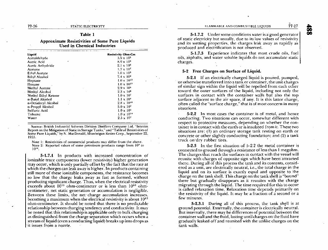
Table 1
Approximate Resistivities of Some Pure Liquids Used in Chemical Industries
Liquid Resistivity Ohm-Cm Ace ta ldehyde 5.9 x 10 5 Acetic Acid 8.9 x 10 8 Acetic A n h y d r i d e 2.1 x 10 6 Ace tone 1.7 x 10 7 Ethyl Aceta te 1.0 x 10 9 Ethyl Alcohol 7.4 x 10 H H e p t a n e 1.0 x 10¹³ H e x a n e 1.0 x 10! 8 Methyl Acetate 2.9 x 10 5
• Methyl Alcohol 2.3 x 10 6 Methyl Ethyl Ke tone 1.0 x 10 7 n-Butyl Alcohol 1.1 x 10 x n-Octadecyl Alcohol 2.8 x 10 l° n-Propyl Alcohol 5.0 x 10 7 Sulfur ic Acid !.0 x 10 2 T o l u e n e 1.0 x 10 TM
Wate r 2.5 x 10 7
Source: British Indus t r ia l Solvents Division Distillers C o m p a n y Ltd. " In t e r im Repor t on the Mitigation o f Static in Storage T anks , " and "Table o f Resistivities o f Some Pure Liquids," by N. MacDonald , Shawin igan Resins Corp. , Sep t ember 22, 1955.
Note 1 : Resistivities o f commerc ia l p roduc t s may d i f f e r . f r o m the above. Note 2: Repor t ed values o f s o m e p e t r o l e u m p roduc t s r ange f rom 10" to 1016"
5-1.7.1. In products with increased concentration of ionizable trace components (lower resistivity) higher generation may occur, which is only partially offset by the fact that the rate at which the charges can leak away is higher. In products containing still more of these ionizable components, the resistance becomes so low that the charge leaks away as fast as formed, without producing significant charge. Thus, when the electrical resistivity exceeds about 1015 ohm-centimeter or is less than 101° ohm- centimeter, net static generation or accumulation is negligible. Between these limits, the net charge accumulation increases, becoming a maximum when the electrical resistivity is about 1013 ohm-centimeter. It should be noted that there is no predictable relationship between charging tendency and conductivity. It may be noted that this relationship is applicable only to bulk charging as distir~guished from the charge separation which occurs when a stream of liquid (even a conducting liquid) breaks up into drops as it issues from a nozzle.
5-1.7.2 Under some conditions water is agood generator of static electricity but usually, due to its low values of resistivity and its wetting properties, the charges leak away as rapidly as produced and electrification is not observed.
5-1.7.3 Experience indicates that most crude oils, fuel oils, agphalts, and water soluble liquids do not accumulate static charges.
5-2 Free Charges on Surface of Liquid.
5-2.1 If an electrically charged liquid is poui-ed, pumped, o r otherwise transferred into a tank or container, the unit charges of similar sign within the liquid will be repelled from each other toward the outer surfaces of the liquid, including not only l~he surfaces in contact with the container walls but also the top surface adjacent to the air space, if any. It is this latter charge, often called the "surface charge," that is of most concern in many situations.
5-2.2 In most cases the container is of metal, and hence conducting. Two situations can occur, somewhat different with respect to protective measures, depending on whether the con- tainer is in contact with the earth or is insulated from it. These two situations are: (1) an ordinary storage tank resting on earth or concrete or other slightly conducting foundation; and (2) a tank truck on 'dry rubber tires.
5-2.3 In the first situation of 5-2.2 the metal container is connected to ground through a resistance of less than 1 megohm. The charges that reach the surfaces in contact with the vessel will reunite with charges of opposite sign which have been' attracted there. During all of this process the tank and its contents, consid- ered as a unit, are electrically neutral, i.e., the total charge in the liquid and on its surface is exactly equal and opposite to the charge on the tank shell. This charge on the tank shell is "bound" there but graduaIly disappears as it reunites with the charge migrating through the liquid. The time required for this to occur is called relaxation time. Relaxation time depends primarily on the resistivity Of the liquid. It may be a fraction of a second or a few minutes.
5-2.3.1 Duringal l of this process, the tank shell is at ground potential. Externally, the container is electrically neutral. But internally, there may be differences of potential between the container wall and the fluid, lasting until charges on the fluid have graduall)~ leaked off and reunited with the unlike charges on the tank walls.

77-28 STATIC ELECTRICITY
5,2.3.2 If the potential difference between any part of the !!quid surface and the metal tank shell should become high c . u u g , to cause ~onization of the air, electrical breakdown may occur and a spark may jump to the shell. Such aspark across the liquid surface could be the cause of ignition where flammable vapor-air mixtures are present. However, a spark to the tank shell is less likely than a spark to a projection or to a conductive object lowered into the tank. No bonding or grounding of the tank or container can remove this internal surface charge.
5-2.4 In the second situation mentioned in 5-2.2, the tank shell is highly insulated from the ground. The charge in the liquid surface attracts an equal and opposite charg e to the inside of the container. This leaves a "free" charge on the Outside surface of the tank, of the same sign' as that in the liquid, and of the same magnitude. This charge can escape from the tank to the groun d in the form of a spark. In filling a tank truck through an open dome, it is this source of sparking which is suspected to have caused some fires; in this case the spark jumps from the edge of the fill opening to the fill pipe which is at ground potential. This hazard can be controlled by grounding the container before fillin~ starts or hv bondin~r tho fill nlno tn the tank I~" , ro , ,na i , , -
I the tank is used, the fill pipe mustbe electrically conductive, i.e., I'no insulated conductive sections. Usually any resistance path of [ less than 1 megohm will serve (see Figure 3).
5-2.5 T h e foregoing discusses the distribution of charges delivered into a container with a flowing stream. Further genera- tion or separation may occur within the containerin several ways tO produce a surfac e charge:
(a) Flow with splashing or spraying of the incoming stream, (b) Disturbance o f water bottom by the incoming stream, (c) Bubbling of air or gas through a liquid, or (d ) Jet o r propeller blending within the tank.
5-2.6 These ch~arges on the surface of a liquid cannot be • prevented by bonding or-grounding, but can be rendered harm-
less 'by inerting the vapor space, b~ displacing part of the oxygen With a suitable inert gas, or by increasing the concentration of flammable gas in the vapor space to above the, upper flammable limit with a gas, such as natural gas.
FLAMMABLE AND COMBUSTIBLE LIQUIDS 77-29
5-3 Storage Tanks.
5-3.1 Storage tanks are 0ftwo general types: those having a - vapor, space a n d those having substantially no vapor space. A
cone-roof tank is an example of the former, and a floating-roof tank is an example of the latter.
5-3.2 When cone-roof tanks; or other spaces which m a y contain flammable mixtures of vapor and air , are filled with static-accumulating liquids, one or more of the following protec- tive measures [(a) through (h)] may be used depending upon the characteristics of the liquid handled:
(a) Overshot splash filling should beprohibited,except for fammable l!quids which experience indicates do not cause static ignition, such as crude oils. (b) Inlet fill.pipe should discharge near the bottom of the tank and should be designed to reduce turbulence to a minimum. I n general, the inlet stream preferably should be directed horizontally to reduce agitation of water and sediment on the. tank bottofn. (c) Charge production increases with flow velocity; hence, it follows that the occurrence of a static ignition is less likely with low flow velocities. Insofar as practicable, the linear velocity of the liquid in the pipe entering the tank should be kept below 1 meter per second until the pipe inlet is well submerged. (d) Water should be kept out of the incoming stream, insofar as practicable, since the charge density, or charge per unit volume, may be increased by the presence of an immiscible liquid, such as water, in the flowing stream and by its settling out in the tank. (e) -The pumping of substantial amounts of entrained air or other gas into a tank having a vapor space should be avoided, since bubbling of a gas through the flamma- ble liquid in the tank may generate charges and release them at the free liqui d surface. (f) I f a tankcontains a flammable vapor-air mixture
"from previous use,- the tank may b e made safe from explosion by ventilation (50 percent or less of the lower flammable limit) before pumping in a high 'flash point static-generating liquid.

77-30 STATIC ELECTRICITY
(g) Care should be exercised to eliminate the chance o f any ungrounded conductive floatable object finding its way into the tank since it could release all of its charge instantaneously as it approached the shell or other grounded surface. (h) Gaging or sampling through a r o o f manway or other roof opening with conductive" objects should be avoided until after filling has been completed and the surface turbulence has subsided. Depending upon the characteristics of the liquids, the size of the tank and the rate of fill, a waiting period of 30 minutes or more may be required for surface charge to dissipate to a safe level. (Nonconductive materials can be used for gaging or sampling at any time.) 5-3.3 When flammable liquids are pumped into a floating-
roof tank, the protective measures noted above are applicable until the roof becomes buoyant, after which no special precau- tions are necessary.
5-3.4 Spark ignitions inside tanks cannot be controlled by external grounding connections (see 3-1 and 5-2.3).
5-3.5 An external spark ignition is unlikely unless the tank is deliberately insulated from earth so that the resistance to earth exceeds 106 ohms.
5-4 Closed Piping Systems. '
5-4.1 Flow through metallic piping generates static but experience has indicated closed piping systems present no static hazard.
5-4.2 Bonding is not needed around flexible metallic pip- ing or metallic swing joints even though lubricated, but a bond should be provided around joints in which'the only contact ing surfaces are made of nonmetallic insulating material.
5-4.3 In areas where flammable vapor-air mixtures may exist, electrically isolated sections of metallic piping should be bonded to the rest of the system (or grounded) to prevent external sparks which might produce ignition.
5-5 Rubber-tired Vehicles.
5-5.1 Vehicles equipped with pneumatic rubber tires some~ times accumulate a charge of static electricity. This occurs only when the tires are dry and hence good insulators.
FLAMMABLE AND COMBUSTIBLE LIQUIDS 77-31
5-5.1.1 Such charging can arise from two separate and unrelated processes - - rolling contact of tires on the pavement, or filling fuel and cargo tanks. These are best considered separately, although, since the vehicle is separated from the ground by its tires, the electrical resistance of the tire plays an important part in both cases.
5-5.1.2 Static from vehicle motion is generated at the point of separation of the tire from the pavement. It becomes significant only at high speed operation when tires and pavement are dry.
5-5.1.3 Drag chains(dragstraps) were originally thought of as a means of bleedingthe static charge back to the road as fast as generated. It is now known that a drag chain is ineffective for this purpose when the road is dry and it is of course not needed when the road is wet. Furthermore, drag chains areineffective as a means of control of static during loading, as discussed below. Their use should not be required.
5-5~2 During filling the fuel tank or cargo tank of automo- tive equipment with a product having static-generating ability a charge is carried into the tank and will produce a charge on the Vehicle. Whether or not this can produce a hazard depends on the amount of charge and other factors, as discussed below:
5-5.2.1 The total charge carried into a vehicle depends on the generating characteristics and the total quantity of the product delivered. The rate of generation is thus a function of rate of delivery, and for a system of any given dimensions is a function of linear velocity of flow in the pipe lines.
5-5.2.2 I fa vehicle were perfectly insulated from ground, the voltage produced for any given delivery would be determined by the capacitance of the vehicle. Since the tires are not perfect insulators, some leakage occurs which limits the peak voltage which the vehicle may acquire.
5-5.3 When loading tank trucks through open domes, ex- perience has demonstrated a sign iris=ant static hazard can be developed. When the vehicle tires are dry, a potential may de- velop between the vehicle and the grounded piping system, and a spark may jump between the edge of the tank opening and the fill pipel To avoid this possibility, a bond should be established between the loading piping and the cargo tank (see Figure 1 ). The bond connection should be made bef6re the dome is opened, and should not be removed until the dome is closed.
O

77-32 STATIC ELECTRICITY
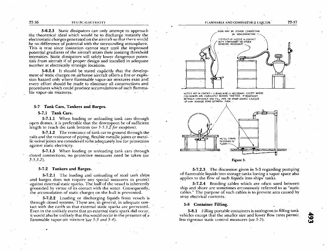
ALL PARTS OF FILL LINE SHOULD BE NN . ~ BOND ~IRE FASTENED ELECTRICAL . ~ TO FILL ~ ~ METAL CONTACT DOWN- ~ RACK ELECTRICALLY STREAM OF BOND .,~,_.~CONNECTED.~ TO RPING
f i ! ~ ~ I BATTERY CLIP OR / ', ] • \ 1]~ SPECIAL CONNECTOR•
./ ..... !,,. =.,. L \ I I ATTACH TO TANK I r - , , ~ ; ~ , , o - = FI \ II BEFORE OPENING
~l I - I f ' '" ALTER NATE Ju uu'"-'ll LOCATION
" ~ ~ - ~ - - / / / - - - / / / _ _
Figure i. Filling Tank Truck Through Open Dome.
CONDUCTING OR NO.-CO,DUCT,NG H;SE / f " ;
/ / - - - m ~
_ - _~- _--- -- - - _~.4.
Figure 2. F i l l ing or Emptying Tank Truck Through a Closed Connection.
FLAMMABLE AND COMBUSTIBLE LIQUIDS 77-33
5-5.3.1 The fixed end of the bond wire may be connected to the fill pipe, to any part Of a .metal loading rack which is e,ectrlcauy connected to me pipe, or to ground. It.is not necessary to bond around flexible metallic joints or swivel joints (unless of the insulating type) in the loading pipe. The attachment clip on the bond wire should be a battery clip or some other equivalent attachment so made that it can .pull free, thus avoiding inadver- tent damag e which might result from driving the vehicle away without" removing the bond.
• 5-5.3.2 Such bonding is not required: (1) when loading vehicles with products not having static-accumulating abilities, such as asphalt and crude oil; (2) where tank vehicles are used exclusively for transporting Class II or Class III liquids loaded at racks where no Class I liquids are handled; or, (3) where vehicles are loaded or unloaded through closed connections, so that there is no release of vapor a t a point where a spark could occur, irrespective of whether the hose o r 'p ipe used is conducting or nonconducting. A closed connection is one where contact is made before flow starts and is broken after flow is completed.
.~-.~'..~..$ ,qwitch ln~clincr i t u t P r m ,1~od tc~ r lP~cri l '~ ~ r~rrwl_
uct being loaded into a tank or compartment which previously held a product of different vapor pressure. Switch loading can result in an ignition when low vapor pressure products are.put into a cargo tank containing h flammable vapor from previous usage, i.e., furnace oil loaded into a tank which last carried gasoline.
5-5.3.4 ; During "switch loading" or when loading prod- ucts, excluding those enumerated in 5-5.3.2 above, which may give off vapors that are within the flammable range (see Graph 1 ), the fill pipe should reach as close as possible to the bottom of the tank being loaded, and preferably be in contact with the bottom. I f the fill pipe does not reach the tank bottom, the liquid velocity- in the fill pipe should be limited to approximately 3 feet per second until the outlet is submerged. I f the fill pipe reaches the bottom of the tank or aftei- the outlet of the fill pipe is covered~ the velocity may be increased to approximately 15-20 feet per second.
• 5-5.3.5 Where bottom loaciing is Used, low velocity or splash deflectors or other devices should be used to prevent upward spraying of the product and to minimize surface turbu- lence.
W} lilt

77-34 STATIC ELECTRICITY /
5-5.3.6 All metallic parts of the fill pipe assembly should form a continuous electrically conductive path downstream from the point of bonding. For example, insertion of a nonconductive hose equipped with a metal coupling on the outlet must be avoided unless the coupling is bonded to the fill pipe. This is not required in bottom loading.
5-5.3.7 Metal or condtictive objects, such as gage tapes, sample containers, and thermometers, should not be lowered into, or suspended in, a compartment while the compartment is being filled or immediately after cessation of pumping. A waiting period of approximately one minute will generally permit a substantial relaxation of the electrostatic charge. Nonconductive materials may be used anytime.
5-5.3.8 Care should be exercised to minimize the possi- bility of any unbonded object entering into a tank. Prior to loading, tanks should be inspected and any unbonde d object removed.
5"5.3.9 Filters capable of removing micron-sized parti- cles are considered prolific static generators. Therefore~ a minimum of 30-second relaxation time normally should be pro- vided downstream of the filter. This means that it should take at least 30 seconds for a particle of liquid to travel from the outlet of the filter element to the outlet of ' the fill pipe discharge into the tank truck compartment. Relaxation time may be obtained by enlarging or lengthening the pipeline, by installing a retention chamber, or by reducing the flow rate.
5-5.4 No external bond wire or bond wire integral with a hose is needed for the unloading of flammable liquids into underground tanks (see Figure 2).
5-6 Aircraft.
5-6.1 Fueling and Refuel ing o f Aircraft on the Ground. 5-6.1.1 When fueling aircraft, the aircraft should first be
bonded to the tank truck, drum, fueling cabinet, hydrant or pit, thus providing a low-resistance path to permit reuniting of sepa- rated charges; that is, so that charges delivered into the fuel tanks of the aircraft may reunite with charges left on the tank truck or other type of fueler.
5-6.1.2 When fueling is by over-the-wing delivery, the fuel nozzle should be connected to a metal part of the aircraft which is metallically connected to the fuel tank at a point near the
FLAMMABLE AND COMBUSTIBLE LIQUIDS 77-35
tank fill opening by means of a short bond wire and clip or plug. This connection should be made before the fill cap is removed and the nozzle is placed in the fill opening. It should not be detached until filling has been completed and the fill cap h'as been replaced.
5-6.1.3 When fueling is by underwing delivery, the fuel- ing is through a closed system. This closed system provides metal-to-metal contact and thus inherent bonding at the point of connection so that the bond connection ment ioned in 5-6.1.2 above is not required.
5-6.1.4 I f nonmetallic conductive hose is used, it shall not be regarded as a substitute for bonding.
5-6.1.5 When defueling aircraft, the static-protective measures shall be the same as those taken during fueling opera- tions.
5-6.1.6 Some regulations require, in addition to the bonding required in this section, that the aircraft and fueling system be connected by wires to ground. However, in many locations grounds are not available and evidence does not indicate that grounding is necessary for protection against static ignition.
5-6.2 Airborne Aircraft.
5-6.2.1 Bonding of aircraft parts to provide equalization of the potential between various metallic structures of the aircraft is desirable. While such bonding is common, portions of aircraft may be insulated, either because of imperfect bonding or because they are incapable of being electrically bonded (i.e., antenna lead-ins might be a source of static spark inside the aircraft structure when the antenna lead-in is connected to its receiver through a capacitor). Unbonded portions constitute a static fire hazard where flammable vapors are present and an explosion hazard where such flammable vapors exist within confined areas or structures of an aircraft.
5-6.2.2 High humidity conditions do not aid in the dissi- pation of static electrical charges on airborne aircraft as is oc- casioned on objects resting on the ground simply because of the absence of any continuous solid surface between the 'aircraft and the ground on which a moist film can be deposited. In fact, when humidity reaches the saturation point, an, increase in precipita- tion static results. Small traces of water vapor in a film on an insulator (as might be imparted by condensation) do, however, render the insulator conducting.
J
FLAMMABLE AND COMBUSTIBLE LIQUIDS 77-37 77-36 STATIC ELECTRICrFY
5-6.2.3 Static dissipators can only'at tempt to approach the theoretical ideal which would be to discharge instantly the electrostatic char~es ~enerated on the aircraft so that there wo,,h-1 be no d i f fe renceof l~otential with the surrounding atmosphere. This is true since ionization cannot start until the impressed potential gradients o f the aircraft attain their ionizing threshold intensities. Static dissipators will safely lower dangerous poten- tials .from aircraft if of proper design and installed in adequate number at electrically strategic locations.
5-6.2.4 It should be stated explicitly that the develop- ment of static charges on airborne aircraft offers a fire or explo- sion hazard only where flammable vapor-air mixtures exist and every effort should be made to eliminate all constructions and procedures which could produce accumulations of such flamm~i- ble Vapor-air mixtures. - ,
5-7 Tank cars, Tankers and Barges. 5-7.1 Tank Cars.
5-7.1.1 When loading or unloading tank cars through open domes, it is preferable that the downspout be of sufficient length to reach the tank bottom (see 5-5.3.2 for exception).
5-7.1.2 The resistance of tank car to ground through the rails and the resistance of piping, flexible metallic joints or metal- lic swivel joints are considered to be adequately low for protection against static electricity.
5-7.1.3 When loading or unloading tank cars through closed connections, no protective measures need be taken (see 5-5.3.2).
5-7.2 Tankers and Barges. 5-7.2.1 The loading and unloading of steel tank ships
a n d barges does not require any special measures to protect against external static sparks. The hull of the vessel is inherently grounded by virtue of its contact with the water. Consequently, the accumulation of static charges o n t h e hull is prevented.
5'-7.2.2 Loading or discharging liquids from vessels is through closed systems. These are, in general, in adequate con- tact with the earth so that external static sparks are prevented. Even in the unlikely event that an external static spark did occur, it would also be unlikely that this would occfir in the presence of a flammable vapor-air mixture '(see 5-3 and 5-4).
HOSE MAY BE EITHER CONDt, ICTING OR NONCONDUCTING
/ , NOZZLE NOT IN CONTACT- A BOND WIRE IS NECESSARY. EXCEPT WHERE CONTAINERS ARE INHERENTLY BONDED TOGETHER. IF RESISTANCE BETWEEN CONTAINER AND FILL PIPE OR OTHER SOURCE EXCEEDS IO o OHM. PROVIDE BOND BETWEEN THEM.,
/
Figure 3.
5-7.2.3 The discussion given in 5-3 regarding pumping of flammable liquids into storage tanks having a vapor space also applies to the flow of such liquids into ships' tanks.
5-7.2.4 Bonding cables which are often used between ship and shore are sometimes erroneously referred to as "static cables." The purpose of such cables is to prevent arcs caused by stray electrical currents~-
5-8 Container Filling. 5-8.1 Filling portable containers is analogous,to filling tank
vehicles except that the smaller size and lower flow rates permit less rigorous static control measures (see5-5). t ~

77-38 STATIC ELECTRICITY
5-8.2 Containers o f glass or other nonconducting materials are usually filled without special precaution.
5-8,3 Bonding is not required where a container is filled through a closed system.
5-8.4 In filling metal cans and drums, a fill spout, nozzle, or fill pipe, if conductive, should be kept continuously in contact with the edge of the fill opening. Conductive funnels, strainers, or other devices should likewise be kept in contact with both the fill nozzle and the container to avoid the possibility of a spark at the fill opening. Under these circumstances the additional precaution of providing a bond wire between the container and the fill connection is not warranted, except in special cases where the. container being filled is insulated so that the resistance between the container and the fill pipe exceeds l0 G ohms.
5-8.5 The need for extending a downspout to the bottom of ihe container has not been demonstrated by experience in filling containers up to and including 55-gallondrums.
5-8.6 When electrical contact cannot be maintained be- tween the fill pipe and the container, a bond wire should be used between them. Figure 3 illustrates various protective measures used in container filling.
5-9 Blending and Mixing Operations.
5-9.1 When mixers, churns, or autoclaves containing flammable liquids are being used, containers and filling lines
: should be bonded together, if not inherently bonded (see 5-8). However, this will not eliminate the free charge on the surface of the liquid (see 5-2).
5-9.2 Jet mixing and propeller mixing'in tanks may gener- ate charges. Care should be taken to avoid agitating a possible layer of water at the bottom of flammable liquid tanks. The jet or propeller stream should be directed so as not to break the surface. Jet mixing nozzles should not be used for filling tanks when the nozzles are above the liquid surface. Where flammable mixtures may be encountered above the liquid surface, inert gas blanketing may be employed. (See Standard on Explosion Preventio n Systems, NFPA No. 69.)
5-9.3 Floating-roof tanks eliminate the vapor space and, therefore, are especially desirable for hazardous blending ser- vice.
GASES 77-39
Chapter 6 Gases
6-1 General.
6-1.1 Gases not contaminated with solid or liquid particles have been found to generate little', if any, electrification in their flOW,
6-1.2 When the flowing gas is contaminated with metallic oxides or scale particles, etc., or with liquid particles or spray, electrification may result. A stream ol ~ such particle-containing gas directed against a conductive object will charge the latter unless the object is grounded or bonded to the discharge pipe.
6-1.3 When any gas is in a closed system of piping and equipment, the system need not be electrically conductive or electrically bonded, except that electrically isolated conductive sections should not be used.
6-2 Air Under Pressure. Compressed air containing parti- cles of condensed water vapor often manifests strong electrifica- tion when escaping.
6-3 Carbon Dioxide. Carbon dioxide, discharged as a liquid from orifices under high pressure (where it immediately changes to a gas and "snow"), can result in static accumulations on the discharge device and the receiving container. This condition is not unlike the effect from contaminated compressed air or from steam flow where the contact effects at the orifice play a part in the static accumulation.
6-4 Hydrogen-Air, Acetylene-Air Mixtures. Hydrogen- air and acetylene-air mixtures may be ignited by a spark energy of as little as 0.017 millijoule. In the pure state, no static charges are generated by the flow of hydrogen. However, as gaseous hydro- gen is commercially handled in industry, such as flowing through pipelines, discharging through valves at filling racks into pressure containers, or flowing out of containers through nozzles, the hydrogen may be found to contain particles of oxide carried off from the inside of pipes or containers. In this contaminated state, hydrogen gas may generate static.
77=40 STATIC ELECTRICITY
6-5 LP-Gases. 6-5.1 The liquefied petroleum gases (LP-Gases) behave in a
manner similar to that discussed in 6-1.1 •in the gas phase and 6-1,2-in the mixed phase.
6-5.2 Bonding is not required where vehicles are loaded or unloaded through closed connections, so that there is no release o f vapor at a point where a spark should occur, irrespe/ztive of whether the hose or pipe used is conducting Or nonconducting. A closed connection is one where contact is made before flow starts and is broken after flow has ended.
• I
DUSTS AND FIBERS 77-41
Chapter 7 Dusts and Fibers
7-1 " General. There are/-ec0rded instances where ignition of a dust cloud or layer is attributed tostatic electrical discharge. Production of static charge is commonly observed during han- dling and processing of dust in industry. That dust can be ignited by static dischai'ge has been verified experimentally by many investigators.
7-2 Parameters• Affecting Charge Generation. :7,2,1 A transfer of an electric charge occurs when two
materials in contact are separated. Dust dispersed from a surface may develop a considerable charge. The ultimate chargedepends on the inherent properties of the substance, size of particle, amount of surface contact, surface conductivity, gaseous break- down, external field and leakage resistance in a system. Greater charges develop from smooth than f rom rough suz:faces, proba- bly because of greater initial surface coritact. Electrification de- vczlops during the firstphase of separation. Subsequent impact o f airborne particles on obstructions may affect their charge slightly, but if the impact surface becomes coated with the dust, this effect • is slight.
7-2.2 Charge generation seldom occurs if both materials are g o o d electrical conductors; but it is likely to occur with a conductor and a nonconductor or two nonconductors. When like materials are separated, as in dispersing quartz dust from a quartz surface, positive and negative charges are developed in the dis- persed dust in about equal amounts to give a net zero charge. With materials differing in composition, a charge of one polarity may predominate in the dust. Each of the materials becomes equally charged but with opposite polarity. With a metallic and an insulating material, the former usually assumes positive and the latter a negative polarity.
7-2.3 Electrostaticcharge generation in moving dust nor- mally cannot be prevented. High humidity or grounding of the surface from which dust is dispersed will not eliminate the charge generation. T h e method of dispersion of the dust, the amount of" energy expended in dispersal, the degree of turbulende, and the composition of the atmosphere usually do not affect the mag- nitude or distribution of the charges. t Jr
77-42 STATIC ELECTRICITY
7-3 Energy Available in Static Discharge. The voltage de- veloped by dispersion of dust from a surface is proportional tO the
~ uantity of dust dispersed and the maximum voltage developed epends on the leakage resistance in the system ahd corona or
spark discharge. 7-3.1 The energy (millijoules) in a static discharge is ex-
pressed as ½ CV 2 x 10 -9, where C is the capacitance (picofarads) and V is the potential difference (volts). The spark energy is dissipated in radiation, in ionization, and in the heating of the gas and dust. The electrostatic voltage thus encountered in industry may range from a few volts to several hundred thousand. Sparks from a fraction of an inch to 8 inches or more in length have been observed.
7-3.2 The capacitance of an object dependsupon its physi- cal dimensions, and its proximity to adjacent objects. Generally the capacitance of pieces of machinery is estimated to range from 100 to more than 1,000 picofarads. The capacitance of t hehuman body is approximately 200 picofarads. Thus for average condi- tions, assuming 10,000 volts, the energy in a static spark discharge from a large insulated machine may be about 50 millijoules and that from a person 10 millijoules.
7-4 Ignition of Dust by Static Discharge.
7-4.1 Dust clouds and layers of many combustible materials (with or without a volatile constituent) have been ignited experi- menially by static discharge. In some instances, the charge was generated by movement of dust, in others by a static generator (Wimshurst machine), or by electronic equipment.
7-4.1.1 With dust clouds, it has been shown that a minimum dtlst concentration exists below which ignition cannot take place regardless of the energy of the spark. At-the minimum dust concentration a relatively high energy is required for igni- tion. At higher dust concentrations (5 to 10 times the minimum)i the energy required for ignition is at a minimum.
7-4.1.2 The circuit resistance required for optimum ig- niting power varies with the capacitance, the voltage, and the type of dust; it often ranges from-. 10,000 to 100,00(J ohms. In tfiis connection, it should be noted that metallic dust layers are usually poor electrical conductors unless compressed.
.7-4.2 A layer of combustible dust can be ignited by static discharge and will burn with a bright flash, glow, or, for some
• metallic dusts, with flame. Apparently, ther e is little correlation in
DUSTS AND FIBERS 77-43
the minimum energy required for ignition of dust layers and clouds. Layers of some metallic dusts such as aluminum, mag- nesium, titanium, and zirconium require less energy for ignition than carbonaceous materials.
7-4.3 Primary explosives, mercury fulminate and tetryl, for example, are readily detonated by static spark discharge. Steps necessary to prevent accidents from static electricity in explosive ] manufacturing operations and storage areas vary considerably] with the static sensitivity of the material being handled. ]
7-4.4 In all instances in which static electricity has been[ authentically established as the cause of ignition, the spark oc- ] curred between an insulated conductor and ground. It has n o t been verified experimentally that a dust cloud can be ignited by static discharge within itself.
7-4.5 T h e minimum elecffical energies required to ignite some dust clouds and layers are listed in Table 2. Note that many dusts can ignite with less energy than might be expended by a static discharge from machinery or from a human body.
7-5 Mixing and Blending Operatioffs.
7-5.1 Mixing, grinding, screening, or blending operations with solid nonconductive materials can generate static electricity. The degree of static hazard is influenced by the capacity to generate and accumulate a charge of sufficient potential to dis- charge a static spark capable of igniting any ignitible mixture which may be present in the path of the spark discharge.
7-5.2 One of the more common methods employed to drain off static is to bond and ground all metal parts and all moving parts of the equipment. Consequently, metal and other conductive material should be used as far as possible in design of components which are contacted by the solid material being processed, although this may not prevent the static charge on the dispersed dust.
7-6 Cotton Gins. 7-6.1 Experience has shown that the amount of energy
released by sparks due to static accumulations has not been of sufficient magnitude to ignite loose lint, dust or the cotton.
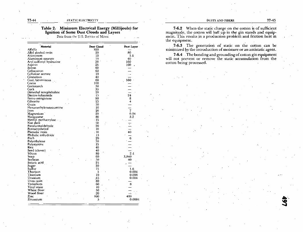
77-44 STATIC ELECTRICITY
T a b l e 2. M i n i m u m E l e c t r i c a l E n e r g y ( M i l l i j 0 u l e ) f o r
I g n i t i o n o f S o m e D u s t C l o u d s a n d L a y e r s = Data from the '.d.S. Barea-a 0fMin~~' ._
"Material Alfalfa Allyl alcohol resin Aluminum Aluminum stearate Aryl sulfonyl hydrazine Aspirin Boron Cellucotton Cellulose acetate
_ Cinnamon Coal, bituminous Cocoa " " Cornstarch Cork Dimethyl terephthalate Dinitro toluamide Ferro-manganese Gilsonite Grain Hexamethylenetetramine Iron Magnesium Manganese Methyl methacrylate , Nut shell Paraformaldehyde Pentaerythritol Phenolic resin Phthalic anhydride Pitch Polyethylene Polystyrene Rice Seed (clover). Silicon Soap Soybean Stearic acid Sugar Suffur Thorium Titanium Uranium Urea resin Vanadium Vinyl resin Wheat flour Wood flour .Zinc , Zirconium
Dust Cloud 320
20 10 10 2 0 25 60 60 10 40 60
100 30 35 20 15 80 25 30 10 20 20 " 80
r 15 50 20 10
-10 15 20 30 15 40 40 80 60 50 25 30 1'5 5 '
10 .45 80 60 . 10 50 -20 100
5
Dust Layer
80 1.6
40 160 160
560
24 8 4
7 0,24 3.2
% ' 7 -
4O
6
' . . . 2 -
2.4 3,840
4O
1.6 0.004 0.008 0.004
8
4OO 0.0004
DUSTS AND FIBERS 77-45
7-6.2 W h e n - t h e static c h a r g e o n the co t ton is o f suf f ic ien t m a g n i t u d e , the co t ton will ball u p i n the g in s t ands a n d equ ip -
. . . . • 7 r ~ 1 • i , • , , ,era. • ms resmts m a p r o d u c t i o n p r o b l e m a n d f r i c t ion n e a t in the e q u i p m e n t .
7-6.3 The generation of static on the cotton can be minimized by the introduction of moisture or an antistatic agent.
7-6.4 . T h e b o n d i n g a n d g r o u n d i n g o f co t ton g in e q u i p m e n t will n o t p r e v e n t o r r e m o v e the static a c c u m u l a t i o n t r o m the cot ton b e i n g processed .
4--

77-46 STATIC ELECTRICITY
Chapter 8 Industrial and Commercial Processes and Equipment
8-1 Coating, Spreading, and Impregnating.
" 8-1.1 " Coating, spreading, and impregnating operations are quite similar to each other in that they each involve the applica- tion of solut ionssuch as paints, lacquers, rubber compounds, "dopes," and varnish to fabrics, paper, or other materials. Vari- ous methods of applying the coating or impregnating material are employed. These include a doctor blade or knife, flowing roll, squeeze rolls, or calendar rolls and the method used is deter- mined by the viscosity and temperature of the coating or~impreg- nating solution, the speed of the machine, the thickness of the coating desired or the depth of the impregnation.
8-1.2 In each of these operations the material to be pro- cessed usually is unwound from a roll at the feed end of the machine, it passes over a series of rollers under a spreader or doctor knife where the coating material is applied, or through an impregnating tank between squeeze rolls and then under a doctor kniie, then over a steam table or through a drying oven, and is finally wound up on a reel or laminatedon skids. Static charges are often produced in each of these operations.
8-1.3 Where flammable liquids are employed in the pro- cess, definite precautions must be taken against possible ignition of flammable vapor-air mixtures. Static eliminators or neutraliz- ers should be installed where the rolls of materials are unwound or where they pass over rolls or under spreader knives or doctor blades. (For bonding of rotating parts, see 8-2.) .The frame of the machine should be permanently grounded by a substantial metal conductor that cannot be easily broken or removed.
8-1.4 Where flammable liquids are employed, adequate forced ventilation for the area and the equipment is o f primary importance and if humidification is not injurious to the process, as it is in some instances, the maintenance of relative humidity of 60 percent or more will be most helpful in the mitigation of static accumulations. In those areas where high relative humidity can be maintained and adequate forced ventilation is provided, static eliminators may not be needed. The ventilating fans should also be interlocked with the processing equipment so that they will be in operation before the process can be started (see 3-2).
INDUSTRIAL AND COMMERCIAL PROCESSES 77-47
8-1.5 Local htimidification and the installation of steam jets at the feed end of the machine and at other points of static generation have been found in some cases to be a practical means of static control.
8-1.6 Solvent containers such as hoppers should be en- closed and preferably filled through closed piping systems.
8-2 Transmission Machinery.
8-2.1 General. Some types of power transmission machine- ry frequently exhibit static generation, which may or may not warrant corrective measures depending on circumstances:
8-2.2 Flat Belts. 8-2.2.1 Rubber or leather flat belts running at moderate
or high speeds may generate sufficient static electricity to produce sparks several inches long. Such belts are usually .dry and good insulators because friction causes them to o p e r a t e a t tempera- tures higher than the surrounding atmosphere. Generation oc- curs where the belt leaves the pulley, as a result of the separation, and may.occur with either conducting or nonconducting pulleys. ~
8-2.2.2 Static generation can, be prevented by making the belt conducting by applying some special type of belt dressing. Such coatings must be renewed frequently to be considered practical or reliable.
8-2.2.3 A grounded metal "comb" with sharp points, placed with the points close to the inside of the belt and a few inches awa); from the point where it leaves the pulley, will be effective in draining off most of the static (see also 3-3). Such devices may sustain mechanical damage, and are seldom used on power equipment, although this same principle is electrically equivalent to the "tinsel bars" which are often tised on paper handling machinery (see 8-4.4).
8-2.3 Vee Belts. 8-2.3.1 Vee belts are not as susceptible to hazardous static
generation as flat belts. Fires attributable to Vee belt drives have usually resulted from the belt becoming overheated due to ne- glect, overloading or stalling.
8-2.3.2 While it has been suggested that Vee belt drives be avoided in areas where flammable vapors might be present, it is generally considered that the risk from the standpoint of static is small.

CONTAINER FOR COATING MATERIAL
H O P P E R T I C E L I M I N A T O R S ,
G R O U N DE D ~ ' q ~ " , ~ - - , , ~ ' ~ ' ~ . . . - - -CLOTH-- - , , . TO METAL, (o~. .~ 1(_) I I O ~ • Q (J E) L.) E) 0 ~ (3 ~ 0 FRAME , AJ[ _ , ' L - - R O L L S
- WIRE T O ~ , ~ GROUND
(~ . ~'----FLOOR LINE SPRINKLER PIPE OR OTHER
• CONVENIENT GROUND /
Figure 4. Gs~ounding of Cloth Coating Machine (Metal Frame) Showing Location of Static Eliminators.
S T A T I C E L I M I N A T O R S
1 • ~4 - - - - N O . 4 GTRANDEO COPPER WIRE
I TINCEL OAR
NOT(- CAR MAT BE HUNG ON GROUNDED WIRES OR RIGIDLY 8UPPORTE()o
A
~ ~ / ~ _~ / / . -~GROUN~D IDLER ROLL
; / , ' \ ~'. - NOT O,ER, ,NO.. J ; O . \~,,OT DLOSEN T~ , a ,NC.
CORRECT LOCATION OF STATIC COLLECTOR (T~NG(L RAN)
B
O
OR,, ,OLLE\ ~ " /p--T,NGEL ,,;,ox.J~ ,N.
° . . . . . E D . . . . . . . T E - . . - - - . , ~
t-
C Figure 5.
. , . .~-.~'-- GROUNDED IDLER ROLLS
GRAVURE PRINTING ROLt.R
D ,
Static Removal from Nonconducting Materials.
C
Z
8 g
-,4
~D
66P

77-50 STATIC ELECTRICITY
J 4~to6"[
Figure 6. P roper Location of Static Collector.
8-2.4 Conveyor Belts. 8-2.4.1 Belts used for the transportation of solid material
usually move at low velocity, and normally would not be static generators. However, if the materials transported are heated or are very dry, or if the belt operates in a heated atmosphere or moves with high velocity, generation might be significant.
Figure 7. Typical Ground Clamp for Solvent Containers. For Large Containers For Small Containers
~ " wing bolt 24 thds..pcqr ' inch. 5/~- headless n,,~- wing holt 28 thds. per inch. ~" headless conical point set K r e w 24 thds. per inch. #4 conical point set screw 28 thds. per inch. # 6 f lexible copper wire. flexible copper wire:
A B C" D E F G A B C D E F G Ye" 2- ~" 2¼" ~{D" 2" I" i~, il/{z h i~- I ~ " 5/~- I ~ " ~"
INDUSTRIAL AND COMMERCIAL PROCESSES 77-51
8-2.4.2 Materials spilled from the end of a conveyor belt into a hopper or chute may carry a static charge. If such charges cause difficulty, the belt support and terminal,pulleys should be electrically bonded to the hopper.
8-2.5 Pulleys and Shafting. 8-2.5.1 Metal pulleys will pick up a charge equal and
opposite to that carried by a belt which runs over them, and will communicate this charge to the supporting shaft, and thence through bearings to the equipment frame and the earth. Gener- ally, machinery frames are sufficiently conductive so that there can be no isolated metal parts capable of holding a static charge. In special cases involving such conditions as wood supports made dry by nearby heat sources, it may be necessary to electri~zally bond together and ground certain portions of the equipment.
8-2.5.2 While either ball or journal bearings are sufficiently conductive to carry off static charges from shafting and other rotating equipment, it has sometimes been found that the flow of static electricity across the oil film has resulted in roughening or pitting of bearing surfaces sufficient to adversely affect bearing life. Where experience indicates that such condi- tions are likely, it is customary to bond the shaft to the journal housing with some form o f sliding metal or carbon brush, to afford a low resistance path between the shaft and the housing. Where a bearing incorporates a nylon or other nonconductive bearing material, the shaft should be bonded as described above.
8-3 Dry Cleaning. 8-3.1 The dry cleaning process consists of removing dirt,
grease, and other stains from wearing apparel, textiles, fabrics, and rugs by the use of nonaqueous liquid solvents, flammable or nonflammable.
8-3.2 For the purpose of static electricity hazards, consid- eration need only be given to Class II and Class III plants since Class I plants are now prohibited and Class IV utilize solvents classified as nonflammable. For classification of dry cleaning plants, see the Standard/or Dry Cleaning Plant~, NFPA No. 32.
8-3.3 Commercial dry cleaning operations are in closed machines except for spotting operations. The operations em- ployed - - immersing fabrics, some of them highly insulating, in various solvents which are themselves good insulators and good
OI O O

77-52 STATIC ELECTRICITY
generators of static electricity, stirring and agitating them, and removing them from the solvent bath - - are all likely to produce OLOLt . tL v,--llg.tl (I~i,..0 L I l l t l t l t ~ I l I * ~ U I I O L I I I ~ 3 U l I d L C ~ , t . ) l L / t i C I I I d L [ I l g l l 8 l l l Y I J l V ~ L l .
These handling operations are also true of home dry cleaning. . Where such charges reach conducting parts of equipment, they
may be removed or neutralized by bonding or grounding. 8-3.4 Storage tanks, treatment tanks, purifiers, pumps, pip-
ing, washers, extractors, drying tumblers, and drying cabinets, if not inherently electrically conductive should be bonded. This system of equipment will be grounded because of the electrical power services installed thereon. In those situations where there are isolated units of equipment, such as drying cabinets, they should be grounded.
8-3.5 Metal tops of spotting tables should be permanently and effectively g rounded .
8-3.6 The accumulation of static electricty on pulleys and belting as used in dry cleaning rooms can be mitigated by the in- stallation of properly grounded combs, collectors, or neutralizers.
8-3.7 It should be noted that a free charge may exist on the surface o f the solvent when in equipment such as washers or
. . . . . . . . . . / . . . ¢ o w - . . CPuirges o n Slz'(face e/ i~tqu, tu). i l letetoie, e A i l l l 3 i ~ . L t a l l 3 ~-JlSg J - - , ~ , i ' # [S l~ "*¢~ ¥ 2 - - . . ' 2 J " 1 e l ~ L - - C - - .
special consideration should be given to the generation and accumulation of static electricity in the handling of the fabrics. Where fabrics are transferred from one piece of equipment to another, the two pieces of equipment should be electrically bonded together.
8-3.8 Humidification can be employed in dry cleaning op- erations to assist in the dissipation of static electricity (see 3 - 2 , H u m i d i f i c a t i o n ) .
8-3.9 Personnel performing d r y cleaning operations can accumulate a static charge. Control of such static is discussed in 2-4, Personnel Electrification.
8-4 Printing and Lithographing. 8-4.1 General.
" 8-4.1.1 In the printing and lithographing industries stat- ic electricity is a frequent, annoying, and often expensive source of trouble from the production standpoint. Where flammable inks and solvents areused in the process, static may create a fire or explosion hazard.
INDUSTRIAL AND COMMERCIAL PROCESSES 77-53
8-4.1.2 In practice, sheets charged with static electricity have an attraction for other objects which often, caoases, difficulty~, _" . . . . . . . . l a" , i I , - I 111 I 5 O l l t l O l l l l l i ~ t i l e S I I e e L S o r w e d s a n t i s o m e u m e s teanng o r m e
webs. It may also cause an increase in offset due to more intimate contact of the surfaces of the sheet in the delivery pile or from the attraction of the ink to the underside of the overlying sheets. The printed image may al~o be damaged by the attraction of dust particlesand loose paper fibers to th e paper.
8-4.1.3 The static discharge may also result in injury to people associated with the process. The discharl~e in itself is not dangerous to humans, but it may cause an involuntary reaction which results in a fall or entanglement with moving machinery.
8-4.2 Paper. 8-4.2A ' The character of the paper surface has a great
deal to do with the amount of static generated, the rougher- surfaced papers generating more than the smooth, calendared type. This, however, is somewhat offset by the fact that the calendaring operation itself is a source of static generation which, added to the static generated by the paper passing through the air, often results in a highly polished calendared paper having a higher charge than the rougher-surfaced paper.
8-4.2.2 The hygroscopic quality of the paper is also de- termined to some extent by the character Of the surface of the paper, which likewise has a distinct bearing on the generation of static by the paper. The more water content in the paper the less will be the amount of static generated. The difficulties in process- ing cellulose acetate sheets which are moistureproof is an excel- lent example in support of this statement.
8-4.2.3 If all paper used in the paper industry were in equilibrium with the air at a relative humidity of 40 percent or more, there would probably be little need for other means of static control. However, in the attempt to reduce the generatiori of static by increasing the moisture content, other production problems are sometimes introduced because paper will change in dimension and flexibility with changes in moisture and registra- tion defects may result. The ink drying rates may ~/lso be affected.
8-4.3 Inks. Ordinary inks used i n the printing industry t~l contain only slightly volatile solvents and-present little f i re or explosion hazard. High-speed printing requires the use of fast- I i

77-54 STATIC ELECTRICITY
drying inks necessitating the use 'of flammable solvents, such as naphtha, xylol, toluol, or ethyl alcohol. This introducesa serious fire and explosion hazard due to the possibility of ignition o f flammable vapor mixtures by static sparks, in addition to other ignition sources.
8.4.4 Presses. 8-4.4.1 A great deal of static is generated by the paper
running through the press, when it is pulled from a roll or stack, when it touches the roll or feeder device which carries it to the
~ rinting surface, during the actual impression, or in any of the andling equipment provided between the impression and the
final delivery roll or stack. 8-4.4.2 The most common method of removing static
electricity from presses is by grounding, although grounding the framework in itself is frequently not sufficient protection against static. Static collectors or neutralizers are commonly used in close proximity to the paper as described under 3-3. However, the elimination of static at.' any one point in the printing operation does not prevent the generation of static in the later steps of the
rOCeSS and static neutralizers may be necessary at a number of cations. Draining the charge from one side of a web of paper
does not alwayg dra!n the charge from the opposite side. 8-4;4.3 When tinsel bars are used it is necessary to re-
place tinsel when it is damaged or, on presses using a paraffin spray, when it becomes coated with wax. Static collectors are frequently attached to thef ly to assist in removing static from the delivered sheets.
8-4.4.4 Humidification is one of the most successful methods of controlling static electricity (see 3-2). The amount of moisture required and the method of introducing it in the air differs somewhat with the paper being run and local pressroom conditions. Usually a range from 45 percent to 60 percent relative humidity is most practical. In plants with ventilating systems humidification is comparatively simple and, in others, moisture is introduced most easily by means of escaping steam.
8-4.4.5 In addition to the above methods of controlling static, a very common device used on presses is the open gas flame. This, of course, can only be used in presses using inks of low volatility. In some cases electric strip heaters are used instead of the open gas flame. The heater or open flame is placed across the press at the delivery end so as to allow the paper to pass through the flame quickly or very close to the heater. In every case where a gas flame is used for static elimination, the bm:ner should
/ /'INDUSTRIAL AND COMMERCIAL PROCESSES 77-55
be interlocked with the press so that the flame will be out when the press is stopped. It is necessary to make sure that the pilot of the burner cannot touch the edge of the paper.
8-4.4.6 The electric neutralizer is used frequently for the elimination of static on all presses, but fiaore particularly on rotary-type presses'(see 3-3,7onization). Ink spray from the ends of the rolls tends to accumulate on the ends of the neutralizers and it is important that theybe kept reasonably clean at all times because
h e a v y ink deposits have caused electrical breakdowns of the neutralizers in a few cases.
8-4.4.7 Higher operating speeds have resulted in the development of the enclosed ink fountain which makes for a much safer press. The elimination of the flammable vapors by proper local ventilation is probably the best solution to eliminat- ing fires o n t h e s e presses. Conditioned air is conducted to the .presses a n d exhausted from the paper as it passes from the
~ rinting cylinder. This not only assists in the rapid drying, but eeps the vapors below the lower flammable limits.
8-4.4.8 From the fire standpoint presses of slow speeds do not present the static problem exhibited in high-speed presses. Inks used on flat-bed presses are nearly always of low volatility.
'However , the static electricity problem from the production standpoint still exists. This type of press, using individual sheet
pape r , is used for mtilticolor work when it is frequently necessary to run work through two or more presses. The problem of exact register as well as a satisfactory delivery of the individual sheets from the fly is affected by static build-up in the printing. Even releasing the sheet from the tympan is sometimes difficult. One of the most satisfactory treatments for adhesions to the tympan is the use of glycerine.and acetic acid to dampen it.
8-4.4.9 A rotogravure press is an ideal static generator. A rubber r011 is pressed with as much as four tons of pressure against a copper etched roll, which re,~olves in a heavy volatile'ink, and the paper passes .between the two rolls. In a multicolored press there is a similar arrangement for each color. At high speeds the presses will often develop static charges of sufficient intensity to ignite flammable vapors over the ink" fountains or in the vicinity, if adequate ventilation is not provided. The generation of static can sometimes be reduced by reducing the pressure be- tween the rolls and changing the angle at which the paper enters the rolls to lighten its contact with each roll. For more complete control, however, a static collector or neutralizer, covering the full width of the web at the delivery side o f each impression roller, is usually necessary.
O
77-56 STATIC ELECTRICITY
8-5 Spray Finishing.
8-5.1 While the application o f paint, varnishes, enamels, lacquers, and other finishes by the spray method may generate small charges of static electricity, actual experience indicates that the hazard is not at all acute with the exceptio n of the airless spray ~ finishing operations.
8-5.2 Since high fluid pressures are used wkh "airless" spray finishing equipment, static can accumulate on the object being sprayed and on the spray gun. If a flammable liquid is involved, as it generally will be, a potentially hazardous situation exists. Therefore, any conductive object being sprayed should be bonded to the."airless" equipment or the two pieces of equipment should be grounded.
8-6 Steam Jets. I 8-6.1 w e t steam escaping into the atmosphere can generate I static electricity. Surfaces on which steam condenses may accumu- [ latestaticunless the surfaces are bonded to the discharging pipe [or both units are grounded. A resistance between connecting [parts of 10 6" ohms or less should be adequate. If flammable
vapor-air m~xtures are likely to be present, steam jets should be avoided. Also, when a steam eductor is used to venulate a tank containing a flammable vapor, the eductor should be used so that it will pull the vapor out of the tank (not blow steam into the tank) and it should be electrically bonded to the tank.
8-6.2 When steam cleaning constitutes a hazarcl, all pipes or • nozzles through which steam is discharged should be bonded to
the equipment being steamed or the two objects should be con- nected to ground.
STATIC DETECTORS 77-57
Chapter 9 Static Detectors
9-r Electrometer Amplifiers.
9-1.1 Electrometer ami~lifiers are frequently used for labo- ratory and field investigations of static electricity. These am- plifiers employ special input stages giving high input resistance and consequent low current drain; such amplifiers may employ vacuum tubes, or solid state devices or combinatiom of both. In the voltmeter configuration, typical input resistances are 1014 or more ohms and typical voltage sensitivity is O.1 to 1.0 volt full scale. Addition of resistive terminal shunts converts the volt- meters to current meters. The manufacturer's literature usually describes additional, simple adaptations toconvert the Voltmeters into megohm meters.
9-1.2 The typical electrometer voltmeter-amplifier has a frequency response extending from d.c. (zero hertz) to a few hundred hertz. In many circumstances the external circuit, from which the measurements are derived, has a frequency response which is even more limited than that of the electrometer'unit. The manufacturer's specifications and recommendatior/s must be studied carefully before the user attempts quantitative measure- ment of transient voltages and charges.
9-1.3 With a small "antenna" mounted on the input termi- nal, electrometer amplifiers can demonstrate transient electro- static charge effects within the limifations discussed in 9-1.2 above. In the presence of a constant electric field the charge previously induced at the input terminal will leak off and the meter pointer will return to zero. However, the rate of leakage is not high and the electrometer voltmeter may be used for "on the spot" qualitative indications under many diverse circumstances. ' 9-1.4 The constant field.limitation of 9-1.3 may be avoided by use-of a commutating enclosure which alternatively exposes the "antenna" to the external field and to a field-free region. With this adaptation the units are called Field Strength Meters (or Field-mills or Generating Voltmeters, etc.). Field Strength Meter calibrations usually are given in terms of a charged, flat metal plate separated from the sensing element by a charge-free region. Where. a volume distribution of electric charge is present, other calibrations are required. •
9-1.5 Instrument packages'°r subassemblie~s are available Which employ sophistication beyond that of the simple electrome- ter voltmeter or amplifier described above. Such instruments are

77-58 STATIC ELECTRICITY
usually quite expensive; presumably their usage would be only by experienced practitioners.
9-2 Electrostatic Voltmeters. These meters operate by elec: trostatic attraction between moveable and stationary metal vanes. No current is passed to maintain deflection because one set of vanes (usually the stationary one) is very highly insulated. Small, portable, accurately calibrated instruments are available in sev- eral ranges from 100 to 5,000 volts. This type of meter may be used for quantitative electrostatic analysis.
They are priced about the same as any high-quality meter, and are fairly rugged. Regrettably, these instruments are becoming difficult to purchase.
9-3 Leaf Deflection Electroscopes. The leaf deflection elec- troscope is a simple and sensitive device demonstrating the pres- ence or absence of electrical charge through the mechanism of repulsion of objects charged with like sign charges. Only units intended as portable dosimeters for ionizing radiation and one or two classroom demonstration models are available.
9-4 Neon Lamps. A small neon lamp or fluorescent tube will light up feebly when one terminal is grounded (or held in the hand) and the other makes *contact with any sizeable conductor that carries a charge potential of 100 volts or more. Like the electroscope, it gives but little quantitative information; however, inasmuch as it passes current it may give a rough idea of the rate at which charges are being produced in certain operations. Adjust- able series-parallel gT. oupings of such lamps and small.capacitors can be arranged to gwe a semblance of quantitative information.
9-5 Caution. Battery or line-power operated instruments must be judiciously handled in hazardous areas. It must be remembered that the primary object of all these investigations is to eliminate the possibility of sparks; arcs, and other ignition sources. Therefo~re, the use of battery or line-powered instru- ments should only be undertaken with extreme care to avoid ignition sources caused by the instrument or from' defects of faulty techniques. Test probes placed in ducts or regions contain- ing explosive vapors or dust clouds should be highly .insulated where they enter, and be made of materials haying a resistivity of over 104 ohm-centimeter in order to avoid condensed sparks to or from the probe itself; such resistance will not affect the readings appreciably.
APPENDIX A 77-59
Appendix A Glossary of Terms
Words or terms found in the dictionary are not defined here. The following technical words have been defined here in terms of their usage in the field of static and their usage in this manual. Therefore, the definitions are not necessarily of a general or complete nature.
Capacitance. Measured in farads or fractions thereof: capaci- tance is something like a tank of air. Each ounce of air puhaped into the tank raises the pressure in the tank a certain amount. This amount is determined by the size or capacity of the tank and the pressure of air already in the tank. In a tiny tank the pressure rise is large when a fixed amount of air is introduced. In- a lfirge tank the pressure rise is small when the same amount of air is added. Naturally the air will remain in the tank until someone opens the valve to let it out or until the tank bursts.
To say this same thing electrically, electrons (like the air above) i-eceived by an electric_ally neutral body of material (tank) such as a man, a car, an airplane, raise the voltage (pressure) at a rate depending upon the surface area and shape of the body. The voltage is determined by the surface characteristiCs (capacitance) of the body a n d the number of electrons on this surface. The larger the body the more electrons are needed to raise the voltage a specific amount. Hence the higher the capacitance of this body. Obviously a body that is large, like an aircraft, can receive and give up many electrons without a large change in voltage. Thus, it has a large capacitance. And likewise a small body like a pin head can spare or take on only a few electrons which will make large changes in voltage and hence it has a small capacitance. The main difference between the electrical charge and the air explanation is that with electricity the charge remams on the outside surface of the object while the air remains inside.
Capacitance is measured in terms of "farads." Actually, the farad is so tremendous a number that it is easier to talk about millionths of a farad or "microfarads," and millionths of
1/1,000,000 of a farad or "picofarads." " . 0
Charge. Measuredln coulombs or fracuons thereof: the static charge on a body is measured by the number of separated electrons on the body (negative charge), or the number of sepa- rated e l e c t r o n s no t on the body (positive charge). Electrons cannot be destroyed; so obviously when an electron is removed from one
OI
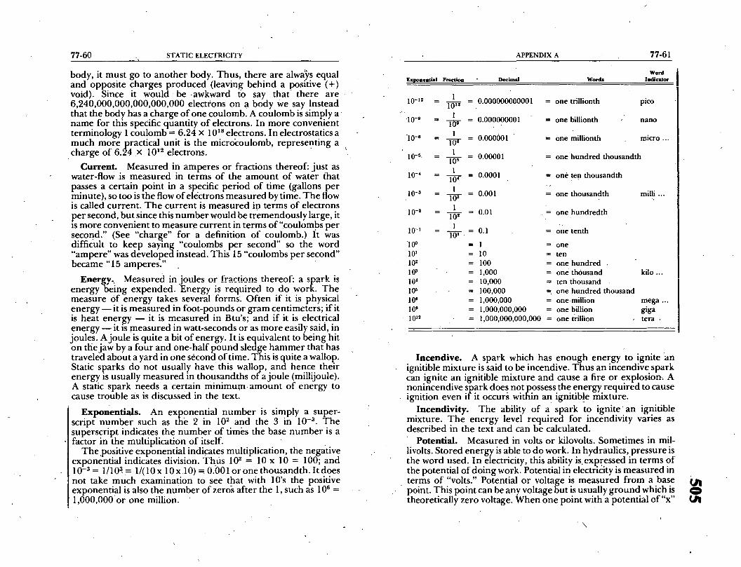
77-60 S T A T I C E L E C T R I C I T Y
body, it must go to another body. Thus, there are alw@s equal and opposite charges produced (leaving behind a positive (+) void). Since it would be .awkward to say that there are 6,240,000,000,000,000,0_00 electrons on a body We say instead that the body has a charge o f one coulomb. A coulomb is simply a name for this specific quantity o f electrons. In more convenient terminology 1 coulomb = 6.24 x 10 xs electrons. In electrostatics a much more practical unit is the micro~coulomb, represent ing a charge of 6.24 x 10¹² electrons.
Current. Measured in amperes or fractions thereof: just as water-flow is measured in terms of the amoun t o f water that passes a certain point in a specific period of time (gallons per minute), so too is the flow of electrons measured by time. The flow is called current . T h e current is measured in terms of electrons per second, but since this number would be t remendously large, it is more convenient to measure current in terms of "coulombs per second." (See "charge" for a definition of coulomb.) It was difficuh to keep saying "coulombs per second" so the word "ampere" was developed instead. This 15 "coulombs per second" became "15 amperes."
Energy. Measured in joules or fractions thereof: a spark is energy being expended. Energy is required to do work. The measure Of energy takes several forms. Often if it is physical energy - - it is measured in foot-pounds or gram centimeters; if it is heat energy - - it is measured in Btu's; and if it is electri'cal energy - - it is measured in watt-seconds or as more easily said, in joules. A joule is quite a bit o f energy. It is equivalent to being hit on the jaw by a four and one-half pound sledge h a mme r that has traveled about a yard in one second of time. This is quite a wallop. Static sparks do not usually h a v e this wallop, and hence their energy is usually measured in thousandths of a joule (millijoule). A static spark needs a certain m i n i m u m amoun t of energy to cause trouble as is discussed in the text.
Exponent ials . An exponential number is simply a super- script number such as the 2 in 102 and the 3 in 10 -3 . The superscript indicates the number of times the base number is a factor in the multiplication o f itself.
The .positive exponential indicates multiplication, the negative exponential indicates division. Thus 102 = 10 x 10 = 100; and 10 -a = 1/103= 1/(10x 10x l0 ) - 0.001 or one thousandth. It does not take much examination to see that with 10's the positive exponential is also the number of zero~ after the 1, such as 10 e = 1,000,000 or one million.
A P P E N D I X A 7 7 - 6 1
Word Exponential Fraction Decimal Words Indicator
1 0 - 1 2
"1 O- g
"10-e
lO-S.
10-4
10-a
10-2
1 0 - '
1 0 °
10 l
102
103
i04
105
10 e
109
10 TM
1 10 t2
1
109
1
106
1
10 ~
1
104
1
10 ~ 1
102
1
10 t .
- 0 . 0 0 0 0 0 0 0 0 0 0 0 l
- 0 . 0 0 0 0 0 0 0 0 1
- 0 . 0 0 0 0 0 1
- 0 . 0 0 0 0 1
- 0 . 0 0 0 1
- 0 . 0 0 1
0 .01
- 0 . 1
= 1
= 10
= 100
= 1 , 0 0 0
= 1 0 , 0 0 0
= 1 0 0 , 0 0 0
= 1 , 0 0 0 , 0 0 0
= 1 , 0 0 0 , 0 0 0 , 0 0 0
= o n e t r i l l i o n t h p i c o
= o n e b i l l i o n t h n a n o
-- o n e m i l l i o n t h m i c r o . . .
= o n e h u n d r e d t h o u s a n d t h
= o n e t e n t h o u s a n d t h
= o n e t h o u s a n d t h m i l l i . . .
= o n e h u n d r e d t h
= One t e n t h
= o n e
= t e n
= o n e h u n d r e d .
= o n e t h o u s a n d k i l o . . .
= t e n t h o u s a n d
-- o n e h u n d r e d t h o u s a n d
= o n e . m i l l i o n m e g a ...
-- o n e b i l l i o n g i g a
1 , 0 0 0 , 0 0 0 , 0 0 0 , 0 0 0 = o n e t r i l l i o n t e r n ,
Incendive. A spark which has enough energy to ignite an ignitible mixture is said to be incendive. Thus an incendive spark can ignite an ignitible mixture and cause a fire or explosion. A nonincendive s ark does, not ossess the..energy required to cause ignition even i?i t occurs within a n ignltlb!e mixture.
Ineendivi ty . The ability of a spark to ign i t e an ignitible mixture. The energy level required for incendivity varies as described in the text and can be calculated.
Potential . Measured in volts or kilovolts. Sometimes in mil- livolts. Stored energy is able to do work. In hydraulics, pressure is the word used. In electricity, this ability is.expressed in terms of the potential of doing work. Potential in electricity is measured in terms of "volts." Potential or voltage is measured f rom a base point. This point can be any voltage but is usually g round which is theoretically zero voltage. When one point with a potential o f " x "
\
O tall
77-62 STATIC ELECTRICITY
volts to ground is compared with another point with a potential of "y" volts to ground, then we say that a potential difference of"x-y" volts, exists between, the two points. Obviousl~y ,. then, when a point. with a potenual of 2500 (+) volts to g round is compared with a point with a potential of 1500 ( - ) volts to ground the potential difference is 4000 volts.
Resistance. Measured in ohms or megohms. Electrical cur- rent encounters difficulty in passing through an electrical circuit or conductor. This difficulty can be measured and is called resistance. In hydraulics, the resistance to water passing through a pipe is called friction loss and is measured in pounds lost in pressure over the length of the pipe. In electricity, resistance can be measured in terms of voltage drop over a part of the circuit but usually' is measured in terms of"ohms." The resistance of a circuit in ohms is equal to the ratio of voltage in volts to current in amperes" (i.e., ~ = 10ohms, ~ = 1 megohm).