NFPA 77 - National Fire Protection Association · PDF fileThe current NFPA 77 figure is...
14
NFPA 77 77-I- (5-1.7i: Accept SUBMITTER: D.M. Johnson, Standard Nil Co. of California RECOMMENPATINN: In the third and fourth sentences replace "1NlI~,, with "2 x IN12~" A similar change may he required in 5-1.7.1 to be consistent. SUBSTANTIATION:- For many years the American Petroleum Institute has published in its API-2OO3-Recommended Practice for Protection Against Ignitions Arising Out of Static, Lightning and Stray Currents that "except for mists, electrostatic accumulation is not significant when the conductivity of the liquid exceeds 50 picosiemens per metre." This applies to petroleum-derived vapors and gas~s that make up the vast majority of all flammable liquids. Accordino to my calculations, the resistivity of IN10 ohm-centimeters currently in NFPA77 is 200 times the equivalent conductivity successfully used by the petroleum industry for many years. The current NFPA77 figure is apparently much more conservative than has been demonstrated in test and in practice tb be needed for safe operation. COMMITTEE ACTION: Accept. See Action taken in a-1.7 of the Committee revision to NFPA77. 77- 2 - (Entire Standard): Accept SIBMITTER: Technical Committee on Static Electricity RECOMMENDATION: Revise and reorganize the 1977 edition of NPPA77 for editorial clarification. SUBSTANTIATIO~ For purposes of clarity, and for improved organization, the Committee proposes the revision of NFPA77. The rewritten document embodies changes that are editorial in nature. Some of the major changes in reorganization are outlined hereafter. Chapters i and 2 have been combined to a large degree under the heading "General." The new Chapter 2 is entitled "The Hazards of Static Electricity," and some process and personnel hazards are discussed briefly therein. Chapters 3 and 4.of the 1977 edition, which had been titled "Dissipation of Static Electricity and Control of Ignitible Mixtures," resoectively, have been broke~up. Someof the subjects in those chapters now appear in the new Chapter 3, and also in Chapter 4. Cha~ers 5, ~, and ~ of the 1977 edition have been altered somewhat e d i t o r i a l l y . Chapter 8 of the 1977 edition remains largely the same, but it will become rha~ter 7. There is a new section included on plastic drums. Chapter 9 is now Chapter 8, "Detection and Measurement of Static Accumulations." It has been rewritten and expanded, and has also been undated to current state of the art. The Appendix section is almost entirely the same. COMMITTEE ACTION: Accept~ Recommended Practice on Static Electricity NFPA 77 -- 1983 Chapter I . General i I-1 Purpose. 1-'1.1 The purpose of this recommended practice is to assist in reducing the fire hazard of static electricity by presenting a discussion of the nature and origin of static charges, the general methods of mitigation and recommendations in certain specific operations for its dissipation. I-1.2 Static electricit'y is often the ignition source for an ignitable mixture, an operating problem in industry or an annoyance to snme individuals. I-2 Scope. \ 1-2.1 This publication covers methods for the control of static electricity for the purpose of eliminating or mitigating its fire hazard, except as provided in 1-2.2 and I-2.3 below. 1-2.2 The prevention and control of static electricity in hospital operating rooms or in areas where flammable anesthetics are administered are not covered by this publication but are covered in NFPA56A, Standard for the Use of Inhalation Anesthetics. 1-2.3 Lightning is not covered by this publication but is covered in N~PA~, Lightnino Protection CoHe. NFPA 77 I-3 Definitions. (See also Appendix A.) Approved. Acceptable to the "authority having jurisdiction." NOTE: The National Fire Protection Association does not approve, inspect or certify any installations, procedures, equipment, or materials nor does i t approve or evaluate testing laboratories. In determining~he acceptability of installations or procedures, equipment or materials, the authority having jurisdiction may base acceptance on compliance with NFPA or other appropriate standards. In the absence of such standards, said authority may require evidence of proper installation, procedure or use. The authority having jurisdiction may also refer to the listings or labeling practices of'an organization concerned with product evaluations which is in a position to determine compliance with appropriate standards for the current production of listed items. " ~ Authority Having Jurisdiction. The "authority having jurisdiction" is the organization, office or individual responsible for "approving" equipment, an installation or a procedure. NOTE: The phrase "authority having jurisdiction" is used in NFPA documents in a broad manner since jurisdictions and "approval" agencies vary as do their responsibilities. Where public safety is primary, the "authority having jurisdiction" may be a federal, state, local or other regional department or individual such as a fire chief, fire marshal, chief of a fire prevention bureau, labor department, health department, building official, electrical inspector, or others, having statutory authority. For insurance purposes, an insurance inspection department, rating bureau, or other insurance company representative may be the "authority hiving jurisdiction." In many circumstances the property owner or his designated agent assumes the role of the "authority having jurisdiction"; at government installations, the commanding officer or departmental official may be the "authority having jurisdiction." Bonding. The process of connecting two or more conductive objects together by means of a conductor. Ignitable Mixture. A vapor-air, gas-air, dust-air mixture or combinations of. these mixtures which can be ignited by a static spark. Grounding (Earthing). THe process of connecting one or more conductive objects to the ground, and is a specific form of bonding. The words Bonded or Grounded, as they are used in the text, must be understood to mean either that a bond or ground as defined, has been deliberately applied, or that an electrically "conductive path having a resistance adequately low for the intended purpose (usually 106 ohms or less) is inherently present by the nature of the installation. Labeled. Equipment or materials to which has been attached a label, symbol or other identifying mark of an organization acceptable to the "authority having jurisdiction" and concerned with product evaluation, that maintains periodic inspection of production of labeled equipment or materials and by whose labeling the manufacturer indicates compliance with appropriate standards o~ performance in a specified manner. Listed. Equipment or materials included in a l i s t published by an organization acceptable to the "authority having jurisdiction" and concerned with product evaluation, that maintains periodic inspection of production of listed equipment or materials and whose listing states either that the equipment or material.meets appropriate standards or has been tested and found suitable for use in a specified manner. NOTE: The means for identifying listed equipment may vary for each organization concerned with product evaluation, some of which do not recognize equipment as listed unless i t is also labeled. The "authorlty hawng jurlsdlctlon" should~ut111ze the system employed by the listing organization to identify a listed product. Should, Indicates recommendations or that which is advi, sed but not required. StaticSpark. An impulsive discharge of electricity across a gap between two points not !n contact. I~4 Introduction. 1-4.1 The term "static electricity," as used in this publication, means electrification of materials through physical contact and separation, and the various effects that result from the positive and negative charges so formed--particularly where they constitute a fire or explosion hazard. The generation of static electricity cannot be prevented, absolutely, because its intrinsic origins are present at every interface. 188
Transcript of NFPA 77 - National Fire Protection Association · PDF fileThe current NFPA 77 figure is...

NFPA 77
77-I- (5-1.7i: Accept SUBMITTER: D.M. Johnson, Standard Nil Co. of California RECOMMENPATINN: In the third and fourth sentences replace "1NlI~,, with "2 x IN12~" A similar change may he required in 5-1.7.1 to be consistent. SUBSTANTIATION:- For many years the American Petroleum Institute has published in i ts API-2OO3-Recommended Practice for Protection Against Ignitions Arising Out of Static, Lightning and Stray Currents that "except for mists, electrostatic accumulation is not significant when the conductivity of the liquid exceeds 50 picosiemens per metre." This applies to petroleum-derived vapors and gas~s that make up the vast majority of all flammable liquids. Accordino to my calculations, the res is t iv i ty of IN10 ohm-centimeters currently in NFPA 77 is 200 times the equivalent conductivity successfully used by the petroleum industry for many years. The current NFPA 77 figure is apparently much more conservative than has been demonstrated in test and in practice tb be needed for safe operation. COMMITTEE ACTION: Accept.
See Action taken in a-1.7 of the Committee revision to NFPA 77.
77- 2 - (Entire Standard): Accept SIBMITTER: Technical Committee on Static Electr ici ty RECOMMENDATION: Revise and reorganize the 1977 edition of NPPA 77 for editorial clarif ication. SUBSTANTIATIO~ For purposes of c lar i ty , and for improved organization, the Committee proposes the revision of NFPA 77. The rewritten document embodies changes that are editorial in nature. Some of the major changes in reorganization are outlined hereafter.
Chapters i and 2 have been combined to a large degree under the heading "General."
The new Chapter 2 is entitled "The Hazards of Static Electr ic i ty," and some process and personnel hazards are discussed br ief ly therein.
Chapters 3 and 4.of the 1977 edition, which had been t i t led "Dissipation of Static Electr ici ty and Control of Ignit ible Mixtures," resoectively, have been broke~up. Some of the subjects in those chapters now appear in the new Chapter 3, and also in Chapter 4.
Cha~ers 5, ~, and ~ of the 1977 edition have been altered somewhat editor ial ly.
Chapter 8 of the 1977 edition remains largely the same, but i t will become rha~ter 7. There is a new section included on plastic drums.
Chapter 9 is now Chapter 8, "Detection and Measurement of Static Accumulations." I t has been rewritten and expanded, and has also been undated to current state of the art.
The Appendix section is almost entirely the same. COMMITTEE ACTION: Accept~
Recommended Practice on
Static Electricity
NFPA 77 -- 1983
Chapter I . General i
I-1 Purpose.
1-'1.1 The purpose of this recommended practice is to assist in reducing the f i re hazard of static electr ic i ty by presenting a discussion of the nature and origin of static charges, the general methods of mitigation and recommendations in certain specific operations for its dissipation.
I-1.2 Static electricit'y is often the ignition source for an ignitable mixture, an operating problem in industry or an annoyance to snme individuals.
I-2 Scope. \
1-2.1 This publication covers methods for the control of static e lectr ic i ty for the purpose of eliminating or mitigating i ts f i re hazard, except as provided in 1-2.2 and I-2.3 below.
1-2.2 The prevention and control of static electr ic i ty in hospital operating rooms or in areas where flammable anesthetics are administered are not covered by this publication but are covered in NFPA 56A, Standard for the Use of Inhalation Anesthetics.
1-2.3 Lightning is not covered by this publication but is covered in N~PA ~ , Lightnino Protection CoHe.
NFPA 77
I-3 Definitions. (See also Appendix A.)
Approved. Acceptable to the "authority having jurisdict ion."
NOTE: The National Fire Protection Association does not approve, inspect or cert i fy any installations, procedures, equipment, or materials nor does i t approve or evaluate testing laboratories. In determining~he acceptability of installations or procedures, equipment or materials, the authority having jurisdiction may base acceptance on compliance with NFPA or other appropriate standards. In the absence of such standards, said authority may require evidence of proper installation, procedure or use. The authority having jurisdiction may also refer to the listings or labeling practices of'an organization concerned with product evaluations which is in a position to determine compliance with appropriate standards for the current production of listed items. " ~
Authority Having Jurisdiction. The "authority having jurisdiction" is the organization, office or individual responsible for "approving" equipment, an installation or a procedure.
NOTE: The phrase "authority having jurisdiction" is used in NFPA documents in a broad manner since jurisdictions and "approval" agencies vary as do their responsibilities. Where public safety is primary, the "authority having jurisdiction" may be a federal, state, local or other regional department or individual such as a f i re chief, f i re marshal, chief of a f i re prevention bureau, labor department, health department, building o f f ic ia l , electrical inspector, or others, having statutory authority. For insurance purposes, an insurance inspection department, rating bureau, or other insurance company representative may be the "authority hiving jurisdict ion." In many circumstances the property owner or his designated agent assumes the role of the "authority having jurisdiction"; at government installations, the commanding officer or departmental off ic ial may be the "authority having jurisdict ion."
Bonding. The process of connecting two or more conductive objects together by means of a conductor.
Ignitable Mixture. A vapor-air, gas-air, dust-air mixture or combinations of. these mixtures which can be ignited by a static spark.
Grounding (Earthing). THe process of connecting one or more conductive objects to the ground, and is a specific form of bonding. The words Bonded or Grounded, as they are used in the text, must be understood to mean either that a bond or ground as defined, has been deliberately applied, or that an electr ical ly
"conductive path having a resistance adequately low for the intended purpose (usually 106 ohms or less) is inherently present by the nature of the installation.
Labeled. Equipment or materials to which has been attached a label, symbol or other identifying mark of an organization acceptable to the "authority having jurisdiction" and concerned with product evaluation, that maintains periodic inspection of production of labeled equipment or materials and by whose labeling the manufacturer indicates compliance with appropriate standards o~ performance in a specified manner.
Listed. Equipment or materials included in a l i s t published by an organization acceptable to the "authority having jurisdiction" and concerned with product evaluation, that maintains periodic inspection of production of listed equipment or materials and whose l ist ing states either that the equipment or material.meets appropriate standards or has been tested and found suitable for use in a specified manner.
NOTE: The means for identifying listed equipment may vary for each organization concerned with product evaluation, some of which do not recognize equipment as listed unless i t is also labeled. The "authorlty hawng jurlsdlctlon" should~ut111ze the system employed by the l ist ing organization to identify a listed product.
Should, Indicates recommendations or that which is advi, sed but not required.
StaticSpark. An impulsive discharge of electr ic i ty across a gap between two points not !n contact.
I~4 Introduction.
1-4.1 The term "static e lectr ic i ty," as used in this publication, means electrif ication of materials through physical contact and separation, and the various effects that result from the positive and negative charges so formed--particularly where they constitute a f i re or explosion hazard. The generation of static e lectr ic i ty cannot be prevented, absolutely, because i ts intr insic origins are present at every interface.
188
NFPA 77
I-4.2 The development of electrical charges may not be in i tse l f a ootential f i re or explosion hazard. There must be a discharge or sudden recombination of separated positive and negative charges. In order for, static to be a source of ignition, four conditions must he fu l f i l l ed :
(a) There must f i r s t of all be an effective means of static generation,
(b) There must" he a means of accumulating the separate charges qnd maintaining a suitable difference of electrical potential,
(c) There must be a spark discharge of adequate energy, and
(d) The spark must occur in an ignitable mixture.
I-4.3 The accumulation of static charges may be prevented under many circumstances by grounding or bonding, by homidification, or by ionization.• These means and their functions are discussed in Chanfer 3.
1-4.4 Common sources of static e lectr ic i ty include:
( a ) Pulverized materials passing through chutes or pneumatic .con veyors,
(b) Steam, air, or qas flowing from any opening in a pipe or hose, when the steam is wet or the air or gas stream contains particulate matter,
- (c) Nonconductive power or conveyor belts in motion,
(d) Moving vehicles, and
(e) Motions of all sorts that involve changes in relative position of contacting surfaces, usually'of dissimilar liquids or solids.
I-4.5 The object of most static-corrective measures is to provide a means whereby charges separated by whatever cause may recombine harmlessly before sparking potentials are attained, or to avoid spark Qaps where harmful discharges could occur.
1-4.6 I f hazardous static conditions cannot be avoided in certain operations, means must be taken to assure that there are no iqnit~ble mixtures at points where sparks may occur.
I-5 General.
I-5.1 To the a~erage person the words "static eleci:ricity" may mean either a noise in the radio receiver which interferes with eood reception or the electric shock experienced when touching a metal ob.iect after'walking across a carpeted, floor or sliding across the plastic seat cover in an automobile. Some people also have exnerienced mysterious crackline noises and a '~endency for ' some of their clothing to cling or stick t ight ly together when wool, si lk, or synthetic fiber garments are worn. Nearly everyone recognizes~that these phenomena occur mainly,when the atmosphere is very dry. TO most people they are simply an annoyance;
1-5.2 The word "electr ic i ty" is derived from the ancient Greek word "elektron" -- meaning amber -- fo r i t was with this substance that the phenomenon of electrif ication was f i rs t observed. For centuries "electricity!' had no other meaning than the property exhibited by some substances, after being rubbed with a material l ike silk or wool, of being able to attract or repel lightweight objects. Stronger electrif ication accompanied by ll~inous effects and small sparks was f i r s t observed about 300 years ago by von Guericke. In comparatively recent times, when the properties of flowing electr ic i ty were discovered, the word "static" came into use as ameans of distinguishing the old From the new. The implication that such electr ic i ty is always at rest is erroneous; i t is when i t ceases to res t that i t causes the most concern.'
1-5.3 For the sake of simplicity, one may imagine electr ic i ty t o he a weightless and indestructible f lu id 'which can move freely through some substances, such as metals, that are called "conductors," "but can flow wi th,d i f f icu l ty or not at all through or over the surface of a class of substances called 'nonconductors' or ' insulators. '" This latter group includes: gases, glass, rubber, amber, resin, sulfur, paraffin, and most dry petroleum oils and many plastic materials. When electr ic i ty is present •on the surface of a nonconductive body, where i t is trapped or prevented from escaping, i t is called static electr ic i ty. Electr ici ty on a conducting body which is in contact only with nonconductors is also prevented from escaping and is therefore nonmobile or '!static." In either case, the body on which this electricit.v is evident is said to be "charged."
1-5.4 The charge may he either positive (+)or negative ( - i . At one time i t was thought that the two charges were two kinds of e lectr ic i ty and that in a neutral (uncharged) body they were present in exactly equal amounts. How i t is known that there is acfually only one kind of electr ic i ty, although i t is described by . many a~iectives. I t is manifested when some force has abnormally
"separated a few of its positive and negative constituents. These
NFPA 77
en t i t i es are components of a l l atoms, the outer electrons (- ) and .the inner (nuclear) protons (+). Curiously, a surface. that has an excess or def ic iency of one electron in every 100,000 atoms is very s t rongly charged.
i -5 .5 I t is t rue, however, that in a neutral or uncharged body the two en t i t i es are present in exact ly equal amounts. Work is required to separate posi t ive and negative charges. E l e c t r i c i t y , therefore," is sometimes refer red to as a form of energy produced by expenditure of energy in some other form, such as mechanical, chemical~ or thermal. Likewise, when e lec t r i ca l energy (a better term) is expended, i t s equivalent appears in one o~ the other of these other "forms.
1-5.6 Electrons are f ree to move from one molecule to another in conductors but the proton, in the nucleus of the atom, cannot move appreciably unless the atom moves. Therefore, in sol ids, only the electrons are mobile; in gases and l iqu ids bSth are free to move.
1-5.7 The stable st ructure of the atom shows that unl ike charges a t t rac t ; and, conversely, l i ke charges repel. I t fo l lows that a separated charge w i l l be se l f - r epe l l en t and w i l l reside only on the surface of a charged body. I f the body were a perfect insulator or per fec t l y insu la ted, . the charge would ramain i n d e f i n i t e l y . However, [here are no perfect insulators and isolated charges soon leak away to j o in t he i r counterparts and thus br ingabout neut ra l i za t ion , the normal state (see also Section 3-3).
I-5.8 Static e lectr ic i ty then is the set of phenomena associated with the appearance of an electric charge on the surface of an insulator or insulatedconductive body. I t is "generated" usually by the expenditure of mechanical work, although we must remember that in this sense generated mean~ "liberated" or made ali,ve -- .
• e lectr ic i ty cannot be created. Somewhere, possibly "grounded" bu t as close as conditions will allow, there wil l be an exactly equal opposite charge -- its counterpart. This concept is extremely important.
I-6 Generation and Storage.
I-6.1 Like charges repel each other and unlike charges attract. The charge on the surface of an insulator can thus attract an equal and opposite charge on the nearest surface of any conducting body close to i t . A companion charge of opposite polarity wil l be repelled to the more remote side. This is the process called induction. The charge on the near side is said'to be "bound"; the repelled charge on the opposite side is "free," and may. be dissipated bymamentarily providing a path to earth. I f the conducting body is now moved away from the originally charged body, the bound charge is now freed and will redistribute i tse l f over the whole surface of the conducting body. ,In,turn, i t can be released in the form of a spark.
I-6.2 Whereas a spark from the surface of an insulator can release a charge from only a small area, all the charge on the cnhducting body can be. released in a single spark. Thus, in many situations, induced charges are far more dangerous than the i n i t i a l l y separated ones upon which they are dependent.
I-6.3 In effect, a metal plate.in close proximity to a charged surface can be considered one plate of a capacitor, and its ab i l i ty to store energy is described as its capacitance. When a potential difference is applied between the two plates of a capacitor, e lectr ic i ty can be stored. In some instances one of the plates is the earth; the insulating medium is the air, and the other plate is some body or object insulated from the earth to which the charge has been transferred by induction or otherwise. When a conducting path is made available, the stored energy is released (the capacitor is.discharged) possibly producing a spark. The energy so stored and released by the spark is related to the capacitance (C) and the voltage (V) in accordance with the following:
Energy ~ C (V) 2
4
(See Appendix A for a discussion of terms.)
1-6.4 I f the object close to the highly charged noncqnductor Is i tse l f a nonconductor, i t will be polarized, that is, i ts constituent molecules will be oriented to some degree in the direction of the lines of force slnce thelr e ectrons have no true migratory freedom. Because of their polarizable nature, insulators and'nonconductors are often called dielectrics. Their presence as separating media enhance the accumulation of charge.
i-7 Ignition Energy.
1-7.1 The ab i l i ty of a spark to produce ignition is governed " largely by its energy, which wil l be some fraction of the total stored energy.
1-7.2 Tests have shown that saturated hydrocarbon gases and vapors require approximately 0.25 mil l i joule of discharge energy for spark ignition of optimum mixtures with air. Unsaturated
1 8 9 .

NFPA 77
hydrocarbons may have lower minimum ignition energies. (See Table I-7.2) I t has been shown further that sparks arising from potential differences of less than 1500 volts are unlikely to be hazardous in saturated hydrocarbon gases because of the short gap and heat loss to the terminals.
Table I-7.2 Approximate Minimum Ignition
Energy (mill i joule)
0.29 h. P5 0.18 0.08 0.017 0.017
1-7.3 Tests have shown that dusts and fibers require discharge energy of one or two magnitudes greater than gases and vapors for spark ignition of optimum mixtures with air.
1-8 Summary.
~-R.I In su~arizing, static ~lectr ic i ty will be manifest only where highly insulated bodies or surfaces are found. I f a body is "charged" with static electr ic i ty, there will always be an equal and opnosite charge produced. I f a hazard is suspected, the situation should be analyzed to determine the location of both charges and to see what conductive paths are available between them.
I-8,2 Tests of the high-resistance paths should be made with an anolied potential of ~nO volts or more, ~n order that a min6r interruption (paint or grease-film or airgap) will be broken down and a correct reading" of the instrument obtained.
1-R.3 Resistances as high as 10,000 megohms will provide an adeouate leakage path in many cases; when charges are generated rapidly, however, a resistance as low as I megohm (106 ohms) might be required.
I-R.4 Where bonds are applied, they should connect the bodies on which the two opposite charges are expected to be found.
methane propane ~yclopropane
• ethylene acetylene hydrogen
Chapter 2 The Hazards of Static Electr ici ty
2-1 Static Electr ici ty as an Ignition Source.
2-1.1 Flammable and Combustible Liquids. Static is generated' when liquids move in contact with other materials. This occurs commonly in operations such as flowing them through pipes, and in mixino, nouring, pumping, f i l te r ing or agitating. Under certain conditions, particularly with liquid hydrocarbons, stat ic may accumulate in the liquid. I f the accumulation is suff icient, a static spark may occur. I f the spark occurs in the presence of a flammable vapor-air mixture, an ignition may result. Therefore, steps should be taken to prevent the simultaneous occurrence of the two\conditions.
2-1.2 Gases. When flowing, gas is contaminated with metallic oxides or scale particles, etc., or with liquid particles or spray, electri f ication may result. A stream of such particle-containing gas directed against a conductive object will charae the latter unless the object is grounded or bonded to the discharge pipe. I f~he accumulation is suff icient, a s~atic spark may occur. I f the spark occurs in the presence of a flammable vapor-air mixture, an ignition may result. Where a static spark and a flammable vapor-air mixture may occur simultaneously, suitable preventive measures are required to avoid ignition.
2-1.3 Dusts and Fibers. Generation of static charge is commqnly observed during handling and processing of dusts and fibers in industry. There are recorded instances where ignition of a combustible dust cloud or layer is attributed to the static electrical discharge. In all instances in which static e lectr ic i ty has been authentically established as the cause of ignition, the spark occurred between an insulated conductor and- ground. I t has not been verified experimentally that a dust cloud can be ignited by static discharge within i tse l f .
2-2 Personnel Hazards of Static Electr icity,
2-2.1 The Human Body. The human body is an electrical conductor and in dry atmospheres frequently accumulates a static charge resulting in voltages as high as several thousand volts. This charge is generated by contact of the shoes with floor coverings, or by participation in various manufacturing operations.
2-2.2 Clothing.
2-2.2.1 Under many conditions, the shoes and clothing of workers can he conductive enough to drain away static charges as fast as they are generated.
190
HFPA 77 2-2.2.2 Although silk and some synthetic fibers are excellent insulators, and undergarments made from them exhibit static phenomena, there is no conclusive evidence to indicate that wearing such undergarments constitutes a hazard.
2-2.2.3 Outerg~rments, on the other hand, can build u p considerable static charges when moved away from the body, or removed entirely. Under many conditions this effect constitutes l i t t l e hazard. However, for some materials and/or low humidity conditions an electrostatic ignition ~ource may exist.
2-2.2.4 The removal of outer garments is particularly dangerous in work areas such as hospital operating rooms, explosive manufacturing fac i l i t ies and similar occupancies where there may be f~ammable or explosive atmospheres which are ignitable with low electrical energy. Outergarments used in these areas should be suitable for the work area. N~PA 56A, Standard for the Use of Inhalation Anesthetics, provides information on test methods for evaluating the antistatic performance of wearing apparel.
2-2.2.5 In l iquid oxygen f i l l i ng plants, vapor from cooled gas. may permeate the employee's clothing, rendering i t fl~mable. A: static charge accumulating on the person can cause ignition. This can be prevented by the use of conductive footwear and conductive floors.
2-2.3 Hazardous Occupancies. Where ignitable mixtures exist there is a possible ignition potential from the charged human body, and means to prevent accumulation of static charge on the human body may Be necessary. Steps to prevent such accumulations may include:
(a) Avoi~ the wearing of rubbers, rubber boots, rubber-soled shoes, and nonconductive synthetic-soled shoes.
(b) Consider providing conductive floors and conductive footwear.
2-2.4 Discomfort and Injury. Static shock can result in • discomfort and, under some circumstances, injury to workers due to involuntary reaction. The discharge in i tse l f is not dangerous to humans, but i t may cause an involuntary reaction which.results in a fa l l or entanglement with moving machinery. I f charge accumulation cannot be avoided, and there are no flammable gases or vapor present, consideration should be given to the various methods hy which contact with metal parts can be eliminated. Such methods would include, among others, the use of nonmetallic hand rai ls, insulated doorknobs and other nonconducting shields.
2-3 Process Hazards of Static Electr ic i ty.
2-3.1 Mixing and Blending Ooerations.
2-3.1.1 Mixing, grinding, screening or blending operations with solid nonconductive materials as well as the pneumatic conveying of f inely divided nonconductive materials can generate static electr ic i ty. The degree of static hazard is influenced by the ab i l i ty of the materials to generate and hold a charge and on the capaci.tance of insulated conductive parts of the machines and ducts to accumulate sufficient charge to cause an incendive discharge. (See Section 7-4.)
2-3.1.2 Flammable liquids are mixed in churns or autoclaves with various pigments, resins or similar materials in the manufacture
.of paints, varnishes, lacquers, printing inks and similar products. This process can be a severe f i re and explosion hazard depending upon the flashpoint of the solvents, the amount involved, method of handling, the amount of ventilation and other factors. Static electHicity.is a potential ignition source and can be guarded against. (See Chapter 4.)
2-3.2 Cotton Gins. When the static charge on the cotton is of sufficient magnitude, the cotton wil l ball up in the gin stands and equipment. This results in a production problem and fr ict ional heat in the equipment. Experience has shown that the amount of energy released by sparks due to static accumulations has not been of sufficient magnitude to ignite loose l i n t , dust or cotton.
2-3.3 Coating, Spreading, and Impregnating. In each of these operations the material to be processed usually is unwound from a rol l at the feed end of the machine, i t passes over a'series of ro l lers under a spreader or doctor knife where the coating material is applied, or through an impregnating tahk between squeeze rol ls and then under a doctor knife, then over a steam table o r through a drying oven, and is f ina l ly wound up on a reel or laminated on skids. Static charges are often produced in each of these operations. I f flammable liquids are employed, the static e lectr ic i ty may be a source of ignition.
~-3.4 ,Belts. Some types of belts frequently exhibit static generation, which may or may not warrant corrective measures depending on ~ircumstances. (See Section 7-1 for further details.)
2-3.5 Drycleaning. Commercial drycleaning operations are in closed machines except for spotting operations. The operations employed -- immersin 9 fabrics, some of them highly insulating, in various solvents which are themselves good insulators and good generators of s ta t i ce lec t r i c i t y , st irr ing and agitating them~ and
NFPA 77
ramoving them from the solvent bath -- are all l ikely to produce static charges on the insulating surfaces of the materials involved. I f flammable liquids are amployed the static e lectr ic i ty may he a source of ignition. (See NFPA 32, Drycleaning Plants.)
2-3.6 Printing and Lithographing.
2-3.6.1 In the printing and lithographing indOstries static e lectr ic i ty is a frequent, annoying, and often expensive source of trouble from the production standpoint. Where f la~able inks and solvents are used in the process, static may create a f i re or explosion hazard. (See Section 7-3.)
2-3.6.? In practice, sheets charged with static e lectr ic i ty have an a~traction for other objects which often causes d i f f i cu l ty in controllina the sheets or webs and sometimes results in tearing of the webs. I t may also cause an increase in offset due to more intimate contact of the surfaces of the sheet in t~e delivery pile or from the attraction of the ink to the underside of the overlying sheets. The printed imaqe may also be damaged by the, attraction of dust particles and loose paper fibers to the paper.
2-3.7 Kprav FinishinQ. The application of oaint,'varnishes, enamels,,lacpuers, and other finishes by spray finishing equipment may cause a static charge to accumulate on the obj(ct being
spraye~ and the sp~ay gun. I f flammable liquids are employed, the static e lectr ic i ty may he a source of ignition. (See NFPA 33, Spray Application, for further informat!on.)
2-~.8 Steam ,lets. Wet steam escaping i'ntn the atmosphere can' generate static electr ic i ty which can accumulate on any insulated oh iect in the area • . Tf flammable vapor-,~ir mixtures are l ikely to be present, the discharge of static e lectr ic i ty may become a souWce of ignition. (See Section 7-~.)
2-3.9 Explosive Manufacturing. Primary explosives, mercury fulminate and tetryl for example, i f in the form of a dust,.are readily detonated bv static spark discharge. Steps necessary to prevent accidents from static electr ic i ty in explosive manufacturino operations and storaoe areas vary considerably with the static se~Isitivity of the material being handled.
Chapter 3 Control of Ignition Hazards
3-I Static Control. Ignition hazards from static electr ic i ty can he eliminated by removing the ignitable mixture from the area where static may he discharged as sparks •contr°lling the amount or speed of charge generation, or relaxir~g a charge after i t has been generated.
3-2 Control of Static Generation. SincE. static is ~ generated whenever two dissimilar materials are in relative motion to each other, a slowing down of this motion will reduce th~ rate of the generation of static electr ici ty. For e~ample, a low conductivity material flowing through•pipes, ducts, f i l te rs and ~he like will generate static electr ici ty. I f the material flows at a low enough rate, a hazardous level of static will ,not be generated. Frequently this means of static control is not commercially acceptable hecause of slower production.
3-3 Charge Relaxation (Dissipation).
3-3.1 Bonding and Grounding.
3-3.1.1 A conductive object may be grounded directly or by bonding i t to another conductive object•that is already connected to the ground. Some objects are inherently bonded ,)r inherently g~ounded by their contact with the ground. Examples are underground piping or large storage tanks resting on the ground.
3-3.1.2 Bonding is done to minimize potential differences between conductive objects. Likewise, grounding is done to minimize potential differences between objects and the ground.
3-3.1.3 The minimum size of wire is dictated by mechanical strength rather tha~ by current-carrying capacity. Flexible ' conductors should be used for bonds that are to be connected and disconnected frequently. To prevent the accumulation of static e lectr ic i ty the resistance need not be less than 1. megohm and in most cases may he even higher. To ,protect electrical power circuits the resistance must be low enough t~ ensure operation of the fuse or circuit breaker under fault conditions. Any ground that is adequate for power circuits or lightning protection is more than adequate for protection against static electr ici ty. •
3-3.1.4 Conductors may be insulated or uninsulated. Some prefer uninsulated conductors so that defects can be easiljz spotted by visual inspections. I f insulated, the conductor should be checked for continuity at regular intervals, depending on experience.
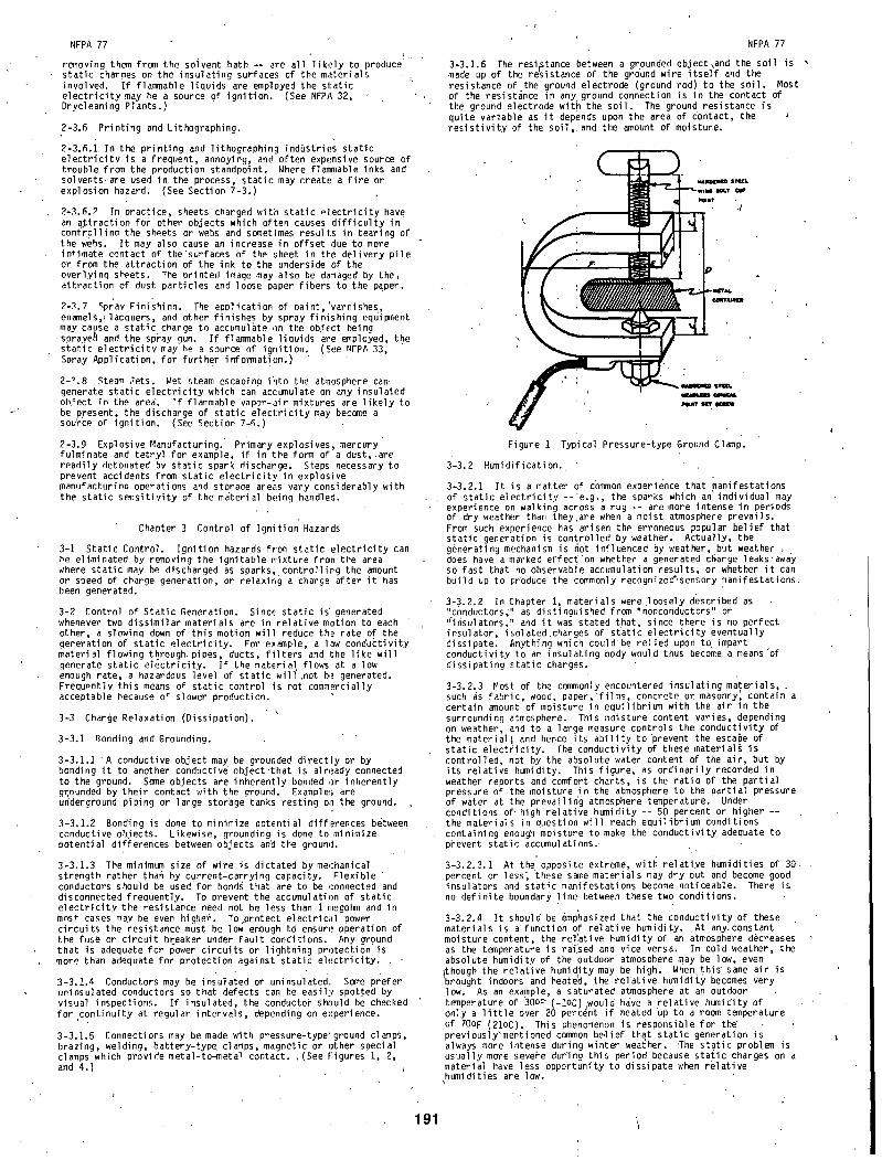
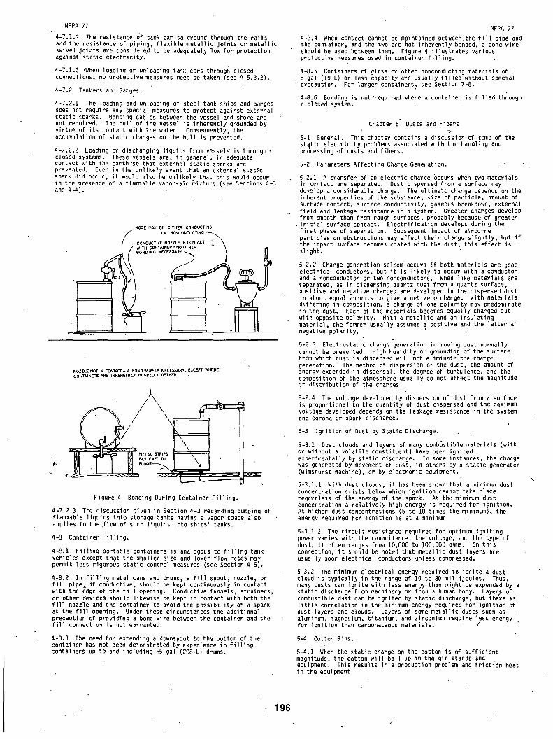
3-3.1.5 Connections may be made with pressure-type'ground clamps, brazing, welding, battery-type clamps, magnetic or other special clamps which provide metal-to-metal contact, .(See Figures 1, 2, and 4. )
I
191
NFPA 77
3-3.1.6 The resistance between a grounded object\and the soil is , made up of the r~sistance of the gro'und wire i tse l f and the resistance of the ground electrode (ground rod) to the soil. Most of the resistance in anyground connection is in the contact of the ground electrode wit h the soil. The ground resistance is quite variable as i t depends upon the area of contact, the res is t iv i ty of the soil, and the amount of moisture.
~ ~ IaZW
Figure I Typical Pressure-type Ground C1~p.
3'-3.2 Humidification.
3-3.2.1 I t is a matter of common experience that manifestations of static e lectr ic i ty - - 'e .g. , the sparks which an individual may experience on walking across a rug -- are more intense in periods of dry weather than they.are when a moist atmosphere prevails. From such experience has arisen the erroneous popular belief that static generation is controlled by weather. Actually, the gen•eratingmechanism is ~ot influenced by weather, but weather , does have a marked effect'on whether a generated charge leaks.away so fast that no observable accumulation results, or whether i t can build up to produce the commonly recognize~,sensory manifestations.
3-3.2.2 In Chapter 1, materials were loosely described as "conductors;" as distinguished from "nonconductors" or "insulators," and i t was stated t•hat, since there is no perfect insulator, isolated.charges of static e lectr ic i ty eventually dissipate. Anything which could'be relied upon to impart conductivity to an insulating body would thus become a means'of dissipating static charges.
3-3.2.3 Most of the commonly encountered insulating materials, such as fabric wood paper •films concrete or masonry~ contain a certain ~ount of moisture in equilibrium with the air in the surrounding atmosphere. This moisture content varies, depending on weather, and to a large measure controls the conductivity the material~ and hence its ab i l i ty to prevent the escape of static electr ici ty. The conductivity of these material~ is controlled, not by the absolute water content of the air, but by its relative humidity. This figure, as ordinarily recorded in weather reports and comfort charts, is the ratio of the partial pressure of the moisture in the atmosphere to the partial pressure of water at the prevailing atmosphere t~perature. Under conditions of' high relative humidity - - 50 percent or higher -- the materials in question will reach equ i l ib r i~ conditions containing enough moisture to make the conductivity adequate to prevent static accumulations. •
3-3.2.3.1 At the opposite extr~e, with relatiye humidities of 30 percent or le~s~ these s~e materials may dry out and become good insulators and static manifestations become noticeable. There is no definite boundary l ine between these two conditions.
3-3.2.4 I t should be ~phasized that the conductivity of ~hese materials is a•function of relative h~ id i t y . •At any constant moisture content, the rellative humidity of an atmosphere decreases as the t~perature is railsed and vice versa. In cold weather, the absolute h~ id i t y of the outdoor atmosphere may be low, even though the relative humidity may be high. When this s~e air is brought indoors and heate~, the rel'ative humidity becomes very low. As an example, a saturated atmosphere at an outdoor t~perature of 30op(-1oC),would have a relative h~ id i t y of only a l i t t l e over 20 percent i f heated up to a room t~perature of 70OF (21oC). This phenomenon is responsible for the" previously'mentioned common be.lief that static generation is alwa~ more intense during winter wea{her. •The static probl•~ is usually more severe during this period because static charges on a material have less opportunity to dissipate when relative humidities are low.

NFPA 77
3-3.2.5 Humidifying the abnosphere has proved to be a solution to static problems in some special circumstances, as where static has resulted in the adhesion or repulsion of sheets of paper, layers of floss, fibers, and the like. I t is usually stated that a relative humidity of about 5Q percent or higher will avoid such di f f icul t ies.
3-3.2.5.1 Unfortunately, i t is not practical to humidify all occupancies in which static might be a hazard, I t is necessary to conduct some operations in an atmosphere having a low relative humidity to avoid deleterious effects on the materials handled. High humidity can also cause intolerable comfort conditions in ooerations where the dry bulb temoerature is high. On the other • hand, a high humidity may advantageously af fect the handling prooert ies of snme mater ia ls, thus providing an addit ional advantage.
3-3.2.5.2 In some cases•localized humidi f icat ion produced by d i rec t ing a steam j e t onto c r i t i c a l areas may provide sa t i s fac to ry resul ts without the need fo r increasing the humidity in the whole room (see 7-2.6 and Section 7-6.)
3-3.2.6 I t does not fo l low that humidi f icat ion is a cure fo r al l s ta t ic problems. Some insulators are not susceptible to moisture absorption from the a i r , and high Humidity w i l l not not iceably decrease the r e s i s t i v i t y . Notable examples are the uncontaminated surfaces of some plastics and the surface of petroleum liquids. Such surfaces are capable of accumu]ating static charges even though the atmosphere may have humidity of up to 100 percent.
3-3.2.7 In summary, humidification may be a cure for static problems where the surfaces on which the sEatic electr ic i ty accumulates are those materials which can absorb moisture and which are not abnormally heated. For heated surfaces, and for static on the surface of oils and some other liquid and solid insulating materials, high humidity will not provide a means for draininq off static charges, and some other solution must be sought.
3-3.3 Increasing Conductivity.
3-3.3.1 Electrostatic charges may accumulate on the surfaces of low conductivitymaterials. By increasidg the conductivity, i .e . , lowering the res is t iv i ty , these charges can be relaxed before they can accumulate to a hazardous leve l .
3-3.3.2 In sol id mater ia l , i t may be possible to add a conductive material to increase the conduct iv i ty . For instance, carbon black has been added to some nlast ics tn increase the i r conduct iv i ty .
3-3.3.3 . In l i qu id fue ls , conduct iv i ty addit ives have been used fo r cont ro l l ing charge accumulation. These are polar mater ia ls, blended in to fue ls , usual ly at low concentrations. Conduct iv i ty levels greater than 50 picoseimens/meter (pS/m)* at use temoerature are general ly considered nonhazardous.
3 - 3 . 3 . 3 , 1 The e f fec t of conduct iv i ty decreases with decreasing temperature. I t is imoortant that enough addi t ive be used to assure sa t i s fac to ry conduct iv i ty at the lowest product use temperature.
3-3.3.3,2 I t is important to note that conduct iv i ty addit ives do not 'prevent the generation of s ta t i c e l e c t r i c i t y . They allow raoid charge re laxat ion, i . e . , the recombining with charges .of opoosite polarity. The us~ of conductivity additives must be in conjunction with bonding and grounding to provide a complete electrical path for charge relaxation.
3-3.4 Ionization.
S * I pS/m : i X 10 -12 .J')_ - i m - I
3-3.4.1 General. Under certain circumstances air may become suff ic ient ly conducting to dissipate static charges. In the use of all static eliminators, one must consider certain engineering problems such as environmental conditions (dust, temperature, etc.), and positioning of the device in relation to the stock, machine parts, and personnel.
3-3.4.2 Inductive Neutralizer (Static Comb).
3-3.4.2.1 A static charge on a conductive body is free to flow, and on a spherical body in space i t will distribute i tse l f uniformly over the surface. I f the body isno t spherical, the self-repulsion of the charg~ wil l make i t concentrate on the surfaces having the least radius of curvature.
q-3.a.P.? I f the body is surrounded by air (or other gas) and the radius of curvature is reduced to almost zero, as with a sharp needle point, the charge concentration on the point can produce ionization•of the air, rendering i t conductive. As a result, whereas a surface o f large diameter can receive and hold a high voltage, the same surface equipped with a sharp needle point can reach only a small voltaqe before the leakaqe rate equals the rate of generation.
192
NFPA 77
3-3.4.2.3 A "static comb" is a metal bar equipped with a series of needle points. Another variation is a metal wire surrounded with metallic t insel.
3-3.4.2.4 I f ,a grounded "static comb" is brought close to an insulated charged body (or a charged insulating surface), ionization of the air at the points will provide enough conductivity to make the charge speedily leak away or be "neutralized." This principle is sometimes employed to remove the charge from power belts (see Section 7-1), fabrics (see Section 7-2), and paper (see Section 7-3). (See Figure 6.)
3-3.4.3 Electrical Neutralizer.
3-3.4.3.1 The electrical neutralizer is a line-powered high voltage device which is an effective means for removing static charges from materials l ike cotton, wool, si lk, or paper in process, manufacturing, or printing. I t produces a conducting ionized atmosphere in the v ic in i ty of the charged surfaces. The charges thereby leak away to some adjacent grounded conducting body. f
3-3.4.3.2 Electr ica l neutral izers should not be used where flammable vapors, gases, or dust may be present unless approved spec i f i ca l l y fo r such locat ions.
3-3.4.4 Radioactive Neutralizer. •
3-3.4.4.1 Another method for dissipating static e lectr ic i ty involves the ionization of air by radioactive material. Such installations require no redesign of existing equipment. The fabrication and distribution, of radioactive neutralizers are licensed by the U.S. NuclearIRegulatory Commission (or Agreement • State Licensing Agency) which is responsible for the health and safety of the general population.
3-3.4.4.2 Radioactive substances are not of themselves a potential ignition source; hence, the location of such sources for purposes of static dissipation need not be restricted on the basis of possible flammability of the surrounding atmosphere. However, i f the radiation source is some sort of line-powered device, the location of the equipment must be restricted in the'same manner as for any other electrical device, in accordance with NFPA 70, NATIONAL ELECTRICAL CODE ®.
3-3.4.5 Open Flame. Ionization of the air can also be obtained by an open flame (see 7-3.4.6).
3-3.4.6 Ionization by any of the methods described in 3-3.4 is particularly adaptable to the processes discussed in Sections 7-1, 7.2 and 7-3.
3-4 Control of Ignitable Mixtures by Inerting, Ventilation or Relocation.
3-4.1 Despite planned efforts to prevent accumulation of static charges, which should be the primary aim of good•design, there are many operations involving the handling of nonconductive materials or nonconductive equipment which do not lend themselves to this bui l t - in solution. I t may then be desirable, or essential, depending on the hazardous nature of the materials involved, to provide other measures to supplement or supplant static dissipation fac i l i t ies , such as:
3-4.1.1 Where the normally ignitable mixture is contained within a small enclosure, such as a processing tank, an inert gas may be used effectively to make the mixture nonflammable. (See NFPA 69, Standard on Explosion Prevention Systems.) When operations are normally conducted in an atmosphere above the upper flammable l imit i t may be practicable to apply the inert gas only during the periods when the mixture passes through its flammable range.
3-4.1.2 Mechanical ventilation may be applied in many instances to dilute an ignitable mixture well below its normal flammable range. Also, by directing the air movement, i t may be practical to prevent the flammable solvents or dusts from approaching an operation where an otherwise uncontrollable static hazard would exist. To be considered r~liable, the mechanical ventilation should be interlocked with the equipment .to assure i ts proper operation.
i
3-4.1.3 Where a static accumulating piece of equipment is unnecessarily located in a hazardous area, i t is preferable to relocate the equipment to a safe location rather than to rely upon prevention of static accumulation.
NFPA 77
Chapter 4 Flammahle and Combustible Liquids
4-1 General. /
4-1.1 Flammable liquids may form flammable, vapor-air mixtures when heino hanrqed or in storage.
4-1.1.1 I f the liquid temperature is below i ts flash point, the mixture above its surface will be below the lower flammable l imit , or too lean to burn. A liquid 6andled at or somewhat above its flash point is more l ikely to have a flammable vapor-air mixture at any free surface. I f the temperature of the liquid is far above its flash point, the equilibrium vapor mixture at the free surface will he above the upper flammable l imit, or too rich to burn. However, when loading such a liquid into a gas-free tank, the vapor space will pass through the flammable range during loading. I f the vapor mixture is below or above the-flammable limits, i t will not ignite, even should an incendive spark occur.
4-I.1.2 Liquids with a very low flash point, such as gasoline, have, in temperate or tropical climates, a vapor-air mixture at the liquid surface far above the.upper flammable l imit. Consequently, even i f a spark occurs, ho ignition results. However, i f such liquids are handled at temperatures .only sl ight ly above their flash point, ignition.becomes a pdssibil ity. In temnerate climates, kerosene or other high flash point liquids are normally handled at temperatures well. below their f'lash points. Consenuently, the vapor-air mixture at the liquid .(urface is below the lower flammable limit and, here again, no ignition results even though a spark occurs. In the tropics, or when heated, kerosene or other high flash point liquids may reach temperatures at or above their flash points which will produce ~t flammable • , vapor-air mixture.
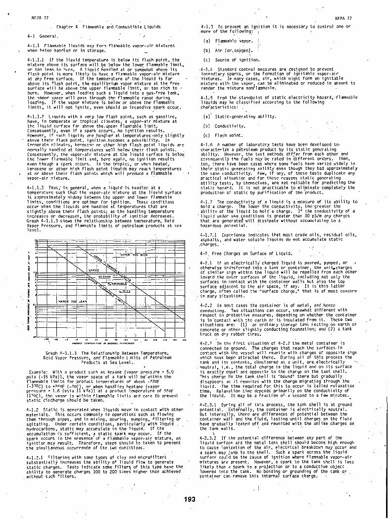
4-1.1.3 Thus," in general, when a liquid is handle(l at a , temperature such that the vapor-air mixture at the liquid surface is approximately midway between the upper and lower flammable limits, conditions are optimum for ignition. These conditions occur when the liquids are handled at temperatures that are sl ight ly above their flash points; asthe handling temperature increases or decreases, the probability of ignit ior decreases. Graph 4-1.1.3 shows the relationship between temperature, Reid Vapor Pressure, and flammable limits of petroleum products at sea level.
, J I I-, / I ~ I ;
" , I . . . . . . . . . . . . .
: r ~ '
i i . . . . . . . . . . . . \
J' ~. \ \
Graph 4- I . i .3 The Relationship Between Temperature, Reid Vapor Pressure, and Flammable Limits of Petroleum
Products at Sea Level.
Example: With a product such as hexane (vapor pressure = 5.0 psia (-35 kPa)), the vapor space of a tank will be'within the flammable limits for product temperature.(; of about -?8OF (-3~0C) to +PAoF (-RoC), or when handling heptane (vapor prPssure = 1.6 (psia 11 kPa)) at a product temperature of 55OF (1~0C), the vanor is within flammable limits and care t'o prevent static discharge should be taken.
a-I.2 Static is generated when liquids move • in contact with other materials. This occurs commonly in operations such as flowing them through pipes, and in mix'ing, pouring, pumping, f i l ter ing or agitating. Under certain conditions, particularly with liquid hydrocarbons, static may accumulate in the liquid. I f the accumulation-is suff icient, a static spaV'k may occur. I f the spark occurs in the presence of a flammable vapor~air mixture, an ignition may result. Therefore, steps should be taken to prevent the simultaneous occurrence of the two conditions.
4-1.2.1 Filtering with some types of clay and microfilters substantially increases the ab i l i ty of liquid flow to generate static charges. Tests indicate some fil i:ers of thi.s type have the ab i l i t y to generate charges 100 to 200 times' h!gher than achieved without such f i l ters .
1 9 3
NFPA 77
4-1.3 To prevent an ign!ition i t is necessary to control one or more of the following: 1
(a) Flammable vapor. •
(b) Air (or,oxygen). i
(c) Source of ignition.
,4-1.4 Standard control measures are designed to prevent incendiary sparks, or the formation of ignitable vapor-air mixtures. In many cases, air, which might form an ignitable mixture with the vapor, can be eliminated or reduced in amount to render the mixture nonflammable.
4-1.5 From the standpoint of static e lectr ic i ty hazard, flammable liquids may be classified according to the following characteristics: .
( a ) ~ Static-generating abi l i ty.
(b) Conductivity. '
(c) Flash point.
4-1.6 A number of laboratory tests have been developed to- characterize a p~troleum product by i t s static geherating abi l i ty . However, .the test methods dif fer from each other and consequentl# the fuels m~y be rated in different orders. Then, too, there have been cases where some fuels have varied widely in their static generating abi l i ty even though they had approximately the same conductivity. Few, i f any,.of these tests duplicate any practical situation and for these reasons static generating ab i l i t y tests, by themselves, are not reliable for predicting the static hazard. I t is not practicable to eliminate completely the production of static by purification of the 'product.
4-1.7 The conductivity i f a liquid is a measure of i ts ab i l i ty to hold a charge. The lower the conductivity, the'greater the abi l i ty of the liquid to~hold a charge. I f the conductivity of a
' l iqu id under use conditions is greater than 50 pS/m any charges that are generated will dissipate without accumulating to a hazardous potential.
4-1.7.1 Experience indicates that most crude oils, residual oils, asphalts, and water soluble liquids do not accumulate static
.charges.
4-2 Free Charges on Surface of Liquid. _ "
4-211 I f an electr ical ly charged liquid is poured, pumped, or , otherwise tr~insferred into a tank Or container, the unit~charges of similar sign within the liquid will be repelled from each other toward the outer surfaces of the liquid, including not only the surfaces in contact with the container walls but also the top surface adjacent to the air. space, i f any. I t i s t h i s latter charge, often called the "surface charge," that is of most concern in many situations.
4-2.2 In most cases the container is of metal, and hence conducting. Two situations can occur, somewhat different with respect to protective measures, depending on whether the container is in'contact with the earth or is insulated from i t . These two situations are: (i) an ordinary storage tank resting on earth or concrete or other sl ightly conducting foundation; and (2) a tank truck on dry rubbe~ tires.
4-2.3 In the f i r s t situation of 4-2.2 the metal container is connected to ground. The charges that reach the surfaces in contact with the vessel will reunite with charges of opposite sign which have be~n attracted there. During all of this process the tank and its contents, c~nsidered as a unit, are.electrically ". neutral, i .e . , the total charge in the liquid and on its surface is exactly equal and opposite to the charge on the tanR shell. This charge En the tank shell is "bound" there but gradually disappears as i t reunites with the charge migrating through the liquid. .The time required fo [ this to occur is ~alled relaxation time. Relaxation time depends primarily on the conductivity of the liquid. I t may be a fraction of•a second to a few minutes.
4-2.3.1 During all of this process, the tank shell is at ground potential. Externally, the container is electr ical ly neutral. But internally, there are differences of potential between the container wall and the f lu id, lasting until charges on the f lu id have gradually leaked off and reunited with the unlike charges on the tank walls.
N 4-2.3.2 I f the potential difference between any part of the liquid surface and the metal tank shell should become high enough to cause ionization of the air, electrical breakdown may occur and a spark may jump to the shell. Such a spark across the liquid surface could be the cause of ignition where flammable vapor-air mixtures are present. However, a spark to the tank shell is less l ikely than a spark to a projection or to a conductive object lowered into the tank. No bonding or grounding of the tank or container can remove this internal surface charge. -
i
NFPA 77
4-2.4 In the second situation mentioned in 4-2.2, the tank shell is highly insulated from the ground. The charge in the liquid ) surface attracts anequal and opposite charge to the inside of th~
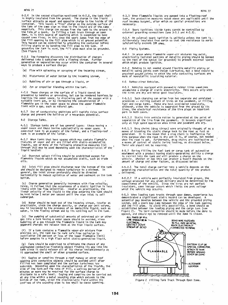
'container. This leaves a "free" charge on the outside surface of the tank of the same sign as that in the liquid and of thesame magnitude. This charge ~an escape from the tank to the ground in the form of a spark. In f i l l i ng a tank truck through an open dome, i t is this source of sparking which is suspected to have caused some fires; in this case the spark jumps from the edge of the f i l l opening to the f i l l pipe which is at ground potential. This hazard can be controlled by grounding the container before f i l l i ng starts or by bonding the f i l l pipe to the tank. I f
i roundino the tan~ is used, the f i l l pipe must also be grounded. See Figure 2.)
4-2.5 The foregoing discusses the distribution of charges delivered into a container with a flowing stream. Further generation or separation may occur within the container in several ways to produce a surface charge:
(a) Flow with splashi0g or spraying of the inceming stream,
(b) Disturbance of water bottem by the incoming stream,
(c) Bubbling of air or gas through a liquid, or
(d) Jet or propeller blending within the tank.
4-2.6 These charges on the surface of a liquid canndt be prevented by bonding or grounding, but can be rendered harmless by inertinq the vapor snace, by displacing part.of the oxygen witb'a suitable inert gas, or by increasing the concentration of flammable gas in the vapor space to above the upper flammable l imit with a gas, such as n~tural gas.
4-2.7 Use of conductivity additives wil l rapidly relax surface charge and prevent the build-up of a hazardous potential.
4-3 Storage Tanks.
4~3.1 S'torage tanks are of two general types: those having a vapor snace and those havina substantially no vapor space. A cone-roof tank is an example of the former, and a floating-roof tank is an exemple'of the lat ter.
4-3.2 When tanks that have spaces which may contain flammable mixtures of vapor and air are f i l led with static-accumulating liquids, one or more of the following protective measures ((a) through (h)) may be used depending upon the characteristics of the liquid handled:
(a) Overshot splash f i l i i ng should be prohibited except for flammable liquids which do not accumulate static, such as crude oils.
(b) Inlet f i l l pipe should discharge near the bottom of the tank and should be designed to reduce turbulence to a minimum. In general, the inlet stream preferably should be directed horizontally to reduce agitation of water and sediment on the tank bottom.
(c) Charge generation'generally increases with flow velocitw; hence, i t follows that the occurrence of a static ignition is less l ikely with low flow velocities. Insofar as practicable, the linear velocity of the liquid in the pipe entering the tank should• be. kept below 1 meter per second until the pipe inlet is well submerged.
(d) Water should be kept out of the inceming stream, insofar as practicable, sin~e the charge density, or charge per unit volume, may he increased by the presence of an immiscible l iquid, 'such as water, in the flowing stream and Uy its settling ou~ in the tank.
(e) The pumping of substantial amounts of entrained air or other gas into a tank having a vapor space should be avoided, since bubbling of a gas through the flammable liquid in the tank may geDerate charges and release them at the free liquid surface.
(f) I f a tank contains a flammable vapor-air mixture from previous use, the tank may he made safe from explosion by ventilation (50 percent or less of the lower flammable limit) before pumpinq in a high flash point static-generatina liquid.
(g) Care should be exercised to eliminate the chance of any ungroupded conductive floatable object finding its way into the tank since i t could release all of its charge instaBtaheously as i t approached the shell of other•g~ounded surface.
( h ) Gaginq or samplino through a roof manway or other roof opening with conductive objects should be avoided until after f i l l i n o has been completed and the surface turbulence has subsided. Depending upon the characteristics of the liquids, the size of the tank.and the rate of f i l l , a waiting period of 30 minutes or more may be required for the surface charge to dissipate to a safe level. Gaging and sampling can be carried out at ahy time within a metal sounding pipe which extends to the bottom of the tank, since the electrostatic f ie ld within the confines of the sounding pipe is too small to cause sparking.
194
NFPA 77
4-3.3 • When flammable liquids are pumped into a floating-roof tank, the protective measures noted above are applicable until the roof becomes buoyant, after which no special precautions are necessary, j
4-3.4 Spark ignitions inside tanks cann6t be controlled by external grounding connections (see 3-3:1 and 4-2.!).
4-3.5 An external spark ignition is unlikely unless the tank is , deliberately insulated from earth so that the resistance to earth
substantially exceeds 106 ohms.
4-4 Piping Systems.
4-4.1 In areas where flammable vapor-air mixtures may exist, electr ical ly isolated sections of metallic piping should be bonded to the rest of the system (or grounded) to prevent external sparks which might produce ignition.
4-4.2 Bonding is not needed around f lexible metallic piping or metallic swing joints even though lubricated, but a bond should be provided around joints in which the only contacting surfaces are made of nonmetallic insulating material.
4-5 Rubber-tired Vehicles.
4-5.1 Vehicles equipped with pneumatic rubber tires sometimes accumulate a charge of static electr ic i ty. This occurs only when the tires are dry and hence good insulators.
4-5.1.1 Such charging can arise from two separate and unfelated processes -- rol l ing contact of tires on the pavement, or f i l l i ng fuel and cargo tanks. These are best considered separately, although, since the vehicle is separated from the ground by i ts t ires, the electrical resistance of the t i re plays an important part in both cases."
4-5.,1.2 Static from vehicle motion is generated at the point of separation of the t i re from the pavement. I t becomes significant only at high speed operation when tires and pavement are dry.
4-5.1.3 Drag chains (drag straps) were originally thought of as a means of bleeding the static charge back to the road as fast as generated. I t is now known that a drag chain is ineffective for this purpose when the road is dry and i t is, of course, not needed when the road is wet. Furthermore, drag chains are ineffective as a means pf control of static during loading, as discussed below. Their u~e should not be required. '
4-5.2 During f i l l i n g the fuel tank or cargo tank of automotive equipment with a product having static-generating ab i l i ty a charge is carried into the tank and will produce a charge on the vehicle. Whether or not this can produce a hazard depends on the. amount of charge and other factors, as discussed below:
4-5.2.1 The total charge carried into a vehicle depends on the generating characteristics and the total quantity of the product delivered.
4-5.2.2 I f a vehicle were perfectly insulated from ground, the voltage produced for any given delivery would be determined by the capacitance of the vehicle. Since the tires are not perfect insulators, some leakage occurs which limits the peak voltage which the vehicle may acquire.
4-5.3 When loading tank trucks through'open domes, experience has demonstrated a significant static hazard can be developed. A potential may develop between the vehicle and the grounded piping system, an~ a. spark may jump between the edge of the tank opening and the f i l l pipe. To avoid this possibil i ty, a bond should be established between the loading piping and the cargo tank (see Figure 2), The bond connecti)on should be made before the dome is opened, and should not be removed until the dome is closed.
ALL PARTS OF RLL LINE S I ~ BE ~ ~ BOND WIRE FASTENED
N ~ TO FILL PIPE OR METAL C~[~/V~'ACT DOW ~ 1RACK ELECTRICALLY 5TRE~aJM ~ BOmb ~ C O N N E C T E D ~ TO RPING
BATTERY CLIP OR
o
/ ~I ~ \ - " SPECIAL CONNECFOR , J . . . . . !,& . . . . ~L \ ATTACH T0 TANK " I~ r L ~ M I ~ A O L E ~--~ \ BEI~DRE (~=E NING
-- ALTERNAE • I LOCAnON
, . ULI I J U " ' ~ ~ / / / _ _ - - - - - - / / / - - - - - / / ~
Figure-2 F i l l i n g Tank Truck Through Open Dome. /

NFPA 77 J
CONDUCTING OR NON-CONDUCTING HOSE f
/
, . . ..
Figure 3 Fil l ing or Emptying Tank Truck Through a Closed Connection.
4-F.3.1 The fixed end of the bond wire may 'be conn!.~cted to the f i l l pipe, to any part of a metal loading rack which is electr ical ly connected to the pipe, or to ground. I t is not necessary to bond around f lexible metallic joints or swivel joints" (unless of the insulating type) in the loading pipe. The attachment clip on the bond wire should be abattery clip or some other equivalent attachment- so made that i t can pull free, thus avoiding inadvertent damage which might result from driving the vehicle away without removing the bond.
4-5.3.2 Such bonding is not required: (1) when loading vehicles with products not having static-accumulaEing ab i l i t fes , such as asnhalt and cr. ude oi l ; (2) where tank v~hicles are used exclusively for transporting Class I I or Class I l l "liquids loaded at racks where no Class I liquids are handled; or, (3) where vehicles are loaded or unloaHed through closed connections, so that there is no release of vapor at a point where a spark could occur, irrespective of whether the hose or pipe used is conducting or nonconducting. (See Figure 3.) A closed connection is one where contact is made before flow starts and is broken after flow is completed. (See NFPA 321, Standard on Basic Classification of Flammable and Combustible Liquies, for information on the classification of liquids.)
4-5.3.3 Switch loadin•g is a term used to des•cribe a product being loaded into a tank or compartment which prev!ously held a•product of different vapor pressure. Switch loading can result in an ignition when low'vapor pressure products are put into a cargo tank containing a flammable vapor from pr-~vious usage, i .e . , furnace oil "loaded into a tank which last carried gasoline.
4-5.3.4 During "switch loading" or when ]oading products, . excluding those enumerated in 4-5.3.2 above, which may give off . vapors that are within the flamma'ble range (see Figure 2), the f i l l pipe should reach as close as possible to the bottoni of the tank being loaded, and ~referably be in conta~c with the bottom. I f the f i l l pipe does not, reach the tank bottom, the liquid velocity in the f i l l pipe should be limited to approximately 3 f t (0.9 m) per second until ,the outlet is submerged. I f the f i l l pipe reaches the bottom of the. tank or after the outlet of the f i l l pipe is covered~ the velocity may be increased to approximately 15-20 f t per second (4-5 m ~o 6 r~).
4-5.3.5 Where bottom loading is used, low velocity or splash deflectors or other devices should be used to prevent upward spraying of the product and to minimize surface turbulence.
' 4-5.3.6 All metallic parts of the f i l l .p ipe assembly'should'form a continuous electr ical ly conductive path downstream from the point of bonding. For example, insertion of a noncc, nductive hose equipped with a metal coupling on the outlet must b~ avoided unless the coupling is bonded to the' f i l l pipe. This is not required in bottom loading. \
4-5.3.7 Metal or conductive objects, such as gage tapes, sample containers., and thermemeters, should not be lowered into or susnended in a compartment while the compartment is being f i l l ed or immediately after, cessation of pumping. A waiting period of approximately one minute will generally permit a su~sbantial relaxation of the electrostatic charge. "
4-5.3.8 Care shouid be exercised 'to miniraize.the pc.ssibility of any. unbonded object entering into a tank. Prior to loading, tanks should he inspected ~and any unhonded objec.t removed.
4-5.3.9 Filters capable of removing micr.onC'sized particles are considered prol i f ic static generators. Therefore, a minimum of 3el-seconds relaxation time normally should he provided downstream of the f i l t e r . This means that i t should take at least 30 seconds for a particle of liquid to travel from the outlet of the f i l t e r element to the outlet of the f i l l pipe di.(;charge into the tank truck compartment. Relaxation time may be obtained by enlarging or lengthening the pipeline, by install ing a_retention chamber, or by reducina the f low rate.
i NFPA 77
4-5.3.10 Where conduct iv i ty, improver addit ives are used, reduced f low res t r i c t ions or re laxat ion may not be necessary but}bonding and grounding precautions need to be fol lowed.
4-5.4 No'external bond wire or bond wire integral with a hose is needed for the unloading of flammable l iqu ids into underground tanks through a closed connection (see Figure 3)~
4-6 A i r c ra f t . 'i "
4 - 6 . 1 Fueling and Refuel:ing of A i r c ra f t ' on the Ground..
4-6.1.1 When fuel ing a i r lc raf t , the a i r c ra f t should f i r s t be bonded to the tank truck, ' drum, fue l ing cabinet, hydrant or p i t , thus providing a low-resistance path to permit reuni t ing of separated charges; that is , so that charges del ivered in to the ' fuel tanks of the a i r c ra f t may reuni te with charges l e f t on the tank truck or other type of fue ler .
4-6.1.2 When fue l ing is by over-the-wing de l ivery , the fuel nozzle should be connected to a metal part bf the a i r c r a f t which is me ta l l i ca l l y connectedhto the fuel tank at a point-near the tank f { l l opening by means of a short bond wire and c l i p or plug.' This connection should belmade before the f i l l cap is removed and the nozzle is placed in the f i l l opening. I t shou,ld not" be detached unt i l f i l l i n g has been completed and the f i l l cap has been.replaced.
4-6.1.3 When fue l ing is by underwing de l ivery , the fue l ing is through a closed system. This closed system provides metal-to-metal contact and thus inherent bonding at the point of connection so that the bond connection mentioned in 4 -6 .1 .2 . i s not required. . '
4-6.1.41 I f nonmetallic conductive hose is used, i t should no t be regarded as a substitute for bonding.
4-6.1>5 When defue~Jng aircraft, the static-proteCtive measures should be the same as those taken during fueling operations.
4-6.1.6 Some regulatiogs require,' in addition to the bonding reauired in this section, that the aircraft and fueling syst~ be connected by wires to ground. However, in many locations grounds
"are not available and evidence does ,not indicate that g~ounding is necessary for protection against static ignition. (See NFPA 407,
Aircraft Fuel Servicing.)
4-6.2 Airborne Aircraft..
4-6.2.1 Bonding of aircraft parts to provide equalization of the potential between various, metallic structures of the aircraft is desirable. While such bonding is common, portions of aircraft may be insulated, either because of imperfect bonding or because they are incapable of being electr ical ly bonded ( i .e . , antenna lead-ins might be a source of static spark inside the aircraft structure when the antenna lead-in:is connected to i ts receiver through a capacitor). Unbonded portions constitute a static f i re hazard where flammable vapors are present and an explosion hazard where such flammable vapors exist within confined areas or structures of an aircraft.
4-6.2.2 High humidity conditions do not aid in th e dissipation of static electrical chargeslon airborne aircraft as is occasioned on objects rest!ng on the ground s~mply because of the absence of any continuous solid surface between the aircraft and the'ground on" which a moist film can beldeposited. In fact, when humidity reaches the saturation;point, an increase in precipitation static results. Small traces of water vapor in a film on an'ihsulator (as might be imparted by condensation) do, however, render some insulators conducting.
4-6.2.3 Static dissipators can only attempt to approach the theoFetical ideal which would be to discharge instantly the electrostatic charges generated on the aircraft so that there would be no difference of potential with the surrounding atmosphere. This is truesince ionization cannot start until the impressed potential gradients of the aircraft attain their ionizing threshold intensities. Static dissipators wi l l safely lower dangerous 'potentials from aircraft i f of proper design and installed in adequate number at electr ical ly strategic "locations.
4-6.2.4 I t should be stated expl ic i t ly that the development of static charges on airborne aircraft offers a fi~e O r explosion hazard only where flammable vapor-air mixtures exist and every - effort should be made to eliminate all constructions and procedures which could produce accumulations of such flammable vapor-air mixtures.
4-7 Tank Cars, Tankers and Barges.
4-7.1 Tank Cars.
4-7.1.1 When loading or unloading tank cars through open domes, the downspout should be of sufficient length to reach•the tank bottom (see 4-5".3.2 for Exception).
i
, I
195
NFP~ 77
'" 4-7.1.9 The resistance of tank car to ground ~hrough the rails and the resistance of piping, flexible metallic joints or metallic swivel joints are considered to be adequately low for protection against static electr icity.
4-7.1.3 .When loading or unloading tank cars through closed connections, no protective measures need be taken (see 4-5.3.2).
4-7.2 Tankers and Barges.
4-7.2.1 The loading and unloading of steel tank ships and barges does not require any special measures to protect against external static sharks. Bonding cables hetween the vessel and shore are not required. The hull of the vessel is inherently grounded by virtue of its contact with the water. Consequently, the accumulation of static charges on the hull is prevented.
4-7.2.2 Loading or discharging liquids from vessels'is through. closed systems. These vessels are, in general, in adequate contact with the earth'so that external static sparks are prevented. Even in the unlikely event that an external static spark did occur, i t would also he unlikely that this would occur in the presence of a flammable vapor-air mixture (see Sections 4-3 and 4-4).
HOSE MAY BE EITHER CONDUCTING OR NONCONDUCTING ~
CONDUCTIVE NOZZLE IN CONTACT - / WITH CONTAINER-NO OTHER
BONDING NECESSARY
NOZZLE NOT IN CONTACT- A BOND WIRE IS NECESSARY, ExcEPT WHERE CONTAINERS ARE INHERENTLY BONDED IOGETHER
Figure 4 Bonding During Container Fil l ing.
4-7.2.3 The discussion given in Section 4-3 regarding pumping of flammable liquids into storage tanks having a vapor space also applies to the flow of such liquids into ships' tanks.
4-8 Container Fil l ing.
4-8.1 Fill ing portable containers is analogous to f i l l i ng tank vehicles except that the smaller size and lower flow rates may permit less rigorous static control measures (see Section 4-5).
4-8.2 In f i l l i ng metal cans and drums, a f i l l spout, nozzle, or f i l l pipe, i f conductive, should be kept continuously in contact with the edge of the f i l l opening. Conductive funnels, strainers, or other devices should likewise be kept in contact with both the f i l l nozzle and the container to avoid the possibility of a spark at the f i l l opening. Under these circumstances the additional precaution of providing a bond wire between the container and the f i l l connection is not warranted.
4-8.3 The need for extending a downspout to the bottom of the container has not been demonstrated by experience in f i l l ing containers Op to and including ~5-gal (208-L) drums.
NFPA 77 4-8.4 When contact cannot be maintained between the f i l l pipe and the container, and the two are not Inherently bonded, a bond wlre should be used between them. Figure 4 illustrates various protective measures used in container f i l l i ng .
4-8.5 Containers of glass or other nonconducting materials of S gal (19 L) or less capacity are.usually f i l led without special precaut!on. For larger containers? see Section 7-8.
4-8.6 Bonding is not'required where a container is f i l led through a closed system.
Chapter 5" Dusts and Fibers
5-1 General. This chapter contains a discussion of some of the static electr ici ty problems associated with the handling and processing of dusts and fibers.
5-2 Parameters Affecting Charge Generation.
5-2.1 A transfer of an electric charge occurs when two materials in contact are separated. Dust dispersed from a surface may develop a considerablecharge. The ultimate charge depends on the inherent properties of the substance, size of particle, amount of surface contact, surface conductivity, gaseous breakdown, external f ield and leakage resistance in a system. Greater charges develop from smooth than from rough surfaces, probably because of greater
. i n i t i a l surface contact. Electrification develops during the f i r s t phase of separation. Subsequent impact of airborne particles on obstructions may affect their charge slightly, but i f the impact surface becomes coated with the dust, this effect is slight.
5-2.2 Charge generation seldom occurs i f both materials are good electrical conductors, but i t is l ikely to occur with a conductor and a nonconductor or two nonconductors. When like materials are separated, as in dispersing quartz ~ust from a quartz surface, positive and negative charges are developed in the dispersed dust in about equal amounts to give a net zero charge. With materials differing in composition, a charge of one polarity may predominate in the dust. Each of the materials becomes equally charged but with opposite polarity. With a metallic and an insulating material, the former usually assumes ~ positive and the latter a" negative polarity.
5-2.3 Electrostatic charge generation in moving dust normaliy cannot be prevented. High humidity or grounding of the surface from which du~t is dispersed will not eliminate the charge generation. The method of dispersion of the dust, the amount of energy expended in dispersal, the degree of turbulence, and the composition of the atmosphere usually do not affect the magnitude or distribution of the charges.
5-2.4 The voltage developed by dispersion of dust from a surface is proportional to the quantity of dust dispersed and the maximum voltage developed depend§ on the leakage resistance in the system and corona or spark discharge.
5-3 Ignition of Dust by Static Discharge.
5-3.1 Dust clouds and layers of many combustible materials (with or without a volatile constituent) have been ignited experimentally by static discharge. In some instances, the charge was generated by movement of dust, in others by a static generator (Wimshurst machine), or by electronic equipment,
5-3.1.1 With dust clouds, i t has been shown that a minimum dust concentration exists below which ignition cannot take place regardless of the energy of the spark. At the minimum dust concentration a relatively high energy is required for ignition. At higher du~t concentrations (5 to 10 times the minimum), the energy required for ignition is at a minimum.
5-3.1.2 The circuit resistance required for optimum igniting power varies with the capacitance, the voltage, and the type of dust; i t often ranges from 10,000 to 300,000 ohms. In th4s connection, i t should be noted that metallic dust layers are usually poor electrical conductors unless compressed.
5-3.2 The minimum electrical energy required to ignite a dust cloud is typically in the range of 10 to 80 mill i joules. Thus, many dusts can ignite with less energy than might be expended by a static discharge from machinery or from a human body. Layers of combustible dust can be ignited by static discharge, but there js l i t t l e correlation in the minimum energy required for ignition of dust layers and clouds. Layers of some metallic dusts such as aluminum, magnesium, titanium, and zirconium require l~ss energy For ignition than carbonaceous materials. /
5-4 Cotton Gins.
5-4.1 When the static charge o n the cotton is of sufficient magnitude, the cotton will ball up in the gin stands and equipment. This results in a production problem and fricti'on heat in the equipment.
\
196

NFPA 77
5-4.2 The generation of s ta t ic on the cotton can be'minimized by the in t roduct ion of moisture or an an t i s ta t i c agent.
5-4.3 The bonding and grounding of cotton gin equipment w i l l not prevent or remove the s ta t i c accumulation from the cotton being processed. 3
5-5 Control Measures. The principal methods of controlling static electr ici ty associated with dusts are:
1. "Use only conductive equipment and keep all components grounded.
2. Avoid projections and probes that could lead todischarges between a charged dust pile and a probe.
3. Ionize the air to provide a means of discharging the dust.
4. Avoid a flammable condition by inerting the container.
Chapter 6 Gases
6-1 General.
6-1.1 Gases not contaminated with solid or,liquid particles have heen found to generate l i t t l e , i f any, electrif ication in their flow.
6-1.2 When the flowing gas is contaminated with metallic oxides or scale particles~ etc,, or'with liquid particles or spray, electrif ication may result. A stream of such particle-containing gas directed against a conductive object will charge thb latter unless the object is grounded or bonded "to the discharge pipe.
6-1.3 When any gas is in a closed syst~a of piping and equipment, the system need not be electrically conductive or electrically bonded, except that electrically isolated conductive sections should not be used.
• 6-2 Air Under Pressure. Compressed air containing particles of ,condensed water vapor often manifests strong electrif ication wheh escaninn.
6-3 ~arbon Dioxide. Carbon dioxide, discharged as a liquid from orifices unde~ high pressure (where i t in~ediately changes to a gas and "snow"), can result in static accumulations on the discharge device and the receiving container. High pressure carbon dioxide should not be discharged into flammable atmospheres because i t presents a high risk of ignition.
6-4 Hydrogen-Air, Acetylene-Air Mixtures. Hydrogen-air and acetylene-air mixtures may be ignited by a spark energy of as l i t t l e as 0.017 millijoule." In the pure state, no static charges are generated by the flow of hydrogen. Howev~r,'as gaseous hydrogen is commercially handled in industry, such as f lowing throuoh pipel ines, discharging through wilves at f i l l i n g racks in to nressure containers, or f lowing out of containers throuQh
• nozzles, the" hydrogen may be/found to contain par t ic les of ox4de , carr ied o f f from the inside of pipes or containers. In th is
contaminated state, hydrogen gas w i l l generate s ta t i c , and may be ignited.
~6-~ LP-Gas.
~-5.1 The l iquef ied petroleum gases (LP-Gases) behave in a manner s imi lar to t f iat discussed in 6-1.1 i n t h e gas phase and 6-1.2 in the mixe~ nhase.
6-~.P Bondino is not reauired where vehicles are loaded or unloaded through closed connections, so that there is no release of vapor at a point where a spark should occur, i r respect ive of whether the hose or pipe used is conducting or noncDnducting. A closed connection is one where contact is made before f low star ts and is broken af ter f low has ended.
NFPA 77
Chapter 7 Industr ia l and Commercial Processes
7- i Beits~
7-1.1 General. Rubber or leather f l a t belts or vee belts used for the transmission of pbwer or belts used for the t ranspor tat ion of sol id material may generate s ta t i c and warr'ant c o r r e c t i v e measures i f there is a p o s s i b i l i t y that ign i tab le atmospheres, dusts, or f ibers may be present.
7-1.2 Flat Belts.
7-I ' .2.1 Rubber or leather f l a t belts are usual ly dry and good insulators because f r i c t i o n causes ~hem to operate a t temperatures higher than the surrounding atmosphere. Stat ic generation occurs where the be l t leaves the pu l ley and may occur with e i ther conducting or nonconducting pul leys.
7-1.2.2 Charge accumulation may be prevented by employing belts of the an t i s ta t i~ type that are made of conductive mater ials. I t may also be prevented by applying a special type of conductive dressing to the be l t . To be e f fec t i ve , these dressings must. be renewed f requent ly .
7-1.2.3 A grounded s ta t i c comb placed with the poi'nts close to the inside of the bel t 'and a few inches away from the point where i t leaves the pul ley w i l l be e f fec t i ve in draining o f f most of the s ta t ic charge (see Figure 6).
7 - i .3 Vee Belts. Vee belts are not as susceptible to hazardous accumulations of e lec t r i c charge as f l a t bel ts. Under certa in ' condit ions of temperature and humidity, however, a vee bel t dr ive may generate a s ign i f i can t quant i ty of s ta t ic e l e c t r i c i t y . Where flammable vapors are present i t is safe pract ice to employ vee belts of the conducting type~ Conducting type vee belts should be kept free of accumulations of nonconducting mater ia l . In areas where flammable vapors are l i k e l y to be present, d i rec t drives are preferable to vee bel ts , although i t is general lyconsidered that the r isk frora the standpoint of s ta t i c is small.
7-1.m ~Conveyor Bel ts.
7-1.4.1 Belts used fo r the t ransportat ion of sol id material usual ly move at slow ve loc i t y and normally would not be s ta t i c generators. However, i f the materials transported are heated or are very dry, or i f the be l t operates in a heated atmosphere or moves with high ve loc i t y , generation may be s ign i f i can t .
7-1.4.2 Mater ials sp i l led from the end of a conveyor be l t into a hopper or chute may carry a s ta t i c c~arge. I f such charges cause d i f f i c u l t y , the bel t support and terminal pul leys should be e l e c t r i c a l l y bonded to the hopper. Stat ic el iminators ins ta l led close to the end of the conveyor where the materials sp i l l o f f may also be helpfu l .
CUNTAmER FOR C~ATRtG MATERtAL
- STATIC I [ LI~VJ NAT0 R$ HGDpE R STATIC E U M I N A T O R S , -
GROUN~ *,--ClJ~I'H~ I T O M ( T A L ' I~IIO U 0 U 0 ~ ~ 0 .~ U ~-~ u ~J ~ N £
"~.--FLOOR L INE ~
CONVENIENT GROU/~D
Figure 5 Grounding of Cloth Coating Machine (Metal Frame) Showing Location of Sta t ic El iminators.
197
. d I

NFPA 77
T t m " [ L I ~ e l iAR MAYe~ H ~ O ON G R ~ O ~ S O~ AIOIOLY SUPPORTED.
I o
(' o
.~.....__.~
~ o m L [ n ROLL
/ ( ( o ....
COAR[¢T LOCATIOa OT" STAtiC ¢OOL[¢Iro~ (TmS[L ~R}
B
. . . . .
D
NFPA 77
• Figure 6 Static Removal from Nonconducting Materials.
• GROUNDED IDLER ROLLS
T I N S E ~
GRAVURE PRINTING ROLLS Figure 7 Static Removal from Printing Rolls.
7-1.5 Pulleys and Shafting.
7-1.5.1 Metal pulleys will pick up a charge equal and opposite to that carried by a belt that runs over them, and will communicate this charge to the supporting shaft and thence through bearings to the emHpment and the earth. Tn special cases involving nonconducting components that isolate metal parts, i t may be necessary to bond or ground the isolated metal portions of the equipment.
7-1.5.2 I t has been found that lubricated bearings are usually suff ic ient ly conductive tq allow a static charge to leak o f f the shafts. However, the conductance' across hearings operating at very high RPM may not be suffi-cient to prevent accumulation of static charge when the charge generation rate is high. For this reason, shafts rntatinQ at yery high RP~ should be hnnded or grounded through a sliding contact to the housing.
7-2 Coating, Spreading, and Impregnating.
7-2.1 Coating, spreading, and impregnating operations are quite similar to each nther in that they each involve the application of solutions such as paints, lacquers, rubber compounds, "dopes," and varnish to fabrics, paper, or other materials. Various methods of applying the coating or impregnating material are employed. These include a doctor blade or knife, flowing ro l l , squeeze rol ls, or calendar rol ls and the method used is determined by the viscosity and temperature of the coating of the impregnating solution, the soeed of the machine, the thickness of the coating desired or the depth Of the impreQnation. Figure ~ shows a typical;cloth coat'ing machine.
7-2.2 Charge accumulations on the coated material depend to a considerable degree on the mater'ials of which the rollers are made. In some cases, oharge acEumulations can be greatly reduced by the selection of materials used for the rol ler. For example, conductive rol ls in place of rol ls covered with nonconductive materials may be helpful.
J 7-2.3 The operator should wear conductive footwear. Working platforms around coating machines should be conductive and grounded, and kept clean so that the operator does not become insulated from ground. ""
7-2 4.,When flammable liquids are employed in the process, definite precautions must be taken against possible ignition of flammable vapor-air mixtures. Static eliminators or neutralizers (see Figure 6) should be installed where the rolls of materials are unwound or where the webs pass over the roller or under spreader knives or doctor blades. See Figure 6 for positions of maximum effectiveness. All conductive parts of a machine should be bonded together, and unless the machine is i'nherently grounded, the frame of the machine should be permanently grounded.
7-2.5 Where flammable liquids are used, adequate forced ventilation shoul.d be provided for the area and the equipment to prevent flammable vapor accumulations. (See NFPA 34, Dipping and Coating Processes.)
7-2.6 I f humidification is not injurious to the process, maintenance of relative humidity of 50 percent or greater wil l be most helpful in the mitigation of static accumulations. Local humidifi,cation and the installation of steam jets at the feed end of the machine and at other points of static generation have been found in some cases to be a practical means of static control.
7-2.7 Solvent containers such as hoppers should be enclosed and preferably f i l l ed through a closed piping system.
7-3 Printing and Lithographing.
7-3.1 General. There are electrostatic problems associated with the printing and lithographing industry, and they may be addressed as shown in 7-3~2 through 7-3.4.9.
/
7-3.2 Paper.
7-3.2.1 The character of the paper surface has a great deal to do with the amount of static generated. Paper will acqdire static charges in the following processes: folding machines, die cutting, eyeletting,-deckling, pebbling and roughing, laminating; perforating, stapling, and tipping.
7-3.2.2 The hygroscopic quality of the paper is also determined to some extent by the character of the surface of the paper, which likewise has a distinct bearing on the generation of static by the paper. The more water content in the paper the less will be the amount of static generated. The di f f icul t ies in processing cellulose acetate sheets which are moi~tureproof is an excellent example in support of this statement.
1 9 8

NFPA 77
7-3.2.3 I f ali paper, used in the paper industry were in equilibrium with the air at a relative humidity of 70 percent o r more, there would probably be l i t t l e need for other means of s•tatic control. However, in the attempt to reduce the generation of static by increasing the moisture content, other production
t problems are sometimes.introduced because paper will change in dimension and f l e x i b i l i t y witHchanges in moisture and registration defects may result. ~The in!< drying rates may also be affected. . .
7-3.3 Inks.
7-3.3.1 The inks used in l e t t e r presses and l i thoilraph presses , contain only s l i gh t l y vo la t i l e solvents having f lash points in the 3{~OoF (14OoL) to aOOoF (2F14oL) range a~d present l i t t l e f i r e or explosion hazard. High speed pr int ing or rotogravure presses and flexograph presses require the use of low f lash point solvents havino flashpoints in the 'range of 20OF(-4oc). to . lPOOF (49oc); Fires can occur "due to the. use of tFe low flash '• point solvents whose vaporscan be ignited by static sparks or other ignition sources. . • "
7-3.4 Presses. ',
7-3.4.1 A great deal of static is generated by the paper running through the press, when i t is pulled fr~n a rol l or stack, when i t touches the rol l or feeder device which carries i t to the printing surface, during the actual impression, or in any of the handling" equipment provided hetween the impressibli and the ~inal deliver~/ roll" or stack. Printing 'on plastics, vinyls and other synthet ic. materials causes more static problems than printing Or p a p e r . .
7-3.4.2 The most common method of removing'static electr ic i ty from presse~ is by grounding, although grounding the framework in." i tse l f is frequently not sufficient-protection against static. '~ ° Static collectors or neutralizers are commonly used in close proximity to the paper as described in 3.-3.4. However, the elimination of.static at any one point in the printing operation ' does not prevent the generation of static in the tatter steps of the process and static neutralizers may be necessary at a number of locations. For fast running presses, such as passive neutralizers, tinsel wrapped around a bar or grounded points spaced 0.5 to 1 in. (12.70 to 25.40 mm) apart have been found to be effective. As with all neutralizers, positioning is important. The neutralizer should be spaced from 0.5 to I in. (12.70 to 25.40 ram.) away from the web and located as f~r as possible from grounded metallic press par.ts and areas where•the web is supported by rollers.
7-3.4.3 When tin~el bars are used i t is necessary to replace tinsel when i t is damaged or, on presses using a paraffin spray,
• when i t hecnmes coafpd with wax." Static collectors are fr.equently attached to the f l y to assist in remov~in( static fr, om the delivered sheets.
7-3.4.4 Humidification is one of the most successfui methods of cont~iolling static e lectr ic i ty (see 3-3.2). The amount of moisture required and the method of introducing i t in the air differs somewhat with the paper being run and local pressroom conditions. Usually e ranqe from 45 percent to 60 percent relative humidity is most practical. In plants with ventilating systems humidification is comp'aratively simple and, in others, moisture is introduced most easily by means of escaping steam.
7-3.4.5 In' addition to the above method;; of controlling static, a very comon device used on presses is the open gas flame. This, of course, can only be used in presses using inks of low vo la t i l i t y . The open flame is placed across the press at the delivery end so as to allow the paper to pass through the flame
• Quickly or very close to the heater. In every case where a gas flame is used for static elimination, the burner should be interlocke~ with the press so that the fiame will be out when the press is stopped. I t is necessary to make sure that the pi lot of the burner cannot touch the edge of the paper.
7-3.4.6 The electric neutralizer is used frequently for the elimination of static on all presses, but more particularly on rntary-typ~ Dresses •(see 3-3.4, Ionization). Ink spray from the ends 9f the rol'Is tends to accumulate on the" ends of the neutralizers and i t is important that they be kept reasonahly clean at all times because heavy ink deposits have caused , electrical breakdown of the neutralizers in a few cases.
7-3.4.7 Higher operating sl)eeds have resulted in the.development of the enclosed ink fountain which makes for a much safer press. The e•limination of the flammable vapors by proper local ventilation is probably the best solution to eliminating f.ires on these presses. Conditioned air is conducted to the presses and exhausted from the paper as i t passes from the printing cylind'er. This not only assists in the rapid dryinc~, hut keeps the vapors below the lower f}ammable limits.
7-3.4.8 From the f i re standpoint, presses o~= slow.speeds do not present the static problem exhibited in high-speed presses. Inks used on flat-bed nresses are nearly always of low vo la t i l i t y . However, the static electr ic i ty problem from the production standpoint s t i l l exists. This type of press, using'i~dividual ~"
199
j NFPA 77
sheet paper, is used for mul t icolor work when i t is f requent ly necessary to run work through two or more presses. The problem of exact register as well as a satisfactory de]ivery of the individual sheets from the f l y is affected by static buildup in the printing. Even releasing the sheet from the tympan is
'sometimes d i f f i cu l t . One of the most •satisfactory treatments for adhesions to the tympan is the use of glycerine and acetic acid to dampen i t . ! ,
7~3.4.9 With dry paper, in a dry atmosphere, a rotogravure press can become a static generatorL A rubber roll is pressed with as much as 4 tons (907 kg) of. pressure against a copper etched ro l l , which revolves in a volati le ink, and the paper passes between the two rolls. In a multicolored press there is a similar arrangement for each color. The generation of static can sometimes be reduced by reducing the pressure between the rol ls and changing the angle at which the paper enters the rol ls to lighten i t s contact with each roll~ Increasing paper and ink conductivity and press room air humidification are also effective in reducing static effects ' on rotogravure presses. For more complete control, however, a static eliminator or neutralizer covering the fu l l width of the web at the delivery si~e of each impression rol ler is usually necessary.
7-4 Mixing and Blending Operations.. 4
7-4.1 In the mixing and blending of fiammable liquids, or of particulates in a flammable liquid, one of the more common methods employed to drain off static is to bond and ground-all metal parts and all moving parts of "the equipment. Consequently, metal and other conductive material should be used as. fa r as possible in design of components that are contacted by the material being processed, although this may not prevent the accumulation of static charge on the mixed material.
7-4.2 Bondiilg and grounding as recommended wil'l not romove'the free charge on the surface of the liquid. (See Section 4-2.)
7-4.3 Jet mixing and propeller mixing in tanks may generate charges~ Care should be taken to avoid agitating a possible layer of water at the bottom of flammable liquid tanks~ "The jet or pro'peller stream should be directed so as not tobreak the surface. Jet mixing nozzles should not be used for f i l l i ng tanks. when the nozzles are above the liquid surface. Where flammable mixtures may be encountered above the liquid surface, inert gas blanketing may be employed. (See NFPA 69, Standard,.on Explosi•on Prevention SystemsL) ;
7-4.4 Floating-roof tanks eliminate the vapor space and, therefore, are especially desirab!e for hazardous b!~nding service
7-4.5. Good housekeeping is of prime importance'.fh areas where dust or powders from the oper,ations are produced. The building and equipment should be designed to eliminate shelves and ledges and similar places where such materials can accumulate.
7-4.6 Care should be taken to prevent tramp metal, tools or loose hardware from getting into the ducts and containers.
7-4.7 In the manufacture of lacquers and coating materials, plastic powders or pellets are dissolved in solvents. The plastic materials and the solvents are usually nonconductive but in the blending and mixing opeation, static generation can be high especially at the start of the operation. The charge generation can be reduce:d by using conductive solvents or by incorporating conductivity additives in nonconductive solvents.
7-5 Film Casting and Extrusion. 7-5.1 In'the manufacture of thin films thegeneration of static charg~may be appreciable especially when nonconducting coating materials are employed. When conductive coating materials are used, the hazard increases as the solvent is evaporated'from the product unless the ffnished product is at'so conductive. The static charge on the product can be reduced'by ionizing'the air in the immediate v ic in i ty : Ionization can be achieve~ by the use of stati~ combs, tinsel brass or. by the use of radioactive materials.
7-6 Steam J~ts. . . ' . . •
7-6.1 Surfaces on which steam condenses may accumulate static unless the surfaces are bon'ded to the discharging pipe•or both units are grounded. A resistance between connecting parts of 106~ohms or less should be adequate. I f flammable vapor-air mixtures are l ikely to be present, steam jets should be avoided. Also, when a steam eductor is used to. yeDtilate a tank containing a f~lammable vapor, the eductor should be used so that i t wil l pull the vapor out of the tank (not blow•steam into the tank) and i t should be electr ical ly bonded to the tank.
7-6.2 When steam cleaning constitutesJa hazard,'all pipes or nozzles through which steam is discharged should•be bonded to the equipment being steamed or the two objects should be connected to, ground. ! 7-7 Spray Application of Flammable and Combustible Materials. (See NFPA 33,: Spray Application Using Flammable and Cembustibie Materials.)
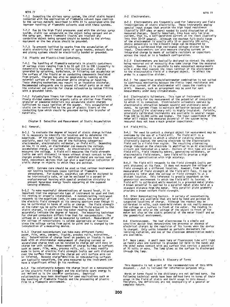
NFPA 77
7-?.1 Excepting t~e airless spray system, the chief static hazard connected with the application of flammable solvent base coatings by the various methods described in NFPA 33 is associated with the improper handling of flammable solvents used with these systems.
7-7.2 Due to the high f luid pressures used with the airless spray system, static can accumulate on the object being sprayed and on the spray gun. Where flammable liquids are invqlved any conductive object being sprayed should be bonded to the airless equipment or the two pieces should be grounded.
7-7.3 To prevent ignition by sparks from the accumulation of static e lectr ic i ty all metal parts of spray booths, exhaust ducts and piping systems should be electr ical ly bonded or grounded.
7-B Plastic and Plastic-Lined Containers.
7-R,1 The'handling of flammable materials in plastic containers of various sizes ranging from 5 to 55 gal (19 to 208 L)capacity is potentially hazardous. While f i l l i ng the.container, charges generated by splashing, turbulence, or f i l ter ing can accumulate on the surface of the liquid or on conducting components insulated from ground. Charges may also be generated by rubbing on the external surface of the container while shipping or handling. These charging mechanisms may result in an incendive discharge. Recommended safeguards are to ground all metal parts on or near the container and provide for charge relaxation by bottom f i l l i ng with a grounded lance,
7-8.2 Polyethylene liners for fiber drums which are f i l l ed with f inely divided combustible organic salts or similar free flowing granular or powdered materials may accumulate static charges sufficient to cause ignition of the powder. This accumulation of static can be controlled by the use of plastic liners of the conducting type which should be grounded during the transfer of materials.
Chapter 8 Detection and Measurement of Static Accumulation /
8-I Aeneral.
8-I.1 To evaluate the degree of'hazard of static charge buildup i t is necessary to identify i ts location and to determine i ts magnitude. Of the many types of measuring devices that are available, most fa l l into one of the following categories: electrometer, electrostatic voltmeter, or f ie ld mill. Depending on how i t is used, an electrometer can measure the voltage, accumulated charge, or current. An electrostatic voltmeter measures the voltage. A f ie ld mill measures the f ie ld strength (volts per unit distance) in space without direct contact to the charges producing the f ie ld. In addition there are various hand held, noncontact devices that can give a qualitative indication of static charge nn nhJects to which they are pointed.
NOTE: Extreme care should be used so that neither instruments nor testing techniques cause ignition of flammable atmospheres. For example, apparatus can often be designed to be intr insical ly safe, or can be enclosed in a purged or explosionproof housing with special protective circuitry to prevent hazardous energy levels appearing at the exposed sensing elements.
8-1.2 To make meaningful determinations of hazard level, i t is important tha~ the appropriate type of instrument be used and that i ts re~ding be nroperly interpreted. A noncontracting instrument responds to the magnitude (and, ,in some cases, the polarity) of the electric f ield strength at i ts sensing aperture even thobgh i t may be calibrated in terms of volts or charge, The f ie ld strength at the meter may be quite different from the f ie ld adjacent to the static charges, in which case the meter reading does not accurately indicate the degree of hazard. The measuring technique for charged conductors differs from that for nonconductors..The voltage on a conductor can be measured by contact. Measurement of the voltage of nonconductors is seldom appropriate or feasible since the voltage varies from point to point and is changed by the introduction of a measuring device.
8-1.3 Charged nonconductorscan take many different forms: paper, fi lm, webs, powders, liquids~ process rol ls, extrusions, e t c . Determination of charge level on powders or liquids is best made with an electrometer measurement of charging current or accumulated charge that can be related to charge per unit mass or charge oer unit volume. Measurement of charge buildup on surfaces such as paper, fi lm, webs, process rol ls, etc. is most readily made in terms of electric f ie ld strength (volts per unit distance) over the surllace from ~hich the charge per unit surface area can be inferred. Because charge'densities on nonconducting surfaces are typical ly nonuniform, the area measured by the instrument can have a significant effect ~n its readings.
8-1.4 The relationship between the charge level on a nonconductor or the electric f ie ld strength and the available spark energy is nnt defined as is the caseilfor conductors. Empirical relationships have been developed for some applications such as the handling of flammable liquids and the processing of plastic fi lm in a flammable environment.
NFPA 77 8-2 Electrometers.
8-2.1 Electrometers are frequently used for laboratory and f ie ld investigations of static electr ic i ty. These instroments employ special input stages that provide the high input resistance (typical ly 1014 ohms or more) needed to avoid dissipation of the measured charges. Equally important, they have very log bias current, that is, a self-generated current at the input (typical ly less than 10-14 ampere). ,Although the maximum full-scale range of the electrometer is usually only 10 or possibly 100 volts, static potentials in the ki lovolt range can be measured by attaching a calibrated high resistance voltage divider to the input. Electrometers can also measure charging current or integrated charge by means of suitable resistors or capacitors across the input or in a feedback configuration.
8-2.2 Electrometers are basically designed to contact the object being measured and of necessit~ draw some •charge from the measured object. However, i t is possible to make noncontact measurements with a probe that exposes the input terminal of the electrometer to the electrostatic f ie ld of a charged object. In effect the probe is a capacitive divider.
8-2.3 The capacitive probe/electrometer combination is not suited to continuous monitoring because the $inite input resistance and
.the bias current of the electrometer will cause the reading to dr i f t . However, such an arrangement may be used for spot measurements under many circumstances.
8-3 Electrostatic Voltmeters. This type of instrument is suitable only for the measurement of the potential of conductors to which i t is connected. Electrostatic voltmeters operate by electrostatic attraction between movable "and stationary metal vanes. No current flows to maintain deflection because one set of vanes (usuall~the stationary set) is highly insulated. Portable, accurately calibrated instruments are avail able in several ranges from 100 to 10,000 volts and higher. The input capacitance of the meter will reduce the measured potential i f the system being measured does not have a much greater capacitance.
8-4 Field Mills.
8-4.1 The need to contact a charged object for measurement may be overcome by the use of a f ie ld mil l . The f ie ld mill is a noncontacting device in which a shield or rotating shutter alternately exposes the sensing electrode to the electrostatic f ie ld and to a f ield-free region. The resulting alternating charge induced on the electrode is ~nplified in an AC electronic circui t and indicated on a meter. Devices of this type are called f ie ld mills, f ie ld intensity meters, generating voltmeters, or electrostatic f ie ld meters. Some f ie ld mills provide a high degree of sophistication with high accuracy.
8-4.2 The f ie ld mill responds to the f ie ld strength (volts per unit distance) at i ts face. I t does not measure the voltage or f ie ld s~rength at a different location. However, from the measurement of f ie ld strength at the f ie ld mill face, i t may be possible to infer what the voltage or f ie ld strength is at a distant location. This inference is greatly dependent on the geometrical environment in which the f ie ld mill is located. A f ie ld mill is calibrated while mounted in a grounded metal plate. A known potential is applied to a parallel metal plate held at a standard distance from the meter. This parallel plate geometry provides a known uniform f ie ld strength.
8-5 Other Noncontacting Devices. A variety of noncontacting instruments are available that are held by hand and pointed at suspected locations of charge. Although the readout may be calibrated in volts, such hand-held meters do not really measure the voltage on a surface in front of the meter. The reading is dependent not only on the voltage of the object in front of the meter but also on the static potential of the meter i t se l f and on the geometrical environment.
8-6 Electroscopes. The leaf electroscope is a simple and sensitive device that demonstrates the presence or absence of electrical charges by the repulsion of its leaves when the device is charged. Only units intended as portable dosimeters for ionizing radiation, and one or two classroom demonstration models are available.
8-7 Neon Lamps. A small neon l ~p or fluorescent tube wil l l ight up feebly when one terminal is grounded (or held in the hand) and the other makes contact with any surface that carries a potential of 70 ~olts or more. The lamp glows as the surface is discharged through the, lamp.
Appendix A Glossary of Terms
This Appendix is not a part of the recommendations of this NFPA document...but is included for information purposes only.
• \
Words pr terms found in the dictionary are not defined here. The following technical words have been defined here in terms of their usage in the f ie ld of static and their usage in this manual. Therefore, the definitions are not necessarily of a general or complete nature.
200
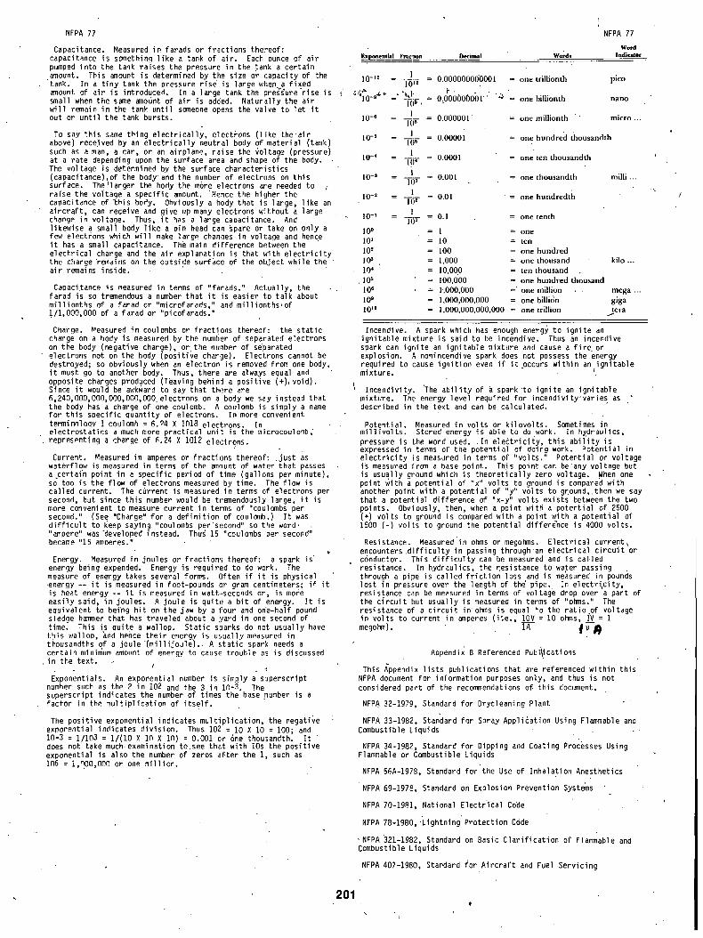
NFPA 77
Capacitance. Measured in farads or fractions the:-eof: capacitance is something like a tank of air. Each ounce of air pumped into the tank raises the pressure in the tank a certain amount. This amount is determined by the size or capacity of the tank. In a t iny tank the pressure rise is large when~a fi~ed amount of air is introduced. In a large tank the pressure rise is t small when the same amo6nt of air is added. Naturally the air will remain in the tank until someone opens the valve to let i t out or until the tank bursts.
To say this same thing electr ical ly, electrons (like the air above) received by an electr ical ly neutral body of material (tank) such as a man, a car, or an airplane, raise the ~o'Itage (pressure) at a rate depending upon the surface area and shape of the body. The voltage is determined by the'surface characteristics (capacitance) of the body • and the number of electrons on this surface. The larger the body the more electrons are needed to ,, raise the voltage a specific amount. ~Hence the higher the capacitance of ~his body. Ohviously a body that is large, like an aircraft, can receive and give up many electrons wCthout a large change in voltage. Thus, i t has a large capacitance. And likewise q small body like a pfn head can spare or take on only a few electrons which wil l make large chanaes in voltage and hence i t has a small capacitance. The main difference between the electrical charge and the air explanation is that with electr ic i ty the charge "ramains on the outside surface of the object while the airlremains inside.
Capacitance is measured in terms of "farads." Actually, the farad is so tremendous a number that i t is easier to talk about millionths of a farad or "microfarads," and millionths,of 1/1,000,000 of a farad or "picofarads."
Charge~ Measured in coulombs or fractions thereof•: the static charge on a body is measured by the number of separated electrons on the body (negative charge), or the n:nber of separated electrons not on the body (positiVe charge). Elecl.rons cannot be destroyed; so obviously when an electron is removed from one body, i t must go to another body. Thus, there are always equal and opposite charges produced (leaving behind a positive (+)!void). Since i t would be awkward to say that there are 6,240,000,O00,000,O00,O00. electrons on a body we say instead that the body has a charge of one coulomb. A coulomb i~ simply a name for this specific quantity of electrons. In more convenient terminnlooy I coulomb : 6.94 X 10¹⁸ electrons. In electrostatics a much more practical unit is the microcoulomb, representing a charge of ~.24 X 1012 electrons.
Current. Measured in amperes or fractions thereof: .just as waterflow is measured in terms of the amount of water that passes a certai~ point in a specific period of •time (gallc.ns per minute), so too is the flow of electrons measured by time. The flow is called current. The c~rrent is measured in terms c,f electrons per second, but since this number would be tramendously large, i t is more convenient to measure current in terms of "coulombs per second." (See "Charge" for a definition of coulomb.) I t was d i f f i cu l t to keep saying "coulumbs per'second" so the word, . "ampere" was Meveloped instead. Thus 15 "coulombs per second" became "15 amoeres."
Energy. Measured in joules or fractions thereof: a spark is" energy being expended. Energy is required to do w~rk. The measure of energy takes several forms. Often i f i t is physical energy -- i t is measured in foot-pounds or gram centimeters; i f i t is heat energy -- i t is measured in watt-seconds or, is more easily said, in joules. A joule is quite a bit of energy. I t is equivalent to befng hit on the jaw by a four and on•e-half pound sledge hammer that has traveled about a yard in one second of time. This is quite a wallop. Static sparks do n~t usually have this walloo, ~nd hence their energy is usually measured in thousandths of a joule (mi l l i joule). . A static spark needs a certain minimum amo,nt of energy to cause trouble as is discussed in the text.
Exponentials. An exponential number is simply a superscript number such as the 2 in 102 and the 3 in i~-3. The superscript indicates the number of times the base }~umber is a f a c to r in the m u l t i p l i c a t i o n of i t s e l f .
The pos i t i ve exponent ial ind icates m u l t i p l i c a t i o n , the negat ive exponent ial ind icates d i v i s i on . Thus 102 : I0 X 10 = 100; and 10-3 : 1/103 : I / ( I 0 X In X In) : 0.001 er ~ne thousandth. I t does not take much examination to.see theft wi th IOs the pos i t i ve exponent ia l i s a l s o the number of zeros ~ f te r the I , such as i~6 : i,~00,O~0 or one m i l l i o n .
Exponential Fraclion Decimal Words
NFPA 77
Word Indicator
10_~2 l = 10~---:-- ~- = 0 . 0 0 0 0 0 0 0 0 0 0 0 1 = o n e t r i l l i o n t h p i c o
" ,~O_g~- =~ "~1, = 0 . 0 0 0 0 0 0 0 0 1 " ~:~ o n e b i l l i o n t h n a n o ~ i r , .
l O - S
IO-S
10-4
lO-a
10-2
10-1
I 0 o 10 '
10 2 l O s .
1 0 '
, lO s 10 e 109 10~2
I - 0 . 0 0 0 0 0 1 " = o n e m i l l i o n t h " m i c r o . . . I ( P
I - 0 . 0 0 0 0 1 = o n e h u n d r e d t h o u s a n d t h I ( P
1 = - - = 0 . 0 0 0 1 = o n e t e n t h o u s a n d t h 10 4
1 . . . . 0 . 0 0 1 = o n e t h o u s a n d t h mi l l i . . .
l o s
= 1 . _ = 0 . 0 1 ' = o n e h u n d r e d t h 102
1 = o n e t e n t h
I(P - 0 . 1
: l = one : 10 = t e n
= 100 = o n e h u n d r e d
= 1 , 0 0 0 = o n e t h o u s a n d
= 1 0 0 0 0 = t e n t h o u s a n d .
= 1 0 0 , 0 0 0 = o n e h u n d r e d t h o u s a n d
= 1" ,000,000 =" o n e m i l l i o n , .
= 1 , 0 0 0 , 0 0 0 , 0 0 0 = o n e bi l l idn = 1 , 0 0 0 , 0 0 0 , 0 0 0 , 0 0 0 = o n e tr i l l ion
k i l o . . .
mega ... g i g a ter~
201
Incendive. A spark which has enough energy to ignite an ignitable miRture is said to be incendive. Thus an incendive spark can ignite an ignitable mixture and cause a fire_ or explosion. A nonincendive spark does not possess the energy required to cause ignition even i f i t occurs within an ignitable mixture. (
Incendivity. The ab i l i ty of a spark•to ignite an ign4table mixture. The energy level required for incendivity'varies as described in the text and can be calculated.
Potential. Measured in volts or ki lovolts. Sometimes in mi l l ivol ts. Stored energy is able to do work. In h~draulics, pressure is the word used. I n electr ic i ty, this abi l i ty is expressed in terms of the potential of doing work. Potential in electr ic i ty is measured in terms of "volts." Potential or voltage is measured from a base point. This point can be'any voltage but is usually ground which is theoretically zero voltage. When one point with a potential of "x" volts to ground is compared with another point with a potential of "y" volts to g[ound,.then we say that a potential difference of "x-y" volts exists between the two points. Obviously, then, when a point with a potential of 2500 (+) volts to ground is compared with a point with a potential of 1500 (-) volts to ground the potential differCnce is 4000 volts.
Resistance. Measured'in ohms or megohms. E lec t r i ca l current~ encounters d i f f i c u l t y in passing th roughan e l e c t r i c a l c i r c u i t or conductor. This d i f f i c u l t y can be measured and is ca l led res is tance. In hydrau l ics , the ~dsistance to water passing through a pipe is ca l led f r i c t i o n loss and is measured in pounds l os t in pressure over the length of thC p i p e . In e l e c t r i , c i t y , res is tance can be measured in terms o f ' v o l t a g e drop over a part of the c i r c u i t but usua l ly is measured in terms of "ohms." The res is tance of a c i r c u i t inohms is equal to the r a t i o .of vo l tage in vo l t s to current in amperes ( iCe. , IOV = 10 ohms, I..~V = i megohm). ~ ~ ,
Appendix B Referenced Publications
This Appendix l ists publications that are referenced within this NFPA document for information purposes only, and thus is not considered part of the recommendations o~ this document.
NFPA 32-1979, Standard for Drycleaning Plant
NFPA 33-1982, Standard for Spray Application Using Flammable and Combustible Liquids
NFPA 34-1982, Standard for Dipping and Coating Processes Using Flammable or Combustible Liquids
NFPA 56A-1978, Standard for the Use of Inhalation Anesthetics
NFPA 69-197e, Standard on Explosion Prevention Systems
NFPA 70-1981, National Electr'ical Code
NFPA 78-1980,'LightningProtection Code
• NFPA321-1982, Standard on Basic Clarification of Flammable and Combustible Liquids
NFPA 407-1980, Standard for Aircraft and Fuel Servicing
¢
\


![Committee Input No. 10-NFPA 77-2016 [ Chapter 17 ]](https://static.fdocuments.us/doc/165x107/617601f81243200a6f4599a6/committee-input-no-10-nfpa-77-2016-chapter-17-.jpg)