NFORMATION ON PRODUCTS FOR USERS
18
DOCUMENT document title/ titre du document NFORMATION ON PRODUCTS FOR USERS reference/réference ALOS-GSEG-EOPG-TN-07-0001 issue/édition 1 revision/révision 1 date of issue/date d’édition 5-Apr-2007 Document type/type de document Technical Note Hamburg PALSAR, PLR mode Acquired on 2006-10-05 a
Transcript of NFORMATION ON PRODUCTS FOR USERS
D O C U M E N T
document title/ titre du document
NFORMATION ON
PRODUCTS
FOR USERS
reference/réference
ALOS-GSEG-EOPG-TN-07-0001
issue/édition 1 revision/révision 1 date of issue/date d’édition 5-Apr-2007 Document type/type de document Technical Note
Hamburg PALSAR, PLR mode Acquired on 2006-10-05
a

Information on ALOS PALSAR products
for ADEN users issue 1 revision 1 - Error! Reference source not found.
page ii of iii
C H A N G E R E C O R D
Issue: 1 Revision: ERROR! REFERENCE SOURCE NOT FOUND.
reason for change/raison du changement page(s)/page(s) paragraph(s)/paragraph(s)
Corrected dependency of DN versus sigma nought in 8.1.
11 2
Information on ALOS PALSAR products
for ADEN users issue 1 revision 1 - Error! Reference source not found.
page iii of iii
T A B L E O F C O N T E N T S
1 INTRODUCTION ..................................................................................................1
2 REFERENCES .....................................................................................................2
3 ABBREVIATIONS AND ACRONYMS .................................................................2
4 PALSAR MODES.................................................................................................3
5 PRODUCT FORMAT SPECIFICATIONS.............................................................4
6 AVAILABLE PRODUCTS ....................................................................................4
7 GEOMETRIC CALIBRATION ..............................................................................8
8 RADIOMETRIC CALIBRATION.........................................................................11 8.1 General principles and assumptions ..................................................................................11 8.2 Sigma and gamma nought derivation for PALSAR 1.1 and 1.5 products ........................11
9 ALOS ORBIT......................................................................................................13
10 PALSAR OBSERVATION STRATEGY .............................................................13
11 RECOMMENDATIONS FOR THE SELECTION OF PALSAR MODES/PRODUCTS .........................................................................................14
11.1 ALOS Systematic Observation Strategy ...........................................................................14 11.2 Recommendation for the selection of PALSAR modes/products .....................................14
APPENDIX A PALSAR ANTENNA PATTERN FILE FORMAT................................................15

Information on ALOS PALSAR products
for ADEN users issue 1 revision 1 - Error! Reference source not found.
page 1 of 15
1 INTRODUCTION The Advanced Land Observing Satellite (ALOS), launched on 24 January 2005, is a joint project between JAXA and the Japan Resources Observation System Organization (JAROS). ALOS has three remote-sensing instruments: the Panchromatic Remote-sensing Instrument for Stereo Mapping (PRISM) for digital elevation mapping, the Advanced Visible and Near Infrared Radiometer type 2 (AVNIR-2) for precise land coverage observation, and the Phased Array type L-band Synthetic Aperture Radar (PALSAR) for day-and-night and all-weather land observation. Information on ALOS is available on the JAXA web site:
http://www.eorc.jaxa.jp/ALOS/about/about_index.htm PALSAR is an L-band SAR with an active antenna providing beam steering capabilities in elevation, with flexible viewing geometry:
The scope of this note is to provide summary information on PALSAR products to ADEN users. Information provided in this note is aligned with version I of PALSAR product format specifications. For any additional information, please contact ESA HelpDEsk at: [email protected]
Information on ALOS PALSAR products
for ADEN users issue 1 revision 1 - Error! Reference source not found.
page 2 of 15
2 REFERENCES
R-1 The ALOS PALSAR Observation strategy, A. Rosenqvist, M. Shimada, M. Watanabe, K. Yamauchi
R-2 ALOS PALSAR: Technical outline and mission concepts, A. Rosenqvist, M. Shimada, M.
Watanabe, 4th International Symposium on Retrieval of Bio-and Geophysical parameters from SAR Data for Land Applications, 16-19 November 2004, Austria
R-3 PALSAR Calibration and Validation, M. Shimada, M. Watanabe, A. Rosenqvist, T.
Tadono, IGARSS 2005 R-4 Calibration and Validation of PALSAR, M. Shimada, M. Watanabe, A. Rosenqvist, T.
Tadono, 2nd ALOS Cal/Val and Science Team Meeting, 8-9 Nov. 2004 R-5 ALOS PALSAR L1 Product format Specification version I,
http://www.eorc.jaxa.jp/ALOS/doc/format.htm R-6 ALOS home page, http://www.eorc.jaxa.jp/ALOS/index.htm
3 ABBREVIATIONS AND ACRONYMS This section controls the definition of all abbreviations and acronyms used within this document. Special attention has been paid to adopt abbreviations, acronyms and their definitions from international standards as ISO, ANSI or ECSS.
ADEN ALOS Data European Node ALOS Advanced Land Observing Satellite DSN PALSAR Fine Beam Single polarization mode FBS PALSAR Fine Beam Single polarization mode FBD PALSAR Fine Beam Single polarization mode JAXA Japan Aerospace Exploration Agency PALSAR Phased Array type L-band Synthetic Aperture Radar PLR PALSAR Polarimetric mode SAR Synthetic Aperture Radar WB1 PALSAR ScanSAR short bursts mode WB2 PALSAR ScanSAR long bursts mode
Information on ALOS PALSAR products
for ADEN users issue 1 revision 1 - Error! Reference source not found.
page 3 of 15
4 PALSAR MODES
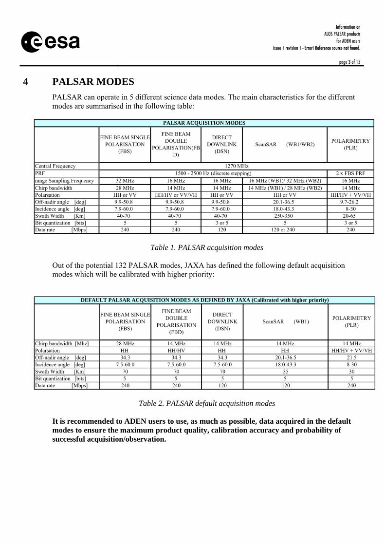
PALSAR can operate in 5 different science data modes. The main characteristics for the different modes are summarised in the following table:
Central FrequencyPRF 2 x FBS PRFrange Sampling Frequency 32 MHz 16 MHz 16 MHz 16 MHz (WB1)/ 32 MHz (WB2) 16 MHzChirp bandwidth 28 MHz 14 MHz 14 MHz 14 MHz (WB1) / 28 MHz (WB2) 14 MHzPolarsation HH or VV HH/HV or VV/VH HH or VV HH or VV HH/HV + VV/VHOff-nadir angle [deg] 9.9-50.8 9.9-50.8 9.9-50.8 20.1-36.5 9.7-26.2 Incidence angle [deg] 7.9-60.0 7.9-60.0 7.9-60.0 18.0-43.3 8-30Swath Width [Km] 40-70 40-70 40-70 250-350 20-65 Bit quantization [bits] 5 5 3 or 5 5 3 or 5Data rate [Mbps] 240 240 120 120 or 240 240
1500 - 2500 Hz (discrete stepping)
POLARIMETRY (PLR)
PALSAR ACQUISITION MODES
DIRECT DOWNLINK
(DSN)ScanSAR (WB1/WB2)
1270 MHz
FINE BEAM SINGLE POLARISATION
(FBS)
FINE BEAM DOUBLE
POLARISATION(FBD)
Table 1. PALSAR acquisition modes Out of the potential 132 PALSAR modes, JAXA has defined the following default acquisition modes which will be calibrated with higher priority:
Chirp bandwidth [Mhz] 28 MHz 14 MHz 14 MHz 14 MHz 14 MHzPolarsation HH HH/HV HH HH HH/HV + VV/VHOff-nadir angle [deg] 34.3 34.3 34.3 20.1-36.5 21.5Incidence angle [deg] 7.5-60.0 7.5-60.0 7.5-60.0 18.0-43.3 8-30Swath Width [Km] 70 70 70 35 30Bit quantization [bits] 5 5 5 5 5 Data rate [Mbps] 240 240 120 120 240
DIRECT DOWNLINK
(DSN)ScanSAR (WB1) POLARIMETRY
(PLR)
FINE BEAM SINGLE POLARISATION
(FBS)
FINE BEAM DOUBLE
POLARISATION (FBD)
DEFAULT PALSAR ACQUISITION MODES AS DEFINED BY JAXA (Calibrated with higher priority)
Table 2. PALSAR default acquisition modes It is recommended to ADEN users to use, as much as possible, data acquired in the default modes to ensure the maximum product quality, calibration accuracy and probability of successful acquisition/observation.
Information on ALOS PALSAR products
for ADEN users issue 1 revision 1 - Error! Reference source not found.
page 4 of 15
5 PRODUCT FORMAT SPECIFICATIONS
ALOS PALSAR products follow the standard CEOS format convention. The detailed product format specifications have been defined and are maintained by JAXA. Detailed information is available at: http://www.eorc.jaxa.jp/ALOS/doc/format.htm
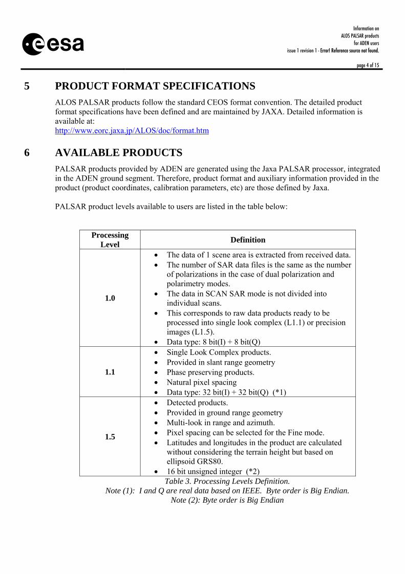
6 AVAILABLE PRODUCTS PALSAR products provided by ADEN are generated using the Jaxa PALSAR processor, integrated in the ADEN ground segment. Therefore, product format and auxiliary information provided in the product (product coordinates, calibration parameters, etc) are those defined by Jaxa. PALSAR product levels available to users are listed in the table below:
Processing Level Definition
1.0
• The data of 1 scene area is extracted from received data. • The number of SAR data files is the same as the number
of polarizations in the case of dual polarization and polarimetry modes.
• The data in SCAN SAR mode is not divided into individual scans.
• This corresponds to raw data products ready to be processed into single look complex (L1.1) or precision images (L1.5).
• Data type: 8 bit(I) + 8 bit(Q)
1.1
• Single Look Complex products. • Provided in slant range geometry • Phase preserving products. • Natural pixel spacing • Data type: 32 bit(I) + 32 bit(Q) (*1)
1.5
• Detected products. • Provided in ground range geometry • Multi-look in range and azimuth. • Pixel spacing can be selected for the Fine mode. • Latitudes and longitudes in the product are calculated
without considering the terrain height but based on ellipsoid GRS80.
• 16 bit unsigned integer (*2) Table 3. Processing Levels Definition.
Note (1): I and Q are real data based on IEEE. Byte order is Big Endian. Note (2): Byte order is Big Endian

Information on ALOS PALSAR products
for ADEN users issue 1 revision 1 - Error! Reference source not found.
page 5 of 15
The product levels available for each PALSAR acquisition mode are described in the following table:
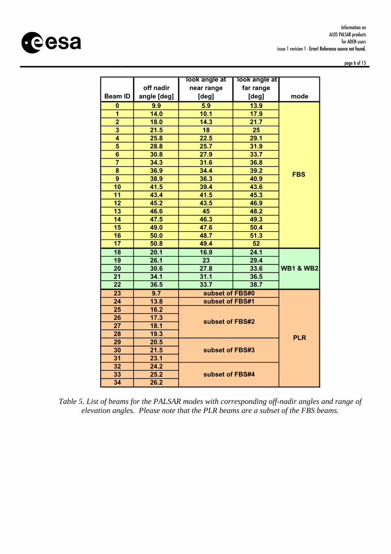
Table 4. Product Levels available per acquisition mode The complete list of possible off-nadir angles for the FB modes, ScanSAR and Polarimetry mode is provided in the following table:
Processing Level Observation Mode
1.0 1.1 1.5 Remarks
Single polarization (FBS)
√ √ √ 18 beams Fine mode
Dual polarization (FBD) √ √ √ 18 beams
Burst mode 1 (WB1) √ Not
available √ 3 scans 4 scans 5 scans (default) Scan SAR
mode Burst mode 2 (WB2) √ Not
available √ 3 scans 4 scans 5 scans ( default )
Direct Downlink mode (DN) √ √ √ 18 beams Polarimetry mode (PLR) √ √ √ 12 beams
Information on ALOS PALSAR products
for ADEN users issue 1 revision 1 - Error! Reference source not found.
page 6 of 15
Beam IDoff nadir
angle [deg]
look angle at near range
[deg]
look angle at far range
[deg] mode0 9.9 5.9 13.91 14.0 10.1 17.92 18.0 14.3 21.73 21.5 18 254 25.8 22.5 29.15 28.8 25.7 31.96 30.8 27.9 33.77 34.3 31.6 36.88 36.9 34.4 39.29 38.9 36.3 40.910 41.5 39.4 43.611 43.4 41.5 45.312 45.2 43.5 46.913 46.6 45 48.214 47.5 46.3 49.315 49.0 47.6 50.416 50.0 48.7 51.317 50.8 49.4 5218 20.1 16.9 24.119 26.1 23 29.420 30.6 27.8 33.621 34.1 31.1 36.522 36.5 33.7 38.723 9.724 13.825 16.226 17.327 18.128 19.329 20.530 21.531 23.132 24.233 25.234 26.2
subset of FBS#2
subset of FBS#3
subset of FBS#4
FBS
WB1 & WB2
PLR
subset of FBS#0subset of FBS#1
Table 5. List of beams for the PALSAR modes with corresponding off-nadir angles and range of elevation angles. Please note that the PLR beams are a subset of the FBS beams.

Information on ALOS PALSAR products
for ADEN users issue 1 revision 1 - Error! Reference source not found.
page 7 of 15
The table below provides the main characteristics for the products acquired in the default modes:
1 look rg & 2 looks az. 6.25 m x 6.25 m - - - -
1 look rg & 4 looks az. 12.5m x 12.5 m 12.5m x 12.5 m 12.5m x 12.5 m 12.5m x 12.5 m -
4 looks rg & 2 looks az. - - - - 100 m x 100 m
4.6 m rg 9.3 m rg 9.3 m rg 9.3 m rg
2.7 m to 4.5 m az 2.7 m to 4.5 m az 2.7 m to 4.5 m az 1.4 m to 2.3 m az
1 look rg & 4 look az.
~9.5 m rg x 10 m az [@o.n.a.34.3]
~ 19 m x 10 m az [@o.n.a. 34.3]
~ 19 m x 10 m az [@o.n.a. 34.3]
~30 m rg x 10 m az [@o.n.a. 21.5] -
4 looks rg & 2 looks az. - - - - ~71-157 m rg x 100 m az
[@5 scan, short burst]
1.1 1 look rg x 1 look az ~ 5m rg x ~ 4.5 m az ~ 10 m rg x ~ 4.5 m az ~ 10 m rg x ~ 4.5 m az ~ 10 m rg x ~ 4.5 m az -
Radiometric accuracy
Radiometric stability
1.0 57.0 sec [385 Km]1.1 Not Applicable1.5 350 Km
350 Km (5 scan)
300 Km (4 scan)250 Km (3 scan)
1.1 -1.51.11.5
Spatial resolution
FINE BEAM SINGLE POLARISATION
(FBS)
FINE BEAM DOUBLE
POLARISATION(FBD)
DIRECT DOWNLINK (DSN)
1.5
1.5
PRODUCT LEVEL
(az pixel spacing is PRF dependent, variable around the orbit)
PARAMETER
1 look rg x 1 look az
40 Km [o.n.a. 50.8 deg]
-
Absolute location accuracy
ProjectionGeoreferenced or Geocoded
< 1 pixel (actual measured value) [Note: Requirement: < 200 m ]
Slant Range (non-zero Doppler)
< 1 dB
< 1.5 dB1.5 -
Range scene size 1.5 -
16.4 sec [110 Km]
51-79 Km 62-83 Km
70 Km [o.n.a: 9.9 deg - 43.4 deg]
Azimuth Scene size
30 Km [o.n.a: 21.5 deg]50 Km [o.n.a: 45.2deg - 50.0 deg]
1.1 -
Pixel spacing
SCANSAR (WB1/WB2)
PROCESSING SETTINGS
POLARIMETRY (PLR)
Table 6. Main product requirements for the default PALSAR modes It should be noted that the values provided the table correspond to the quality requirements for PALSAR products or to the theoretical values (depending on the parameter).

Information on ALOS PALSAR products
for ADEN users issue 1 revision 1 - Error! Reference source not found.
page 8 of 15
7 GEOMETRIC CALIBRATION
In order to derive accurate geolocation information for standard PALSAR products, the following procedures are recommended. PALSAR L1.0 products The slant range distance to a given range sample ‘i’ can be estimated using one of the two equations below:
Eq. 1: ⎟⎟⎠
⎞⎜⎜⎝
⎛∆++⋅= t
PRFRank
ficSlrg
sampling2
Eq. 2: ⎟⎟⎠
⎞⎜⎜⎝
⎛++⋅+⋅= SWSTbiasSWSTPRIRank
ficSlrg
sampling2
PALSAR L1.1 products The slant range distance to a given range sample ‘i’ can be estimated for L1.1 products using the following equation:
Eq. 3: samplingf
icRSlrg ⋅+=20
Information on ALOS PALSAR products
for ADEN users issue 1 revision 1 - Error! Reference source not found.
page 9 of 15
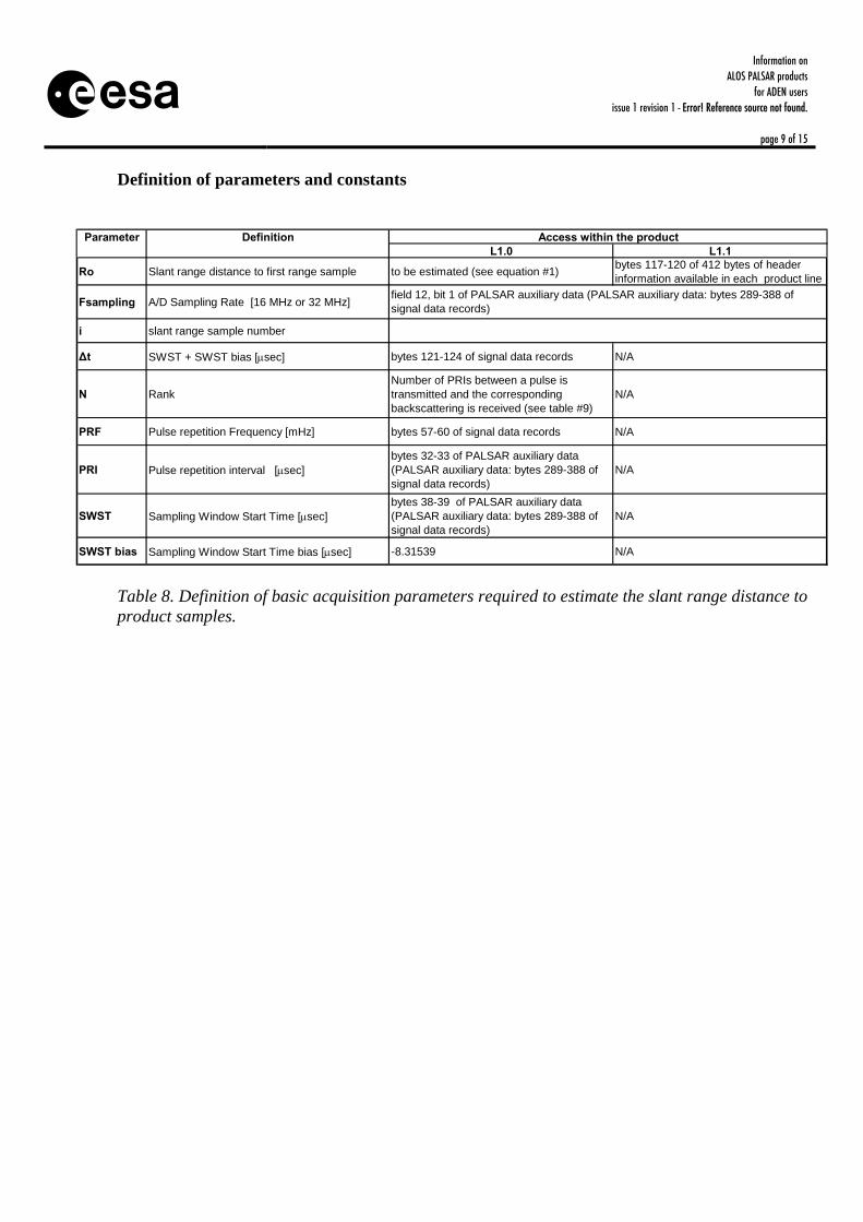
Definition of parameters and constants
L1.0 L1.1
Ro Slant range distance to first range sample to be estimated (see equation #1) bytes 117-120 of 412 bytes of header information available in each product line
Fsampling A/D Sampling Rate [16 MHz or 32 MHz]
i slant range sample number
∆t SWST + SWST bias [µsec] bytes 121-124 of signal data records N/A
N RankNumber of PRIs between a pulse is transmitted and the corresponding backscattering is received (see table #9)
N/A
PRF Pulse repetition Frequency [mHz] bytes 57-60 of signal data records N/A
PRI Pulse repetition interval [µsec]bytes 32-33 of PALSAR auxiliary data (PALSAR auxiliary data: bytes 289-388 of signal data records)
N/A
SWST Sampling Window Start Time [µsec]bytes 38-39 of PALSAR auxiliary data (PALSAR auxiliary data: bytes 289-388 of signal data records)
N/A
SWST bias Sampling Window Start Time bias [µsec] -8.31539 N/A
Parameter Definition Access within the product
field 12, bit 1 of PALSAR auxiliary data (PALSAR auxiliary data: bytes 289-388 of signal data records)
Table 8. Definition of basic acquisition parameters required to estimate the slant range distance to product samples.

Information on ALOS PALSAR products
for ADEN users issue 1 revision 1 - Error! Reference source not found.
page 10 of 15
MODEOFF-NADIR ANGLE
RANK
9.9 1014.0 1018.0 1121.5 925.8 1228.8 1130.8 1034.3 1236.9 1138.9 1041.5 1243.4 1145.2 1346.6 1247.5 1249.0 1350.0 1350.8 1320.1 826.1 1230.6 934.1 1236.5 119.7 18
13.8 1816.2 1817.3 1618.1 1519.3 1920.5 1821.5 1923.1 1824.2 1625.2 1626.2 20
FBS/FBD
WB1/WB2
PLR
Table 9. Definition of instrument rank per each off-nadir angle.
Information on ALOS PALSAR products
for ADEN users issue 1 revision 1 - Error! Reference source not found.
page 11 of 15
8 RADIOMETRIC CALIBRATION
Calibration of L1.1 and L1.5 PALSAR products is defined in the PALSAR product specifications, “Radiometric Data Record”, bytes 21-36. A summary is provided hereafter.
8.1 General principles and assumptions
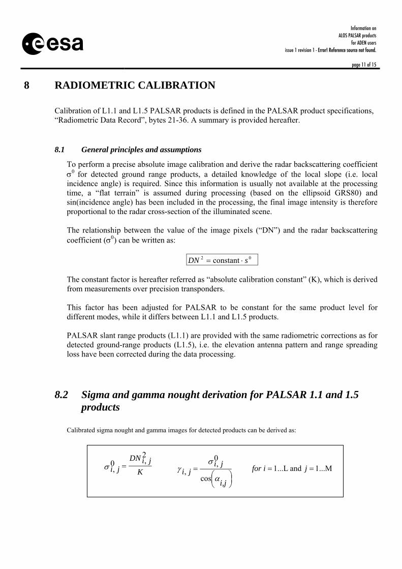
To perform a precise absolute image calibration and derive the radar backscattering coefficient σ0 for detected ground range products, a detailed knowledge of the local slope (i.e. local incidence angle) is required. Since this information is usually not available at the processing time, a “flat terrain” is assumed during processing (based on the ellipsoid GRS80) and sin(incidence angle) has been included in the processing, the final image intensity is therefore proportional to the radar cross-section of the illuminated scene. The relationship between the value of the image pixels (“DN”) and the radar backscattering coefficient (σ0) can be written as:
constant 02 sDN ⋅= The constant factor is hereafter referred as “absolute calibration constant” (K), which is derived from measurements over precision transponders. This factor has been adjusted for PALSAR to be constant for the same product level for different modes, while it differs between L1.1 and L1.5 products. PALSAR slant range products (L1.1) are provided with the same radiometric corrections as for detected ground-range products (L1.5), i.e. the elevation antenna pattern and range spreading loss have been corrected during the data processing.
8.2 Sigma and gamma nought derivation for PALSAR 1.1 and 1.5 products
Calibrated sigma nought and gamma images for detected products can be derived as:
K
DN jiji
2,0
, =σ ⎟⎠⎞⎜
⎝⎛
=
i,j
jiji
α
σγ
cos
0,
, 1...M and 1...L == jifor
Information on ALOS PALSAR products
for ADEN users issue 1 revision 1 - Error! Reference source not found.
page 12 of 15
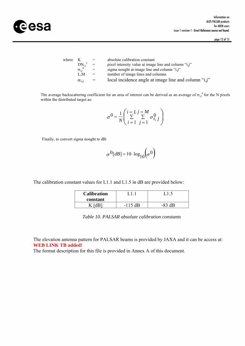
where K = absolute calibration constant DNi,j
2 = pixel intensity value at image line and column “i,j” σi,j
0 = sigma nought at image line and column “i,j” L,M = number of image lines and columns αi,j = local incidence angle at image line and column “i,j”
The average backscattering coefficient for an area of interest can be derived as an average of σi,j
0 for the N pixels within the distributed target as:
⎟⎠⎞
⎜⎝⎛
∑=
=∑=
==
Mj
jji
Li
iN 10,
1
10 σσ
Finally, to convert sigma nought to dB:
( )σσ 010log10][0 ⋅=dB
The calibration constant values for L1.1 and L1.5 in dB are provided below:
Calibration constant
L1.1 L1.5
K [dB] -115 dB -83 dB
Table 10. PALSAR absolute calibration constants The elevation antenna pattern for PALSAR beams is provided by JAXA and it can be access at: WEB LINK TB added! The format description for this file is provided in Annex A of this document.
Information on ALOS PALSAR products
for ADEN users issue 1 revision 1 - Error! Reference source not found.
page 13 of 15
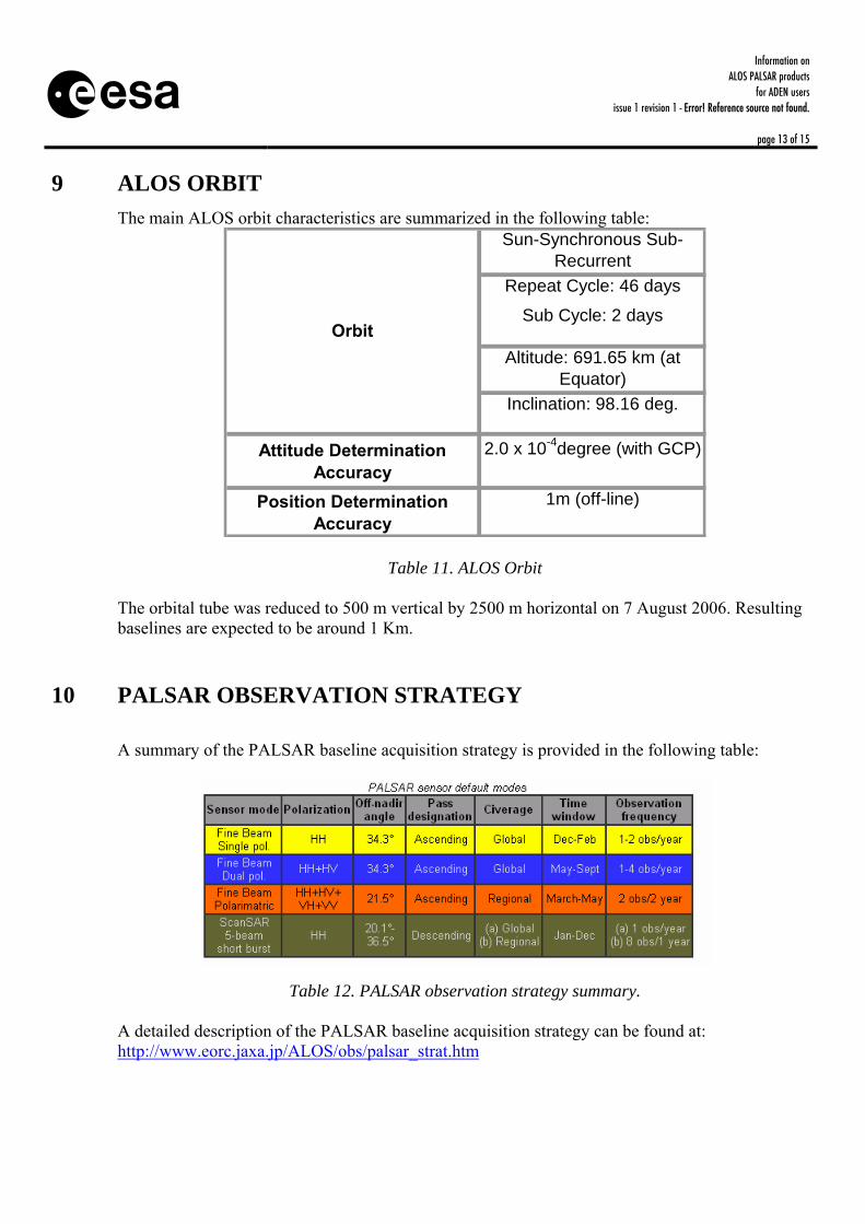
9 ALOS ORBIT
The main ALOS orbit characteristics are summarized in the following table: Sun-Synchronous Sub-
RecurrentRepeat Cycle: 46 days
Sub Cycle: 2 days
Altitude: 691.65 km (at Equator)
Inclination: 98.16 deg.
Attitude Determination Accuracy
2.0 x 10⁻⁴degree (with GCP)
Position Determination Accuracy
1m (off-line)
Orbit
Table 11. ALOS Orbit The orbital tube was reduced to 500 m vertical by 2500 m horizontal on 7 August 2006. Resulting baselines are expected to be around 1 Km.
10 PALSAR OBSERVATION STRATEGY A summary of the PALSAR baseline acquisition strategy is provided in the following table:
Table 12. PALSAR observation strategy summary. A detailed description of the PALSAR baseline acquisition strategy can be found at: http://www.eorc.jaxa.jp/ALOS/obs/palsar_strat.htm
Information on ALOS PALSAR products
for ADEN users issue 1 revision 1 - Error! Reference source not found.
page 14 of 15
11 RECOMMENDATIONS FOR THE SELECTION OF PALSAR
MODES/PRODUCTS
11.1 ALOS Systematic Observation Strategy The general user guidelines for requesting ALOS PALSAR products are provided by JAXA at: http://www.eorc.jaxa.jp/ALOS/obs/palsar_guide.htm
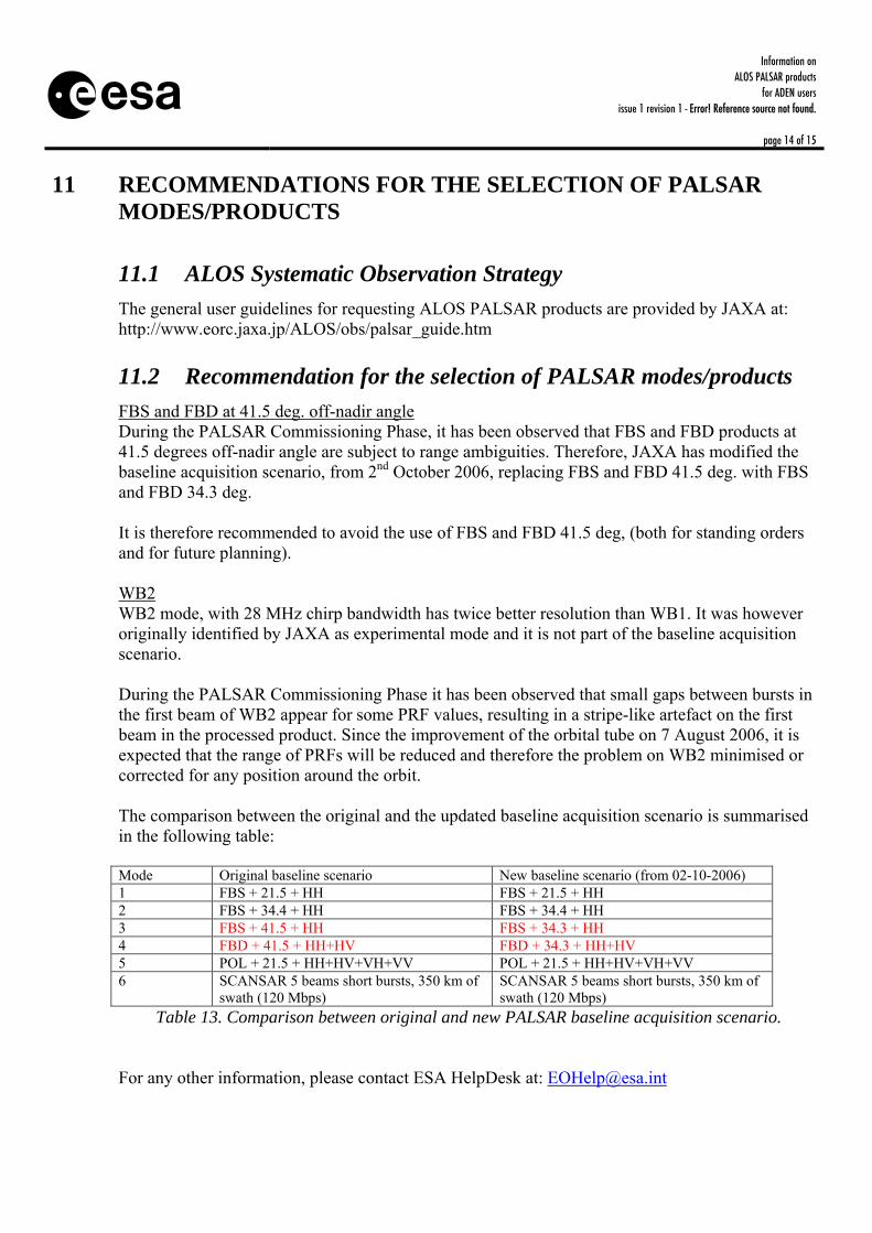
11.2 Recommendation for the selection of PALSAR modes/products FBS and FBD at 41.5 deg. off-nadir angle During the PALSAR Commissioning Phase, it has been observed that FBS and FBD products at 41.5 degrees off-nadir angle are subject to range ambiguities. Therefore, JAXA has modified the baseline acquisition scenario, from 2nd October 2006, replacing FBS and FBD 41.5 deg. with FBS and FBD 34.3 deg. It is therefore recommended to avoid the use of FBS and FBD 41.5 deg, (both for standing orders and for future planning). WB2 WB2 mode, with 28 MHz chirp bandwidth has twice better resolution than WB1. It was however originally identified by JAXA as experimental mode and it is not part of the baseline acquisition scenario. During the PALSAR Commissioning Phase it has been observed that small gaps between bursts in the first beam of WB2 appear for some PRF values, resulting in a stripe-like artefact on the first beam in the processed product. Since the improvement of the orbital tube on 7 August 2006, it is expected that the range of PRFs will be reduced and therefore the problem on WB2 minimised or corrected for any position around the orbit. The comparison between the original and the updated baseline acquisition scenario is summarised in the following table: Mode Original baseline scenario New baseline scenario (from 02-10-2006) 1 FBS + 21.5 + HH FBS + 21.5 + HH 2 FBS + 34.4 + HH FBS + 34.4 + HH 3 FBS + 41.5 + HH FBS + 34.3 + HH 4 FBD + 41.5 + HH+HV FBD + 34.3 + HH+HV 5 POL + 21.5 + HH+HV+VH+VV POL + 21.5 + HH+HV+VH+VV 6 SCANSAR 5 beams short bursts, 350 km of
swath (120 Mbps) SCANSAR 5 beams short bursts, 350 km of swath (120 Mbps)
Table 13. Comparison between original and new PALSAR baseline acquisition scenario. For any other information, please contact ESA HelpDesk at: [email protected]
Information on ALOS PALSAR products
for ADEN users issue 1 revision 1 - Error! Reference source not found.
page 15 of 15
APPENDIX A PALSAR ANTENNA PATTERN FILE FORMAT Antenna pattern format description has been defined by JAXA (Masanobu Shimada) as follows: Type: text file. bn :beam number : 0 nn :number of the samples : 81 off-0 :off nadir angle at the firt bin of the data : 5.90 dth :off nadir anguler increment : 0.1 Ghh, Ghv, Gvh, Gvv: antenna peak gain for four polarizations, 33.80, 33.76, 33.45,33.41 Ona, angle, ghh, ghv, gvh, gvv: 5.90,41.70, -4.74, -4.79, -4.67, -4.72 here, ona:off nadir angle, angle is the angular value measured from the peak direction of the PALSAR antenna (this information is less valuable), ghh, ghv, gvh, gvv are the relative antenna pattern gains, normalized by the peak values. bn ranges from 0 to 22, first 0-17 covers the strip mode antenna pattern, and the last five (18-22) corresponds to the patterns of the ScanSAR mode. The actual antenna pattern file can be accessed at: WEB LINK