New approach for the design of an optical square pulse generator
15
New approach for the design of an optical square pulse generator Nam Quoc Ngo 1, * and Le Nguyen Binh 2 1 Photonics Research Centre, School of Electrical and Electronic Engineering, Nanyang Technological University, Block S2, Nanyang Avenue, Singapore 639798 2 Department of Electrical and Computer Systems Engineering, Monash University, Clayton, Victoria 3168, Australia *Corresponding author: [email protected] Received 23 August 2006; revised 4 December 2006; accepted 12 January 2007; posted 7 February 2007 (Doc. ID 74368); published 18 May 2007 What is believed to be a new approach for the design and analysis of a reconfigurable optical square pulse generator using the concept of temporal optical integration and the digital signal processing method is presented. The reconfigurable square pulse generator is synthesized using compact active semiconductor- based waveguide technology, and it consists simply of the cascade of a tunable microring resonator (or a tunable all-pole filter) and a tunable asymmetrical Mach–Zehnder interferometer (or a tunable all-zero filter). The reconfigurable generator can convert an input picosecond pulse (i.e., soliton or Gaussian pulse) into an optical square pulse. The pulse width of the generated square pulse can be adjusted by controlling the time delay of a variable delay element in the tunable all-zero filter. The reconfigurable generator can convert an input picosecond pulse train into return-to-zero (RZ) and non-return-to-zero (NRZ) signals with square pulse shapes. The repetition rates of the generated RZ and NRZ signals can be varied by adjusting the bit period of the input picosecond pulse train, the input pulse width, and the time delay of the variable delay element. The effect of the deviation of the parameter values on the generator perfor- mance is also studied. © 2007 Optical Society of America OCIS codes: 070.1170, 130.0130, 230.0230. 1. Introduction The next generation of high-speed optical networks will require ultrafast optical signal processing func- tions, which are, however, difficult to implement by traditional electronic techniques. In particular, the shaping of a temporal pulse profile to generate an optical square pulse is an important function in op- tical signal processing. Optical square pulses have various important applications: They can approxi- mate non-return-to-zero (NRZ) pulses and experience less nonlinearity in the transmission than conven- tional pulse shapes [1], and they can also be employed to perform optical gating [2], in all-optical switching in dense optical time-division multiplexing systems [3], to monitor optical system performance [4], and in orthogonal wavelength division multiplexing systems to enhance the performance of conventional dense wavelength division multiplexing (DWDM) systems [5]. However, it is difficult to generate optical square pulses directly using conventional semiconductor la- sers or fiber lasers. To overcome this difficulty, optical square pulses have been generated by using various filtering techniques, eliminating the need to use high- speed modulators or optical nonlinear processes. The most commonly used technique involves the use of linear filtering to control the amplitudes and phases of the frequency components of an input short pulse. These techniques include arrayed waveguide gratings [6], nonlinear fiber loop mirrors [7], wave- guide transversal filters [8], and fiber Bragg gratings [3,9]. In this paper we propose an alternative technique for the generation of optical square pulses by using the concept of temporal optical integration and the digital signal processing method. The square pulse generator is reconfigurable and is synthesized by using com- pact semiconductor-based waveguide technology, and it consists simply of the cascade of a tunable all-pole 0003-6935/07/173546-15$15.00/0 © 2007 Optical Society of America 3546 APPLIED OPTICS Vol. 46, No. 17 10 June 2007
Transcript of New approach for the design of an optical square pulse generator

New approach for the design of an optical square pulsegenerator
Nam Quoc Ngo1,* and Le Nguyen Binh2
1Photonics Research Centre, School of Electrical and Electronic Engineering, Nanyang Technological University,Block S2, Nanyang Avenue, Singapore 639798
2Department of Electrical and Computer Systems Engineering, Monash University, Clayton, Victoria 3168, Australia
*Corresponding author: [email protected]
Received 23 August 2006; revised 4 December 2006; accepted 12 January 2007;posted 7 February 2007 (Doc. ID 74368); published 18 May 2007
What is believed to be a new approach for the design and analysis of a reconfigurable optical square pulsegenerator using the concept of temporal optical integration and the digital signal processing method ispresented. The reconfigurable square pulse generator is synthesized using compact active semiconductor-based waveguide technology, and it consists simply of the cascade of a tunable microring resonator (or atunable all-pole filter) and a tunable asymmetrical Mach–Zehnder interferometer (or a tunable all-zerofilter). The reconfigurable generator can convert an input picosecond pulse (i.e., soliton or Gaussian pulse)into an optical square pulse. The pulse width of the generated square pulse can be adjusted by controllingthe time delay of a variable delay element in the tunable all-zero filter. The reconfigurable generator canconvert an input picosecond pulse train into return-to-zero (RZ) and non-return-to-zero (NRZ) signalswith square pulse shapes. The repetition rates of the generated RZ and NRZ signals can be varied byadjusting the bit period of the input picosecond pulse train, the input pulse width, and the time delay ofthe variable delay element. The effect of the deviation of the parameter values on the generator perfor-mance is also studied. © 2007 Optical Society of America
OCIS codes: 070.1170, 130.0130, 230.0230.
1. Introduction
The next generation of high-speed optical networkswill require ultrafast optical signal processing func-tions, which are, however, difficult to implement bytraditional electronic techniques. In particular, theshaping of a temporal pulse profile to generate anoptical square pulse is an important function in op-tical signal processing. Optical square pulses havevarious important applications: They can approxi-mate non-return-to-zero (NRZ) pulses and experienceless nonlinearity in the transmission than conven-tional pulse shapes [1], and they can also be employedto perform optical gating [2], in all-optical switchingin dense optical time-division multiplexing systems[3], to monitor optical system performance [4], and inorthogonal wavelength division multiplexing systemsto enhance the performance of conventional dense
wavelength division multiplexing (DWDM) systems[5]. However, it is difficult to generate optical squarepulses directly using conventional semiconductor la-sers or fiber lasers. To overcome this difficulty, opticalsquare pulses have been generated by using variousfiltering techniques, eliminating the need to use high-speed modulators or optical nonlinear processes. Themost commonly used technique involves the use oflinear filtering to control the amplitudes and phasesof the frequency components of an input shortpulse. These techniques include arrayed waveguidegratings [6], nonlinear fiber loop mirrors [7], wave-guide transversal filters [8], and fiber Bragg gratings[3,9].
In this paper we propose an alternative techniquefor the generation of optical square pulses by using theconcept of temporal optical integration and the digitalsignal processing method. The square pulse generatoris reconfigurable and is synthesized by using com-pact semiconductor-based waveguide technology, andit consists simply of the cascade of a tunable all-pole
0003-6935/07/173546-15$15.00/0© 2007 Optical Society of America
3546 APPLIED OPTICS � Vol. 46, No. 17 � 10 June 2007

filter and a tunable all-zero filter. The reconfigurablegenerator can convert an input picosecond soliton (orGaussian) pulse from a mode-locked laser source intoan optical square pulse. The pulse width of the gener-ated square pulse can be changed by adjusting thetime delay of a variable delay element in the tunableall-zero filter. The generator can convert an input pi-cosecond pulse train into the RZ and NRZ signals withsquare pulse shapes. The repetition rates of the gen-erated RZ and NRZ signals can be adjusted by varyingthe bit period of the input picosecond pulse train, theinput pulse width, and the time delay of the variabledelay element in the tunable all-zero filter. Thus theproposed generator is reconfigurable and has sev-eral advantages over the methods described above.The proposed reconfigurable generator architecture ismuch simpler than that of the reconfigurable silica-based arrayed waveguide grating [6], where the latterconsists of, in this case, two arrayed waveguide grat-ings (AWGs), 32 variable optical attenuators, and 32tunable phase shifters (PSs) on the 32 delay lines con-necting the two AWGs. Although the duration of thesquare pulse generated by the nonlinear fiber loop mir-ror technique [7] can be varied by adjusting the dis-persion and length of the loop, different fiber sectionswith various lengths and various dispersion values arerequired to be spliced within the loop, and thus thetechnique is not truly reconfigurable. In addition, com-pared with the proposed reconfigurable compactwaveguide-based generator, which potentially can beintegrated with other devices on the same chip, thisnonlinear fiber loop mirror is complex, bulky, andcostly because two sources (i.e., a 1550 nm cw signaland a 1300 nm probe signal) and an erbium-dopedfiber amplifier (EDFA) are required [7]. The reconfigu-rable waveguide transversal filter [8] is more complexthan that of the proposed reconfigurable waveguidegenerator because the former consists of many opticaltaps (with each tap consisting of a tunable coupler anda tunable PS) on the delay lines (in this example, 32taps) as well as a bulky tunable fiber-optic frequencycomb generator, which consists of, for example, severalsegments of the dispersion shifted fibers. The squarepulse generator based on the fiber Bragg grating(FBG) is not truly reconfigurable because the pulsewidth and the repetition rate of the generated squarepulse depend on the parameters of the FBG (which arefixed during the fabrication stage) such as the depth ofthe refractive index, the phase profile, and the gratinglength [3,9]. This paper is organized as follows. Section2 reviews the theory of temporal optical integration,which is used to derive the theory of the proposedreconfigurable square pulse generator. Section 3 pre-sents the theory, design, and simulation results of thereconfigurable square pulse generator. The conclusionis given in Section 4. The square pulse generator is acoherent optical signal processor, which processes boththe amplitude and phase of an input optical signal.Thus the coherence time of the input optical signalmust be much larger than the sampling period T of thesquare pulse generator, and this requires the opticalsource to be coherent.
2. Theory of Optical Integrator
This section reviews the theory of a temporal opticalintegrator, which is used to derive the theory of theoptical square pulse generator, which is described inSection 3. We have recently proposed that a temporaloptical integrator is an analog optical signal proces-sor that performs the time integral of an input opticalsignal [10]. A temporal optical integrator approxi-mates the integral of a continuous-time input ampli-tude signal, x�t�, by sampling or processing the opticalsignal at the discrete time t � mT, where m is aninteger and T is the sampling period of the temporaloptical integrator; that is, the output amplitude pulseof the temporal optical integrator, y�t�, is given by
y�t�|t�mT ��0
mT
x�t�dt. (1)
The spectral response of an ideal temporal opticalintegrator is given by
Hideal��� ��1
j�T, 0 � �T��2�� � 1�2,
1j�2� � �T�
, 1�2 � �T��2�� � 1,(2)
where j � ��1 and � is the angular optical frequencyof the light wave. It is known that digital integratorshave been employed in electronic systems, which in-clude the design of compensators for control systems[11], and the measurement of the cardiac output ofthe heart [12]. Temporal optical integration, on theother hand, is still a new concept in the field of optics,especially in optical signal processing with many po-tential applications. We have recently shown that atemporal optical integrator can detect optical darksolitons and perform pulse shaping [10]. The tempo-ral optical integrator may be used as a basic buildingblock of many ultrafast all-optical signal processingsystems because the time integrals of signals maysometimes be required for further use or analysis.The temporal optical integrator may also be used forthe shaping of optical pulses (as shown in this paper)or potentially in an optical feedback control system.In this paper it is shown that the temporal opticalintegrator can convert an input soliton (or Gaussian)pulse into an optical steplike function, which is thenused for the generation of an optical square pulse.
The z-transform theory employed here can befound in Refs. 13 and 14. The z-transform amplitudetransfer function of a rectangular-type temporal op-tical integrator, HI�z�, is given by [10]
HI�z� �YI�z�X�z�
�1
1 � z�1, (3)
where z � exp�j�T� is the z-transform parameter,and z�1 represents one unit delay of T. In Eq. (3), X�z�
10 June 2007 � Vol. 46, No. 17 � APPLIED OPTICS 3547

is the z transform of an input amplitude pulse se-quence, x�n�, to the temporal optical integrator and isdefined as
X�z� � n���
�
x�n�z�n. (4)
Similarly, in Eq. (3), YI�z� is the z transform of anoutput amplitude pulse sequence, yI�n�, of the tempo-ral optical integrator and is defined as
YI�z� � n���
�
yI�n�z�n. (5)
In Eq. (3), HI�z� is the z transform of an amplitudeimpulse response, hI�n�, of the temporal optical inte-grator and is defined as
HI�z� � n���
�
hI�n�z�n. (6)
In Eq. (5), the output amplitude pulse sequence (orintegrated signal), yI�n�, of the temporal optical inte-grator is given by
yI�n� � x�n� � hI�n�, (7)
where � stands for the convolution operation.
3. Theory, Design, and Simulation Results of OpticalSquare Pulse Generator
Subsection 3.A presents the theory of the opticalsquare pulse generator. Subsection 3.B describes thedesign and implementation issues of the reconfigu-rable square pulse generator. Subsection 3.C pre-sents the simulation results of the reconfigurablesquare pulse generator.
A. Theory of Optical Square Pulse Generator
This section presents the theory of the optical squarepulse generator. An amplitude soliton pulse from amode-locked laser source is described by
x�n� � sech�n���, (8)
where 1.76� is the FWHM of the soliton pulse. Figure1(a) shows a soliton intensity pulse, |x�n�|2, where
Fig. 1. (a) Soliton intensity pulse, |x�n�|2, with FWHM � 17.6T. (b) Using Fig. 1(a) as an input signal, an optical step function, |yI�n�|2,is generated at the output of the temporal optical integrator. (c) Using Fig. 1(a) as an input signal, a delayed optical step function,|y2�n�|2 � |yI�n � D�|2, with D � 200, is generated at the output of the temporal optical integrator. (d) Plot of an optical square pulsewhich is described by |y�n�|2 � |yI�n�|2 � |y2�n�|2 � |yI�n�|2 � |yI�n � D�|2, where D � 200.
3548 APPLIED OPTICS � Vol. 46, No. 17 � 10 June 2007

the FWHM � 17.6T. Using x�n� in Eq. (8) as an inputto the temporal optical integrator as described byHI�z� in Eq. (3), Fig. 1(b) shows the plot of |yI�n�|2
[where yI�n� has been defined in Eq. (7)], which is theintegrated intensity signal at the output of the tem-poral optical integrator, and it looks like an opticalsteplike function. Figure 1(c) shows the plot of|y2�n�|2 � |yI�n � D�|2, where D � 200, which is adelayed integrated intensity signal at the output ofthe temporal optical integrator and is a delayed op-tical step function. Note that D �D 1� is an integerrepresenting the normalized delay, that is, D actuallymeans DT. Figure 1(d) shows the plot of |y�n�|2
� |yI�n�|2 � |y2�n�|2 � |yI�n�|2 � |yI�n � D�|2,which is an optical square pulse.
Using the results shown in Fig. 1, we now derivethe transfer function of the optical square pulse gen-
erator that can generate the optical square pulse asdescribed by y�n� in Fig. 1(d). Using the results shownin Fig. 1, Fig. 2(a) shows the signal-flow graph rep-resentation of the operating principle of the opticalsquare pulse generator in the discrete-time domain,where the notations of the variables used are consis-tent with those used in Eqs. (3)–(7). From Fig. 2(a), theoutput amplitude pulse sequence (or square pulse),y�n�, of the square pulse generator is given by
y�n� � yI�n� � y2�n� � yI�n� � yI�n � D�. (9)
Figure 2(b) shows the signal-flow graph represen-tation of the operating principle of the optical squarepulse generator in the z-transform domain, where thenotations of the variables used are consistent withthose used in Eqs. (3)–(7). Figure 2(b) is basically the
Fig. 2. (a) Signal-flow graph representation of the operating principle of the optical square pulse generator in the discrete-time domain.(b) Signal-flow graph representation of the operating principle of the optical square pulse generator in the z transform domain.
10 June 2007 � Vol. 46, No. 17 � APPLIED OPTICS 3549
z transform of Fig. 2(a). From Fig. 2(b), the z trans-form of the output amplitude pulse sequence (orsquare pulse), y�n�, of the optical square pulse gen-erator is given by
Y�z� � YI�z� � Y2�z� � YI�z� � z�DYI�z�� �1 � z�D�YI�z�. (10)
Substituting YI�z� � X�z�HI�z� and HI�z� from Eq. (3)into Eq. (10) gives
Y�z� � �1 � z�D�X�z�HI�z�
� �1 � z�D�X�z�1
1 � z�1. (11)
From Eq. (11), the z-transform amplitude transferfunction of the optical square pulse generator, H�z�, isthus given by
H�z� �Y�z�X�z�
�1 � z�D
1 � z�1 , (12)
which has D zeros periodically spaced on the unitcircle in the z plane, and they are located at z �exp�j2�k�D�, k � 0, 1, 2, . . . , D � 1. Note in Eq. (12)that the pole at z � 1 is actually canceled by a zero atz � 1 (with k � 0). Thus the optical square pulsegenerator is effectively an all-zero optical filter [or afinite impulse response (FIR) optical filter] and isalways stable.
B. Design of the Optical Square Pulse Generator
This section presents the design and implemen-tation issues of the reconfigurable square pulsegenerator, as described by H�z� in Eq. (12), usingcompact semiconductor-based waveguide technology.The square pulse generator [see Subsection 3.B.3 be-low) simply consists of the cascade of a tunable all-polefilter or a tunable microring resonator (see Subsection3.B.1 below) and a tunable all-zero filter or a tunableasymmetrical Mach–Zehnder interferometer (see Sub-section 3.B.2 below).
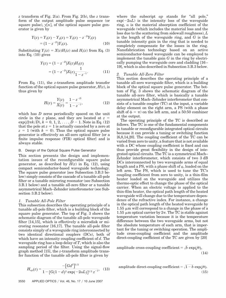
1. Tunable All-Pole FilterThis subsection describes the operating principle of atunable all-pole filter, which is a building block of thesquare pulse generator. The top of Fig. 3 shows theschematic diagram of the tunable all-pole waveguidefilter [14,15], which is effectively a microdisk or mi-croring resonator [16,17]. The tunable all-pole filterconsists simply of a waveguide ring interconnected bytwo identical directional couplers (DCs), both ofwhich have an intensity coupling coefficient of d. Thewaveguide ring has a loop delay of T, which is also thesampling period of the filter. Using the signal-flowgraph method [15], the z-transform amplitude trans-fer function of the tunable all-pole filter is given by
Hap�z� ���Gd2�1�2
1 � �G�1 � d�2 exp��2L��1�2 z�1, (13)
where the subscript ap stands for “all pole,”exp(�2�L) is the intensity loss of the waveguidering, � is the material absorption coefficient of thewaveguide (which includes the material loss and theloss due to the scattering from sidewall roughness), Lis the length of the waveguide ring, and G is thetunable intensity gain in the ring that is needed tocompletely compensate for the losses in the ring.Nanofabrication technology based on an activesemiconductor-based waveguide can be employed toimplement the tunable gain G in the ring by electri-cally pumping the waveguide core and cladding [16–19], which is also described in Subsection 3.B.3 below.
2. Tunable All-Zero FilterThis section describes the operating principle of atunable all-zero waveguide filter, which is a buildingblock of the optical square pulse generator. The bot-tom of Fig. 3 shows the schematic diagram of thetunable all-zero filter, which is basically a tunableasymmetrical Mach–Zehnder interferometer that con-sists of a tunable coupler (TC) at the input, a variabledelay element on the right arm, a PS (with a phaseshift of � � �) on the left arm, and a 50:50 combinerat the output.
The operating principle of the TC is described asfollows. The TC is one of the fundamental componentsin tunable or reconfigurable integrated optical circuitsbecause it can provide a tuning or switching function[6,8,14,20]. The coupling coefficient of the TC can bevaried from zero to unity, a feature that is not availablewith a DC whose coupling coefficient is fixed and canthus provide great flexibility in the design of inte-grated optical circuits. The TC is a symmetrical Mach–Zehnder interferometer, which consists of two 3 dBDCs interconnected by two waveguide arms of equallength and a PS, with a phase shift of �, loaded on theleft arm. The PS, which is used to tune the TC’scoupling coefficient from zero to unity, is a thin-filmheater loaded on the waveguide and utilizes thethermo-optic effect to change the phase of the opticalcarrier. When an electric voltage is applied to thethin-film heater, the optical path length of the heatedwaveguide will change due to the temperature depen-dence of the refractive index. For instance, a changein the optical path length of the heated waveguide by1.55 �m will correspond to a change in the phase of a1.55 �m optical carrier by 2�. The TC is stable againsttemperature variation because it is the temperaturedifference between the two waveguide arms, but notthe absolute temperature of each arm, that is impor-tant for the tuning or switching operation. The ampli-tude cross-coupling coefficient and the amplitudedirect-coupling coefficient of the TC are given by [20]
amplitude cross-coupling coefficient � �b exp�j �,(14)
amplitude direct-coupling coefficient � �1 � b exp�j �.(15)
3550 APPLIED OPTICS � Vol. 46, No. 17 � 10 June 2007

Fig. 3. Schematic of the proposed reconfigurable optical square pulse generator based on the active semiconductor waveguide technologyconsisting of the cascade of a tunable all-pole filter (or a microring resonator) and a tunable all-zero filter (or an asymmetrical Mach–Zehnder interferometer).
10 June 2007 � Vol. 46, No. 17 � APPLIED OPTICS 3551

The intensity cross-coupling coefficient, b, of the TC isgiven by
b �12�1 � cos ��, (16)
which can be varied from zero to unity (i.e., 0 � b� 1) by tuning the phase shift, �, of the PS between0 and � (i.e., 0 � � � �). That is, the phase shift, �,required to achieve a particular b value is, from Eq.(16), given by
� � cos�1�2b � 1�, (17)
where 0 � � � � for 0 � b � 1. In Eqs. (14) and (15),the output phase, �, of the TC is given by
� tan�1 sin �
cos � � 1�, (18)
where ���2 � � ��2 for 0 � � � �.The operating principle of the tunable all-zero filter
is described as follows. The variable delay element onthe right arm is tunable to provide the required true-time delay such that DT �D � 1, 2, . . . ,� is the timedelay difference between the two arms with T beingthe loop delay of the waveguide ring of the tunableall-pole filter. It is preferable that the variable delayelement also be implemented using the semiconduc-tor waveguide technology so that the whole architec-ture of the square pulse generator is completelybased on the semiconductor waveguide technology inorder to make it compact and integrable with otherwaveguide devices on the same chip. One promisingapproach that can be used for the implementation ofthe waveguide-based variable delay element has re-cently been reported in Ref. 21, where a cascadedfour-stage all-pass filter based on the ring resonatorshas been shown to be able to provide a wide contin-uous tuning range of true-time delay from 0 to 2560ps with promising results. Note that the variable de-lay element must be able to provide the true-timedelay over the operating bandwidth [or free spectralrange (FSR)] of the square pulse generator, that is,the group delay response of the variable delay devicemust be flat and have negligibly small group-delayripples over the FSR of the square pulse generator.Using the signal-flow graph method [15], the z-transform amplitude transfer function of the tunableall-zero filter is given simply by
Haz�z� � �1 � b � exp�j � � exp�j��
�1 ��b
�1 � b� Hd�z� � exp��j���, (19)
where the subscript az stands for “all zero,” and � isthe phase difference between the two waveguide
arms. Note that the PS with a phase shift � placed onthe left arm can also be loaded on the right armwithout changing the performance of the tunable all-zero filter because it is the phase difference (in thiscase � � �) between the two interferometer armsthat is important for correct operation. For ease offabrication, it may perhaps be better to incorporatethe PS on the left arm because the right arm alreadyhas the variable delay element. The z-transform am-plitude transfer function of the variable delay ele-ment, Hd�z�, is given by
Hd�z� � exp��DL� � z�D, D � 1, 2, . . . , (20)
where DL is the differential length between the twoarms (i.e., the length of the right arm is longer thanthat of the left arm by DL), z�D represents DT timedelay difference between the two arms (i.e., the timedelay of the right arm is larger than that of the leftarm by DT), and exp��DL� represents the insertionloss of the variable delay element. Putting Eq. (20)and � � � into Eq. (19) results in
Haz�z� � �1 � b�1�2 � exp�j� � ���
� 1 � �b exp��2DL�1 � b 1�2
z�D�. (21)
The operating principle of the tunable all-zero filteris summarized as follows. The PS in the TC is used toadjust the coupling coefficient of the TC to a desiredvalue so that the left arm and the right arm of theinterferometer will have the same transmission fac-tor (or loss). That is, the split signal (at the left outputof the TC) reaching the end of the left arm and thesplit signal (at the right output of the TC) reachingthe end of the right arm will both have the sameamplitude before they are combined by the 50:50combiner, and this requirement is described by Eq.(24) or Eq. (26) below. In addition, the use of the TC(instead of a DC with a fixed coupling coefficient) isimportant here to enable the square pulse generatorto be tuned so that the pulse width of the generatedsquare pulse can be adjusted (see the simulation re-sults in Subsection 3.C below). The reason is that asthe group delay of the variable delay element is ad-justed to achieve the required DT time delay differ-ence between the two arms, the insertion loss factorexp��DL� also changes [according to Eq. (20)], andhence the transmission factor or loss of the right armwill also change.3. Optical Square Pulse GeneratorIn this subsection, we describe the operating principleand the design and implementation issues of the re-configurable square pulse generator.
The operating principle of the reconfigurable squarepulse generator is described as follows. Figure 3 showsthe shape of the input pulse at different parts of thesquare pulse generator. When the loop gain G exactlybalances the losses in the ring [i.e., the closed-loop gain
3552 APPLIED OPTICS � Vol. 46, No. 17 � 10 June 2007

is equal to unity as described by Eq. (23) below], thetunable all-pole filter will function as a temporal inte-grator and will perform temporal integration of theinput pulse. That is, the output pulse increases in am-plitude until a time where the amplitude of the inputpulse drops to zero, and beyond this time the ampli-tude of the output pulse will remain at a maximumconstant value as expected from the integral function,and the shape of the output pulse will then look like asteplike pulse. It is important that the loop gain Gcompletely compensates for the losses in the ring; oth-erwise the amplitude of the output pulse will not in-crease to a maximum constant value but will insteadincrease to a maximum constant value for some timeand will then decrease with time (see the simulationresults in Subsection 3.C below). This step pulse willthen go into one input of the TC (whose function hasbeen described above) of the tunable all-zero filter. TheTC distributes the step pulse to the left arm and to theright arm of the interferometer according to its split-ting ratio, and the shapes of the pulses on the two armsare maintained as step pulses (as shown in Fig. 3). Themain function of the interferometer is to phase shift(using a PS) the step pulse by 180° in the left arm (togive an inverted step pulse) and to delay (using a vari-able delay element) the step pulse by a time delay ofDT in the right arm and then combine (using the 50:50combiner) these two pulses together at the end of thetwo arms to result in an inverted square pulse (in fieldamplitude) or a square pulse (in intensity) with a pulsewidth of just less than DT at the output of the tunableall-zero filter. Thus the pulse width of the generatedsquare pulse can be varied by adjusting the time delayDT of the variable delay element.
The design and implementation issues of the recon-figurable square pulse generator are described as fol-lows. When the tunable all-pole filter, as described byHap�z� in Eq. (13), is cascaded with the tunable all-zero filter, as described by Haz�z� in Eq. (21), the re-sulting z-transform amplitude transfer function ofthe reconfigurable square pulse generator is given by
H�z� � Hap�z� � Haz�z�� ��Gd2�1 � b��1�2 � exp�j� � ���
� � 1 � �b exp��2DL�1 � b 1�2
z�D
1 � �G�1 � d�2 exp��2L�1�2z�1��. (22)
The design of the square pulse generator requiresH�z� in Eq. (12) to be equal to H�z� in Eq. (22), that is,H�z� � H�z�, from which the following equations areobtained:
�G�1 � d�2 exp��2L��1�2 � 1, (23)
�b exp��2DL�1 � b 1�2
� 1. (24)
From Eq. (23), the required intensity gain, G, in thering of the tunable all-pole filter is given by
G �1
�1 � d�2 exp��2L�. (25)
In Eq. (25), the gain G decreases with a decrease ind, and it is thus desirable to use a small value of d(e.g., d � 0.03 can be easily implemented [16–19]) tominimize the electrical pump power required to givea large gain value. Thus for certain values of �, L, andd, the gain G must be tuned (by varying the currentinjection level) to provide the required gain value Gaccording to Eq. (25). From Eq. (24), the requiredintensity coupling coefficient of the TC in the tunableall-zero filter, b, is given by
b �1
1 � exp��2DL�. (26)
The variable delay element in the tunable all-zerofilter can be adjusted to provide the required timedelay difference of DT or differential length of DLbetween the two interferometer arms. Thus for cer-tain values of �, L, and D in Eq. (26), the TC must betuned by adjusting the phase shift � [i.e., 0 � �� � according to Eq. (17)] to provide the requiredcoupling coefficient b �0 � b � 1 according to Eq. (16)].
From the denominator of Eqs. (22) and (23), thesquare pulse generator has one pole located exactlyon the unit circle in the z plane, and it is given by
zpole � �G�1 � d�2 exp��2L��1�2 � 1, (27)
and D � 1 poles at the origin. From the numerator ofEq. (22), the square pulse generator has D zeros pe-riodically spaced around the unit circle in the z planeand they are described by
zzero,k � �b exp��2DL�1 � b 1�2D
� exp�j2�k�D�,
k � 0, 1, 2, . . . , D � 1. (28)
Putting Eq. (24) into Eq. (28), the D zeros are peri-odically spaced and are located exactly on the unitycircle in the z plane (i.e., the magnitudes or absolutevalues of the D zeros are equal to unity), and they aredescribed by
�zzero,k� � �b exp��2DL�1 � b 1�2D
� �1�1�D � 1. (29)
Note from Eq. (29) that the zero |zzero,0| � 1 �k � 0�cancels out with the pole at zpole � 1 [see Eq. (27)], andthus the square pulse generator is an all-zero filterand is always stable. Comparing Eqs. (27) and (29),we have |zzero,k| � zpole � 1, which gives
10 June 2007 � Vol. 46, No. 17 � APPLIED OPTICS 3553

�b exp��2DL�1 � b 1�2D
� �G�1 � d�2 exp��2L��1�2 � 1.
(30)
Therefore it is important, in practice, that the condi-tion |zzero,k| � zpole � 1 or Eq. (30) be met to ensurethat the generator can generate high-quality squarepulses and is always stable. From Eq. (30), the TC inthe tunable all-zero filter needs to be tuned to providethe required coupling coefficient b according to
b ��G�1 � d�2 exp��2L��D
exp��2DL� � �G�1 � d�2 exp��2L��D . (31)
In summary, for certain values of d, �, L, the loopgain G of the tunable all-pole filter must be tuned tothe required value, which is determined by Eq. (25).In practice, if the gain G deviates from its theoreticalvalue [Eq. (25)], and for a particular value of D, Eq.(31) [instead of Eq. (26)] must be used to tune thecoupling coefficient b of the TC to the required valueaccording to Eq. (31) to achieve good performance ofthe generator. This is because if both G [Eq. (25)] andb [Eq. (26)] deviate from their theoretical values inpractice then the performance of the generator woulddeteriorate. Thus Eqs. (25) and (31) must be used inpractice to achieve high-quality performance of thegenerator.
C. Simulation Results of Optical Square Pulse Generator
We now simulate the performance of a realisticsquare pulse generator [as described by H�z� in Eq.(22)] using typical practical parameter values. Theeffect of the deviation of the gain G from its theoret-ical value on the performance of the square pulsegenerator is also studied. As described in Subsection3.B above, the square pulse generator can be imple-mented by using active semiconductor waveguidematerials fabricated by the nanofabrication technol-ogy [16–19].
The typical practical parameter values used inthe design are obtained from Refs. 16–19, and theyare given as follows. The material absorption co-efficient of the semiconductor-based waveguide �(which includes the material loss and the loss due tothe scattering from sidewall roughness) is typicallybetween 1.5 and 55 cm�1, and we thus use �5 cm�1 in the design. According to Eq. (25), it is pre-ferred that the coupling coefficient, d, of the two DCsof the tunable all-pole filter be as small as possible inorder to reduce the required gain G in the loop, andwe use d � 0.03 in the design, which is a typicalpractical value. The effective refractive index of thewaveguide is typically neff � 3.1 for an InGaAsP-InPmaterial system. The radius of the ring of the all-polefilter can practically be as small as r � 5 �m, whichgives the loop length L � 2�r � 10� �m �31.42 �m. The processing speed of the square pulsegenerator can be estimated as follows. The samplingspeed or FSR of the square pulse generator is given
by FSR � 1�T, where T � neffL�c � neff�2�r��c is theloop delay of the ring of the all-pole filter (see Fig. 3)and c is the speed of light in vacuum. Thus the sam-pling speed or FSR � c��2�r � neff� of the squarepulse generator can be increased by reducing the ringradius r of the all-pole filter, which can be achievedusing the nanofabrication technology that has beenemployed to construct very small-size ring structuresbased on strongly guiding waveguides [16–19]. Whenthe square pulse generator is implemented usingactive semiconductor waveguide materials (e.g.,InGaAsP-InP material system) fabricated by thenanofabrication technology (see, for example, Refs.16–19) the required gain in the ring, G, can be im-plemented by electrically pumping (i.e., by varyingthe current injection level) the waveguide core andthe cladding to provide the necessary gain required toovercome losses in the ring according to Eq. (25) forcertain values of d, a, and L. For example, an InP-based active vertically coupled microdisk resonatorhas an active gain region (or a quantum-well region)introduced inside the ring cavity [16]. The gain sec-tion inside the cavity was achieved by electricallypumping the waveguide core and the cladding to pro-vide sufficient gain to overcome the cavity losses, andthe microdisk resonator has a radius of r � 5 �m,which gives FSR � 3 THz (or �24 nm) in the1550 nm wavelength window. Thus the sampling pe-riod of the square pulse generator can be as small asT � 0.33 ps.
1. Performance of Square Pulse Generator with NoDeviation of Parameter ValuesWe study the performance of the square pulse gen-erator with parameter values that do not deviatefrom their theoretical values. Using the typical prac-tical parameter values (as given above) of �5 cm�1, L � 31.42 �m, and d � 0.03, the requiredgain (ideal value) in the ring of the all-pole filter isG � 1.0967 according to Eq. (25), and the requiredcoupling coefficients b (ideal value) of the TC of theall-zero filter for various D values are, from Eq. (31),b � 0.9586 for D � 100, b � 0.9981 for D � 200,b � 1.0 for D � 400, and b � 1.0 for D � 600. Itis found that b will remain constant at b � 1.0 forD 300.
Figure 4(a) shows an input intensity soliton pulse,|x�n�|2, where x�n� has been defined in Eq. (8). Usingx�n� in Eq. (8) with FWHM � 17.6T � 5.8 ps as aninput to the square pulse generator with G �1.0967, Figs. 4(b), 4(c), and 4(d) show the generatedintensity optical square pulses, |y�n�|2 [where y�n�has been defined in Eq. (9)], for D � 200, D � 400,and D � 600, respectively. It can be seen that thepulse width of the generated square pulse increaseswith the time delay difference DT (or differentiallength DL) of the variable delay element (see Fig. 3).Thus the coupling coefficient b of the TC must betuned to give the required values of [according to Eq.(31)] b � 0.9981 for D � 200 [for Fig. 4(b)], b � 1.0 forD � 400 [for Fig. 4(c)], and b � 1.0 for D � 600 [forFig. 4(d)]. It is found that the output pulse width of
3554 APPLIED OPTICS � Vol. 46, No. 17 � 10 June 2007

the generated square pulse, the time delay differenceDT of the tunable all-zero filter, and the input pulsewidth of the soliton (or Gaussian) pulse relate to eachother by
output pulse width � DT, (32a)
output pulse � 10 � input pulse width, (32b)
DT � 10 � input pulse width. (32c)
We now determine the effect of the pulse width ofthe input soliton (or Gaussian) pulse on the shape ofthe generated square pulse. Figure 5(a) shows twoinput intensity soliton pulses with FWHM � 8.8T� 2.9 ps (solid curve) and FWHM � 17.6T � 5.8 ps(dashed curve). Using the pulses shown in Fig. 5(a) asinput pulses to the square pulse generator with theparameter values of G � 1.0967 and b � 0.9981 forD � 200, Fig. 5(b) shows the corresponding generated
square pulses, where the solid curve corresponds tothe case of FWHM � 8.8T � 2.9 ps of the input pulse[the solid curve in Fig. 5(a)], and the dashed curvecorresponds to the case of FWHM � 17.6T � 5.8 ps ofthe input pulse [the dashed curve in Fig. 5(a)]. It canthus be concluded that the smaller the input pulsewidth, the squarer the generated square pulse withsharply rising and falling edges will be.
We now compare the shape of the generated squarepulse when the input pulses are soliton and Gaussianpulses. The amplitude of an input soliton pulse isgiven by Eq. (8). The amplitude of an input Gaussianpulse is given by
x�n� � exp��n2��2�2��, (33)
where 2� is the full width of the intensity pulse at the1�e points. Figure 6(a) shows the input soliton pulse(solid curve) and the input Gaussian pulse (dashed
Fig. 4. (Color online) (a) Soliton intensity pulse, |x�n�|2, with FWHM � 17.6T � 5.81 ps. (b) Using Fig. 4(a) as an input signal, an opticalsquare pulse, |y�n�|2, with D � 200, is generated at the output of the square pulse generator with typical ideal values of G � 1.0967 andb � 0.9981 for D � 200. (c) Using Fig. 4(a) as an input signal, an optical square pulse, |y�n�|2, with D � 400, is generated at the outputof the square pulse generator with typical ideal values of G � 1.0967 and b � 1.0 for D � 400. (d) Using Fig. 4(a) as an input signal, anoptical square pulse, |y�n�|2, with D � 600, is generated at the output of the square pulse generator with typical ideal values ofG � 1.0967 and b � 1.0 for D � 600.
10 June 2007 � Vol. 46, No. 17 � APPLIED OPTICS 3555

curve) to the square pulse generator with parametervalues of G � 1.0967 and b � 0.9586 for D � 100.Figure 6(b) shows the corresponding generatedsquare pulses where the solid curve corresponds tothe case of the input soliton pulse [the solid curve inFig. 6(a)], and the dashed curve corresponds to thecase of the input Gaussian pulse [the dashed curve inFig. 6(a)]. It can thus be concluded from Fig. 6(b) thatthe generated square pulse (the dashed curve) fromthe input Gaussian pulse is squarer than the gener-ated square pulse (the solid curve) from the inputsoliton pulse.
Figure 7(a) shows an input RZ soliton pulse trainto the square pulse generator with D � 100, wherethe bit sequence is [110110101], the pulse width isFWHM � 8.8T � 2.9 ps, and the bit period is Tb �200T � 66 ps. Figure 7(b) shows the generated RZsquare pulse train at the output of the square pulsegenerator using typical ideal parameter values ofG � 1.0967 and b � 0.9586 for D � 100. It can be seenthat the bit period, Tb, of the input RZ soliton signal isequal to the bit period of the generated RZ squaresignal. It has been found that, in order for thesquare pulse generator to generate a high-quality RZsquare signal (i.e., no overlapping occurs betweenneighboring pulses), when the input is a RZ soliton
(or Gaussian) signal, the bit periods, Tb, of both theinput RZ signal and the generated RZ square signalmust satisfy Tb 2DT. Thus the repetition rate,1�Tb, of the generated RZ square signal can be variedif both the bit period, Tb, of the input RZ signal andthe time delay difference, DT, of the variable delayelement in the tunable all-zero filter are adjustedaccording to Tb 2DT, where DT � 10 � input pulsewidth according to Eq. (32c). Thus the bit period ofthe input RZ signal relates to the input pulse widthby Tb 20 � input pulse width, which means that thebit rate, 1�Tb, of the generated RZ signal can be in-creased by reducing the input pulse width. Using theinput pulse width � FWHM � 8.8T � 2.9 ps, the bitrate of the generated RZ signal is 1�Tb � 17 Gbit�s.The generated RZ square signal consists of high-quality square pulses with very flat top sections andsharply rising and falling edges because the typicalideal parameter values of G � 1.0967 and b �0.9586 for D � 100 are used.
Figure 8(a) shows an input RZ soliton pulse train tothe square pulse generator with D � 100, where thebit sequence is [110110101], the pulse width isFWHM � 8.8T � 2.9 ps, and the bit period is Tb �100T � 33 ps. Figure 8(b) shows the generated NRZsquare pulse train using typical ideal parameter val-
Fig. 5. (a) Two input soliton intensity pulses, |x�n�|2, with FWHM � 8.8T � 2.9 ps (solid curve) and FWHM � 17.6T � 5.8 ps (dashedcurve). (b) Corresponding generated square pulses, |y�n�|2, where the solid curve corresponds to the case of FWHM � 8.8T � 2.9 ps ofthe input pulse [solid curve in 5(a)] and the dashed curve corresponds to the case of FWHM � 17.6T � 5.8 ps of the input pulse [dashedcurve in 5(a)]. The square pulse generator has parameter values of G � 1.0967 and b � 0.9981 for D � 200.
3556 APPLIED OPTICS � Vol. 46, No. 17 � 10 June 2007

ues of G � 1.0967 and b � 0.9586 for D � 100. Thebit period, Tb, of the input RZ soliton pulse train isequal to the bit period of the generated NRZ squaresignal. It has been found that, in order for the gen-erator to generate a high-quality NRZ square signal(i.e., no overlapping occurs between neighboringpulses), when the input is a soliton (or Gauss-ian) pulse train, the bit periods, Tb, of both the inputRZ pulse train and the generated NRZ square signalmust satisfy Tb � DT. Thus the repetition rate, 1�Tb,of the generated NRZ square signal can be varied ifboth the bit period, Tb, of the input soliton RZ signaland the time delay difference, DT, of the variabledelay element in the tunable all-zero filter are ad-justed according to Tb � DT, where DT � 10 � inputpulse width according to Eq. (32c). Thus the bit periodof the input pulse train relates to the input pulsewidth by Tb � 10 � input pulse width, which meansthat the bit rate, 1�Tb, of the generated NRZ squaresignal can be increased by reducing the input pulsewidth. Using the input pulse width � FWHM� 8.8T � 2.9 ps, the bit rate of the generated NRZsquare signal is 1�Tb � 34 Gbit�s. The generatedNRZ square signal consists of high-quality squarepulses with very flat top sections and sharply risingand falling edges because typical ideal parameter val-
ues of G � 1.0967 and b � 0.9586 for D � 100 areused.
2. Performance of the Square Pulse Generator withDeviation of Parameter ValuesWe now consider the effect of the deviation of the gainfrom its theoretical value of G on the performance ofthe square pulse generator. Let G* be the deviatedgain from its theoretical value of G � 1.0967 as de-termined from Eq. (25).
As described above, using Fig. 7(a) as an input RZsoliton signal, Fig. 7(b) shows the generated RZsquare signal at the output of the square pulse gen-erator with typical ideal parameter values of G* �G � 1.0967 and b � 0.9586 for D � 100. Here thegenerator has zpole � 1 [according to Eq. (27)] andzzero,k � 1 � exp�j2�k�100�, k � 0, 1, 2, . . . , 99 [ac-cording to Eq. (28)], where the pole at zpole � 1 iscanceled out with one zero at zzero,0 � 1 �k � 0�. Thusthe generator consists only of 99 zeros located exactlyon the unit circle in the z plane (i.e., |zzero,k| � 1,k � 1, 2, . . . , 99), and it is always stable because it isa finite-impulse response filter. Figure 7(c) shows thegenerated RZ square signal at the output of thesquare pulse generator with a deviated gain value ofG* � 0.999G � 1.0956, which results in the required
Fig. 6. (a) Input soliton pulse with FWHM � 8.8T � 2.9 ps (solid curve) and input Gaussian pulse with pulse width of 2� � 10T� 3.3 ps (dashed curve). (b) Generated square pulses at the output of the square pulse generator with D � 100 when the input is a solitonpulse (solid curve) and when the input is a Gaussian pulse (dashed curve). The square pulse generator has parameter values ofG � 1.0967 and b � 0.9586 for D � 100.
10 June 2007 � Vol. 46, No. 17 � APPLIED OPTICS 3557

b � 0.9544 according to Eq. (31) for D � 100. Here thegenerator has zpole � 0.9995 [Eq. (27)] and zzero,k� 0.9995 � exp�j2�k�100�, k � 0, 1, 2, . . . , 99 [Eq.(28)], where the pole at zpole � 0.9995 is canceled outwith one zero at zzero,0 � 0.9995 �k � 0�, and thus thegenerator is always stable because it has 99 zeroslocated near (but not exactly) on the unit circle (i.e.,|zzero,k| � 0.9995, k � 1, 2, . . . , 99). Unlike the veryflat top sections and sharply rising and falling edgesof the square pulses generated by the ideal generatoras shown in Fig. 7(b), Fig. 7(c) shows that the squarepulses do not have those flat top sections, and theintensities of the top sections decrease slightly withtime; however, the generated pulses are still close tosquare pulse shapes, and there is no overlapping ofneighboring pulses. The main reason for the nonflattop sections of the pulses is that the 99 zeros arenot equal to unity (i.e., |zzero,k| � 0.9995, k �1, 2, . . . , 99) and are deviated slightly (due to thedeviated gain value of G* � 0.999G � 1.0956) fromthe unit circle instead of being exactly on the unit
circle. Figure 7(d) shows the generated RZ squaresignal at the output of the square pulse generatorwith a larger deviated gain value of G* � 0.995G� 1.0912, which results in the required b � 0.9334for D � 100. Here the generator has zpole � 0.9975 andzzero,k � 0.9975 � exp�j2�k�100�, k � 0, 1, 2, . . . , 99,where the pole at zpole � 0.9975 is canceled out withone zero at zzero,0 � 0.9975 �k � 0�, and thus thegenerator is always stable because it consists of 99zeros located near (but not exactly) on the unit circle(i.e., |zzero,k| � 0.9975, k � 1, 2, . . . , 99). Note thatthe intensities of the top sections of the pulses shownin Fig. 7(d) decrease more rapidly than those shownin Fig. 7(c) because the former has a larger gaindeviation, which results in the zeros being fartheraway from the unit circle.
A similar conclusion drawn from the results pre-sented in Fig. 7 can be applied to the results shown inFig. 8 here. As described above, using Fig. 8(a) as aninput RZ soliton signal, Fig. 8(b) shows the generatedNRZ square signal at the output of the square pulse
Fig. 7. (a) Input RZ soliton pulse train to the square pulse generator with D � 100 where the bit sequence is [110110101], the pulse widthis FWHM � 8.8T � 2.9 ps, and the bit period is Tb � 200T � 66 ps. (b) Generated RZ square pulse train at the output of the square pulsegenerator with typical ideal parameter values of G � 1.0967 and b � 0.9586 for D 100. (c) Generated RZ square signal at the outputof the square pulse generator with a deviated gain value of G* � 0.999G � 1.0956 and the required b � 0.9544 for D � 100. (d) GeneratedRZ square signal at the output of the square pulse generator with a deviated gain value of G* � 0.995G � 1.0912 and the requiredb � 0.9334 for D � 100.
3558 APPLIED OPTICS � Vol. 46, No. 17 � 10 June 2007

generator with typical ideal parameter values ofG* � G � 1.0967 and b � 0.9586 for D � 100. Herethe generator has zpole � 1 and zzero,k � 1 �exp�j2�k�100�, k � 0, 1, 2, . . . , 99, where the pole atzpole � 1 is canceled out with one zero at zzero,0 � 1�k � 0�. Thus the generator consists of 99 zeros lo-cated exactly on the unit circle in the z plane (i.e.,|zzero,k| � 1, k � 1, 2, . . . , 99), and it is always stable.Compared with the very flat top sections of thesquare pulses generated by the ideal generator asshown in Fig. 8(b), Fig. 8(c) shows that the intensitiesof the square pulses decrease slightly with time be-cause the 99 zeros (i.e., |zzero,k| � 0.9995, k � 1,2, . . . , 99) are not exactly on the unit circle as aresult of the deviated gain G* � 0.999G � 1.0956,which results in the required b � 0.9544 for D �100. Figure 8(d) shows the generated NRZ squaresignal using a larger deviated gain G* � 0.995G� 1.0912, which results in the required b � 0.9334for D � 100. Here the generator has zpole � 0.9975and zzero,k � 0.9975 � exp�j2�k�100�, k � 0, 1,
2, . . . , 99, where the pole at zpole � 0.9975 is canceledout with one zero at zzero,0 � 0.9975 �k � 0�, and thusthe generator is always stable. The intensities of thetop sections of the pulses shown in Fig. 8(d) decreasemore rapidly than those shown in Fig. 8(c) becausethe former has a larger gain deviation, which resultsin the zeros being farther away from the unit circle.
The results presented in Figs. 7 and 8 can be sum-marized as follows. For certain values of �, L, and d,the required gain G described by Eq. (25) must beused in the design and implementation. Using thisrequired gain G and D, the coupling coefficient bdescribed by Eq. (31) must be used in the design andimplementation to ensure that there is no overlap-ping between neighboring pulses of the generated RZsquare signal (Fig. 7) and the generated NRZ squaresignal (Fig. 8). However, the gain G* should, in prac-tice, be controlled to be as close to its theoretical valueof G as possible in order to ensure that high-qualityRZ and NRZ square signals with flat top sections andsharply rising and falling edges are generated.
Fig. 8. (a) Input RZ soliton pulse train to the square pulse generator with D � 100, where the bit sequence is [110110101], the pulse widthis FWHM � 8.8T � 2.9 ps, and the bit period is Tb � 100T � 33 ps. (b) Generated NRZ square pulse train at the output of the square pulsegenerator with typical ideal parameter values of G � 1.0967 and b � 0.9586 for D � 100. (c) Generated NRZ square signal at the outputof the square pulse generator with a deviated gain G* � 0.999G � 1.0956 and the required b � 0.9544 for D � 100. (d) Generated NRZsquare signal at the output of the square pulse generator with a deviated gain G* � 0.995G � 1.0912 and the required b � 0.9334 forD � 100.
10 June 2007 � Vol. 46, No. 17 � APPLIED OPTICS 3559

4. Conclusion
We have presented a novel approach for the designand analysis of a reconfigurable optical square pulsegenerator by using the concept of temporal opticalintegration and the digital signal processing tech-nique. The reconfigurable square pulse generatorconsists simply of the cascade of a tunable all-polefilter and a tunable all-zero filter and can be synthe-sized using compact active semiconductor-basedwaveguide technology. The square pulse generatorcan convert a soliton (or Gaussian) pulse into a pico-second square pulse. The smaller the input pulsewidth, the squarer the square pulse will be. The pulsewidth of the generated square pulse can be varied byadjusting the time delay of the variable delay elementin the tunable all-zero filter. The generator can con-vert an input RZ soliton (or Gaussian) pulse train intothe RZ square signal and the NRZ square signal. Therepetition rates of the generated RZ and NRZ squaresignals can be varied by adjusting the bit period ofthe input RZ signal, the input pulse width, and thetime delay of the variable delay element. The gainvalue in the ring of the tunable all-pole filter should,in practice, be controlled to be as close to its theoret-ical value as possible so that high-quality squarepulses with flat top sections and sharply rising andfalling edges can be generated. The reconfigurablesquare pulse generator has a periodic frequency re-sponse that repeats itself at every FSR, and thus itcan be used to generate square pulses at multiplewavelength carriers for application in wavelength di-vision multiplexing systems. Although our discussionhas been focused on the square pulse generator de-signed using the active semiconductor-waveguidetechnology, the methods and the results are applica-ble to other optical systems such as those based onfree-space optics and fiber gratings.
The authors thank the reviewers for their construc-tive criticisms of the work and their useful sugges-tions for improving the manuscript.
References1. S. Kodama and S. Wabnitz, “Compensation of NRZ signal dis-
tortion by initial frequency shifting,” Electron. Lett. 31, 1761–1762 (1995).
2. T. Morioka, S. Kawanishi, H. Takara, and M. Saruwatari,“Multiple-output, 100 Gbits all-optical demultiplexer based onmultichannel four-wave mixing pumped by a linearly-chirpedsquare pulse,” Electron. Lett. 30, 1959–1960 (1994).
3. J. H. Lee, P. C. Teh, P. Petropoulos, M. Ibsen, and D. J. Rich-ardson, “All-optical modulation and demultiplexing systemswith significant timing jitter tolerance through incorporationof pulse-shaping fiber Bragg gratings,” IEEE Photon. Technol.Lett. 14, 203–205 (2002).
4. A. L. J. Teixeira, P. S. André, M. Lima, J. F. da Rocha, andJ. L. Pinto, “Asynchronous optical performance monitor tech-niques for DWDM optical networks,” in Proceedings of Fourth
International Conference on Transparent Optical Networks(ICTON, 2002), Vol. 1, pp. 1–5.
5. R. Llorente, J. H. Lee, P. J. Almeida, M. Ibsen, D. J. Richard-son, J. Marti, and F. Ramos, “Novel orthogonal wavelengthdivision multiplexing (OWDM) scheme: theory and experi-ment,” in Proceedings of Sixteenth Annual Meeting of IEEE(LEOS, 2003), Vol. 2, pp. 547–548.
6. K. Takiguchi, K. Okamoto, T. Kominato, H. Takahashi, and T.Shibata, “Flexible pulse waveform generation using silica-waveguide-based spectrum synthesis circuit,” Electron. Lett.40, 537–538 (2004).
7. D. U. Noske, N. Pandit, and J. R. Taylor, “Picosecond squarepulse generation using nonlinear fibre loop mirror,” Electron.Lett. 28, 908–909 (1992).
8. S. Osawa, N. Wada, K. Kitayama, and W. Chujo, “Arbitrarily-shaped optical pulse train synthesis using weight�phase-programmable 32-tapped delay line waveguide filter,”Electron. Lett. 37, 1356–1357 (2001).
9. S. Longhi, M. Marano, P. Laporta, and V. Pruneri, “Multipli-cation and reshaping of high-repetition-rate optical pulsetrains using highly dispersive fiber Bragg gratings,” IEEEPhoton. Technol. Lett. 12, 1498–1500 (2000).
10. N. Q. Ngo, “Optical integrator for optical dark soliton detectionand pulse shaping,” Appl. Opt. 45, 6785–6791 (2006).
11. G. F. Franklin, J. D. Powell, and M. L. Workman, DigitalControl of Dynamic Systems, 2nd ed. (Addison-Wesley, 1990).
12. W. J. Tompkins and J. G. Webster, eds., Design ofMicrocomputers-Based Medical Instrumentation (Prentice-Hall,1981), Chap. 3.
13. A. V. Oppenheim and R. W. Schafer, Discrete-Time SignalProcessing (Prentice-Hall, 1989).
14. C. K. Madsen and J. H. Zhao, Optical Filter Design and Anal-ysis: A Signal Processing Approach (Wiley, 1999).
15. N. Q. Ngo and L. N. Binh, “Novel realization of monotonicButterworth-type lowpass, highpass and bandpass optical fil-ters using phase-modulated fiber-optic interferometers andring resonators,” J. Lightwave Technol. 12, 827–841 (1994).
16. K. Djordev, S.-J. Choi, S.-J. Choi, and P. D. Dapkus, “Gaintrimming of the resonant characteristics in vertically coupledInP microdisk switches,” Appl. Phys. Lett. 80, 3467–3469(2002).
17. S. J. Choi, Z. Peng, Q. Yang, S. J. Choi, and P. D. Dapkus, “Aneight-channel demultiplexing switch array using verticallycoupled active semiconductor microdisk resonators,” IEEEPhoton. Technol. Lett. 16, 2517–2519 (2004).
18. K. Djordev, S.-J. Choi, S.-J. Choi, and P. D. Dapkus, “Activesemiconductor microdisk devices,” J. Lightwave Technol. 20,105–113 (2002).
19. K. Djordev, S.-J. Choi, S.-J. Choi, and P. D. Dapkus, “Study ofthe effects of the geometry on the performance of verticallycoupled InP microdisk resonators,” J. Lightwave Technol. 20,1485–1492 (2002).
20. N. Q. Ngo and L. N. Binh, “Synthesis of tunable opticalwaveguide filters using digital signal processing technique,” J.Lightwave Technol. 24, 3520–3531 (2006).
21. M. S. Rasras, C. K. Madsen, M. A. Cappuzzo, E. Chen, L. T.Gomez, E. J. Laskowski, A. Griffin, A. Wong-Foy, A. Gasparyan,A. Kasper, J. L. Grange, and S. S. Patel, “Integrated resonance-enhanced variable optical delay lines,” IEEE Photon. Technol.Lett. 17, 834–836 (2005).
3560 APPLIED OPTICS � Vol. 46, No. 17 � 10 June 2007