Network Technology 1 - DHBW Stuttgart
28
Transcript of Network Technology 1 - DHBW Stuttgart

Link Layer
“Taking turns” MAC protocols
channel partitioning MAC protocols: ▪ share channel efficiently and fairly at high load ▪ inefficient at low load: delay in channel access, 1/N
bandwidth allocated even if only 1 active node! random access MAC protocols ▪ efficient at low load: single node can fully utilize channel ▪ high load: collision overhead
“taking turns” protocols look for best of both worlds!

Link Layer
polling: ❖ master node “invites”
slave nodes to transmit in turn
❖ typically used with “dumb” slave devices
❖ concerns: ▪ polling overhead ▪ latency ▪ single point of failure
(master)
master
slaves
poll
data
data
“Taking turns” MAC protocols

Link Layer
token passing: ❖ control token passed from one
node to next sequentially. ❖ token message ❖ concerns:
▪ token overhead ▪ latency ▪ single point of failure (token)
T
data
(nothing to send)
T
“Taking turns” MAC protocols

cable headend
CMTS
ISP
cable modem termination system
❖ multiple 40Mbps downstream (broadcast) channels ▪ single CMTS transmits into channels
❖ multiple 30 Mbps upstream channels ▪ multiple access: all users contend for certain upstream channel time slots (others
assigned)
Cable access network
cable modemsplitter
…
…
Internet frames,TV channels, control transmitted downstream at different frequencies
upstream Internet frames, TV control, transmitted upstream at different frequencies in time slots

Link Layer
DOCSIS: data over cable service interface spec ❖ FDM over upstream, downstream frequency channels ❖ TDM upstream: some slots assigned, some have contention ▪ downstream MAP frame: assigns upstream slots ▪ request for upstream slots (and data) transmitted random access (binary backoff)
in selected slots
MAP frame for Interval [t1, t2]
Residences with cable modems
Downstream channel i
Upstream channel j
t1 t2
Assigned minislots containing cable modem upstream data frames
Minislots containing minislots request frames
cable headend
CMTS
Cable access network

Link Layer
Summary of MAC protocols
❖ channel partitioning, by time, frequency or code ▪ Time Division, Frequency Division
❖ random access (dynamic), ▪ ALOHA, S-ALOHA, CSMA, CSMA/CD ▪ carrier sensing: easy in some technologies (wire), hard in
others (wireless) ▪ CSMA/CD used in Ethernet ▪ CSMA/CA used in 802.11
❖ taking turns ▪ polling from central site, token passing ▪ bluetooth, FDDI, token ring
Link Layer
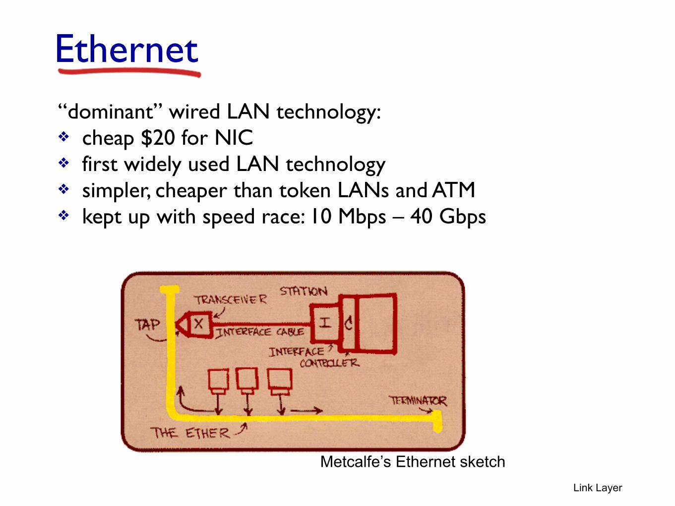
Ethernet“dominant” wired LAN technology: ❖ cheap $20 for NIC ❖ first widely used LAN technology ❖ simpler, cheaper than token LANs and ATM ❖ kept up with speed race: 10 Mbps – 40 Gbps
Metcalfe’s Ethernet sketch

Link Layer
Ethernet: physical topology❖ bus: popular through mid 90s ▪ all nodes in same collision domain (can collide with each
other) ❖ star: prevails today ▪ active switch in center ▪ each “spoke” runs a (separate) Ethernet protocol (nodes do
not collide with each other)
switch
bus: coaxial cablestar

Link Layer
Ethernet frame structure
sending adapter encapsulates IP datagram (or other network layer protocol packet) in Ethernet frame !!
!preamble: ❖ 7 bytes with pattern 10101010 followed by one byte
with pattern 10101011 ❖ used to synchronize receiver, sender clock rates
dest. address
source address data (payload) CRCpreamble
type

Link Layer
Ethernet frame structure (more)❖ addresses: 6 byte source, destination MAC addresses ▪ if adapter receives frame with matching destination address,
or with broadcast address (e.g. ARP packet), it passes data in frame to network layer protocol
▪ otherwise, adapter discards frame ❖ type: indicates higher layer protocol (mostly IP but others
possible, e.g., Novell IPX, AppleTalk) ❖ CRC: cyclic redundancy check at receiver ▪ error detected: frame is dropped
dest. address
source address
data (payload) CRCpreamble
type

Link Layer
Ethernet addressing

Link Layer
Ethernet: unreliable, connectionless
❖ connectionless: no handshaking between sending and receiving NICs
❖ unreliable: receiving NIC doesnt send acks or nacks to sending NIC ▪ data in dropped frames recovered only if initial sender
uses higher layer rdt (e.g., TCP), otherwise dropped data lost
❖ Ethernet’s MAC protocol: unslotted CSMA/CD with binary backoff

Link Layer
802.3 Ethernet standards: link & physical layers
❖ many different Ethernet standards ▪ common MAC protocol and frame format ▪ different speeds: 2 Mbps, 10 Mbps, 100 Mbps, 1Gbps, 10G
bps ▪ different physical layer media: fiber, cable
application transport network
link physical
MAC protocol and frame format
100BASE-TX
100BASE-T4
100BASE-FX100BASE-T2
100BASE-SX 100BASE-BX
fiber physical layercopper (twister pair) physical layer

Link Layer
Ethernet switch❖ link-layer device: takes an active role ▪ store, forward Ethernet frames ▪ examine incoming frame’s MAC address, selectively
forward frame to one-or-more outgoing links when frame is to be forwarded on segment, uses CSMA/CD to access segment
❖ transparent ▪ hosts are unaware of presence of switches
❖ plug-and-play, self-learning ▪ switches do not need to be configured

Link Layer
Switch: multiple simultaneous transmissions
❖ hosts have dedicated, direct connection to switch
❖ switches buffer packets ❖ Ethernet protocol used on each
incoming link, but no collisions; full duplex ▪ each link is its own collision
domain ❖ switching: A-to-A’ and B-to-B’ can
transmit simultaneously, without collisions
switch with six interfaces (1,2,3,4,5,6)
A
A’
B
B’ C
C’
1 2
345
6

Link Layer
Switch forwarding table
Q: how does switch know A’ reachable via interface 4, B’ reachable via interface 5?
switch with six interfaces (1,2,3,4,5,6)
A
A’
B
B’ C
C’
1 2
345
6❖ A: each switch has a switch table, each entry: ▪ (MAC address of host, interface to reach host,
time stamp) ▪ looks like a routing table!
Q: how are entries created, maintained in switch table?
▪ something like a routing protocol?
A
A’
B
B’ C
C’
1 2
345
6
Link Layer
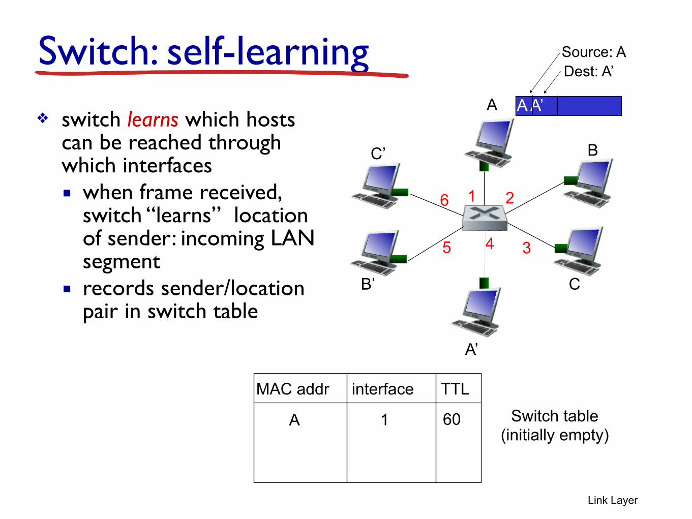
Switch: self-learning❖ switch learns which hosts
can be reached through which interfaces ▪ when frame received,
switch “learns” location of sender: incoming LAN segment
▪ records sender/location pair in switch table
A A’
Source: ADest: A’
MAC addr interface TTLSwitch table
(initially empty)A 1 60

Link Layer
Switch: frame filtering/forwarding
when frame received at switch:
1. record incoming link, MAC address of sending host 2. index switch table using MAC destination address 3. if entry found for destination
then { if destination on segment from which frame arrived
then drop frame else forward frame on interface indicated by entry } else flood /* forward on all interfaces except arriving interface */

A
A’
B
B’ C
C’
1 2
345
6
Link Layer
Self-learning, forwarding: exampleA A’
Source: ADest: A’
MAC addr interface TTLswitch table
(initially empty)A 1 60
A A’A A’A A’A A’A A’
❖ frame destination, A’, locaton unknown: flood
A’ A
❖ destination A location known:
A’ 4 60
selectively send on just one link

Link Layer
Interconnecting switches
❖ switches can be connected together
Q: sending from A to G - how does S1 know to forward frame destined to F via S4 and S3? ❖A: self learning! (works exactly the same as in single-switch case!)
A
B
S1
C D
E
FS2
S4
S3
H
I
G

Link Layer
Self-learning multi-switch exampleSuppose C sends frame to I, I responds to C
❖ Q: show switch tables and packet forwarding in S1, S2, S3, S4
A
B
S1
C D
E
FS2
S4
S3
H
I
G
Link Layer
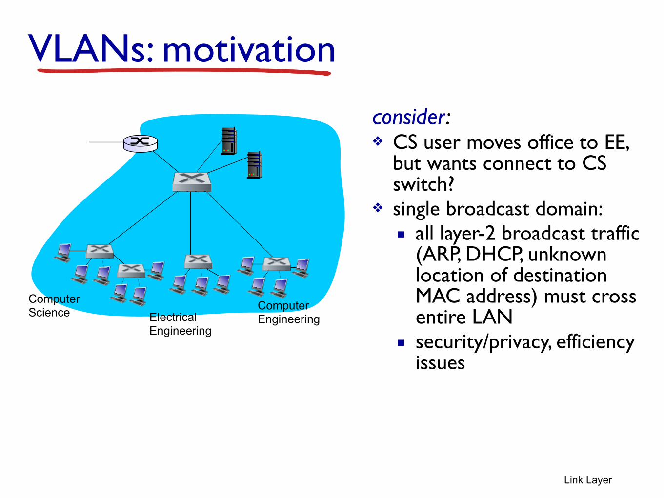
VLANs: motivation
consider: ❖ CS user moves office to EE,
but wants connect to CS switch?
❖ single broadcast domain: ▪ all layer-2 broadcast traffic
(ARP, DHCP, unknown location of destination MAC address) must cross entire LAN
▪ security/privacy, efficiency issues
Computer Science Electrical
Engineering
Computer Engineering
Link Layer
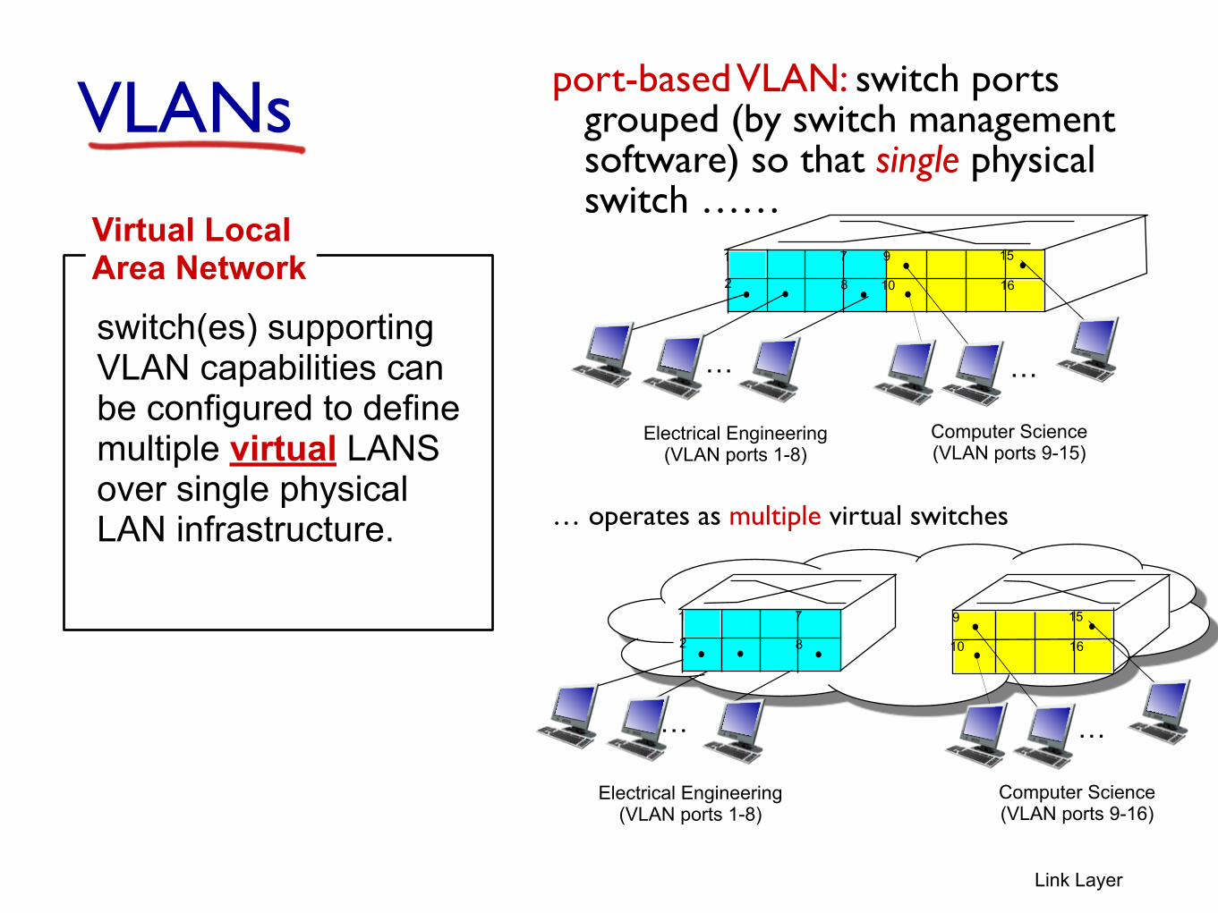
VLANs port-based VLAN: switch ports grouped (by switch management software) so that single physical switch ……
switch(es) supporting VLAN capabilities can be configured to define multiple virtual LANS over single physical LAN infrastructure.
Virtual Local Area Network 1
8
9
16102
7
…
Electrical Engineering (VLAN ports 1-8)
Computer Science (VLAN ports 9-15)
15
…
Electrical Engineering (VLAN ports 1-8)
…
1
82
7 9
1610
15
…
Computer Science (VLAN ports 9-16)
… operates as multiple virtual switches
Link Layer
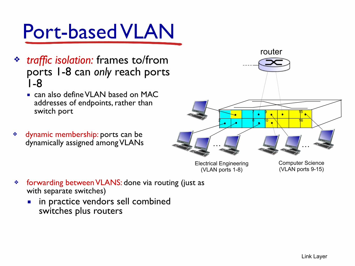
Port-based VLAN
1
8
9
16102
7
…
Electrical Engineering (VLAN ports 1-8)
Computer Science (VLAN ports 9-15)
15
…
❖ traffic isolation: frames to/from ports 1-8 can only reach ports 1-8 ▪ can also define VLAN based on MAC
addresses of endpoints, rather than switch port
❖ dynamic membership: ports can be dynamically assigned among VLANs
router
❖ forwarding between VLANS: done via routing (just as with separate switches) ▪ in practice vendors sell combined
switches plus routers

Link Layer
VLANS spanning multiple switches
❖ trunk port: carries frames between VLANS defined over multiple physical switches ▪ frames forwarded within VLAN between switches can’t be vanilla 802.1
frames (must carry VLAN ID info) ▪ 802.1q protocol adds/removed additional header fields for frames
forwarded between trunk ports
1
8
9
102
7
…
Electrical Engineering (VLAN ports 1-8)
Computer Science (VLAN ports 9-15)
15
…
2
73
Ports 2,3,5 belong to EE VLAN Ports 4,6,7,8 belong to CS VLAN
5
4 6 816
1

Link Layer
type
2-byte Tag Protocol Identifier (value: 81-00)
Tag Control Information (12 bit VLAN ID field, 3 bit priority field like IP TOS)
Recomputed CRC
802.1Q VLAN frame format
802.1 frame
802.1Q frame
dest. address
source address data (payload) CRCpreamble
data (payload) CRC
type

28
thank you. questions?