Network Layer (part 2) CPSC 363 Computer Networks Ellen Walker Hiram College (Includes figures from...
35
Network Layer (part 2) CPSC 363 Computer Networks Ellen Walker Hiram College (Includes figures from Computer Networking by Kurose & Ross, © Addison Wesley 2002)
-
Upload
shannon-copeland -
Category
Documents
-
view
225 -
download
0
Transcript of Network Layer (part 2) CPSC 363 Computer Networks Ellen Walker Hiram College (Includes figures from...
Network Layer (part 2)
CPSC 363 Computer Networks
Ellen Walker
Hiram College
(Includes figures from Computer Networking by Kurose & Ross, © Addison Wesley 2002)
Summary so far (4.5)
• Every router has a “next hop” table to route packets to the right interface (output)
• Routing algorithms determine these tables– Global– Distributed
• In the Internet, hosts are arranged hierarchically, and inter-gateway routing is separated from intra-gateway routing
• We’re now ready to look at network-layer transmission units (datagrams) and their headers.
Routing & Forwarding
• Routing table contains– Destination network (set of IP addresses, e.g. 223.1.1.0/24)– Next router (on the path to the destination’s gateway host)– Nhops (1 if it’s the same network, >1 otherwise)
• To forward a packet– Look up its address in the table– Forward it (via link layer) to the appropriate next stop
• Next router if Nhops > 1• Destination host if Nhops = 1
• Each router only knows the “next direction” to send the packet in.
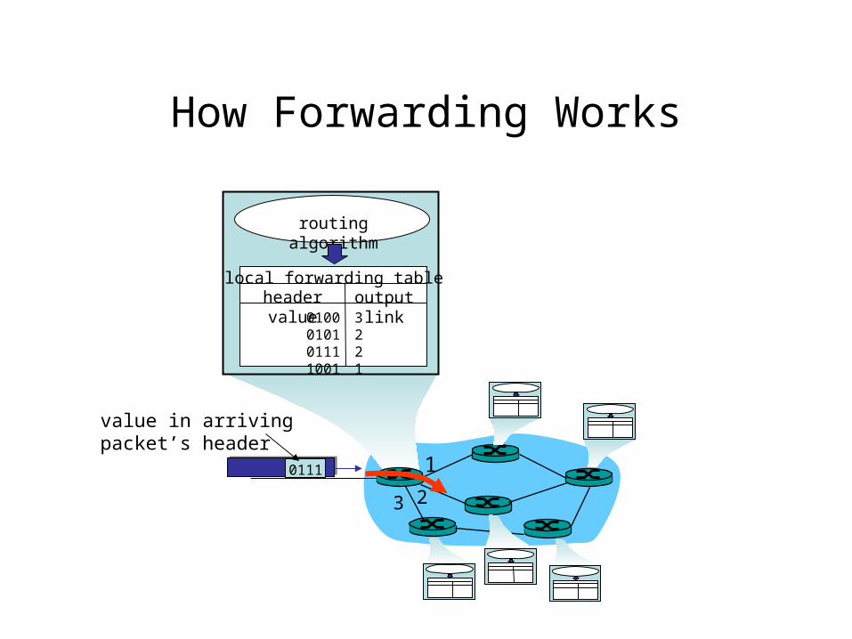
How Forwarding Works
1
23
0111
value in arrivingpacket’s header
routing algorithm
local forwarding tableheader value output link
0100010101111001
3221
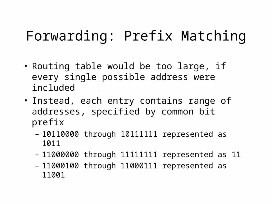
Forwarding: Prefix Matching
• Routing table would be too large, if every single possible address were included
• Instead, each entry contains range of addresses, specified by common bit prefix– 10110000 through 10111111 represented as 1011– 11000000 through 11111111 represented as 11– 11000100 through 11000111 represented as
11001
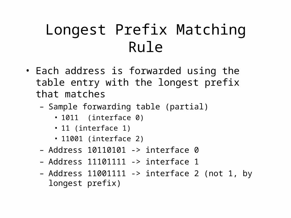
Longest Prefix Matching Rule
• Each address is forwarded using the table entry with the longest prefix that matches– Sample forwarding table (partial)
• 1011 (interface 0)
• 11 (interface 1)
• 11001 (interface 2)
– Address 10110101 -> interface 0– Address 11101111 -> interface 1– Address 11001111 -> interface 2 (not 1, by longest prefix)
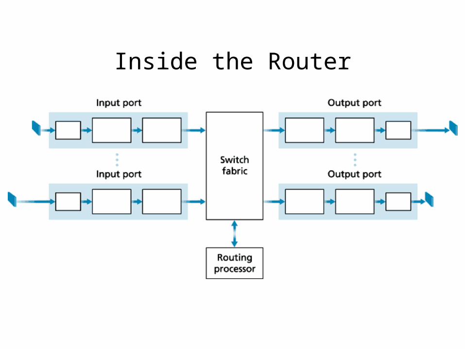
Inside the Router
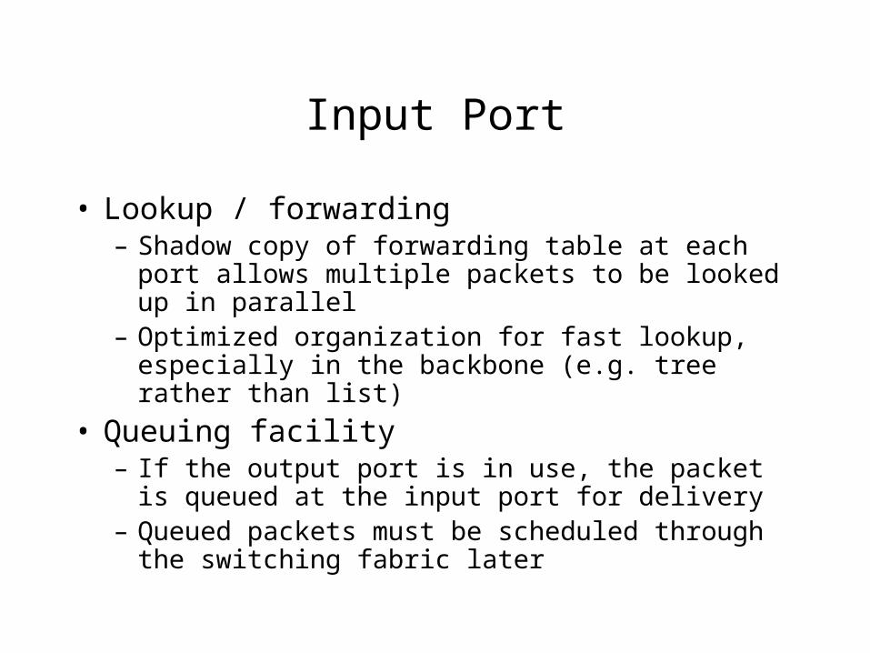
Input Port
• Lookup / forwarding– Shadow copy of forwarding table at each port
allows multiple packets to be looked up in parallel– Optimized organization for fast lookup, especially
in the backbone (e.g. tree rather than list)
• Queuing facility– If the output port is in use, the packet is queued at
the input port for delivery– Queued packets must be scheduled through the
switching fabric later
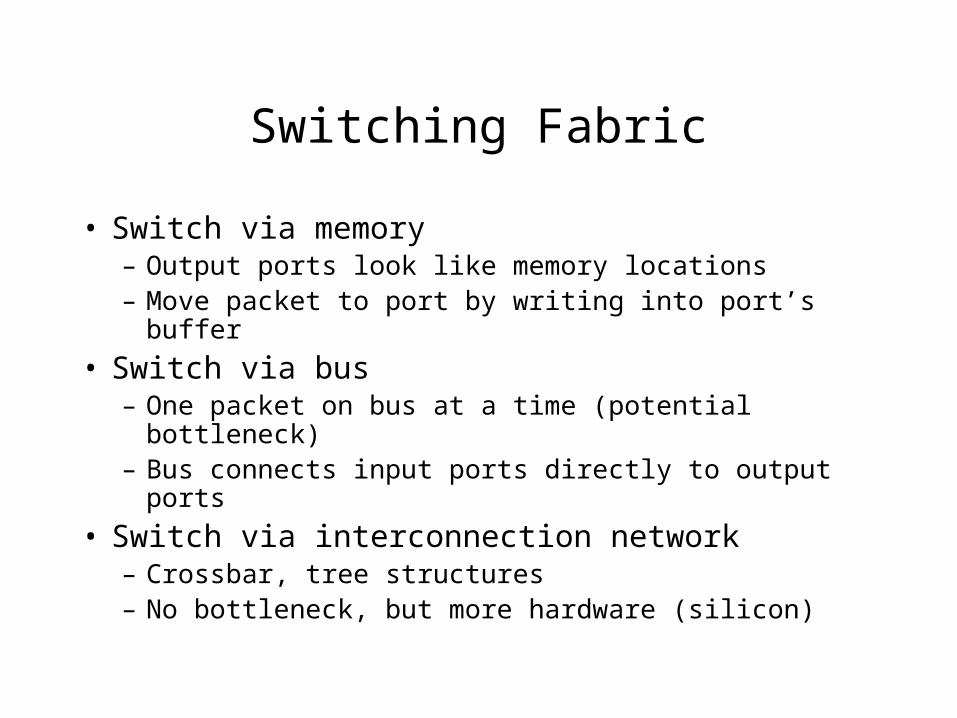
Switching Fabric
• Switch via memory– Output ports look like memory locations– Move packet to port by writing into port’s buffer
• Switch via bus– One packet on bus at a time (potential bottleneck)– Bus connects input ports directly to output ports
• Switch via interconnection network– Crossbar, tree structures– No bottleneck, but more hardware (silicon)
Output Ports
• Buffer• Queue (if buffer fills too fast)• Data link processing (protocol, encapsulation)
Where is the Queue?
• At input port– If designated output port is blocked– If switching fabric is unavailable
• At output port– When several inputs send to same output
simultaneously– Packet scheduler chooses which to send– If full, can either drop most recent packet, or
choose one already in the queue to drop
Internet Names and Addresses
• Network names, generally like:– garfield.cs.hiram.edu– groups.google.com
• Essentially hierarchical in “domains”– “garfield” in “computer science” at “hiram college” in the
“education” domain– “groups” of the “google” company in the “company” domain
• Translated to IP addresses by Domain Name Servers (DNS) -- (application covered in Ch. 2)
• IP v4 has 4 sets of 8 bits (0-255), e.g. 143.206.149.21
IP v4 Addresses
• 32 bits (4 groups of 8), e.g. 143.206.149.21• Leftmost N bits is “network prefix”
– Formerly classes A-D; value of prefix bits determined N– Now Classless InterDomain Routing (CIDR) specified N
directly: a.b.c.d/N
• Remaining bits identify individual hosts on a subnet– All nodes on a subnet can reach all other nodes on that
subnet without an intervening router
• A switch has a different address on each interface• Broadcast address: 255.255.255.255
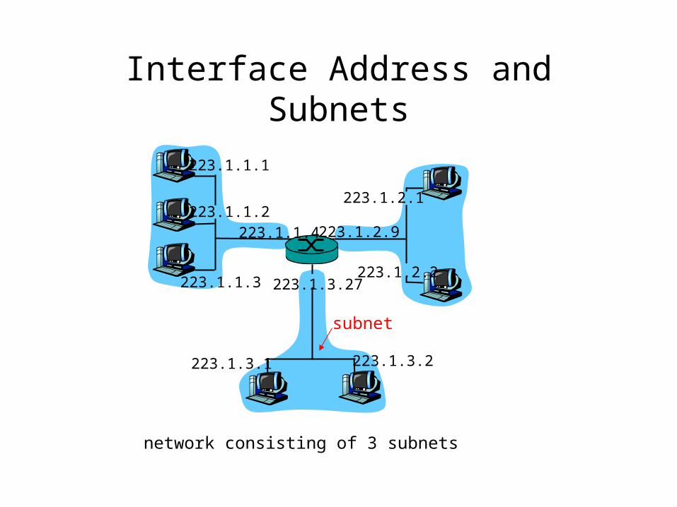
Interface Address and Subnets
223.1.1.1
223.1.1.2
223.1.1.3
223.1.1.4 223.1.2.9
223.1.2.2
223.1.2.1
223.1.3.2223.1.3.1
223.1.3.27
network consisting of 3 subnets
subnet
Getting an Address
• ISP gets its addresses from a bigger ISP or ICANN (also manages DNS names)
• Organization gets a block of addresses from an ISP (Internet Service Provider)
• Individual hosts gets address within organization’s block– Manual: system administrator gives host a fixed IP (needed
for externally available servers)– DHCP: protocol to request an available address for a finite
time (and get first-hop router and DNS info, too)• DHCP addresses can be reused by different subscribers if all
subscribers aren’t online all the time.
Network Address Translation (NAT)
• Router looks like a single device to the outside world (one IP address)
• Router looks like a DHCP server to the inside world (generates IP addresses)– Different home networks (etc) can all share the same
address space
• Each device inside the network has a unique subset of port numbers (so the router can address an incoming message correctly)– NAT translation table (outer port <–> inner host, inner port)
How NAT Works
• Message comes in from WAN– Based on port number, re-address it for LAN (internal
address and port)– Forward out appropriate interface to LAN– Host responds…
• Message goes out to LAN– Replace return address with WAN address and router port
• NAT Translation table contains necessary information to switch between LAN and WAN addresses
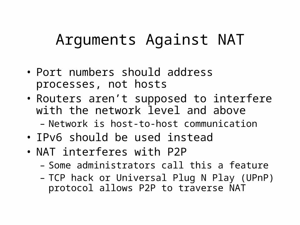
Arguments Against NAT
• Port numbers should address processes, not hosts
• Routers aren’t supposed to interfere with the network level and above– Network is host-to-host communication
• IPv6 should be used instead• NAT interferes with P2P
– Some administrators call this a feature– TCP hack or Universal Plug N Play (UPnP)
protocol allows P2P to traverse NAT
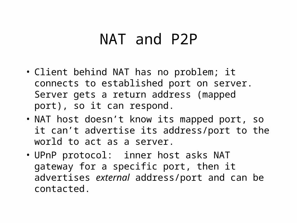
NAT and P2P
• Client behind NAT has no problem; it connects to established port on server. Server gets a return address (mapped port), so it can respond.
• NAT host doesn’t know its mapped port, so it can’t advertise its address/port to the world to act as a server.
• UPnP protocol: inner host asks NAT gateway for a specific port, then it advertises external address/port and can be contacted.
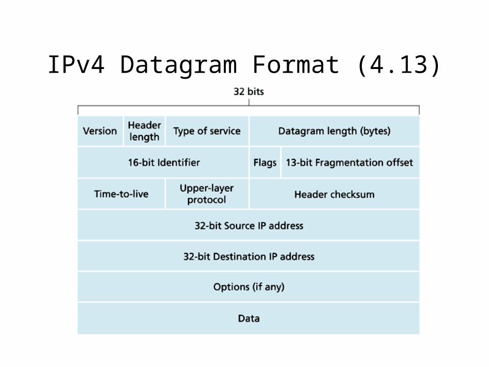
IPv4 Datagram Format (4.13)
Fragmentation
• Different networks can have different MTU (maximum transmission unit) sizes
• If a router has a packet that is too big for its network, it must fragment (break up) that packet– All fragments have the same id– Fragmentation offset indicates location in fragment– Flag is 1 for all fragments but last (to indicate last)
• Packets are reassembled at destination before passing up to transport layer
• Avoid fragmentation entirely if MSS (network layer) is small enough!
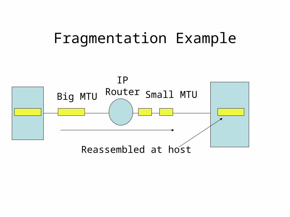
Fragmentation Example
Big MTU
IPRouter Small MTU
Reassembled at host
Other Network Layer Protocols
• ICMP (Internet Control Message Protocol)– For error reporting– E.g. destination unreachable (router sent ICMP
back when it couldn’t forward a packet)– Also used for ping, traceroute
• DHCP (Dynamic Host Configuration Protocol)– For assigning IP addresses dynamically and
usually temporarily– Will be discussed as part of the Link layer
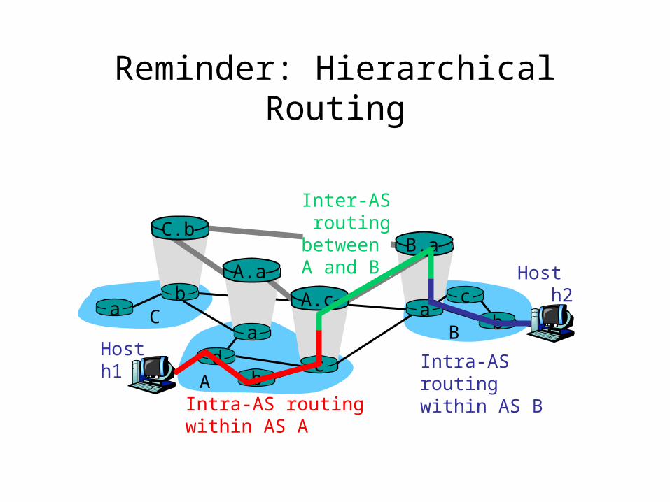
Reminder: Hierarchical Routing
Host h2
a
b
b
aaC
A
Bd c
A.a
A.c
C.bB.a
cb
Hosth1
Intra-AS routingwithin AS A
Inter-AS routingbetween A and B
Intra-AS routingwithin AS B
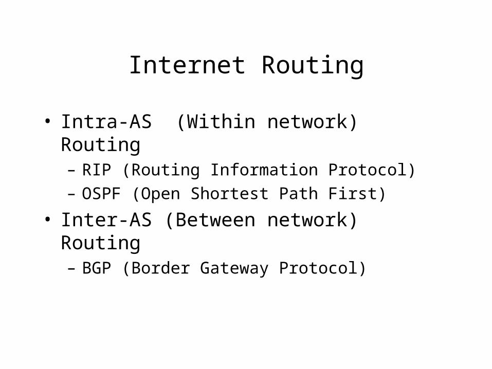
Internet Routing
• Intra-AS (Within network) Routing– RIP (Routing Information Protocol)– OSPF (Open Shortest Path First)
• Inter-AS (Between network) Routing– BGP (Border Gateway Protocol)
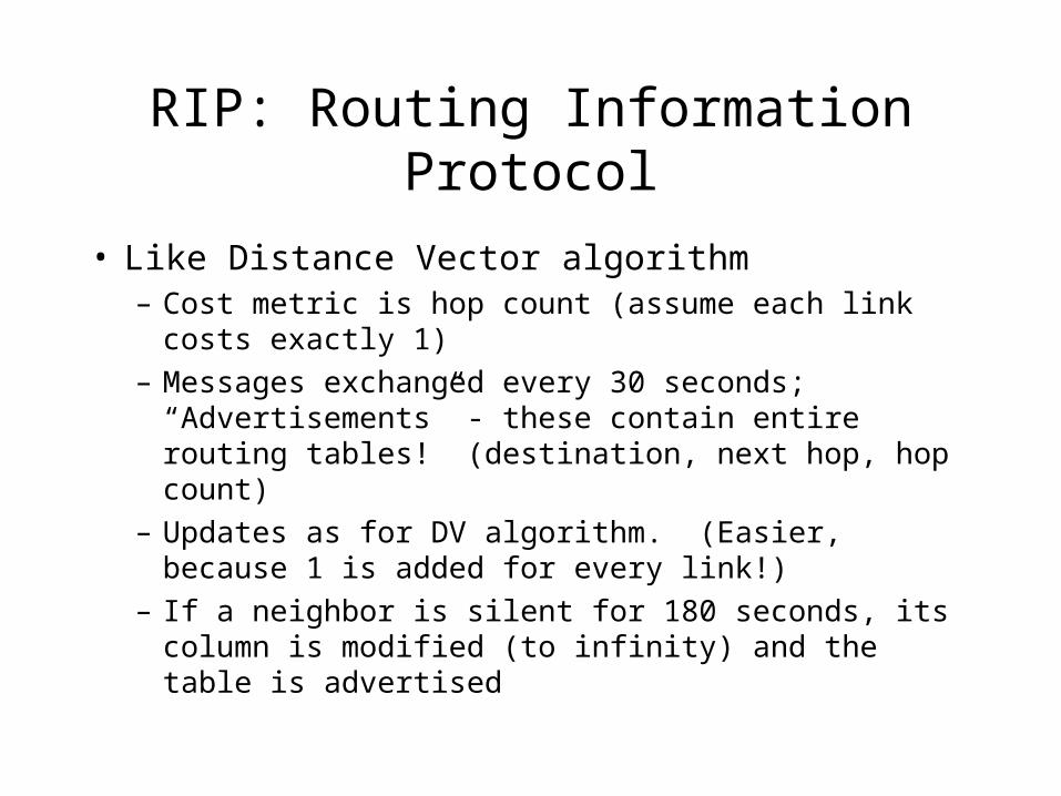
RIP: Routing Information Protocol
• Like Distance Vector algorithm– Cost metric is hop count (assume each link costs
exactly 1)– Messages exchanged every 30 seconds;
“Advertisements” - these contain entire routing tables! (destination, next hop, hop count)
– Updates as for DV algorithm. (Easier, because 1 is added for every link!)
– If a neighbor is silent for 180 seconds, its column is modified (to infinity) and the table is advertised
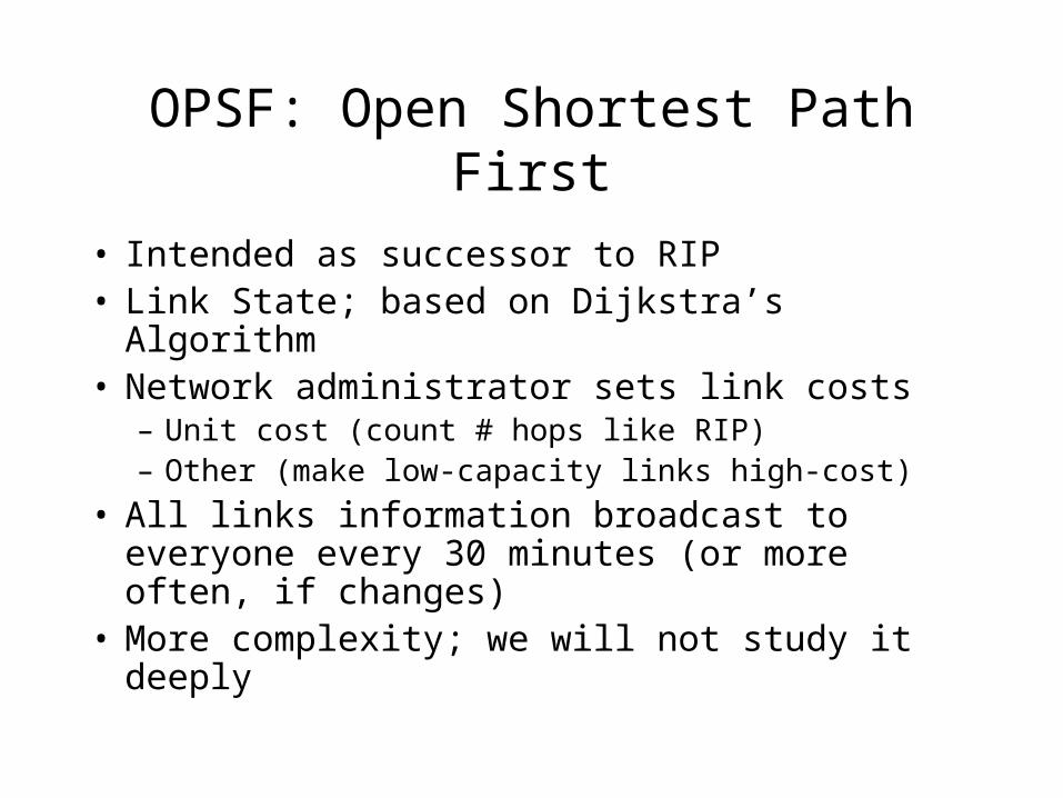
OPSF: Open Shortest Path First
• Intended as successor to RIP• Link State; based on Dijkstra’s Algorithm• Network administrator sets link costs
– Unit cost (count # hops like RIP)– Other (make low-capacity links high-cost)
• All links information broadcast to everyone every 30 minutes (or more often, if changes)
• More complexity; we will not study it deeply

BGP: Border Gateway Protocol
• For Inter-AS routing• Path vector protocol: neighboring routers
exchange detailed path information (not just the cost of next hop)
• Distributed like DV algorithm
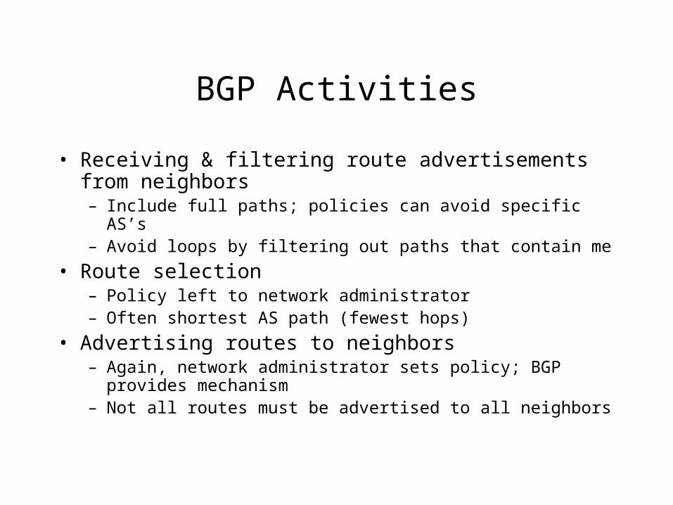
BGP Activities
• Receiving & filtering route advertisements from neighbors– Include full paths; policies can avoid specific AS’s– Avoid loops by filtering out paths that contain me
• Route selection– Policy left to network administrator – Often shortest AS path (fewest hops)
• Advertising routes to neighbors– Again, network administrator sets policy; BGP provides
mechanism– Not all routes must be advertised to all neighbors
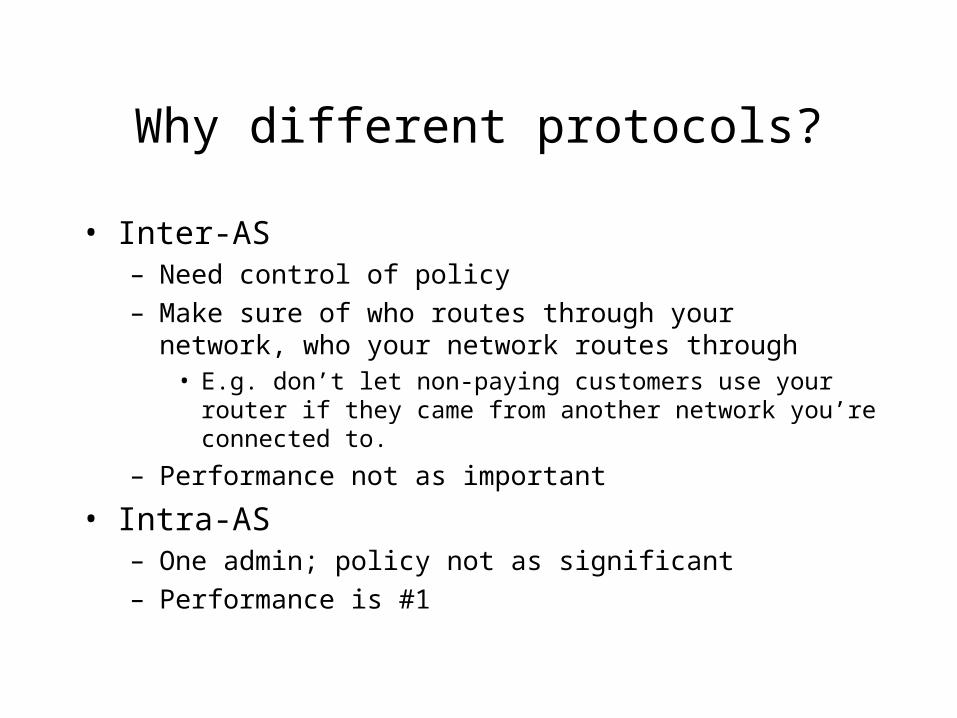
Why different protocols?
• Inter-AS– Need control of policy– Make sure of who routes through your network, who your
network routes through• E.g. don’t let non-paying customers use your router if they
came from another network you’re connected to.
– Performance not as important
• Intra-AS– One admin; policy not as significant– Performance is #1
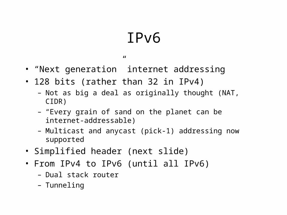
IPv6
• “Next generation” internet addressing• 128 bits (rather than 32 in IPv4)
– Not as big a deal as originally thought (NAT, CIDR)– “Every grain of sand on the planet can be internet-
addressable)– Multicast and anycast (pick-1) addressing now supported
• Simplified header (next slide)• From IPv4 to IPv6 (until all IPv6)
– Dual stack router– Tunneling
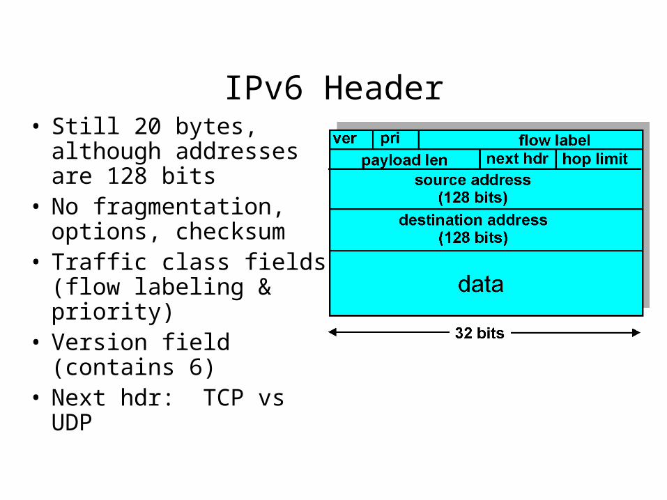
IPv6 Header• Still 20 bytes, although
addresses are 128 bits• No fragmentation,
options, checksum• Traffic class fields (flow
labeling & priority)• Version field (contains
6)• Next hdr: TCP vs UDP
From IPv4 to IPv6
• “Flag day” - pick a date and no longer support v4– Totally impractical, considering size and non-
centrality of Internet
• Dual-Stack approach– Every IPv6 node also can route IPv4 packets– Can determine if a node is v6 capable, or only v4
(DNS address tells this)– Once a packet is translated to v4, v6 info is lost (it
stays v4 until destination)

From IPv4 to IPv6 (continued)
• Tunneling– Same basic assumptions as dual stack– IPv6 datagram put in data field of an IPv4
datagram for transmission to/from IPv4 only router (Addressed to next IPv6 router on path)
– IPv4 header stripped, and IPv6 datagram sent when IPv6 capable node is reached
Summary: Network Layer
• Addressing (IPv4, IPv6)• Forwarding (prefix matching, NAT,
subnetting)• Routing (Link State vs. Distance Vector)
– Intra-AS (RIP (dv), OSPF (ls)– Inter-AS (BGP (dv – actually path vector)
• Administrative messages– ICMP (e.g. host unreachable, invalid port)