NCC 2019 Volume Three Amendment 1
285
Volume Three Plumbing Code of Australia 2019 Amendment 1
Transcript of NCC 2019 Volume Three Amendment 1

Volume Three
Plumbing Code of Australia
2019Amendment 1

Contents and Introduction
Contents and Introduction General Table of Contents
Copyright and licence notice
Introduction to the National Construction Code (NCC)
Introduction to NCC Volume Three
NCC 2019 Volume Three - Plumbing Code of Australia
Contents and Introduction
Amendment 1 Page 2

Contents and Features Introduction
NCC 2019 Volume Three - Plumbing Code of Australia
Contents and Introduction Copyright and licence notice..............................................................................................................................6 Introduction to the National Construction Code (NCC) ...................................................................................7 Introduction to NCC Volume Three ....................................................................................................................9
Section A Governing Requirements Section A Governing Requirements of the NCC ...........................................................................................13 Part A1 Interpreting the NCC ..........................................................................................................................14 Part A2 Compliance with the NCC..................................................................................................................16 Part A3 State or Territory compliance and the NCC .....................................................................................20 Part A4 Referenced documents......................................................................................................................21 Part A5 Documentation of design and construction ....................................................................................23 Part A6 Building classification .......................................................................................................................28 Part A7 United buildings .................................................................................................................................40
Section B Water Services Part B1 Cold water services............................................................................................................................45 Part B2 Heated water services........................................................................................................................48 Part B3 Non-drinking water services .............................................................................................................55 Part B4 Fire-fighting water services...............................................................................................................57 Part B5 Cross-connection control..................................................................................................................59 Part B6 Rainwater harvesting and use ..........................................................................................................65
Section C Sanitary Plumbing and Drainage Systems Part C1 Sanitary plumbing systems...............................................................................................................69 Part C2 Sanitary drainage system..................................................................................................................71
Section D Excessive Noise Part D1 Excessive noise..................................................................................................................................76
Section E Facilities Part E1 Facilities ..............................................................................................................................................80
Schedule 1 State and Territory Variations and Additions Schedule 1 State & Territory Appendices......................................................................................................83
Commonwealth of Australia Footnote: Other legislation affecting buildings ............................................................................................86
Australian Capital Territory Appendix Australian Capital Territory............................................................................................................92 Footnote: Other legislation affecting water and plumbing systems...........................................................93
New South Wales Section B Water services ................................................................................................................................97 Section C Sanitary plumbing and drainage systems .................................................................................100 Footnote: Other legislation affecting buildings ..........................................................................................102
General Table of Contents
Amendment 1 Page 3

Northern Territory Section B Water services ..............................................................................................................................106 Section C Sanitary plumbing and drainage systems .................................................................................107 Section D Excessive noise............................................................................................................................108 Footnote: Other legislation affecting buildings ..........................................................................................109
Queensland Section B Water services ..............................................................................................................................113
South Australia Section B Water services ..............................................................................................................................116 Section C Sanitary plumbing and drainage systems .................................................................................119 SA Section F On-site waste water systems.................................................................................................120 Schedule 3 Defined terms .............................................................................................................................124 Schedule 4 List of referenced documents...................................................................................................125 Footnote: Other legislation affecting buildings ..........................................................................................126
Tasmania Section A Governing requirements..............................................................................................................131 Section B Water services ..............................................................................................................................133 Section C Sanitary plumbing and drainage.................................................................................................137 Tas Section F Stormwater drainage systems..............................................................................................138 Tas Section G Heating, ventilation and air-conditioning systems ............................................................141 Tas Section H On-site waste water systems ...............................................................................................143 Tas Section I Materials and products certification and authorisation ......................................................162 Schedule 3 Definitions ..................................................................................................................................165 Schedule 4 Referenced documents .............................................................................................................167 Footnote: Other legislation affecting buildings ..........................................................................................169
Victoria Section B Water services ..............................................................................................................................172 Section C Sanitary plumbing and drainage systems .................................................................................174 Section D Excessive noise............................................................................................................................176 Vic Section F Stormwater drainage systems ..............................................................................................177 Vic Section G Heating, ventilation and air-conditioning systems.............................................................180 Vic Section H Low risk on-site liquid trade waste systems.......................................................................183 Footnote: Other legislation affecting buildings ..........................................................................................185
Western Australia Footnote: Other legislation affecting buildings ..........................................................................................188
Schedule 2 Abbreviations and Symbols Schedule 2 Abbreviations and symbols ......................................................................................................192
Schedule 3 Defined Terms Schedule 3 Definitions ..................................................................................................................................197
Schedule 4 List of Reference Documents Schedule 4 Referenced documents .............................................................................................................229
Schedule 5 Fire-resistance of Building Elements
NCC 2019 Volume Three - Plumbing Code of Australia Amendment 1 Page 4

Schedule 5 Fire-resistance of building elements .......................................................................................245
Schedule 6 Fire Hazard Properties Schedule 6 Fire hazard properties ...............................................................................................................255
Schedule 7 Fire Safety Verification Method 1.0 Preface ......................................................................................................................................................260 1.1 Purpose.....................................................................................................................................................261 1.2 How to use this Verification Method ......................................................................................................262 1.3 Performance-based design.....................................................................................................................263 1.4 Design scenarios: NCC Performance Requirements ...........................................................................265 1.5 Fire modelling to determine ASET .........................................................................................................268 2.1 Design scenario (BE)...............................................................................................................................269 2.2 Design scenario (UT) ...............................................................................................................................270 2.3 Design scenario (CS)...............................................................................................................................271 2.4 Design scenario (SF) ...............................................................................................................................272 2.5 Design scenario (HS)...............................................................................................................................273 2.6 Design scenario (VS) ...............................................................................................................................274 2.7 Design scenario (IS) ................................................................................................................................275 2.8 Design scenario (FI).................................................................................................................................276 2.9 Design scenario (UF) ...............................................................................................................................277 2.10 Design scenario (CF) .............................................................................................................................278 2.11 Design scenario (RC).............................................................................................................................279 2.12 Design scenario (SS) .............................................................................................................................280
History of PCA Adoption History of adoption ..........................................................................................................................................283
List of Amendments List of Amendments - NCC 2019 - Volume Three Amendment 1 ..............................................................288
NCC 2019 Volume Three - Plumbing Code of Australia Amendment 1 Page 5

Contents and Introduction
NCC 2019 Volume Three - Plumbing Code of Australia
© Commonwealth of Australia and the States and Territories of Australia 2020, published by the Australian Building Codes Board
The material in this publication is licensed under a Creative Commons Attribution-NoDerivatives—4.0 International licence, with the exception of:
any third party material•any trade marks, and•any images or photographs.•
You may not make derivatives of this publication, but may only use a verbatim copy. More information on this CC BY ND license is set out at the Creative Commons Website. Enquiries about this publication can be sent to: Australian Building Codes Board GPO Box 2013 CANBERRA ACT 2601 Phone: 1300 134 631 Email: [email protected] www.abcb.gov.au.
Attribution Use of all or part of this publication must include the following attribution: © Commonwealth of Australia and the States and Territories 2020, published by the Australian Building Codes Board.
Disclaimer By accessing or using this publication, you agree to the following: While care has been taken in the preparation of this publication, it may not be complete or up-to-date. You can ensure that you are using a complete and up-to-date version by checking the Australian Building Codes Board website (www.abcb.gov.au). The Australian Building Codes Board, the Commonwealth of Australia and States and Territories of Australia do not accept any liability, including liability for negligence, for any loss (howsoever caused), damage, injury, expense or cost incurred by any person as a result of accessing, using or relying upon this publication, to the maximum extent permitted by law. No representation or warranty is made or given as to the currency, accuracy, reliability, merchantability, fitness for any purpose or completeness of this publication or any information which may appear on any linked websites, or in other linked information sources, and all such representations and warranties are excluded to the extent permitted by law. This publication is not legal or professional advice. Persons rely upon this publication entirely at their own risk and must take responsibility for assessing the relevance and accuracy of the information in relation to their particular circumstances.
First Published: February 2019 Print version: 2.1 Release date: July 2020
Copyright and licence notice
Amendment 1 Page 6

Contents and Introduction
NCC 2019 Volume Three - Plumbing Code of Australia
About the NCC The NCC is Australia’s primary set of technical design and construction provisions for buildings. As a performance-based code, it sets the minimum required level for the safety, health, amenity, accessibility and sustainability of certain buildings. It primarily applies to the design and construction of new buildings, and plumbing and drainage systems in new and existing buildings. In some cases it may also apply to structures associated with buildings and new building work or new plumbing and drainage work in existing buildings. The Australian Building Codes Board (ABCB), on behalf of the Australian Government and each State and Territory government, produces and maintains the NCC. When determining the content of the NCC, the ABCB seeks to—
ensure requirements have a rigorously tested rationale; and•effectively and proportionally address applicable issues; and•create benefits to society that outweigh costs; and•consider non-regulatory alternatives; and•consider the competitive effects of regulation; and•not be unnecessarily restrictive.•
The primary users of the NCC include architects, builders, plumbers, building surveyors, hydraulic consultants, engineers and other building and plumbing related professions and trades.
Format of the NCC The NCC is published in three volumes. The Building Code of Australia (BCA) is Volumes One and Two of the NCC and the Plumbing Code of Australia (PCA) is Volume Three of the NCC.
Components of the NCC The NCC provides the technical provisions for the design and construction of buildings and other structures, and plumbing and drainage systems. NCC Volume One primarily covers the design and construction of multi-residential, commercial, industrial and public assembly buildings and some associated structures. NCC Volume Two primarily covers the design and construction of smaller scale buildings including houses, small sheds, carports and some associated structures. NCC Volume Three covers the design, construction and maintenance of plumbing and drainage systems in new and existing buildings. Each volume contains—
Governing Requirements; and•Performance Requirements; and•compliance options to meet the NCC requirements; and•State and Territory variations and additions.•
The NCC uses building classifications to identify requirements for different intended purposes of buildings or parts of buildings. A building classification relates to the characteristics and the intended use of the building. Information on building classifications is found in Part A6 of the Governing Requirements.
Legislative arrangements and the NCC The NCC is given legal effect through State and Territory, or other statutory authority, building and plumbing legislation. These Acts and Regulations set out the legal framework and administration mechanisms for the NCC to support the design and construction of buildings. The dates of adoption of the NCC are determined by State and Territory building and plumbing administrations.
How to use the NCC Each volume of the NCC is split into two main sections:
Introduction to the National Construction Code (NCC)
Amendment 1 Page 7

Contents and Introduction
NCC 2019 Volume Three - Plumbing Code of Australia
1. Administrative requirements contained within the Governing Requirements.2. Technical requirements contained within the remaining sections of the NCC.The Governing Requirements provide the rules and instructions for using and complying with the NCC. They are vital in understanding how the technical requirements of the NCC should be applied to any particular situation. The Governing Requirements are also important in understanding how the NCC fits with the building and plumbing regulatory framework within Australia.
NCC resources The NCC has resources created to make the code easier to understand and apply. These resources are available from the ABCB website at: www.abcb.gov.au.
Amendment 1 Page 8

Contents and Introduction
NCC 2019 Volume Three - Plumbing Code of Australia
About NCC Volume Three NCC Volume Three contains technical requirements for the design and construction for plumbing and drainage systems in new and existing buildings. Volume Three applies to these systems in all classes of buildings whenever plumbing work is carried out. Volume Three additionally applies to sites where water services are constructed independent of buildings.
Components of NCC Volume Three NCC Volume Three contains the following Sections:
Section A – Governing Requirements, common across the NCC•Section B – Water services•Section C – Sanitary plumbing and drainage systems•Section D – Excessive noise•Section E – Facilities•Schedules –•
State and Territory Appendices•Abbreviation and symbols•NCC defined terms•Referenced documents•Fire-resistance of building elements•Fire hazard properties•Fire Safety Verification Method.•
Section A contains the mandatory Governing Requirements for the NCC. Sections B to E contain mandatory Performance Requirements and the compliance options to satisfy compliance with the NCC.
Introduction to NCC Volume Three
Amendment 1 Page 9

Governing Requirements
Section AGoverning Requirements
Section A Governing Requirements of the NCC
Part A1 Interpreting the NCC
Part A2 Compliance with the NCC
Part A3 State or Territory compliance and the NCC
Part A4 Referenced documents
Part A5 Documentation of design and construction
Part A6 Building classification
Part A7 United buildings
NCC 2019 Volume Three - Plumbing Code of Australia
Section A Governing Requirements
Amendment 1 Page 10

Governing Requirements
NCC 2019 Volume Three - Plumbing Code of Australia
Section A Governing Requirements of the NCC Introduction to this Section
Part A1 Interpreting the NCC Introduction to this Part A1.0 Interpretation
Part A2 Compliance with the NCC Introduction to this Part A2.0 Compliance A2.1 Compliance with the Performance Requirements A2.2 Performance Solution A2.3 Deemed-to-Satisfy Solution A2.4 A combination of solutions
Part A3 State or Territory compliance and the NCC Introduction to this Part A3.0 State and Territory compliance
Part A4 Referenced documents Introduction to this Part A4.0 Referenced documents A4.1 Differences between referenced documents and the NCC A4.2 Adoption of referenced documents
Part A5 Documentation of design and construction Introduction to this Part A5.0 Suitability A5.1 Evidence of suitability—Volumes One, Two and Three A5.2 Evidence of suitability—Volumes One and Two A5.3 Evidence of suitability—Volume Three A5.4 Fire-resistance of building elements A5.5 Fire hazard properties A5.6 Resistance to the incipient spread of fireA5.7 Labelling of Aluminium Composite Panels
Part A6 Building classification Introduction to this Part A6.0 Determining a building classification A6.1 Class 1 buildings A6.2 Class 2 buildings A6.3 Class 3 buildings A6.4 Class 4 buildings A6.5 Class 5 buildings A6.6 Class 6 buildings A6.7 Class 7 buildings A6.8 Class 8 buildings A6.9 Class 9 buildings A6.10 Class 10 buildings and structures A6.11 Multiple classifications
Part A7 United buildings Introduction to this Part
Section A Governing Requirements
Amendment 1 Page 11

Governing Requirements
NCC 2019 Volume Three - Plumbing Code of Australia
A7.0 United buildings A7.1 Alterations in a united building
Amendment 1 Page 12

Governing Requirements
NCC 2019 Volume Three - Plumbing Code of Australia
Introduction to this Section The Governing Requirements of the NCC provide the rules and instructions for using and complying with the NCC. They include the following:
Interpreting the NCC.•Complying with the NCC.•Application of the NCC in States and Territories.•Applying documents referenced in the NCC.•Documenting the suitability of the design, construction and/or use of materials to comply with the NCC.•Classifying buildings by their characteristics and intended use.•
Section A Governing Requirements of the NCC
Amendment 1 Page 13

Governing Requirements
NCC 2019 Volume Three - Plumbing Code of Australia
Introduction to this Part This Part explains important concepts on how the NCC must be interpreted and applied. There are certain conventions and approaches that need to be taken into account when using the NCC. This includes interpreting specific language and terms. This is critical in understanding the intended technical and legal meaning of the NCC. This Part also explains the difference between the mandatory parts of the NCC and parts that are only explanatory or guidance in nature.
A1.0 Interpretation (1) The following components of the NCC are non-mandatory and informative:
(a) Content identified as “explanatory information”.
(b) For Volumes One and Two, the “Introduction to this Part or Section” information, located at the beginning ofeach Part or Section.
(c) For Volume Three, the “Introduction to this Section” information, located at the beginning of each Section.
(2) Words in italics must be interpreted in accordance with—
(a) definitions provided in Schedule 3, unless the contrary intention appears; and
(b) additional definitions in State or Territory appendices, as appropriate.
(3) The NCC must be interpreted and applied in accordance with the following:
(a) A reference to a building is a reference to an entire building or part of a building (as the case requires).
(b) A reference to a plumbing or drainage solution, or product in Volume Three is a reference to an entire installation,system or product, or part of an installation, system or product (as the case requires).
(c) A reference in a Performance Requirement to “the degree necessary” means—
(i) that consideration of all the criteria referred to in the Performance Requirement will determine the outcomeappropriate to the circumstances; and
(ii) that in certain cases it may not be necessary to incorporate any specific measures to meet the relevantPerformance Requirement.
(d) For Volume Three the “Introduction to this Part” information, located at the beginning of each Part, is mandatoryand is provided to specify where each Part applies.
(e) An “Application” statement is mandatory and is provided to specify where and when a requirement or provisionapplies.
(f) A “Limitation” statement is mandatory and is provided to specify where and when the application of a requirementor provision is limited to a certain circumstance.
(g) An “Exemption” statement is mandatory and is provided to specify where or when a requirement or provisiondoes not need to be complied with.
(h) A “Note” is part of a provision or requirement and provides additional mandatory instructions.
(i) Figures in the NCC are used to illustrate specific issues referenced in the associated text. They are not to beconstrued as containing all design information that is required for that particular building element or situation.
(j) The defined symbols and abbreviations listed in Schedule 2.
(4) A reference to a building class is understood to be a reference to all the sub-classifications of that class.
(5) The following sub-classifications apply:
(a) Classes 1a and 1b are sub-classifications of Class 1.
(b) Classes 7a and 7b are sub-classifications of Class 7.
Part A1 Interpreting the NCC
Note: For Volume Three, if a word is not defined in Schedule 3, the meaning (if any) attributed to it under AS/NZS 3500.0 Glossary of Terms should be used unless the contrary intention appears.
Amendment 1 Page 14

Governing Requirements
NCC 2019 Volume Three - Plumbing Code of Australia
(c) Classes 9a, 9b and 9c are sub-classifications of Class 9.
(d) Classes 10a, 10b and 10c are sub-classifications of Class 10.
(6) A reference to a sub-classification is solely to that sub-classification.Tas A1.0(7)
Explanatory information: Explanatory information and Introduction to this Section information contained in the NCC or Introduction to this Part information contained in Volumes One and Two of the NCC are non-mandatory and are provided for guidance purposes only. This informative material should be read in conjunction with the technical provisions of the NCC. Any statements made in the informative and guidance components of the NCC should not be taken to override the NCC. Unlike the NCC, which is adopted by legislation, the informative and guidance components are not called up into legislation and they do not cover State and Territory variations and additions. Because informative and guidance components of the NCC do not have regulatory force, the ABCB accepts no responsibility for its contents when applied to specific buildings or any liability which may result from its use. Defined words provide the precise meaning and expressions of key words used for understanding and complying with the NCC. Where a word is not defined in the NCC, the relevant common meaning of the word should be used. Generally, a reference to a building is a reference to the whole building, regardless of classification. However, when a provision is applicable to a specific class or classes of building, that reference to a building may be a reference to the whole building or part of the building depending on how the building is classified. Whether a provision applies or not depends on the circumstances of the case and the circumstances in which the reference is made. For example, where a building has a single classification, a reference to a building in the NCC is understandably a reference to a whole building. However, where a building has parts of different classification, unless the contrary intention appears (i.e. there is a specific reference to the whole building), a reference to a building in the NCC is a reference to the relevant part of the building. This means that each part of the building must comply with the relevant provisions for its classification. A number of the Performance Requirements of the NCC use the expression “to the degree necessary” or “appropriateto”. These expressions provide flexibility by allowing appropriate authorities to determine the degree of compliancenecessary in a particular case. Therefore any part of the NCC that uses these expressions should be referenced against the requirements of the appropriate authority. For example, an appropriate authority might judge that an item need notbe installed, or a particular level of performance be achieved. Application, Limitation, and Exemption statements are used to identify provisions that may or may not apply in certain situations, to varying degrees. Classes 1a and 1b, 7a and 7b, 9a, 9b and 9c, and 10a, 10b and 10c are separate classifications. In the NCC, when the designation ‘a’, ‘b’ or ‘c’ is not applied, the reference is to all buildings of the general class. For example, ‘Class 9b’ refers only to Class 9b buildings, but ‘Class 9’ refers to Classes 9a, 9b and 9c. Figures are used to explain the requirements of a particular clause. To ensure the context of the requirement is clearly understood, adjacent construction elements of the building that would normally be required in that particular situationare not always shown. Accordingly, aspects of figures that are not shown should not be interpreted as meaning these construction details are not required. Therefore a figure must not be used as an indication of the full constructionrequirements in a given situation, as the only available option, or a substitute for referencing appropriate construction requirements (in other sources) for a given clause.
A1.0
Amendment 1 Page 15

Governing Requirements
NCC 2019 Volume Three - Plumbing Code of Australia
Introduction to this Part This Part explains the possible methods of demonstrating compliance with the NCC. It explains the various compliance pathways within the NCC and the appropriate steps that must be taken for each of these pathways.
A2.0 Compliance Compliance with the NCC is achieved by complying with—
(1) the Governing Requirements of the NCC; and
(2) the Performance Requirements.
A2.1 Compliance with the Performance Requirements Performance Requirements are satisfied by one of the following, as shown in Figure 1:
(1) A Performance Solution.
(2) A Deemed-to-Satisfy Solution.
(3) A combination of (1) and (2).
Figure 1: NCC compliance option structure
A2.2 Performance Solution
(1) A Performance Solution is achieved by demonstrating—
(a) compliance with all relevant Performance Requirements; or
(b) the solution is at least equivalent to the Deemed-to-Satisfy Provisions.
(2) A Performance Solution must be shown to comply with the relevant Performance Requirements through one or acombination of the following Assessment Methods:
(a) Evidence of suitability in accordance with Part A5 that shows the use of a material, product, plumbing anddrainage product, form of construction or design meets the relevant Performance Requirements.
(b) A Verification Method including the following:
(i) The Verification Methods provided in the NCC.
(ii) Other Verification Methods, accepted by the appropriate authority that show compliance with the relevantPerformance Requirements.
(c) Expert Judgement.
(d) Comparison with the Deemed-to-Satisfy Provisions.
(3) Where a Performance Requirement is satisfied entirely by a Performance Solution, in order to comply with (1) the
Part A2 Compliance with the NCC
Amendment 1 Page 16

Governing Requirements
NCC 2019 Volume Three - Plumbing Code of Australia
following method must be used to determine the Performance Requirement or Performance Requirements relevantto the Performance Solution:
(a) Identify the relevant Performance Requirements from the Section or Part to which the Performance Solutionapplies.
(b) Identify Performance Requirements from other Sections or Parts that are relevant to any aspects of thePerformance Solution proposed or that are affected by the application of the Performance Solution.
A2.2
(4) Where a Performance Requirement is proposed to be satisfied by a Performance Solution, the following steps must be undertaken:
(a) Prepare a performance-based design brief in consultation with relevant stakeholders.
(b) Carry out analysis, using one or more of the Assessment Methods listed in (2), as proposed by the performance-based design brief.
(c) Evaluate results from (b) against the acceptance criteria in the performance-based design brief.
(d) Prepare a final report that includes—
(i) all Performance Requirements and/or Deemed-to-Satisfy Provisions identified through A2.2(3) or A2.4(3) as applicable; and
(ii) identification of all Assessment Methods used; and
(iii) details of steps (a) to (c); and
(iv) confirmation that the Performance Requirement has been met; and
(v) details of conditions or limitations, if any exist, regarding the Performance Solution.
A2.3 Deemed-to-Satisfy Solution
(1) A
solution that complies with the Deemed-to-Satisfy Provisions is deemed to have met the PerformanceRequirements.
(2) A
Deemed-to-Satisfy Solution can show compliance with the Deemed-to-Satisfy Provisions through one or more ofthe following Assessment Methods:
(a) Evidence of suitability in accordance with Part A5 that shows the use of a material, product, plumbing anddrainage product, form of construction or design meets a Deemed-to-Satisfy Provision.
(b) Expert Judgement.
(3) For Volume Two:
(a) Where an acceptable construction manual and an acceptable construction practice contained in the same Partare considered to satisfy the same component of a Performance Requirement, in order to comply with theDeemed-to-Satisfy Provisions it is only necessary to satisfy—
(i) the appropriate acceptable construction manual; or
(ii) the appropriate acceptable construction practice.
(b) Where an acceptable construction manual and an acceptable construction practice contained in the same Partare deemed to satisfy different components of a Performance Requirement, compliance with the Deemed-to-Satisfy Provisions may require satisfying both the listed acceptable construction manual and the acceptableconstruction practice for their specific components unless otherwise stated.
Note: A2.2(4) does not take affect until 1 July 2021.
Amendment 1 Page 17

Governing Requirements
NCC 2019 Volume Three - Plumbing Code of Australia
A2.4 A combination of solutions
(1) Performance Requirements may be satisfied by using a combination of Performance Solutions and Deemed-to-Satisfy Solutions.
(2) When using a combination of solutions, compliance can be shown through the following, as appropriate:
(a) A2.2 for assessment against the relevant Performance Requirements.
(b) A2.3 for assessment against the relevant Deemed-to-Satisfy Provisions.
(3) Where a Performance Requirement is satisfied by a Performance Solution in combination with a Deemed-to-SatisfySolution, in order to comply with (1), the following method must be used to determine the Performance Requirementor Performance Requirements relevant to the Performance Solution:
(a) Identify the relevant Deemed-to-Satisfy Provisions of each Section or Part that are to be the subject of thePerformance Solution.
(b) Identify the Performance Requirements from the same Sections or Parts that are relevant to the identifiedDeemed-to-Satisfy Provisions.
(c) Identify Performance Requirements from other Sections or Parts that are relevant to any aspects of thePerformance Solution proposed or that are affected by the application of the Deemed-to-Satisfy Provisions thatare the subject of the Performance Solution.
Explanatory information:To comply with the NCC, a solution must achieve compliance with the Governing Requirements and the Performance Requirements. The Governing Requirements contain requirements about how the Performance Requirements mustbe met. Performance Requirements outline the minimum necessary standards different buildings or building elements mustattain. The Performance Requirements are the only NCC technical provisions that must be satisfied.In some instances, State and Territory variations and additions may also be applicable to certain Performance
A2.2
Requirements.A solution may be partly a Performance Solution and partly a Deemed-to-Satisfy Solution. However, no matter whatmethod is chosen, building proponents need to always meet the Performance Requirements of the NCC.A2.2(2)(b)(ii) provides for the use of Verification Methods that are not listed in the NCC. A Verification Method mayinclude—
1. a calculation, using analytical methods or mathematical models; or2. a test, using a technical procedure, either on-site or in a laboratory, to directly measure the extent to which the
Performance Requirements have been met; or3. an inspection (and inspection report); or4. any other acceptable form of certification.Any Verification Method used must be acceptable to the appropriate authority.A Performance Solution must comply with all applicable Performance Requirements of the NCC. A Performance Solutionprovides a tailored solution to meet the intended objective of the Performance Requirements. A Performance Solutionmust comply with all relevant Performance Requirements and must be verified using one or a combination of thefollowing Assessment Methods:
• Evidence of suitability.• Verification Method.• Expert Judgement.• Comparison with the Deemed-to-Satisfy Provisions.
For example, building proponents who wish to know what has to be done to satisfy the fire safety Performance Requirements for a particular building can either follow the Deemed-to-Satisfy Provisions or develop a Performance Solution. Guidance on how to develop Performance Solutions can be found on the ABCB website at: www.abcb.gov.au. The ABCB Resource Library contains information on the development of Performance Solutions for both building and plumbing. A Deemed-to-Satisfy Solution is achieved by following all appropriate Deemed-to-Satisfy Provisions in the NCC. The Deemed-to-Satisfy Provisions are prescriptive (i.e. like a recipe book, they tell you how, what and in which location things must be done). They include materials, components, design factors, and construction methods that, if used, are deemed to meet the Performance Requirements, hence the term “Deemed-to-Satisfy”.
Amendment 1 Page 18

Governing Requirements
NCC 2019 Volume Three - Plumbing Code of Australia
A Deemed-to-Satisfy Solution may be verified using one or a combination of the following Assessment Methods:
Evidence of suitability.•Expert Judgement.•
Some Performance Requirements are without Deemed-to-Satisfy Solutions. Compliance with these Performance Requirements must be achieved by using a Performance Solution.In Section 3 of Volume Two the Deemed-to-Satisfy Provisions are divided into two compliance pathways: “acceptable construction practices” and “acceptable construction manuals”:
“Acceptable construction practices” are some of the most common forms of national construction practices•and are written into Section 3.“Acceptable construction manuals” are the deemed-to-satisfy referenced documents.•
A2.4
In general, either an “acceptable construction practice” or an “acceptable construction manual” may be used as options when proposing a Deemed-to-Satisfy Solution.Acceptable construction practices are Deemed-to-Satisfy Provisions that are considered to meet the legislative requirements for Class 1 and Class 10 buildings. There is no obligation to adopt any particular option contained in the acceptable construction practices, if it is preferred to meet the Performance Requirement in some other way.However, if one of the options described in these provisions is not complied with, then the appropriate authority must be satisfied that the Performance Requirements have been met.When designing a building or plumbing or drainage system, both Performance Solutions and Deemed-to-Satisfy Solutions can be used to achieve compliance with Performance Requirements. A combination of solutions may be used to satisfy a single Performance Requirement. This may include occasions where a specific Performance Requirement covers a number of elements of a building or plumbing or drainage system.No NCC provision can be considered in isolation. Any departure from the Deemed-to-Satisfy Provisions for a Performance Solution needs to be assessed against the relevant Performance Requirements within the relevant NCC
Section or Part. Additionally, the proposed Performance Solution may also impact on other Performance Requirements in other Sections or Parts. Thus, these additional Performance Requirements need to be considered in relation to the subject Performance Solution. A2.2(3) and A2.4(3) set out the methods for determining which Performance Requirements are relevant.It is important that a holistic approach is used when determining the appropriate Performance Requirements.More information on NCC compliance methods is located at www.abcb.gov.au.
A2.4(2)(a) references A2.2. Therefore when using a combination of Performance Solutions and Deemed-to-Satisfy Solutions it is necessary to comply with A2.2(4) where a Performance Requirement is proposed to be satisfied by a Performance Solution.
Amendment 1 Page 19

Governing Requirements
NCC 2019 Volume Three - Plumbing Code of Australia
Introduction to this Part This Part explains applying the NCC in accordance with State or Territory legislation. The NCC has legal effect through references in relevant State and Territory building and plumbing legislation. Although the NCC is a nationally consistent code, there are some situations where a State or Territory enforce a variation, addition or deletion to it. This Part also explains how these variations, additions and deletions apply.
A3.0 State and Territory compliance (1) For application within a particular State or Territory, the Volumes of the NCC comprise inclusively of—
(a) Sections A to J and associated schedules of Volume One; and
(b) Sections 1 to 3 and associated schedules of Volume Two; and
(c) Sections A to E and associated schedules of Volume Three.
(2) State or Territory variations, additions and deletions must be complied with in conjunction with the NCC.
(3) The NCC is subject to, and may be overridden by, State or Territory legislation.
(4) For Volumes One and Three, State and Territory variations, additions and deletions are contained in Schedule 1.
(5) For Volume Two, State and Territory variations, additions and deletions are contained throughout the Volume and inSchedule 1.
(6) State and Territory variations and deletions are identified throughout the NCC.
Part A3 State or Territory compliance and the NCC
Explanatory information: The NCC is given legal effect by building regulatory legislation in each State and Territory. This legislation consists of an Act of Parliament and subordinate legislation which empowers the regulation of certain aspects of building and plumbing, and contains the administrative provisions necessary to give effect to the legislation. Although the NCC is a national code, in some instances it is necessary for a State or Territory to vary or apply additional requirements specific to their jurisdiction. A3.0(2) highlights that these variations, additions or deletions must be applied in conjunction with the NCC provisions. Typically, these variations, additions or deletions override the requirements contained within the NCC. Any provision of the NCC may be overridden by, or subject to, State or Territory legislation. The NCC must therefore be read in conjunction with that legislation. Any queries on such matters should be referred to the State or Territory authority responsible for building and plumbing regulatory matters. Where a requirement or provision of the NCC is subject to a State or Territory variation, addition, or deletion, a reference to the appropriate provision in Schedule 1 is included with that requirement or provision.
Amendment 1 Page 20

Governing Requirements
NCC 2019 Volume Three - Plumbing Code of Australia
Introduction to this Part This Part explains how documents referenced in the NCC are adopted and applied. The NCC itself does not contain details of every design and construction requirement for a building or plumbing or drainage system. As such, the NCC calls uponor “references” other documents with this information. These are called NCC referenced documents. Examples of these are Australian Standards, ABCB protocols, ABCB standards and other publications. There are multiple types of referenced documents. A primary referenced document is one referenced in Schedule 4 of the NCC. A secondary referenced document is one referenced in a primary referenced document. Other referenced documents are referenced by secondary and subsequently referenced documents.
A4.0 Referenced documents (1) A reference in the NCC to a document refers to the edition or issue and any amendment listed in Schedule 4.
(2) A document referenced in the NCC is only applicable in the context in which the document is quoted.
Volume Three Tas A4.0(3)(3) Where a new edition, issue or amendment of a primary referenced document is not listed under Schedule 4, the
new edition, issue or amendment is not referenced for the purposes of the NCC.
(4) Any document referenced in a primary referenced document is known as a secondary referenced document.
(5) A reference in a primary referenced document to a secondary or other referenced document is a reference to thedocument as it existed at the time of publication of the primary referenced document.
A4.1 Differences between referenced documents and the NCC The NCC overrules any difference between the NCC and a primary referenced document, including any secondary referenced document.
A4.2 Adoption of referenced documents The NCC does not require compliance with requirements in relation to the following matters where they are prescribed in a referenced document:
(1) The rights, responsibilities or obligations between the manufacturer, supplier or purchaser.
(2) The responsibilities of any trades person or other building operative, architect, engineer, authority, or other personor body.
(3) The submission for approval of any material, building component, form or method of construction, to any person,authority or body other than those empowered under State or Territory legislation to give that approval.
(4) The submission of a material, product, form of construction or design to any person, authority or body for an opinion.
(5) Any departure from the NCC, rule, specification or provision at the sole discretion of the manufacturer or purchaser,or by arrangement or agreement between the manufacturer and purchaser.
Part A4 Referenced documents
Exemption 1: If the secondary or other referenced document is also a primary referenced document, A4.0(5) does not apply.
Exemption 1: A4.1 does not apply to acceptable construction manuals when used in their entirety to comply with requirements of the NCC unless otherwise stated.
Explanatory information: Schedule 4 is only mandatory to Deemed-to-Satisfy Provisions, Verification Methods and Schedules 3, 5 and 6.However, referenced documents are only applicable to the NCC provision that references the document. A proponent undertaking a Performance Solution can use any element or edition of any document, if they help satisfythe Performance Requirements. They do not need to use the documents listed in Schedule 4.Schedule 4 lists the specific edition of the Standard or other document adopted, including any amendments considered
Amendment 1 Page 21

Governing Requirements
NCC 2019 Volume Three - Plumbing Code of Australia
appropriate for Schedule 3, the Deemed-to-Satisfy Provisions or Verification Methods. Other editions of (or amendmentsto) the referenced document are not adopted and have no standing under the NCC. A primary referenced document may refer to a secondary referenced document. A4.0(5) stipulates that the secondary referenced document is the edition of the document that existed at the time of publication of the primary referenced document. When another edition of (or amendment to) a secondary referenced document is released, subject to A4.0 Exemption 1, that edition (or amendment) is not adopted for the purposes of the primary referenced document. A4.2 means that contractual matters or clauses defining responsibilities of various parties, and matters not appropriate for adoption in the NCC are not included when a document is called up in the NCC.
A4.2
Amendment 1 Page 22

Governing Requirements
NCC 2019 Volume Three - Plumbing Code of Australia
Introduction to this Part This Part explains the evidence needed to show that the NCC requirements are met and the solution is “fit for purpose”. It covers the use of materials, products, forms of construction and designs. It details separate requirements for the BCA and PCA. Examples of evidence to be prepared and retained include certificates, reports, calculations and any other documents or information showing compliance with the NCC requirements.
A5.0 Suitability
(1) A building and plumbing or drainage installation must be constructed using materials, products, plumbing products,forms of construction and designs fit for their intended purpose to achieve the relevant requirements of the NCC.
(2) For the purposes of (1), a material, product, plumbing product, form of construction or design is fit for purpose if itis—
(a) supported by evidence of suitability in accordance with—
(i) A5.1; and
(ii) A5.2 or A5.3 as appropriate; and
(b) constructed or installed in an appropriate manner.
A5.1 Evidence of suitability—Volumes One, Two and Three
(1) The form of evidence used must be appropriate to the use of the material, product, plumbing product, form ofconstruction or design to which it relates.
(2) Any copy of documentary evidence submitted must be a complete copy of the original certificate, report or document.
A5.2 Evidence of suitability—Volumes One and Two
(1) Subject to A5.4, A5.5 and A5.6, evidence to support that the use of a material, product, form of construction or designmeets a Performance Requirement or a Deemed-to-Satisfy Provision may be in the form of any one, or anycombination of the following:
(a) A current CodeMark Australia or CodeMark Certificate of Conformity.
(b) A current Certificate of Accreditation.
(c) A current certificate, other than a certificate described in (a) and (b), issued by a certification body stating thatthe properties and performance of a material, product, form of construction or design fulfil specific requirementsof the BCA.
(d) A report issued by an Accredited Testing Laboratory that—
(i) demonstrates that a material, product or form of construction fulfils specific requirements of the BCA; and
(ii) sets out the tests the material, product or form of construction has been subjected to and the results ofthose tests and any other relevant information that has been relied upon to demonstrate it fulfils specificrequirements of the BCA.
(e) A certificate or report from a professional engineer or other appropriately qualified person that—
(i) certifies that a material, product, form of construction or design fulfils specific requirements of the BCA;and
(ii) sets out the basis on which it is given and the extent to which relevant standards, specifications, rules,codes of practice or other publications have been relied upon to demonstrate it fulfils specific requirementsof the BCA.
(f) Another form of documentary evidence, such as but not limited to a Product Technical Statement, that—
Part A5 Documentation of design and construction
Application 1: A5.2 is only applicable to the BCA.
Amendment 1 Page 23

Governing Requirements
NCC 2019 Volume Three - Plumbing Code of Australia
(i) demonstrates that a material, product, form of construction or design fulfils specific requirements of theBCA; and
(ii) sets out the basis on which it is given and the extent to which relevant standards, specifications, rules,codes of practice or other publications have been relied upon to demonstrate it fulfils specific requirementsof the BCA.
(2) Evidence to support that a calculation method complies with an ABCB protocol may be in the form of any one, orany combination of the following:
(a) A certificate from a professional engineer or other appropriately qualified person that—
(i) certifies that the calculation method complies with a relevant ABCB protocol; and
(ii) sets out the basis on which it is given and the extent to which relevant standards, specifications, rules,codes of practice and other publications have been relied upon.
(b) Another form of documentary evidence that correctly describes how the calculation method complies with arelevant ABCB protocol.
A5.3 Evidence of suitability—Volume Three
(1) Any product that is intended for use in contact with drinking water must comply with the relevant requirements ofAS/NZS 4020 in the form of either—
Tas A5.3(1)(a) (a) a test report provided by a certification body or Accredited Testing Laboratory, in accordance with AS/NZS 4020;
or
(b) a WaterMark Licence issued in accordance with (2), if it includes compliance with AS/NZS 4020.Tas A5.3(1)(c)
(2) A product of a type listed on the WaterMark Schedule of Products is deemed to be fit for its intended purpose if ithas a WaterMark Licence issued in accordance with the WaterMark Scheme Rules.
(3) A product of a type listed on the WaterMark Schedule of Excluded Products requires evidence of suitability in theform of—
(a) a current certificate issued by a certification body stating that the properties and performance of a product canmeet the requirements of the PCA; or
Tas A5.3(3)(b) (b) a report issued by an Accredited Testing Laboratory that—
(i) demonstrates that the product complies with the relevant requirements of the PCA; and
(ii) sets out the tests the product has been submitted to and the results of those tests and any other relevantinformation that has been relied upon to demonstrate suitability for use in a plumbing or drainageinstallation.
(4) Any product that is not covered by (2) or (3) must be subjected to a risk assessment in accordance with theWaterMark Scheme Rules.
Tas A5.3(401)
(5) Evidence to support that a design or system meets the relevant PCA Performance Requirements must be in theform of any one or any combination of the following:
(a) The design or system complies with a Deemed-to-Satisfy Provision.
(b) The design or system is a Performance Solution from a professional engineer or a recognised expert that—
(i) certifies that the design or system complies with the relevant requirements of the PCA; and
(ii) sets out the basis on which it is given and the extent to which relevant standards, specifications, rules,codes of practice or other publications have been relied upon.
Application 1: A5.3 is only applicable to the PCA.
A5.2
Amendment 1 Page 24

Governing Requirements
NCC 2019 Volume Three - Plumbing Code of Australia
Tas A5.3(5)(b)(iii)
(6) Any other form of documentary evidence that—
(a) demonstrates that a design or system complies with the relevant requirements of the PCA; and
(b) sets out the basis on which it is given and the extent to which relevant standards, specifications, rules, codesof practice or other publications have been relied upon.
Tas A5.3(7), (8), (9), (10)
A5.4 Fire-resistance of building elements Where a Deemed-to-Satisfy Provision requires a building element to have an FRL, it must be determined in accordancewith Schedule 5.
A5.5 Fire hazard properties Where a Deemed-to-Satisfy Provision requires a building component or assembly to have a fire hazard property it mustbe determined as follows:
(1) For average specific extinction area, critical radiant flux and Flammability Index, as defined in Schedule 3.
(2) For Smoke-Developed Index and Spread-of-Flame Index, in accordance with Schedule 6.
(3) For a material’s group number or smoke growth rate index (SMOGRARC), in accordance with Clause 4(b) ofSpecification C1.10.
A5.6 Resistance to the incipient spread of fire A ceiling is deemed to have a resistance to the incipient spread of fire to the space above itself if—
(1) it is identical with a prototype that has been submitted to the Standard Fire Test and the resistance to the incipientspread of fire achieved by the prototype is confirmed in a report from an Accredited Testing Laboratory that—
(a) describes the method and conditions of the test and form of construction of the tested prototype in full; and
(b) certifies that the application of restraint to the prototype complies with the Standard Fire Test; or
(2) it differs in only a minor degree from a prototype tested under (1) and the resistance to the incipient spread of fireattributed to the ceiling is confirmed in a report from an Accredited Testing Laboratory that—
(a) certifies that the ceiling is capable of achieving the resistance to the incipient spread of fire despite the minordepartures from the tested prototype; and
(b) describes the materials, construction and conditions of restraint that are necessary to achieve the resistance tothe incipient spread of fire.
Explanatory information: A5.0 relates to the quality of work and materials needed to construct a building to meet NCC requirements. This means that—
all people involved with construction must work skillfully in accordance with good trade practice; and•all materials must be of a quality to fulfil their function/s within the building.•
A5.0 only applies to matters normally covered by the NCC. While A5.0 outlines quality of work and material demands, sometimes additional conditions may be required by—
other Commonwealth, State or Territory legislation; and•contracts that include either specific quality requirements, or requirements for specific materials and the like.•
ExamplePermit authorities would ordinarily not apply A5.0 to such matters as—
A5.3
A5.7 Labelling of Aluminium Composite PanelsAn Aluminium Composite Panel must be labelled in accordance with SA TS 5344.
ACT Appendix
Amendment 1 Page 25

Governing Requirements
NCC 2019 Volume Three - Plumbing Code of Australia
construction. The requirement to consider appropriateness of the evidence is specified in A5.1(1). For further guidance, refer to the ABCB Handbook for Evidence of Suitability. All copies of documents provided as evidence must be unabridged copies of the originals. No part can be left incomplete. A5.2 represents the minimum level of documentary evidence needed to show that a material, product, form of construction or design meets the relevant NCC requirements. The evidence can be required by:
an appropriate authority;•a party to a construction contract; or•a person certifying compliance with the NCC.•
If a building proponent does not produce exactly what is required, the evidence may be rejected. It should be noted that design may refer to engineering design, architectural design as well as product and material design. A5.2(1)(f) allows for the use of alternative forms of documentary evidence to those included in A5.2(1)(a) to (e), as long as they comply with certain specified conditions. An example of this arises when an authority carries out an inspection of a building site. The inspection alone would not be acceptable as evidence. However, if the authority compiled a written report detailing findings and conclusions from the inspection, then it may comply with the requirements of A5.2(1)(f). A Product Technical Statement detailing the characteristics and merits of a particular product or system is also an example of another form of documentary evidence. There is significant reliance by industry on the use of calculation methods, including software programs, for demonstrating compliance with the NCC. While there is no formal recognition of specific methods, A5.2(2) allows suitable evidence to be submitted to demonstrate that a calculation method (including a software program) complies with a relevant ABCB protocol that establishes the characteristics of a suitable calculation method. A5.3(1) requires any product intended for use in contact with drinking water to comply with AS/NZS 4020. Compliance is achieved by passing the relevant tests set out in the Standard. Evidence of compliance must then be provided in accordance with A5.3(1), under which there are two options. The first, at A5.3(1)(a), recognises test reports and certificates that cover compliance with AS/NZS 4020 only. The second, at A5.3(1)(b), recognises WaterMark Licences where compliance with AS/NZS 4020 is a requirement of the relevant product Standard or WaterMark Technical Specification. For products that are of a type listed on the WaterMark Schedule of Products, A5.3(2) requires that these products have a WaterMark Licence. A WaterMark Licence reflects that the product has been certified and authorised in accordance with the WaterMark Scheme Rules. For products that are not subject to WaterMark certification (i.e. excluded products), evidence that can be used to support that the product is fit for its intended purpose is provided in A5.3(3). This may include demonstrating compliance with a product specification referenced in the WaterMark Schedule of Excluded Products, where one is available.A5.3(4) provides that any product that is not listed on the WaterMark Schedule of Products or the WaterMark Schedule of Excluded Products must be subjected to a risk assessment in accordance with the WaterMark Scheme Rules. The risk assessment will determine whether the product in question requires certification and authorisation, or if it should be listed as an “excluded product”. This in turn will determine the form of evidence of suitability applicable to the product.What is WaterMark?The WaterMark Certification Scheme is a mandatory certification scheme for plumbing and drainage products to ensure that these products are fit for purpose and appropriately authorised for use in a plumbing or drainage system.The PCA, through Part A5, requires certain plumbing and drainage products to be certified and authorised for use in a plumbing or drainage system. These products are certified through the WaterMark Certification Scheme and listed on the WaterMark Product Database. The WaterMark Certification Scheme is governed by the WaterMark Scheme Rules, which are available for download from the ABCB website at: www.abcb.gov.au. These rules set out the requirements for risk assessments, evaluation, certification, and the drafting of WaterMark Technical Specifications. When a product is listed on the WaterMark Schedule of Products then, for it to be certified and authorised, the product must—
A5.6
When determining which form of evidence will be used, it is important to consider the appropriateness of the evidence, as some forms of evidence may be more suitable to materials and products and others to designs and forms of
• plastering—other than for fire rating, waterproofing of wet areas, and sound insulation; or• painting—other than that required for weatherproofing an external wall.
Amendment 1 Page 26

Governing Requirements
NCC 2019 Volume Three - Plumbing Code of Australia
carry a scope of use.•Products that comply fully with the applicable requirements of the WaterMark Certification Scheme are then eligible to be certified by a WaterMark Conformity Assessment Body and listed on the WaterMark Product Database. Certified products are identifiable by the WaterMark certification trade mark, shown below, that must be displayed on the product upon granting of a WaterMark Licence.
If under a Deemed-to-Satisfy Provision a building element is required to have an FRL, then A5.2 may be used to provideevidence to show that the FRL has been determined in accordance with Schedule 5. In the case of a test report from an Accredited Testing Laboratory, the report may be either—
the test report referred to in clause 2.16.2 of AS 1530.4 (also referred to as a full test report); or•the regulatory information report referred to in clause 2.16.3 of AS 1530.4 (also referred to as a short-form•report).
In both cases the report must be an unabridged copy of the original report. A test certificate referred to in clause 2.16.4 of AS 1530.4 on its own is not suitable for showing compliance with the NCC. If a proposal uses a Deemed-to-Satisfy Provision that requires a building element to have fire hazard properties, thenA5.2 may be used to provide evidence to support the proposal and show that the fire hazard properties have beendetermined in accordance with A5.5. Refer to the guidance provided in the Guide to Volume One for further information on fire hazard properties whichincludes—
Flammability Index; and•Spread-of-Flame Index; and•Smoke-Developed Index; and•a material’s group number; and•smoke growth rate index.•
The Deemed-to-Satisfy Provisions of the BCA contain a number of provisions requiring a ceiling to have a resistance to the incipient spread of fire to the space above itself. A5.6 sets out the method of determining the incipient spread of fire. The method is based on the method of determining the FRL of a building element and use of the Standard Fire Test.
A5.6
• be tested by an Accredited Testing Laboratory; and• comply with an approved product specification (either a relevant existing product Standard or a WaterMark
Technical Specification); and• be manufactured in accordance with an approved Quality Assurance Program; and
Amendment 1 Page 27

Governing Requirements
NCC 2019 Volume Three - Plumbing Code of Australia
Introduction to this Part The NCC groups buildings and structures by the purpose for which they are designed, constructed or adapted to be used, rather than by the function or use they are put to, assigning each type of building or structure with a classification. This Part explains how each building classification is defined and used in the NCC. The building classifications are labelled “Class 1” through to “Class 10”. Some classifications also have sub-classifications, referred to by a letter after the number (e.g. Class 1a). The technical building requirements for Class 2 to 9 buildings are mostly covered by Volume One of the NCC and those for Class 1 and 10 buildings are mostly covered by Volume Two of the NCC. Volume Three of the NCC covers plumbingand drainage requirements for all building classifications.A building may have parts that have been designed, constructed or adapted for different purposes. In most cases, each of these parts is a separate classification. A building (or part of a building) may also have more than one such purpose and may be assigned more than one classification.
A6.0 Determining a building classification (1) The classification of a building or part of a building is determined by the purpose for which it is designed, constructed
or adapted to be used.
(2) Each part of a building must be classified according to its purpose and comply with all the appropriate requirementsfor its classification.
(3) A room that contains a mechanical, thermal or electrical facility or the like that serves the building must have thesame classification as the major part or principal use of the building or fire compartment in which it is situated.
(4) Unless another classification is more suitable an occupiable outdoor area must have the same classification as thepart of the building to which it is associated.
A6.1 Class 1 buildings A Class 1 building includes one or more of the following sub-classifications:
(1) Class 1a is one or more buildings, which together form a single dwelling including the following:
(a) A detached house.
(b) One of a group of two or more attached dwellings, each being a building, separated by a fire-resisting wall,including a row house, terrace house, town house or villa unit.
(2) Class 1b is one or more buildings which together constitute—
(a) a boarding house, guest house, hostel or the like that—
(i) would ordinarily accommodate not more than 12 people; and
(ii) have a total area of all floors not more than 300 m2 (measured over the enclosing walls of the building orbuildings); or
(b) four or more single dwellings located on one allotment and used for short-term holiday accommodation.
Part A6 Building classification
Exemption 1: For A6.0(1) where a part of a building has been designed, constructed or adapted for a different purpose and is less than 10% of the floor area of the storey it is situated on, the classification of the other part of the storey may apply tothe whole storey.
Limitation 1: Exemption 1 does not apply where the minor use of a building is a laboratory or a Class 2, 3 or 4 part of a building.
Exemption 2: A6.0(3) does not apply to an electricity network substation.
Limitation 1:
Amendment 1 Page 28

Governing Requirements
NCC 2019 Volume Three - Plumbing Code of Australia
See Figures 1, 2 and 3.
Figure 1: Identification of Class 1 buildings
For A6.1, a Class 1 building cannot be located above or below another dwelling or another Class of building, other than a private garage.
A6.1
Amendment 1 Page 29

Governing Requirements
NCC 2019 Volume Three - Plumbing Code of Australia
Figure 2: Typical Class 1 building configurations
A6.1
Amendment 1 Page 30

Governing Requirements
NCC 2019 Volume Three - Plumbing Code of Australia
Figure 3: Domestic allotment ‒ Classification of buildings and structures
A6.2 Class 2 buildings
(1) A Class 2 building is a building containing two or more sole-occupancy units.
(2) Each sole-occupancy unit in a Class 2 building is a separate dwelling.
A6.3 Class 3 buildings A Class 3 building is a residential building providing long-term or transient accommodation for a number of unrelated persons, including the following:
(1) A boarding house, guest house, hostel, lodging house or backpacker accommodation.
(2) A residential part of a hotel or motel.
(3) A residential part of a school.
(4) Accommodation for the aged, children, or people with disability.
(5) A residential part of a health-care building which accommodates members of staff.
(6) A residential part of a detention centre.
(7) A residential care building.
A6.4 Class 4 buildings Class 4 is a dwelling in a Class 5, 6, 7, 8 or 9 building.
A6.5 Class 5 buildings A Class 5 building is an office building used for professional or commercial purposes.
Limitation 1: For A6.3, a Class 3 building is not a Class 1 or 2 residential building. However, a building could be a mixture of Class 3 and another Class.
Application 1: A6.4 only applies if it is the only dwelling in the building.
A6.1
Amendment 1 Page 31

Governing Requirements
NCC 2019 Volume Three - Plumbing Code of Australia
NSW Class 6SA Class 6
A6.6 Class 6 buildings A Class 6 building is a shop or other building used for the sale of goods by retail or the supply of services direct to the public, including—
(1) an eating room, café, restaurant, milk or soft-drink bar; or
(2) a dining room, bar area that is not an assembly building, shop or kiosk part of a hotel or motel; or
(3) a hairdresser’s or barber’s shop, public laundry, or undertaker’s establishment; or
(4) a market or sale room, showroom, or service station.
A6.7 Class 7 buildings A Class 7 building is a storage-type building that includes one or more of the following sub-classifications:
(1) Class 7a — a carpark.
(2) Class 7b — a building that is used for storage, or display of goods or produce for sale by wholesale.
A6.8 Class 8 buildings A Class 8 building is a process-type building that includes the following:
(1) A laboratory.
(2) A building in which the production, assembling, altering, repairing, packing, finishing, or cleaning of goods or producefor sale takes place.
A6.9 Class 9 buildings A Class 9 building is a building of a public nature that includes one or more of the following sub-classifications:
(1) Class 9a — a health-care building including any parts of the building set aside as laboratories, and includes a health-care building used as a residential care building.
(2) Class 9b — an assembly building including a trade workshop or laboratory in a primary or secondary school.
(3) Class 9c — a residential care building.
A6.10 Class 10 buildings and structures A Class 10 building includes one or more of the following sub-classifications:
(1) Class 10a is a non-habitable building including a private garage, carport, shed or the like.
(2) Class 10b is a structure that is a fence, mast, antenna, retaining wall or free-standing wall or swimming pool or thelike.
(3) Class 10c is a private bushfire shelter.See Figure 3.
A6.11 Multiple classifications A building (or part of a building) may be designed, constructed or adapted for multiple purposes and have more than one classification.
Exemption 1: A6.9(2) excludes any parts of the building that are of another Class.
Application 1: For A6.11, a building (or part of a building) must comply with all the relevant requirements that apply to each of the classifications for that building (or part of a building).
A6.5
Amendment 1 Page 32

Governing Requirements
NCC 2019 Volume Three - Plumbing Code of Australia
Explanatory information: Classification is a process for understanding risks in a building or part, according to its use. It must be correctly undertaken to achieve NCC aims as appropriate to each building in each circumstance. It is possible for a single building to have parts with different classifications. Part of a building can also have more than one classification. Where there is any conflict between what requirements the part should comply with, the more stringent requirement applies. Where it is unclear which classification should apply, appropriate authorities have the discretion to decide. They basetheir decision on an assessment of the building proposal. They will look at what classification the building most closely resembles. They will also take into account the likely fire load, plus, the likely consequences of any risks to the safety, health and amenity of people using the building.Appropriate authorities will also look at any relevant court decisions or determinations of the State or Territory bodyresponsible for considering appeals on building classification matters. It should be noted that appeals body determinations and, in some States and Territories, certain court decisions are usually not precedent creating. Such decisions are determined on a case-by-case basis. It should also be noted that State and Territory authorities responsible for building regulatory matters may have issued advice, interpretations or guidelines to assist practitioners in applying the correct classification to a building or part. Advice on such matters should be sought from the relevant authority. Under A6.0 Exemption 1, if 10% or less of the floor area of a storey is used for a purpose which could be classifieddifferently to the remainder of that storey, that part may be classified as being the same as the remainder. Laboratoriesand sole-occupancy units in Class 2, 3 or 4 parts are excluded from this concession. The reason is that laboratoriesare considered to have a high fire hazard potential and classifying them with the remainder of the building could, in amajority of cases, endanger occupants of the other parts of the building which have a lower fire hazard potential. Also,the intent is not to allow sole-occupancy units in Class 2, 3 or 4 parts to be regarded as another Class such as Class6 and then not have any fire or sound insulation between the units and any other classification which may have a high fire load and could endanger the occupants of the Class 2, 3 or 4 part.If A6.0 Exemption 1 is used, it should be remembered that it will still be necessary to use the occupant numbers in Volume One Table D1.13 for the particular use of the area. Likewise, the lighting and equipment levels, people occupancy and load profiles for the area of minor use for the purposes of Volume One Section J must be in accordance with the use of the area. If the storey has a very large floor area, the 10% or less concession area may also be large, even though the rest ofthe building is classifiable as a building which ordinarily has a lower risk potential. An example of the application of this area concession could be as follows:
If a single storey factory has an office that takes up 8% of the whole storey’s floor area, the entire building•(including the office) can be classified as being Class 8.However if that office area takes up 12% of the storey’s floor area, that area must be classified as Class 5,•and the remainder of the building as Class 8.
Under A6.0(3) a plant room, machinery room, lift motor room or boiler room, have the same classification as the part ofthe building they are in. These kinds of rooms do not need to be ancillary or subordinate to the part of the building they are in, that is, the 10% criterion is not applicable. There are specific provisions for these kinds of rooms. For example, Volume One Section C requires some of them to be fire separated from the remainder of the building (e.g. see C2.13 with regard to elements of the electricity supply system). Class 1 buildings are covered in Volumes Two and Three of the NCC. Class 1 buildings are not located above or below another dwelling, or another class of building other than a private garage.A sole-occupancy unit used for residential purposes located over another sole-occupancy unit used for residentialpurposes will always be a Class 2 or Class 3 building (depending on the circumstances). It cannot be a Class 1 building. A single Class 1 dwelling can be made up of more than one building. For example, it may include what is ordinarily called a house, plus one or more habitable ‘outbuildings’ such as sleepouts. Note that a habitable building such as a sleepout cannot be classified as a Class 10 building. The height or number of storeys of a Class 1 building makes no difference to its classification. Class 1b buildings used for short-term holiday accommodation include cabins in caravan parks, tourist parks, farm stay, holiday resorts and similar tourist accommodation. This accommodation itself is typically rented out on a commercial basis for short periods and generally does not require the signing of a lease agreement. Short-term accommodation can also be provided in a boarding house, guest house, hostel, bed and breakfast accommodation or the like.
A6.11
Amendment 1 Page 33

Governing Requirements
NCC 2019 Volume Three - Plumbing Code of Australia
Unlike a Class 1b building described in A6.1(2)(a), a Class 1b building described in A6.1(2)(b) does not have any floor area limitation. Therefore, if 4 or more single dwellings are located on the one allotment and used for short-term holidayaccommodation, each single dwelling would be classified as a Class 1b building regardless of the floor area of eachdwelling or the combined floor area of all of the dwellings.See also Volume One Table D3.1 which contains an explanation of what is considered be “one allotment”. The Class 1b classification can attract concessions applicable to Class 3 buildings. These concessions allow people to rent out rooms in a house, or run a bed and breakfast, without having to comply with the more stringent Class 3 requirements. The reasoning is that the smaller size of the building and its lower number of occupants represents reduced fire risks. Apart from their use, the primary difference between Class 1a and Class 1b buildings is that the latter is required to have a greater number of smoke alarms and in some circumstances, access and features for people with a disability. A Class 2 building is one that includes more than one dwelling, each of which is generally solely occupied by one or more people to the exclusion of others. Such buildings must not be otherwise classified as a Class 1 or Class 3 building or Class 4 part. See Figure 4 for a typical configuration of Class 1 and Class 2 buildings.
Figure 4: Section showing a typical configuration of Class 1 and Class 2 buildings (with non-combustible roof coverings)
Where a sole-occupancy residential unit is located above another sole-occupancy residential unit, the building containing the units can be either a Class 2 or a Class 3 building, depending on the other circumstances of the building proposal. Class 2 buildings can be single storey attached dwellings. Where there is any common space below such dwellings,they are Class 2 (and cannot be Class 1) irrespective of whether the space below is a storey or not (see Figure 5).
A6.11
Amendment 1 Page 34

Governing Requirements
NCC 2019 Volume Three - Plumbing Code of Australia
Figure 5: Elevation showing a single storey of Class 2 with a common area below
Class 2 buildings can be attached to buildings of another Class. The attached Class 2 buildings need not be attached to one another, and need not be more than a single storey.When two or more dwellings are attached to another Class, they cannot be Class 4 parts, as any building can only contain one Class 4 dwelling. Class 3 buildings provide accommodation for unrelated people. The length of stay is unimportant. Some exceptions to this classification include: certain bed and breakfast accommodation, boarding houses, guest houses, hostels, or lodging houses and the like which fall within the concession provided for Class 1b buildings. Also, any sized building can be classified as Class 1 or Class 2 if it is used to house any number of unrelated people who jointly own or rent it, or share it on a non-rental basis with an owner or tenant. It is not unusual for a manager’s, owner’s or caretaker’s dwelling attached to a Class 3 building to be thought of as a Class 4 part of the Class 3 building. However, a Class 4 part of a building can only be part of a Class 5-9 building. Accordingly, such dwellings are either classified as Class 1, Class 2 or Class 3, depending on the circumstances of the building proposal. However, a building could be a mixture of Class 3 and another Class. Class 3 buildings include—
the residential parts of hotels and motels; and•hotel or motel caretakers’, managers’ or owners’ flats, noting that under certain circumstances such dwellings•could be Class 1, Class 2 or Class 3 buildings; anddormitory accommodation, in schools or elsewhere, noting that a dormitory is generally (but not always)•considered to be a sole-occupancy unit; andbed and breakfast accommodation, a boarding house, guest house, hostel, or lodging house; and•backpackers’ accommodation; and•a building which houses elderly people or other people who require special care. (In some States or Territories•it is not acceptable for a Class 1b building to be used to house elderly people or other people who requirespecial care - it is recommended the local building regulatory body be consulted.); andworkers’ quarters, including shearers’ or fruit pickers’ accommodation, or hotel workers’ accommodation.•
Class 4 classification applies to some types of accommodation located within a Class 5-9 building. The most common include a caretaker’s flat within a building; and accommodation over or otherwise connected to a shop. A Class 4 part cannot be located within a Class 1, Class 2 or Class 3 building. There can only be one Class 4 dwelling in a building. If there are two or more dwellings, they are Class 1, Class 2, or possibly Class 3. These Class 1, Class 2 or Class 3 parts need not be attached to one another, nor be more than a single storey.Where a Class 4 part of a building is rented out for accommodation purposes, it retains its Class 4 classification. However, if any other part of the principal building is used for accommodation, for example, the attached shop is converted into an additional flat, both flats become classifiable as Class 2 or, depending on their use, possibly Class 3.
A6.11
Amendment 1 Page 35

Governing Requirements
NCC 2019 Volume Three - Plumbing Code of Australia
Class 5 buildings include professional chambers or suites, lawyers’ offices, government offices, advertising agencies and accountants’ offices. A Class 6 building is a building where goods or services are directly sold or supplied to the public. Examples of a Class 6 building may include—
a place where food or drink may be purchased such as a café or restaurant; or•a dining room, bar area that is not an assembly building, shop or kiosk part of a hotel or motel; or•a hairdresser’s or barber’s shop, public laundry, veterinarian; or•supermarket or sale room, florist, showroom, or service station.•
Service stations are Class 6 buildings. These are outlets used for the servicing of cars and the selling of fuel or othergoods. The expression ‘service station’ is not intended to cover buildings where panel beating, auto electrical, mufflerreplacement, tyre replacement and the like are solely carried out. Such buildings should be classified as Class 6, Class 7 or Class 8 buildings as the appropriate authority sees fit.There are three basic types of Class 7 building. The first is a carpark as defined in the NCC. The second is a buildingused for storage, often referred to as a ‘warehouse’. The third is a building used for the display of goods or produce for sale by wholesale. ‘Wholesale’ means sale to people in the trades or in the business of ‘on-selling’ goods and services to another party (including the public). The most common way to describe a Class 8 building is as a ‘factory’. However, this can give a simplistic impression of the types of building which can fall within this classification. For example—
some laboratories, despite their often small size, have been included as Class 8 buildings principally because•of their high fire hazard; andbuildings used for altering or repairing (except service stations, which are specifically included in A6.6 as•Class 6 buildings); andpotteries; and•food manufacturers (but not restaurants, which are specifically included in A6.6 as Class 6 buildings); and•buildings used for the packing or processing of produce, such as a farm or horticultural building.•
Class 9a buildings are health-care buildings, including day-care surgeries or procedure units and the like. See definitionof health-care building. Laboratories that are part of a Class 9a building are Class 9a, despite the general classificationof laboratories as Class 8 buildings. Class 9b buildings are assembly buildings. These buildings can include—
theatres, cinemas and halls, churches, schools, early childhood centres, kindergartens, preschools and child-•minding centres; andindoor cricket, tennis, basketball centres and sport stadiums; and•nightclubs, discotheques, bar areas providing live entertainment and/or containing a dance floor, public halls,•dance halls and other places of entertainment; andsnooker halls; and•bus and railway stations.•
Regarding A6.9(2) Exemption 1, a building could be a mixture of Class 9b and another Class, or a Class 9b building could contain parts that are of another Class, but be taken as a Class 9b building because of A6.0 Exemption 1. Class 9c buildings are residential care buildings that may contain residents who have various care level needs.The Class 9c classification recognises that many residents progress through a continuum of care needs from low to high. Many older people enter residential care with low care needs (typically Class 3 facilities) but, as they age, require higher levels of care. In the past, such progression often necessitated the transfer of a hostel resident (Class 3) to a nursing home (Class 9a). This frequently had negative consequences for the health and well-being of the resident, for whom the hostel accommodation was home. It also led, at times, to the separation of couples with differing care needs. Building designers should note that Class 3 buildings include hostels for the accommodation of the aged, and Class 9a buildings include nursing homes. It is important to be aware, however, that construction of Class 3 or 9a buildings may restrict the options available to the operators of a facility in relation to the profile of the residents they wish to accommodate. Where the potential exists for residents of varying care needs to be accommodated, consideration of the Class 9c provisions may be appropriate. The Class 9c classification allows for any mix of low and high care residents and is intended to allow the mix to change as the residents’ care needs change over time, without the need to obtain any further consent or approval from the appropriate authority.
A6.11
Amendment 1 Page 36

Governing Requirements
NCC 2019 Volume Three - Plumbing Code of Australia
Multi-care level facilities are for residents who may require the full range of care services outlined by the Aged Care Act. Hence, it is not intended to restrict the resident type and provides maximum flexibility for service providers, residents and the community. The NCC provisions for Class 9c buildings are based on minimal on duty on-site staff being available at any time. However, it is recognised that the staff numbers vary throughout the course of any one day, due to the care needs of the residents and the functioning of the facility. It is also recognised that the specific care needs of the residents may result in a greater minimum number of staff. Class 10a buildings are non-habitable buildings. See Figure 6 for an indication of some Class 10 building configurations.
Figure 6: Examples of Class 10 buildings and structures
Class 10b structures are non-habitable structures. There is no requirement for Class 10 buildings to be appurtenant to a building of any other Class, for example, a small shed standing on its own on an allotment and a toilet block in a park. A habitable ‘outbuilding’ which is appurtenant to another building is generally part of that building. Again, habitable ‘outbuildings’ cannot be classified as Class 10 buildings. Typical outbuilding classifications include the following:
A sleepout on the same allotment as a Class 1 building is part of the Class 1 building.•A detached entertainment room on the same allotment as a Class 1 building, perhaps associated with a•swimming pool, is part of the Class 1 building.A small toolshed, used for trade-related hobbies for non-commercial purposes or home repairs, on the same•allotment as a Class 1 building, would be classified as a Class 10 building.
Provisions relating to Class 10c structures are only intended to address private bushfire shelters associated with asingle Class 1a dwelling. These provisions are contained in Volume Two of the NCC. Some States or Territories may exempt some Class 10 buildings or structures (often on the basis of height or size) from the need to have a building permit. Queries on this matter should be referred to the State or Territory body responsible for regulatory matters. Difficult classifications Class 2 or Class 3? There is a fine line between a Class 2 building containing apartments or flats and a Class 3 motel building with units containing bathroom, laundry and cooking facilities, which may both be made available for short term holiday rental. When does a Class 3 motel unit become a Class 2 holiday flat and vice versa? In general, an assessment will be based on the most likely use of the building by appropriate authorities.Class 3 buildings, where the occupants are generally unfamiliar with the building and have minimum control over the safety of the building, represent a higher risk level and therefore require higher safety levels. In a case where the classification is unclear, a decision should be made according to the perceived risks inherent in the use of the building. Class 6 or Class 7?
A6.11
Amendment 1 Page 37

Governing Requirements
NCC 2019 Volume Three - Plumbing Code of Australia
Class 7 buildings include those used to sell goods on the wholesale market, whereas Class 6 buildings are used to sell goods to the public. Some establishments claim to sell goods to both the wholesale and retail markets. As a rule, however, if the general public has access to the building, it is considered a ‘shop’, and therefore a Class 6 building. Hotel bars – Class 6 or 9b As can be seen from the definition of a Class 6 building, it includes a hotel bar which is not an assembly building. Thebar includes the bar area and associated standing and seating areas. This clarifies that the bar extends beyond the serving area to include standing and sitting areas where patrons may drink alcohol or other beverages and consume food. The exclusion of an assembly building means that a bar providing live entertainment or containing a dance flooris not considered to be Class 6, it must be considered as Class 9b. However, when that use is minor compared with the remainder of the bar, such as a piano bar or the like where patrons only listen to music and there is no dance floor, the appropriate authority should exercise judgement on the predominant use and therefore the appropriate classificationof the bar. A Class 9b building is an assembly building which is defined to include a building where people may assemble forentertainment, recreational or sporting purposes. A building may have more than one classification (see A6.11). Buildings used for farming purposes Buildings used for farming-type purposes are often very diverse in nature, occupancy, use and size. In some States orTerritories, appropriate authorities may classify farm buildings as Class 10a, which covers non-habitable buildings. Theywould only make this decision if a classification of Class 7 or Class 8 would not be more appropriate. When making their decision they consider the building’s size, purpose, operations and the extent to which people are employed in the building. For example, it may be appropriate to classify a shed which is used to store a tractor as a Class 10a building. The NCC has definitions of “farm building“ and “farm shed“ which are certain Class 7 and 8 buildings used for farmingpurposes. Concessions to specific Deemed-to-Satisfy Provisions apply to farm buildings and farm sheds in recognitionof their often low risk features, and it is recommended that reference is made to the definitions of “farm building“ and“farm shed“ for further guidance which may assist determination of an appropriate NCC classification.For example, if people are likely to be employed to stack materials/produce in a storage building or remove materials/produce from a storage building then a classification of Class 7b may be appropriate. Depending upon whether the criteria in the definition of farm shed or farm building have been met, the associated Deemed-to-Satisfy Provisionsin NCC Volume One Part H3 may apply. Similarly if people are likely to be employed to pack or process materials/produce within a building, or employed to feed, clean or collect produce from animals or plants within a building then a classification of Class 8 may be appropriate. Depending upon whether the criteria in the definition of farm shed or farm building have been met, the associatedDeemed-to-Satisfy Provisions in NCC Volume One Part H3 may apply.However identification of low fire load, low occupant risk and low risk of fire spread should not be used as justificationfor choosing a less stringent building classification for a building under the Deemed-to-Satisfy Provisions. For example,if the intended use of a building is to grow or store a large amount of tomatoes, such as a large greenhouse, and there is likely to be only one to two persons in the building at any time, it is considered inappropriate to classify the building as a Class 10a under the Deemed-to-Satisfy Provisions and a classification of Class 7 or Class 8 would be moreappropriate. The Deemed-to-Satisfy Provisions for a Class 7 or Class 8 farm building or farm shed do not prevent the ability toconsider or develop a Performance Solution for a particular building where the requirements may not be consideredappropriate or are viewed as too stringent. Similarly if a Class 7 or 8 building used for farming purposes does not meetall the criteria to be considered a farm building or farm shed under the Deemed-to-Satisfy Provisions, this would notlimit the ability to develop a Performance Solution which could contain features similar to those allowed under theDeemed-to-Satisfy Provisions for farm buildings or farm sheds.For example, if a Class 8 commercial poultry building meets all the criteria to be considered a farm building under theDeemed-to-Satisfy Provisions other than the maximum floor area criteria, a Performance Solution could be developedto demonstrate that the concessions for a farm building under the Deemed-to-Satisfy Provisions are appropriate.In regards to a farm building or farm shed where the purpose of the building is to park farm vehicles when not in use,as well as perhaps clean or polish the vehicle(s), it may be appropriate that this type of building is classified as a Class 7a. However, a number of farm buildings and farm sheds are often not only used for the storage of farm vehicles, but tostore supplies such as fuel, grain or hay. A Class 7a classification may still be appropriate where the majority of the shed’s space is intended to be designated for the parking of vehicles. However, it may be more appropriate to classify
A6.11
Amendment 1 Page 38

Governing Requirements
NCC 2019 Volume Three - Plumbing Code of Australia
some types of buildings as Class 7b, rather than Class 7a where a mixed use shed is intended. Under A6.11 each part of a building (including the entire building) may have more than one classification. This means, for example, that it is permissible to classify part of a building as a Class 6/7 building, or a Class 5/6 building, or whatever is appropriate. It is expected that this approach may be taken by a builder who is uncertain of what the precise use of a building will be after its sale, or to maximise the flexibility of the building’s use. Under A6.11 Application 1 where a building has more than one classification the more stringent Class requirements will apply.
A6.11
Amendment 1 Page 39

Governing Requirements
NCC 2019 Volume Three - Plumbing Code of Australia
Introduction to this PartThis Part explains how multiple buildings can be considered as a united building. Where adjacent buildings are joined through openings in walls, they need not meet additional requirements if they jointly comply with the NCC as if a single building.
A7.0 United buildings Buildings are deemed united when two or more buildings adjoining each other are connected and used as one building.
A7.1 Alterations in a united building If, after alterations or any other building work, two or more of the buildings in A7.0 cease to be connected through openingsin the dividing walls, each of those buildings not now connected must comply with all the requirements for a single building.
Part A7 United buildings
Application 1: For A7.0, two or more buildings are a united building if they are connected through openings in the walls dividing them and together comply with all the requirements of the NCC as though they are a single building.
Application 2: A7.0 only applies to Class 2 to 9 buildings.
Explanatory information: It is not unusual for authorities to receive plans proposing the connecting of two or more buildings. Connecting buildings could be achieved by breaking openings through walls, or by joining the buildings by a tunnel, bridge or covered walkway. When connected, if the buildings jointly comply with all the requirements of the NCC applying as if they were a single building, they become a united building. United buildings are not required to comply with additional NCC provisions. For example, any new openings do not require any form of fire protection not required of a single building. Note, however, an external wall, which as a result of an interconnection becomes an internal wall, must comply withthe requirements for an internal wall.Interconnected buildings that do not jointly comply with all the requirements applicable to a single building, remain as separate buildings. This raises the possible need for fire doors, or other forms of protection to be fitted to connecting openings. Multiple allotments or ownership The NCC does not concern itself with actually prohibiting or permitting the uniting of buildings in separate ownership or on separate allotments. Such matters are dealt with by the relevant local bodies. Example of connection by bridge In this example, Building A is connected to Building B by bridge C. There are four different options for designing such a proposal. The first is a united building A, B and C are considered as a single structure and comply with the NCC. The second is three separate buildings A, B and C are a fire-source feature to each of the others, and are separated by fire walls with the openings protected at the points of connection. In this case, C may require independent support and separate egress to a road or open space, that is not through Buildings A or B. In this case, attention should also be paid to the length of the bridge, as regards distance of travel to an exit. The third option is the bridge as a portion of Building A In this option, A and C are one building, meeting all requirements of the NCC as a single or united building. B is a separate building, with suitable fire separation, including fire-doors at the point of interconnection. Bridge C could be supported off Building A, but not off Building B.
Amendment 1 Page 40

Governing Requirements
NCC 2019 Volume Three - Plumbing Code of Australia
The fourth option is having the bridge as a portion of Building B In this option, B and C are one building, meeting all requirements of the NCC as a single or united building. A is a separate building, with suitable fire separation, including fire doors at the point of interconnection. Bridge C could be supported off Building B, but not off Building A. In some cases, C will link A and B across a public road, including laneways and the like. Special approvals may be required from various appropriate authorities. However, in such cases—
if C is supported by means other than off A and B, such support will generally only be permitted if there is no•obstruction of the public road; andcare will need to be taken in calculating the distance of travel to an exit if travel is required to be over C and•the road is wide; andfire-separation may be necessary at each end of the bridge.•
If the last stipulation is the case, the following matters need consideration:
The bridge would probably need to be of fire-rated construction because combustible construction could•provide a ready path for the transfer of fire, and non-combustible construction could, in a major fire, distortand collapse onto the road.The designer needs to take care that the bridge does not negate the fire separation between the storeys of•the building.
A7.1
Amendment 1 Page 41

Water Services
Section BWater Services
Part B1 Cold water services
Part B2 Heated water services
Part B3 Non-drinking water services
Part B4 Fire-fighting water services
Part B5 Cross-connection control
Part B6 Rainwater harvesting and use
NCC 2019 Volume Three - Plumbing Code of Australia
Section B Water Services
Amendment 1 Page 42

Water Services
NCC 2019 Volume Three - Plumbing Code of Australia
Part B1 Cold water services BP1.1 Water supply BP1.2 Design, construction and installation B1.1 Application B1.2 Sanitary flushing B1.3 Maximum flow rate for cold water outlets B1.4 General requirements
Part B2 Heated water services BP2.1 Water supply BP2.2 Temperature BP2.3 Design, construction and installation BP2.4 Pressure relief and temperature limitation BP2.5 Legionella control BP2.6 Energy use and source BV2.1 Greenhouse gas intensity of a water heater BV2.2 Heated water storage temperature B2.1 Application B2.2 Water heater in a heated water supply system B2.3 Layout of taps B2.4 Maximum flow rates for heated water outlets B2.5 Maximum delivery temperature B2.6 Temperature control devices B2.7 Heated water storage B2.8 Legionella control B2.9 General requirements
Part B3 Non-drinking water services BP3.1 Water supply BP3.2 Identification BP3.3 Design, construction and installation B3.1 Application B3.2 Distribution of non-drinking water B3.3 General requirements
Part B4 Fire-fighting water services BP4.1 Design, construction and installation B4.1 Application B4.2 General requirements
Part B5 Cross-connection control BP5.1 Contamination control B5.1 Application B5.2 Drinking water service B5.3 Non-drinking water service B5.4 Fire-fighting water service BS5.1.1 Scope BS5.1.2 Application BS5.1.3 Protection types and Hazard Ratings BS5.1.4 Individual protection BS5.1.5 Zone protection
Section B Water Services
Amendment 1 Page 43

Water Services
NCC 2019 Volume Three - Plumbing Code of Australia
BS5.1.6 Containment protection BS5.1.7 Fire-fighting water services
Part B6 Rainwater harvesting and use BP6.1 Stored rainwater BP6.2 Rainwater harvesting system installation BP6.3 Rainwater service BP6.4 Identification B6.1 Application B6.2 Collection of rainwater B6.3 Top-up lines B6.4 Buried and partially buried tanks B6.5 Rainwater pipework and outlets
Amendment 1 Page 44

Water Services
NCC 2019 Volume Three - Plumbing Code of Australia
Tas Introduction to this PartVic Introduction to this Part
Introduction to this Part This Part sets out the requirements for the design, construction, installation, replacement, repair, alteration and maintenance of any part of a cold water service of a property that is connected to the drinking water supply. It covers fromthe point of connection to the points of discharge.This part also applies to a cold water service connected to a rainwater harvesting system.
BP1.1 Water supply
(1) A cold water service must be connected to a drinking water supply.
BP1.2 Design, construction and installation (1) A cold water service must ensure the following:
(a) Water is provided at required flow rates and pressures for the correct functioning of fixtures and appliances.
(b) Access for maintenance of mechanical components and operational controls.
(c) The system, appliances and devices can be isolated for testing and maintenance.
(d) The efficient use of drinking water.
(2) A cold water service must avoid failure or uncontrolled discharge.
Part B1 Cold water services
Explanatory information: OBJECTIVE BO1 The Objective of this Part is to—
(a) safeguard people from illness, injury or loss (including loss of amenity) due to the failure of a cold water installation;and
(b) ensure that a cold water installation is suitable; and(c) conserve water and energy; and(d) safeguard the environment; and(e) safeguard public and private infrastructure; and(f) ensure that a cold water installation is designed and is capable of being maintained so that throughout its
serviceable life it will continue to satisfy Objectives (a) to (e).FUNCTIONAL STATEMENTS BF1.1 Sanitary fixtures, sanitary appliances and supply outlets provided with drinking water must have safe and adequatepiped cold water supply. BF1.2 The cold water service must be conveyed through plumbing installations in a way that minimises any adverse impacton building occupants, the Network Utility Operator’s infrastructure, property and the environment.
Performance Requirements
Application 1: BP1.1 only applies to cold water supplied for human consumption, food preparation, food utensil washing or personal hygiene.
Explanatory information: Unintentional heating of cold water services
Amendment 1 Page 45

Water Services
NCC 2019 Volume Three - Plumbing Code of Australia
There are no Verification Methods in this Part.
B1.1 Application
(1) Performance Requirement BP1.1 is satisfied if the cold water service is connected to—
(a) the Network Utility Operator’s drinking water supply; or
(b) an alternative drinking water supply.
(2) Performance Requirement BP1.2 is satisfied by complying with B1.2 to B1.4.
B1.2 Sanitary flushing
Qld B1.2(1) (1) A cistern or flushing valve used for the purpose of flushing a water closet pan must have a dual flushing mechanism
that, when operated, discharges—
(a) for a 6/3 litre cistern—
(i) not less than 5.5 litres and not more than 6.5 litres for a full flush; and
(ii) not less than 3.0 litres and not more than 3.5 litres for a reduced flush; and
(b) for a 4.5/3 litre cistern—
(i) not less than 4.3 litres and not more than 4.7 litres for a full flush; and
(ii) not less than 2.8 litres and not more than 3.2 litres for a reduced flush.
(2) The volume of water discharged to a flush urinal must not exceed 2.5 litres for each—
(a) single urinal stall; or
(b) 600 mm length of a continuous urinal wall, or part thereof.
(3) Automatic or set-cycle cisterns must not be installed.
B1.3 Maximum flow rate for cold water outlets (1) The outlet of a shower, basin, kitchen sink or laundry trough must have a maximum flow rate of not more than 9
Where installed in locations subjected to extreme summer temperatures (such as the roof space of a building), cold water services have the potential to become unintentionally heated. This can pose a hazard as the cold water supply may reach temperatures in excess of 45º Celsius, increasing the potential for scalding. To reduce the likelihood of unintentional heating of cold water services, consideration should be given to—
(a) avoiding long runs of pipework in locations exposed to solar heat gain; or(b) applying insulation, either directly to the pipework, or by using additional ceiling insulation material between the
pipework and the solar heat source.Avoidance of unintentional heating of cold water services in known areas of extreme summer temperatures may also assist in reducing water usage through drawing off of water which has become excessively heated.
Verification Methods
Deemed-to-Satisfy Provisions
Exemption 1: The requirements of B1.2(1) do not apply to a vacuum water closet pan.
Explanatory information: A programmed solenoid operated flushing system may be used if programmed to shut down during extended periods of non-occupancy of a building. Prior to installing this type of system further advice should be sought from the authority having jurisdiction. Where sensor control is used for urinal flushing, sensors should be located to avoid unnecessary ‘nuisance’ flushing triggered by pedestrian traffic.
BP1.2
Amendment 1 Page 46

Water Services
NCC 2019 Volume Three - Plumbing Code of Australia
litres per minute.
B1.4 General requirements
NSW B1.4(1)SA B1.4(1)Tas B1.4(1)Vic B1.4(1) (1) The design, construction, installation, replacement, repair, alteration and maintenance of cold water services must
be in accordance with AS/NZS 3500.1.
SA B1.4(2)Tas B1.4(2), (3)Vic B1.4(2), (3)
Tas Part B101
Explanatory information: B1.3 applies to outlets that provide cold water only. The Deemed-to-Satisfy Provisions for outlets that deliver acombination of cold water and heated water is B2.4.
Exemption 1: The requirements of B1.3 do not apply to a shower intended to provide rapid drenching of a person for emergency purposes, such as chemical removal.
Explanatory information: Cross-volume considerations
NCC Volumes One and Two deal with a number of areas of on-site construction which are relevant to cold water services. These include, but may not be limited to, the following:
Item NCC Volume One Class 2 to 9 buildings
NCC Volume Two Class 1 and 10 buildings
Excavations for pipework adjacent to a building and footings
B1 Structural Provisions 3.1.1 Earthworks
Termite management for attachments to buildings and penetrations through a slab
B1 Structural provisions 3.1.4 Termite risk management
Penetrations for pipework through a vapour barrier
B1 Structural provisions 3.2.2 Preparation
Pipework in timber bearers and joists of solid timber or engineered wood products
B1 Structural provisions 3.4.0 Framing
Fittings, fixtures and pipework installations in steel framed construction
B1 Structural provisions 3.4.2 Steel framing
Penetrations through a fire-resisting wall or floor
C3 Protection of openings 3.7.3 Fire protection of separating walls and floors
Fixtures or fittings in a wet area F1 Damp and weather proofing 3.8.1 Wet areas and external waterproofing
Service pipework external to the building and penetrations through roof cladding in a bushfire prone area
G5 Construction in bushfire prone areas
3.10.5 Construction in bushfire prone areas
Pipework sound insulation F5 Sound transmission and insulation 3.8.6 Sound insulationPower supply to boiling and/or chilled water storage units
J6 Artificial lighting and power Not applicable
B1.3
Amendment 1 Page 47

Water Services
NCC 2019 Volume Three - Plumbing Code of Australia
Vic Introduction to this Part
Introduction to this Part This Part sets out the requirements for the design, construction, installation, replacement, repair, alteration and maintenance of any part of a heated water service of a property that is connected to the drinking water supply. It coversfrom the point of connection to the points of discharge.
BP2.1 Water supply
(1) A heated water service must be connected to a drinking water supply.
Part B2 Heated water services
Explanatory information: OBJECTIVE BO2 The Objective of this Part is to—
(a) safeguard people from illness, injury or loss (including loss of amenity) due to the failure of a heated waterinstallation; and
(b) ensure that a heated water installation is suitable; and(c) conserve water; and(d) safeguard the environment; and(e) reduce greenhouse gas emissions; and(f) safeguard public and private infrastructure; and(g) ensure that a heated water installation is designed and is capable of being maintained so that throughout its
serviceable life it will continue to satisfy Objectives (a) to (f).FUNCTIONAL STATEMENTS BF2.1 Sanitary fixtures, sanitary appliances and supply outlets provided with heated water must have a safe and adequatepiped heated water supply.BF2.2 The heated water supply must be conveyed through plumbing installations in a way that—
(a) minimises any adverse impact on building occupants, the Network Utility Operator’s infrastructure, property andthe environment; and
(b) facilitates the conservation of water.BF2.3To reduce greenhouse gas emissions, to the degree necessary, a heated water service is to—
(a) be capable of efficiently using energy; and(b) obtain its heating energy from—
(i) a low greenhouse gas intensity energy source; or(ii) an on-site renewable energy source; or(iii) another process as reclaimed energy.
Notes: The greenhouse gas intensity of energy sources vary. For example, natural gas has a low greenhouse gas intensity compared with electricity generated from coal. For the purposes of BF2.3(b), the renewable energy source must be on-site (not GreenPower) and includes, but is notlimited to solar, wind, hydroelectric, wave action and geothermal.
Performance Requirements
Amendment 1 Page 48

Water Services
NCC 2019 Volume Three - Plumbing Code of Australia
BP2.2 Temperature
(1) Heated water supplied by a new heated water service must be delivered to fixtures and appliances at a temperaturewhich is unlikely to scald.
BP2.3 Design, construction and installation
(1) A heated water service must ensure the following:
(a) Heated water is provided at appropriate flow rates and temperatures for fixtures and appliances to function.
(b) Access for maintenance of mechanical components and operational controls.
(c) The system, appliances and devices can be isolated for testing and maintenance.
(2) A heated water service must be designed, constructed and installed to avoid failure or uncontrolled discharge.
BP2.4 Pressure relief and temperature limitation
(1) Containers used for producing and/or storing heated water must—
(a) relieve excessive pressure; and
(b) limit temperatures to avoid flash steam production in the event of rupture.
BP2.5 Legionella control
(1) Heated water must be stored and delivered under conditions which avoid the likelihood of the growth of Legionellabacteria.
Qld BP2.6Vic BP2.6
BP2.6 Energy use and source
(1) A heated water service, including any associated distribution system and components, must ensure the efficient useof energy and water.
(2) Features in BP2.6(1) must be appropriate to the following:
(a) The heated water service and its usage.
(b) The geographic location of the building.
(c) The location of the heated water service.
(d) The energy or water source.
Application 1 BP2.1 only applies to a heated water service for human consumption, food preparation, food utensil washing or personalhygiene.
Application 1 BP2.2 only applies to fixtures and appliances used primarily for personal hygiene.
Explanatory information: Excessive ‘dead water’ draw-off, i.e. where cooled water from the supply pipe is drained off prior to delivery of heated water, can result in water and energy wastage.To improve the efficiency of heated water systems, the design should consider factors such as the number of outlets,their purpose and expected typical usage, and the distance between the water heater and each of the outlets. The water heater should be positioned nearest to the most used outlets, or installed to provide consistent coverage of the building. Where this is not viable, the use of multiple water heaters or flow and return pipe loop may need to be considered.
Explanatory information: BP2.6(2) permits the energy source of the heated water service to be considered. This means that the net energy
BP2.1
Amendment 1 Page 49

Water Services
NCC 2019 Volume Three - Plumbing Code of Australia
ACT AppendixNSW BP2.6(3)NT BP2.6(3) (3) A heated water service, including any associated distribution system and components, must obtain heating energy
from one, or a combination, of the following:
(a) A source that has a greenhouse gas intensity up to and including 100 g CO2-e/MJ of thermal energy load.
(b) An on-site renewable energy source.
(c) Another process as reclaimed energy.
ACT AppendixNSW BV2.1NT BV2.1Qld BV2.1Vic BV2.1
BV2.1 Greenhouse gas intensity of a water heater
(1) Compliance with BP2.6(3) for a water heater in a heated water supply system is verified when the annual greenhousegas intensity of the water heater does not exceed 100 g CO2-e/MJ of thermal energy load determined in accordancewith AS/NZS 4234.
(2) The annual greenhouse gas intensity of the water heater in BV2.1(1) is the sum of the annual greenhouse gasemissions from each energy source in g CO2-e divided by the annual thermal energy load of the water heater.
(3) The annual greenhouse gas emissions from each energy source in BV2.1(2) is the product of the—
(a) annual amount of energy consumed from that energy source; and
(b) emission factor of—
(i) if the energy source is electricity, 253 g CO2-e/MJ; or
(ii) if the energy source is liquefied petroleum gas, 65 g CO2-e/MJ; or
(iii) if the energy source is natural gas, 61 g CO2-e/MJ; or
(iv) if the energy source is wood or biomass, 4 g CO2-e/MJ.
obtained from renewable energy sources such as solar, geothermal, wind, and biofuels may be considered as ‘free’energy in calculating the energy consumption. Similarly, heat reclaimed from another ‘free’ source such as a by-product from co-generation type processes as well as other industrial processes, which could otherwise be rejected from the building, could be considered as ‘free’ energy in calculating the energy consumption.
Application 1 BP2.6(3) only applies to a heated water service in the following:
(a) New Class 1 buildings.(b) New Class 10 buildings.
Explanatory information:
The intent of BP2.6(3) is to constrain the use of a high greenhouse gas intensity source of energy. It does•not prevent the use of electricity because the greenhouse gas intensity is related to the thermal load ratherthan the energy consumption which is covered by BP2.6(2).For the purposes of BP2.6(3) the renewable energy must be on-site (not GreenPower) and includes, but is•not limited to, solar, wind, hydroelectric, wave action, and geothermal.
Verification Methods
Explanatory information: In BV2.1, the symbol “g CO2-e/MJ” means “grams of Carbon Dioxide equivalent per megajoule/s”.
BP2.6
Amendment 1 Page 50

Water Services
NCC 2019 Volume Three - Plumbing Code of Australia
BV2.2 Heated water storage temperature
(1) Compliance with BP2.5 is verified for each heated water storage system when the water heater is designed suchthat all water is subjected to a temperature-dependent minimum exposure period as specified in Table BV2.2 within7 days before passing through the water-heating appliance’s heated water outlet.
Table BV2.2 Heated water storage minimum exposure period
B2.1 Application
(1) Performance Requirement BP2.1 is satisfied if heated water is supplied by—
(a) the Network Utility Operator’s drinking water supply; or
(b) an alternative drinking water supply.
(2) Performance Requirement BP2.2 to BP2.6 are satisfied by complying with B2.2 to B2.9.
NSW B2.2NT B2.2Qld B2.2SA B2.2Vic B2.2
B2.2 Water heater in a heated water supply system (1) In a new Class 1 or Class 10 building—
Tas B2.2(1)(a) (a) a water heater in a heated water supply system must be—
(i) a solar water heater complying with B2.2(1)(b); or
(ii) a heat pump water heater complying with B2.2(1)(b); or
(iii) a gas water heater complying with B2.2(1)(c); or
(iv) an electric resistance water heater only in the circumstances described in B2.2(1)(d); or
(v) a wood fired thermosiphon water heater or direct fired water heater each complying with AS/NZS 3500.4;and
(b) a solar water heater and a heat pump water heater must have—
(i) for a building with 1 or 2 bedrooms—
(A) at least 14 Small-scale Technology Certificates for the zone where it is being installed; or
(B) an energy saving of not less than 40% in accordance with AS/NZS 4234 for a “small” load system;and
(ii) for a building with 3 or 4 bedrooms—
(A) at least 22 Small-scale Technology Certificates for the zone where it is being installed; or
(B) an energy saving of not less than 60% in accordance with AS/NZS 4234 for a “medium” load system;and
(iii) for a building with more than 4 bedrooms
(A) at least 28 Small-scale Technology Certificates for the zone where it is being installed; or
Temperature Minimum exposure period70°C or greater 1 s66°C 2 min60°C 32 min
Deemed-to-Satisfy Provisions
BV2.1
Amendment 1 Page 51

Water Services
NCC 2019 Volume Three - Plumbing Code of Australia
(B) an energy saving of not less than 60% in accordance with AS/NZS 4234 for a “large” load system;and
(c) a gas water heater must be rated not less than 5 stars in accordance with AS 4552; and
Tas B2.2(1)(d) (d) an electric resistance water heater with no storage or a heated water delivery of not more than 50 litres in
accordance with AS 1056.1 may be installed when—
(i) the building has—
(A) not more than 1 bedroom; and
(B) not more than 1 electric resistance water heater installed; or
(ii) the building has—
(A) a water heater that complies with B2.2(1)(b) or B2.2(1)(c); and
(B) not more than 1 electric resistance water heater installed; or
(iii) the greenhouse gas emission intensity of the public electricity supply is low.
ACT Appendix
B2.3 Layout of taps
(1) Where both a heated water tap and a cold water tap are installed, the heated water tap must be installed to the leftof, or above, the cold water tap if—
(a) each tap controls a separate outlet; or
(b) both taps control a combined flow of water delivered through a single outlet.
B2.4 Maximum flow rates for heated water outlets (1) The outlet of a shower, basin, kitchen sink, or laundry trough must have a maximum flow rate of not more than 9
litres per minute.
B2.5 Maximum delivery temperature
(1) The delivery temperature of heated water at the outlet of each sanitary fixture must be—
(a) not more than 45°C in any—
(i) residential part of an aged care building; or
(ii) patient care area in a health-care building; or
(iii) part of an early childhood centre, or primary or secondary school, that is used by children; or
NSW B2.5(1)(a)(iv) (iv) designated accessible facility in a common area of a Class 2 building, or in any part of a Class 3, 5, 6, 7,
8, 9a, 9b, 9c or 10 building; or
(b) not more than 50° C in all other cases.
Tas Application 1Qld Application 1
Explanatory information: In colder climates the performance of some heat pumps may diminish.
Explanatory information: A heated water outlet includes an outlet which delivers any combination of heated water and cold water.
Exemption 1: The requirements of B2.4 do not apply to a shower intended to provide rapid drenching of a person for emergency purposes, such as chemical removal.
B2.2
Amendment 1 Page 52

Water Services
NCC 2019 Volume Three - Plumbing Code of Australia
Tas Exemption 1
B2.6 Temperature control devices
(1) A temperature control device used to deliver heated water in accordance with B2.5(1)(a) must be a—
(a) thermostatic mixing valve; or
(b) thermostatically controlled tap.
(2) A temperature control device used to deliver heated water in accordance with B2.5(1)(b) must be a—
(a) thermostatic mixing valve; or
(b) thermostatically controlled tap; or
(c) tempering valve; or
NSW B2.6(2)(d)Tas B2.6(2)(d)
(d) temperature limited water heater.
(3) The required maximum delivery temperature must be achieved in accordance with AS/NZS 3500.4.NSW Application 1Qld Application 1Tas Application 1
NSW Exemption 1Tas Exemption 1
B2.7 Heated water storage
(1) Containers used for producing and/or storing heated water must be provided with temperature and pressure reliefdevices in accordance with AS/NZS 3500.4.
B2.8 Legionella control (1) Legionella control for water heaters must be carried out in accordance with AS/NZS 3500.4.
B2.9 General requirements
NT B2.9(1)SA B2.9(1)Vic B2.9(1) (1) The design, construction, installation, replacement, repair, alteration and maintenance of a heated water service
must be in accordance with AS/NZS 3500.4.
(2) A solar heated water supply system for food preparation and sanitary purposes, where installed in a new building inclimate zones 1, 2 or 3, is not required to comply with Section 8 of AS/NZS 3500.4.
Application 1: B2.5 only applies to new heated water installations for personal hygiene purposes.
Application 1: B2.6 only applies to new heated water installations.
Note 1: There are no Deemed-to-Satisfy Provisions for warm water systems.
B2.5
Amendment 1 Page 53

Water Services
NCC 2019 Volume Three - Plumbing Code of Australia
Explanatory information: Cross-volume considerations
NCC Volumes One and Two deal with a number of areas of on-site construction which are relevant to a heated water service. These include, but may not be limited to, the following:
B2.9
Item NCC Volume One Class 2 to 9buildings
NCC Volume Two Class 1 and 10buildings
Excavations for pipework adjacent to a building and footings
B1 Structural provisions 3.1.1 Earthworks
Termite management for attachments to buildings and penetrations through a slab
B1 Structural provisions 3.1.4 Termite risk management
Penetrations for pipework through a vapour barrier
B1 Structural provisions 3.2.2 Preparation
Pipework in timber bearers and joists of solid timber or engineered wood products
B1 Structural provisions 3.4.0 Framing
Fittings, fixtures and pipework installations in steel framed construction
B1 Structural provisions 3.4.2 Steel framing
Penetrations through a fire-resisting wall or floor
C3 Protection of openings 3.7.3 Fire Protection of separating walls and floors
Fixtures or fittings in a wet area F1 Damp and weather proofing Part 3.8.1 Wet areas and external weatherproofing
Service pipework external to the building and penetrations through roof cladding in a bushfire prone area
G5 Construction in bushfire prone areas
3.10.5 Construction in bushfire prone areas
Pipework sound insulation F5 Sound Transmission and insulation
3.8.6 Sound insulation
Central heating pipework J5 Air-conditioning and ventilation systems
3.12.5 Services
Pool and spa heating and pumping – energy efficiency
J7 Heated water supply and swimming pool and spa pool plant
3.12.5 Services
Energy consumption monitoring for water heaters
J8 Facilities for energy monitoring Not applicable
Amendment 1 Page 54

Water Services
NCC 2019 Volume Three - Plumbing Code of Australia
Vic Introduction to this Part
Introduction to this Part This Part sets out the requirements for the design, construction, installation, replacement, repair, alteration and maintenance of any part of a non-drinking water service of a property. It covers from the point of connection to the pointsof discharge.
BP3.1 Water supply
(1) A non-drinking water service must only be connected to outlets clearly identified for non-drinking use.
(2) A non-drinking water service must not have a cross-connection with a drinking water service.
BP3.2 Identification
(1) Pipes, pipe outlets, fittings, storage and holding tanks that are part of a non-drinking water service must be clearlyidentified.
BP3.3 Design, construction and installation
(1) A non-drinking water service must ensure the following:
(a) Non-drinking water is provided at required flow rates and pressures for the correct functioning of fixtures andappliances.
(b) Access for maintenance of mechanical components and operational controls.
(c) The system, appliances and devices can be isolated for testing and maintenance.
(2) A non-drinking water service must be designed, constructed and installed to avoid uncontrolled discharge or failure.
Part B3 Non-drinking water services
Explanatory information: OBJECTIVE BO3 The Objective of this Part is to—
(a) safeguard people from illness, injury or loss (including loss of amenity) due to the failure of a non-drinking waterinstallation; and
(b) ensure that a non-drinking water installation is suitable; and(c) conserve water and energy; and(d) safeguard the environment; and(e) safeguard public and private infrastructure; and(f) ensure that a non-drinking water installation throughout its serviceable life will continue to satisfy the requirements
of Objectives (a) to (e).FUNCTIONAL STATEMENTS BF3.1 Sanitary fixtures, sanitary appliances and supply outlets provided with non-drinking water must be adequate.BF3.2 Non-drinking water must be supplied through plumbing installations in a way that avoids the likelihood of inadvertentcontamination of any drinking water service, minimise any adverse impact on building occupants, the Network Utility Operator’s infrastructure, property and the environment.
Performance Requirements
Verification Methods
Amendment 1 Page 55

Water Services
NCC 2019 Volume Three - Plumbing Code of Australia
There are no Verification Methods in this Part.
B3.1 Application
(1) Performance Requirements BP3.1 to BP3.3 are satisfied by complying with B3.2 and B3.3.
B3.2 Distribution of non-drinking water
(1) A non-drinking water service must not be connected to any outlet that supplies water for—
(a) human consumption; or
(b) food preparation; or
(c) food utensil washing; or
(d) personal hygiene.
B3.3 General requirements NSW B3.3(1)
Vic B3.3(1)
(1) The design, construction, installation, replacement, repair, alteration and maintenance of a non-drinking water servicemust be in accordance with Section 9 of AS/NZS 3500.1.
Deemed-to-Satisfy Provisions
Note 1: The design, construction, installation, replacement, repair, alteration and maintenance of a non-drinking water serviceused for fire-fighting purposes must be in accordance with Part B4.
Explanatory information: Cross-volume considerations
NCC Volumes One and Two deal with a number of areas of on-site construction which are relevant to a non-drinking water service. These include, but may not be limited to, the following:
Item NCC Volume One Class 2 to 9 buildings
NCC Volume Two Class 1 and 10 buildings
Excavations for pipework adjacent to a building and footings
B1 Structural provisions 3.1.1 Earthworks
Termite management for attachments to buildings and penetrations through a slab
B1 Structural provisions 3.1.4 Termite risk management
Penetrations for pipework through a vapour barrier
B1 Structural provisions 3.2.2 Preparation
Pipework in timber bearers and joists of solid timber or engineered wood products
B1 Structural provisions 3.4.0 Framing
Fittings, fixtures and pipework installations in steel framed construction
B1 Structural provisions 3.4.2 Steel framing
Penetrations through a fire-resisting wall or floor
C3 Protection of openings 3.7.3 Fire protection of separating walls and floors
Fixtures or fittings in a wet area F1 Damp and weatherproofing 3.8.1 Wet areas and external weatherproofing
Service pipework external to the building and penetrations through roof cladding in a bushfire prone area
G5 Construction in bushfire prone areas
3.10.5 Construction in bushfire prone areas
Pipework sound insulation F5 Sound transmission and insulation 3.8.6 Sound insulation
BP3.3
Amendment 1 Page 56

Water Services
NCC 2019 Volume Three - Plumbing Code of Australia
NSW B4NT B4Qld B4
Introduction to this Part This Part sets out requirements for the design, construction, installation, replacement, repair, alteration and maintenance of any part of a fire-fighting water service from the point of connection or other acceptable source(s) of supply to the fire-fighting equipment, including hydrant, hose reel, sprinkler services and wall drencher systems.
BP4.1 Design, construction and installation (1) A fire-fighting water service must ensure the following:
(a) Water is provided at required flow rates and pressures for the correct functioning of the fire-fighting equipment.
(b) Access for maintenance of mechanical components and operational controls.
(c) The system can be isolated for testing and maintenance.
(2) A fire-fighting water service must avoid uncontrolled discharge or failure.
There are no Verification Methods in this Part.
B4.1 Application
(1) Performance Requirement BP4.1 is satisfied by complying with B4.2.
B4.2 General requirements (1) Fire-fighting water services for Class 2 to Class 9 buildings and structures must comply with the requirements of
Part B4 Fire-fighting water services
Explanatory information: OBJECTIVE BO4 The Objective of this Part is to—
(a) safeguard people from illness, injury or loss (including loss of amenity) due to the failure of a fire-fighting waterinstallation; and
(b) ensure that a fire-fighting water installation is suitable; and(c) conserve water and energy; and(d) safeguard the environment; and(e) safeguard public and private infrastructure; and(f) ensure that a fire-fighting water installation is designed and is capable of being maintained so that throughout its
serviceable life it will continue to satisfy Objectives (a) to (e).FUNCTIONAL STATEMENT BF4 Fire-fighting equipment must be provided with adequate water for its intended purpose.
Performance Requirements
Tas BV4.1
Verification Methods
Deemed-to-Satisfy Provisions
Amendment 1 Page 57

Water Services
NCC 2019 Volume Three - Plumbing Code of Australia
Part E1 in Volume One of the NCC. Vic B4.2(2)
(2) The installation of a fire-fighting water service must be in accordance with—
(a) AS/NZS 3500.1; and
(b) where applicable—
(i) FPAA101H; or
(ii) FPAA101D.Vic B4.2(3)
Explanatory information: Cross-volume considerations
NCC Volumes One and Two deal with a number of areas of on-site construction which are relevant to a fire-fighting water service. These include, but may not be limited to, the following:
Item NCC Volume One Class 2 to 9 buildings
NCC Volume Two Class 1 and 10 buildings
Excavations for pipework adjacent to a building and footings
B1 Structural provisions 3.1.1 Earthworks
Termite management for attachments to buildings and penetrations through a slab
B1 Structural provisions 3.1.4 Termite risk management
Penetrations for pipework through a vapour barrier
B1 Structural provisions 3.2.2 Preparation
Pipework in timber bearers and joists of solid timber or engineered wood products
B1 Structural provisions 3.4.0 Framing
Fittings, fixtures and pipework installations in steel framed construction
B1 Structural provisions 3.4.2 Steel framing
Penetrations through a fire-resisting wall or floor
C3 Protection of openings 3.7.3 Fire protection of separating walls and floors
Fixtures or fittings in a wet area F1 Damp and weatherproofing 3.8.1 Wet areas and external weatherproofing
Service pipework external to the building and penetrations through roof cladding in a bushfire prone area
G5 Construction in bushfire prone areas
3.10.5 Construction in bushfire prone areas
Pipework sound insulation F5 Sound transmission and insulation 3.8.6 Sound insulation
B4.2
Amendment 1 Page 58

Water Services
NCC 2019 Volume Three - Plumbing Code of Australia
Introduction to this Part This Part sets out cross-connection hazards and corresponding Hazard Ratings.
BP5.1 Contamination control (1) Water services must be designed, constructed and installed to avoid contamination.
B5.1 Application
(1) Performance Requirement BP5.1 is satisfied by complying with B5.2 to B5.4.
B5.2 Drinking water service
(1) A hazard exists wherever it is possible for water or contaminants to enter a drinking water service or supply. This isvia any potential cross-connection between the drinking water service and any of the following:
(a) Non-drinking water service.
(b) Rainwater harvesting system.
(c) Alternative water supply.
(d) Swimming pool.
(e) Pipes, fixtures or equipment (including boilers and pumps) containing chemicals, liquids, gases or other
Part B5 Cross-connection control
Explanatory information: OBJECTIVE BO5 The Objective of this Part is to—
(a) safeguard people from illness, injury or loss (including loss of amenity) due to contamination of a drinking watersupply; and
(b) ensure that a water service installation is suitable; and(c) conserve water and energy; and(d) safeguard the environment; and(e) safeguard public and private infrastructure; and(f) ensure that a water service installation throughout its serviceable life will continue to satisfy the requirements of
Objectives (a) to (e).FUNCTIONAL STATEMENTS BF5 Water services must be designed and installed so as to operate in a way that avoids the likelihood of contamination of any part of the drinking water supply, and minimises any adverse impact on building occupants, the Network Utility Operator’s infrastructure, property and the environment.
Performance Requirements
Application 1: BP5.1 applies to cold water, heated water, non-drinking water and fire-fighting water services.
There are no Verification Methods in this Part.
Verification Methods
Deemed-to-Satisfy Provisions
Amendment 1 Page 59

Water Services
NCC 2019 Volume Three - Plumbing Code of Australia
substances which may be harmful to health or safety.
(2) Each hazard must—
(a) be assigned an individual Hazard Rating or zone Hazard Rating in accordance with BS5.1.4 or BS5.1.5 ofSpecification B5.1; and
(b) be isolated from the drinking water service by an appropriate backflow prevention device which is selected andinstalled in accordance with Section 4 of AS/NZS 3500.1.
(3) Where a site is served by a Network Utility Operator’s drinking water supply, appropriate containment protectionmust be selected and installed in accordance with Section 4 of AS/NZS 3500.1.
B5.3 Non-drinking water service
(1) A hazard exists wherever it is possible for water or contaminants to enter a non-drinking water service or supply viaany potential cross-connection between itself and another separate non-drinking water service on the same site.
(2) Each hazard must—
(a) be assigned a containment Hazard Rating in accordance with BS5.1.6 of Specification B5.1; and
(b) be isolated from the non-drinking water service by appropriate containment protection which is selected andinstalled in accordance with Section 4 of AS/NZS 3500.1.
B5.4 Fire-fighting water service (1) Each fire-fighting water service must—
(a) be assigned a Hazard Rating in accordance with BS5.1.7 of Specification B5.1; and
(b) be isolated from the drinking water service by an appropriate backflow prevention device which is selected andinstalled in accordance with Section 4 of AS/NZS 3500.1.
NSW B5.501
BS5.1.1 Scope
(a) This Specification sets out cross-connection hazards and corresponding Hazard Ratings.
BS5.1.2 Application
(a) The Hazard Ratings prescribed in this Specification must be used for selecting the required backflow preventiondevice, for the purposes of compliance with the Deemed-to-Satisfy Provisions.
Explanatory information: Performance Requirement BP3.1(2) covers cross-connection of a non-drinking water service with a drinking waterservice.
Explanatory information: A separate ‘non-drinking water service’ means one which draws water from a different source. For example, on a siteconnected to both recycled water and bore water, both are non-drinking water services, but are drawn from separatesources. Therefore, each would be a ‘separate non-drinking water service’.
Specification B5.1 Cross-connection hazards
Explanatory information: This Specification only prescribes Hazard Ratings for a limited list of known hazards. It does not cover every potentialcross-connection that may arise from time to time.Where a situation arises which is not listed in this Specification, the appropriate Hazard Rating may be determined asa Performance Solution.
Explanatory information: The Deemed-to-Satisfy Provisions referred to in BS5.1.2(a) include any relevant Deemed-to-Satisfy Provisions set outin Parts B1, B2, B3, B4 and B6.
B5.2
Amendment 1 Page 60

Water Services
NCC 2019 Volume Three - Plumbing Code of Australia
(b) A reference in this Specification to a Type A, B, C or D irrigation system is a reference to such a system as describedin Section 7 of AS/NZS 3500.1.
BS5.1.3 Protection types and Hazard Ratings
(a) Cross-connection hazards within the site must be rated in accordance with—
(i) BS5.1.4, for individual protection at the point of each individual hazard; or
(ii) BS5.1.5, for zone protection at the point where a group of hazards can be isolated.
(b) The hazard posed by the site to the Network Utility Operator’s drinking water supply must be rated for containmentprotection, at the point of connection in accordance with BS5.1.6.
(c) Fire-fighting water services must be rated in accordance with BS5.1.7.
BS5.1.4 Individual protection
(a) The following are Low Hazard for the purpose of individual protection:
(i) Carbonated drink dispensing machines.
(ii) Coils and jackets in heat exchangers, in sealed and non-toxic environments only.
(iii) Dental consoles.
(iv) Drink dispensing equipment including vending machines and coffee machines.
(v) Drinking water in reclaimed water plants.
(vi) External hose taps.
(vii) Fixtures used for ablutions including baths, bidettes, basins and showers.
(viii) Fixtures used for food preparation including sinks.
(ix) Flexible connections over domestic fixtures.
(x) Food preparation or food storage tanks, vats or vessels (without clean-in-place systems).
(xi) Haemodialysis machines.
(xii) Hair salon basins or troughs.
(xiii) Hose taps located within—
(A) 18 m of a Type C irrigation system; or
(B) an area provided with zone protection.
(xiv) In-line water softeners and filters.
(xv) Laundry troughs.
(xvi) Photographic developers — water supplying rinse tanks.
(xvii) Photographic processing machines, without developer mixing.
(xviii)Steam boilers.
(b) The following are Medium Hazard for the purpose of individual protection:
(i) Chemical dispensers (low toxicity).
Explanatory information: In some jurisdictions, regulations issued under water supply legislation, and/or rules set by a Network Utility Operator,may prescribe containment protection which differs from this Specification.If this occurs then those regulations and/or rules should be followed in place of this Specification. This Specification only applies for the purposes of compliance with Volume Three of the NCC. It is not intended to limit or extend the application of other regulations.
Explanatory information A clean-in-place system allows for internal chemical cleaning to occur without the need to disassemble.
BS5.1.2
Amendment 1 Page 61

Water Services
NCC 2019 Volume Three - Plumbing Code of Australia
(ii) Chlorinators.
(iii) Coils and jackets in heat exchangers, in unsealed and toxic environments.
(iv) Steam calorifiers.
(c) The following are High Hazard for the purpose of individual protection:
(i) Antibiotic injectors (agricultural).
(ii) Bidets and douche hoses.
(iii) Chemical dispensers (high toxicity).
(iv) Cooling towers.
(v) Demineralising equipment using ion-exchange resins with acid and alkali regeneration.
(vi) Equipment used for handling, mixing, measuring and processing chemical and microbiological substances.
(vii) Fogging and cleaning sprays with chemical injection or additives.
(viii) Food preparation or food storage tanks, vats or vessels (with clean-in-place systems).
(ix) Mixing of chemicals.
(x) Pan washing apparatus.
(xi) Photographic developer mixing facilities.
(xii) Plants with auxiliary non-drinking water supplies.
(xiii) Portable and mobile tankers.
(xiv) Type D irrigation system injected with fertilisers, herbicides, nematicides, insecticides or weedicides.
(xv) Weed and pest spraying and water cartage tanks.
BS5.1.5 Zone protection
(a) The following are Low Hazard for the purpose of zone protection:
(i) Dental and medical surgeries.
(ii) Fire-fighting water storage tanks.
(iii) Food storage tanks, vats or vessels.
(iv) Hair salon basins or troughs.
(v) Photographic laboratories.
(vi) Type B irrigation systems.
(vii) Water filtration equipment.
(b) The following are Medium Hazard for the purpose of zone protection:
(i) Aircraft facilities.
(ii) Secondary school laboratories, including fume cupboards.
(iii) Type C irrigation systems.
(c) The following are High Hazard or the purpose of zone protection:
(i) Clean-in-place systems.
(ii) Commercial laundries.
(iii) Cooling or heating systems with recirculating water.
(iv) Dockside facilities.
(v) Drinking nipples and troughs (agricultural).
(vi) Food preparation or food storage tanks, vats or vessels (clean-in-place systems).
(vii) In a Class 9c building—
BS5.1.4
Amendment 1 Page 62

Water Services
NCC 2019 Volume Three - Plumbing Code of Australia
(A) dissecting rooms; and
(B) utility rooms which contain fixtures other than hand basins; and
(C) operating theatres.
(viii) Industrial and teaching laboratories (except as referred to in BS5.1.5(b)(ii)).
(ix) Industrial process water that has been recirculated.
(x) Mortuary equipment used in funeral parlours, mortuaries and autopsy areas.
(xi) Sanitary dump points.
(xii) Tanks, vats or vessels associated with electroplating, degreasing, descaling, stripping, pickling, dipping or thelike.
(xiii) Type D irrigation systems injected with fertilisers, herbicides, nematicides, insecticides or weedicides.
BS5.1.6 Containment protection
(a) The following are Low Hazard for the purpose of containment protection:
(i) Class 1a buildings.
(ii) Premises served by a rainwater harvesting system, not including any rainwater storage tanks that are buriedtanks.
(iii) Premises served by a Network Utility Operator’s recycled water supply.
(b) The following are Medium Hazard for the purpose of containment protection:
(i) Caravan parks.
(ii) Food and beverage processing plants.
(iii) Marinas.
(iv) Premises that are also connected to a—
(A) grey-water re-use system; or
(B) reticulated and disinfected reclaimed water system.
(v) Public swimming pool.
(c) The following are High Hazard for the purpose of containment protection:
(i) Abattoirs.
(ii) Car and plant washing facilities.
(iii) Chemical laboratories.
(iv) Chemical plants.
(v) Factories using, processing or manufacturing toxic chemicals.
(vi) Hospitals, mortuaries, clinics and the like.
(vii) Metal finishing plants.
(viii) Pathology laboratories.
(ix) Petroleum processing plants or storage plants.
(x) Piers, docks and other waterfront facilities.
(xi) Premises where access to conduct inspections is restricted.
(xii) Premises with an alternative water supply, except as referred to in BS51.6(a)(ii) or BS5.1.6(b)(iv) orBS5.1.6(c)(vi).
(xiii) Sanitary depots.
(xiv) Sewage treatment plants and sewage lift stations.
(xv) Universities.
BS5.1.5
Amendment 1 Page 63

Water Services
NCC 2019 Volume Three - Plumbing Code of Australia
BS5.1.7 Fire-fighting water services (a) Fire-fighting water services with—
(i) a direct connection to a Network Utility Operator’s water supply; and
(ii) no tank, reservoir, connection to another water supply, antifreeze or other additives, or auxiliary water supplywithin 180 m of a fire brigade booster connection,are Low Hazard.
(b) Any fire-fighting water services not referred to in BS5.1.7(a) are Medium Hazard.
Note 1: Fire hose reels located within an area where a cross-connection hazard exists have a High Hazard that is the same asthe areas within reach of the hose.
Exemption 1: The following are deemed Low Hazard:
(a) Domestic (Class 1) fire sprinkler systems.(b) FPAA101D fire sprinkler systems.(c) Fire-fighting water storage tanks.
BS5.1.6
Amendment 1 Page 64

Water Services
NCC 2019 Volume Three - Plumbing Code of Australia
Introduction to this Part This Part sets out the requirements for the design, construction, installation, replacement, repair, alteration and maintenance of any part of a rainwater harvesting system.
BP6.1 Stored rainwater
(1) A rainwater harvesting system must be designed, constructed and installed in such a manner as to reduce thelikelihood of stored rainwater becoming contaminated or otherwise posing a hazard to public health.
BP6.2 Rainwater harvesting system installation
(1) A rainwater harvesting system must be designed, constructed and installed in such a manner as to—
(a) avoid the likelihood of contamination of water within the rainwater harvesting system, the water service, or theNetwork Utility Operator’s drinking water supply (if connected); and
(b) provide water to fixtures and appliances at flow rates and pressures which are required for the correct functioningof those fixtures and appliances under normal conditions; and
(c) avoid the likelihood of failure and uncontrolled discharge; and
Part B6 Rainwater harvesting and use
Application 1: This Part only applies to a rainwater harvesting system that serves a—
(a) cold water service; or(b) heated water service; or(c) non-drinking water service.
Exemption 1: This Part does not apply to a rainwater harvesting system that—
(a) only supplies water for fire-fighting or irrigation; or(b) collects rainwater from any area other than a roof catchment area; or(c) only supplies a non-drinking water service.
Explanatory information: OBJECTIVE BO6 The Objective of this Part is to—
(a) safeguard people from illness, injury or loss (including loss of amenity) due to the failure of a rainwater harvestingsystem; and
(b) conserve water; and(c) safeguard the environment; and(d) safeguard public and private infrastructure; and(e) ensure that a rainwater harvesting system installation throughout its serviceable life will continue to satisfy the
requirements of Objectives (a) to (d).FUNCTIONAL STATEMENTS BF6 Rainwater harvesting systems must be designed and installed so as to operate in a way that avoids the likelihood ofinadvertent contamination of any drinking water service, and minimises any adverse impact on building occupants, theNetwork Utility Operator’s infrastructure, property and the environment.
Performance Requirements
Amendment 1 Page 65

Water Services
NCC 2019 Volume Three - Plumbing Code of Australia
(d) facilitate the efficient use of drinking water; and
(e) allow access, as required, for maintenance of mechanical components and operational controls; and
(f) allow the system, appliances and backflow prevention devices to be isolated for testing and maintenance, whererequired.
BP6.3 Rainwater service
(1) A rainwater service must not have an unprotected cross-connection with any Network Utility Operator’s drinkingwater service or with any non-drinking water service.
BP6.4 Identification
(1) Pipes, pipe outlets, storage and holding tanks that form part of a rainwater harvesting system must be clearlyidentified.
B6.1 Application
(1) Performance Requirements BP6.1 to BP6.4 are satisfied by complying with B6.2 to B6.5.
Tas B6.2(2)
B6.2 Collection of rainwater
(1) A rainwater harvesting system must only collect roof water.
B6.3 Top-up lines
(1) Any top-up line from a Network Utility Operator’s drinking water supply to a rainwater tank must comply with PartB1.
B6.4 Buried and partially buried tanks (1) For the purposes of Section 16 of AS/NZS 3500.1, the following applies:
(a) A rainwater tank that is set into and completely covered by earth is a ‘buried tank’.
(b) A rainwater tank that is not in any way set into the ground is an ‘above-ground tank’.
(c) A rainwater tank not matching the description at B6.4(1)(a) or B6.4(1)(b) is a ‘partially buried tank’.
(d) In determining the appropriate description applicable under this clause, access openings, inlets and outlets toa tank may be ignored.
NSW B6.4(2)
B6.5 Rainwater pipework and outlets (1) Rainwater pipework and outlets must comply with Section 16 of AS/NZS 3500.1.
(2) Identification of rainwater pipework and outlets in accordance with clause 16.3.2 of AS/NZS 3500.1 is not requiredif the rainwater harvesting system is the only water supply available on the site.
Limitation: BP6.4 does not apply if the rainwater harvesting system is the only water supply connected to the site.
There are no Verification Methods in this Part.
Verification Methods
Deemed-to-Satisfy Provisions
BP6.2
Amendment 1 Page 66

Sanitary Plumbing and Drainage Systems
Section CSanitary Plumbing and Drainage Systems
Part C1 Sanitary plumbing systems
Part C2 Sanitary drainage system
NCC 2019 Volume Three - Plumbing Code of Australia
Section C Sanitary Plumbing and Drainage Systems
Amendment 1 Page 67

Sanitary Plumbing and Drainage Systems
NCC 2019 Volume Three - Plumbing Code of Australia
Part C1 Sanitary plumbing systems CP1.1 Design, construction and installation C1.1 Application C1.2 Invert levels C1.3 General requirements
Part C2 Sanitary drainage system CP2.1 Design, construction and installation CP2.2 Swimming pool drainage CV2.1 Velocity and liquid-to-air ratio CV2.2 Pressure testing C2.1 Application C2.2 Invert levels C2.3 Swimming pool drainage C2.4 General requirements
Section C Sanitary Plumbing and Drainage Systems
Amendment 1 Page 68

Sanitary Plumbing and Drainage Systems
NCC 2019 Volume Three - Plumbing Code of Australia
Vic Introduction to this Part
Introduction to this Part This Part sets out the requirements for the design, construction, installation, replacement, repair, alteration and maintenance of any part of a sanitary plumbing system of a property including from sanitary fixtures and appliances to anapproved disposal system.
CP1.1 Design, construction and installation
(1) A sanitary plumbing system must ensure the following:
(a) Sewage or sullage is transferred to a sanitary drainage system or an approved disposal system.
(b) Access for maintenance of mechanical components, operational controls and for clearing blockages.
(c) Ventilation, to avoid hydraulic load imbalance is provided.
(d) Effective and efficient water use.
(2) A sanitary plumbing system must avoid the following:
(a) Blockage or uncontrolled discharge.
(b) Entry of water, sewage, sullage, foul air and gases from the system into buildings.
(c) Damage from superimposed loads, ground movement or root penetration.
(d) Entry of surface water, subsurface water and stormwater into the system.
Part C1 Sanitary plumbing systems
Explanatory information: OBJECTIVE CO1 The Objective of this Part is to—
(a) safeguard people from illness, injury or loss (including loss of amenity) due to the failure of a sanitary plumbinginstallation; and
(b) ensure that a sanitary installation is suitable; and(c) conserve water and energy; and(d) safeguard the environment; and(e) safeguard public and private infrastructure; and(f) ensure that a sanitary installation is designed and is capable of being maintained so that throughout its serviceable
life it will continue to satisfy Objectives (a) to (e).FUNCTIONAL STATEMENTS CF1 Sanitary fixtures and sanitary appliances must be provided with an adequate disposal system that does not impact adversely on occupants of the premises, property, the environment or the Network Utility Operator’s infrastructure.
Performance Requirements
Explanatory information: Non-flushing (waterless) urinals Where a non-flushing (waterless) urinal is to be installed to a sanitary plumbing system comprising copper, copper alloyor other metallic piping, undiluted discharge transported through such pipework may increase the likelihood of corrosion. Practitioners should also be aware that undiluted discharge, transported through pipework of any material, can cause a build-up of struvite (ammonium magnesium phosphate) inside the pipework, potentially causing blockage within thesanitary plumbing system.
Verification Methods
Amendment 1 Page 69

Sanitary Plumbing and Drainage Systems
NCC 2019 Volume Three - Plumbing Code of Australia
There are no Verification Methods in this Part.
C1.1 Application
(1) Performance Requirement CP1.1 is satisfied by complying with C1.2 and C1.3.
C1.2 Invert levels (1) The invert level of a trap or gully weir must be a minimum of 10 mm higher than the soffit of the pipe to which it
connects.
C1.3 General requirements NSW C1.3(1)
SA C1.3(1)Vic C1.3(1)
(1) The design, construction, installation, replacement, repair, alteration and maintenance of a sanitary plumbing systemmust be in accordance with AS/NZS 3500.2.
Tas Part C101
Deemed-to-Satisfy Provisions
Explanatory information: Cross-volume considerations
NCC Volumes One and Two deal with a number of areas of on-site construction which are relevant to sani-tary plumbing services. These include, but may not be limited to, the following:
Item NCC Volume One Class 2 to 9 buildings
NCC Volume Two Class 1 and 10 buildings
Termite management for attachments to buildings and penetrations through a slab
B1 Structural provisions 3.1.4 Termite Risk management
Penetrations for pipework through a vapour barrier
B1 Structural provisions 3.2.2 Preparation
Pipework in timber bearers and joists of solid timber or engineered wood products
B1 Structural provisions 3.4.0 Framing
Fittings, fixtures and pipework installations in steel framed construction
B1 Structural provisions 3.4.2 Steel framing
Penetrations through a fire-resisting wall or floor
C3 Protection of openings 3.7.3 Fire protection of separating walls and floors
Fixtures or fittings in a wet area F1 Damp and weatherproofing 3.8.1 Wet areas and external weatherproofing
Service pipework external to the building and penetrations through roof cladding in a bushfire prone area
G5 Construction in bushfire prone areas
3.10.5 Construction in bushfire prone areas
Pipework sound insulation F5 Sound transmission and insulation 3.8.6 Sound insulation
CP1.1
Amendment 1 Page 70

Sanitary Plumbing and Drainage Systems
NCC 2019 Volume Three - Plumbing Code of Australia
Vic Introduction to this Part
Introduction to this Part This Part sets out the requirements for the design, construction, installation, replacement, repair, alteration and maintenance of any part of a sanitary drainage system of a property including from sanitary fixtures and appliances to anapproved disposal system.
CP2.1 Design, construction and installation
(1) A sanitary drainage system must ensure the following:
(a) Sewage is transferred from a sanitary plumbing system to an approved disposal system.
(b) Access for maintenance and clearing blockages.
(c) Ventilation to avoid foul air and gases accumulating in the sanitary drainage and sewerage system.
(d) Protection against internal contamination.
(2) A sanitary drainage system must avoid the following:
(a) Blockage and uncontrolled discharge.
(b) Damage from root penetration, superimposed loads or ground movement.
(c) Entry of water, foul air and gases from the system into buildings.
(d) Entry of surface water, sub-surface water and stormwater into the system.
(e) Damage to existing buildings or site works.
(f) Damage to the Network Utility Operator’s sewerage system or other approved disposal system.Vic CP2.101
Part C2 Sanitary drainage system
Explanatory information: OBJECTIVE CO2 The Objective of this Part is to—
(a) safeguard people from illness, injury or loss (including loss of amenity) due to the failure of a sanitary drainageinstallation; and
(b) ensure that a sanitary drainage installation is suitable; and(c) conserve water and energy; and(d) safeguard the environment; and(e) safeguard public and private infrastructure; and(f) safeguard people from illness caused by the discharge of swimming pool waste water; and(g) protect other property from damage caused by the discharge of swimming pool waste water; and(h) ensure that a sanitary drainage installation is designed and is capable of being maintained so that throughout its
serviceable life it will continue to satisfy Objectives (a) to (g).FUNCTIONAL STATEMENTS CF2.1 Sanitary fixtures and sanitary appliances must be provided with an adequate disposal system that does not impact adversely on occupants of the premises, property, the environment or the Network Utility Operator’s infrastructure.NT CF2.2CF2.2 Adequate means for the disposal of swimming pool waste water and drainage is to be provided to each swimming pool.
Performance Requirements
Amendment 1 Page 71

Sanitary Plumbing and Drainage Systems
NCC 2019 Volume Three - Plumbing Code of Australia
NT CP2.2
CP2.2 Swimming pool drainage
(1) A swimming pool must have adequate means of draining the pool in a manner that will not—
(a) cause illness to people; or
(b) affect other property.Tas CP2.201
Vic CV2.1
CV2.1 Velocity and liquid-to-air ratio
(1) Compliance with CP2.1(2)(a) is achieved if the sanitary drainage system is designed to operate with—
(a) a liquid-to-air ratio of between 1:1 and 0.65:0.35; and
(b) a minimum velocity of 0.8 m/s; and
(c) a maximum velocity of—
(i) 2 m/s under normal operating conditions; and
(ii) 3.5 m/s under surge conditions.
Vic CV2.2
CV2.2 Pressure testing
(1) Compliance with CP2.1(2)(a) is achieved if the sanitary drainage system passes one or more of the pressure testsset out in Section 15 of AS/NZS 3500.2.
C2.1 Application
(1) Performance Requirements CP2.1 and CP2.2 are satisfied by complying with C2.2 to C2.4.
C2.2 Invert levels (1) The invert level of a trap or gully weir must be a minimum of 10 mm higher than the soffit of the pipe to which it
connects.
NT C2.3
C2.3 Swimming pool drainage
(1) Where pumped discharge from a swimming pool connects to a gully riser it must be installed in accordance withAS/NZS 3500.2.
Tas C2.3(2), (3)
ACT Appendix
C2.4 General requirements
NSW C2.4(1)
Verification Methods
Explanatory information:
The symbol ‘m/s’, used in CV2.1, means ‘metres per second’.•The purpose of the minimum velocity is to minimise the likelihood of blockage in the sanitary drainage system.•The maximum velocity is intended to minimise the likelihood of damage to the system.
Deemed-to-Satisfy Provisions
CP2.1
Amendment 1 Page 72

Sanitary Plumbing and Drainage Systems
NCC 2019 Volume Three - Plumbing Code of Australia
NT C2.4(1)Vic C2.4(1) (1) The design, construction, installation, replacement, repair, alteration and maintenance of a sanitary drainage system
must be in accordance with AS/NZS 3500.2.Vic C2.4(2), (3), (4), (5)
Explanatory information: Cross-volume considerations
NCC Volumes One and Two deal with a number of areas of on-site construction which are relevant to a sani-tary drainage system. These include, but may not be limited to, the following:
Item NCC Volume One Class 2 to 9 buildings
NCC Volume Two Class 1 and 10 buildings
Excavations for pipework adjacent to a building and footings
B1 Structural provisions 3.1.1 Earthworks
Termite management for attachments to buildings and penetrations through a slab
B1 Structural provisions 3.1.4 Termite Risk management
Penetrations for pipework through a vapour barrier
B1 Structural provisions 3.2.2 Preparation
Pipework in timber bearers and joists of solid timber or engineered wood products
B1 Structural provisions 3.4.0 Framing
Fittings, fixtures and pipework installations in steel framed construction
B1 Structural provisions 3.4.2 Steel framing
Penetrations through a fire-resisting wall or floor
C3 Protection of openings 3.7.3 Fire protection of separating walls and floors
C2.4
Amendment 1 Page 73

Excessive Noise
Section DExcessive Noise
Part D1 Excessive noise
NCC 2019 Volume Three - Plumbing Code of Australia
Section D Excessive Noise
Amendment 1 Page 74

Excessive Noise
NCC 2019 Volume Three - Plumbing Code of Australia
Part D1 Excessive noise DP1.1 Undue noise DP1.2 Excessive noise D1.1 Application D1.2 Undue noise D1.3 Sound insulation
Section D Excessive Noise
Amendment 1 Page 75

Excessive Noise
NCC 2019 Volume Three - Plumbing Code of Australia
Introduction to this Part This Part sets out the requirements to prevent excessive noise being generated from a plumbing and drainage systemthat could cause illness or loss of amenity to occupants in a building.
Vic DP1.1
DP1.1 Undue noise
(1) Plumbing and drainage systems must be designed, constructed and installed in a manner that does not create unduenoise.
Vic DP1.2
DP1.2 Excessive noise
(1) Plumbing and drainage systems must be designed to reduce the transmission of airborne and/or impact generatedsound which may cause illness or loss of amenity to occupants.
(2) The required sound insulation of a floor or wall must not be compromised by the incorporation or penetration of aplumbing or drainage system.
NT Note 1
NT Note 2
Part D1 Excessive noise
Explanatory information: OBJECTIVE DO1 The Objective of this Part is to—
(a) safeguard people from illness, injury or loss (including loss of amenity) due to excessive noise of a plumbing anddrainage system; and
(b) ensure that a plumbing and drainage system installation throughout its serviceable life will continue to satisfy therequirements of Objective (a).
FUNCTIONAL STATEMENTS DF1 Plumbing and drainage systems must be designed and installed so as to operate in a way that avoids the likelihood ofexcessive noise of any part of the plumbing and drainage system, and minimises any adverse impact on buildingoccupants.
Performance Requirements
Application 1: DP1.2 only applies to a plumbing or drainage system that is located in—
(a) a separating wall of a Class 1 building; or(b) a Class 2, 3 or 9c building that is required to be sound rated.
Note 1: Part F5 in Volume One of the NCC contains Performance Requirement FP5.1 through to FP5.6 which cover soundtransmission and insulation in walls and floors of Class 2, 3 and 9c buildings.
Note 2: Part 2.4 in Volume Two of the NCC contains Performance Requirement P2.4.6 which covers sound insulation of wallsin Class 1 buildings.
Amendment 1 Page 76

Excessive Noise
NCC 2019 Volume Three - Plumbing Code of Australia
There are no Verification Methods in this part.
Vic D1.1
D1.1 Application
(1) Performance Requirement DP1.1 is satisfied by complying with D1.2.
NT D1.1(2)(2) Performance Requirement DP1.2 is satisfied by complying with D1.3.
D1.2 Undue noise
(1) To prevent undue noise plumbing and drainage systems must comply with—
(a) B1.4 for cold water services; or
(b) B2.9 for heated water services; or
(c) B3.3 for non-drinking water services; or
(d) B4.2 for fire-fighting water services; or
(e) C1.3 for sanitary plumbing systems; or
(f) C2.4 for sanitary drainage systems.
NT D1.3
D1.3 Sound insulation
(1) If a plumbing or drainage system serves or passes through more than one sole-occupancy unit in a Class 2, 3 or 9cbuilding, it must be separated from the rooms of any other Sole-occupancy unit by construction with an Rw + Ctr(airborne) not less than—
(a) 40 if the adjacent room is a habitable room (other than a kitchen); or
(b) 25 if the adjacent room is a kitchen or a non-habitable room.
(2) In Class 2, 3 or 9c buildings, a flexible coupling must be used to connect a pump to a plumbing or drainage system.
(3) If a plumbing or drainage system is located in (or passes through) a separating wall in a Class 1 building, it must—
(a) only be installed in discontinuous construction; and
(b) not be fixed to the wall of a dwelling that it does not serve; and
(c) have a gap not less than 10 mm between the pipe and a wall of a dwelling that it does not serve; and
(d) not be chased in if the separating wall is made of concrete or masonry.
Verification Methods
Deemed-to-Satisfy Provisions
Note 1: Specification F5.2 in Volume One of the NCC lists sound ratings for some common forms of construction. If any of these common forms of construction are used, the plumbing or drainage system must be installed in accordance withthe requirements of that Specification.
DP1.2
Amendment 1 Page 77

Facilities
Section EFacilities
Part E1 Facilities
NCC 2019 Volume Three - Plumbing Code of Australia
Section E Facilities
Amendment 1 Page 78

Facilities
NCC 2019 Volume Three - Plumbing Code of Australia
Part E1 Facilities EP1.1 Facilities for people with disability E1.1 Application E1.2 General requirements
Section E Facilities
Amendment 1 Page 79
Facilities
NCC 2019 Volume Three - Plumbing Code of Australia
Introduction to this Part This Part sets out the requirements to allow people with disability to use the facilities provided by a plumbing and drainagesystem.
EP1.1 Facilities for people with disability
(1) Where a plumbing and drainage system is provided, supply taps or other operational controls must be accessibleand suitable for use.
There are no Verification Methods in this part.
E1.1 Application
(1) Performance Requirement EP1.1 is satisfied by complying with E1.2.
E1.2 General requirements (1) Where supply taps or other operational controls are provided in sanitary facilities for people with disability they must
be in accordance with—
(a) AS 1428.1 (2001) and AS 1428.2 for passenger use areas of Class 9b and Class 10 public transport buildings;and
(b) AS 1428.1 (2009) for all other buildings.
Part E1 Facilities
Explanatory information: OBJECTIVE EO1 The Objective of this Part is to—
(a) ensure that the facility of a plumbing and drainage system (including an installation provided for use by peoplewith disability) is suitable; and
(b) ensure that the facility of a plumbing and drainage system installation throughout its serviceable life will continueto satisfy the requirements of Objective (a).
FUNCTIONAL STATEMENTS EF1 The facility of a plumbing and drainage system must be designed and installed so as to be operable by people withdisability.
Performance Requirements
Verification Methods
Deemed-to-Satisfy Provisions
Explanatory information: Cross-volume considerations Part F2 in Volume One of the NCC sets out the requirements for the design and construction of accessible sanitary facilities in Class 1b, 2 to 9 and 10a buildings.
Amendment 1 Page 80

State and Territory Variations and Additions
Schedule 1State and Territory Variations and Additions
Schedule 1 State & Territory Appendices
NCC 2019 Volume Three - Plumbing Code of Australia
Schedule 1 State and Territory Variations and Additions
Amendment 1 Page 81

State and Territory Variations and Additions
NCC 2019 Volume Three - Plumbing Code of Australia
Schedule 1 State & Territory Appendices
Schedule 1 State and Territory Variations and Additions
Amendment 1 Page 82

State and Territory Variations and Additions
NCC 2019 Volume Three - Plumbing Code of Australia
Commonwealth of Australia Australian Capital Territory New South Wales Northern Territory Queensland South Australia Tasmania Victoria Western Australia
Schedule 1 State & Territory Appendices
Amendment 1 Page 83

Commonwealth of Australia
Commonwealth of Australia Footnote: Other legislation affecting buildings
NCC 2019 Volume Three - Plumbing Code of Australia
Commonwealth of Australia
Amendment 1 Page 84

Commonwealth of Australia
NCC 2019 Volume Three - Plumbing Code of Australia
Footnote: Other legislation affecting buildings 1. Aged Care Buildings2. Australian Capital Territory3. Indian Ocean Territories4. Communications and Information Technology5. Defence Buildings6. Disability Discrimination7. Environment8. Federal Airports9. Jervis Bay Territory10. Occupational Health and Safety11. Australian Antarctic Territory12. Territory of Heard Island and McDonald Islands13. National or World Heritage Places14. National Parks15. Commonwealth funding for building work16. Commonwealth buildings
Commonwealth of Australia
Amendment 1 Page 85

Commonwealth of Australia
NCC 2019 Volume Three - Plumbing Code of Australia
In addition to any applicable provisions of this Code, there are a number of other legislative technical requirements and policies affecting the design, construction and/or performance of buildings that practitioners may need to be aware of, including, but not necessarily limited to, the following list. Additional legislative instruments such as regulations, codes and standards may exist under the legislation listed.
1. Aged Care BuildingsAdministering Agency Department of Health Relevant Legislation Aged Care Act 1997
2. Australian Capital TerritoryAdministering Agency Department of Finance, section 27 insofar as it relates to the declaration of land in the Australian Capital Territory to be National Land where the land is required for Commonwealth purposes other than for the special purposes of Canberra as the National Capital Department of Infrastructure, Regional Development and Cities, except to the extent administered by the Minister for Finance Relevant Legislation National Capital Plan (established under the Australian Capital Territory (Planning and Land Management) Act 1988) Administering Agency Department of Infrastructure, Regional Development and Cities Relevant Legislation Parliament Act 1974 National Land Ordinance 1989
3. Indian Ocean TerritoriesAdministering Agency Department of Infrastructure, Regional Development and Cities Relevant Legislation Christmas Island Act 1958 Cocos (Keeling) Islands Act 1955
4. Communications and Information TechnologyAdministering Agency Department of Communications and the Arts Relevant Legislation Australian Postal Corporation Act 1989 National Transmission Network Sale Act 1998 Telecommunications Act 1997 Telstra Corporation Act 1991 Telecommunications (Consumer Protection and Service Standards) Act 1999 Relevant Policy Telecommunications Infrastructure in New Developments (TIND) policy
5. Defence BuildingsAdministering Agency
Footnote: Other legislation affecting buildings
Amendment 1 Page 86

Commonwealth of Australia
NCC 2019 Volume Three - Plumbing Code of Australia
Department of Defence Relevant Legislation Defence Act 1903 Relevant Regulations Defence Regulation 2016, Part 11A Relevant Codes, Standards and Publications Manual of Fire Protection Engineering Requirements for the Provision of Disabled Access and other Facilities for People with a disability in defence Heating, Ventilation and Air Conditioning Policy Microbial Control in Air Handling and Water Systems of Defence Buildings Building Energy Performance Manual Manual of Infrastructure Engineering - Electrical Manual of Infrastructure Engineering - Bulk Fuel Installation Design Defence Communications Cabling Standard Defence Training Area Management Manual Defence Safety Manual Defence Security Manual Defence Explosive Ordinance Publications The defence Estate Quality Management System (http://www.defence.gov.au/im/) contains further requirements including the principles of development, zone planning, site selection, engineering requirements and environmental impact assessment and approval requirements.
6. Disability DiscriminationAdministering Agency Attorney-General’s Department Relevant Legislation Disability (Access to Premises - Buildings) Standards 2010 Disability Discrimination Act 1992 Disability Standards for Accessible Public Transport 2002
7. EnvironmentAdministering Agency Department of the Environment and Energy Relevant Legislation Environmental Protection and Biodiversity Conservation Act 1999 Environment Protection and Biodiversity Conservation Regulations 2000 Relevant Policy Energy Efficiency in Government Operations (2007) Significant impact guidelines – matters of national environmental significance
8. Federal AirportsAdministering Agency Department of Infrastructure, Regional Development and Cities Relevant Legislation Airports Act 1996 Airports Regulations 1997 Airports (Building Control) Regulations 1996 Airports (Control of On-Airport Activities) Regulations 1997
5
Amendment 1 Page 87

Commonwealth of Australia
NCC 2019 Volume Three - Plumbing Code of Australia
Airports (Environmental Protection) Regulations 1997 Airports (Protection of Airspace) Regulations 1996
9. Jervis Bay Territory Administering Agency Department of Infrastructure, Regional Development and Cities Relevant Legislation Jervis Bay Territory Acceptance Act 1915
10. Occupational Health and SafetyAdministering Agency Department of Jobs and Small Business Relevant Legislation Work Health and Safety Act 2011 Work Health and Safety Regulations 2011
11. Australian Antarctic TerritoryAdministering Agency Department of the Environment and Energy (Australian Antarctic Division) Relevant Legislation Antarctic Treaty (Environment Protection) Act 1980 Antarctic Treaty (Environment Protection) (Environmental Impact Assessment) Regulations 1993 Antarctic Treaty (Environment Protection) (Waste Management) Regulations 1994 Environment Protection and Biodiversity Conservation Act 1999 Environment Protection and Biodiversity Conservation Regulations 2000
12. Territory of Heard Island and McDonald IslandsAdministering Agency Department of the Environment and Energy (Australian Antarctic Division) Relevant Legislation Environment Protection and Management Ordinance 1987 (HIMI) Environment Protection and Biodiversity Conservation Act 1999 Heard Island and McDonald Islands Marine Reserve management plan in operation under the Environment Protection and Biodiversity Conservation Act 1999 Environment Protection and Biodiversity Conservation Regulations 2000
13. National or World Heritage PlacesAdministering Agency Department of the Environment and Energy Relevant Legislation Environment Protection and Management Ordinance 1987 (HIMI) Antarctic Treaty (Environment Protection) (Environmental Impact Assessment) Regulations 1993 Environment Protection and Biodiversity Conservation Act 1999 Heard Island and McDonald Islands Marine Reserve management plan in operation under the Environment Protection and Biodiversity Conservation Act 1999 Environment Protection and Biodiversity Conservation Regulations 2000
8
Amendment 1 Page 88

Commonwealth of Australia
NCC 2019 Volume Three - Plumbing Code of Australia
14. National ParksAdministering Agency Director of National Parks, Environment and Energy Portfolio Relevant Legislation Commonwealth Reserve management plans in operation under the Environment Protection and Biodiversity Conservation Act 1999 Environment Protection and Biodiversity Conservation Act 1999 Environment Protection and Biodiversity Conservation Regulations 2000
15. Commonwealth funding for building workAdministering Agency Department of Jobs and Small Business Relevant Legislation Building and Construction Industry (Improving Productivity) Act 2016 Building and Construction Industry (Improving Productivity) Regulations 2017 Building and Construction Industry (Consequential and Transitional Provisions) Act 2016 Fair Work (Building industry - Accreditation Scheme) Amendment Regulation 2014 Building Code 2013 (issued under Section 27 of the Fair Work (Building Industry) Act 2012)
16. Commonwealth buildingsAdministering Agency Department of Jobs and Small Business Relevant Legislation Building and Construction Industry (Improving Productivity) Act 2016 Building and Construction Industry (Improving Productivity) Regulations 2017 Building and Construction Industry (Consequential and Transitional Provisions) Act 2016 Fair Work (Building industry - Accreditation Scheme) Amendment Regulation 2014 Building Code 2013 (issued under Section 27 of the Fair Work (Building Industry) Act 2012)
13
Amendment 1 Page 89

Australian Capital Territory
Australian Capital Territory Appendix Australian Capital Territory
Footnote: Other legislation affecting water and plumbing systems
NCC 2019 Volume Three - Plumbing Code of Australia
Australian Capital Territory
Amendment 1 Page 90

Australian Capital Territory
NCC 2019 Volume Three - Plumbing Code of Australia
Appendix Australian Capital Territory
Footnote: Other legislation affecting water and plumbing systems 1. Plumbing and Drainage2. Building3. Health4. Environment5. Gas6. Electrical7. Utilities8. Planning
Australian Capital Territory
Amendment 1 Page 91

Australian Capital Territory
NCC 2019 Volume Three - Plumbing Code of Australia
Appendix Australian Capital Territory
The Australian Capital Territory Appendix to the Plumbing Code of Australia (PCA) forms part of the ACT Plumbing Code in accordance with the Water and Sewerage Act 2000. The ACT Appendix contains variations and additions to the PCA that apply to plumbing and drainage work undertaken in the ACT and information about the application of the PCA in the ACT. The ACT Appendix is notified on the ACT Legislation Register and can be found at https://www.legislation.act.gov.au/a/2000-68/ under the Regulations and Instruments tab. While some ACT-specific clauses are flagged in the text of the PCA, others may not be. Users of the PCA should confirm they are using the version of the ACT Appendix currently in force and are applying all relevant variations and additions. Historical versions of the ACT Appendix are also available on the register.
Amendment 1 Page 92

Australian Capital Territory
NCC 2019 Volume Three - Plumbing Code of Australia
In addition to this Code, there are a number of other legislative technical requirements affecting the design, construction, installation, replacement, repair, alteration and maintenance of water and plumbing systems that practitioners may need to be aware of including, but not necessarily limited to, the following list.
1. Plumbing and DrainageAdministering Agency Chief Minister, Treasury and Economic Development Directorate Relevant Legislation Water and Sewerage Act 2000
2. BuildingAdministering Agency Chief Minister, Treasury and Economic Development Directorate Relevant Legislation Building Act 2004
3. HealthAdministering Agency Health Directorate Relevant Legislation Health Act 1993
4. EnvironmentAdministering Agency Environment, Planning and Sustainable Development Directorate Chief Minister, Treasury and Economic Development Directorate Relevant Legislation Environment Protection Act 1997
5. GasAdministering Agency Chief Minister, Treasury and Economic Development Directorate Relevant Legislation Gas Safety Act 2000
6. ElectricalAdministering Agency Chief Minister, Treasury and Economic Development Directorate Relevant Legislation Electricity Safety Act 1971
7. UtilitiesAdministering Agency Environment, Planning and Sustainable Development Directorate Chief Minister, Treasury and Economic Development Directorate Relevant Legislation
Footnote: Other legislation affecting water and plumbing systems
Amendment 1 Page 93

Australian Capital Territory
NCC 2019 Volume Three - Plumbing Code of Australia
Utilities Act 2000 Utilities (Technical Regulation) Act 2014
8. PlanningAdministering Agency Environment, Planning and Sustainable Development Directorate Chief Minister, Treasury and Economic Development Directorate Relevant Legislation Planning and Development Act 2007
7
Amendment 1 Page 94

New South Wales
New South Wales Section B Water services
Section C Sanitary plumbing and drainage systems
Footnote: Other legislation affecting buildings
NCC 2019 Volume Three - Plumbing Code of Australia
New South Wales
Amendment 1 Page 95

New South Wales
NCC 2019 Volume Three - Plumbing Code of Australia
Section B Water services NSW B1.4 General requirements Performance Requirements NSW BP2.6 Energy use and source NSW B2.2 * * * * * NSW B2.5 Maximum delivery temperature NSW B2.6 Temperature control devices NSW B3.3 General requirements NSW B5.501 Cooling tower water service NSW B6.4 Buried and partially buried tanks
Section C Sanitary plumbing and drainage systems NSW C1.3 General requirements NSW C2.4 General requirements
Footnote: Other legislation affecting buildings 1. Plumbing and Drainage2. Building3. Health4. Environment5. Gas6. Electrical
New South Wales
Amendment 1 Page 96

New South Wales
NCC 2019 Volume Three - Plumbing Code of Australia
Part B1 Cold water services Delete B1.4(1) and insert NSW B1.4(1) as follows:
NSW B1.4 General requirements (1) The design, construction, installation, replacement, repair, alteration and maintenance of cold water services must
be in accordance with AS/NZS 3500.1 with the following additions:
(a) After clause 5.3.2(k) add (l) as follows:
(l) Where valves are located below ground within the property boundary, they shall be provided with a surfacebox and riser. The box lid shall be permanently marked with a “W”.
Part B2 Heated water services
Delete BP2.6(3) and replace with NSW BP2.6(3) as follows:
NSW BP2.6 Energy use and source (3) * * * * *
Delete BV2.1 and insert NSW BV2.1 as follows:
NSW BV2.1 * * * * *
Delete B2.2 and insert NSW B2.2 as follows:
NSW B2.2 * * * * *
Delete B2.5(1)(a)(iv) and insert NSW B2.5(1)(a)(iv) as follows:
NSW B2.5 Maximum delivery temperature
(iv) any facility designated for use by people with a disability.
Delete B2.6(2)(d) and insert NSW B2.6(2)(d) as follows:
Section B Water services
Performance Requirements
Explanatory information: Compliance is not required with the national provisions of BP2.6(3) as the sources of energy for new Class 1 and 10buildings are regulated under BASIX.
Verification Methods
This clause has deliberately been left blank.
Explanatory information: BV2.1 does not apply in NSW as the sources of energy for new Class 1 and 10 buildings are regulated under BASIX.
Deemed-to-Satisfy Provisions
This clause has deliberately been left blank.
Explanatory information Compliance is not required with the national provisions of B2.2 as the sources of energy for new Class 1 and 10 buildingsare regulated under BASIX.
Amendment 1 Page 97

New South Wales
NCC 2019 Volume Three - Plumbing Code of Australia
NSW B2.6 Temperature control devices (d) Temperature limited water heater with a maximum delivery temperature of 50 Deg marked in accordance with
AS 3498.
Part B3 Non-drinking water services Delete B3.3(1) and insert NSW B3.3(1) as follows—
NSW B3.3 General requirements
(1) The design, construction, installation, replacement, repair, alteration and maintenance of a non-drinking water servicemust be in accordance with the following:
(a) AS/NZS 3500.1 with the following variations:
(i) After clause 10.3(c) insert (d) and (e) as follows:
(d) Top up from a drinking water supply shall be by an indirect trickle top up with a visible air gap externalto the tank.
(e) There shall be no connection between treated greywater systems and drinking water, rainwater orother sources of supply.
Part B4 Fire-fighting water services Part B4 does not apply in New South Wales. Note: This Part does not apply in New South Wales as fire-fighting water services are regulated under the Environmental Planning and Assessment Act 1979 and Environmental Planning and Assessment Regulation 2000, which references the Building Code of Australia.
Part B5 Cross-connection control After B5.4 insert NSW B5.501 as follows:
NSW B5.501 Cooling tower water service (1) Water systems permanently attached to cooling towers Backflow prevention shall be positioned so that —
(a) cooling tower air gap must be measured from the rim of the cooling tower basin; and
(b) if a drinking water service to the cooling tower passes through the basin, the service pipe must be providedwith a double wall protection; and
(c) if a fast fill connection is required, the fast fill line shall terminate externally to the unit, with an air gap over eitherthe basin or a tundish.
Delete Application 1 and insert NSW Application 1 as follows:
NSW Application 1: B2.6 applies to—
(a) all new heated water services; or(b) replacing a hot water heater – regardless of the type of heater or location of the heater.
After NSW Application 1 insert NSW Exemption 1 as follows:
NSW Exemption 1: A temperature control device need not be installed if one or more, but not all, heating units in a manifold water heater are replaced.
Note: See NSW Figure B5.501 Typical Cooling Tower Connections.
NSW B2.6
Amendment 1 Page 98
New South Wales
NCC 2019 Volume Three - Plumbing Code of Australia
NSW Figure B5.501 Typical Cooling Tower Connections
Part B6 Rainwater harvesting and use
After clause B6.4(1) insert NSW B6.4(2) as follows:
NSW B6.4 Buried and partially buried tanks (2) Buried and partially buried tanks must comply with section 16 of AS/NZS 3500.1 with the following variations—
(a) After clause 16.3.3(c) add (d) and (e) as follows:
(d) Single residential dwellings require the following:
(i) Buried or partly buried rainwater tanks a non-testable dual check valve with atmospheric port isrequired for containment protection; and
(ii) A non-testable device for zone protection. The Network Utility Operator reserves the right to requiregreater backflow for containment.
(e) Where rainwater tanks are installed for other than a single residential dwelling approval must be obtainedfrom the water supply Network Utility Operator for containment.
Deemed-to-Satisfy Provisions
NSW B5.501
Amendment 1 Page 99

New South Wales
NCC 2019 Volume Three - Plumbing Code of Australia
Part C1 Sanitary plumbing systems Delete C1.3(1) and insert NSW C1.3(1) as follows:
NSW C1.3 General requirements
(1) The design, construction, installation, replacement, repair, alteration and maintenance of a sanitary plumbing systemmust be in accordance with AS/NZS 3500.2.
Part C2 Sanitary drainage systems Delete C2.4(1) and insert NSW C2.4(1) as follows:
NSW C2.4 General requirements
(1) The design, construction, installation, replacement, repair, alteration and maintenance of a sanitary drainage systemmust be in accordance with the following:—
(a) AS/NZS 3500.2 with the following variation:
(i) For clause 4.4.1 insert the following as the second paragraph:Boundary trap or inspection shafts cannot terminate within areas of buildings as defined in the PCA as ahabitable room. See PCA “Definitions” and delete ‘excludes’ from (b).
(ii) After clause 4.5.2(b) insert (c) as follows:
(c) Soil and waste stacks shall not discharge through a reflux valve except where a reflux valve is installedat the connection to the sewer required with surcharging sewers.
(iii) Substitute clause 4.5.3 as follows:
4.5.3 Where a surcharge is likely to occur and a reflux valve is to be installed, it shall be located inaccordance with the following:
(a) Where the drain has an inspection shaft or boundary trap, the reflux valve shall be locatedimmediately downstream from and adjacent to the outlet of the shaft or trap.
(b) The invert of the outlet of the reflux valve shall be installed a minimum of 80 mm higher than theinvert of the Network Utility Operator’s system it is connected to. See NSW Figure C2.4 RefluxValves.
NSW Figure C2.4 Reflux Valves
Section C Sanitary plumbing and drainage systems
Amendment 1 Page 100

New South Wales
NCC 2019 Volume Three - Plumbing Code of Australia
NSW Figure C2.3 Reflux Valves (Continued)
(iv) After clause 4.7.1(h) insert (i) as follows:
(i) At each branch off a main line internal of the building connecting one or more water closets or slophoppers. In these cases. inspection openings must be raised to finished surface level in an accessibleposition and sealed with an airtight cover.If access to the under floor area is more than 600 mm above the inspection opening, the riser may beomitted.
(v) After clause 12.7(g) insert (h) as follows:
(h) Sewage management facilities shall be accredited by NSW Health and comply with local governmentrequirements. Before a connection is made to pump raw sewage or effluent from a septic tank orholding well to the Network Utility Operator’s sewer, an application must be made to that NetworkUtility Operator. Applicants must meet the pump to sewer requirements and conditions for allconnections to the sewer.A marker tape must be laid along the top of all pump discharge or rising mains pipes at intervals ofnot more than 3 m.
(vi) After clause 4.3.1(h) insert (i) as follows:
not have DN 40 or DN 50 traps installed.
Note When a reflux valve is installed the valve remains the responsibility of the property owner.
NSW C2.4
Amendment 1 Page 101

New South Wales
NCC 2019 Volume Three - Plumbing Code of Australia
1. Plumbing and DrainageAdministering Agency Office of Local Government Relevant Legislation Local Government Act 1993 Local Government (General) Regulation 2005 Administering Agency NSW Fair Trading Relevant Legislation Plumbing and Drainage Act 2011 Plumbing and Drainage Regulation 2017 Approval to Connect to Network Utility Operator’s System Refer to the Network Utility Operator for the current Act and RegulationHunter Water Act 1991 Sydney Water Act 1994 Water Industry Competition Act (WICA) 2006
2. BuildingAdministering Agency Department of Planning and Environment Relevant Legislation Environmental Planning and Assessment Act 1979 Environmental Planning and Assessment Regulation 2000
3. HealthAdministering Agency NSW Ministry of Health Relevant Legislation Public Health Act 2010 Public Health Regulation 2012
4. EnvironmentAdministering Agency Office of Environment & Heritage Relevant Legislation Protection of the Environment Operations Act 1997
5. GasAdministering Agency Department of Planning and Environment, Energy, Water and Portfolio Strategy Relevant Legislation Gas Supply Act 1996 Gas Supply (Safety and Network Management) Regulation 2013
Footnote: Other legislation affecting buildings
Amendment 1 Page 102

New South Wales
NCC 2019 Volume Three - Plumbing Code of Australia
Administering Agency NSW Fair Trading Relevant Legislation Gas and Electricity (Consumer Safety) Act 2017 Gas and Electricity (Consumer Safety) Regulation 2018
6. ElectricalAdministering Agency NSW Fair Trading Relevant Legislation Electricity (Consumer Safety) Act 2017 Electricity (Consumer Safety) Regulation 2018 Administering Agency SafeWork NSW Relevant Legislation Work Health and Safety Regulation 2017
5
Amendment 1 Page 103

Northern Territory
Northern Territory Section B Water services
Section C Sanitary plumbing and drainage systems
Section D Excessive noise
Footnote: Other legislation affecting buildings
NCC 2019 Volume Three - Plumbing Code of Australia
Northern Territory
Amendment 1 Page 104

Northern Territory
NCC 2019 Volume Three - Plumbing Code of Australia
Section B Water services NT BP2.6 Energy use and source NT BV2.1 * * * * * NT B2.2 * * * * * NT B2.9 General requirements
Section C Sanitary plumbing and drainage systems NT CP2.2 * * * * * NT C2.3 * * * * * NT C2.4 General requirements
Section D Excessive noise NT DP1.2 Excessive noise NT D1.1 Application NT D1.3 * * * * *
Footnote: Other legislation affecting buildings 1. Plumbing and Drainage2. Building3. Health4. Planning5. Gas6. Electrical7. Water Supply and Sewage Services
Northern Territory
Amendment 1 Page 105

Northern Territory
NCC 2019 Volume Three - Plumbing Code of Australia
Part B2 Heated water services
Delete BP2.6(3) and insert NT BP2.6(3) as follows:
NT BP2.6 Energy use and source (3) * * * * *
Delete BV2.1 and insert NT BV2.1 as follows:
NT BV2.1 * * * * *
Delete B2.2 and insert NT B2.2 as follows:
NT B2.2 * * * * *
Delete B2.9(1) and insert NT B2.9(1) as follows:
NT B2.9 General requirements (1) The design, construction, installation, replacement, repair, alteration and maintenance of a heated water service
must be in accordance with AS/NZS 3500.4 with the following concession to clause 5.9.4(a) for existing dwellings
(a) Where a replacement solar water heater is being fitted and the cold water isolating valve is already fitted on theroof to service the original water heater, this valve can form part of the new solar water heater installation andremain on the roof without being re-located as per clause 5.9.4(a).
Part B4 Fire-fighting water services Part B4 does not apply in the Northern Territory.
Section B Water services
Performance Requirements
Verification Methods
This clause has deliberately been left blank.
Deemed-to-Satisfy Provisions
This clause has deliberately been left blank.
Amendment 1 Page 106

Northern Territory
NCC 2019 Volume Three - Plumbing Code of Australia
Part C2 Sanitary drainage systems Delete CF2.2 and insert NT CF2.2 as follows:
Delete CP2.2 and insert NT CP2.2 as follows:
NT CP2.2 * * * * *
Delete C2.3 and insert NT C2.3 as follows:
NT C2.3 * * * * * Delete C2.4(1) and insert NT C2.4(1) as follows:
NT C2.4 General requirements
(1) The design, construction, installation, replacement, repair, alteration and maintenance of a sanitary drainage systemmust be in accordance with AS/NZS 3500.2 with the following variations:
(a) Substitute clause 4.6.6.6 as follows:
4.6.6.6 A minimum height of 100 mm shall be maintained between the top of the overflow gully riser and the lowest fixture connected to the drain; and
(b) Substitute clause 4.6.6.7 as follows:
4.6.6.7 The minimum height between the top of the overflow gully riser and the surrounding natural ground surface level shall be 150 mm, except where the gully riser is located in a path or paved area, where it shall be finished at a level so as to prevent the ponding and ingress of water; and
(c) Inspection openings are only required—
(i) at the connections to the Network Utility Operator sewer main; and
(ii) where a new section of drain is to be connected to an existing drain; and
(iii) as required by the regulator; and
(d) A domestic swimming pool must not be connected to sewer main; and
(e) A swimming pool other than a domestic swimming pool, must not be connected to a sewer main without theapproval of the Network Utility Operator; and
(f) A clothes washing machine must not discharge into a floor waste gully.
Section C Sanitary plumbing and drainage systems
Explanatory information: NT CF2.2 * * * * *
Performance Requirements
This clause has deliberately been left blank.
Deemed-to-Satisfy Provisions
Amendment 1 Page 107

Northern Territory
NCC 2019 Volume Three - Plumbing Code of Australia
Part D1 Excessive noise
Delete Note 1 and Note 2 and insert NT Note 1 and NT Note 2 as follows:
NT DP1.2 Excessive noise
Delete D1.1(2) and insert NT D1.1(2) as follows:
NT D1.1 Application
(2) Performance Requirement DP1.2 is satisfied by complying with—
(a) NT F5.0 through to NT F5.8 in the NT Appendix to NCC Volume 1 for Class 2, 3 and 9c buildings; and
(b) NT Part 3.8.6 in NCC Volume 2 for Class 1 buildings.
Delete D1.3 and insert NT D1.3 as follows:
NT D1.3 * * * * *
Section D Excessive noise
Performance Requirements
NT Note 1: Part F5 in the NT Appendix in Volume One of the NCC contains the NT Performance Requirements NT FP5.1 through to NT FP5.4 which cover sound transmission and insulation in walls and floors of Class 2, 3 and 9c buildings.
NT Note 2: Part 2.4 Volume Two of the NCC contains the NT Performance Requirements P2.4.6 which covers sound insulation of walls in Class 1 buildings.
Deemed-to-Satisfy Provisions
The clause has deliberately been left blank.
Amendment 1 Page 108

Northern Territory
NCC 2019 Volume Three - Plumbing Code of Australia
1. Plumbing and DrainageAdministering Agency Department of Infrastructure, Planning and Logistics Department of Attorney-General and Justice Relevant Legislation Building Act Building Regulations Plumbers and Drainers Licencing Act
2. BuildingAdministering Agency Department of Infrastructure, Planning and Logistics Relevant Legislation Building Act Building Regulations
3. HealthAdministering Agency Department of Health Relevant Legislation Public and Environmental Health Act Public and Environmental Health Regulations
4. PlanningAdministering Agency Department of Infrastructure, Planning and Logistics Relevant Legislation Planning Act
5. GasAdministering Agency Department of Attorney-General and Justice (NT WorkSafe) Relevant Legislation Dangerous Goods Act
6. ElectricalAdministering Agency Department of Attorney-General and Justice (NT WorkSafe) Relevant Legislation Electrical Workers and Contractors Act Electricity Reform Act Electrical Reform (Safety and Technical) Regulations
Footnote: Other legislation affecting buildings
Amendment 1 Page 109

Northern Territory
NCC 2019 Volume Three - Plumbing Code of Australia
7. Water Supply and Sewage ServicesAdministering Agency Power and Water Corporation Relevant Legislation Water Supply and Sewerage Services Act Water Supply and Sewerage Services Regulations
6
Amendment 1 Page 110

Queensland
Queensland Section B Water services
NCC 2019 Volume Three - Plumbing Code of Australia
Queensland
Amendment 1 Page 111

Queensland
NCC 2019 Volume Three - Plumbing Code of Australia
Section B Water services Qld B1.2 Sanitary flushing Performance Requirements Qld BP2.6 * * * * * Qld B2.2 * * * * * Qld B2.5 Maximum delivery temperature Qld B2.6 Temperature control devices
Queensland
Amendment 1 Page 112

Queensland
NCC 2019 Volume Three - Plumbing Code of Australia
Part B1 Cold water services Delete B1.2(1) and insert Qld B1.2(1) as follows:
Qld B1.2 Sanitary flushing (1) * * * * *
Part B2 Heated water services
Delete BP2.6 and insert Qld BP2.6 as follows:
Qld BP2.6 * * * * *
Delete BV2.1 and insert Qld BV2.1 as follows:
Qld BV2.1 * * * * *
Delete B2.2 and insert Qld B2.2 as follows:
Qld B2.2 * * * * *
Delete Application 1 and insert Qld Application 1 as follows:
Qld B2.5 Maximum delivery temperature
Delete Application 1 and insert Qld Application 1 as follows:
Qld B2.6 Temperature control devices
Part B4 Fire-fighting water services Part B4 does not apply in Queensland. Fire-fighting water services are required under the Queensland Building Act 1975.
Section B Water services
Performance Requirements
This clause has deliberately been left blank.
Verification Method
This clause has deliberately been left blank.
This clause has deliberately been left blank.
Qld Application 1: * * * * *
Qld Application 1: * * * * *
Amendment 1 Page 113

South Australia
South Australia Section B Water services
Section C Sanitary plumbing and drainage systems
SA Section F On-site waste water systems
Schedule 3 Defined terms
Schedule 4 List of referenced documents
Footnote: Other legislation affecting buildings
NCC 2019 Volume Three - Plumbing Code of Australia
South Australia
Amendment 1 Page 114

South Australia
NCC 2019 Volume Three - Plumbing Code of Australia
Section B Water services SA B1.4 General requirements SA B2.2 Water Heater in a heated water supply system SA B2.9 General requirements
Section C Sanitary plumbing and drainage systems SA C1.3 General requirements
SA Section F On-site waste water systems SA FP1.1 Health, environment and amenity SA FP1.2 Infrastructure SA FP1.3 On-site waste water management SA FP1.4 Land application systems SA F1.1 Application SA F1.2 General requirements SA FP2.1 Health, environment and amenity SA FP2.2 Transferal SA FP2.3 Design, construction and installation SA F2.1 Application SA F2.2 General requirements
Schedule 3 Defined terms SA Schedule 3 Definitions
Schedule 4 List of referenced documents SA Schedule 4 List of referenced documents
Footnote: Other legislation affecting buildings 1. Plumbing and Drainage2. Building3. Health4. Environment5. Gas6. Electrical
South Australia
Amendment 1 Page 115

South Australia
NCC 2019 Volume Three - Plumbing Code of Australia
Part B1 Cold water services Delete B1.4(1) and insert SA B1.4(1) and (2) as follows:
SA B1.4 General requirements (1) The design, construction, installation, replacement, repair, alteration and maintenance of cold water services must
be in accordance with the following:
(a) AS/NZS 3500.1 with the following additions:
(i) After 16.4, insert clause 16.4.1 as follows:
16.4.1 A reduction of the hazard ratings listed in table 16.4 may be permitted following a risk assessment of the design and installation of the rainwater tank and other environmental factors in accordance with clause 16.4.2; and
(ii) After 16.4.1, insert clause 16.4.2 as follows:
16.4.2 For buried and partly buried rainwater tanks without connection to a drinking water supply or withdirect or indirect connections to a drinking water supply, a dual-check valve may be used in lieu of atestable device for containment and zone protection where it has been determined by risk assessment that—
(a) the risk to tank rainwater quality from air pollution is low; and
(b) the risk to tank rainwater quality from groundwater and/or surface water contamination is low. Inassessing this risk the permeability of the tank and piping materials and joints to groundwatercontaminants should be addressed; and
(c) precautions in the design and installation of the rainwater collection system have been taken toreduce impacts to tank rainwater quality from the roof collection and delivery system. Suchmeasures include, but are not restricted to, appropriate materials, gutter guards, filters, first flushdevices, dry inlets, guards to exclude vermin and mosquitoes, and the quality of tankmaintenance programs; and
(d) precautions in the design and installation of the rainwater tank have been taken to reduce impactsto tank rainwater quality from groundwater and surface water pollution. Such measures include,but are not limited to—
(i) location and topography; and
(ii) structural integrity of the tank including installation factors such as bedding, embedment,compaction and geotechnical specifications; and
(iii) water tightness of tank including all penetrations, connections, access covers and joints;and
(iv) ingress of vermin through the overflow e.g. by provision of a reflux valve, self-sealing valve,trap check valve; and
(v) the risk assessment results must be submitted to the authority having jurisdiction; or
(2) Where a water service from a rainwater tank is permitted to interconnect with the water service from a water mainsupply, the following applies to Class 1 buildings and extensions or additions to Class 1 buildings where the roofarea is not less than 50 m2. The supply to a fixture, appliance or water outlet shall be maintained by adevice/mechanism that facilitates a seamless automatic switching from one water service supply to another and viceversa without the need for manual intervention.
Part B2 Heated water services Delete B2.2 and insert SA B2.2 as follows:
SA B2.2 Water Heater in a heated water supply system (1) In an established Class 1 building connected to a reticulated gas supply or a new Class 1 or Class 10 building, a
Section B Water services
Amendment 1 Page 116

South Australia
NCC 2019 Volume Three - Plumbing Code of Australia
water heater must be one of the following types:
(a) A natural gas or LPG water heater, either instantaneous, continuous flow or storage, that has an energy ratingof 5 stars or more
(b) A natural gas or LPG boosted solar water heater, with a total tank volume of not more than 700 litres, that iseligible for any number (one or more) of STCs.
(c) An electric boosted solar water heater or electric heat pump water heater (air source or solar boosted), with asingle tank, that:
(i) for systems with a tank volume of 400 litres or more and not more than 700 litres, is eligible for at least 38Small-scale Technology Certificates (STCs) in Zone 3 as defined by the Clean Energy Regulator [CER]and / or eligible for at least 36 STCs in CER Zone 4, or
(ii) for systems with a tank volume of more than 220 litres and less than 400 litres, is eligible for at least 27STCs in CER Zone 3 and / or eligible for at least 26 STCs in CER Zone 4, or
(iii) for systems with a tank volume of not more than 220 litres, is eligible for at least 17 STCs in CER Zone 3and / or eligible for at least 16 STCs in CER Zone 4.
(d) A wood combustion water heater, with no additional heating mechanisms, with a total tank volume of not morethan 700 litres.
(e) A wood combustion boosted solar water heater, with no additional heating mechanisms, with a total tank volumeof not more than 700 litres.
(2) In an established Class 1 building that is not connected to a reticulated gas supply, a water heater must be one ofthe following types:
(a) a water heater complying with the requirements set out in Section SA B2.2 (1), or
(b) an electric water heater with a rated hot water delivery of no greater than 250 litres, or
(c) an electric instantaneous water heater, having a water storage capacity no greater than one litre and totalelectrical input no greater than 15.0 kW.
(3) Sections SA B2.2 (1) and (2) do not apply to:
(a) Water heaters serving buildings other than Class 1
(b) Repairs to water heaters including:
(i) Like for like replacements that are the result of manufacturer, supplier or installer warranty arrangements
(ii) Replacement of a single major component of a solar or electric heat pump water heater (for example, aheat pump compressor/evaporator unit, a solar collector, or a storage tank).
(c) Secondary electric water heaters of up to 55 litres rated delivery, which do not serve a shower or bath
(d) Temporary electric water heaters of up to 55 litres rated delivery, for a period not exceeding 60 days, pendinginstallation of a complying water heater
(e) An electric or gas vented (gravity fed) water heater, located in a roof space of an established Class 1 building,of no greater than 250 litres rated hot water delivery
(f) A gas water heater installed entirely within a fully enclosed roof space, room or attached garage of anestablished Class 1 building, providing the water heater has an energy rating of 3 stars or more.
Explanatory information: Connection to a reticulated gas supply A property is connected to a reticulated gas supply if it has a piped connection to a gas distribution system and this connection is capable of supplying gas to gas equipment and/or appliances. A property is not connected to a reticulated gas supply if:
It does not have a piped connection to a gas distribution system; or•It has a piped connection to a gas distribution system but this connection is not capable of supplying gas to•gas equipment and/or appliances (for example, if the supply has been physically disconnected at the meterby the gas network operator).
Reticulated gas includes:
Reticulated natural gas; or•
SA B2.2
Amendment 1 Page 117

South Australia
NCC 2019 Volume Three - Plumbing Code of Australia
Delete B2.9(1) and insert SA B2.9(1) as follows:
SA B2.9 General requirements
(1) The design, construction, installation, replacement, repair, alteration and maintenance of a heated water servicemust be in accordance with the following:
(a) AS/NZS 3500.4 with the following variations:
(i) After clause 1.11.2(b) insert (c), (d), (e) and (f) as follows:
(c) Heated water services in buildings constructed after 19 October 1995 shall have temperature controlin accordance with items (a) and (b).
(d) All new solar water installations (including solar heater replacements) shall be in accordance withitems (a) and (b).
(e) Where an existing building is altered, or extend in such a way that sanitary fixtures used primarily forpersonal hygiene purposes are installed in a location where, before the alteration or extension, nosuch fixture existed, the delivery temperature at the fixture shall be in accordance with items (a) and(b).
(f) Where a water heater is replaced, a temperature control device is required where such a device wasin place prior to the installation of the replaced water heater. The device must meet the requirementsof items (a) and (b).
(ii) After clause 1.11.2 Note 4 insert Note 5 as follows:
(iii) Substitute clause 5.8(c) as follows:
5.8(c) All new or replacement unvented storage water heaters shall be fitted with new temperature/pressure relief and expansion control valves.
(iv) Substitute clause 5.11.2.1 as follows:
5.11.2.1 The drain lines from the outlet of the temperature/pressure-relief valve and the expansion controlvalve on an individual water heater shall not be interconnected; and
(v) Substitute clause 5.11.3(e) as follows:
5.11.3(e) All drain lines shall discharge separately over a gully, tundish or other visible approved outlet.
Reticulated compressed gas of some other type (including LPG, SNG or TLP gas).•
Explanatory information: Gas Water HeatersThe energy ratings for natural gas and LPG water heaters are available at: http://www.aga.asn.au/product_directory Solar Water Heaters and Electric Heat Pump Water HeatersSTCs are Small-scale Technology Certificates. References to Renewable Energy Certificates (RECs) refer equally to STCs. The number of STCs is provided for each eligible model of solar water heater and electric heat pump water heater at: http://ret.cleanenergyregulator.gov.au/Hot-Water-Systems/Eligible-Solar-Water-Heaters/eligible-swhs The STC values specified in Section SA B2.2 for either CER Zones 3 or 4 may be used to demonstrate compliance, regardless of the actual zone in which the water heater is to be installed.
5: A duty of care should be exercised by installers to explain to clients the merits of temperature control for heated water delivered to existing sanitary fixtures used primarily for personal hygiene purposes.
SA B2.2
Amendment 1 Page 118

South Australia
NCC 2019 Volume Three - Plumbing Code of Australia
Part C1 Sanitary plumbing systems Delete C1.3(1) and insert SA C1.3(1) as follows:
SA C1.3 General requirements
(1) The design, construction, installation, replacement, repair, alteration and maintenance of a sanitary plumbing systemmust be in accordance with either—
(a) AS/NZS 3500.2 with the following variations and additions:
(i) After clause 4.7.1(h) insert (i) as follows:
(i) Inspection openings indicated in 4.7.1(b), (d) (e) and (f) shall be raised to finished surface level. Allother inspection openings need not be raised provided they are not below paved, concreted or similarfinished surfaces.
(ii) Substitute clause 2.4.1(a) as follows:
(A) Bends in pipes shall have a throat radius complying with Table 5.6 and Figure B6 of AS/NZS 1260(2009) and shall be free from wrinkling and flattening.
(iii) After clause 12.7(g) insert 12.7(h) and (i) as follows:
(h) Buried pumped discharge pipes and rising mains shall be placed in close-fitting durable sleeving orcontinually spirally wrapped. The sleeving or spiral wrapping shall be identified for the full length withthe following statement: “sewer rising main” or “pumped discharge pipe” in accordance with AS 1345.
(i) Above ground pumped discharge pipes and rising mains shall be permanently identified with thefollowing statement: “sewer rising main” or “pumped discharge pipe” in accordance with AS 1345.The statement shall be installed in a visible position running longitudinally, at no more than 3 metreintervals.
(iv) After clause 13.9(b) delete the following:Where a bath trap is not accessible, the bath shall discharge untrapped to a to a floor waste gully (FWG)in accordance with Table 4.6.7.2 and Appendix B.
(vii) After clause 13.27.2 insert additional clause 13.28 as follows:
13.28 Trade Waste Pre-Treatment DevicesAll trade waste pre-treatment devices shall connect to the sewerage system via a disconnector gully.
Section C Sanitary plumbing and drainage systems
Amendment 1 Page 119

South Australia
NCC 2019 Volume Three - Plumbing Code of Australia
SA Part F1 On-site waste water management systems
Introduction to this Part This Part sets out the requirements for the design, construction, installation, replacement repair, alteration and maintenance of any part of an on-site wastewater management system.
SA FP1.1 Health, environment and amenity
(1) An on-site wastewater management system must ensure the following:
(a) Risks associated with the discharge of treated wastewater to the environment are minimised.
(b) Risks associated with the discharge of the end product of a composting toilet to the environment are minimised.
(c) Surface and ground water are not polluted.
(d) Soil productivity is maintained or enhanced.
SA FP1.2 Infrastructure
(1) Wastewater must be transferred to an on-site wastewater management system in a wat that avoids the following:
(a) Blockage and uncontrolled discharge.
(b) Entry of foul air and gases into buildings.
(2) Wastewater must be transferred to an on-site wastewater management system in a way that ensures the following:
(a) Safe and hygienic transferal of waste.
(b) Safe access for maintenance.
SA FP1.3 On-site waste water management
(1) An on-site wastewater management system must avoid the following:
SA Section F On-site waste water systems
Explanatory information: OBJECTIVE SA FO1 The Objective of this Part is to—
(a) safeguard people from illness, injury or loss (including loss of amenity) due to the failure of an on-site wastewatermanagement system installation; and
(b) ensure that an on-site wastewater management system installation (including an installation provided for use bypeople with a disability) is suitable; and
(c) conserve water and energy; and(d) safeguard the environment; and(e) safeguard public and private infrastructure; and(f) ensure that an on-site wastewater management system installation is designed and is capable of being maintained
so that throughout its serviceable life it will continue to satisfy Objectives (a) to (e).FUNCTIONAL STATEMENTS SA FF1.1 on-site wastewater management systems must collect, contain, treat and assimilate and process domestic-wastewater,human excreta, or both so that public health and environmental standards required by the authority having jurisdiction are achieved.
Performance Requirements
Amendment 1 Page 120

South Australia
NCC 2019 Volume Three - Plumbing Code of Australia
(a) Contamination of drinking water, soils, ground water and waterways.
(b) Uncontrolled discharge.
(c) Foul air and gases accumulating within or entering buildings.
(d) Unauthorised access by people.
(e) Entry of stormwater to the system.
(2) An on-site wastewater management system must ensure the following:
(a) Cleaning, maintenance, measurement and performance sampling can be conducted as appropriate.
(b) The manufacturer, model, serial number and designed capacity is easily identifiable after installation.
(c) Materials which are resistance to the water and waste that will be disposed.
(d) Appropriate treatment and storage capacity for the volume of waste and frequency of disposal.
(e) Appropriate size, strength and rigidity for the nature, flow rates, volume of wastes and/or waste products whichmust be processed.
(f) Vehicle access for the collection of waste water.
(g) The installation throughout its serviceable life will continue to satisfy the requirements of items SA FP1.3(2)(a)to SA FP1.3(2)(f).
SA FP1.4 Land application systems
(1) An on-site wastewater management system and associated land application system must avoid the following:
(a) Damage from root penetration, superimposed loads or ground movement.
(b) Entry of water, foul air or gases from the system into buildings.
(c) Entry of stormwater to the system.
(d) Blockage and unintended or uncontrolled discharge.
(2) An on-site wastewater management system, and any associated land application system mst provide the following:
(a) Protection against internal contamination.
(b) Access for maintenance and cleaning.
(c) Ventilation to avoid foul air and gases accumulation in the system.
(3) A facility must continue to satisfy the requirement of items SA FP1.4(1) – SA FP1.4(2)
SA F1.1 Application
(1) Performance Requirements SA FP1.1 to SA FP1.4 are satisfied by complying with SA F1.2.
SA F1.2 General requirements (1) The manufacture of septic tanks and their associated fittings for the treatment of domestic wastewater up to 14,000
litres per week must be in accordance with AS/NZS 1546.1.
(2) Waterless composting toilets must meet the requirements of AS/NZS 1546.2.
(3) The design, means of compliance and specification for testing of aerated wastewater treatment systems and
There are no Verification Methods for this Part.
Verification Methods
Deemed-to-Satisfy Provisions
Acceptable plumbing manuals
SA FP1.3
Amendment 1 Page 121

South Australia
NCC 2019 Volume Three - Plumbing Code of Australia
associated fitting must be in accordance with AS/NZS 1546.3.
(4) The design and installation of sanitary plumbing and drainage systems must be in accordance with AS/NZS 3500.2and the requirements of this Part.
(5) The design and sustainable management of domestic land application systems must be in accordance with AS/NZS1547.
SA Part F2 On-site liquid trade waste systems
Introduction This Part sets out the requirements for the design, construction, installation, replacement, repair, alteration and maintenance of any part of a system of a property used for the on-site treatment, conveyance and/or disposal of liquid trade waste.
SA FP2.1 Health, environment and amenity (1) An on-site liquid trade waste system must ensure the following:
(a) Risks associated with the discharge of treated liquid trade waste to the environment are minimised.
(b) Surface and ground water are not polluted.
(c) Soil productivity is maintained or enhanced.
SA FP2.2 Transferal (1) Liquid trade waste must be transferred within disposal systems to storage containers and in a way that avoids the
following:
(a) Blockage and uncontrolled discharge.
(b) Entry of foul air and gases into buildings.
(2) Liquid trade waste must be transferred within disposal systems to storage containers and in a way that ensures thefollowing:
(a) Safe and hygienic transferal.
(b) Safe access, as appropriate, for clearing blockages.
SA FP2.3 Design, construction and installation (1) A facility for the storage, treatment and/or disposal of liquid trade waste must:
(a) Have appropriate treatment and storage capacity for the volume of waste and frequency of disposal.
(b) Be of the appropriate size, strength and rigidity for the nature, flowrates, volume of wastes, by-products andresidues which must be processed.
(c) Have vehicle access, for collection.
(d) Be of an appropriate structural strength for where pedestrian or vehicular traffic is likely.
(e) Be constructed of materials which are resistant to water and the expected waste that will be disposed.
(2) A facility for the storage, treatment and/or disposal of liquid trade waste must avoid the likelihood of the following:
(a) Contamination of drinking water, soils, ground water and waterways.
(b) Foul air and gases accumulating within or entering buildings.
(c) Uncontrolled discharge.
(d) Unauthorised access by people.
(e) Entry of stormwater to the sewerage system.
Performance Requirements
SA F1.2
Amendment 1 Page 122

South Australia
NCC 2019 Volume Three - Plumbing Code of Australia
(3) A facility used for storage, treatment and/or disposal of liquid trade waste must be designed, constructed and installedto allow the following:
(a) Cleaning, maintenance, measurement and performance sampling can be conducted.
(b) Identification of the manufacturer, model, serial number and capacity after installation.
(4) A facility must continue to satisfy the requirements of items SA FP2.3(1) – SA FP2.3(3) throughout its expectedlifetime.
SA F2.1 Application
(1) Performance Requirements SA FP2.1 to SA FP2.3 are satisfied by complying with SA F2.2.
SA F2.2 General requirements
(1) Where pre-treatment facilities are required, they must comply with the requirements of the authority havingjurisdiction, including receiving Network Utility Operator (where relevant) and those responsible for occupationalhealth and safety, dangerous goods management and environmental protection.
(2) Where the written agreement of the authority having jurisdiction and the receiving Network Utility Operator is required,the liquid trade waste systems and pre-treatment facilities are to comply with the requirement of the authority havingjurisdiction and the receiving Network Utility Operator.
(3) Where pre-treatment facilities are not required by the authority having jurisdiction or the receiving Network UtilityOperator, the minimum requirement for SA FP2.2 and SA FP2.3 is compliance with AS/NZS 3500.2.
Application 1: SA FP2.3(2)(e) does not apply in cases where a contaminated stormwater discharge of limited volume is accepted by the Network Utility Operator as a trade waste.
There are no Verification Methods for this Part.
Verification Methods
Deemed-to-Satisfy Provisions
SA FP2.3
Amendment 1 Page 123

South Australia
NCC 2019 Volume Three - Plumbing Code of Australia
SA Schedule 3 Definitions Insert definition for rated hot water delivery as follows:Rated hot water delivery means rated hot water delivery as specified in AS 1056.1.
Schedule 3 Defined terms
Amendment 1 Page 124

South Australia
NCC 2019 Volume Three - Plumbing Code of Australia
SA Schedule 4 List of referenced documents In Table 1, insert additional references as follows:
SA Table 1 List of referenced documents
Schedule 4 List of referenced documents
Document No. Date Title PCA ClauseAS/NZS 1260 2009 PVC-U pipes and fittings for drain, waste, and vent applications SA C1.3
Amdt 1
Amendment 1 Page 125

South Australia
NCC 2019 Volume Three - Plumbing Code of Australia
In addition to this Code, there are a number of other legislative technical requirements affecting the design, construction, installation, replacement, repair, alteration and maintenance of plumbing that practitioners may need to be aware of, including, but not necessarily limited to, the following list.
1. Plumbing and DrainageAdministering Authority Office of the Technical Regulator, Department for Energy and Mining Relevant Legislation Water Industry Act 2012 Water Industry Regulations 2012
2. BuildingAdministering Authority Department of Planning, Transport and Infrastructure Relevant Legislation Development Act 1993 Development Regulations 2008
3. HealthAdministering Authority Health SA Relevant Legislation South Australian Health Act 2011 South Australian Public Health (Wastewater) Regulations 2013 Onsite Wastewater Systems Code 2013 Guidelines for the Control of Legionella 2013 Public and Environmental Health (Legionella) Regulations 2008 Safe Water Drinking Act 2011
4. EnvironmentAdministering Authority Environmental Protection Authority Relevant Legislation Environment Protection Act 1993 Environmental Protection Regulations 2009
5. GasAdministering Authority Office of the Technical Regulator, Department for Energy and Mining Relevant Legislation Gas Act 1997 Gas Regulations 2012 AS/NZS 5601 Gas Installations AS 3814 Industrial and Commercial Gas Fired Appliances AS/NZS 1596 The Storage and Handling of LP Gas Energy Products (Safety and Efficiency) Act 2000
Footnote: Other legislation affecting buildings
Amendment 1 Page 126

South Australia
NCC 2019 Volume Three - Plumbing Code of Australia
Energy Products (Safety and Efficiency) Regulations 2012
6. ElectricalAdministering Authority Office of the Technical Regulator, Department for Energy and Mining Relevant Legislation Electricity Act 1996 Electricity (General) Regulations 2012 Energy Products (Safety and Efficiency) Act 2000 Energy Products (Safety and Efficiency) Regulations 2012 AS/NZS 3000 Wiring Rules
5
Amendment 1 Page 127

Tasmania
Tasmania Section A Governing requirements
Section B Water services
Section C Sanitary plumbing and drainage
Tas Section F Stormwater drainage systems
Tas Section G Heating, ventilation and air-conditioning systems
Tas Section H On-site waste water systems
Tas Section I Materials and products certification and authorisation
Schedule 3 Definitions
Schedule 4 Referenced documents
Footnote: Other legislation affecting buildings
NCC 2019 Volume Three - Plumbing Code of Australia
Tasmania
Amendment 1 Page 128

Tasmania
NCC 2019 Volume Three - Plumbing Code of Australia
Section A Governing requirements Tas A1.0(7) Advisory information Tas A4.0 Referenced documents Tas A5.3 Evidence of suitability – Volume Three
Section B Water services Tas Introduction to this Part Tas B1.4 General Requirements Tas Introduction to this Part Tas B101.1 Application Tas B101.2 Cold water storage tanks Tas B101.3 Materials Tas B101.4 Marking of pre-fabricated tanks Tas B101.5 Sludge valves Tas B101.6 Collection Tas B101.7 Openings in tanks Tas B101.8 Maintenance Tas B101.9 Commissioning Tas B101.10 Warranty Tas B2.2 Water heater in a heated water supply system Tas B2.5 Maximum delivery temperature Tas B2.6 Temperature control devices Tas BV4.1 Tas B6.2 Collection of rainwater
Section C Sanitary plumbing and drainage Tas Introduction to this Part Tas C101.1 Installation requirements Performance Requirements Tas CP2.201 On-site wastewater management systems Tas C2.3 General requirements
Tas Section F Stormwater drainage systems Tas FP1.1 Roof drainage systems Tas FP1.2 Overview Tas FP1.3 Watertightness Tas FP1.4 Design, construction and installation Tas F1.1 Application Tas F1.2 General requirements Tas FP2.1 Surface drainage systems Tas FP2.2 Sub-surface drainage Tas FP2.3 Design, construction and installation Tas F2.1 Application Tas F2.2 General Requirements
Tas Section G Heating, ventilation and air-conditioning systems Tas GP1.1 Design, construction, installation and maintenance Tas GP1.2 Pressure equipment Tas GP1.3 Microbial control Tas G1.1 Application Tas G1.2 General requirements
Tasmania
Amendment 1 Page 129

Tasmania
NCC 2019 Volume Three - Plumbing Code of Australia
Tas Section H On-site waste water systems Tas HP1.1 Health, environment and amenity Tas HP1.2 Infrastructure Tas HP1.3 On-site waste water management Tas HP1.4 Land application systems Tas H1.1 Application Tas H1.2 General requirements Tas H101.1 Scope Tas H101.2 Installation requirements Tas H102.1 Application Tas H102.2 Installation requirements Tas HP2.1 Health, environment and amenity Tas HP2.2 Transferal Tas HP2.3 Design, construction and installation Tas H2.1 Application Tas H2.2 General requirements Tas H201.1 Scope Tas H201.2 Installation requirements Tas H202.1 Scope Tas H202.2 Application Tas H202.3 General installation requirements Tas H202.4 Installation diagrams and notes
Tas Section I Materials and products certification and authorisation Tas I101.1 Application Tas I101 P1 Tas I101 V1 Tas I101 V2 Tas I101 V3 Tas I101 V4 Tas I101 V5 Tas I101.2 Application Tas I101.3 General requirements Tas I101.4 State Authorisation Tas I102.1 Application Tas I102 P1 Tas I102 V1 Tas I102.2 Application Tas I102.3 General requirements
Schedule 3 Definitions Definitions
Schedule 4 Referenced documents
Footnote: Other legislation affecting buildings
Amendment 1 Page 130

Tasmania
NCC 2019 Volume Three - Plumbing Code of Australia
Part A1 Interpreting the NCC After A1.0(6) insert Tas A1.0(7) as follows:
Tas A1.0(7) Advisory information The Director of Building Control may issue written advice to deal with arising issues such as interpretation of codes, standards and regulations.
Part A4 Referenced documents Delete A4.0(3) and insert Tas A4.0(3) as follows:
Tas A4.0 Referenced documents (3) (a) Where a new edition, issue or amendment of a primary referenced document is not listed under Schedule 4,
for the purposes of the PCA the new addition, issue or amendment shall be referenced upon the publication of that addition, issue or amendment.
(b) All Tasmanian legislative documents referenced within the PCA are taken to be the latest published versionsthereof unless noted otherwise.
Part A5 Documentation of design and construction
Tas A5.3 Evidence of suitability – Volume Three Delete A5.3(1)(a) and insert Tas A5.3(1)(a) as follows:
(a) a test report provided by a certification body or NATA accredited testing laboratory, in accordance with AS/NZS4020; or
After A5.3(1)(b) insert Tas A5.3(1)(c) as follows—
(c) Product certification and authorisation must comply with the procedures set out in the WaterMark CertificationScheme (see ABCB website for details), Tas Part I101 or Tas Part I102 (as appropriate).
Delete A5.3(3)(b) and insert Tas A5.3(3)(b) as follows:
(b) a report issues by a NATA accredited testing laboratory which—
(i) Demonstrates that the product complies with the relevant requirements of the PCA; and
(ii) Sets out the tests the product has been submitted to and the results of those tests and any other relevantinformation that has been relied upon to demonstrate suitability for the use in a plumbing or drainageinstallation.
After A5.3(4) insert Tas A5.3(401) as follows— (401)Any new or innovative material or product must be assessed, certified and authorised — if required — in accordance
with the WaterMark Certification Scheme (see ABCB website for details), Tas Part I101 or Tas Part I102 (asappropriate) prior to their use in a plumbing or drainage installation.
After A5.3(5)(b)(ii) insert Tas A5.3(5)(b)(iii) as follows—
(iii) Meeting the requirements of Tas Part I101 or Tas Part I102 (as appropriate).
After A5.3(6) insert Tas A5.3(7), (8), (9), (10) as follows— (7) A material or product excluded from certification under the Plumbing Code of Australia is authorised for use in a
plumbing or drainage installation if—
(a) it is certified as complying with the appropriate Australian Standard(s); or
(b) other evidence of suitability can be provided in accordance with A5.3(5)(b)(iii).
(8) A material or product used in a fire-fighting water service is authorised for use if it is certified by a recognised expert
Section A Governing requirements
Amendment 1 Page 131

Tasmania
NCC 2019 Volume Three - Plumbing Code of Australia
as complying with the relevant Australian Standards for the specific application in accordance with A5.3(5)(b)(iii).
(9) A material or product used in a stormwater installation is authorised for use if it is certified by a recognised expert ascomplying with Section 2 of AS/NZS 3500.3 in accordance with Tas A5.3(5)(b)(iii).
(10) A prefabricated or constructed on-site cold-water storage tank used in a drinking water supply system is authorisedfor use if evidence of compliance with Tas Part B101 in accordance with A5.3(5)(b)(iii) is given.
Tas A5.3
Amendment 1 Page 132

Tasmania
NCC 2019 Volume Three - Plumbing Code of Australia
Part B1 Cold water services Delete Introduction to this Part and insert Tas Introduction to this Part as follows:
Tas Introduction to this Part This Part sets out the requirements for the design, construction, installation, replacement, repair, alteration and maintenance of any part of a cold-water service of a property that is connected to the drinking water supply, from the point of connection to the points of discharge. For the avoidance of doubt, the point of connection includes any tanks used forthe collection, storage and supply of drinking water.
Delete B1.4(1) and insert Tas B1.4(1), (2) and (3) as follows:
Tas B1.4 General Requirements (1) The design, construction, installation, repair, alteration, additions, maintenance and commissioning of cold water
services must be in accordance with AS/NZS 3500.1.
(2) Cold water tanks forming part of a drinking water supply must comply with Tas Part B101.
(3) Backflow prevention for boundary containment must comply with the Network Utility Operator Boundary BackflowContainment Selection Requirements.
Tas Part B101 Cold water storage tanks
Tas Introduction to this Part This Part is an addition to the Deemed-to-Satisfy Provisions of Part B1. It sets out the requirements for pre-fabricated andconstructed on-site cold-water storage tanks used in a drinking water supply system.
Tas B101.1 Application
(1) This Part applies to tanks — including rainwater tanks — connected to the roof plumbing system, or a tank suppliedfrom a nearby stream, bore or well used in drinking water services, or a drinking water supply in reticulated or non-reticulated areas.Installation of cold-water storage tanks used to supply water to a drinking water service must comply with this Part.For connection of cold water tanks where reticulated supply is available refer to Sections 8 and 16 of AS/NZS 3500.1.
Tas B101.2 Cold water storage tanks Cold water storage tanks and their installation must comply with the relevant requirements of the following documents— AS 2070 Plastics materials for food contact use 3600 Concrete structures 3735 Concrete structures retaining liquids AS/NZS 2179.1 Specifications for rainwater goods, accessories and fasteners – Metal shape or sheet rainwater goods, and metal accessories and fasteners 3500 Plumbing and drainage 3500.1 Water services 3500.3 Stormwater drainage 4020 Testing of products in contact with drinking water 4130 Polyethylene (PE) pipes for pressure applications 4766 Polyethylene storage tanks for water and chemicals ABCB Procedures for the Certification of Plumbing and Drainage Products
Section B Water services
Amendment 1 Page 133

Tasmania
NCC 2019 Volume Three - Plumbing Code of Australia
The followings references are for information only— HB 230 Rainwater Tank Design and Installation Handbook enHealth Guidance on the use of rainwater tanks
Tas B101.3 Materials
(1) Materials and products in contact with water in a drinking water supply must comply with AS/NZS 4020. Linings andcoatings must comply with AS/NZS 4020 at a surface area to volume ratio not greater than that specified in theconditions of use. Materials and products used in manufacture of tanks must be selected to ensure fitness for theirintended purpose. Tanks must be selected from the relevant Standards listed in this Part. Factors to be taken intoaccount include — but are not limited to—
(a) the nature and source of the water;
(b) the risk of corrosion and tank contamination;
(c) the nature of the environment;
(d) the physical and chemical characteristics of the materials and products;
(e) compatibility of materials and products; and
(f) accessibility for monitoring and maintenance.
(2) PlasticsPlastic tanks must comply with AS/NZS 4766.
(3) Waterstops, joint fillers and sealantsSealants used in the manufacture of tanks must be certified under the WaterMark Certification Scheme to AS/NZS4020.
(4) SoldersSolders used in the manufacture of tanks must be certified under the WaterMark Certification Scheme to AS/NZS4020. Soft solder must comply with AS 1834.1 and be lead-free for roof drainage components used for theconveyance of drinking water.
(5) Stainless steelStainless steel sheet must be manufactured from alloy 304 or 316 complying with ASTM A240/A240M.
(6) Dezincification resistant (DR) copper alloysWhere dezincification resistant copper alloys are specified, they must comply with AS 2345.
(7) Steel sheetHot-dipped zinc-coated or aluminium/zinc-coated sheet steel must comply with AS 1397 and have an internal liningor coating certified to AS/NZS 4020.
(8) Concrete tanksConcrete tanks must comply with AS 3735 or AS 3600.
(9) Tank liningsTank linings must comply with AS/NZS 4020.
Tas B101.4 Marking of pre-fabricated tanks (1) In addition to the marking requirements set out in clause 8.9 of AS/NZS 3500.1 all tanks must be permanently marked
with the following—
(a) Manufacturer’s name, brand or trademark.
(b) The Standard which the tank is manufactured to.
(c) The date of manufacture.
Explanatory information: Information on some of the above items may be obtainable from the manufacturer or supplier of the product or materials.
Tas B101.2
Amendment 1 Page 134

Tasmania
NCC 2019 Volume Three - Plumbing Code of Australia
Tas B101.5 Sludge valves (1) A sludge valve must be fitted when the capacity of the tank exceeds 500 L. The minimum size of the valve must be
not less than half the outlet pipe size nor less than DN 40.
Tas B101.6 Collection
Tas B101.7 Openings in tanks (1) All openings to tanks must be sealed so that insects, small animals, birds and sunlight cannot enter tanks, in order
to minimise the growth of algae and to prevent unauthorised access.
Tas B101.8 Maintenance
Tas B101.9 Commissioning (1) Before using the water from a tank for the first time the tank must be cleaned and disinfected (See Appendix I of
AS/NZS 3500.1).
Tas B101.10 Warranty (1) The manufacturer’s warranty must contain the following statement: “This tank has been manufactured for the storage
of drinking water and all materials used are suitable for contact with drinking water.”
Explanatory information: Rainwater for drinking purposes should not be collected from recently painted roofs (until after the first few rainfalls), timber roofs preserved with chemicals, roofs coated with lead flashings, lead-based paints or tar-based coatings, or parts of roofs near flues from solid fuel heaters. Rainwater for drinking water purposes may be collected from roof typesother than those identified above provided the roof and associated gutters are kept clean of leaves, animal remains, dust and other debris. Gutters must be kept clean by installing screens or leaf diverters between the roof and the water tank. The system should incorporate a ‘first flush system’ or other diversion system that will prevent the first flush of water from entering the tank.
Explanatory information: Tanks should be regularly maintained by cleaning out accumulated sludge from the base every 2 - 3 years. For detailed advice on desludging and maintaining tanks refer to the enHealth Guide – Guidance on the use of rainwater tanks; or HB 230 Rainwater tank design and installation handbook.
Explanatory information: For ongoing maintenance of water quality one or more of the following water quality treatment methods should be adopted: Chlorinating: To commission the tank sufficient chlorine should be added to provide a free chlorine residual of 0.5 mg/L after 30 minutes. To satisfy chlorinating requirements an initial dose of 5 mg/L of chlorine may be necessary. For every kL of water in the tank, add either: 40 mL of liquid pol chlorine (sodium hypochlorite - 12.5% available chlorine); or 8 grams of granular pool chlorine (calcium hypochlorite - 65% available chlorine). To calculate the tank volume in kL for a cylindrical tank the volume in of water in kL = D x D x H x 0.785. Where D = diameter of the tank, and H = depth of water in the tank in metres. To verify this calculation, compare this volume with the maximum capacity of the tank. The chlorine residual may be tested with a swimming pool test kit or dip strips. Water after chlorinating should not be used for 24 hours to enable any harmful microorganisms to be killed off. Filtration: If filters are used in drinking water installations they are to be certified to the relevant Australian Standardunder the WaterMark Certification Scheme and should be maintained by following the manufacturer’s maintenanceinstructions. Ultraviolet Disinfection: Filtration may be required to address water turbidity to enable adequate UV disinfection. Ultraviolet treatment is affected by the levels of turbidity, organic content from suspended solids, pH, hardness and UV transmissivity of the water. The intensity of the UV light and the build-up of suspended solids on the quartz tube affect the disinfection performance. Regular monitoring of the quartz tubes is critical. Lamps also need to be replaced regularly in accordance with the manufacturer’s instructions.
Tas B101.4
Amendment 1 Page 135

Tasmania
NCC 2019 Volume Three - Plumbing Code of Australia
Part B2 Heated water services Delete B2.2(1)(a) and (d) and insert Tas B2.2(1)(a) and (d) as follows—
Tas B2.2 Water heater in a heated water supply system (a) a water heater in a heated water supply system must be—
(i) a solar water heater complying with (b); or
(ii) a heat pump water heater complying with (b); or
(iii) a gas water heater complying with (c); or
(iv) an electric resistance water heater complying with AS/NZS 3500.4; or
(v) a wood-fired thermosiphon water heater or direct-fired water heater complying with AS/NZS 3500.4.
(d) * * * * *
Tas B2.5 Maximum delivery temperature Delete Application 1 and insert Tas Application 1 and Tas Exemption 1 as follows:
Tas B2.6 Temperature control devices Delete B2.6(2)(d) and insert Tas B2.6(2)(d) as follows:
(d) temperature limited water heater limited to 50 ° C in accordance with AS3498.Delete Application 1 and insert Tas Application 1 and Tas Exemption 1 as follows:
Part B4 Fire-fighting water services After BP4.1 insert Tas BV4.1 as follows:
Tas BV4.1 (1) Verification of fire-fighting water service performance shall be conducted by a qualified third party certifier (as
determined by the Tasmanian Director of Building Control) and/or the fire-fighting authority having jurisdiction.
Part B6 Rainwater harvesting and use
Tas B6.2 Collection of rainwater After B6.2(1) insert Tas B6.2(2) as follows:
(2) A rainwater harvesting system for Class 1 and 10 Buildings satisfies B6.1 if it is installed in accordance with therequirements within the Tasmanian Building Act — Directors Guidelines — Charged Downpipes to Rainwater Tanksof Class 1 and 10 Buildings for Drinking Water Purposes document.
Tas Application 1: B2.5 applies to new and replacement heated water installations for personal hygiene purposes.
Tas Exemption 1: B2.5 does not apply to the replacement of a single heated water storage unit within a range or bank of heaters.
Tas Application 1: B2.6 applies to new and replacement heated water installations.
Tas Exemption 1: B2.6 does not apply to the replacement of a single heated water storage unit within a range or bank of heaters.
Verification Methods
Tas B101.10
Amendment 1 Page 136

Tasmania
NCC 2019 Volume Three - Plumbing Code of Australia
After Part C1, insert Tas Part C101 as follows:
Tas Part C101 Non-flushing sanitary fixtures
Tas Introduction to this Part This Part is an addition to Part C1 and sets out the requirements for the installation of non-flushing sanitary fixtures.
Tas C101.1 Installation requirements
(1) The fixture is to be an authorised fixture or certified under the WaterMark Certification Scheme, as appropriate.
(2) The fixture is to be installed in accordance with Tas F2.102 of the Building Code of Australia Volume One; or Part3.8.3.4 of the Building Code of Australia Volume Two, as appropriate.
Part C2 Sanitary drainage systems After CP2.2 insert Tas CP2.201 as follows—
Tas CP2.201 On-site wastewater management systems Where an on-site wastewater management system is installed in a premises and a point of connection to a Network Utility Operator’s sewerage system is available, the on-site wastewater management system must be connected to the Network Utility Operator’s sewerage system.
After C2.3(1) insert Tas C2.3(2) and (3) as follows—
Tas C2.3 General requirements
(2) A design and installation method for conveying sewage to an approved disposal system and for avoiding the likelihoodof foul air entering a building must comply with Tas H101, using products authorised under the WaterMark CertificationScheme or Tas I101 (as appropriate).
(3) A design and installation method for disposing of sewage using a non-flushing sanitary fixture, and for avoiding thelikelihood of foul air entering a building must comply with Tas C101, using products authorised under the WaterMarkCertification Scheme or Tas I101 (as appropriate).
Section C Sanitary plumbing and drainage
Performance Requirements
Amendment 1 Page 137
Tasmania
NCC 2019 Volume Three - Plumbing Code of Australia
Tas Part F1 Roof drainage systems
Tas Introduction This Part sets out the requirements for the design, construction, installation, replacement, repair, alteration and maintenance of any part of a roof drainage system.
Tas FP1.1 Roof drainage systems
(1) A roof drainage system must have capacity to transfer an average recurrence interval of rainfall generated from astorm.
(2) The average recurrence interval of rainfall in (1) must be appropriate to the following:
(a) The importance of the building
(b) The severity of potential damage to the property
(c) The severity of potential damage to property, loss of amenity, illness, or injury that would result from the failureof the system.
Tas FP1.2 Overview
(1) A roof drainage system must provide an overflow device to transfer stormwater flows generated by extreme rainfallevents.
Tas FP1.3 Watertightness
(1) All internal roof drainage components must be watertight.
Tas FP1.4 Design, construction and installation
(1) A roof drainage system must ensure the following—
(a) Stormwater is transferred to a point of connection.
(b) Access for maintenance and clearing blockages.
Tas Section F Stormwater drainage systems
Explanatory information: Objective Tas FO1 The Objective of this Part is to—
(a) safeguard people from illness, injury or loss (including loss of amenity) due to the failure of a roof drainageinstallation; and
(b) ensure that a roof drainage installation is adequate; and(c) conserve water and energy; and(d) safeguard the environment; and(e) safeguard public and private infrastructure; and(f) ensure that a roof drainage installation is designed and is capable of being maintained so that throughout its
serviceable life it will continue to satisfy Objectives (a) to (e).Functional statements Tas FF1.1 Buildings are to be provided with a roof drainage installation constructed to provide protection for people, property andthe environment from the adverse effects of stormwater.
Performance Requirements
Amendment 1 Page 138

Tasmania
NCC 2019 Volume Three - Plumbing Code of Australia
(2) A roof drainage installation must avoid the following—
(a) Loss of amenity due to blockages and uncontrolled discharge.
(d) Foul air and gases accumulating in the roof drainage system
(c) Loss to buildings and property amenity due to blockages and uncontrolled discharge.
Tas F1.1 Application
(1) Performance Requirements Tas FP1.1 to Tas FP1.4 are satisfied by complying with Tas F1.2.
Tas F1.2 General requirements
(1) The design, construction, installation, replacement, repair, alteration and maintenance of a roof drainage systemmust comply with—
(a) AS/NZS 3500.3; or
(b) the acceptable construction practice of Part 3.5.2 of the Building Code of Australia Volume Two.
Tas Part F2 Surface and subsurface drainage systems
Introduction
This Part sets out the requirements for the design, construction, installation, replacement repair, alteration and maintenance of any part of a surface drainage system to the point of connection.
Tas FP2.1 Surface drainage systems
(1) A surface drainage system must have capacity to transfer an average recurrence interval of rainfall generated from
There are no Verification Methods in this Part.
Verification Methods
Deemed-to-Satisfy Provisions
Explanatory information: Objective Tas FO2 The Objective of this Part is to—
(a) safeguard people from illness, injury or loss (including loss of amenity) due to the failure of a stormwater drainageinstallation; and
(b) ensure that a stormwater drainage installation is adequate; and(c) conserve water and energy; and(d) safeguard the environment; and(e) safeguard public and private infrastructure; and(f) ensure that a stormwaterdrainage installation is designed and is capable of being maintained so that throughout
its serviceable life it will continue to satisfy Objectives (a) to (e).Functional statements Tas DF2.1 Buildings and their surroundings are to be provided with a surface drainage and subsurface drainage installation andbe constructed in such a manner as to provide protection for people, property and the environment from the adverse effects of stormwater.
Performance Requirements
Tas FP1.4
Amendment 1 Page 139

Tasmania
NCC 2019 Volume Three - Plumbing Code of Australia
a storm.
(2) The average recurrence interval for rainfall in Tas FP2.1(1) must be appropriate to the following:
(a) The importance of the building
(b) The severity of potential damage to property, loss of amenity, illness or injury that would result from the failureof the system.
Tas FP2.2 Sub-surface drainage
(1) A subsoil drainage system must remove excess groundwater and reduce soil moisture levels to prevent loss bychanging soil moisture conditions.
Tas FP2.3 Design, construction and installation
(1) A surface drainage installation must avoid the following:
(a) Blockage and uncontrolled discharge.
(b) Damage from root penetration, superimposed loads or ground movement.
(c) Entry of sewage and/or liquid trade waste.
(d) Entry of stormwater into a sanitary drainage.
(e) Damage to the Network Utility Operator’s drainage system
(f) Foul air and gases accumulating in the stormwater system.
(g) Loss to buildings or property.
(2) A surface drainage installation must ensure the following:
(a) Access for maintenance and clearing blockages.
(b) Stormwater is transferred to a point of connection.
Tas F2.1 Application
(1) Performance Requirements Tas FP2.1 to Tas FP2.3 are satisfied by complying with Tas F2.2.
Tas F2.2 General Requirements (1) The design, construction, installation, replacement, repair, alteration and maintenance of a surface and subsurface
drainage system must comply with—
(a) AS/NZS 3500.3; or
(b) the acceptable construction practice of Part 3.1.2 of the Building Code of Australia Volume Two.
There are no Verification Methods in this Part.
Verification Methods
Deemed-to-Satisfy
Tas FP2.1
Amendment 1 Page 140

Tasmania
NCC 2019 Volume Three - Plumbing Code of Australia
Tas Part G1 Heating ventilation and air-conditioning systems
Tas Introduction This Part sets out the requirements for the design, construction, installation, replacement, repair, alteration and maintenance of mechanical heating, cooling and ventilation systems.
Tas GP1.1 Design, construction, installation and maintenance (1) A mechanical service, or plant and equipment for heating, cooling and/or ventilation must avoid the following:
(a) Damage to property.
(b) Loss of amenity to occupants.
(2) A mechanical service, or plant and equipment for heating, cooling and/or ventilation must ensure the following:
(a) Efficient use of energy and water.
(b) Access for maintenance.
Tas GP1.2 Pressure equipment (1) Pressure equipment used in mechanical heating, cooling or ventilation systems must avoid the likelihood of explosion,
rupture or leakage.
Tas GP1.3 Microbial control (1) Mechanical air-handling and cooling water systems installed in a building must control the accumulation of harmful
microbial growth.
Tas Section G Heating, ventilation and air-conditioning systems
Explanatory information: Objective Tas GO1 The Objective of this Part is to—
(a) safeguard people from illness, injury or loss (including loss of amenity) due to the failure of a heating, ventilationor air-conditioning installation; and
(b) ensure that a heating, ventilation or air-conditioning installation is suitable; and(c) conserve water and energy; and(d) safeguard the environment; and(e) safeguard public and private infrastructure; and(f) ensure that a heating, ventilation or air-conditioning installation is designed and is capable of being maintained
so that throughout its serviceable life it will continue to satisfy Objectives (a) to (e).Functional Statements Tas GF1.1 Mechanical services, plant and equipment used for heating, cooling and/or ventilation of a building must be adequate. Tas GF2.2 A building’s heating, cooling and/or ventilation system installation and maintenance must support energy efficient outcomes and minimise any adverse impact on building occupants or occupants of adjoining places, the Network Utility Operator’s infrastructure, property and the environment.
Performance Requirements
Amendment 1 Page 141

Tasmania
NCC 2019 Volume Three - Plumbing Code of Australia
Tas G1.1 Application
(1) Performance Requirements Tas GP1.1 to Tas GP1.3 are satisfied by complying with Tas G1.2.
Tas G1.2 General requirements (1) Mechanical ventilation and air-conditioning systems for buildings and structures must comply with the requirements
of the relevant Parts of:
(a) NCC Volume One for Class 2 to 9 Buildings; or
(b) NCC Volume Two for Class 1 and 10 Buildings.
(2) Mechanical ventilation and air-conditioning equipment must be in accordance with:
(a) AS/NZS 1200,
(b) AS 1324.1 for the application, performance and construction for air filters for use in general ventilation and air-conditioning,
(c) AS 1345 for the identification of the contents of pipes, conduits and ducts,
(d) AS/NZS 1668.1 for the use of mechanical ventilation and air-conditioning in buildings for fire and smoke controlin multi-compartment buildings,
(e) AS 1668.2 for the use of mechanical ventilation and air-conditioning in buildings for mechanical ventilation,
(f) AS/NZS 3500.1 for the design, installation, alteration, addition, repair and commissioning of cold water services,
(g) AS/NZS 3500.2 for the design, installation, alteration, addition and repair of sanitary plumbing and drainage,
(h) AS/NZS 3500.4 for the design, installation, commissioning, alteration, addition and repair of heated waterservices,
(i) AS 4254.1 for flexible ductwork for air-handling systems in buildings,
(j) AS 4254.2 for the rigid ductwork for air-handling systems in buildings,
(k) AS 4426 for the selection, installation and finish of thermal insulation of pipework, ductwork and equipment.
(l) AS 4508 for the thermal resistance of insulation for ductwork used in building air-conditioning, and
(m) AS 5601 for gas installations.
(3) Copper piping for air-conditioning and refrigeration must meet the requirements of AS/NZS 1571.
There are no verification methods in this Part.
Verification Methods
Deemed-to-Satisfy Provisions
Tas GP1.3
Amendment 1 Page 142
Tasmania
NCC 2019 Volume Three - Plumbing Code of Australia
Tas Part H1 On-site waste water management systems
Tas Introduction to this Part This Part sets out the requirements for the design, construction, installation, replacement repair, alteration and maintenance of any part of an on-site wastewater management system.
Tas HP1.1 Health, environment and amenity
(1) An on-site wastewater management system must ensure the following:
(a) Risks associated with the discharge of treated wastewater to the environment are minimised.
(b) Risks associated with the discharge of the end product of a composting toilet to the environment are minimised.
(c) Surface and ground water are not polluted.
(d) Soil productivity is maintained or enhanced.
Tas HP1.2 Infrastructure
(1) Wastewater must be transferred to an on-site wastewater management system in a way that avoids the following:
(a) Blockage and uncontrolled discharge.
(b) Entry of foul air and gases into buildings.
(2) Wastewater must be transferred to an on-site wastewater management system in a way that ensures the following:
(a) Safe and hygienic transferal of waste.
(b) Safe access for maintenance.
Tas HP1.3 On-site waste water management
(1) An on-site wastewater management system must avoid the following:
(a) Contamination of drinking water, soils, ground water and waterways.
Tas Section H On-site waste water systems
Explanatory information: Objective Tas HO1 The Objective of this Part is to—
(a) safeguard people from illness, injury or loss (including loss of amenity) due to the failure of an on-site wastewatermanagement system installation; and
(b) ensure that an on-site wastewater management system installation (including an installation provided for use bypeople with a disability) is suitable; and
(c) conserve water and energy; and(d) safeguard the environment; and(e) safeguard public and private infrastructure; and(f) ensure that an on-site wastewater management system installation is designed and is capable of being maintained
so that throughout its serviceable life it will continue to satisfy Objectives (a) to (e).Functional statements Tas HF1.1 On-site wastewater management systems must collect, contain, treat and assimilate and process domestic-wastewater,human excreta, or both so that public health and environmental standards required by the authority having jurisdiction are achieved.
Performance Requirements
Amendment 1 Page 143

Tasmania
NCC 2019 Volume Three - Plumbing Code of Australia
(b) Uncontrolled discharge.
(c) Foul air and gases accumulating within or entering buildings.
(d) Unauthorised access by people.
(e) Entry of stormwater to the system.
(2) An on-site wastewater management system must ensure the following:
(a) Cleaning, maintenance, measurement and performance sampling can be conducted as appropriate.
(b) The manufacturer, model, serial number and designed capacity is easily identifiable after installation.
(c) Materials which are resistance to the water and waste that will be disposed.
(d) Appropriate treatment and storage capacity for the volume of waste and frequency of disposal.
(e) Appropriate size, strength and rigidity for the nature, flow rates, volume of wastes and/or waste products whichmust be processed.
(f) Vehicle access for the collection of waste water.
(g) The installation throughout its serviceable life will continue to satisfy the requirements of items Tas HP1.3(2)(a)to Tas HP1.3(2)(f).
Tas HP1.4 Land application systems
(1) An on-site wastewater management system and associated land application system must avoid the following:
(a) Damage from root penetration, superimposed loads or ground movement.
(b) Entry of water, foul air or gases from the system into buildings.
(c) Entry of stormwater to the system.
(d) Blockage and unintended or uncontrolled discharge.
(2) An on-site wastewater management system, and any associated land application system must provide the following:
(a) Protection against internal contamination.
(b) Access for maintenance and cleaning.
(c) Ventilation to avoid foul air and gases accumulation in the system.
(3) A facility must continue to satisfy the requirement of items Tas HP1.4(1) – Tas HP1.4(2)
Tas H1.1 Application
(1) Performance Requirements Tas HP1.1 to Tas HP1.4 are satisfied by complying with Tas H1.2.
Tas H1.2 General requirements (1) The manufacture of septic tanks and their associated fittings for the treatment of domestic wastewater up to 14,000
litres per week must be in accordance with AS/NZS 1546.1.
(2) Waterless composting toilets must meet the requirements of AS/NZS 1546.2.
(3) The design, means of compliance and specification for testing of aerated wastewater treatment systems andassociated fitting must be in accordance with AS/NZS 1546.3.
There are no Verification Methods in this Part.
Verification Methods
Deemed-to-Satisfy Provisions
Tas Note 1 The adoption of AS 1546.3:2017 shall be from 1 January 2021.
Tas HP1.3
Amendment 1 Page 144

Tasmania
NCC 2019 Volume Three - Plumbing Code of Australia
(4) The design and installation of sanitary plumbing and drainage systems must be in accordance with AS/NZS 3500.2and the requirements of this Part.
(5) The design and sustainable management of domestic land application systems must be in accordance with AS/NZS1547.
(6) An on-site wastewater management system must be designed and constructed in accordance with a Certificate ofAccreditation issued under Tas I102.
(7) The installation of an on-site wastewater management system must comply with the additional installationrequirements set out in Tas H101.
(8) The design, commissioning, performance and installation of domestic greywater treatment systems must be inaccordance with AS 1546.4.
Tas Part H101 On-site wastewater management systems - additional requirements
Tas H101.1 Scope This Part is an addition to Tas Part H1 and sets out the requirements for the connection of water flushed sanitary fixturesand sanitary appliances to an on-site wastewater management system other than a sewerage system. It also sets out theinstallation requirements for on-site wastewater management systems.
Tas H101.2 Installation requirements (1) Installation must be in accordance with Tas Figure H102.2 and in accordance with Parts C1 and C2 for pipework
and venting arrangements.
(2) An overflow relief gully must be installed and positioned so as to provide protection against surcharge of waste intoa building.
(3) An alternative to the ground vent may be used by extending a vent to terminate as an upstream vent, with the ventconnection between the last sanitary fixture or sanitary appliance and the on-site wastewater management system.
(4) Inspection openings must be located at the inlet to an on-site wastewater management system treatment unit andthe point of connection to the land application system and must terminate as close as practicable to the undersideof an approved inspection opening cover installed at the finished surface level.
(5) Access openings for desludging or maintenance of on-site wastewater management system treatment units mustterminate at or above finished surface level.
Tas Figure H101.2 Alternative venting arrangements
Tas H1.2
Amendment 1 Page 145

Tasmania
NCC 2019 Volume Three - Plumbing Code of Australia
Tas Part H102 On-site Domestic Wastewater Treatment Units — greywater treatment sys-tems.
Tas H102.1 Application This Part sets out the requirements for how greywater is managed for domestic premises in Tasmania. It also sets out classification levels and methods of disposal for each of the three options.
Tas H102.2 Installation requirements (1) A greywater re-use system may be achieved through any one of the following options:
(a) Treatments systems.
(b) Diversion.
(c) Manual Bucketing (exempt from Tas H102.2).
(2) Option (a), treatment systems, must be designed, installed and maintained in accordance with AS/NZS 1546.4, thesystem must be accredited in Tasmania and maintained in accordance with the schedule of maintenance determinedunder the Tasmanian Building Act provisions.
(3) Option (b), Diversion systems, must be designed, installed and maintained in accordance with AS/NZS 3500.2, theTasmanian Consumer Building and Occupational Services — Guide to Domestic Greywater Re-use and the scheduleof maintenance (as applicable) and as determined under the Tasmanian Building Act provisions and Tas A5.3(1)(c).
(4) Option (c) there are no installation requirements.
Tas Part H2 On-site liquid trade waste systems
Tas Introduction This Part sets out the requirements for the design, construction, installation, replacement, repair, alteration and maintenance of any part of a system of a property used for the on-site treatment, conveyance and/or disposal of liquid trade waste.
Tas HP2.1 Health, environment and amenity (1) An on-site liquid trade waste system must ensure the following:
(a) Risks associated with the discharge of treated liquid trade waste to the environment are minimised.
(b) Surface and ground water are not polluted.
(c) Soil productivity is maintained or enhanced.
Tas HP2.2 Transferal (1) Liquid trade waste must be conveyed within the disposal system and treatment devices in a way that avoids the
following:
(a) Blockage and uncontrolled discharge.
(b) Entry of foul air and gases into buildings.
(2) Liquid trade waste must be conveyed within the disposal system and treatment devices a way that ensures thefollowing:
Note 1: Options (a) and (b) must be designed by a suitably qualified designer in accordance with the Tasmania Occupational Licensing Act.
Explanatory information: The type of option selected will depend on what the water is to be used for and how much land is available.
Performance Requirements
Tas H101.2
Amendment 1 Page 146

Tasmania
NCC 2019 Volume Three - Plumbing Code of Australia
(a) Safe and hygienic transferal.
(b) Safe access, as appropriate, for clearing blockages.
Tas HP2.3 Design, construction and installation (1) A trade waste treatment device must:
(a) Have appropriate treatment and storage capacity for the volume of waste and frequency of disposal.
(b) Be of the appropriate size, strength and rigidity for the nature, flowrates, volume of wastes, by-products andresidues which must be processed.
(c) Have vehicle access, for collection.
(d) Be of an appropriate structural strength for where pedestrian or vehicular traffic is likely.
(e) Be constructed of materials which are resistant to water and the expected waste that will be disposed.
(2) A trade waste treatment device must avoid the likelihood of the following:
(a) Contamination of drinking water, soils, ground water and waterways.
(b) Foul air and gases accumulating within or entering buildings.
(c) Uncontrolled discharge.
(d) Unauthorised access by people.
(e) Entry of stormwater to the sewerage system.
(3) A trade waste treatment device must be designed, constructed and installed to allow the following:
(a) Cleaning, maintenance, measurement and performance sampling provisions to the requirements of the Authorityhaving Jurisdiction.
(b) Identification of the manufacturer, model, serial number and capacity after installation.
(4) A trade waste treatment device must continue to satisfy the requirements of items Tas HP2.3(1) – Tas HP2.3(3)throughout its expected lifetime.
(5) be a trade waste treatment device approved by the receiving Network Utility Operator or for on-site disposal theAuthority having jurisdiction.
Tas H2.1 Application
(1) Performance Requirements Tas HP2.1 to Tas HP2.3 are satisfied by complying with Tas H2.2.
Tas H2.2 General requirements
(1) Where pre-treatment facilities are required, they must comply with the requirements of the authority havingjurisdiction, including receiving Network Utility Operator (where relevant) and those responsible for occupationalhealth and safety, dangerous goods management and environmental protection.
(2) Where the written agreement of the authority having jurisdiction and the receiving Network Utility Operator is required,the liquid trade waste systems and pre-treatment facilities are to comply with the requirement of the authority havingjurisdiction and the receiving Network Utility Operator.
(3) Where pre-treatment facilities are not required by the Network Utility Operator or the permit authority, Tas HP2.2 or
Application 1: Tas HP2.3(2)(e) does not apply in cases where a contaminated stormwater discharge of limited volume is accepted by the Network Utility Operator as a trade waste.
There are no Verification Methods in this Part.
Verification Methods
Deemed-to-Satisfy Provisions
Tas HP2.2
Amendment 1 Page 147

Tasmania
NCC 2019 Volume Three - Plumbing Code of Australia
Tas HP2.3 must comply with AS/NZS 3500.2 and Tas Part H201 and Tas Part H202 as appropriate.
(4) If a Network Utility Operator accepts the discharge of a liquid trade waste to their sewerage system after pre-treatment—
(a) the pre-treatment equipment or system is deemed to satisfy the Performance Requirements of Tas HP2.1 –Tas HP2.3, if the equipment or system is capable of discharging liquid trade waste at a quality set under aConsent to Discharge issued for that equipment or system by the Network Utility Operator; and
(b) that part of the installation used to convey the liquid trade waste after treatment must comply with AS/NZS3500.2, Tas H201, Tas H202, and the Network Utility Operator’s Guidelines, insofar as the provisions relate tothe system.
(5) The use of a product or system must comply with the details described in Tas H201 and Tas H202 insofar as theyrelate to the product or system installed in systems not connected to the Network Utility Operator’s infrastructure.
(6) The use of a product or system must comply with the details described in Tas H201, Tas H202 and the NetworkUtility Operator’s Guidelines, insofar as they relate to the product or system installed in systems connected to theNetwork Utility Operator’s infrastructure.
Tas Part H201 Roofing of liquid trade waste generation areas
Tas H201.1 Scope (1) This Part is an addition to Tas Part H2 and sets out the requirements for the roofing of liquid trade waste generation
areas to prevent entry of stormwater to an approved disposal system other than a sewerage system.
(2) Roofing requirements for systems connected to the Network Utility Operator’s sewerage system must as a minimumcomply with Tas Figure H201.2.
Tas H201.2 Installation requirements (1) When a liquid trade waste generating process does not fully occur within a building, suitable roofing must be installed
to prevent the entry of stormwater to the disposal system. For a structure where one or more sides are open to theweather, at least 10 degrees from the vertical overhang of the roofing must be provided.
(2) To ensure that surface water cannot flow onto the liquid trade waste generating process area a bund or other feature(speed hump) at least 150 mm high around the area must be installed. On the upper side of the area, stormwaterdrains alone are not adequate as stormwater flows will often bridge over the grate and enter the process area. Theoverall surface water flow across the site is to be considered and the height of the bund or other feature must beincreased where the calculated stormwater flow will enter the process area.
(3) This design is likely to allow wind driven rainwater to enter under the roof in extreme storm conditions. The roof mustoverhang by an amount not less than that shown in Tas Figure H201.2.
Explanatory information: Cross-volume considerations Part B1 of NCC Volume One sets out requirements relevant to the excavation of pipework adjacent to a building and footings for the purpose of installing liquid trade waste systems in Class 2 to 9 buildings
Tas H2.2
Amendment 1 Page 148

Tasmania
NCC 2019 Volume Three - Plumbing Code of Australia
Tas Figure H201.2 Roofing of liquid trade waste generation areas
Tas Part H202 Liquid trade waste products
Tas H202.1 Scope This Part is an addition to Tas Part H2 and depicts low risk trade waste products and installations connected to an approved disposal system other than a sewerage system.
Tas H202.2 Application
(1) This Part applies to trade waste installations not connected to a Network Utility Operator’s system.
(2) Trade waste products or installations depicted in Tas Section H are considered low risk and may be used if they areinstalled in accordance with the details shown therein and the following.
(3) Low risk liquid trade wastes can be described as those water-borne discharges — other than sewage — that areclassified by the permit authority as presenting a low risk to cause harm to the environment and on-site wastewatermanagement systems. These discharges must be trapped and partially treated before being permitted to enter theon-site wastewater management system.
Explanatory information: Examples of low risk liquid trade wastes are discharges from—
1. food preparation in take-away shops, restaurants, hotels, motels and the like;2. laboratories in education institutions such as schools and universities; or3. service stations, vehicle detailing and washing.
Tas H201.2
Amendment 1 Page 149

Tasmania
NCC 2019 Volume Three - Plumbing Code of Australia
Tas H202.3 General installation requirements (1) Location
Low-risk trade waste appliances must be located as close as practicable to the fixtures and floor waste gullies servedwhether installed internally or externally and may be above or below ground. Portable appliances may only beinstalled above ground.
(2) CoversTrade waste appliances must be fitted with covers which can withstand vehicular or pedestrian traffic or other loadslikely to be imposed on them and be easily removable by one person.
(3) MaterialsTrade waste appliances must be constructed of materials suitable for the nature of the liquid wastes likely to bedischarged through the appliance.
(4) VentilationWhere airtight covers are fitted, trade waste appliances must be vented with either a DN 50 or DN 80 vent (refer torelevant figure). Outlet ventilation is to be provided by either a—
(a) DN 100 riser from a disconnector gully outside a building (refer clause 4.6.2 AS/NZS 3500.2); or
(b) DN 50 vent from a disconnector gully at the outlet of a non-portable appliance inside a building (refer clause4.6.5 AS/NZS 3500.2); or
(c) DN 50 vent from a DN 80 trap riser at the outlet of a portable appliance, inside a building (refer clause 4.6.5AS/NZS 3500.2).
Trade waste appliance vents and outlet vents may be combined inside a building (refer clause 6.8.3 AS/NZS 3500.2).
(5) ConnectionsUnless otherwise permitted by the permit authority, the plumbing and drainage installation upstream of a low-risktrade waste appliance must comply with AS/NZS 3500.2 and be compatible to the nature of the waste.A trap must be fitted to the outlet pipe of every appliance and sized as follows—
(a) DN 50 minimum for a portable appliance with hydraulic loading up to 5 fixture units.
(b) DN 80 minimum for a portable appliance with hydraulic loading greater than 5 fixture units
(c) DN 100 minimum for all other appliances.
Tas H202.4 Installation diagrams and notes The low risk trade waste products and installations depicted below may be used if they are installed in accordance with the diagrams and notes shown.
It is the role of the permit authority to determine whether the trade waste discharge is high risk or low risk when installed in areas outside the jurisdiction of the Network Utility Operator.
Tas H202.2
Amendment 1 Page 150

Tasmania
NCC 2019 Volume Three - Plumbing Code of Australia
Tas Figure H202.4a Typical silt pit
Notes:
1. The silt pit is to be connected as specified by the designer and authorised by the Permit Authority.2. The bucket is to be constructed of mild steel plate, a minimum of 3 mm thick with 4 rows of 10 mm diameter holes
at 25 mm centres. The bucket must be hot dip galvanised after fabrication.3. Sizes shown are minimum permissible dimensions.4. All dimensions shown are in millimetres.
Tas Figure H202.4b Typical silt trap
Notes:
1. The silt trap is to be connected as specified by the designer and authorised by the Permit Authority.2. The bucket is to be constructed of mild steel plate, a minimum of 3 mm thick with 5 rows of 10 mm diameter holes
at 25 mm centres. The bucket must be hot dip galvanised after fabrication.3. Sizes shown are minimum permissible dimensions.4. All dimensions shown are in millimetres.
Tas H202.4
Amendment 1 Page 151

Tasmania
NCC 2019 Volume Three - Plumbing Code of Australia
Tas Figure H202.4c Typical straining pit
Notes:
1. The straining pit is to be connected as specified by the designer and authorised by the Permit Authority.2. The basket is to be constructed of mild steel wire — a minimum of 2.5 mm in diameter — woven to give 7 mm
aperture widths on a 32 x 32 x 3 mm angle iron frame with mitred corners. The top is to be welded from angle ironframe. The basket is to be hot dip galvanised after manufacture. Alternatively the basket may be constructed frommild steel plate a minimum of 3 mm thick with 6 mm diameter holes at 12 mm centres over the entire area of thebasket. The basket is to be hot dip galvanised after manufacture.
3. All dimensions are in millimetres.
Tas H202.4
Amendment 1 Page 152

Tasmania
NCC 2019 Volume Three - Plumbing Code of Australia
Tas Figure H202.4d Typical straining trap
Notes:
1. The straining trap is to be connected as specified by the designer and authorised by the Permit Authority.2. The basket is to be constructed of mild steel wire — a minimum of 2.5 mm in diameter — woven to give 7 mm
aperture widths on a 32 x 32 x 3 mm angle iron frame with mitred corners. The top is to be welded from angle ironframe.
3. The basket is to be hot dip galvanised after manufacture. Alternatively the basket may be constructed from mildsteel plate, a minimum of 3 mm thick with 6 mm diameter holes at 12 mm centres over the entire area of the basket.The basket is to be hot dip galvanised after manufacture.
4. Straining traps to be used in installations connected to the Network Utility Operator’s sewerage system must complywith the requirements of the Network Utility Operator’s Guidelines for pre-treatment device requirements.
5. All dimensions are in millimetres.
Tas H202.4
Amendment 1 Page 153

Tasmania
NCC 2019 Volume Three - Plumbing Code of Australia
Tas Figure H202.4e Typical grease interceptor appliance (for above or below ground installation)
Notes:
1. The capacity of the grease interceptor appliance below the outlet is to be as specified in the design and authorisedby the Permit Authority. The capacity of the interceptor shown is 1080 L.
2. Where not specified, the capacity below the outlet is to be equivalent to the maximum hourly discharge providedthat the minimum capacity below the outlet is at least 250 L.
3. As the contents of the unit may become slightly acidic, it is recommended that the internal concrete surfaces belowoutlet level be provided with an acidic resistant lining.
4. If installed above ground the grease interceptor appliance may be constructed using other authorised materialsprovided adequate structural support for the grease interceptor appliance is provided.
5. The grease interceptor appliance is to be located in a position so as to provide ready access for maintenance andinspection purposes.
6. Where a grease interceptor appliance is to be installed outside a building, consideration should be given to fittingairtight covers, venting the chamber and providing a screwed cap and DN 50 vent to the disconnector gully.
7. All dimensions are in millimetres.
Tas H202.4
Amendment 1 Page 154

Tasmania
NCC 2019 Volume Three - Plumbing Code of Australia
Tas Figure H202.4f Typical portable grease interceptor appliance (for above ground installation)
Notes:
1. The capacity of the grease interceptor appliance below the outlet is to be as specified in the design and authorisedby the Permit Authority. The capacity of the interceptor shown is 162 L.
2. Where not specified, the capacity below the outlet is to be equivalent to the maximum hourly discharge providedthat the minimum capacity below the outlet is at least 100 L.
3. The interceptor and baffle is to be constructed of 6 mm unplasticised polyvinyl chloride (PVC-U); galvanised sheetsteel with a minimum width of 0.79 mm; sheet copper or 316 grade stainless steel with a minimum width of 0.63mm, all welded construction, or other authorised material.
4. Airtight cover(s) (using lever clips) to be provided to the grease interceptor appliance and the vent is to be extendedto open air in accordance with clause 6.8.3 of AS/NZS 3500.2.
5. The grease interceptor appliance is to be located in a position so as to provide ready access for maintenance andinspection purposes.
6. If the grease interceptor appliance is to be installed externally it is to be protected from direct sunlight.7. All dimensions are in millimetres.
Tas H202.4
Amendment 1 Page 155

Tasmania
NCC 2019 Volume Three - Plumbing Code of Australia
Tas Figure H202.4g Venting of grease trap chambers
Tas Figure H202.4h Alternative (mechanical) venting of grease trap chambers
Tas H202.4
Amendment 1 Page 156

Tasmania
NCC 2019 Volume Three - Plumbing Code of Australia
Tas Figure H202.4i Grease trap installation within multi-storey building
Tas H202.4
Amendment 1 Page 157

Tasmania
NCC 2019 Volume Three - Plumbing Code of Australia
Tas Figure H202.4j Typical oil and petrol interceptor
Notes:
1. The capacity of the interceptor appliance below the outlet is to be as specified in the design and authorised by thePermit Authority. The capacity of the interceptor shown is 1140 L.
2. Where not specified the capacity below the outlet is to be at least 1140 L.3. Airtight covers are required and are to be of a suitable size and be readily removable by one person. A 600 mm x
600 mm or 600 mm diameter cover is required over the inlet and outlet of the pit.4. Where subject to traffic loadings, suitable covers capable of withstanding such loads are to be provided.5. The vent is to be extended to the open air in accordance with clause 6.8.3 of AS/NZS 3500.2.6. The DN 100 cast iron pipe outlet fitting is to be manufactured in one piece.7. PVC-U shall not be used for the construction, connecting or venting of this unit.8. This interceptor may accumulate quantities of explosive and/or flammable materials and therefore care is to be
exercised in the maintenance and general use of the interceptor.9. The interceptor is to be located in a position so as to provide ready access for maintenance and inspection purposes.10. Oil and petrol interceptors and/or treatment devices connected to the Network Utility Operator’s sewerage system
must comply with the requirements of the Network Utility Operator’s Guidelines for pre-treatment devicerequirements.
11. All dimensions are in millimetres.
Tas H202.4
Amendment 1 Page 158

Tasmania
NCC 2019 Volume Three - Plumbing Code of Australia
Tas Figure H202.4k Typical acid neutralising tank
Notes:
1. The capacity of the tank below the invert level of the outlet pipe is to be as specified by the designer and authorisedby the Permit Authority. The capacity of the tank shown above is the minimum requirement of 27 L between themarble chip level and the outlet level.
2. The tank and fixed baffles are to be constructed of unplasticised polyvinyl chloride (PVC-U) sheet with a minimumwidth of 6 mm; acid resistant stainless steel all welded construction with a minimum width of 0.63 mm; or otherauthorised acid and alkali resistant material and construction methods.
3. The diameter of the outlet pipe is to be at least one size larger than the inlet pipe (i.e. DN 65 inlet – DN 80 outlet).Where the diameter of the inlet pipe is DN 100, the diameter of the outlet may be DN 100.
4. The three baffles are to be equally spaced through the tank length.5. The 32 x 32 x 25 mm deep PVC-U test block bracket is to be fitted as close as practicable to the outlet.6. The 150 x 25 x 25 mm cement mortar test block is to be supplied and fitted to the satisfaction of the Permit Authority.7. The size of the marble chips are to be within the range of 40 mm to 60 mm.8. The tank is to be located in a position so as to provide ready access for the fitting of the cement mortar test block,
obtaining samples from the sampling valve, replacement of the marble chips and for ongoing maintenance purposes.9. Where the unit is to be located below ground level—
a. The unit is to be surrounded with thick concrete walls and base with a minimum of 100 mm.b. The DN 25 sampling valve is to be omitted.c. The outlet level is to be no greater than 600 mm below surface level.d. The outlet pipe diameter is to be at least DN 100.e. The outlet is to be connected to a disconnector gully fitted with a loose fitting grate or screwed cap.
10. All dimensions are in millimetres.
Tas H202.4
Amendment 1 Page 159

Tasmania
NCC 2019 Volume Three - Plumbing Code of Australia
Tas Figure H202.4l Typical mixing tank
Notes:
1. The capacity of the tank below the invert level of the outlet pipe is to be as specified by the designer and authorisedby the Permit Authority. The capacity of the tank shown above is the minimum requirement of 100 L.
2. The tank and baffles are to be constructed of 6 mm min. unplasticised polyvinyl chloride (PVC-U) sheet; 0.63 mmmin. acid resistant stainless steel all welded construction; or other authorised acid and alkali resistant material andconstruction methods.
3. The diameter of the outlet pipe is to be at least one size larger than the inlet pipe (i.e. DN 65 inlet – DN 80 outlet).Where the diameter of the inlet pipe is DN 100, the diameter of the outlet may be DN 100.
4. The three baffles are to be equally spaced through the tank length.5. The 32 x 32 x 25 mm deep PVC-U test block bracket is to be fitted as close as practicable to the outlet.6. The 150 x 25 x 25 mm cement mortar test block is to be supplied and fitted by the water authority’s authorised officer.7. Consideration should be given to the provision of adequate structural support for the tank.8. The tank is to be located in a position so as to provide ready access for the fitting of the cement mortar test block,
obtaining samples from the sampling valve, replacement of the marble chips and for ongoing maintenance purposes.9. Where the unit is to located below ground level—
a. The unit is to be surrounded with concrete walls and base, at least 100 mm thick.b. The DN 25 sampling valve is to be omitted.c. The outlet level is to be no greater than 600 mm below surface level.d. The outlet pipe diameter is to be not less than DN 100.e. The outlet is to be connected to a disconnector gully fitted with a loose-fitting grate or screwed cap.
10. All dimensions are in millimetres.
Tas H202.4
Amendment 1 Page 160

Tasmania
NCC 2019 Volume Three - Plumbing Code of Australia
Tas Figure H202.4m Typical settling tank
Notes:
1. The capacity of the tank below the invert level of the outlet pipe is to be as specified by the designer and authorisedby the Permit Authority. The capacity of the tank shown above is the minimum requirement of 72 L.
2. The tank and baffles are to be constructed of unplasticised polyvinyl chloride (PVC-U) sheet a minimum of 6 mmthick; galvanised steel sheet a minimum of 0.79 mm thick; a minimum width of 0.63 mm or 316 grade stainless steelall welded construction; or other authorised acid and alkali resistant material and construction methods.
3. The diameter of the outlet pipe is to be at least one size larger than the inlet pipe (i.e. DN 65 inlet – DN 80 outlet).Where the diameter of the inlet pipe is DN 100, the diameter of the outlet may be DN 100.
4. The tank is to be located in a position so as to provide ready access for obtaining samples from the sampling valveand for ongoing maintenance purposes.
5. Where the unit is to located below ground level:a. The unit is to be surrounded with 100 mm min. thick concrete walls and base.b. The DN 25 sampling valve is to be omitted.c. The outlet level is to be no greater than 600 mm below surface level.d. The outlet pipe diameter is to be not less than DN 100.e. The outlet is to be connected to a disconnector gully fitted with a loose-fitting grate or screwed cap.
6. All dimensions are in millimetres.
Tas H202.4
Amendment 1 Page 161

Tasmania
NCC 2019 Volume Three - Plumbing Code of Australia
Tas Part I101 Certification and authorisation - additional requirements
Introduction This Part specifies the requirements that a plumbing or drainage product must meet to enable its use in a plumbing ordrainage installation includes—
(a) water plumbing;(b) roof plumbing;(c) sanitary plumbing;(d) heating, ventilation and air-conditioning plumbing;(e) drainage systems; and(f) on-site wastewater management systems, including on-site liquid trade waste installations.
Tas I101.1 Application This Part applies to plumbing and drainage products used in new installations, alterations, additions and repairs andmaintenance to existing installations.
Tas I101 P1
(1) Plumbing and drainage materials and products must—
(a) be durable and fit for their intended purpose; and
(b) meet the Performance Requirements of the relevant Parts of the PCA; and
(c) be authorised.
Tas I101 V1
(1) Sanitary plumbing and drainage products may be verified as meeting the Performance Requirements of Tas I101P1 if it is certified under the WaterMark Certification Scheme (see ABCB website for details).
Tas I101 V2
(1) A product for use in a stormwater installation may be verified as meeting the Performance Requirements of Tas I101P1 if it complies with the requirements of Section 2 of AS/NZS 3500.3.
Tas I101 V3
(1) A product not covered by Tas I101 V1 or Tas I101 V2 may be authorised for use in Tasmania under Tas I101.4.
Tas I101 V4
(1) A septic tank may be verified as meeting the Performance Requirements of Tas I101 P1 if it complies with AS/NZS1546.1.
Tas I101 V5
(1) A holding tank or collection well for use in a plumbing or drainage installation may be verified as meeting thePerformance Requirements of Tas I101 P1 if it complies with AS/NZS 1546.1.
Tas Section I Materials and products certification and authorisation
Performance Requirements
Verification Methods
Amendment 1 Page 162

Tasmania
NCC 2019 Volume Three - Plumbing Code of Australia
Tas I101.2 Application
(1) Performance Requirement Tas I101 P1 is satisfied by complying with Tas I101.3.
Tas I101.3 General requirements
(1) A material or product used in a plumbing or drainage installation must be certified and authorized under theWaterMark Certification Scheme (see ABCB website for details), where specified under A5.0.
(2) A unique plumbing material or product satisfies the Performance Requirement of Tas I101 P1 if—
(a) authorised by the Director of Building Control; or
(b) a permit authority having jurisdiction authorizes the use of a unique plumbing product under a plumbing permitunder the Tasmanian Building Act and independent third party certification in accordance with the TasmanianBuilding Act has been obtained.
(3) A unique plumbing product which is a septic tank must be constructed in accordance with AS/NZS 1546.1 and beindependently certified by third party certification in accordance with the Tasmanian Building Act.
(4) Products included on a list published by the Tasmanian Government for the purpose of this Part satisfy thePerformance Requirement of Tas I101 P1.
Tas I101.4 State Authorisation
(1) ScopeThis section applies to materials and products for use in water plumbing, roof plumbing , sanitary plumbing anddrainage systems, on-site wastewater management systems – including on-site trade waste installations – andheating, ventilation and air-conditioning plumbing.
(2) ApplicationA unique plumbing material or product satisfies the Performance Requirement of Tas I101 P1 if—
(3) AuthorisationA plumbing product is authorised for use in a plumbing installation in Tasmania if it has been authorized by theDirector of Building Control or – in the case of a unique plumbing product – either by the Director of Building Controlor the relevant permit authority.
Tas Part I102 On-site wastewater management system accreditation
Introduction This Part sets out the requirements for the accreditation of on-site wastewater management systems to enable theirinstallation and use in a plumbing installation.
Tas I102.1 Application
(1) This Part applies to all on-site wastewater management systems except for systems—
(a) exempted under the Tasmania Plumbing Regulations; or
(b) under the jurisdiction of the Environmental Management and Pollution Control Act 1993; or
(c) which forms part of a water and sewerage authority’s infrastructure.
Deemed-to-Satisfy Provisions
Performance Requirements
Tas I101 V5
Amendment 1 Page 163

Tasmania
NCC 2019 Volume Three - Plumbing Code of Australia
Tas I102 P1
(1) An on-site wastewater management system must—
(a) Be durable and fit for purpose;
(b) meet the Performance Requirements of the PCA; and
(c) Be issued with a Certificate of Accreditation in Tasmania under this Part.
Tas I102 V1
(1) An on-site wastewater management system may be verified as meeting the Performance Requirements of this Partif a Certificate of Accreditation for the system has been issued.
Tas I102.2 Application
(1) Performance Requirement Tas I102 P1 is satisfied by complying with Tas I102.3.
Tas I102.3 General requirements
(1) An on-site wastewater management system used in a plumbing installation must be issued with a Certificate ofAccreditation.
Verification Methods
Deemed-to-Satisfy Provisions
Tas I102.1
Amendment 1 Page 164

Tasmania
NCC 2019 Volume Three - Plumbing Code of Australia
Definitions Insert definition for accreditation as follows:Accreditation means in respect of an on-site wastewater management system, the process of accreditation by the Director
of Building control.
Insert definition for certificate of accreditation as follows:Certificate of Accreditation means a certificate issued under Tas Part I102 by the Director of Building control stating
that a plumbing or drainage system meets the Performance Requirements of the relevant Parts of the PCA.
Replace definition of Expert Judgement and the explanatory information as follows:Expert Judgement means the judgement of a person who has the qualifications and expertise to determine whether a
Plumbing or Drainage Solution complies with the Performance Requirements.
Replace definition of Network Utility Operator and the explanatory information as follows:Network Utility Operator means a person who— .
(a) undertakes the piped distribution of drinking water or non-drinking water for supply; or(b) is the operator of a sewerage system or a stormwater drainage system.
Replace definition of on-site wastewater management system as follows:On-site wastewater management system means on-site wastewater management system as defined by the Tasmanian
Building Act.
Insert definition of Permit Authority as follows:Permit Authority means a permit authority as defined by the Tasmanian Building Act.
Replace definition of professional engineer as follows:Professional engineer means a person who is an engineer accredited under the Tasmanian Building Act in the relevant
discipline who has appropriate experience and competence in the relevant field.
Replace definition of recognised expert as follows:Recognised expert means a person with qualifications and expertise in the area of plumbing and drainage in question,
as determined by the Director of Building Control.
Replace definition for registered testing authority as follows:Registered Testing Authority means—
(a) an organisation registered by the National Association of Testing Authorities (NATA) to test in the relevant field;or
(b) an organisation outside Australia registered by an authority recognized by NATA through a mutual recognitionagreement.
Insert definition for sanitary appliance as follows:Sanitary appliance means an appliance which is intended to be used for sanitation, but which is not a sanitary fixture.
Included are machines for washing dishes, glasses and washing clothes and the like.
Insert definition for sanitary fixture as follows:Sanitary fixture means a fixture which is intended to be used for sanitation.
Schedule 3 Definitions
Explanatory information: The level of qualification and/or experience required to determine whether a Plumbing or Drainage Solution complieswith the Performance Requirements may differ depending on the degree of complexity and the requirements of theTasmanian Building Act. Practitioners should seek advice from the Permit Authority as to what will be accepted.
Explanatory information: A Network Utility Operator is the water and sewerage authority licensed to supply water and supply water and receivesewage and/or stormwater in Tasmania. The authority operates or proposes to operate a network that undertakes the distribution of water for supply and undertakes to receive sewage and/or stormwater drainage. This authority may be a licensed water and sewerage authority for water and sewerage, or the relevant council, for on-site waste water management and stormwater systems.
Amendment 1 Page 165

Tasmania
NCC 2019 Volume Three - Plumbing Code of Australia
Insert definition for sanitation as follows:Sanitation means the activities of washing or excretion carried out in a manner or condition such that the effect on health
is minimised, with regard to dirt and infection.
Insert definition for sewerage system as follows:Sewerage system means a sewerage system as defined in the Plumbing Regulations.
Insert definition for unique plumbing product as follows:Unique plumbing product means a plumbing or drainage product that is—
(a) a prototype; or(b) made on-site; or(c) purpose built and the only one of its type; or(d) imported from outside Australia for a one-off use; or(e) determined by the Director of Building Control to be a unique plumbing product.
Amendment 1 Page 166

Tasmania
NCC 2019 Volume Three - Plumbing Code of Australia
Schedule of referenced documents
In Table 1, insert additional references as follows:
Tas Table 1 Schedule of referenced documents
Schedule 4 Referenced documents
Where a new edition, issue or amendment of a primary referenced document is not listed under Schedule 4, for the purposes of the PCA the new addition, issue or amendment shall be referenced upon the publication of that addition, issue or amendment (unless noted otherwise).
Document No. Date Title PCA ClauseAS/NZS 1546 Part 1 NA On-site domestic wastewater treatment units — Septic tanks Tas H1.2, Tas I101
V4 Tas I101 V5, Tas I101.3
AS/NZS 1546 Part 2 NA On-site domestic wastewater treatment units — Waterless composting toilets
H1.2
AS/NZS 1546 Part 3 NA On-site domestic wastewater treatment units — Aerated wastewater treatment systems
H1.2
AS 1546 Part 3 2017 On-site domestic wastewater treatment units — Aerated wastewater treatment systems
H1.2
AS/NZS 1546 Part 4 NA Domestic Greywater Treatment Systems Tas H102.2AS/NZS 1547 NA On-site domestic wastewater management H1.2AS 2070 NA Plastics materials for food contact use Tas B101.2AS/NZS 2179 Part 1 NA Specifications for rainwater goods, accessories and fasteners
— Metal shape or sheet rainwater goods, and metal accessories and fasteners
Tas B101.2
AS/NZS 3500 Part 1 NA Plumbing and drainage — Water services Tas B1.4, Tas B101.1, Tas B101.2, Tas B101.4, Tas B101.9, Tas G1.2
AS/NZS 3500 Part 2 NA Plumbing and drainage — Sanitary plumbing and drainage Tas G1.2, Tas H1.2, Tas H102.2, Tas H2.2, Tas H202.3, Tas H202.4
AS/NZS 3500 Part 3 NA Plumbing and drainage — Stormwater drainage Tas A5.3, Tas B101.2, Tas F1.2, Tas F2.2, Tas I101 V2
AS 3600 NA Concrete structures Tas B101.2, Tas B101.3
AS 3735 NA Concrete structures retaining liquids Tas B101.2, Tas B101.3
AS/NZS 4020 NA Testing of products in contact with drinking water Tas A5.3, Tas B101.2, Tas B101.3
AS/NZS 4130 NA Polyethylene (PE) pipes for pressure applications Tas B101.2, Tas B101.3
AS/NZS 4766 NA Polyethylene storage tanks for water and chemicals Tas B101.3
Amendment 1 Page 167

Tasmania
NCC 2019 Volume Three - Plumbing Code of Australia
Tas Table 2 The following references are informative only
Document No. Date Title PCA ClauseHB 230 2008 Rainwater tank design and installation handbook Tas B101.2, Tas
B101.8enHealth 2010 Guidance on the use of rainwater tanks Tas B101.2, Tas
B101.8TasWater 2015 TasWater Boundary Backflow Containment Requirements Tas B1.4Greywater Guidelines NA Tasmanian Consumer Building and Occupational Services—
Guide to Domestic Greywater Re-useTas H102.2
Amendment 1 Page 168

Tasmania
NCC 2019 Volume Three - Plumbing Code of Australia
All legislative technical requirements affecting the design, construction or performance of plumbing installations areconsolidated into the Tasmanian Building Act and other legislative instruments under that Act by the adoption of all Partsof the National Construction Code.
Footnote: Other legislation affecting buildings
Amendment 1 Page 169

Victoria
Victoria Section B Water services
Section C Sanitary plumbing and drainage systems
Section D Excessive noise
Vic Section F Stormwater drainage systems
Vic Section G Heating, ventilation and air-conditioning systems
Vic Section H Low risk on-site liquid trade waste systems
Footnote: Other legislation affecting buildings
NCC 2019 Volume Three - Plumbing Code of Australia
Victoria
Amendment 1 Page 170

Victoria
NCC 2019 Volume Three - Plumbing Code of Australia
Section B Water services Vic B1.4 General requirements Performance Requirements Vic BP2.6 Vic B2.2 Vic B2.9 General requirements Vic B3.3 General Requirements Vic B4.2 General requirements
Section C Sanitary plumbing and drainage systems Vic C1.3 General requirements Vic CP2.101 No point of connection Vic CV2.1 Flow rate, liquid-to-air ratio and pressure testing Vic CV2.2 * * * * * Vic C2.4 General requirements
Section D Excessive noise Vic DP1.1 Undue noise Vic DP1.2 * * * * * Vic D1.1 Application
Vic Section F Stormwater drainage systems Vic FP1.1 Roof drainage systems Vic FP1.2 Overflow Vic FP1.3 Watertightness Vic FP1.4 Design, construction and installation Vic F1.1 Application Vic F1.2 General requirements Vic FP2.1 Surface drainage systems Vic FP2.2 Design, construction and installation Vic F2.1 Application Vic F2.2 General Requirements
Vic Section G Heating, ventilation and air-conditioning systems Vic GP1.1 Design, construction, installation and maintenance Vic GP1.2 Pressure equipment Vic GP1.3 Microbial control Vic G1.1 Application Vic G1.2 General requirements
Vic Section H Low risk on-site liquid trade waste systems Vic H1.1 Requirements for low risk on-site liquid trade waste management practices
Footnote: Other legislation affecting buildings 1. Relevant Legislation
Victoria
Amendment 1 Page 171

Victoria
NCC 2019 Volume Three - Plumbing Code of Australia
Part B1 Cold water services Delete Introduction to this Part and insert Vic Introduction to this Part as follows:
Vic Introduction to this Part This Part sets out the requirements for the design, construction, installation, replacement, repair, alteration and maintenance of any part of a cold water service that is connected to the drinking water supply. It covers from the point of connection to the points of discharge.This part also applies to a cold water service connected to a rainwater harvesting system.
Delete B1.4(1) insert B1.4(1), (2) and (3) as follows—
Vic B1.4 General requirements (1) The design, construction, installation, replacement, repair, alteration and maintenance of cold water services must
be in accordance with AS/NZS 3500.1.
(2) Drinking water that is not intentionally heated must be delivered at a temperature of less than 40 degrees Celsius.
(3) A hose tap must be provided in men’s public toilets adjacent to the urinals.
Part B2 Heated water services Delete Introduction to this Part and insert Vic Introduction to this Part as follows:
Vic Introduction to this Part This Part sets out the requirements for the design, construction, installation, replacement, repair, alteration and maintenance of any part of a heated water service that is connected to the drinking water supply. It covers from the point of connection to the points of discharge.
Delete BP2.6(1), (2) and (3) and insert Vic BP2.6(1), (2) and (3) as follows—
Vic BP2.6 (1) A solar water heater system installed in a new Class 1 building must comply with the Plumbing Regulations 2018.
(2) * * * * *
(3) * * * * *
Delete BV2.1 and insert Vic BV2.1 as follows:
Vic BV2.1 This Verification Method is deleted.
Delete B2.2 and insert Vic B2.2 as follows:
Vic B2.2
(1) A solar water heater system installed in a new Class 1 building must comply with the Plumbing Regulations 2018.
Delete B2.9(1) and insert Vic B2.9(1) as follows:
Vic B2.9 General requirements
(1) The design, construction, installation, replacement, repair, alteration and maintenance of a heated water servicemust be in accordance with the following:
Section B Water services
Performance Requirements
Verification Methods
Amendment 1 Page 172

Victoria
NCC 2019 Volume Three - Plumbing Code of Australia
(a) AS/NZS 3500.4 including the following additions:
(i) Insert after clause 1.1.12:This clause does not apply to the replacement of a heated water unit in the same location, where theoriginal installation did not require a temperature control device; and
(ii) Insert after clause 4.2.2.4:
4.2.2.4A Heated Water ServiceThe provisions of clause 5.2.8 of AS/NZS 3500.1 apply to heated water reticulation; or
Part B3 Non-drinking water services Delete Introduction to this Part and insert Vic Introduction to this Part as follows:
Vic Introduction to this Part This Part sets out the requirements for the design, construction, installation, replacement, repair, alteration and maintenance of any part of a non-drinking water service. It covers from the point of connection to the points of discharge.
Delete B3.3(1) and replace with Vic B3.3(1) as follows:
Vic B3.3 General Requirements
(1) The design, construction, installation, replacement, repair, alteration and maintenance of a non-drinking water servicemust be in accordance with AS/NZS 3500.1 subject to the following:
(a) Substitute the text of clauses 9.7.1(a) and (c) as follows:(a) be of a type that has a removable handle;(c) have a non-standard inlet connecting thread and a standard hose connection outlet.
Part B4 Fire-fighting water services
Vic B4.2 General requirements Delete B4.2(2) and insert Vic B4.2(2) as follows: (2) The installation of a fire-fighting water service must be in accordance with AS/NZS 3500.1.
After B4.2(2) insert Vic B4.2(3) as follows: (3) When installed in class 1 or class 10 buildings and structures, an automatic fire sprinkler system must be in
accordance with—
(a) AS 2118.1, AS 2118.4, AS 2118.5, FPAA101D or FPAA101H as appropriate.
Vic B2.9
Amendment 1 Page 173

Victoria
NCC 2019 Volume Three - Plumbing Code of Australia
Part C1 Sanitary plumbing systems Delete Introduction to this Part and insert Vic Introduction to this Part as follows:
Vic Introduction to this Part This Part sets out the requirements for the design, construction, installation replacement, repair, alteration and maintenance of any part of a sanitary plumbing system including from sanitary fixtures and appliances to an approved disposal system.
Delete C1.3(1) and insert Vic C1.3(1) as follows:
Vic C1.3 General requirements
(1) The design, construction, installation, replacement, repair, alteration and maintenance of a sanitary plumbing systemmust be in accordance with the following:
(a) AS/NZS 3500.2, including the following variations and additions:
(i) After clause 13.9(b), delete the following: Where a bath trap is not accessible, the bath shall dischargeuntrapped to a floor waste gully (FWG) in accordance with Table 4.6.7.2 and Appendix B.
(ii) After clause 15.1, insert 15.1(A) as follows:
15.1(A) When tested, the respective sections of any soil pipe, waste pipe, vent pipe or above-grounddrain must be free of leaks when subjected to an air test in accordance with clause 15.3; and
(iii) Substitute clause 15.3.3 as follows:
15.3.3 When tested, the respective sections of any soil pipe, waste pipe, vent pipe or above ground drain must be free of leaks when subjected to an air test in accordance with clause 15.3.2 over the minimum test duration specified in Table 15.3.2.
Part C2 Sanitary drainage systems Delete Introduction to this Part and insert Vic Introduction to this Part as follows:
Vic Introduction to this Part This Part sets out the requirements for the design, construction, installation, replacement, repair, alteration and maintenance of any part of a sanitary drainage system including from sanitary fixtures and appliances to an approved disposal system.
After CP2.1 insert Vic CP2.101 as follows:
Vic CP2.101 No point of connection Where a point of connection to a Network Utility Operator’s sewerage system is not available, an on-site wastewater management system must be designed, installed and maintained in accordance with the requirements and agreement ofthe relevant authority having jurisdiction.
Delete CV2.1 and insert Vic CV2.1 as follows:
Vic CV2.1 Flow rate, liquid-to-air ratio and pressure testing
(1) Compliance with CP2.1(2)(a) is achieved if the sanitary drainage system passes one or more of the pressure testsset out in Section 15 of AS/NZS 3500.2 and is designed to operate with—
(a) a liquid to air ratio of between 1:1 and 0.65:0.35; and
(b) A minimum flow rate of 0.8 m/s; and
(c) A maximum flow rate of—
(i) 2 m/s under normal operating conditions; and
(ii) 3.5 m/s under surge conditions.
Section C Sanitary plumbing and drainage systems
Amendment 1 Page 174

Victoria
NCC 2019 Volume Three - Plumbing Code of Australia
Delete CV2.2 and insert Vic CV2.2 as follows:
Vic CV2.2 * * * * *
Delete C2.4(1) and insert Vic C2.4(1) as follows:
Vic C2.4 General requirements
(1) The design, construction, installation, replacement, repair, alteration additions and maintenance of a sanitary drainagesystem must be in accordance with the following:
(a) AS/NZS 3500.2, including the following variations and additions:
(i) Substitute clause 5.3(c) as follows:
5.3(c) under all bends greater than DN 65 forming risers from the drain.
(ii) After clause 15.1, insert 15.1(A) as follows:
15.1(A) Testing of a sanitary drainage installation—
(a) if installed at a property provided with non-drinking water by the Network Utility Operator, maybe carried out in accordance with—
(i) a water test using non-drinking water provided by the Network Utility Operator in accordancewith clause 15.2; or
(ii) an air test in accordance with clause 15.3; or
(iii) a vacuum test in accordance with clause 15.4; or
(b) in cases other than in (a), testing may be carried out by way of—
(i) an air test in accordance with clause 15.3; or
(ii) a vacuum test in accordance with clause 15.4.
(iii) After clause 5.4.2(d) of AS/NZS 3500.2, insert (d) as follows:
(d) Free running sand, excavated from the trench, capable of passing through a 2 mm mesh sieve, whichdoes not contain clay, organic or any other deleterious materials, where used in permeable soilconditions where ground water or surface water entering the trench does not disturb the sand.
After C2.4(1) insert Vic C2.4(2), (3), (4) and (5) as follows:
(2) If an inspection shaft or boundary trap riser in a below ground sanitary drainage system is located clear of a buildingand is not likely to be damaged by vehicular traffic, a light cover must be installed in accordance with clause 4.4.2.1(a)and clause 4.4.2.1(c)(ii) and (iii) of AS/NZS 3500.2.
(3) Discharge pipes measuring DN 50 or smaller must not be installed in a below ground sanitary drainage system,except for discharge pipes connected to floor waste gullies.
(4) Risers from gullies shall be installed vertically with no offsets.
(5) Where there is no point of connection to a Network Utility Operator’s sewerage system, the design, construction,installation, replacement, repair, alteration and maintenance of a wastewater treatment system must be in accordancewith AS/NZS 1546.1, AS/NZS 1546.2, AS/NZS 1546.3 or AS/NZS 1547 as appropriate.
This clause has deliberately been left blank.
Vic CV2.1
Amendment 1 Page 175

Victoria
NCC 2019 Volume Three - Plumbing Code of Australia
Part D1 Excessive noise
Delete DP1.1 and insert Vic DP1.1 as follows:
Vic DP1.1 Undue noise (1) Water services must provide water to fixtures and appliances in a manner that does not create undue noise.
(2) Sanitary plumbing and drainage systems must convey sewage or sullage to a sanitary drainage system or anapproved disposal system in a manner that does not create undue noise.
(3) The required sound insulation of a floor or wall must not be compromised by the incorporation or penetration of aplumbing or drainage system.
Delete DP1.2 and insert Vic DP1.2 as follows:
Vic DP1.2 * * * * *
Delete D1.1 and insert Vic D1.1 as follows:
Vic D1.1 Application
(1) Performance Requirement Vic DP1.1 is satisfied by complying with D1.2 and D1.3.
Section D Excessive noise
Performance Requirements
This clause has deliberately been left blank.
Deemed-to-Satisfy Provisions
Amendment 1 Page 176

Victoria
NCC 2019 Volume Three - Plumbing Code of Australia
Vic Part F1 Roof drainage systems
Vic Introduction This Part sets out the requirements for the design, construction, installation, replacement, repair, alteration and maintenance of any part of a roof drainage system.
Vic FP1.1 Roof drainage systems
(1) A roof drainage system must dispose of stormwater flows from rainfall events having an average recurrence intervalappropriate to:
(a) The importance of the building
(b) The severity of potential damage to property, loss of amenity, illness or injury that would result from the failureof the system.
Vic FP1.2 Overflow
(1) A roof drainage system must provide an overflow device to transfer stormwater flows generated by extreme rainfallevents.
Vic FP1.3 Watertightness
(1) All internal roof drainage components must be watertight.
Vic FP1.4 Design, construction and installation
(1) A roof drainage system must ensure the following—
(a) Stormwater is transferred to a point of connection.
(b) Access for maintenance and clearing blockages.
(2) A roof drainage installation must avoid the following—
(a) Loss of amenity due to blockages and uncontrolled discharge.
Vic Section F Stormwater drainage systems
Explanatory information: Objective Vic FO1 The Objective of this Part is to—
(a) safeguard people from illness, injury or loss (including loss of amenity) due to the failure of a roof drainageinstallation; and
(b) ensure that a roof drainage installation is adequate; and(c) conserve water and energy; and(d) safeguard the environment; and(e) safeguard public and private infrastructure; and(f) ensure that a roof drainage installation is designed and is capable of being maintained so that throughout its
serviceable life it will continue to satisfy Objectives (a) to (e).Functional statements Vic FF1.1 Buildings are to be provided with a roof drainage installation constructed to provide protection for people, property andthe environment from the adverse effects of stormwater.
Performance Requirements
Amendment 1 Page 177

Victoria
NCC 2019 Volume Three - Plumbing Code of Australia
(d) Foul air and gases accumulating in the roof drainage system
(c) Loss to buildings and property amenity due to blockages and uncontrolled discharge.
Vic F1.1 Application
(1) Performance Requirements Vic FP1.1 to Vic FP1.4 are satisfied by complying with Vic F1.2.
Vic F1.2 General requirements
(1) The design, construction, installation, replacement, repair, alteration and maintenance of a roof drainage systemmust be in accordance with AS/NZS 3500.3.
Vic Part F2 Surface and subsurface drainage systems
Introduction This Part sets out the requirements for the design, construction, installation, replacement repair, alteration and maintenance of any part of a surface drainage system to the point of connection.
Vic FP2.1 Surface drainage systems
(1) A surface drainage system must dispose of stormwater flows from rainfall events having an average recurrenceinterval appropriate to:
(a) The importance of the building
(b) The severity of potential damage to property, loss of amenity, illness or injury that would result from the failureof the system.
There are no Verification Methods in this Part.
Verification Methods
Deemed-to-Satisfy Provisions
Explanatory information: Objective Vic FO2 The Objective of this Part is to—
(a) safeguard people from illness, injury or loss (including loss of amenity) due to the failure of a stormwater drainageinstallation;
(b) ensure that a stormwater drainage installation is adequate; and(c) conserve water and energy; and(d) safeguard the environment; and(e) safeguard public and private infrastructure; and(f) ensure that a stormwaterdrainage installation is designed and is capable of being maintained so that throughout
its serviceable life it will continue to satisfy Objectives (a) to (e).Functional statements Vic FF2.1 Buildings and their surroundings are to be provided with a surface drainage and subsurface drainage installation andbe constructed in such a manner as to provide protection for people, property and the environment from the adverse effects of stormwater.
Performance Requirements
Vic FP1.4
Amendment 1 Page 178

Victoria
NCC 2019 Volume Three - Plumbing Code of Australia
Vic FP2.2 Design, construction and installation
(1) A surface drainage installation must avoid the following:
(a) Blockage and uncontrolled discharge.
(b) Damage from root penetration, superimposed loads or ground movement.
(c) Entry of sewage and/or liquid trade waste.
(d) Entry of stormwater into a sanitary drainage.
(e) Damage to the Network Utility Operator’s drainage system
(f) Foul air and gases accumulating in the stormwater system.
(g) Loss to buildings or property.
(2) A surface drainage installation must ensure the following:
(a) Access for maintenance and clearing blockages.
(b) Stormwater is transferred to a point of connection.
Vic F2.1 Application
(1) Performance Requirements Vic FP2.1 to Vic FP2.2 are satisfied by complying with Vic F2.2.
Vic F2.2 General Requirements (1) The design, construction, installation, replacement, repair, alteration and maintenance of surface and subsurface
drainage systems must be in accordance with AS/NZS 3500.3.
There are no Verification Methods in this Part.
Verification Methods
Deemed-to-Satisfy
Vic FP2.2
Amendment 1 Page 179

Victoria
NCC 2019 Volume Three - Plumbing Code of Australia
Vic Part G1 Heating ventilation and air-conditioning systems
Introduction This Part sets out the requirements for the design, construction, installation, replacement, repair, alteration and maintenance of mechanical heating, cooling and ventilation systems.
Vic GP1.1 Design, construction, installation and maintenance (1) Mechanical services, or plant and equipment for heating, cooling and/or ventilation must avoid the following:
(a) Damage to property.
(b) Loss of amenity to occupants.
(2) Mechanical services, or plant and equipment for heating, cooling and/or ventilation must ensure the following:
(a) Efficient use of energy and water.
(b) Access for maintenance.
Vic GP1.2 Pressure equipment (1) Pressure equipment used in mechanical heating, cooling or ventilation systems must avoid the likelihood of explosion,
rupture or leakage.
Vic GP1.3 Microbial control (1) Mechanical air-handling and cooling water systems installed in a building must control the accumulation of harmful
microbial growth.
Vic Section G Heating, ventilation and air-conditioning systems
Explanatory information: OBJECTIVE Vic GO1 The Objective of this Part is to—
(a) safeguard people from illness, injury or loss (including loss of amenity) due to the failure of a heating, ventilationor air-conditioning installation; and
(b) ensure that a heating, ventilation or air-conditioning installation is suitable; and(c) conserve water and energy; and(d) safeguard the environment; and(e) safeguard public and private infrastructure; and(f) ensure that a heating, ventilation or air-conditioning installation is designed and is capable of being maintained
so that throughout its serviceable life it will continue to satisfy Objectives (a) to (e).FUNCTIONAL STATEMENTS Vic GF1.1 Mechanical services, plant and equipment used for heating, cooling and/or ventilation of a building must be adequate. Vic GF2.2 A building’s heating, cooling and/or ventilation system installation and maintenance must support energy efficient outcomes and minimise any adverse impact on building occupants or occupants of adjoining places, the Network Utility Operator’s infrastructure, property and the environment.
Performance Requirements
Amendment 1 Page 180
Victoria
NCC 2019 Volume Three - Plumbing Code of Australia
Vic G1.1 Application
(1) Performance Requirements Vic GP1.1 to Vic GP1.3 are satisfied by complying with Vic G1.2.
Vic G1.2 General requirements (1) Mechanical ventilation and air-conditioning systems for buildings and structures must comply with the requirements
of the relevant Parts of:
(a) NCC Volume One for Class 2 to 9 Buildings; or
(b) NCC Volume Two for Class 1 and 10 Buildings.
(2) Mechanical ventilation and air-conditioning equipment must be in accordance with:
(a) AS/NZS 1200,
(b) AS 1324.1 for the application, performance and construction for air filters for use in general ventilation and air-conditioning,
(c) AS 1345 for the identification of the contents of pipes, conduits and ducts,
(d) AS/NZS 1668.1 for the use of mechanical ventilation and air-conditioning in buildings for fire and smoke controlin multi-compartment buildings,
(e) AS 1668.2 for the use of mechanical ventilation and air-conditioning in buildings for mechanical ventilation,
(f) AS/NZS 3500.1 for the design, installation, alteration, addition, repair and commissioning of cold water services,
(g) AS/NZS 3500.2 for the design, installation, alteration, addition and repair of sanitary plumbing and drainage,
(h) AS/NZS 3500.4 for the design, installation, commissioning, alteration, addition and repair of heated waterservices,
(i) AS 4254.1 for flexible ductwork for air-handling systems in buildings,
(j) AS 4254.2 for the rigid ductwork for air-handling systems in buildings,
(k) AS 4426 for the selection, installation and finish of thermal insulation of pipework, ductwork and equipment.
(l) AS 4508 for the thermal resistance of insulation for ductwork used in building air-conditioning, and
(m) AS/NZS 5141 for residential heating and cooling systems.
(n) AS/NZS 5601 for gas installations.
(o) AS 1271, AS 1358 and AS 4041 for the design, construction, installation, replacement, repair, alteration andmaintenance of pressure equipment and piping.
(3) Copper piping for air-conditioning and refrigeration must meet the requirements of AS/NZS 1571.
(4) Microbial control must be carried out in accordance with AS/NZS 3666.1 and AS/NZS 3666.2 as appropriate.
(5) Condensate drains and bleed down drains installed in heating, cooling and air-conditioning equipment (includingevaporative coolers) other than cooling towers must discharge to any of the following—
(a) an evaporative tray if specified by the manufacturer; or
(b) a sanitary drainage system by way of an untrapped tundish discharging to a charged floor waste gully inaccordance with clause 4.6.7.8 or tundish and self-sealing device in accordance with clause 13.21 of AS/NZS3500.2; or
(c) a surface water drainage system; or
(d) an absorption pit, but only if a sanitary or surface water drainage system is not available and the dischargewater will not cause damage to buildings or facilities by changing soil moisture conditions.
There are no verification methods in this Part.
Verification Methods
Deemed-to-Satisfy Provisions
Vic GP1.3
Amendment 1 Page 181

Victoria
NCC 2019 Volume Three - Plumbing Code of Australia
(e) a stormwater downpipe directly over the connection to the roof gutter; or
(f) Directly to the stormwater downpipe below the connection to the roof gutter provided a means of overflow orreverse flow protection is incorporated; or
(g) for evaporative coolers only, over a tiled roof, by way of a spreader.
(5) Drains from a cooling tower must discharge to a sanitary drainage system in accordance with any applicable tradewaste agreement.
(6) Condensate drains and bleed down drains shall not discharge to a system that is used for the collection of water forpotable use.
(7) In this clause, bleed down drain means a drain that collects fluid from a valve used for bleeding and purging;evaporative tray means a tray used to gather excess moisture or condensation for the purpose of evaporation.
Vic G1.2
Amendment 1 Page 182

Victoria
NCC 2019 Volume Three - Plumbing Code of Australia
Vic Part H1 Low risk on-site liquid trade waste systems
Vic Introduction to this Part This Part sets out the requirements for the design, construction, installation, replacement, repair, alteration and maintenance of any part of a low risk on-site liquid trade waste system.
Vic H1.1 Requirements for low risk on-site liquid trade waste management practices (1) A low risk liquid trade waste appliance must—
(a) be located as close as practicable to the fixtures that it serves and if of the portable type must be installed aboveground; and
(b) be fitted with a cover which is able to withstand vehicular or pedestrian traffic or other loads likely to be imposedon it and is readily removable by one person; and
(c) be constructed of materials suitable for the nature of the wastes likely to be discharged through the appliance.
(2) A low risk liquid trade waste appliance must—
(a) if fitted with an airtight cover, be provided with a DN 32, DN 50 or DN 80 sized vent as nominated by the relevantNetwork Utility Operator; and
(b) be provided with the following outlet ventilation—
(i) if installed outside a building, a DN 100 sized riser off a disconnector gully in accordance with clause 4.6.2of AS/NZS 3500.2;
(ii) if not of the portable type and installed inside a building, a DN 50 sized vent off a disconnector gully inaccordance with clause 4.6.5 of AS/NZS 3500.2; and
(iii) if of the portable type installed inside a building, a DN 50 sized vent off a DN 80 sized trap riser inaccordance with clause 4.6.5 of AS/NZS 3500.2.
(3) If a low risk liquid trade waste appliance and outlet vent are interconnected, the interconnection must be in
Vic Section H Low risk on-site liquid trade waste systems
Explanatory information: Objective Vic HO1 The Objective of this Part is to—
(a) safeguard people from illness, injury or loss (including loss of amenity) due to the failure of a low risk on-site liquidtrade waste installation; and
(b) ensure that an low risk on-site liquid trade waste installation (including an installation provided for use by peoplewith a disability) is suitable; and
(c) conserve water and energy; and(d) safeguard the environment; and(e) safeguard public and private infrastructure; and(f) ensure that an low risk on-site liquid trade waste installation is designed and is capable of being maintained so
that throughout its serviceable life it will continue to satisfy Objectives (a) to (e).Functional statements Vic HF1.1 Where liquid trade waste is generated, adequate space and facilities must be provided for the safe and hygienic collection, holding, treatment and/or disposal of the waste. Vic HF1.2 Low risk on-site liquid trade waste systems must process liquid trade waste generated from an industry, business, trade or manufacturing process so that public health and environmental standards required by the authority having jurisdiction and/or particular requirements of the receiving Network Utility Operator, where applicable, are achieved.
Amendment 1 Page 183

Victoria
NCC 2019 Volume Three - Plumbing Code of Australia
accordance with clause 6.9.3 of AS/NZS 3500.2.
(4) The outlet from a low risk liquid trade waste appliance must—
(a) if of the portable type receiving a hydraulic loading of up to 5 fixture units, be a minimum size of DN 50; or
(b) if of the portable type receiving a hydraulic loading of more than 5 fixture units, be a minimum size of DN 80; or
(c) in cases other than that in (a) or (b), be a minimum size of DN 100; and
(d) have a separate trap, of the same size as the outlet pipe, installed at its outlet.
(5) In this clause hydraulic loading means the rate of discharge imposed on a sanitary plumbing installation and ismeasured in fixture units; low risk liquid trade waste means water-borne discharges other than sewage that areclassified by an Authority within the meaning of the Water Act 1989 as being of low risk from causing harm to theenvironment and the assets of that Authority; low risk liquid trade waste appliance means an appliance that trapsand partially treats low risk liquid trade waste and prevents it from entering the sewerage system.
Note: The relevant Authority under the Water Act 1989 or the holder of a licence under the Water Industry Act 1994 mayspecify conditions of connection to a sewer for low risk trade waste to enter that sewer and may also require that the waste passes through a low risk liquid trade waste appliance of a type nominated by the Authority or holder of a licence before it enters the sewer.
Vic H1.1
Amendment 1 Page 184

Victoria
NCC 2019 Volume Three - Plumbing Code of Australia
1. Relevant LegislationBuilding Act 1993 Plumbing Regulations 2018 Gas Safety Act 1997
Footnote: Other legislation affecting buildings
In addition to this Code, there are a number of other legislative technical requirements affecting the design, construction, installation, replacement, repair, alteration and maintenance of plumbing that practitioners may need to be aware of, including, but not necessarily limited to, the following list. Additional legislative instruments such as regulations, codes, and standards may exist under the legislation listed.
Amendment 1 Page 185

Western Australia
Western Australia Footnote: Other legislation affecting buildings
NCC 2019 Volume Three - Plumbing Code of Australia
Western Australia
Amendment 1 Page 186

Western Australia
NCC 2019 Volume Three - Plumbing Code of Australia
Footnote: Other legislation affecting buildings 1. Planning2. Building3. Health4. Child Care5. Gas Installations6. Environment7. Electrical Installations8. Water Resource
Western Australia
Amendment 1 Page 187

Western Australia
NCC 2019 Volume Three - Plumbing Code of Australia
In addition to any applicable provisions of the Plumbers Licensing and Plumbing Standards Regulations 2000, Plumbers Licensing Act 1995, the Building Act 2004 and this code, there are a number of other legislative technical requirementsaffecting the design, construction, installation, replacement, repair, alteration and maintenance of a plumbing system that practitioners may need to be aware of, including, but not limited to, the following list. Additional legislative instruments such as regulation, codes and standards may exist under the legislation listed.
1. PlanningAdministering Agency Western Australian Planning Commission Relevant Legislation Planning and Development Act 2005
2. BuildingAdministering Agency Building Commission Relevant Legislation Building Act 2010
3. HealthAdministering Agency Department of Health Relevant Legislation Health Act 1911
4. Child CareAdministering Agency Department of Communities Relevant Legislation Child Care Services Act 2006
5. Gas InstallationsAdministering Agency Energy Safety Relevant Legislation Gas Standards Act 1972
6. EnvironmentAdministering Agency Environment Protection Authority Relevant Legislation Environment Protection Act 1986
7. Electrical InstallationsAdministering Agency Energy Safety Relevant Legislation
Footnote: Other legislation affecting buildings
Amendment 1 Page 188

Western Australia
NCC 2019 Volume Three - Plumbing Code of Australia
Electricity Act 1945
8. Water ResourceAdministering Agency Department of Water Relevant Legislation Water Services Act 2012
7
Amendment 1 Page 189

Abbreviations and Symbols
Schedule 2Abbreviations and Symbols
Schedule 2 Abbreviations and symbols
NCC 2019 Volume Three - Plumbing Code of Australia
Schedule 2 Abbreviations and Symbols
Amendment 1 Page 190

Abbreviations and Symbols
NCC 2019 Volume Three - Plumbing Code of Australia
Schedule 2 Abbreviations and symbols
Schedule 2 Abbreviations and Symbols
Amendment 1 Page 191
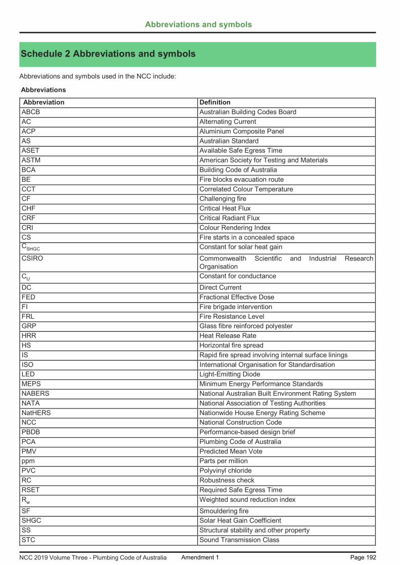
Schedule 2 Abbreviations and symbols
Abbreviations and symbols
Abbreviations and symbols used in the NCC include:
Abbreviations
Abbreviation Definition ABCB Australian Building Codes Board AC Alternating Current ACP Aluminium Composite Panel AS Australian Standard ASET Available Safe Egress Time ASTM American Society for Testing and Materials BCA Building Code of Australia BE Fire blocks evacuation route CCT Correlated Colour Temperature CF Challenging fire CHF Critical Heat Flux CRF Critical Radiant Flux CRI Colour Rendering Index CS Fire starts in a concealed space CSHGC Constant for solar heat gain CSIRO Commonwealth Scientific and Industrial Research
Organisation CU Constant for conductance DC Direct Current FED Fractional Effective Dose FI Fire brigade intervention FRL Fire Resistance Level GRP Glass fibre reinforced polyester HRR Heat Release Rate HS Horizontal fire spread IS Rapid fire spread involving internal surface linings ISO International Organisation for Standardisation LED Light-Emitting Diode MEPS Minimum Energy Performance Standards NABERS National Australian Built Environment Rating System NATA National Association of Testing Authorities NatHERS Nationwide House Energy Rating Scheme NCC National Construction Code PBDB Performance-based design brief PCA Plumbing Code of Australia PMV Predicted Mean Vote ppm Parts per million PVC Polyvinyl chloride RC Robustness check RSET Required Safe Egress Time Rw Weighted sound reduction index SF Smouldering fire SHGC Solar Heat Gain Coefficient SS Structural stability and other property STC Sound Transmission Class
NCC 2019 Volume Three - Plumbing Code of Australia Amendment 1 Page 192

Abbreviations and Symbols
NCC 2019 Volume Three - Plumbing Code of Australia
Symbols
Abbreviation DefinitionUF Unexpected catastrophic failureUPVC Unplasticized polyvinyl chlorideUT Fire in normally unoccupied room threatening occupants of
other roomsU-Value Thermal transmittanceVS Vertical fire spread involving external cladding or external
openings
Symbol Definition° degree(s)°C degree(s) Celsius°CDB degree(s) Celsius Dry Bulb°CWB degree(s) Celsius Wet Bulb-e/MJ equivalent per Megajoule(s)μm micrometredB(A) decibels “A” scale weighting networkJ Joule(s)J/kg.K Joules per kilogram degree KelvinJ/s.m2 Joules per second square metreK Kelvin(s)kg kilogram(s)kg/m kilogram(s) per metrekg/m2 kilogram(s) per square metrekg/m3 kilogram(s) per cubic metrekJ/m2.hour kilojoules per square metre hourkm kilometre(s)kPa kilopascal(s)kW/m2 kilowatt(s) per square metrekWheating kilowatt(s) of heatingkWr kilowatt(s) of refrigerationL litre(s)L/min litre(s) per minuteL/s litre(s) per secondL/s.m2 litre(s) per second square metreLumens/W Lumens per Wattlx luxm metre(s)m/s metre(s) per secondm2 square metre(s)m2.K/W square metre Kelvin(s) per Wattm3 cubic metre(s)m3/hour cubic metre(s) per hourm3/s cubic metre(s) per secondmcd/m2 millicandelas per square metremin minute(s)MJ/hour Megajoules per hourMJ/m2.annum Megajoules per square metre annummm millimetre(s)mm2 square millimetre(s)
Amendment 1 Page 193

Abbreviations and Symbols
NCC 2019 Volume Three - Plumbing Code of Australia
Symbol DefinitionMW megawatt(s)N newton(s)Pa pascal(s)Pa/m pascal(s) per metres second(s)V Volt(s)W Watt(s)Winput power Watts of input powerWr/Winput power Watts of thermal refrigeration per watt of input powerW/kWrej Watts per kilowatt of heat rejectedW/m.K Watts per metre degree KelvinW/m2 Watts per square metre°south degree south% percent> greater than< less than≤ less than or equal to≥ equal to or more than
Amendment 1 Page 194

Defined Terms
Schedule 3Defined Terms
Schedule 3 Definitions
NCC 2019 Volume Three - Plumbing Code of Australia
Schedule 3 Defined Terms
Amendment 1 Page 195

Defined Terms
NCC 2019 Volume Three - Plumbing Code of Australia
Schedule 3 Definitions Definitions
Schedule 3 Defined Terms
Amendment 1 Page 196

Defined Terms
NCC 2019 Volume Three - Plumbing Code of Australia
Definitions Note: States and Territories may vary or add to the definitions contained in Schedule 3 at the relevant State or Territory Appendix. In the NCC unless the contrary intention appears— Accessible means having features to enable use by people with a disability. Accessway means a continuous accessible path of travel (as defined in AS 1428.1) to, into or within a building.Accredited Testing Laboratory means—
(a) an organisation accredited by the National Association of Testing Authorities (NATA) to undertake the relevanttests; or
(b) an organisation outside Australia accredited to undertake the relevant tests by an authority recognised by NATAthrough a mutual recognition agreement; or
(c) an organisation recognised as being an Accredited Testing Laboratory under legislation at the time the test wasundertaken.
Activity support level means the degree to which occupants can undertake activities with respect to the likely activity traits and occupant traits.
Activity traits, for the purposes of Volume One, means the features of the activities that will be undertaken in a habitable room or space.
Activity traits, for the purposes of Volume Two, means the features of the activities that will be undertaken in a room or space.
Administering body means the body responsible for administering the WaterMark Certification Scheme.Aged care building means a Class 9c building for residential accommodation of aged persons who, due to varying
degrees of incapacity associated with the ageing process, are provided with personal care services and 24 hourstaff assistance to evacuate the building during an emergency.
Air-conditioning, for the purposes of Section J of Volume One, means a service that actively cools or heats the air withina space, but does not include a service that directly
(a) cools or heats cold or hot rooms; or(b) maintains specialised conditions for equipment or processes, where this is the main purpose of the service.
Alarm zone, for the purposes of Specification E2.2d of Volume One, means an area of a building protected by one or more smoke alarms connected to one alarm circuit.
Alpine area means an area given in Figure 1 and in Table 1 for specific locations, and is— (a) likely to be subject to significant snowfalls; and(b) in New South Wales, A.C.T. or Victoria more than 1200 m above the Australian Height Datum; and(c) in Tasmania more than 900 m above the Australian Height Datum.
Schedule 3 Definitions
Explanatory information: This term is used to articulate whether the height of a room or space is sufficient and by what degree. This is achieved by having regard to the room or space’s intended use by occupants, through consideration of the defined terms ‘activity traits‘ and ‘occupant traits‘.
Explanatory information: This term is used to describe the characteristics of the activities that will be undertaken in a room or space. For example, the activities likely to be undertaken in a bedroom, and the associated features are—
sleeping — a person laying horizontally; and•resting — a person laying horizontally or sitting upright on the bed; and•leisure activities, such as reading a book — a person sitting upright on the bed, with enough space to•stretch their arms vertically; anddressing/changing clothes — a person standing with enough space to stretch their arms vertically.•
Amendment 1 Page 197

Defined Terms
NCC 2019 Volume Three - Plumbing Code of Australia
Figure 1 Alpine areas
Table 1 Alpine areas where snow loads are significant
Note: This map is approximate only and altitude above Australian Height Datum must be used to determine whether the building falls into an alpine area region.
Location Map identifierKiandra (NSW) 1Mount Kosciuszko (NSW) 2Perisher Valley (NSW) 3Thredbo (NSW) 4Cabramurra (NSW) 5Charlotte Pass Village (NSW) 6Diggers Creek (NSW) 7
Amendment 1 Page 198

Explanatory information: Alpine areas are located in New South Wales, Victoria and Tasmania. Alpine areas are areas 1200 m or more above Australian Height Datum (AHD) for New South Wales, Australian Capital Territory and Victoria, and 900 m or more above AHD for Tasmania, as shown in Figure 1. Alpine areas are considered to receive significant snowfalls (snowfalls that result in an average snow accumulation on the ground of 175 mm or greater). Regions in New South Wales, the Australian Capital Territory and Victoria between 600–1200 m AHD are considered to be sub-alpine areas and may receive significant snowfalls, however unlike alpine areas the snow is unlikely to accumulate. It is recommended that the appropriate authority be consulted to determine whether the building is located in an alpine area. AS/NZS 1170.3 also contains further detail in the identification of alpine areas and the altitude of the alpine regions of Australia. In the Australian Capital Territory, Canberra is not designated as an alpine area as snow loads are not considered significant.
State and Territory variations For Volume One see (NSW, Appropriate authority) For Volume Two see (NSW, Appropriate authority)
Location Map identifier Guthega Village (NSW) 8 Mount Blue Cow (NSW) 9 Mount Selwyn (NSW) 10 Perisher Range (NSW) 11 Rules Point (NSW) 12 Sawpit Creek (NSW) 13 Smiggin Holes (NSW) 14 Smiggin Range (NSW) 15 Three Mile Dam (NSW) 16 Wilsons Valley (NSW) 17 Falls Creek (Vic.), including Summit Area, Sun Valley and Village Bowl 18 Mount Baw Baw (Vic.) 19 Mount Buffalo (Vic.), including Chalet, Dingo Dell and Tatra 20 Mount Buller (Vic.), including Baldy and Village 21 Mount Hotham (Vic.), including Davenport and Village Centre 22 Dinner Plain (Vic.) 23 Lake Mountain (Vic.) 24 Mount Stirling (Vic.) 25 Ben Lomond Ski Field (Tas.) 26 Cradle Valley (Tas.) 27 Great Lake Area (Tas.) 28 Mount Field Ski Field (Tas.) 29
Appropriate Authority, for the purposes of Schedule 7, means the relevant authority with the statutory responsibility to determine the particular matter satisfies the relevant Performance Requirement.
Defined Terms
NCC 2019 Volume Three - Plumbing Code of Australia Amendment 1 Page 199
Alteration in relation to a building, includes an addition or extension to a building.Aluminium Composite Panel (ACP) means flat or profiled aluminium sheet material in composite with any type of
materials.Amenity means an attribute which contributes to the health, physical independence, comfort and well-being of people. Ancillary element means an element that is secondary to and not an integral part of another element to which it is
attached. Annual greenhouse gas emissions means the theoretical amount of greenhouse gas emissions attributable to the
energy used annually by a building’s services, excluding kitchen exhaust and the like. Appropriate authority means the relevant authority with the statutory responsibility to determine the particular matter.

State and Territory variation For Volume One see (NSW, Assembly building) and (SA, Assembly building)
Appropriately qualified person means a person recognised by the appropriate authority as having qualifications and/or experience in the relevant discipline in question.
Approved disposal system means a system for the disposal of sewage, sullage or stormwater approved by an authority having jurisdiction.
Articulated masonry means masonry construction in which special provisions have been made for movement by articulation.
Assembly building means a building where people may assemble for— (a) civic, theatrical, social, political or religious purposes including a library, theatre, public hall or place of worship;
or(b) educational purposes in a school, early childhood centre, preschool, or the like; or(c) entertainment, recreational or sporting purposes including—
(i) a discotheque, nightclub or a bar area of a hotel or motel providing live entertainment or containing a dancefloor; or
(ii) a cinema; or(iii) a sports stadium, sporting or other club; or
(d) transit purposes including a bus station, railway station, airport or ferry terminal.
Assessment Method means a method that can be used for determining that a Performance Solution or Deemed-to- Satisfy Solution complies with the Performance Requirements.
Atrium means a space within a building that connects 2 or more storeys and— (a) is enclosed at the top by a floor or roof (including a glazed roof structure); and(b) includes any adjacent part of the building not separated by an appropriate barrier to fire; but(c) does not include a stairwell, rampwell or the space within a shaft; and(d) for the purposes of (a) a space is considered enclosed if the area of the enclosing floor or roof is greater than
50% of the area of the space, measured in plan, of any of the storeys connected by the space.
Atrium well means a space in an atrium bounded by the perimeter of the openings in the floors or by the perimeter of the floors and the external walls.
Automatic means designed to operate when activated by a heat, smoke or fire sensing device. Available safe egress time (ASET) means the time between ignition of a fire and the onset of untenable conditions in a
specific part of a building. This is the calculated interval between the time of ignition of a fire and the time at which conditions become such that the occupant is unable to take effective action to escape to a place of safety.
Average daylight factor means the ratio of the illumination level within a room provided by daylight to the level of daylight outside the building during overcast conditions.
Average recurrence interval, applied to rainfall, means the expected or average interval between exceedances for a 5 minute duration rainfall intensity.
Average specific extinction area means the average specific extinction area for smoke as determined by AS 5637.1. Backflow prevention device means an air gap, break tank or mechanical device that is designed to prevent the unplanned
reversal of flow of water or contaminants into the water service or a Network Utility Operator’s water supply. Backpressure means a reversal of water flow caused by the downstream pressure becoming greater than the supply
pressure. Backsiphonage means a reversal of flow of water caused by negative pressure in the distributing pipes of a water service
or supply. Backstage means a space associated with, and adjacent to, a stage in a Class 9b building for scenery, props, equipment,
dressing rooms, or the like. Battery system means one or more chemical cells connected in series, parallel or a combination of the two for the purpose
of electrical energy storage. Blockage means an obstruction within a drainage system.
The Appropriate Authority is typically the building surveyor or building certifier charged with the statutory responsibility to determine building compliance and issue the building permit / approval and occupancy certificate / approval.
Explanatory information:
Defined Terms
NCC 2019 Volume Three - Plumbing Code of Australia
Boiler means a vessel or an arrangement of vessels and interconnecting parts, wherein steam or other vapour is
Amendment 1 Page 200

Explanatory information: Breaking surf normally occurs in areas exposed to the open sea. Breaking surf does not normally occur in sheltered areas, such as that which occurs around Port Phillip Bay, Sydney Harbour, Swan River, Derwent River and similar locations.
generated, or water or other liquid is heated at a pressure above that of the atmosphere, by the application of fire, the products of combustion, electrical power, or similar high temperature means, and—
(a) includes superheaters, reheaters, economisers, boiler piping, supports, mountings, valves, gauges, fittings,controls, the boiler settings and directly associated equipment; but
(b) excludes a fully flooded or pressurised system where water or other liquid is heated to a temperature lowerthan the normal atmospheric boiling temperature of the liquid.
Breaking surf means any area of salt water in which waves break on an average of at least 4 days per week but does not include white caps or choppy water.
Burnout means exposure to fire for a time that includes fire growth, full development, and decay in the absence of intervention or automatic suppression, beyond which the fire is no longer a threat to building elements intended to perform loadbearing or fire separation functions, or both.
Defined Terms
NCC 2019 Volume Three - Plumbing Code of Australia
Carpark means a building that is used for the parking of motor vehicles but is neither a private garage nor used for the servicing of vehicles, other than washing, cleaning or polishing. Cavity means a void between 2 leaves of masonry, or in masonry veneer construction, a void between a leaf of masonry
and the supporting frame. Cavity wall, for the purposes of FV1.1 in Volume One and V2.2.1 in Volume Two, means a wall that incorporates a drained
cavity. Certificate of Accreditation means a certificate issued by a State or Territory accreditation authority stating that the
properties and performance of a building material or method of construction or design fulfil specific requirements of the BCA.
Certificate of Conformity means a certificate issued under the ABCB scheme for products and systems certification stating that the properties and performance of a building material or method of construction or design fulfil specific requirements of the NCC.
Certification body means a person or organisation operating in the field of material, product, form of construction or design certification that has been accredited by the Joint Accreditation System of Australia and New Zealand (JAZ- ANZ), and is accredited for a purpose other than as part of the CodeMark Australia Certification Scheme or WaterMark Certification Scheme.
Characteristic means the occupant data to be used in the modelling of access solutions which define how an occupant interacts with a building, i.e. occupant movement speeds, turning ability, reach capability, perception of luminance contrast and hearing threshold.
Clad frame means timber or metal frame construction with exterior timber or sheet wall cladding that is not sensitive to minor movement and includes substructure masonry walls up to 1.5 m high.
Climate zone means an area defined in Figure 2 and in Table 2 for specific locations, having energy efficiency provisions based on a range of similar climatic characteristics.
Amendment 1 Page 201

Defined Terms
NCC 2019 Volume Three - Plumbing Code of Australia
Figure 2 Climate zones for thermal design
Table 2 Climate zones for thermal design—Various locations
Notes:
1. This map can be viewed in enlargeable form on the ABCB website at www.abcb.gov.au.2. A Zone 4 area in South Australia, other than a council area, at an altitude greater than 300 m above the Australian
Height Datum is to be considered as Zone 5.These areas have been defined in an enlarged format on the following maps produced by the Department ofPlanning, Transport and Infrastructure:Adelaide Hills Council Climate Zone MapBarossa Council Climate Zone MapRegional Council of Goyder Climate Zone MapThese maps can be viewed on the Government of South Australia website at www.sa.gov.au.
3. Locations in climate zone 8 are in alpine areas.
Location Climate zone
Location Climate zone
Location Climate zone
Location Climate zone
Australian Capital Territory Canberra 7New South Wales Albury 4 Byron Bay 2 Lord Howe
Island2 Sydney West 6
Armidale 7 Cobar 4 Moree 4 Tamworth 4Batemans Bay
6 Coffs Harbour 2 Newcastle 5 Thredbo 8
Bathurst 7 Dubbo 4 Nowra 6 Wagga Wagga 4Bega 6 Goulburn 7 Orange 7 Williamtown 5Bellingen Shire - Dorrigo Plateau
7 Grafton 2 Perisher Smiggins
8 Wollongong 5
Amendment 1 Page 202

Defined Terms
NCC 2019 Volume Three - Plumbing Code of Australia
Combustible means— (a) applied to a material — combustible as determined by AS 1530.1; and(b) applied to construction or part of a building — constructed wholly or in part of combustible materials.
Common wall, for the purposes of Volume One, means a wall that is common to adjoining buildings. Common wall, for the purposes of Volume Two, means a wall that is common to adjoining buildings other than Class 1
buildings. Condensation means the formation of moisture on the surface of a building element or material as a result of moist air
Location Climate zone
Location Climate zone
Location Climate zone
Location Climate zone
Bellingen Shire - Valley & seaboard
2 Griffith 4 Port Macquarie 5 Yass 6
Bourke 4 Ivanhoe 4 Sydney East 5Broken Hill 4 Lismore 2Northern TerritoryAlice Springs 3 Elliot 3 Renner Springs 3Darwin 1 Katherine 1 Tennant Creek 3Queensland Birdsville 3 Gladstone 2 Mount Isa 3Brisbane 2 Hervey Bay 2 Normanton 1 Townsville 1Bundaberg 2 Hughenden 3 Rockhampton 2 Warwick 5Cairns 1 Longreach 3 Roma 3 Weipa 1Cooktown 1 Mackay 2 Southport 2Cunnamulla 3 Toowoomba 5South Australia Adelaide 5 Kingscote 6 Marree 4 Port Lincoln 5Bordertown 6 Leigh Creek 5 Mount Gambier 6 Renmark 5Ceduna 5 Lobethal 6 Murray Bridge 6 Tarcoola 4Cook 4 Loxton 5 Oodnadatta 4 Victor Harbour 6Elliston 5 Naracoorte 6 Port Augusta 4 Whyalla 4Tasmania Burnie 7 Flinders Island 7 Launceston 7 Rossarden 7Bicheno 7 Hobart 7 New Norfolk 7 Smithton 7Deloraine 7 Huonville 7 Oatlands 7 St Marys 7Devonport 7 King Island 7 Orford 7 Zeehan 7Victoria Anglesea 6 Bright 7 Horsham 6 Swan Hill 4Ararat 7 Colac 6 Melbourne 6 Traralgon 6Bairnsdale 6 Dandenong 6 Mildura 4 Wangaratta 7Ballarat 7 Echuca 4 Portland 6 Warrnambool 6Benalla 6 Geelong 6 Sale 6 Wodonga 6Bendigo 6 Hamilton 7 Shepparton 4Western Australia Albany 6 Cocos Island 1 Kalgoorlie-
Boulder4 Port Hedland 1
Balladonia 4 Derby 1 Karratha 1 Wagin 4Broome 1 Esperance 5 Meekatharra 4 Wyndham 1Bunbury 5 Exmouth 1 Northam 4Carnarvon 3 Geraldton 5 Pemberton 6Christmas Island
1 Halls Creek 3 Perth 5
Amendment 1 Page 203

Defined Terms
NCC 2019 Volume Three - Plumbing Code of Australia
coming into contact with a surface which is at a lower temperature. Conditioned space, for the purposes of Volume One, means a space within a building, including a ceiling or under-floor
supply air plenum or return air plenum, where the environment is likely, by the intended use of the space, to have its temperature controlled by air-conditioning.
Conditioned space, for the purposes of Volume Two, means a space within a building that is heated or cooled by the building’s domestic services, excluding a non-habitable room in which a heater with a capacity of not more than 1.2kW or 4.3 MJ/hour is installed.
Containment protection means the installation of a backflow prevention device at the point of connection of a Network Utility Operator’s water supply to a site.
Contaminant means any substance (including gases, liquids, solids or micro-organisms), energy (excluding noise) or heat, that either by itself or in combination with the same, similar or other substances, energy or heat, changes or is likely to change the physical, chemical or biological condition of water.
Construction activity actions means actions due to stacking of building materials or the use of equipment, including cranes and trucks, during construction or actions which may be induced by floor to floor propping.
Controlled fill means material that has been placed and compacted in layers with compaction equipment (such as a vibrating plate) within a defined moisture range to a defined density requirement.
Cooling load means the calculated amount of energy removed from the cooled spaces of the building annually by artificial means to maintain the desired temperatures in those spaces.
Critical radiant flux (CRF) means the critical heat flux at extinguishment (CHF in kW/m2) as determined by AS ISO 9239.1.
Cross-connection means any actual or potential connection between a water supply and any contaminant.Curtain wall means a non-loadbearing external wall that is not a panel wall.Damp-proof course (DPC) means a continuous layer of impervious material placed in a masonry wall or pier, or between
a wall or pier and a floor, to prevent the upward or downward migration of water. Deemed-to-Satisfy Provisions means provisions which are deemed to satisfy the Performance Requirements. Deemed-to-Satisfy Solution means a method of satisfying the Deemed-to-Satisfy Provisions.Defined flood event (DFE) means the flood event selected for the management of flood hazard for the location of specific
development as determined by the appropriate authority.Defined flood level (DFL) means the flood level associated with a defined flood event relative to a specified datum (see
Figure 3).
Figure 3 Identification of defined flood level, flood hazard level and freeboard
Design fire means the quantitative description of a representation of a fire within the design scenario.
Amendment 1 Page 204

Defined Terms
NCC 2019 Volume Three - Plumbing Code of Australia
Design scenario means the specific scenario of which the sequence of events is quantified and a fire safety engineeringanalysis is conducted against.
Design wind speed means the design gust wind speed for the area where the building is located, calculated in accordance with AS/NZS 1170.2 or AS 4055 (see Table 3 for wind classes).
Table 3 Wind classes
Designated bushfire prone area means land which has been designated under a power of legislation as being subject, or likely to be subject, to bushfires.
Detention centre means a building in which persons are securely detained by means of the built structure including a prison, remand centre, juvenile detention centre, holding cells or psychiatric detention centre.
Direct fix cladding wall, for the purposes of FV1.1 in Volume One and V2.2.1 in Volume Two, means a wall with cladding attached directly to the wall framing without the use of a drained cavity.
Discontinuous construction means the following: (a) A wall having a minimum 20 mm cavity between 2 separate leaves, and—
(i) for masonry, where wall ties are used to connect leaves, the ties are of the resilient type; and(ii) for other than masonry, there is no mechanical linkage between the leaves, except at the periphery.
(b) A staggered stud wall is not deemed to be discontinuous construction.
Display glazing means glazing used to display retail goods in a shop or showroom directly adjacent to a walkway orfootpath, but not including that used in a café or restaurant.
Domestic services means the basic engineering systems that use energy or control the use of energy; and— (a) includes—
(i) heating, air-conditioning, mechanical ventilation and artificial lighting; and(ii) pumps and heaters for swimming pools and spa pools; and(iii) heated water systems; but
(b) excludes cooking facilities and portable appliances.
Drainage means any sanitary drainage, liquid trade waste drainage or stormwater drainage system.Drinking water means water intended primarily for human consumption but which has other domestic uses.
Early childhood centre means any premises or part thereof providing or intending to provide a centre-based education and care service within the meaning of the Education and Care Services National Law Act 2010 (Vic), the Education and Care Services National Regulations and centre-based services that are licensed or approved under State and Territory children’s services law, but excludes education and care primarily provided to school aged children in outside school hours settings.
Non-cyclonic Region A and B Cyclonic Region C and DN1, N2, N3 C1N4, N5, N6 (these wind classes are covered by Volume Two Part 3.0, Structural provisions).
C2, C3, C4 (these wind classes are covered by Volume Two Part 3.0, Structural provisions).
Notes:
1. Wind classification map identifying wind regions is contained in Volume Two Part 3.0 (see Figure 3.0.1).2. Information on wind classes for particular areas may be available from the appropriate authority.3. “N” = non-cyclonic winds and “C” = cyclonic winds.
State and Territory variations For Volume One see (NSW, Designated bushfire prone area)For Volume Two see (NSW, Designated bushfire prone area)
Explanatory Information: See also the Australian Drinking Water Guidelines produced by the National Health and Medical Research Council.
State and Territory variations For Volume One see (Tas, Early childhood centre) and (Vic, Early childhood centre)
Amendment 1 Page 205

Defined Terms
NCC 2019 Volume Three - Plumbing Code of Australia
Effective height means the vertical distance between the floor of the lowest storey included in the calculation of rise in storeys and the floor of the topmost storey (excluding the topmost storey if it contains only heating, ventilating, lift orother equipment, water tanks or similar service units).
Electric passenger lift means a power-operated lift for raising or lowering people in a car in which the motion of the car is obtained from an electric motor mechanically coupled to the hoisting mechanism.
Electricity network substation means a building in which high voltage supply is converted or transformed and which is controlled by a licensed network service provider designated under a power of legislation.
Electrohydraulic passenger lift means a power-operated lift for raising or lowering people in a car in which the motion of the car is obtained from the action of liquid under pressure acting on a piston or ram, the pressure being generated by a pump driven by an individual electric motor.
Envelope, for the purposes of Section J in Volume One, means the parts of a building’s fabric that separate a conditioned space or habitable room from—
(a) the exterior of the building; or(b) a non-conditioned space including—
(i) the floor of a rooftop plant room, lift-machine room or the like; and(ii) the floor above a carpark or warehouse; and(iii) the common wall with a carpark, warehouse or the like.
Envelope, for the purposes of Part 2.6 and Part 3.12 in Volume Two, means the parts of a building’s fabric that separateartificially heated or cooled spaces from—
(a) the exterior of the building; or(b) other spaces that are not artificially heated or cooled.
Equivalent means equivalent to the level of health, safety and amenity provided by the Deemed-to-Satisfy Provisions.Evacuation route means the continuous path of travel (including exits, public corridors and the like) from any part of a
building, including within a sole-occupancy unit in a Class 2 or 3 building or Class 4 part, to a safe place.Evacuation time means the time calculated from when the emergency starts for the occupants of the building to evacuate
to a safe place.Exit means—
(a) any, or any combination of the following if they provide egress to a road or open space:(i) An internal or external stairway.(ii) A ramp.(iii) A fire-isolated passageway.(iv) A doorway opening to a road or open space.
(b) A horizontal exit or a fire-isolated passageway leading to a horizontal exit.
Expert Judgement means the judgement of an expert who has the qualifications and experience to determine whether a Performance Solution or Deemed-to-Satisfy Solution complies with the Performance Requirements.
External wall, for the purposes of Volume One, means an outer wall of a building which is not a common wall.External wall, for the purposes of Volume Two, means an outer wall of a building which is not a separating wall.Extra-low voltage means a voltage not exceeding 50 V AC or 120 V ripple-free DC.Fabric means the basic building structural elements and components of a building including the roof, ceilings, walls,
glazing and floors. Farming means—
(a) cultivating, propagating and harvesting plants or fungi or their products or parts, including seeds, spores, bulbs
Explanatory Information: Contemporary and relevant qualifications and/or experience are necessary to determine whether a Performance Solution complies with the Performance Requirements. The level of qualification and/or experience may differ dependingon the complexity of the proposal and the requirements of the regulatory authority. Practitioners should seek advice from the authority having jurisdiction or appropriate authority for clarification as to what will be accepted.
State and Territory variation: For Volume Three see (Tas, Expert Judgement)
Amendment 1 Page 206

Defined Terms
NCC 2019 Volume Three - Plumbing Code of Australia
or the like, but does not include forestry; or (b) maintaining animals in any physical environment for the purposes of—
(i) breeding them; or(ii) selling them; or(iii) acquiring and selling their bodily produce such as milk, wool, eggs or the like; or
(c) a combination of (a), and (b),but does not include forestry or maintaining animals for sport or recreational purposes.
Farm building means a Class 7 or 8 building located on land primarily used for farming—(a) that is—
(i) used in connection with farming; or(ii) used primarily to store one or more farm vehicles; or(iii) a combination of (i) and (ii); and
(b) in which the total number of persons accommodated at any time does not exceed one person per 200 m2 offloor area or part thereof, up to a maximum of 8 persons; and
(c) with a total floor area of not more than 3500 m2.
Farm shed means a single storey Class 7 or 8 building located on land primarily used for farming—(a) that is—
(i) used in connection with farming; or(ii) used primarily to store one or more farm vehicles; or(iii) a combination of (i) and (ii); and
(b) occupied neither frequently nor for extended periods by people; and(c) in which the total number of persons accommodated at any time does not exceed 2; and(d) with a total floor area of more than 500 m2 but not more than 2000 m2.
Farm vehicle means a vehicle used in connection with farming.Finished ground level, for the purposes of Part 3.2 in Volume Two, means the ground level adjacent to footing systems
at the completion of construction and landscaping. Fire brigade means a statutory authority constituted under an Act of Parliament having as one of its functions, the
protection of life and property from fire and other emergencies. Fire brigade station for the purposes of E1.3(a)(ii) and H3.9 in Volume One, means a state or territory government
operated premises which is a station for a fire brigade.Fire compartment means—
(a) the total space of a building; or(b) when referred to in—
(i) the Performance Requirements — any part of a building separated from the remainder by barriers to firesuch as walls and/or floors having an appropriate resistance to the spread of fire with any openingsadequately protected; or
(ii) the Deemed-to-Satisfy Provisions — any part of a building separated from the remainder by walls and/orfloors each having an FRL not less than that required for a fire wall for that type of construction and whereall openings in the separating construction are protected in accordance with the Deemed-to-SatisfyProvisions of the relevant Part.
Fire growth means the stage of fire development during which the heat release rate and the temperature of the fire aregenerally increasing.
Fire hazard means the danger in terms of potential harm and degree of exposure arising from the start and spread of fire and the smoke and gases that are thereby generated.
Fire hazard properties means the following properties of a material or assembly that indicate how they behave under specific fire test conditions:
State and Territory variationFor Volume One see (SA, Farm building)
Amendment 1 Page 207

Defined Terms
NCC 2019 Volume Three - Plumbing Code of Australia
(a) Average specific extinction area, critical radiant flux and Flammability Index, determined as defined in Schedule3.
(b) Smoke-Developed Index, smoke development rate and Spread-of-Flame Index, determined in accordance withSchedule 6.
(c) Group number and smoke growth rate index (SMOGRARC), determined in accordance with Specification C1.10of Volume One.
Fire intensity means the rate of release of calorific energy in watts, determined either theoretically or empirically, as applicable.
Fire-isolated passageway means a corridor, hallway or the like, of fire-resisting construction, which provides egress toor from a fire-isolated stairway or fire-isolated ramp or to a road or open space.
Fire-isolated ramp means a ramp within a fire-resisting enclosure which provides egress from a storey.Fire-isolated stairway means a stairway within a fire-resisting shaft and includes the floor and roof or top enclosing
structure. Fire load means the sum of the net calorific values of the combustible contents which can reasonably be expected to
burn within a fire compartment, including furnishings, built-in and removable materials, and building elements. Thecalorific values must be determined at the ambient moisture content or humidity. (The unit of measurement is MJ.)
Fire-protected timber means fire-resisting timber building elements that comply with Volume One Specification C1.13a.Fire-protective covering means—
(a) 13 mm fire-protective grade plasterboard; or(b) 12 mm cellulose cement flat sheeting complying with AS/NZS 2908.2 or ISO 8336; or(c) 12 mm fibrous plaster reinforced with 13 mm x 13 mm x 0.7 mm galvanised steel wire mesh located not more
than 6 mm from the exposed face; or(d) other material not less fire-protective than 13 mm fire-protective grade plasterboard, fixed in accordance with
the normal trade practice for a fire-protective covering.
Fire-resistance level (FRL) means the grading periods in minutes determined in accordance with Schedule 5, for the following criteria—
(a) structural adequacy; and(b) integrity; and(c) insulation,and expressed in that order.
Fire-resisting, for the purposes of Volume One, applied to a building element, means having an FRL appropriate for that element.
Fire-resisting, for the purposes of Volume Two, applied to a structural member or other part of a building, means havingthe FRL required for that structural member or other part.
Fire-resisting construction, for the purposes of Volume One, means one of the Types of construction referred to in Part C1 of Volume One.
Fire safety engineering means application of engineering principles, rules and expert judgement based on a scientificappreciation of the fire phenomenon, often using specific design scenarios, of the effects of fire and of the reactionand behaviour of people in order to—
(a) save life, protect property and preserve the environment and heritage from destructive fire; and(b) quantify the hazards and risk of fire and its effects; and(c) mitigate fire damage by proper design, construction, arrangement and use of buildings, materials, structures,
industrial processes and transportation systems; and(d) evaluate analytically the optimum protective and preventive measures, including design, installation and
maintenance of active and passive fire and life safety systems, necessary to limit, within prescribed levels, theconsequences of fire.
Fire safety system means one or any combination of the methods used in a building to
Note: A dash means that there is no requirement for that criterion. For example, 90/–/– means there is no requirement for an FRL for integrity and insulation, and –/–/– means there is no requirement for an FRL.
Amendment 1 Page 208

Defined Terms
NCC 2019 Volume Three - Plumbing Code of Australia
(a) warn people of an emergency; or(b) provide for safe evacuation; or(c) restrict the spread of fire; or(d) extinguish a fire,and includes both active and passive systems.
Fire-source feature means— (a) the far boundary of a road, river, lake or the like adjoining the allotment; or(b) a side or rear boundary of the allotment; or(c) an external wall of another building on the allotment which is not a Class 10 building.
Fire wall means a wall with an appropriate resistance to the spread of fire that divides a storey or building into fire compartments.
Fixed wired, for the purposes of Specification E2.2d in Volume One, means a system of electrical wiring (either AC or DC), in which cables are fixed or supported in position.
Flammability Index means the index number as determined by AS 1530.2. Flashing means a strip or sleeve of impervious material dressed, fitted or built-in to provide a barrier to moisture
movement, or to divert the travel of moisture, or to cover a joint where water would otherwise penetrate to the interior of a building.
Flashover, in relation to fire hazard properties, means a heat release rate of 1 MW.Flight means that part of a stair that has a continuous series of risers, including risers of winders, not interrupted by a
landing or floor (for Volume Two, see Figure 4).
Explanatory information for Volume Two: A flight is the part of a stair that has a continuous slope created by the nosing line of treads. The length of a flight islimited to restrict the distance a person could fall down a stair. Quarter landings, as shown in Figure 4, are consideredsufficient to halt a person’s fall and therefore are considered for the purposes of Volume Two not to be part of the flight.
Amendment 1 Page 209

Defined Terms
NCC 2019 Volume Three - Plumbing Code of Australia
Flood hazard area means the site (whether or not mapped) encompassing land lower than the flood hazard level whichhas been determined by the appropriate authority.
Flood hazard level (FHL) means the flood level used to determine the height of floors in a building and represents the defined flood level plus the freeboard (see Figure 3).
Floor area, for the purposes of Volume One, means— (a) in relation to a building — the total area of all storeys; and(b) in relation to a storey — the area of all floors of that storey measured over the enclosing walls, and includes—
(i) the area of a mezzanine within the storey, measured within the finished surfaces of any external walls;and
(ii) the area occupied by any internal wall or partitions, any cupboard, or other built-in furniture, fixture or fitting;and
(iii) if there is no enclosing wall, an area which has a use that—(A) contributes to the fire load; or(B) impacts on the safety, health or amenity of the occupants in relation to the provisions of the BCA; and
(c) in relation to a room — the area of the room measured within the finished surfaces of the walls, and includesthe area occupied by any cupboard or other built-in furniture, fixture or fitting; and
(d) in relation to a fire compartment — the total area of all floors within the fire compartment measured within thefinished surfaces of the bounding construction, and if there is no bounding construction, includes an area whichhas a use which contributes to the fire load; and
(e) in relation to an atrium — the total area of all floors within the atrium measured within the finished surfaces ofthe bounding construction and if no bounding construction, within the external walls.
Figure 4 Identification of stair flights — Plan view
State and Territory variations For Volume One see (Vic, Flood hazard area)For Volume Two see (Vic, Flood hazard area)
Amendment 1 Page 210

Defined Terms
NCC 2019 Volume Three - Plumbing Code of Australia
Floor area, for the purposes of Volume Two, means in relation to a room, the area of the room measured within the finished surfaces of the walls, and includes the area occupied by any cupboard or other built-in furniture, fixture or fitting (see Figure 5).
Figure 5 Identification of floor area of a room
Foundation means the ground which supports the building (see Figure 6).
Figure 6 Identification of foundation
Fractional effective dose (FED) means the fraction of the dose (of thermal effects) that would render a person of average susceptibility incapable of escape.
Freeboard means the height above the defined flood level as determined by the appropriate authority, used to compensatefor effects such as wave action and localised hydraulic behaviour.
Fully developed fire means the state of total involvement of the majority of available combustible materials in a fire. Glazing, for the purposes of Section J in Volume One, means a transparent or translucent element and its supporting
frame located in the envelope, and includes a window other than a roof light.Glazing, for the purposes of Part 2.6 and Part 3.12 in Volume Two, means a transparent or translucent element and its
supporting frame located in the external fabric of the building, and includes a window other than a roof light.Green Star means the building sustainability rating scheme managed by the Green Building Council of Australia. Going means the horizontal dimension from the front to the back of a tread less any overhang from the next tread or
landing above (see Figure 3.9.1.4).Group number means the number of one of 4 groups of materials used in the regulation of fire hazard properties and
Explanatory information: The definition for FED has been modified from the ISO definition to be made specific for Schedule 7. The use of COor CO2 as part of FED is not part of that Verification Method. This is because the ability to measure CO in a repeatabletest varies by two orders of magnitude for common cellulosic fuel.
State and Territory variations For Volume One see (Vic, Freeboard)For Volume Two see (Vic, Freeboard)
Amendment 1 Page 211

Defined Terms
NCC 2019 Volume Three - Plumbing Code of Australia
applied to materials used as a finish, surface, lining, or attachment to a wall or ceiling. Habitable room means a room used for normal domestic activities, and—
(a) includes a bedroom, living room, lounge room, music room, television room, kitchen, dining room, sewing room,study, playroom, family room, home theatre and sunroom; but
(b) excludes a bathroom, laundry, water closet, pantry, walk-in wardrobe, corridor, hallway, lobby, photographicdarkroom, clothes-drying room, and other spaces of a specialised nature occupied neither frequently nor forextended periods.
Hazard Rating means a rating of either Low Hazard, Medium Hazard or High Hazard determined in accordance withSpecification B5.1 in Volume Three, for any Deemed-to-Satisfy Solution.
Health-care building means a building whose occupants or patients undergoing medical treatment generally need physical assistance to evacuate the building during an emergency and includes—
(a) a public or private hospital; or(b) a nursing home or similar facility for sick or disabled persons needing full-time care; or(c) a clinic, day surgery or procedure unit where the effects of the predominant treatment administered involve
patients becoming non-ambulatory and requiring supervised medical care on the premises for some time afterthe treatment.
Heated water means water that has been intentionally heated. It is normally referred to as hot water or warm water. Heating load means the calculated amount of energy delivered to the heated spaces of the building annually by artificial
means to maintain the desired temperatures in those spaces. Heat release means the thermal energy produced by combustion (kJ). Heat release rate (HRR) means the rate of thermal energy production generated by combustion (kW (preferred) or MW). High Hazard means any condition, device or practice which, in connection with a water supply, has the potential to cause
death. High wind area means a region that is subject to design wind speed more than N3 or C1 (see Table 3).Horizontal exit means a required doorway between 2 parts of a building separated from each other by a fire wall. Hours of operation means the number of hours when the occupancy of the building is greater than 20% of the peak
occupancy. House energy rating software, for the purposes of Volume One, means software accredited under the Nationwide House
Energy Rating Scheme. House energy rating software, for the purposes of Volume Two—
(a) applied to V2.6.2.2—means software accredited or previously accredited under the Nationwide House EnergyRating Scheme and the additional functionality provided in non-regulatory mode; and
(b) applied to 3.12.0.1—means software accredited under the Nationwide House Energy Rating Scheme.
Housing Provisions means the requirements for Class 1 and 10 buildings contained in Volume Two of the National Construction Code as published by the Australian Building Codes Board.
Illuminance means the luminous flux falling onto a unit area of surface. Illumination power density (W/m2) means the total of the power that will be consumed by the lights in a space, including
any lamps, ballasts, current regulators and control devices other than those that are plugged into socket outlets for intermittent use such as floor standing lamps, desk lamps or work station lamps, divided by the area of the space.
Inclined lift means a power-operated device for raising or lowering people within a carriage that has one or more rigid
Explanatory information: The Nationwide House Energy Rating Scheme (NatHERS) refers to the Australian governments’ scheme that facilitates consistent energy ratings from software tools which are used to assess the potential thermal efficiency of dwelling envelopes.
Explanatory information:
Illumination power density relates to the power consumed by the lighting system and includes the•light source or luminaire and any control device. The power for the lighting system is the illuminationpower load. This approach is more complicated than the lamp power density approach but providesmore flexibility for a dwelling with sophisticated control systems.The area of the space refers to the area the lights serve. This could be considered a single room,•open plan space, verandah, balcony or the like, or the total area of all these spaces.
Amendment 1 Page 212

Defined Terms
NCC 2019 Volume Three - Plumbing Code of Australia
guides on an inclined plane. Individual protection means the installation of a backflow prevention device at the point where a water service connects
to a single fixture or appliance. Insulation, in relation to an FRL, means the ability to maintain a temperature on the surface not exposed to the furnace
below the limits specified in AS 1530.4. Integrity, in relation to an FRL, means the ability to resist the passage of flames and hot gases specified in AS 1530.4. Internal wall, for the purposes of Volume One, excludes a common wall or a party wall.Internal wall, for the purposes of Volume Two, excludes a separating wall, common wall or party wall.Interstitial condensation means the condensation of moisture on surfaces between material layers inside the building
component. JAS-ANZ means the Joint Accreditation System of Australia and New Zealand. Lamp power density (W/m2) means the total of the maximum power rating of the lamps in a space, other than those that
are plugged into socket outlets for intermittent use such as floor standing lamps, desk lamps or work station lamps, divided by the area of the space.
Landing means an area at the top or bottom of a flight or between two flights.Latent heat gain means the heat gained by the vapourising of liquid without change of temperature. Lightweight construction means construction which incorporates or comprises—
(a) sheet or board material, plaster, render, sprayed application, or other material similarly susceptible to damageby impact, pressure or abrasion; or
(b) concrete and concrete products containing pumice, perlite, vermiculite, or other soft material similarly susceptibleto damage by impact, pressure or abrasion; or
(c) masonry having a width of less than 70 mm.
Loadbearing means intended to resist vertical forces additional to those due to its own weight. Loadbearing wall, for the purposes of Part 3.2 in Volume Two, means any wall imposing on the footing a load greater
than 10 kN/m. Loss means either: physical damage, financial loss or loss of amenity.Low Hazard means any condition, device of practice which, in connection with a water supply, would constitute a nuisance
by colour, odour or taste but does not have the potential to injure or endanger health. Low rainfall intensity area means an area with a 5 minute rainfall intensity for an average recurrence interval of 20 years
of not more than 125 mm/hour.
Low-rise, low-speed constant pressure lift means a power-operated low-rise, low-speed device for raising or lowering people with limited mobility on a carriage that is controlled by the application of constant pressure to a control.
Low-rise platform lift means a power-operated device for raising or lowering people with limited mobility on a platform, that is controlled automatically or by the application of constant pressure to a control.
Low voltage means a voltage exceeding extra-low voltage, but not exceeding 1000 V AC or 1500 V DC.Luminance contrast means the light reflected from one surface or component, compared to the light reflected from
another surface or component. Massive timber means an element not less than 75 mm thick as measured in each direction formed from solid and
laminated timber. Medium Hazard means any condition, device or practice which, in connection with a water supply, has the potential to
injure or endanger health. Minimum Energy Performance Standards (MEPS) means the Minimum Energy Performance Standards for equipment
and appliances established through the Greenhouse and Energy Minimum Standards Act 2012.
Explanatory information:
Lamp power density is a simple means of setting energy consumption at an efficient level for Class•1 and associated Class 10a buildings.Lamp refers to the globe or globes that are to be installed in a permanently wired light fitting. The•maximum power of a lamp is usually marked on the fitting as the maximum allowable wattage.The area of the space refers to the area the lights serve. This could be considered a single room,•open plan space, verandah, balcony or the like, or the total area of all these spaces.
Explanatory information: Rainfall intensity figures can be obtained from Tables 3.5.3.1a to 3.5.3.1h in Volume Two.
Amendment 1 Page 213

Defined Terms
NCC 2019 Volume Three - Plumbing Code of Australia
Mixed construction means a building consisting of more than one form of construction, particularly in double-storey buildings.
Mezzanine means an intermediate floor within a room. Mould means a fungal growth that can be produced from conditions such as dampness, darkness, or poor ventilation. NABERS Energy for Offices means the National Australia Built Environment Rating Systems for office energy efficiency,
which is managed by the New South Wales Government. Network Utility Operator means a person who—
(a) undertakes the piped distribution of drinking water or non-drinking water for supply; or(b) is the operator of a sewerage system or a stormwater drainage system.
Non-combustible means— (a) applied to a material — not deemed combustible as determined by AS 1530.1 — Combustibility Tests for
Materials; and(b) applied to construction or part of a building — constructed wholly of materials that are not deemed combustible.
Non-drinking water means water which is not drinking water.Occupant traits, for the purposes of Volume One, means the features, needs and profile of the occupants in a habitable
room or space.Occupant traits, for the purposes of Volume Two, means the features, needs and profile of the occupants in a room or
space.
Occupiable outdoor area means a space on a roof, balcony or similar part of a building— (a) that is open to the sky; and(b) to which access is provided, other than access only for maintenance; and(c) that is not open space or directly connected with open space.
On-site wastewater management system means a system installed on premises that receives and/or treats wastewater generated on the premises and applies the resulting effluent to an approved disposal system or re-use system.
Open-deck carpark means a carpark in which all parts of the parking storeys are cross-ventilated by permanentunobstructed openings in not fewer than 2 opposite or approximately opposite sides, and—
(a) each side that provides ventilation is not less than 1/6 of the area of any other side; and(b) the openings are not less than ½ of the wall area of the side concerned.
Open space means a space on the allotment, or a roof or similar part of a building adequately protected from fire, open to the sky and connected directly with a public road.
Open spectator stand means a tiered stand substantially open at the front.
Explanatory information: A Network Utility Operator in most States and Territories is the water and sewerage authority licensed to supply waterand receive sewage and/or stormwater. The authority operates or proposes to operate a network that undertakes the distribution of water for supply and undertakes to receive sewage and/or stormwater drainage. This authority may be a licensed utility, local government body or council.
State and Territory variation For Volume Three see (Tas, Network Utility Operator)
Explanatory information: This term is used to describe the characteristics of the occupants and their associated requirements in relation to a room or space. For example, in relation to a bedroom, the following occupant characteristics and associated requirements should be considered:
Characteristics: height, mobility and how often the space will be used.•Requirements: a sleeping space and a space to undertake leisure activities.•
State and Territory variation For Volume Three see (Tas, On-site wastewater management system)
Amendment 1 Page 214

Defined Terms
NCC 2019 Volume Three - Plumbing Code of Australia
Other property means all or any of the following— (a) any building on the same or an adjoining allotment; and(b) any adjoining allotment; and(c) a road.
Outdoor air means air outside the building. Outdoor air economy cycle is a mode of operation of an air-conditioning system that, when the outdoor air
thermodynamic properties are favourable, increases the quantity of outdoor air used to condition the space.Outfall means that part of the disposal system receiving surface water from the drainage system and may include a natural
water course, kerb and channel, or soakage system. Overflow devices means a device that provides relief to a water service, sanitary plumbing and drainage system, rainwater
harvesting system or stormwater system to avoid the likelihood of uncontrolled discharge.Panel wall means a non-loadbearing external wall, in frame or similar construction, that is wholly supported at each storey.Patient care area means a part of a health-care building normally used for the treatment, care, accommodation, recreation,
dining and holding of patients including a ward area and treatment area.Performance-based design brief (PBDB) means the process and the associated report that defines the scope of work
for the performance-based analysis, the technical basis for analysis, and the criteria for acceptance of any relevant Performance Solution as agreed by stakeholders.
Performance Requirement means a requirement which states the level of performance which a Performance Solutionor Deemed-to-Satisfy Solution must meet.
Performance Solution means a method of complying with the Performance Requirements other than by a Deemed-to-Satisfy Solution.
Perimeter of building, for the purposes of Part 3.6 in Volume Two, means the external envelope of a building. Personal care services means any of the following:
(a) The provision of nursing care.(b) Assistance or supervision in—
(i) bathing, showering or personal hygiene; or(ii) toileting or continence management; or(iii) dressing or undressing; or(iv) consuming food.
(c) The provision of direct physical assistance to a person with mobility problems.(d) The management of medication.(e) The provision of substantial rehabilitative or development assistance.
Piping, for the purposes of Section J in Volume One or Part 3.12 in Volume Two, means an assembly of pipes, with or without valves or other fittings, connected together for the conveyance of liquids and gases.
Pliable building membrane means a water barrier as classified by AS/NZS 4200.1. Plumbing means any water plumbing, roof plumbing, sanitary plumbing system or heating, ventilation and air-conditioning
plumbing.Plumbing or Drainage Solution means a solution which complies with the Performance Requirements and is a—
(a) Performance Solution; or(b) Deemed-to-Satisfy Solution; or(c) combination of (a) and (b).
Point of connection — (a) for a heated water service means the point where the water heater connects to the cold water service
downstream of the isolation valve; and(b) for sewage disposal means the point where the on-site drainage system connects to the Network Utility
Operator’s sewerage system or to an on-site wastewater management system; and(c) for stormwater disposal means the point where the on-site drainage system connects to the Network Utility
Operator’s stormwater system or to an approved disposal system; and(d) for a water service means the point where the service pipe within the premises connects to the Network Utility
Operator’s property service or to an alternative water supply system.
Amendment 1 Page 215

Defined Terms
NCC 2019 Volume Three - Plumbing Code of Australia
Predicted Mean Vote (PMV) means the Predicted Mean Vote of the thermal perception of building occupants determined in accordance with ANSI/ASHRAE Standard 55.
Pressure vessel means a vessel subject to internal or external pressure. It includes interconnected parts and components, valves, gauges and other fittings up to the first point of connection to connecting piping, and—
(a) includes fire heaters and gas cylinders; but(b) excludes—
(i) any vessel that falls within the definition of a boiler; and(ii) storage tanks and equipment tanks intended for storing liquids where the pressure at the top of the tank
is not exceeding 1.4 kPa above or 0.06 kPa below atmospheric pressure; and(iii) domestic-type hot water supply heaters and tanks; and(iv) pressure vessels installed for the purposes of fire suppression or which serve a fire suppression system.
Primary building element, for the purposes of Volume One, means a member of a building designed specifically to take part of the loads specified in B1.2 and includes roof, ceiling, floor, stairway or ramp and wall framing members including bracing members designed for the specific purpose of acting as a brace to those members.
Primary building element, for the purposes of Part 3.1.4 in Volume Two, means a member of a building designed specifically to take part of the building loads and includes roof, ceiling, floor, stairway or ramp and wall framing members including bracing members designed for the specific purpose of acting as a brace to those members.
Private bushfire shelter means a structure associated with, but not attached to, or part of a Class 1a dwelling that may, as a last resort, provide shelter for occupants from immediate life threatening effects of a bushfire.
Private garage, for the purposes of Volume One, means— (a) any garage associated with a Class 1 building; or(b) any single storey of a building of another Class containing not more than 3 vehicle spaces, if there is only one
such storey in the building; or(c) any separate single storey garage associated with another building where such garage contains not more than
3 vehicle spaces.
Private garage, for the purposes of Volume Two, means— (a) any garage associated with a Class 1 building; or(b) any separate single storey garage associated with another building where such garage contains not more than
3 vehicle spaces.
Product means plumbing and drainage items within the scope of the PCA including but not limited to:(a) Materials, fixtures and components used in a plumbing or drainage installation.(b) Appliances and equipment connected to a plumbing or drainage system.
Product Technical Statement means a form of documentary evidence stating that the properties and performance of a building material, product or form of construction fulfil specific requirements of the NCC, and describes—
(a) the application and intended use of the building material, product or form of construction: and(b) how the use of the building material, product or form of construction complies with the requirements of the NCC
Volume One and Volume Two; and(c) any limitations and conditions of the use of the building material, product or form of construction relevant to (b).
Professional engineer means a person who is— (a) if legislation is applicable — a registered professional engineer in the relevant discipline who has appropriate
experience and competence in the relevant field; or(b) if legislation is not applicable—
Explanatory information: The loads to which a building may be subjected are dead, live, wind, snow and earthquake loads. Further information on building loads can be found in the AS 1170 series of Standards.
State and Territory variation For Volume Two see (Qld, Primary building element)
Amendment 1 Page 216

Defined Terms
NCC 2019 Volume Three - Plumbing Code of Australia
(i) registered in the relevant discipline on the National Engineering Register (NER) of the Institution ofEngineers Australia (which trades as ‘Engineers Australia’); or
(ii) eligible to become registered on the Institution of Engineers Australia’s NER and has appropriateexperience and competence in the relevant field.
Public corridor means an enclosed corridor, hallway or the like which— (a) serves as a means of egress from 2 or more sole-occupancy units to a required exit from the storey concerned;
or(b) is required to be provided as a means of egress from any part of a storey to a required exit.
R-Value (m2.K/W) means the thermal resistance of a component calculated by dividing its thickness by its thermalconductivity.
Rapid roller door means a door that opens and closes at a speed of not less than 0.5 m/s. Rainwater harvesting system means a plumbing installation that comprises—
(a) any plumbing that connects a rainwater tank to any drinking water or non-drinking water outlets; and(b) any top-up line that conveys drinking water from a Network Utility Operator’s water supply to a rainwater tank.
Recognised expert means a person with qualifications and experience in the area of plumbing or drainage in questionrecognised by the authority having jurisdiction.
Reference building, for the purposes of Volume One, means a hypothetical building that is used to calculate the maximum allowable annual greenhouse gas emissions and determine the Thermal comfort level for the proposed building.
Reference building, for the purposes of Volume Two, means a hypothetical building that is used to determine the maximum allowable heating load and cooling load for the proposed building.
Reflective insulation means a building membrane with a reflective surface such as a reflective foil laminate, reflective barrier, foil batt or the like capable of reducing radiant heat flow.
Regulated energy means the energy consumed by a building’s services minus the amount of renewable energy generatedand used on site.
Reinforced masonry means masonry reinforced with steel reinforcement that is placed in a bed joint or grouted into a core to strengthen the masonry.
Renewable energy means energy that is derived from sources that are regenerated, replenished, or for all practical purposes cannot be depleted and the energy sources include, but are not limited to, solar, wind, hydroelectric, wave action and geothermal.
Required means required to satisfy a Performance Requirement or a Deemed-to-Satisfy Provision of the NCC as
State and Territory variation For Volume Three see (Tas, Professional engineer)
Explanatory information: A recognised expert is a person recognised by the authority having jurisdiction as qualified to provide evidence underA5.3(5). Generally, this means a hydraulic consultant or engineer, however the specific requirements are determined by the authority having jurisdiction. Under A5.3(5), a report from a recognised expert may be used as evidence of suitability that a product listed on theWaterMark Schedule of Excluded Products, or a plumbing or drainage system, complies with a Performance Requirement or Deemed-to-Satisfy Provision.
State and Territory variation For Volume Three see (Tas, Recognised expert)
Explanatory information for Volume Two:
(a) Typical R-Values achieved by adding reflective insulation are given in the explanatory information accompanyingFigures 3.12.1.1, 3.12.1.3 and 3.12.1.4. Information on specific products may be obtained from reflective insulationmanufacturers.
(b) The surface of reflective insulation may be described in terms of its emittance (or infra-red emittance) or in termsof its reflectance (or solar reflectance). Generally, for the surface of a particular reflective insulation –
(c) emittance + reflectance = 1.(d) Some types of reflective insulation may also serve the purposes of waterproofing or vapour proofing.
Amendment 1 Page 217

Defined Terms
NCC 2019 Volume Three - Plumbing Code of Australia
appropriate. Required safe egress time (RSET) means the time required for safe evacuation of occupants to a place of safety prior
to the onset of untenable conditions. Residential aged care building means a Class 3 or 9a building whose residents, due to their incapacity associated with
the ageing process, are provided with physical assistance in conducting their daily activities and to evacuate the building during an emergency.
Residential care building means a Class 3, 9a or 9c building which is a place of residence where 10% or more of persons who reside there need physical assistance in conducting their daily activities and to evacuate the building during an emergency (including any aged care building or residential aged care building) but does not include a hospital.
Resident use area means part of a Class 9c building normally used by residents, and— (a) includes sole-occupancy units, lounges, dining areas, activity rooms and the like; but(b) excludes offices, storage areas, commercial kitchens, commercial laundries and other spaces not for the use
of residents.
Resistance to the incipient spread of fire, in relation to a ceiling membrane, means the ability of the membrane to insulate the space between the ceiling and roof, or ceiling and floor above, so as to limit the temperature rise of materials in this space to a level which will not permit the rapid and general spread of fire throughout the space.
Rise in storeys means the greatest number of storeys calculated in accordance with C1.2 of Volume One.Riser means the height between consecutive treads and between each landing and continuous tread.Roof light, for the purposes of Section J and Part F4 in Volume One, and Parts 2.6, 3.8.4 and 3.12 in Volume Two, means
a skylight, window or the like installed in a roof—(a) to permit natural light to enter the room below; and(b) at an angle between 0 and 70 degrees measured from the horizontal plane.
Rolled fill means material placed in layers and compacted by repeated rolling by an excavator. Safe place means—
(a) a place of safety within a building—(i) which is not under threat from a fire; and(ii) from which people must be able to safely disperse after escaping the effects of an emergency to a road or
open space; or(b) a road or open space.
Sanitary compartment means a room or space containing a closet pan or urinal (see Figure 7).
Explanatory information: Resistance to the incipient spread of fire refers to the ability of a ceiling to prevent the spread of fire and thermallyinsulate the space between the ceiling and the roof or floor above. “Resistance to the incipient spread of fire“ is superiorto “fire-resistance” because it requires a higher standard of heat insulation. The definition is used in Volume Two for separating floors/ceilings for a Class 1a dwelling located above a non-appurtenant private garage.
Amendment 1 Page 218

Defined Terms
NCC 2019 Volume Three - Plumbing Code of Australia
Figure 7 Identification of a sanitary compartment
Sarking-type material means a material such as a reflective insulation or other flexible membrane of a type normallyused for a purpose such as waterproofing, vapour management or thermal reflectance.
School includes a primary or secondary school, college, university or similar educational establishment.Self-closing, for the purposes of Volume One, applied to a door, means equipped with a device which returns the door
to the fully closed position immediately after each opening. Self-closing, for the purposes of Volume Two, applied to a door or window, means equipped with a device which returns
the door or window to the fully closed and latched position immediately after each manual opening.
Amendment 1 Page 219

Defined Terms
NCC 2019 Volume Three - Plumbing Code of Australia
Service, for the purposes of Section J in Volume One, means a mechanical or electrical system that uses energy to provide air-conditioning, mechanical ventilation, heated water supply, artificial lighting, vertical transport and the likewithin a building, but which does not include—
(a) systems used solely for emergency purposes; and(b) cooking facilities; and(c) portable appliances.
Service station means a garage which is not a private garage and is for the servicing of vehicles, other than only washing,cleaning or polishing.
Shaft means the walls and other parts of a building bounding— (a) a well, other than an atrium well; or(b) a vertical chute, duct or similar passage, but not a chimney or flue.
Shower area means the area affected by water from a shower, including a shower over a bath. Single leaf masonry means outer walls constructed with a single thickness of masonry unit. Site means the part of the allotment of land on which a building stands or is to be erected. Sitework means work on or around a site, including earthworks, preparatory to or associated with the construction,
alteration, demolition or removal of a building.Small-scale Technology Certificate means a certificate issued under the Commonwealth Government’s Small-scale
Renewable Energy Scheme. Small-sized, low-speed automatic lift means a restricted use power-operated device for the infrequent raising or lowering
of people with limited mobility on a platform that is controlled automatically but has the capability of being electrically isolated by a key-lockable control.
Smoke-and-heat vent means a vent, located in or near the roof for smoke and hot gases to escape if there is a fire in the building.
Smoke-Developed Index means the index number for smoke as determined by AS/NZS 1530.3. Smoke development rate means the development rate for smoke as determined by testing flooring materials in
accordance with AS ISO 9239.1. Smoke growth rate index (SMOGRARC) means the index number for smoke used in the regulation of fire hazard
properties and applied to materials used as a finish, surface, lining or attachment to a wall or ceiling.
Note: In Volume Two may also be known as a party wall and typically is required to be fire-resisting construction (see Parts3.7.2 and 3.7.3).
Sensible heat gain means the heat gained which causes a change in temperature Separating element means a barrier that exhibits fire integrity, structural adequacy, insulation, or a combination of these for a period of time under specified conditions (often in accordance with AS 1530.4). Separating wall means a wall that is common to adjoining Class 1 buildings (see Figure 8).
Figure 8 Separating wall
Amendment 1 Page 220

Defined Terms
NCC 2019 Volume Three - Plumbing Code of Australia
Solar admittance means the fraction of incident irradiance on a wall-glazing construction that adds heat to a building’sspace.
Sole-occupancy unit means a room or other part of a building for occupation by one or joint owner, lessee, tenant, or other occupier to the exclusion of any other owner, lessee, tenant, or other occupier and includes—
(a) a dwelling; or(b) a room or suite of rooms in a Class 3 building which includes sleeping facilities; or(c) a room or suite of associated rooms in a Class 5, 6, 7, 8 or 9 building; or(d) a room or suite of associated rooms in a Class 9c building, which includes sleeping facilities and any area for
the exclusive use of a resident.
Spandrel panel, for the purposes of Section J of Volume One, means the opaque part of a façade in curtain wall construction which is commonly adjacent to, and integrated with, glazing.
Spiral stairway means a stairway with a circular plan, winding around a central post with steps that radiate from a common centre or several radii (see Figures 3.9.1.2(a) and (b)).
Spread-of-Flame Index means the index number for spread of flame as determined by AS/NZS 1530.3. Sprinkler alarm switch, for the purposes of Specification E2.2d of Volume One, means a device capable of sending an
electrical signal to activate an alarm when a residential sprinkler head is activated (e.g. a flow switch). Stage means a floor or platform in a Class 9b building on which performances are presented before an audience. Stairway platform lift means a power-operated device for raising or lowering people with limited mobility on a platform
(with or without a chair) in the direction of a stairway. Standard Fire Test means the Fire-resistance Tests of Elements of Building Construction as described in AS 1530.4. Storey means a space within a building which is situated between one floor level and the floor level next above, or if there
is no floor above, the ceiling or roof above, but not— (a) a space that contains only—
(i) a lift shaft, stairway or meter room; or(ii) a bathroom, shower room, laundry, water closet, or other sanitary compartment; or(iii) accommodation intended for not more than 3 vehicles; or(iv) a combination of the above; or
(b) a mezzanine.
Structural adequacy, in relation to an FRL, means the ability to maintain stability and adequate loadbearing capacity asdetermined by AS 1530.4.
Structural member means a component or part of an assembly which provides vertical or lateral support to a building or structure.
Surface water means all naturally occurring water, other than sub-surface water, which results from rainfall on or aroundthe site or water flowing onto the site.
Swimming pool means any excavation or structure containing water and principally used, or that is designed, manufactured or adapted to be principally used for swimming, wading, paddling, or the like, including a bathing or wading pool, or spa.
Tapered tread means a stair tread with a walking area that grows smaller towards one end. Thermal comfort level means the level of thermal comfort in a building expressed as a PMV sensation scale. Total R-Value (m².K/W), for the purposes of Volume One, means the sum of the R-Values of the individual component
layers in a composite element including any building material, insulating material, airspace, thermal bridging and associated surface resistances.
Total R-Value (m².K/W), for the purposes of Volume Two, means the sum of the R-Values of the individual componentlayers in a composite element including any building material, insulating material, airspace and associated surface resistances.
Total System Solar Heat Gain Coefficient (SHGC), for the purposes of Volume One, means the fraction of incident irradiance on a wall-glazing construction or a roof light that adds heat to a building’s space.
Total System Solar Heat Gain Coefficient (SHGC), for the purposes of Volume Two, means the fraction of incident irradiance on glazing or a roof light that adds heat to a building’s space.
Total System U-Value (W/m².K), for the purposes of Volume One, means the thermal transmittance of the composite element allowing for the effect of any airspaces, thermal bridging and associated surface resistances.
Total System U-Value (W/m².K), for the purposes of Volume Two, means the thermal transmittance of the composite element allowing for the effect of any airspaces and associated surface resistances.
Amendment 1 Page 221

Defined Terms
NCC 2019 Volume Three - Plumbing Code of Australia
Treatment area means an area within a patient care area such as an operating theatre and rooms used for recovery,minor procedures, resuscitation, intensive care and coronary care from which a patient may not be readily moved.
Uncontrolled discharge means any unintentional release of fluid from a plumbing and drainage system and includesleakage and seepage.
Unique wall, for the purposes of FV1.1 in Volume One and V2.2.1 in Volume Two, means a wall which is neither a cavity wall nor a direct fix cladding wall.
Unobstructed opening, for the purposes of Part 3.6 in Volume Two, means a glazed area that a person could mistake for an open doorway or clearway and walk into the glazed panel.
Unreinforced masonry means masonry that is not reinforced. Vapour pressure means the pressure at which water vapour is in thermodynamic equilibrium with its condensed state. Ventilation opening means an opening in the external wall, floor or roof of a building designed to allow air movement
into or out of the building by natural means including a permanent opening, an openable part of a window, a door orother device which can be held open.
Verification Method means a test, inspection, calculation or other method that determines whether a Performance Solutioncomplies with the relevant Performance Requirements.
Vessel, for the purposes of Volume One and Part 3.8.1 in Volume Two, means an open, pre-formed, pre-finished concave receptacle capable of holding water, usually for the purpose of washing, including a basin, sink, bath, laundry tub and the like.
Visibility means the maximum distance at which an object of defined size, brightness and contrast can be seen and recognised.
Voltage means a difference of potential, measured in Volts (V) and includes extra-low voltage and low voltage.Waffle raft means a stiffened raft with closely spaced ribs constructed on the ground and with slab panels supported
between ribs. Wall-glazing construction, for the purposes of Section J in Volume One, means the combination of wall and glazing
components comprising the envelope of a building, excluding—(a) display glazing; and(b) opaque non-glazed openings such as doors, vents, penetrations and shutters.
Ward area means that part of a patient care area for resident patients and may contain areas for accommodation, sleeping,associated living and nursing facilities.
Water control layer means a pliable building membrane or the exterior cladding when no pliable building membrane ispresent.
WaterMark Conformity Assessment Body (WMCAB) means a conformity assessment body registered with and accredited by the JAS-ANZ to conduct evaluations leading to product certification and contracted with theadministering body to issue the WaterMark Licence.
WaterMark Certification Scheme means the ABCB scheme for certifying and authorising plumbing and drainageproducts.
WaterMark Licence means a licence issued by a WaterMark Conformity Assessment Body.WaterMark Schedule of Excluded Products means the list maintained by the administering body of products excluded
from the WaterMark Certification Scheme.WaterMark Schedule of Products means the list maintained by the administering body of products included in the
WaterMark Certification Scheme, and the specifications to which the products can be certified.
Waterproof means the property of a material that does not allow moisture to penetrate through it. Water resistant means the property of a system or material that restricts moisture movement and will not degrade under
conditions of moisture. Water sensitive materials means materials that have an inherent capacity to absorb water vapour and include timber,
plasterboard, plywood, oriented strand board and the like. Watertight means will not allow water to pass from the inside to the outside of the component or joint and vice versa. Wet area means an area within a building supplied with water from a water supply system, which includes bathrooms,
showers, laundries and sanitary compartments and excludes kitchens, bar areas, kitchenettes or domestic food andbeverage preparation areas.
Explanatory Information: The WaterMark Schedule of Products and the WaterMark Schedule of Excluded Products can be viewed on the ABCBwebsite at www.abcb.gov.au.
Amendment 1 Page 222

Defined Terms
NCC 2019 Volume Three - Plumbing Code of Australia
Winders means treads within a straight flight that are used to change direction of the stair (see Figure 4).Window includes a roof light, glass panel, glass block or brick, glass louvre, glazed sash, glazed door, or other device
which transmits natural light directly from outside a building to the room concerned when in the closed position. Yield means the mass of a combustion product generated during combustion divided by the mass loss of the test specimen
as specified in the design fire.Zone protection means the installation of a backflow prevention device at the point where a water service is connected
to multiple fixtures or appliances, with no backflow prevention device installed as individual protection downstreamof this point.
Amendment 1 Page 223

List of Reference Documents
Schedule 4List of Reference Documents
Schedule 4 Referenced documents
NCC 2019 Volume Three - Plumbing Code of Australia
Schedule 4 List of Reference Documents
Amendment 1 Page 224

List of Reference Documents
NCC 2019 Volume Three - Plumbing Code of Australia
Schedule 4 Referenced documents Schedule of referenced documents State and Territory variations for Volume One—Schedule of referenced documents State and Territory variations for Volume Two—Schedule of referenced documents State and Territory variations for Volume Three—Schedule of referenced documents
Schedule 4 List of Reference Documents
Amendment 1 Page 225

List of Reference Documents
NCC 2019 Volume Three - Plumbing Code of Australia
Schedule of referenced documents The Standards and other documents listed in Schedule 4 are referred to in the NCC.
Table 1 Schedule of referenced documents
Schedule 4 Referenced documents
No. Date Title Volume One Volume Two Volume ThreeAS/NZS ISO 717 Part 1
2004 Acoustics — Rating of sound insulation in buildings and of building elements — Airborne sound insulation See Note 1
FV5.1, FV5.2, FV5.3, FV5.4, F5.2
V2.4.6, 3.8.6.3 N/A
AS ISO 717 Part 2 2004 Acoustics — Rating of sound insulation in buildings and of building elements — Impact sound insulation
FV5.1, FV5.3, F5.3
N/A N/A
AS 1056 Part 1 1991 Storage water heaters — General requirements (incorporating amendments 1, 2, 3, 4 and 5)
N/A N/A B2.2
AS/NZS 1170 Part 0
2002 Structural design actions — General principles (incorporating amendments 1, 3 and 4)
BV1, B1.1, Spec B1.2
V2.1.1, 3.0.2, 3.5.1.0
N/A
AS/NZS 1170 Part 1
2002 Structural design actions — Permanent, imposed and other actions (incorporating amendments 1 and 2)
B1.2 3.0.3, 3.0.4, 3.9.1.2, 3.9.1.3, 3.9.2, 3.9.2.3,
N/A
AS/NZS 1170 Part 2
2011 Structural design actions — Wind actions (incorporating amendments 1, 2, 3, 4 and 5)
B1.2, B1.4, Spec B1.2, FV1.1, Schedule 3
V2.2.1, 3.0.3, 3.5.1.0, Schedule 3
Schedule 3
AS/NZS 1170 Part 3
2003 Structural design actions — Snow and ice actions (incorporating amendments 1 and 2)
B1.2, Schedule 3 3.0.3, Schedule 3 Schedule 3
AS 1170 Part 4 2007 Structural design actions — Earthquake actions in Australia (incorporating amendments 1 and 2)
B1.2 3.0.3, 3.3.5.1, 3.3.6.1, 3.4.4.1, 3.10.2.0
N/A
AS 1191 2002 Acoustics — Method for laboratory measurement of airborne sound transmission insulation of building elements
Spec F5.5 N/A N/A
AS 1273 1991 Unplasticized PVC (UPVC) downpipe and fittings for rainwater
N/A 3.5.3.2 N/A
AS 1288 2006 Glass in buildings — Selection and
B1.4, Spec C2.5, Spec C3.4
3.6.0, 3.6.1, 3.6.3, N/A
Amendment 1 Page 226

List of Reference Documents
NCC 2019 Volume Three - Plumbing Code of Australia
No. Date Title Volume One Volume Two Volume Threeinstallation (incorporating amendments 1, 2 and 3)
AS 1289.6.3.3 1997 Methods of testing soils for engineering purposes — Method 6.3.3: Soil strength and consolidation tests — Determination of the penetration resistance of a soil — Perth sand penetrometer test (incorporating amendment 1)
N/A 3.2.2.2 N/A
AS 1397 2011 Continuous hot-dip metallic coated steel sheet and strip — Coatings of zinc and zinc alloyed with aluminium and magnesium (incorporating amendment 1)
N/A 3.5.1.2 N/A
AS 1428 Part 1 2009 Design for access and mobility — General requirements for access — New building work (incorporating amendments 1 and 2)
D2.10, D2.15, D2.17, D3.1, D3.2, D3.3, D3.6, D3.9, D3.10, D3.12, Spec D3.10, E3.8, F2.4, G4.5, Schedule 3
Schedule 3 Schedule 3, E1.2
AS 1428 Part 1 2001 Design for access and mobility — General requirements for access — New building work
H2.7, H2.8, H2.10, H2.15
N/A E1.2
AS 1428 Part 1 (Supplement 1)
1993 Design for access and mobility — General requirements for access — Buildings — Commentary
H2.2 N/A N/A
AS 1428 Part 2 1992 Design for access and mobility — Enhanced and additional requirements — Buildings and facilities
H2.2, H2.3, H2.4, H2.5, H2.7, H2.10, H2.11, H2.12, H2.13, H2.14
N/A E1.2
AS 1428 Part 4 1992 Design for access and mobility — Tactile ground surface indicators for the orientation of people with vision impairment
H2.11 N/A N/A
AS/NZS 1428 Part 4.1
2009 Design for access and mobility — Means to assist the orientation of people with vision impairment — Tactile ground surface indicators (incorporating
D3.8 N/A N/A
Amendment 1 Page 227

List of Reference Documents
NCC 2019 Volume Three - Plumbing Code of Australia
No. Date Title Volume One Volume Two Volume Threeamendments 1 and 2)
AS 1530 Part 1 1994 Methods for fire tests on building materials, components and structures — Combustibility test for materials See Note 2
Schedule 3 Schedule 3 Schedule 3
AS 1530 Part 2 1993 Methods for fire tests on building materials, components and structures — Test for flammability of materials (incorporating amendment 1) See Note 2
Schedule 3 Schedule 3 Schedule 3
AS/NZS 1530 Part 3
1999 Methods for fire tests on building materials, components and structures — Simultaneous determination of ignitability, flame propagation, heat release and smoke release
Schedule 3, Schedule 6
Schedule 3, Schedule 6
Schedule 3, Schedule 6
AS 1530 Part 4 2014 Methods for fire tests on building materials, components and structures — Fire-resistance tests for elements of construction See Note 2
A5.6, C3.15, C3.16, Spec C1.13, Spec C1.13a, Spec C3.15, Spec D1.12, Schedule 3, Schedule 6
A5.6, 3.7.3.3, Schedule 3, Schedule 6
A5.6, Schedule 3, Schedule 6
AS 1562 Part 1 2018 Design and installation of sheet roof and wall cladding — Metal See Note 3
B1.4, F1.5 3.5.1.0, 3.5.5.0 N/A
AS/NZS 1562 Part 2
1999 Design and installation of sheet roof and wall cladding — Corrugated fibre-reinforced cement
F1.5 N/A N/A
AS/NZS 1562 Part 3
1996 Design and installation of sheet roof and wall cladding — Plastic
B1.4, F1.5 3.5.1.0 N/A
AS 1657 2018 Fixed platforms, walkways, stairways and ladders — Design, construction and installation
D1.16, D1.17, D2.18, H1.6, H3.5
N/A N/A
AS/NZS 1664 Part 1
1997 Aluminium structures — Limit state design (incorporating amendment 1)
B1.4 3.0.4 N/A
AS/NZS 1664 Part 2
1997 Aluminium structures — Allowable stress design (incorporating
B1.4 3.0.4 N/A
Amendment 1 Page 228

List of Reference Documents
NCC 2019 Volume Three - Plumbing Code of Australia
No. Date Title Volume One Volume Two Volume Threeamendment 1)
AS 1668 Part 1 2015 The use of ventilation and air conditioning in buildings — Fire and smoke control in buildings (incorporating amendment 1)
C2.12, C3.15, Spec C2.5, D1.7, Spec E1.8, E2.2, E2.3, F4.12, Spec E2.2b, Spec G3.8
N/A N/A
AS 1668 Part 2 2012 The use of ventilation and airconditioning in buildings — Mechanical ventilation in buildings (incorporating amendments 1 and 2)
E2.3, FV4.1, F4.5, F4.11, F4.12, J5.3
V2.4.5, 3.8.5.0 N/A
AS 1668 Part 4 2012 The use of ventilation and airconditioning in buildings — Natural ventilation of buildings
F4.11 N/A N/A
AS 1670 Part 1 2018 Fire detection, warning, control and intercom systems — System design, installation and commissioning — Fire See Note 4
C3.5, C3.6, C3.7, C3.8, C3.11, D2.21, E2.3, G4.8, Spec C3.4, E2.2, Spec E2.2a, Spec E2.2d, Spec G3.8
3.7.5.2, 3.7.5.6 N/A
AS 1670 Part 3 2018 Fire detection, warning, control and intercom systems — System design, installation and commissioning — Fire alarm monitoring See Note 4
Spec E2.2a, Spec E2.2d
N/A N/A
AS 1670 Part 4 2018 Fire detection, warning, control and intercom systems — System design, installation and commissioning — Emergency warning and intercom systems See Note 4
EV3.2, E4.9, Spec G3.8
N/A N/A
AS/NZS 1680 Part 0
2009 Interior lighting — Safe movement
F4.4 3.8.4.3 N/A
AS 1684 Part 2 2010 Residential timber-framed construction — Non-cyclonic areas (incorporating amendments 1 and 2)
B1.4, B1.5, F1.12 3.0.5, 3.2.5.6, 3.4.0.2, 3.4.1.2, 3.4.3.0, 3.5.4.2, 3.5.4.3, 3.5.4.4
N/A
AS 1684 Part 3 2010 Residential timber-framed construction — Cyclonic areas (incorporating amendment 1)
B1.4, B1.5, F1.12 3.0.5, 3.2.5.6, 3.4.0.2, 3.4.1.2, 3.4.3.0, 3.5.4.2, 3.5.4.3, 3.5.4.4
N/A
AS 1684 Part 4 2010 Residential timber-framed construction — Simplified — Non-cyclonic areas (incorporating amendment 1)
B1.4, B1.5, F1.12 3.0.5, 3.2.5.6, 3.4.0.2, 3.4.1.2, 3.4.3.0, 3.5.4.2, 3.5.4.3, 3.5.4.4
N/A
Amendment 1 Page 229

List of Reference Documents
NCC 2019 Volume Three - Plumbing Code of Australia
No. Date Title Volume One Volume Two Volume ThreeAS 1720 Part 1 2010 Timber structures —
Design methods (incorporating amendments 1, 2 and 3)
BV1, B1.4 V2.1.1, 3.4.3.0 N/A
AS 1720 Part 4 2006 Timber structures — Fire resistance for structural adequacy of timber members
Schedule 5 Schedule 5 Schedule 5
AS 1720 Part 5 2015 Timber structures — Nailplated timber roof trusses
B1.4 3.4.3.0 N/A
AS 1735 Part 11 1986 Lifts, escalators and moving walks — Fire-rated landing doors
C3.10 N/A N/A
AS 1735 Part 12 1999 Lifts, escalators and moving walks — Facilities for persons with disabilities (incorporating amendment 1)
E3.6, H2.6 N/A N/A
AS/NZS 1859 Part 4
2018 Reconstituted wood-based panels — Specifications — Wet process fibreboard See Note 5
N/A 3.5.4.3, 3.5.4.4 N/A
AS 1860 Part 2 2006 Particleboard flooring — Installation (incorporating amendment 1)
B1.4 3.4.3.0 N/A
AS 1905 Part 1 2015 Components for the protection of openings in fire-resistant walls — Fire-resistant doorsets (incorporating amendment 1)
C3.6, Spec C3.4 N/A N/A
AS 1905 Part 2 2005 Components for the protection of openings in fire-resistant walls — Fire-resistant roller shutters
Spec C3.4 N/A N/A
AS 1926 Part 1 2012 Swimming pool safety — Safety barriers for swimming pools
G1.1, G1.3 3.10.1.0 N/A
AS 1926 Part 2 2007 Swimming pool safety — Location of safety barriers for swimming pools (incorporating amendments 1 and 2)
G1.1 3.10.1.0 N/A
AS 1926 Part 3 2010 Swimming pool safety — Water recirculation systems (incorporating amendment 1)
G1.1 3.10.1.0 N/A
AS 2047 2014 Windows and external glazed doors in buildings (incorporating amendments 1 and 2) See Note 6
B1.4, FV1.1, F1.13, J3.4
V2.2.1, 3.6.0, 3.6.1, 3.12.3.3
N/A
Amendment 1 Page 230

List of Reference Documents
NCC 2019 Volume Three - Plumbing Code of Australia
No. Date Title Volume One Volume Two Volume ThreeAS 2049 2002 Roof tiles (incorporating
amendment 1)F1.5 3.5.2.1 N/A
AS 2050 2018 Installation of roof tiles B1.4, F1.5 3.5.2.0, 3.5.2.2 N/AAS 2118 Part 1 2017 Automatic fire sprinkler
systems — General systems (incorporating amendment 1)
CV3, E1.3, Spec E1.5, Spec E1.5a
N/A N/A
AS 2118 Part 4 2012 Automatic fire sprinkler systems — Sprinkler protection for accommodation buildings not exceeding four storeys in height
E1.3, Spec E1.5, Spec E1.5a
N/A N/A
AS 2118 Part 6 2012 Automatic fire sprinkler systems — Combined sprinkler and hydrant systems in multistorey buildings
E1.3, Spec E1.5 N/A N/A
AS 2159 2009 Piling — Design and installation (incorporating amendment 1)
B1.4 3.2.0 N/A
AS/NZS 2179 Part 1
2014 Specifications for rainwater goods, accessories and fasteners — Metal shape or sheet rainwater goods, and metal accessories and fasteners
N/A 3.5.3.2 N/A
AS/NZS 2269 Part 0
2012 Plywood — Structural — Specifications (incorporating amendment 1)
N/A 3.5.4.4 N/A
AS/NZS 2293 Part 1
2018 Emergency lighting and exit signs for buildings — System design, installation and operation
E4.4, E4.8, Spec E4.8, H3.15
N/A N/A
AS/NZS 2327 2017 Composite structures — Composite steel-concrete construction in buildings
B1.4, Schedule 5 3.0.4, Schedule 5 Schedule 5
AS 2419 Part 1 2005 Fire hydrant installations — System design, installation and commissioning (incorporating amendment 1)
C2.12, E1.3, Spec E1.5a, H3.9
N/A N/A
AS 2441 2005 Installation of fire hose reels (incorporating amendment 1)
E1.4 N/A N/A
AS 2444 2001 Portable fire extinguishers and fire blankets — Selection and location
E1.6, H3.11 N/A N/A
AS 2665 2001 Smoke/heat venting Spec E2.2c, Spec N/A N/A
Amendment 1 Page 231

List of Reference Documents
NCC 2019 Volume Three - Plumbing Code of Australia
No. Date Title Volume One Volume Two Volume Threesystems — Design, installation and commissioning
G3.8
AS/NZS 2699 Part 1
2000 Built-in components for masonry construction — Wall ties
N/A 3.3.5.10 N/A
AS/NZS 2699 Part 3
2002 Built-in components for masonry construction — Lintels and shelf angles (durability requirements)
N/A 3.3.5.12 N/A
AS 2870 2011 Residential slabs and footings
F1.10 3.1.1.0, 3.1.3.4, 3.1.4.4, 3.2.0, 3.2.1, 3.2.2.4, 3.2.2.6, 3.2.3.2, 3.2.4.1, 3.2.5, 3.2.5.2, 3.2.5.6
N/A
AS/NZS 2890 Part 6
2009 Parking facilities — Off-street parking for people with disabilities
D3.5 N/A N/A
AS/NZS 2904 1995 Damp-proof courses and flashings (incorporating amendments 1 and 2)
F1.9 3.3.5.7, 3.5.4.6, 3.10.6.3
N/A
AS/NZS 2908 Part 1
2000 Cellulose-cement products — Corrugated sheets
B1.4, F1.5 N/A N/A
AS/NZS 2908 Part 2
2000 Cellulose-cement products — Flat sheets
Schedule 3 3.5.4.3, 3.5.4.4, 3.5.4.5, Schedule 3
Schedule 3
AS/NZS 2918 2018 Domestic solid fuel burning appliances — Installation See Note 11
G2.2 3.10.7.0, 3.10.7.4, 3.10.7.5
N/A
AS/NZS 3013 2005 Electrical installations — Classification of the fire and mechanical performance of wiring system elements
C2.13 N/A N/A
AS/NZS 3500 Part 0
2003 Plumbing and drainage — Glossary of terms
A1.0 A1.0 A1.0
AS/NZS 3500 Part 1
2018 Plumbing and drainage — Water services
N/A N/A B1.4, B3.3, B4.2, B5.2, B5.3, B5.4, BS5.1.2, B6.4, B6.5,
AS/NZS 3500 Part 2
2018 Plumbing and drainage — Sanitary plumbing and drainage
N/A N/A C1.3, CV2.2, C2.3, C2.4,
AS/NZS 3500 Part 3
2018 Plumbing and drainage — Stormwater drainage
F1.1 3.1.3.0, 3.1.3.4, 3.5.3.0, 3.5.3.3, 3.5.3.5
N/A
AS/NZS 3500 Part 4
2018 Plumbing and drainage — Heated water services (incorporating amendment 1)
N/A N/A B2.2, B2.6, B2.7, B2.8, B2.9
AS 3600 2018 Concrete structures (incorporating
BV1, B1.4, Schedule 5
V2.1.1, 3.0.4, 3.1.4.4, 3.2.2.4,
Schedule 5
Amendment 1 Page 232

List of Reference Documents
NCC 2019 Volume Three - Plumbing Code of Australia
No. Date Title Volume One Volume Two Volume Threeamendment 1) 3.2.3.1, 3.2.5.6,
Schedule 5AS 3660 Part 1 2014 Termite management —
New building work (incorporating amendment 1)
B1.4, F1.9 3.1.4.2, 3.1.4.3 N/A
AS 3660 Part 3 2014 Termite management — Assessment criteria for termite management systems
N/A 3.1.4.3 N/A
AS/NZS 3666 Part 1
2011 Air-handling and water systems of buildings — Microbial control — Design, installation and commissioning
F2.7, F4.5 N/A N/A
AS 3700 2018 Masonry structures B1.4, Schedule 5 3.3.1.0, 3.3.2.0, 3.3.3.0, 3.3.4.0, 3.3.5.0, 3.3.5.4, 3.3.6.0, 3.3.6.1, Schedule 5
Schedule 5
AS 3740 2010 Waterproofing of domestic wet areas (incorporating amendment 1)
F1.7 3.8.1.2 N/A
AS 3786 2014 Smoke alarms using scattered light, transmitted light or ionization (incorporating amendment 1 and 2) See Note 7
Spec E2.2a 3.7.5.2, 3.7.5.6 N/A
AS/NZS 3823 Part 1.2
2012 Performance of electrical appliances — Airconditioners and heat pumps — Ducted airconditioners and air-to-air heat pumps — Testing and rating for performance
Spec JVa, J5.11 N/A N/A
AS 3959 2018 Construction of buildings in bushfire-prone areas
G5.2 3.10.5.0 N/A
AS/NZS 4020 2018 Testing of products for use in contact with drinking water See Note 8
A5.3 A5.3 A5.3, A5.6
AS 4055 2012 Wind loads for housing (incorporating amendment 1)
Schedule 3 3.0.3, Schedule 3 Schedule 3
AS 4072 Part 1 2005 Components for the protection of openings in fire-resistant separating elements — Service penetrations and control joints (incorporating amendment 1) See Note 9
C3.15 3.7.3.3 N/A
AS 4100 1998 Steel structures B1.4, Schedule 5 3.2.5.6, 3.3.5.12, Schedule 5
Amendment 1 Page 233

List of Reference Documents
NCC 2019 Volume Three - Plumbing Code of Australia
No. Date Title Volume One Volume Two Volume Three(incorporating amendment 1)
3.4.2.0, 3.4.4.0, 3.10.6.2, Schedule 5
AS/NZS 4200 Part 1
2017 Pliable building membranes and underlays — Materials
F1.6, F6.2, Schedule 3
3.5.2.4, 3.5.4.2, 3.5.4.8, 3.8.7.2, Schedule 3
Schedule 3
AS 4200 Part 2 2017 Pliable building membranes and underlays — Installation requirements (incorporating amendment 1)
F1.6, F6.2 3.8.7.2 N/A
AS/NZS 4234 2008 Heated water systems — Calculation of energy consumption (incorporating amendments 1, 2 and 3)
N/A N/A BV2.1, B2.2
AS 4254 Part 1 2012 Ductwork for air-handling systems in buildings — Flexible duct
Spec C1.10, J5.6 3.7.1.2, 3.12.5.3 N/A
AS 4254 Part 2 2012 Ductwork for air-handling systems in buildings — Rigid duct
Spec C1.10, J5.4, J5.6
3.12.5.3 N/A
AS/NZS 4256 Part 1
1994 Plastic roof and wall cladding materials — General requirements
F1.5 N/A N/A
AS/NZS 4256 Part 2
1994 Plastic roof and wall cladding materials — Unplasticized polyvinyl chloride (uPVC) building sheets
F1.5 N/A N/A
AS/NZS 4256 Part 3
1994 Plastic roof and wall cladding materials — Glass fibre reinforced polyester (GRP)
F1.5 N/A N/A
AS/NZS 4256 Part 5
1996 Plastic roof and wall cladding materials — Polycarbonate
F1.5 N/A N/A
AS/NZS 4284 2008 Testing of building facades
FV1.1 V2.2.1 N/A
AS/NZS 4505 2012 Garage doors and other large access doors (incorporating amendment 1)
B1.4 3.0.4 N/A
AS 4552 2005 Gas fired water heaters for hot water supply and/or central heating
N/A N/A B2.2
AS 4586 2013 Slip resistance classification of new pedestrian surface materials (incorporating amendment 1) See Note 10
D2.10, D2.13, D2.14, Spec F2.9
3.9.1.4 N/A
AS 4597 1999 Installation of roof slates and shingles (Non-interlocking type)
B1.4, F1.5 3.5.2.0 N/A
Amendment 1 Page 234

List of Reference Documents
NCC 2019 Volume Three - Plumbing Code of Australia
No. Date Title Volume One Volume Two Volume ThreeAS/NZS 4600 2018 Cold-formed steel
structuresB1.4, Schedule 5 3.4.2.0, 3.4.4.0,
Schedule 5Schedule 5
AS 4654 Part 1 2012 Waterproofing membranes for external above-ground use — Materials
F1.4 3.8.1.3 N/A
AS 4654 Part 2 2012 Waterproofing membranes for external above-ground use — Design and installation
F1.4 3.8.1.3 N/A
AS 4678 2002 Earth-retaining structures
N/A 3.1.2.0 N/A
AS 4773 Part 1 2015 Masonry in small buildings — Design (incorporating amendment 1)
N/A 3.3.1.0, 3.3.2.0, 3.3.3.0, 3.3.4.0, 3.3.5.0, 3.3.5.4, 3.3.6.0
N/A
AS 4773 Part 2 2015 Masonry in small buildings — Construction
N/A 3.3.1.0, 3.3.2.0, 3.3.3.0, 3.3.4.0, 3.3.5.0, 3.3.5.4, 3.3.6.0
N/A
AS/NZS 4859 Part 1
2018 Thermal insulation materials for buildings — General criteria and technical provisions
J1.2, J5.5, J5.8 3.12.1.1, 3.12.1.5, 3.12.5.1, 3.12.5.2, 3.12.5.3
N/A
AS/NZS 4859 Part 2
2018 Thermal insulation materials for buildings — Design
J1.2, Spec J1.5a N/A N/A
AS 5113 2016 Classification of external walls of buildings based on reaction-to-fire performance (incorporating amendment 1)
CV3 N/A N/A
AS 5146 Part 1 2015 Reinforced autoclaved aerated concrete — Structures (incorporating amendment 1)
B1.4 3.5.4.0 N/A
AS 5216 2018 Design of post-installed and cast-in fastenings in concrete
B1.4 3.0.4 N/A
AS 5637 Part 1 2015 Determination of fire hazard properties — Wall and ceiling linings
Spec C1.10, Schedule 3
Schedule 3 Schedule 3
AS ISO 9239 Part 1
2003 Reaction to fire tests for floorings — Determination of the burning behaviour using a radiant heat source
Schedule 3 Schedule 3 Schedule 3
AS/NZS ISO 9972 2015 Thermal performance of buildings — Determination of air permeability of buildings — Fan pressurization method
JV4 V2.6.2.3 N/A
AIRAH-DA09 1998 Air conditioning load estimation
Spec JVc N/A N/A
AIRAH-DA28 2011 Building management Spec JVb N/A N/A
Amendment 1 Page 235

List of Reference Documents
NCC 2019 Volume Three - Plumbing Code of Australia
No. Date Title Volume One Volume Two Volume Threeand control systems
ANSI/ASHRAE Standard 55
2013 Thermal environmental conditions for human occupancy
Schedule 3 Schedule 3 Schedule 3
ANSI/ASHRAE Standard 140
2007 Standard method of test for the evaluation of building energy analysis computer programs
JV1, JV2, JV3 V2.6.2.2 N/A
ASTM E2073-10 2010 Standard Test Method for Photopic Luminance of Photoluminescent (Phosphorescent) Markings
Spec E4.8 N/A N/A
ASTM E72-15 2015 Standard Test Methods of Conducting Strength Tests of Panels for Building Construction
Spec C1.8 N/A N/A
ASTM E695-03 2003 Standard Test Method of Measuring Relative Resistance of Wall, Floor and Roof Construction to Impact Loading
Spec C1.8 N/A N/A
ASTM E903 2012 Standard Test Method for Solar Absorptance, Reflectance, and Transmittance of Materials Using Integrating Spheres
N/A 3.12.1.2 N/A
AHRI 460 2005 Performance rating of remote mechanical-draft air-cooled refrigerant condensers
J5.12 N/A N/A
AHRI 551/591 2015 Performance rating of water-chilling and heat pump water-heating packages using the vapor compression cycle.
Spec JVa, J5.10 N/A N/A
ABCB 2011 Protocol for Structural Software, Version 2011.2
B1.5 3.0.5, 3.4.0.2 N/A
ABCB 2012 Standard for Construction of Buildings in Flood Hazard Areas, Version 2012.3
B1.6 3.10.3.0 N/A
ABCB 2019 Standard for NatHERS Heating and Cooling Load Limits, Version 2019.1
J0.2 3.12.0.1 N/A
CIBSE Guide A 2015 Environmental design Spec JVb, Spec JVc, J1.2, J1.6
N/A N/A
Disability Standards for Accessible Public Transport
2002 F2.9, H2.1 N/A N/A
Amendment 1 Page 236

List of Reference Documents
NCC 2019 Volume Three - Plumbing Code of Australia
No. Date Title Volume One Volume Two Volume ThreeEducation and Care Services National Law Act (Vic)
2010 Schedule 3 Schedule 3 Schedule 3
European Union Commission Regulation 547/2012
2012 Ecodesign requirements for water pumps
J5.7 N/A N/A
European Union Commission Regulation 622/Annexx II, point 2
2012 Eco-design requirements for glandless standalone circulators and glandless circulators integrated in products
J5.7 N/A N/A
FPAA101D 2018 Automatic Fire Sprinkler System Design and Installation — Drinking Water Supply
CV3, C1.5, C1.13, C2.1, C2.6, C2.7, C3.5, C3.6, C3.7, C3.8, C3.11, Spec C1.1, Spec C1.10, D1.3, D1.12, D2.21, D2.25, E1.3, Spec E1.5, Spec E1.5a, E2.2, Spec E2.2a, G3.1, G3.6, Spec G3.8, H1.2
N/A B4.2
FPAA101H 2018 Automatic Fire Sprinkler System Design and Installation — Hydrant Water Supply
CV3, C1.5, C1.13, C2.1, C2.6, C2.7, Spec C1.1, Spec C1.10, E1.3, Spec E1.5, Spec E1.5a, E2.2, Spec E2.2a, G3.1, G3.6, Spec G3.8, H1.2
N/A B4.2
ISO 140 Part 6 1998E Acoustics — Measurement of sound insulation in buildings and of building elements — Laboratory measurements of impact sound insulation of floors
Spec F5.5 N/A N/A
ISO 540 2008 Hard coal and coke — Determination of ash fusibility
Spec C3.15 N/A N/A
ISO 8336 1993E Fibre-cement flat sheets Schedule 3 3.5.4.3, 3.5.4.4, 3.5.4.5, Schedule 3
Schedule 3
ISO 25745 Part 2 2015 Energy performance of lifts, escalators and moving walks: Energy calculation and classification for lifts (elevators)
J6.7 N/A N/A
NASH Standard 2014 Steel Framed N/A 3.10.5.0 N/A
Amendment 1 Page 237

No. Date Title Volume One Volume Two Volume Three Construction in Bushfire Areas (incorporating amendment A)
NASH Standard Part 1
2005 Residential and Low- Rise Steel Framing — Design Criteria (incorporating amendments A, B and C)
B1.4 3.4.2.0 N/A
NASH Standard Part 2
2014 Residential and Low- Rise Steel Framing — Design Solutions (incorporating amendment A)
B1.4, B1.5, F1.12 3.0.5, 3.4.0.2, 3.4.1.2, 3.4.2.0, 3.5.4.4
N/A
N/A N/A Northern Territory Deemed to Comply Standards Manual
N/A 3.0.4 N/A
SA TS 5344 2019 Permanent labelling for Aluminium Composite Panel (ACP) products
A5.7 A5.7 A5.7
TN 61 Cement Concrete and Aggregates Australia — Technical note — Articulated walling
N/A 3.2.1 N/A
Notes associated with Table 1:
(1) For AS/NZS ISO 717.1:
(a) Test reports based on AS 1276—1979 and issued prior to AS/NZS 1276.1—1999 being referenced in the NCCremain valid.
(b) The STC values in reports based on AS 1276—1979 shall be considered to be equivalent to Rw values.
(c) Test reports based on AS/NZS 1276.1 prepared after the NCC reference date for AS/NZS 1276.1—1999 mustbe based on that version.
(d) Test reports based on ISO 717-1—1996 and issued prior to AS/NZS ISO 717.1—2004 being referenced in theNCC remain valid.
(e) Reports based on AS/NZS ISO 717.1 relating to tests carried out after the NCC reference date for AS/NZS ISO717.1—2004 must relate to the amended Standard.
(2) For AS 1530 Parts 1 to 4:
(a) Until 1 May 2022, subject to the note to AS 4072.1, reports relating to tests carried out under earlier editions ofAS 1530 Parts 1 to 4 remain valid.
(b) Reports relating to tests carried out after the date of an amendment to a Standard must relate to the amendedStandard.
(3) For AS 1562.1, tests carried out based on AS 1562.1—1992 and issued prior to AS 1562.1—2018 being referencedin the NCC remain valid. Reports relating to tests carried out after the NCC reference date for AS 1562.1 must relateto the revised Standard.
(4) For AS 1670.1, AS 1670.3 and AS 1670.4:
(a) Notwithstanding A4.0(5), until 1 May 2022 either the current edition or the previous editions of the documentslisted in Table 1.8 of AS 1670.1, AS 1670.3 and AS 1670.4 may be used to meet the requirements of AS 1670.1,AS 1670.3 and AS 1670.4 as applicable.
(b) From 1 May 2022 A4.0(5) applies and only the edition of the documents listed in Table 1.8 of AS 1670.1, AS1670.3 and AS 1670.4 that existed at the time of publication of the primary document may be used.
(5) For AS/NZS 1859.4, the 2004 edition has been retained for a transitional period ending on 30 April 2020.
NCC 2019 Volume Three - Plumbing Code of Australia
List of Reference Documents
Amendment 1 Page 238

(6) For AS 2047:
(a) Tests carried out under earlier editions of AS 2047 remain valid.
(b) Reports based on AS 2047 relating to tests carried out after the NCC reference date for AS 2047—2014Amendment 2 must relate to the amended Standard.
(7) For AS 3786:
(a) Tests carried out under AS 3786—2014 Amendment 1 remain valid.
(b) Reports based on AS 3786 relating to tests carried out after the NCC reference date for AS 3786—2014Amendment 2 must relate to the amended Standard.
(8) Test reports based on the 2005 edition of AS/NZS 4020 will continue to be accepted until 1 May 2024. Test reportsprepared after the NCC reference date for the 2018 edition of AS/NZS 4020 must be based on the 2018 edition.
(9) For AS 4072.1, until 1 May 2022, systems tested to AS 1530.4 prior to 1 January 1995 need not be retested tocomply with the provisions in AS 4072.1.
(10) For AS 4586:
(a) Test reports based on the 2004 edition of AS/NZS 4586 and issued prior to the 2013 edition of AS 4586 beingreferenced in the NCC remain valid.
(b) Test reports prepared after the NCC reference date of the 2013 edition of AS 4586 must be based on thatversion.
(c) For the purposes of assessing compliance, the slip-resistance classifications of V, W and X in reports based onthe 2004 edition of AS/NZS 4586 may be considered to be equivalent to slip-resistance classifications of P5,P4 and P3 respectively in the 2013 edition of AS 4586.
(d) Test reports based on Appendix D of AS 4586—2013 and issued prior to the NCC reference date for AS 4586—2013 (incorporating Amendment 1) remain valid.
(e) Test reports based on Appendix D of AS 4586—2013 and prepared after the NCC reference date for AS 4586—2013 (incorporating Amendment 1) must be based on that version.
(11) Tests carried out based on AS/NZS 2918—2001 and issued prior to AS/NZS 2918—2018 being referenced in theBCA remain valid. Reports relating to tests carried out after the NCC reference date for AS/NZS 2918 must relate tothe revised Standard.
State and Territory variations for Volume One—Schedule of referenced documents ACT, NSW, NT, Qld, SA, Tas, Vic
State and Territory variations for Volume Two—Schedule of referenced documents ACT, NSW, NT, Qld, SA, Tas , Vic, WA
State and Territory variations for Volume Three—Schedule of referenced documents ACT, SA, Tas
List of Reference Documents
NCC 2019 Volume Three - Plumbing Code of Australia Amendment 1 Page 239

Fire-resistance of Building Elements
Schedule 5 Fire-resistance of Building Elements
Schedule 5 Fire-resistance of building elements
NCC 2019 Volume Three - Plumbing Code of Australia
Schedule 5 Fire-resistance of Building Elements
Amendment 1 Page 240

Fire-resistance of Building Elements
NCC 2019 Volume Three - Plumbing Code of Australia
Schedule 5 Fire-resistance of building elements 1. Scope2. Rating3. FRLs determined by calculation4. Interchangeable materials5. Columns covered with lightweight construction6. Non-loadbearing elements
Schedule 5 Fire-resistance of Building Elements
Amendment 1 Page 241

Fire-resistance of Building Elements
NCC 2019 Volume Three - Plumbing Code of Australia
1. ScopeThis Schedule sets out the procedures for determining the FRL of building elements.
2. RatingA building element meets the requirements of this Schedule if—
(a) it is listed in, and complies with Table 1 of this Schedule; or
(b) it is identical with a prototype that has been submitted to the Standard Fire Test, or an equivalent or more severetest, and the FRL achieved by the prototype without the assistance of an active fire suppression system is confirmedin a report from an Accredited Testing Laboratory which—
(i) describes the method and conditions of the test and the form of construction of the tested prototype in full; and
(ii) certifies that the application of restraint to the prototype complied with the Standard Fire Test; or
(c) it differs in only a minor degree from a prototype tested under (b) and the FRL attributed to the building element isconfirmed in a report from an Accredited Testing Laboratory which—
(i) certifies that the building element is capable of achieving the FRL despite the minor departures from the testedprototype; and
(ii) describes the materials, construction and conditions of restraint which are necessary to achieve the FRL; or
(d) it is designed to achieve the FRL in accordance with—
(i) AS/NZS 2327, AS 4100 and AS/NZS 4600 if it is a steel or composite structure; or
(ii) AS 3600 if it is a concrete structure; or
(iii) AS 1720.4 if it is a timber element other than fire-protected timber; or
(iv) AS 3700 if it is a masonry structure; or
(e) the FRL is determined by calculation based on the performance of a prototype in the Standard Fire Test andconfirmed in a report in accordance with Clause 3; or
(f) for fire-protected timber, it complies with Specification C1.13a where applicable.
3. FRLs determined by calculationIf the FRL of a building element is determined by calculation based on a tested prototype—
(a) the building element may vary from the prototype in relation to—
(i) length and height if it is a wall; and
(ii) height if it is a column; and
(iii) span if it is a floor, roof or beam; and
(iv) conditions of support; and
(v) to a minor degree, cross-section and components; and
(b) the report must demonstrate by calculation that the building element would achieve the FRL if it is subjected to theregime of the Standard Fire Test in relation to—
(i) structural adequacy (including deflection); and
(ii) integrity; and
(iii) insulation; and
(c) the calculations must take into account—
(i) the temperature reached by the components of the prototype and their effects on strength and modulus ofelasticity; and
(ii) appropriate features of the building element such as support, restraint, cross-sectional shape, length, height,
Schedule 5 Fire-resistance of building elements
Amendment 1 Page 242

Fire-resistance of Building Elements
NCC 2019 Volume Three - Plumbing Code of Australia
span, slenderness ratio, reinforcement, ratio of surface area to mass per unit length, and fire protection; and
(iii) features of the prototype that influenced its performance in the Standard Fire Test although these features maynot have been taken into account in the design for dead and live load; and
(iv) features of the conditions of test, the manner of support and the position of the prototype during the test, thatmight not be reproduced in the building element if it is exposed to fire; and
(v) the design load of the building element in comparison with the tested prototype.
4. Interchangeable materials(a) Concrete and plaster — An FRL achieved with any material of Group A, B, C, D or E as an ingredient in concrete or
plaster, applies equally when any other material of the same group is used in the same proportions:Group A: Any portland cement.Group B: Any lime.Group C: Any dense sand.Group D: Any dense calcareous aggregate, including any limestone or any calcareous gravel.Group E: Any dense siliceous aggregate, including any basalt, diorite, dolerite, granite, granodiorite or trachyte.
(b) Perlite and vermiculite — An FRL achieved with either gypsum-perlite plaster or gypsum-vermiculite plaster appliesequally for each plaster.
5. Columns covered with lightweight constructionIf the fire-resisting covering of a steel column is lightweight construction, the construction must comply with C1.8 andC3.17.
6. Non-loadbearing elementsIf a non-loadbearing element is able to be used for a purpose where the Deemed-to-Satisfy Provisions prescribe an FRLfor structural adequacy, integrity and insulation, that non-loadbearing element need not comply with the structural adequacycriteria.
Table 1 FRLs Deemed to be achieved by certain building element
Building element Minimum thickness (mm) of principal material for FRLs Annexure reference
Wall60/60/60 90/90/90 120/120/120 180/180/180 240/240/240 Clause
MasonryAshlar – – – – 300 1, 2, 5, 6Calcium silicate see 2(d)(iv) of this SpecificationConcrete see 2(d)(iv) of this SpecificationFired clay (inc terracotta) see 2(d)(iv) of this SpecificationConcrete No-fines – – – 150 170 1, 5, 6Prestressed see 2(d)(ii) of this SpecificationReinforced see 2(d)(ii) of this SpecificationPlain – – – 150 170 1, 5, 6Solid gypsum blocks 75 90 100 110 125 1, 5, 6Gypsum — perlite or Gypsum vermiculite-plaster on metal lath and channel (non-loadbearingwalls only)
50 50 65 – – 1, 5, 7
Concrete column60/60/60 90/90/90 120/120/120 180/180/180 240/240/240 Clause
Prestressed see 2(d)(ii) of this SpecificationReinforced see 2(d)(ii) of this Specification
3
Amendment 1 Page 243

Fire-resistance of Building Elements
NCC 2019 Volume Three - Plumbing Code of Australia
Building element Minimum thickness (mm) of principal material for FRLs Annexure reference
Hot-rolled steel column60/60/60 90/90/90 120/120/120 180/180/180 240/240/240 Clause
(inc. a fabricated column) exposed on no more than 3 sides: 8Fire protection of Concrete — Cast in-situ—loadbearing 25 30 40 55 75 9, 11, 12non-loadbearing—unplastered 25 30 40 50 65 9, 11, 12plastered 13 mm— 25 25 30 40 50 1, 6, 9, 11,
12Gypsum — Cast in-situ – – – – 50 9, 11, 12Gypsum — perlite or Gypsum-vermiculite plaster sprayed to contour 20 25 35 50 55 1, 11sprayed on metal lath 20 20 25 35 45 1, 7Hot-rolled steel column
60/60/60 90/90/90 120/120/120 180/180/180 240/240/240 Clause(inc. a fabricated column) exposed on no more than 3 sides and with column spaces filled: 8, 9Fire protection of—Solid calcium-silicate masonry
50 50 50 50 65 1, 3, 11, 12
Solid clay masonry 50 50 50 65 90 1, 3, 11, 12Solid concrete masonry 50 50 50 65 90 1, 3, 11, 12Solid gypsum blocks 50 50 50 50 65 1, 3, 11, 12Hollow terracotta blocks plastered 13 mm 50 50 50 65 90 1, 3, 6, 10.,
11, 12Hot-rolled steel column
60/60/60 90/90/90 120/120/120 180/180/180 240/240/240 Clause(inc. a fabricated column) exposed on no more than 3 sides and with column spaces unfilled: 8Fire protection of—Solid calcium- silicate masonry
50 50 50 – – 1, 3, 11, 12
Solid clay masonry 50 50 65 – – 1, 3, 11, 12Solid concrete masonry 50 50 65 – – 1, 3, 11, 12Solid gypsum blocks 50 50 50 – – 1, 3, 11, 12Hollow terracotta blocks— plastered 13 mm 50 50 65 – – 1, 3, 6, 10,
11, 12Hot-rolled steel column
60/-/- 90/-/- 120/-/- 180/-/- 240/-/- Clause(inc. a fabricated column) exposed on 4 sides: 8Fire protection of—Concrete — Cast in-situ—loadbearing 25 40 45 65 90 9, 11, 12non-loadbearingunplastered 25 30 40 50 65 9, 11, 12plastered 13 mm 25 25 30 40 50 1, 6, 9, 11,
12Gypsum — Cast in-situ – – – – 50 9, 11, 12Gypsum-perlite or Gypsum-vermiculite
6
Amendment 1 Page 244

Fire-resistance of Building Elements
NCC 2019 Volume Three - Plumbing Code of Australia
Building element Minimum thickness (mm) of principal material for FRLs Annexure reference
plaster sprayed to contour 25 30 40 55 65 1, 11sprayed on metal lath 20 20 30 40 50 1, 7Hot-rolled steel column
60/-/- 90/-/- 120/-/- 180/-/- 240/-/- Clause(inc. a fabricated column) exposed on 4 sides and with column spaces filled: 8, 9Fire protection of—Solid calcium- silicate masonry
50 50 50 65 75 1, 3, 11, 12
Solid clay masonry 50 50 50 75 100 1, 3, 11, 12Solid concrete masonry 50 50 50 75 100 1, 3, 11, 12Solid gypsum blocks 50 50 50 65 75 1, 3, 11, 12Hollow terracotta blocks— plastered 13 mm 50 50 50 75 100 1, 3, 6, 10,
11, 12 Hot-rolled steel column
60/-/- 90/-/- 120/-/- 180/-/- 240/-/- Clause(inc. a fabricated column) exposed on 4 sides and with column spaces unfilled: 8Fire protection of—Solid calcium-silicate masonry
50 50 50 – – 1, 3, 11, 12
Solid clay masonry 50 50 65 – – 1, 3, 11, 12Solid concrete masonry 50 50 65 – – 1, 3, 11, 12Solid gypsum blocks 50 50 50 – – 1, 3, 11, 12Hollow terracotta blocks— plastered 13 mm 50 50 65 – – 1, 3, 6, 10,
11, 12Beam
60/-/- 90/-/- 120/-/- 180/-/- 240/-/- ClauseConcrete—Prestressed see 2(d)(ii) of this SpecificationReinforced see 2(d)(ii) of this SpecificationHot-rolled Steel (inc. an open-web joist girder truss etc) exposed on no more than 3 sides: 8Fire protection of—Concrete — Cast in-situ 25 30 40 50 65 11, 12Gypsum-perlite or Gypsum-vermiculite plaster sprayed to contour 20 25 35 50 55 1, 11sprayed on metal lath 20 20 25 35 45 1, 7Hot-rolled Steel (inc. an open-web joist girder truss etc) exposed on 4 sides: 8Fire protection of—Concrete — Cast in-situ 25 40 45 65 90 11, 12Gypsum-perlite or Gypsum-vermiculite plaster— sprayed to contour 25 30 40 55 65 1, 11sprayed on metal lath 20 20 30 40 50 1, 7Floor, roof or ceiling
60/60/60 90/90/90 120/120/120 180/180/180 240/240/240 ClauseConcrete— Prestressed see 2(d)(ii) of this SpecificationReinforced see 2(d)(ii) of this Specification
6
Amendment 1 Page 245

Fire-resistance of Building Elements
NCC 2019 Volume Three - Plumbing Code of Australia
Annexure to Table 1
1. Mortar, plaster and plaster reinforcement
1.1 Mortar for masonryMasonry units of ashlar, calcium silicate, concrete or fired clay (including terracotta blocks) must be laid in cement mortar or composition mortar complying with the relevant provisions of AS 3700.
1.2 Gypsum blocks Gypsum blocks must be laid in gypsum-sand mortar or lime mortar.
1.3 Gypsum-sand mortar and plaster Gypsum-sand mortar and gypsum-sand plaster must consist of either—
(a) not more than 3 parts by volume of sand to 1 part by volume of gypsum; or
(b) if lime putty is added, not more than 2.5 parts by volume of sand to 1 part by volume of gypsumand not more than 5% of lime putty by volume of the mixed ingredients.
1.4 Gypsum-perlite and gypsum-vermiculite plaster Gypsum-perlite or gypsum-vermiculite plaster must be applied—
(a) in either one or 2 coats each in the proportions of 1 m3 of perlite or vermiculite to 640 kg ofgypsum if the required thickness of the plaster is not more than 25 mm; and
(b) in 2 coats if the required thickness is more than 25 mm, the first in the proportions of 1 m3 ofperlite or vermiculite to 800 kg of gypsum and the second in the proportions of 1 m3 of perlite orvermiculite to 530 kg of gypsum.
1.5 Plaster of cement and sand or cement, lime and sand Plaster prescribed in Table 1 must consist of—
(a) cement and sand or cement, lime and sand; and
(b) may be finished with gypsum, gypsum-sand, gypsum-perlite or gypsum-vermiculite plaster orwith lime putty.
1.6 Plaster reinforcement If plaster used as fire protection on walls is more than 19 mm thick—
(a) it must be reinforced with expanded metal lath that—
(i) has a mass per unit area of not less than 1.84 kg/m2; and
(ii) has not fewer than 98 meshes per metre; and
(iii) is protected against corrosion by galvanising or other suitable method; or
(b) it must be reinforced with 13 mm x 13 mm x 0.7 mm galvanised steel wire mesh, andwith the reinforcement must be securely fixed at a distance from the face of the wall of not less than 1/3 of the total thickness of the plaster.
2. Ashlar stone masonryAshlar masonry must not be used in a part of the building containing more than 2 storeys, and must notbe of—
(a) aplite, granite, granodiorite, quartz dacite, quartz diorite, quartz porphyrite or quartz porphyry; or
(b) conglomerate, quartzite or sandstone; or
(c) chert or flint; or
(d) limestone or marble.
3. Dimensions of masonryThe thicknesses of masonry of calcium-silicate, concrete and fired clay are calculated as follows:
6
Amendment 1 Page 246

Fire-resistance of Building Elements
NCC 2019 Volume Three - Plumbing Code of Australia
3.1 Solid units For masonry in which the amount of perforation or coring of the units does not exceed 25% by volume (based on the overall rectangular shape of the unit) the thickness of the wall must be calculated from the manufacturing dimensions of the units and the specified thickness of the joints between them as appropriate.
3.2 Hollow units For masonry in which the amount of perforation or coring of the units exceeds 25% by volume (based on the overall rectangular shape of the unit) the thickness of the wall must be calculated from the equivalent thicknesses of the units and the specified thickness of the joints between them as appropriate.
3.3 Equivalent thickness The equivalent thickness of a masonry unit is calculated by dividing the net volume by the area of one vertical face.
4. * * * * *
5. Height-to-thickness ratio of certain wallsThe ratio of height between lateral supports to overall thickness of a wall of ashlar, no-fines concrete,unreinforced concrete, solid gypsum blocks, gypsum-perlite or gypsum-vermiculite plaster on metal lath and channel, must not exceed—
(a) 20 for a loadbearing wall; or
(b) 27 for a non-loadbearing wall.
6. Increase in thickness by plastering
6.1 WallsIf a wall of ashlar, solid gypsum blocks or concrete is plastered on both sides to an equal thickness, the thickness of the wall for the purposes of Table 1 (but not for the purposes of Annexure Clause 5) may be increased by the thickness of the plaster on one side.
6.2 Columns Where Table 1 indicates that column-protection is to be plastered, the tabulated thicknesses are those of the principal material. They do not include the thickness of plaster which must be additional to the listed thickness of the material to which it is applied.
7. Gypsum-perlite or gypsum-vermiculite plaster on metal lath
7.1 WallsIn walls fabricated of gypsum-perlite or gypsum-vermiculite plaster on metal lath and channel—
(a) the lath must be securely wired to each side of 19 mm x 0.44 kg/m steel channels (used as studs)spaced at not more than 400 mm centres; and
(b) the gypsum-perlite or gypsum-vermiculite plaster must be applied symmetrically to each exposedside of the lath.
7.2 Columns For the fire protection of steel columns with gypsum-perlite or gypsum-vermiculite on metal lath—
(a) the lath must be fixed at not more than 600 mm centres vertically to steel furring channels, and—
(i) if the plaster is to be 35 mm thick or more — at least 12 mm clear of the column; or
(ii) if the plaster is to be less than 35 mm thick — at least 6 mm clear of the column; or
(b) the plaster may be applied to self-furring lath with furring dimples to hold it not less than 10 mmclear of the column, and
the thickness of the plaster must be measured from the back of the lath.
This Clause has deliberately been left blank.
6
Amendment 1 Page 247

Fire-resistance of Building Elements
NCC 2019 Volume Three - Plumbing Code of Australia
7.3 Beams For the fire protection of steel beams with gypsum-perlite or gypsum-vermiculite on metal lath—
(a) the lath must be fixed at not more than 600 mm centres to steel furring channels and at least 20mm clear of the steel; and
(b) the thickness of the plaster must be measured from the back of the lath.
8. Exposure of columns and beams
8.1 ColumnsA column incorporated in or in contact on one or more sides with a wall of solid masonry or concrete at least 100 mm thick may be considered to be exposed to fire on no more than 3 sides.
8.2 Beams A beam, open-web joist, girder or truss in direct and continuous contact with a concrete slab or a hollow block floor or roof may be considered to be exposed to fire on no more than 3 sides.
9. Filling of column spaces
(a) The spaces between the fire-protective material and the steel (and any re-entrant parts of the columnitself) must be filled solid with a fire-protective material like concrete, gypsum or grout.
(b) The insides of hollow sections, including pipes, need not be filled.
10. Hollow terracotta blocksThe proportion of cored holes or perforations in a hollow terracotta block (based on the overall rectangularvolume of the unit) must not exceed the following:
(a) For blocks up to 75 mm thick — 35%.
(b) For blocks more than 75 mm but not more than 100 mm thick — 40%.
(c) For blocks more than 100 mm — 50%.
11. Reinforcement for column and beam protection
11.1 MasonryMasonry of calcium-silicate, fired clay and concrete for the protection of steel columns must have steel-wire or mesh reinforcement in every second course and lapped at the corners.
11.2 Gypsum blocks and hollow terracotta blocks Gypsum blocks and hollow terracotta blocks for the protection of steel columns must have steel-wire or mesh reinforcement in every course and lapped at corners.
11.3 Structural concrete and poured gypsum If a steel column or a steel beam is to be protected with structural concrete or poured gypsum, the concrete or gypsum must be reinforced with steel-wire mesh or steel-wire binding placed about 20 mm from its outer surface, and—
(a) for concrete or gypsum less than 50 mm thick, the steel wire must be—
(i) not less than 3.15 mm in diameter; and
(ii) spaced at not more than 100 mm vertically; or
(b) for concrete or gypsum not less than 50 mm thick, the steel wire must be either—
(i) of a diameter and spacing in accordance with (a); or
(ii) not less than 5 mm in diameter and spaced at not more than 150 mm vertically.
11.4 Gypsum-perlite or gypsum-vermiculite plaster sprayed to contour
(a) If a steel column or steel beam is protected with either gypsum-perlite or gypsum-vermiculiteplaster sprayed to contour and the construction falls within the limits of Table 11.4, the plastermust be reinforced with—
6
Amendment 1 Page 248

Fire-resistance of Building Elements
NCC 2019 Volume Three - Plumbing Code of Australia
(i) expanded metal lath complying with Clause 1.6 of this Annexure; or
(ii) galvanised steel wire mesh complying with Clause 1.6 of this Annexure.
(b) The reinforcement must be placed at a distance from the face of the plaster of at least 1/3 of thethickness of the plaster and must be securely fixed to the column or beam at intervals of notmore than the relevant listing in Table 11.4.
(c) For the purposes of Table 11.4—
(i) “vertical” includes a surface at not more than 10º to the vertical; and
(ii) “horizontal” includes a surface at not more than 10º to the horizontal; and
(iii) “underside” means the underside of any horizontal or non-vertical surface.
Table 11.4 Reinforcement of gypsum-perlite or gypsum-vermiculite plaster sprayed to contour
12. Thickness of column and beam protection
12.1 Measurement of thicknessThe thickness of the fire protection to steel columns and steel beams (other than fire protection of gypsum-perlite or gypsum-vermiculite plaster sprayed on metal lath or sprayed to contour) is to be measured from the face or edge of the steel, from the face of a splice plate or from the outer part of a rivet or bolt, whichever is the closest to the outside of the fire-protective construction, except that—
(a) if the thickness of the fire protection is 40 mm or more, rivet heads may be disregarded; and
(b) if the thickness of the fire protection is 50 mm or more—
(i) any part of a bolt (other than a high-tensile bolt) may be disregarded; and
(ii) a column splice plate within 900 mm of the floor may encroach upon the fire protection byup to a 1/4 of the thickness of the fire protection; and
(c) the flange of a column or beam may encroach by up to 12 mm upon the thickness of the fireprotection at right angles to the web if—
(i) the column or beam is intended to have an FRL of 240/240/240 or 240/–/–; and
(ii) the flange projects 65 mm or more from the web; and
(iii) the thickness of the edge of the flange (inclusive of any splice plate) is not more than 40mm.
Surface to be protected Reinforcement required if smaller dimension of surface exceeds (mm)
Max spacing of fixings of the mesh to surface (mm)
Vertical members with H or I cross-section
450 450
Non-vertical members with H or I cross-section
300 300
Underside members with H or I cross section
300 300
Upper sides of horizontal surface members with H or I cross-section
Not required N/A
Vertical members with other shapes Any size 450Non-vertical members with other shapes
Any size 300
Underside members with other shapes Any size 300Upper side of horizontal surface members with other shapes
Not required N/A
6
Amendment 1 Page 249

Fire Hazard Properties
Schedule 6Fire Hazard Properties
Schedule 6 Fire hazard properties
NCC 2019 Volume Three - Plumbing Code of Australia
Schedule 6 Fire Hazard Properties
Amendment 1 Page 250

Fire Hazard Properties
NCC 2019 Volume Three - Plumbing Code of Australia
Schedule 6 Fire hazard properties 1. Scope2. Assemblies2.1 General requirement2.2 Form of test2.3 Test specimens2.4 Concession2.5 Smaller specimen permitted
Schedule 6 Fire Hazard Properties
Amendment 1 Page 251

Fire Hazard Properties
NCC 2019 Volume Three - Plumbing Code of Australia
1. ScopeThis Schedule sets out the procedures for determining the fire hazard properties of assemblies tested to AS/NZS 1530.3.
2. Assemblies
2.1 General requirement The fire hazard properties of assemblies and their ability to screen their core materials as required under SpecificationC1.10 must be determined by testing in accordance with this Clause.
2.2 Form of test Tests must be carried out in accordance with—
(a) for the determination of the Spread-of-Flame Index and Smoke-Developed Index — AS/NZS 1530.3; and
(b) for the determination of the ability to prevent ignition and to screen its core material from free air — AS 1530.4.
2.3 Test specimens Test specimens must incorporate—
(a) all types of joints; and
(b) all types of perforations, recesses or the like for pipes, light switches or other fittings, which are proposed to be usedfor the member or assembly of members in the building.
2.4 Concession Clause 2.3 does not apply to joints, perforations, recesses or the like that are larger than those in the proposed application and have already been tested in the particular form of construction concerned and found to comply with the conditions of the test.
2.5 Smaller specimen permitted A testing laboratory may carry out the test specified in Clause 2.2(b) at pilot scale if a specimen (which must be not less than 900 mm x 900 mm) will adequately represent the proposed construction in the building, but the results of that test do not apply to construction larger than limits defined by the laboratory conducting the pilot examination.
Schedule 6 Fire hazard properties
Amendment 1 Page 252

Fire Safety Verification Method
Schedule 7Fire Safety Verification Method
1.0 Preface
1.1 Purpose
1.2 How to use this Verification Method
1.3 Performance-based design
1.4 Design scenarios: NCC Performance Requirements
1.5 Fire modelling to determine ASET
2.1 Design scenario (BE)
2.2 Design scenario (UT)
2.3 Design scenario (CS)
2.4 Design scenario (SF)
2.5 Design scenario (HS)
2.6 Design scenario (VS)
2.7 Design scenario (IS)
2.8 Design scenario (FI)
2.9 Design scenario (UF)
2.10 Design scenario (CF)
NCC 2019 Volume Three - Plumbing Code of Australia
Schedule 7 Fire Safety Verification Method
Amendment 1 Page 253

Fire Safety Verification Method
NCC 2019 Volume Three - Plumbing Code of Australia
2.11 Design scenario (RC)
2.12 Design scenario (SS)
Amendment 1 Page 254

Fire Safety Verification Method
NCC 2019 Volume Three - Plumbing Code of Australia
1.0 Preface
1.1 Purpose
1.2 How to use this Verification Method
1.3 Performance-based design 1.3.1 Performance-based design brief (PBDB) 1.3.2 Final report
1.4 Design scenarios: NCC Performance Requirements
1.5 Fire modelling to determine ASET
2.1 Design scenario (BE) 2.1.1 Design scenario description 2.1.2 Typical method or solution
2.2 Design scenario (UT) 2.2.1 Design scenario description 2.2.2 Typical method or solution
2.3 Design scenario (CS) 2.3.1 Design scenario description 2.3.2 Typical method or solution
2.4 Design scenario (SF) 2.4.1 Design scenario description 2.4.2 Typical method or solution
2.5 Design scenario (HS) 2.5.1 Design scenario description 2.5.2 Typical method or solution
2.6 Design scenario (VS) 2.6.1 Design scenario description 2.6.2 Method
2.7 Design scenario (IS) 2.7.1 Design scenario description 2.7.2 Typical method or solution
2.8 Design scenario (FI) 2.8.1 Design scenario description 2.8.2 Typical method or solution
2.9 Design scenario (UF) 2.9.1 Design scenario description 2.9.2 Typical method or solution
2.10 Design scenario (CF) 2.10.1 Design scenario description
Schedule 7 Fire Safety Verification Method
Amendment 1 Page 255

Fire Safety Verification Method
NCC 2019 Volume Three - Plumbing Code of Australia
2.10.2 Typical method or solution
2.11 Design scenario (RC) 2.11.1 Design scenario description 2.11.2 Typical method or solution
2.12 Design scenario (SS) 2.12.1 Design scenario description 2.12.2 Typical method or solution
Amendment 1 Page 256

Fire Safety Verification Method
NCC 2019 Volume Three - Plumbing Code of Australia
This Fire Safety Verification Method provides a process for engineering the design of fire safety Performance Solutions. The document provides the flexibility required to develop Performance Solutions while still maintaining the level of safetyrequired by the NCC. To ensure that the level of safety required by the NCC is maintained, the level of safety achieved using this Verification Method must be at least equivalent to the relevant NCC Volume One Deemed-to-Satisfy Provisions.Section 1 of this document provides an introduction to the Verification Method and its application.Section 2 describes the design fire scenarios.
1.0 Preface
Note: Schedule 7 does not take effect until 1 May 2020.
Amendment 1 Page 257

Fire Safety Verification Method
NCC 2019 Volume Three - Plumbing Code of Australia
This Verification Method presents specific design scenarios that must be considered in order to demonstrate that the firesafety aspects of a building design comply with the fire safety Performance Requirements of NCC Volume One set out inTable 1.1. The level of safety achieved by the building design must be at least equivalent to the relevant Deemed-to-Satisfy Provisions.For the purposes of developing a Performance Solution, this Verification Method must only be used by fire safety engineerswho are suitably qualified and experienced, and—
have demonstrated competency in fire safety engineering; and•are proficient in the use of fire engineering modelling methods; and•are familiar with fire testing and validation of computational data.•
This Verification Method is not a comprehensive guide to fire safety. The International Fire Engineering Guidelines (2005), provides more comprehensive guidelines on fire safety calculation procedures. The ABCB Fire Safety Verification Method Handbook provides specific guidance on the following as relevant to this Verification Method:
Occupant characteristics.•Rules and parameters of design scenarios.•Guidelines on modelling.•Documentation.•
1.1 Purpose
Explanatory information: This Verification Method is one way, but not the only way, to demonstrate compliance with the Performance Requirements set out in Table 1.1. Performance Solutions developed from first principles, or meeting the relevantDeemed-to-Satisfy Provisions, remain acceptable ways to demonstrate compliance.Also, other Performance Requirements not covered by this Verification Method may need to be considered in order tocomply with A2.2(3) and A2.4(3) as applicable.
Amendment 1 Page 258

Fire Safety Verification Method
NCC 2019 Volume Three - Plumbing Code of Australia
This Verification Method sets out twelve design scenarios that must be considered in order to demonstrate that a buildingincorporating one or more Performance Solutions satisfies the Performance Requirements set out in Table 1.1.Each design scenario must consider one or more locations in the building that capture the range of reasonable possibilitiesin relation to the threat to safety. The level of safety that the building design achieves must be at least equivalent to the relevant Deemed-to-Satisfy Provisions.All design scenarios applicable to a Performance Requirement must be assessed to demonstrate compliance with thatPerformance Requirement.
1.2 How to use this Verification Method
Explanatory information: In many cases the location that is the most challenging for a particular design scenario will be easily determined. Whereit is not easily determined, the particular design scenario should be run in multiple locations to ensure the mostchallenging location is modelled.
Amendment 1 Page 259

Fire Safety Verification Method
NCC 2019 Volume Three - Plumbing Code of Australia
1.3.1 Performance-based design brief (PBDB) When using this Verification Method, the fire safety engineer must undertake a performance-based design brief (PBDB) that must involve all stakeholders relevant to the building design. The PBDB must also outline the fire strategy to beadopted. While full agreement on all aspects of the PBDB is the preferred outcome, it is acknowledged that in some instances thismay not be possible to obtain. In the event that full agreement cannot be achieved through the PBDB, dissenting viewsmust be appropriately recorded and carried throughout the process and considered as part of the due processes of the appropriate authority when determining compliance and providing approval.Consideration of whether a peer review (by an independent fire safety engineer) of some or all of the proposed Performance Solutions and the supporting analysis is required or not, must be undertaken at this PBDB stage.
1.3.1.1 Fire strategy The PBDB must cover the fire safety strategy for the building, outlining the philosophy and approach that will beadopted to achieve the required level of performance. The fire safety strategy must pay particular attention to the evacuation strategy to be used and the management regimes necessary.
1.3.1.2 Stakeholder involvement The PBDB must be developed collaboratively by the relevant stakeholders in the particular project. The followingparties must be involved:
Client or client’s representative (such as project manager)•Fire engineer•Architect or designer•Various specialist consultants•Fire service (public or private)•Appropriate authority (Authority Having Jurisdiction – subject to state legislation)•Tenants or tenants representative for the proposed building (if available)•Building operations management (if available).•
Conducting a simple stakeholder analysis can be used to determine who must be involved in the PBDB process.This analysis must identify stakeholders with a high level of interest in the design process, and/or likely to be affected by the consequences of a fire should it occur in the building.
1.3.1.3 Required level of safety Given the absence of specific safety targets in the NCC and the qualitative nature of the NCC fire safety Performance Requirements, for this Verification Method to ensure the level of safety expected, the proposed building design mustbe at least equivalent to the relevant Deemed-to-Satisfy Provisions.As the NCC Deemed-to-Satisfy Provisions evolved originally from State and Territory regulations and are regularly
1.3 Performance-based design
Explanatory information: When developing a Performance Solution, a PBDB is an important step in the process. It allows all relevant stakeholdersto be involved in the development of the building design and its fire safety system.A PBDB is a documented process that defines the scope of work for the fire engineering analysis. Its purpose is to setdown the basis, as agreed by the relevant stakeholders, on which the fire safety analysis of the proposed building and its Performance Solutions will be undertaken.Relevant stakeholders will vary from design to design. However, some examples of relevant stakeholders are: a fire safety engineer, architect, developer, client, appropriate authority (some state legislation prevents appropriate authoritiesfrom being involved in the design process), fire authority and other stakeholders that fire safety design may affect such as insurers. Further information on the relevant stakeholders is provided in Clause 1.3.1.2. Guidance on the development of a PBDB is presented in the International Fire Engineering Guidelines (2005) andreferred to as a Fire Engineering Brief in that document.
Amendment 1 Page 260

Fire Safety Verification Method
NCC 2019 Volume Three - Plumbing Code of Australia
updated to reflect technical advances and experience they are commonly accepted as providing an acceptable benchmark. It is accepted that the NCC Deemed-to-Satisfy Provisions reflect societal expectations in terms of firesafety, which address individual risk, societal risk and the robustness in the design by adopting a defence in depth approach. In the majority of design scenarios the Verification Method requires a demonstration that the proposed level of safetyis at least equivalent to the Deemed-to-Satisfy Provisions. In relation to the required level of safety the PBDB processmust—
(a) identify the relevant Deemed-to-Satisfy Provisions to be used in the equivalency process to determine whetherthe relevant Performance Requirements have been met; and
(b) consider the specific size, complexity and use of the building with regards to the Deemed-to-Satisfy Provisionsto be used in the equivalency process; and
(c) consider the specific occupant profile of the building, paying particular attention to occupants with a disabilityand the vulnerable, in regards to the Deemed-to-Satisfy Provisions to be used in the equivalency process.
1.3.2 Final report Once the analysis of all relevant design scenarios for all the required Performance Solutions has been completed, the firesafety engineer must prepare a final report that includes the following:
The agreed PBDB.•All modelling and analysis.•Analysis required to demonstrate that the proposed building provides a level of safety at least equivalent to the•relevant Deemed-to-Satisfy Provisions.Any other information required to clearly demonstrate that the building and its fire safety system satisfies the•relevant Performance Requirements as set out in Table 1.1.
1.3.1.3
Amendment 1 Page 261

Fire Safety Verification Method
NCC 2019 Volume Three - Plumbing Code of Australia
This Verification Method presents specific design scenarios that must be considered in order to demonstrate that the firesafety aspects of a building design comply with the fire safety Performance Requirements set out in Table 1.1.The design scenarios specified in Section 2 are summarised in Table 1.1.
Table 1.1 Key features of design scenarios
1.4 Design scenarios: NCC Performance Requirements
Design scenario Performance RequirementNote 1
Outcome required Note 3 Typical method or solution
BE Fire blocks evacuation route (2.1).[A fire blocks an evacuation route]
CP1, CP2, CP3, CP8, DP4, DP5, DP6, DP7Note 2, EP1.4, EP2.1, EP2.2, EP4.1, EP4.2, EP4.3
Demonstrate that the level of safety is at least equivalent to the Deemed-to-Satisfy Provisions.
Demonstrate that a viable evacuation route (or multipleevacuation routes wherenecessary) has been provided for building occupants.
UT Fire in a normally unoccupied room threatens occupants of other rooms (2.2). [A fire starts in a normally unoccupied room and can potentially endanger a large number of occupants in another room]
CP1, CP2, CP3, CP8, DP4, DP5, EP1.4, EP2.1, EP2.2, EP4.1, EP4.2, EP4.3
Demonstrate that the level of safety is at least equivalent to the Deemed-to-Satisfy Provisions.
ASET / RSET analysis orprovide separating construction or fire suppression complying with a specified Standard. Solutions might include the use of separating elementsor fire suppression to confine the fire to the room of origin.
CS Fire starts in concealed space (2.3). [A fire starts in a concealed space that can facilitate fire spread and potentially endanger a large number of people in a room]
CP1, CP2, CP3, CP6, CP8, DP4, DP5, DP6, EP1.4, EP2.1, EP2.2, EP4.1, EP4.2, EP4.3
Demonstrate that fire spread via concealed spaces will not endanger occupants; and Demonstrate that the level of safety is at least equivalent to the Deemed-to-Satisfy Provisions.
Solutions might include providing separating construction or fire suppression or automaticdetection complying with a specified Standard.
SF Smouldering fire (2.4). [A fire is smouldering in close proximity to a sleeping area]
CP2, CP3, CP8, DP4, DP5, DP6, EP1.1, EP1.2, EP1.3, EP1.4, EP2.1, EP2.2, EP4.1, EP4.2, EP4.3
Demonstrate that the level of safety is at least equivalent to the Deemed-to-Satisfy Provisions.
Solutions might include providing automaticdetection and alarm system complying with a recognised Standard.
HS Horizontal fire spread (2.5). [A fully developed fire in abuilding exposes the external walls of aneighbouring building]
CP2 Demonstrate that the risk of fire spread between buildings is not greater than buildings complying with the Deemed-to-Satisfy Provisions.
CV1, CV2.
VS Vertical fire spread involving cladding or arrangement of openings in walls (2.6). [A fire source exposes a wall and leads to significant vertical fire spread]
CP2, CP4, CP7, CP8, EP2.2
Demonstrate that the building’s external cladding / facade and arrangement of openings in the building do not increase the risk to life resulting from a fire beyond that for a similar building complying with the Deemed-to-Satisfy Provisions.
CV3.
IS Fire spread involving
CP2, CP4, DP4, DP5, DP6, EP1.1, EP1.4, EP2.1,
Maintain tenable conditions to allow time for evacuation
ASET / RSET analysis orequivalent growth and
Amendment 1 Page 262

Fire Safety Verification Method
NCC 2019 Volume Three - Plumbing Code of Australia
Notes to Table 1.1:
1. Not all of these requirements will always be applicable to this design scenario. The project specific PerformanceRequirements must be determined as part of the performance-based design brief process.
Design scenario Performance RequirementNote 1
Outcome required Note 3 Typical method or solution
internal finishes (2.7). [Interior surfaces are exposed to a growing fire that potentially endangers occupants].
EP2.2, EP4.1, EP4.2, EP4.3 of occupants and to facilitate fire brigade intervention; andDemonstrate that the level of safety is at least equivalent to the Deemed-to-Satisfy Provisions.
species production rates.
FI Fire brigade intervention(2.8). [Consider fire brigadeintervention]
CP1, CP2, CP5, CP7, CP9, DP5, EP1.3, EP1.6, EP2.2, EP3.2
Demonstrate consideration of potential fire brigadeintervention; and Demonstrate that the level of safety is at least equivalent to the Deemed-to-Satisfy Provisions.
Facilitate fire brigadeintervention to the degree necessary.
UF Unexpected Catastrophic Failure (2.9). [A building must not unexpectedly collapse during a fire event]
CP1, CP2, CP9 Demonstrate that the building, its critical elements and the fire safety systemprovide sufficient robustness such that unexpected catastrophic failure is unlikely; and Demonstrate that the level of safety is at least equivalent to the Deemed-to-Satisfy Provisions.
Undertake review or risk assessment of critical elements within a building to determine unexpected catastrophic failure is unlikely.
CF Challenging fire (2.10). [Worst credible fire]
CP1, CP2, CP3, CP8, DP4, DP5, DP6, EP1.1, EP1.2, EP1.3, EP1.4, EP2.1, EP2.2, EP4.1, EP4.2, EP4.3
Demonstrate that the level of safety is at least equivalent to the Deemed-to-Satisfy Provisions.
ASET / RSET analysis.
RC Robustness check (2.11). [Failure of a critical part of the fire safety systems willnot result in the design not meeting the Objectives of the BCA]
CP1, CP2, CP3, CP8, DP4, DP5, DP7Note 2, EP1.1, EP1.2, EP1.3, EP1.4, EP2.1, EP2.2, EP4.1, EP4.2, EP4.3
Demonstrate that if a key component of the fire safety system fails, the design issufficiently robust that a disproportionate spread of fire does not occur (e.g. ASET / RSET for theremaining floors or fire compartments is satisfied);and Demonstrate that the level of safety is at least equivalent to the Deemed-to-Satisfy Provisions.
Modified ASET / RSETanalysis.
SS Structural Stability and other properties (2.12). [Building does not present risk to other properties in a fire event]
CP1, CP5 Demonstrate that the building does not present an unacceptable risk to other property due to collapse or barrier failure resulting from a fire; and Demonstrate that the level of safety is at least equivalent to the Deemed-to-Satisfy Provisions.
Undertake analysis of structure and fire safety systems.
Amendment 1 Page 263

Fire Safety Verification Method
NCC 2019 Volume Three - Plumbing Code of Australia
2. Appropriate analysis of DP7 is also required where a lift is intended to be used to assist occupants to evacuate.3. When required to demonstrate that the level of safety is at least equivalent to the Deemed-to-Satisfy Provisions refer
to Clause 1.3.1.3.
Table 1.2 List of Performance Requirements and relevant design scenario
Performance Requirement Design scenarioCP1 BE, UT, CS, FI, UF, CF, RC, SSCP2 BE, UT, CS, SF, HS, IS, FI, CF, RC, UF, VSCP3 BE, UT, CS, SF, CF, RCCP4 IS, VSCP5 FI, SSCP6 CSCP7 FI, VSCP8 BE, UT, CS, SF, CF, RC, VSCP9 FI, UFDP4 BE, UT, CS, SF, IS, CF, RCDP5 BE, UT, CS, SF, IS, FI, CF, RCDP6 BE, CS, SF, IS, CF, RCDP7 BE, RCEP1.1 SF, IS, CF, RCEP1.2 SF, CF, RCEP1.3 SF, FI, CF, RCEP1.4 BE, UT, CS, SF, IS, CF, RCEP1.6 FIEP2.1 BE, UT, CS, SF, IS, CF, RCEP2.2 BE, UT, CS, SF, IS, FI, CF, RC, VSEP3.2 FIEP4.1 BE, UT, CS, SF, IS, CF, RCEP4.2 BE, UT, CS, SF, IS, CF, RCEP4.3 BE, UT, CS, SF, IS, CF, RC
Amendment 1 Page 264

Fire Safety Verification Method
NCC 2019 Volume Three - Plumbing Code of Australia
For particular design scenarios, the designer must demonstrate that the occupants have sufficient time to evacuate thebuilding before being overcome by the effects of fire. In fire safety engineering terms, the ASET must be greater than the RSET.ASET is defined as the time between ignition of the design fire and the time when the first tenability criterion is exceededin a specified room within the building. The tenability parameters measured at a height of 2 m above floor level, are—
(a) a FED of thermal effects greater than 0.3; or(b) conditions where, due to smoke obscuration, visibility is less than 10 m except in rooms of less than 100 m2 or where
the distance to an exit is 5 m or less, where visibility may fall to 5 m.
Calculate the ASET by modelling the fire using the design fire as specified. In most cases there will be a number of locationsfor the fire that could produce the lowest ASET for a given escape route. Check a number of rooms to determine thelimiting case. It must be demonstrated that the proposed level of safety is at least equivalent to that provided by a building compliant with the Deemed-to-Satisfy Provisions.
1.5 Fire modelling to determine ASET
Explanatory information: Visibility is generally the first tenability criterion exceeded in calculations unless any exception is applied.
Amendment 1 Page 265

Fire Safety Verification Method
NCC 2019 Volume Three - Plumbing Code of Australia
Design scenario in brief A fire starts in an evacuation route and can potentially block the evacuation route.
Required outcome Demonstrate that the level of safety is at least equivalent to the Deemed-to-Satisfy Provisions.
2.1.1 Design scenario description This design scenario addresses the concern that an evacuation route may be blocked due to proximity of the fire source.For each room/space within the building, assume that the fire source is located near the primary evacuation route andthat it prevents occupants from leaving the building by that route. Fire in evacuation routes can be the result of an accidentalor deliberately lit fire. In order to be regarded as alternative evacuation routes, the evacuation routes must be separated from each other andmust remain separated until reaching a final exit in accordance with D1.5, or as demonstrated equivalent through analysis.Active and passive fire safety systems in the building must be assumed to perform as intended by the design.
2.1.2 Typical method or solution The requirements of this design scenario can be demonstrated by analysis that checks whether or not a second evacuation route is required.
2.1 Design scenario (BE)
Fire blocks evacuation route
Explanatory information: The fire safety engineer needs to consider fire source locations that prevent the use of exits in evacuation routes.Fire characteristics (e.g. HRR) and analysis need not be considered in this design scenario as the fire is assumed tophysically block the evacuation route. It may be assumed that occupant tenability criteria cannot be met where fireplumes and flames block an evacuation route.
Amendment 1 Page 266

Fire Safety Verification Method
NCC 2019 Volume Three - Plumbing Code of Australia
Design scenario in brief A fire starts in a normally unoccupied room and can potentially endanger a large number of occupants in another room.
Required outcome Demonstrate that the level of safety is at least equivalent to the Deemed-to-Satisfy Provisions.
2.2.1 Design scenario description This design scenario only applies to buildings with rooms or spaces that could be threatened by a fire occurring in anothernormally unoccupied space. Such rooms or spaces must include those rooms or spaces physically adjacent to the unoccupied room as well as rooms or spaces that are a farther distance and are not fire separated; or rooms or spaces from which occupants or slower evacuees have to pass through a potentially threatened room or space adjacent to the unoccupied room. It does not need to be satisfied for any other rooms or spaces in the building. A fire starting in an unoccupied space can grow to a significant size undetected and then spread to other areas where people may be present or where people are young, elderly or have a disability and will take longer to evacuate. This design scenario is intended to address concern regarding fire starting in a normally unoccupied room and then migrating intospace(s) potentially holding occupants. The analysis must assume that the target space containing occupants is filled to capacity under normal use or otherwise contains occupants with longer evacuation times. For analysis, select a design fire for the applicable occupancy. Active and passive fire safety system in the building mustbe assumed to perform as intended by the design.
2.2.2 Typical method or solution Either—
(a) carry out ASET / RSET analysis to show that the occupants within target spaces are not exposed to untenableconditions, or
(b) include separating elements or fire suppression to confine the fire to the room of origin.
2.2 Design scenario (UT)
Fire in normally unoccupied room threatening occupants of other rooms
Amendment 1 Page 267

Fire Safety Verification Method
NCC 2019 Volume Three - Plumbing Code of Australia
Design scenario in brief A fire starts in a concealed space that can potentially endanger people in another room or in the room of fire origin.
Required outcome Demonstrate that fire spread via concealed spaces will not endanger occupants located in other rooms / spaces; and Demonstrate that the proposed level of safety is at least equivalent to the Deemed-to-Satisfy Provisions.
2.3.1 Design scenario description This design scenario only applies to buildings with rooms or spaces that could be threatened by a fire occurring in aconcealed space. Such rooms or spaces must include those rooms or spaces physically adjacent to the concealed space as well as rooms or spaces that are a farther distance and are not fire separated; or rooms or spaces where slower evacuees have to pass through a potentially threatened room or space adjacent to the concealed space. It does not need to be satisfied for any other rooms or spaces in the building. A fire starting in a concealed space can develop undetected and spread to endanger a large number of occupants in another room. This design scenario addresses concern that a fire originating in a non-separated concealed space withouteither a detection system or suppression system could spread into a room within the building potentially holding a large number of occupants. Assume that active and passive fire safety systems in the building perform as intended by the design.
2.3.2 Typical method or solution If a calculation approach using this Verification Method is used, the expected solution will most likely be to—
(a) use separating elements or suppression to confine fire to the concealed space, or
(b) include automatic detection of heat or smoke to provide early warning of fire within the concealed space, or
(c) a combination of (a) and (b).
2.3 Design scenario (CS)
Fire starts in a concealed space
Explanatory information: Fire spreading in concealed spaces may also compromise the ability of firefighters to assess the threat to themselves whilst undertaking rescue and firefighting operations.
Amendment 1 Page 268

Fire Safety Verification Method
NCC 2019 Volume Three - Plumbing Code of Australia
Design scenario in brief A fire is smouldering in close proximity to a sleeping area.
Required outcome Provide a safe sleeping area. Demonstrate that the level of safety be at least equivalent to the Deemed-to-Satisfy Provisions.
2.4.1 Design scenario description This design scenario addresses the concern regarding a slow, smouldering fire that causes a threat to sleeping occupants.Assume that active and passive fire safety system in the building perform as intended by the design.
2.4.2 Typical method or solution The expected methodology is to either—
(a) use separating elements to confine the fire to the space of origin (assuming it is a separate space from the sleepingarea), or
(b) include automatic detection of smoke in adjacent spaces to provide early warning of fire within an adjoining space.The separating elements must prevent all smoke ingress which, for almost all situations requires a pressure differentialbetween the two spaces in addition to a physical barrier. The pressure differential will have to be sufficient to prevent smoke ingress to the sleeping area. If the automatic detection methodology is chosen, then an automatic smoke detection and alarm system must be installedthroughout the sleeping and adjoining spaces.
2.4 Design scenario (SF)
Smouldering fire
Amendment 1 Page 269

Fire Safety Verification Method
NCC 2019 Volume Three - Plumbing Code of Australia
Design scenario in brief A fully developed fire in a building exposes the external walls of a neighbouring building or fire compartment and a fully developed fire in the neighbouring building exposing the opening in the external walls of the building.
Required outcome Demonstrate that the risk of fire spread between buildings is not greater than buildings complying with the Deemed-to-Satisfy Provisions.
2.5.1 Design scenario description This design scenario describes the requirements for a building to prevent horizontal fire spread to and from an adjacentbuilding or fire compartment.
2.5.2 Typical method or solution Demonstrate compliance with CV1 and CV2.
2.5 Design scenario (HS)
Horizontal fire spread
Amendment 1 Page 270

Fire Safety Verification Method
NCC 2019 Volume Three - Plumbing Code of Australia
Design scenario in brief A fire source exposes the external wall or arrangement of openings in a building and leads to significant vertical fire spread.
Required outcome Demonstrate that the building’s external cladding / facade and arrangement of openings in the building do not increase the risk to life resulting from a fire beyond that for a similar building complying with the Deemed-to-Satisfy Provisions.
2.6.1 Design scenario description This design scenario applies to all buildings where there is a risk of vertical fire spread.
2.6.2 Method Demonstrate compliance with CV3.
2.6 Design scenario (VS)
Vertical fire spread involving external cladding or external openings
Comment: This design scenario is not concerned with building-to-building fire spread across a relevant boundary, as this isaddressed in the design scenario: HS (see 2.5).
Amendment 1 Page 271

Fire Safety Verification Method
NCC 2019 Volume Three - Plumbing Code of Australia
Design scenario in brief Interior surfaces are exposed to a growing fire that potentially endangers building occupants.
Required outcome Demonstrate that the level of safety be at least equivalent to the Deemed-to-Satisfy Provisions.
2.7.1 Design scenario description The performance criteria required for lining materials will depend on their location within a building, and the use of the building.
2.7.2 Typical method or solution Linings, materials and assemblies in Class 2 to 9 buildings must comply with the appropriate provisions in NCC Volume One Specification C1.10 Table 1 or be demonstrated to provide equivalent performance with respect to the performance criteria prescribed in the referenced test standards.
2.7 Design scenario (IS)
Rapid fire spread involving internal surface linings
Amendment 1 Page 272

Fire Safety Verification Method
NCC 2019 Volume Three - Plumbing Code of Australia
Design scenario in brief This design scenario allows for fire brigade intervention.
Required outcome Demonstrate that the fire brigade can undertake fire brigade intervention until completion of search and rescue activities;and Demonstrate that the level of safety be at least equivalent to the Deemed-to-Satisfy Provisions.
2.8.1 Design scenario description The purpose of this design scenario is to describe—
(a) the fire event the fire brigade is expected to face at its estimated time of arrival; and
(b) the scope of available fire-fighting facilities relative to the risk to building occupant safety and adjacent buildings;and
(c) the ability for the fire brigade to complete search and rescue activities relevant to the available firefighting activities;and
(d) the ability of the fire brigade to control or suppress a fire.
2.8.2 Typical method or solution This design scenario only applies to buildings located within 50 km road travel of a fire station.Compliance with this design scenario is demonstrated via application of the Australasian Fire and Emergency ServiceAuthorities Council’s (AFAC) Fire Brigade Intervention Model and modelling the fire and smoke development, in accordance with the CF design scenario (2.10).Facilities for firefighting must be provided in accordance with Table 2.8, appropriate to the fire and smoke development at the estimated time of suppression activities.
Table 2.8 Facilities for fire brigade intervention
2.8 Design scenario (FI)
Fire brigade intervention
Explanatory information: This design scenario is intended to be used in conjunction with the UF design scenario (See 2.9). These two design scenarios will demonstrate that facilities for fire brigade intervention are appropriately incorporated.
Facilities for fire brigade interven-tion
Building with sprinkler protection Building without sprinkler protec-tion
Fire brigade external access Yes YesTenability to enable identification and access to seat of fire
Yes Yes
Fire hydrants – internal required Yes if > than 100 m to all points, and / or > 3 levels
Yes if > than 70 m to all points, and / or > 3 levels
Fire hydrants – external required Yes YesCommand and control provisions Yes if > 3 levels YesAccess to normally occupied areas for search and rescue
Yes if more than 50 persons occupy building
Yes
Amendment 1 Page 273

Fire Safety Verification Method
NCC 2019 Volume Three - Plumbing Code of Australia
Design scenario in brief The design will be suitably robust to prevent catastrophic structural failure in a fire.
Required outcome Demonstrate that disproportionate failure does not occur for the duration of the fire event; and Demonstrate that the level of safety be at least equivalent to the Deemed-to-Satisfy Provisions.
2.9.1 Design scenario description The fundamental principles of the UF design scenario are that the building structure and/or critical elements should notsuffer unexpected disproportionate failure during a fire event. This design scenario for the prevention of unexpectedcatastrophic failure aligns with the principles of structural robustness. The unexpected catastrophic failure design scenario is intended to prevent unexpected catastrophic failure of a buildingcomponent as a result of a fire event. This design scenario assessment must be undertaken in conjunction with the structural engineer, to ensure that unexpectedcatastrophic failure should not occur for all critical elements. Ductility of the structure must also be considered so that visual cues that act as a warning occur prior to collapse.
2.9.2 Typical method or solution Compliance with this design scenario is achieved by demonstrating that the building structure and components haveconsidered the following elements during a fire event:
(a) Assessment of the building structure and critical components such that upon the notional removal, in isolation, dueto the fire event the probability of unexpected catastrophic failure of the entire element, or a significant proportion,is unlikely to occur.
(b) Demonstrating that if a component of the building is relied upon to carry a significant portion of the total structure, asystematic risk assessment of the building is undertaken and critical high risk components are identified. High riskcomponents are designed to cope with the identified hazard or protective measures chosen to minimise the riskduring a fire event. The proportion of the structure that triggers this analysis will have a range that the designer willhave to identify and justify.
2.9 Design scenario (UF)
Unexpected catastrophic failure
Comment: This design scenario is intended to be used in conjunction with the fire brigade intervention (FI) design scenario. Thesetwo design scenarios will ensure that facilities for fire brigade intervention are appropriately incorporated.
Amendment 1 Page 274

Fire Safety Verification Method
NCC 2019 Volume Three - Plumbing Code of Australia
Design scenario in brief A fire starts in a normally occupied space and presents a challenge to the building’s fire safety systems, threatening thesafety of occupants.
Required outcome Demonstrate that the level of safety be at least equivalent to the Deemed-to-Satisfy Provisions.
2.10.1 Design scenario description The challenging fires are intended to represent the credible worst case design scenario in normally occupied spaces thatwill challenge the fire protection features of the building. This design scenario requires the use of design fires in various locations within the building.The design fires must be characterised with a steady state fire, or a power law HRR, peak HRR and FLED. Design valuesfor yields are specified for soot/smoke.The design fires must be modified during an analysis (depending on the methodology used) to account for buildingventilation and the effects of automatic fire suppression systems (if any) on the fire. The design scenario RC (2.11) willrequire the overall robustness of the design to be examined separately. The designer must—
(a) for each location of the challenging fire, use a single fire source to evaluate the building’s protection measures; and
(b) consider the impact on occupants who may be using escape routes external to the building as well as internal routes;and
(c) assume that active and passive fire safety systems in the building will perform as intended by the design.
2.10.2 Typical method or solution This design scenario requires the ASET / RSET analysis of the impact on all building occupants with design fires locatedin various locations within the building, except for those rooms or spaces excluded in the design scenario described above.The designer must calculate the fire environment in the evacuation routes over the period of time the occupants requireto escape. Assess the fire environment based on the FED and visibility at the location of the occupants.The designer must select a fire calculation model appropriate to the complexity and size of the building/space that allows the FED and visibility to be determined.
2.10 Design scenario (CF)
Challenging fire
Explanatory information: Both CF and SS design scenarios refer to credible worst case design fires. These may not necessarily be the samedesign fire, as they relate to different safety systems of the building.
Amendment 1 Page 275

Fire Safety Verification Method
NCC 2019 Volume Three - Plumbing Code of Australia
Design scenario in brief The fire design will be checked to ensure that the failure of a critical part of the fire safety system will not result in thedesign not meeting the Performance Requirements.
Required outcome Demonstrate that if a single fire safety system fails, the design is sufficiently robust that disproportionate spread of the firedoes not occur (e.g. ASET / RSET for the remaining floors or fire compartments is satisfied); andDemonstrate that the level of safety be at least equivalent to the Deemed-to-Satisfy Provisions.
2.11.1 Design scenario description This design scenario applies where failure of a key fire safety system could expose occupants to untenable conditions.The key fire safety systems must be agreed as part of the PBDB.
This particular design scenario focuses on the ASET / RSET life safety calculations performed as part of the design scenario CF challenging fire (2.10).The robustness of the design must be tested by considering the design fire with each key fire safety system renderedineffective in turn. Where the probability of failure of a single system failure is low and it is impractical to provide additional redundancies it may be acceptable to accept some exposure of occupants to untenable conditions. An appropriate deemed-to-satisfy building should be used to provide a benchmark.
2.11.2 Typical method or solution In the circumstances described in the design scenario, assume the failure of each key fire safety system in turn asdetermined by the PBDB. If ASET cannot be shown to be greater than RSET for the building, apart from the room of fireorigin, then the design must be altered until the requirements for ASET and RSET are achieved.
2.11 Design scenario (RC)
Robustness check
Comment: The key fire safety systems to be considered must be agreed as part of the PBDB.
Explanatory information: Ideally, a comprehensive quantitative probabilistic risk assessment would be used to assess the safety of a design. However, the risk assessment tools and supporting data have not been included in this Verification Method. Theframework currently permits a simple deterministic ASET / RSET approach with additional checks and balances.As a general rule, when calculating ASET times, fire safety systems may be assumed to operate as designed, providedthey are manufactured and installed in accordance with recognised national or international standards. However, in the situations designed above, additional fire safety systems provide the redundancy and robustness to fire safety designs.
Amendment 1 Page 276

Fire Safety Verification Method
NCC 2019 Volume Three - Plumbing Code of Australia
Design scenario in brief The fire design is used to demonstrate that the structural response of a building in a credible worst case design scenariodoes not present an unacceptable risk to other property.
Required outcome Demonstrate that the building does not present an unacceptable risk to other property due to collapse or barrier failureresulting from a fire; and Demonstrate that the level of safety be at least equivalent to the Deemed-to-Satisfy Provisions.
2.12.1 Design scenario description
Unlike the CF design scenario, the worst credible case fire for this design scenario must be located within any space ofthe building rather than only within an occupied space. It is likely that several different fire design locations will be required to be tested to determine the location of the worst credible case fire. The designer must—
(a) for each location of the design fire, use a single fire source to evaluate the building’s protection measures; and
(b) consider the impact on occupants who may be using evacuation routes external to the building as well as internalroutes.
2.12.2 Typical method or solution The impact of a fully developed fire in the worst-case location on the structural stability of a building must be assessed. Simultaneous and individual failures of active fire suppression systems (if provided), delayed fire brigade intervention andpremature failure of structural fire protection should be considered and probabilities assigned to the occurrence of each of the events and the outcomes predicted. If a simplistic approach is adopted the outcomes and probabilities of each combination of outcomes should be predicted and compared with a deemed-to-satisfy benchmark building.
2.12 Design scenario (SS)
Structural stability and other property
Comment: A fundamental requirement of CP1 and CP2 is that a building should not present a risk to other property in a fire event.The purpose of this design scenario is to demonstrate that a building does not present a risk to other property during afire event that has the potential to impact on the building’s structure.
Explanatory information: Both CF and SS design scenarios refer to credible worst case design fires. These may not necessarily be the samedesign fire, as they relate to different safety systems of the building.
Explanatory information: Typically the fire safety engineer, with the assistance of a structural engineer, would demonstrate that appropriate features have been incorporated into the building which either—
(a) ensure the risk of collapse is equivalent or less than a similar deemed-to-satisfy structure; and(b) there is no increased risk from outward structural collapse compared to a similar deemed-to-satisfy structure; and(c) the risk to life for the subject building is no greater than that for a similar deemed-to-satisfy structure.
Amendment 1 Page 277

History of PCA Adoption
History of PCA Adoption History of adoption
NCC 2019 Volume Three - Plumbing Code of Australia
History of PCA Adoption
Amendment 1 Page 278

History of PCA Adoption
NCC 2019 Volume Three - Plumbing Code of Australia
History of adoption 1.0 Adoption of PCA 2011 2.0 Adoption of PCA 2012 3.0 Adoption of PCA 2013 4.0 Adoption of PCA 2014 5.0 Adoption of PCA 2015 6.0 Adoption of PCA 2016 7.0 Adoption of PCA 20197.1 Amendment No. 1
History of PCA Adoption
Amendment 1 Page 279

History of PCA Adoption
NCC 2019 Volume Three - Plumbing Code of Australia
1.0 Adoption of PCA 2011 The 2011 edition of the PCA was adopted by the Commonwealth, States and Territories as set out in Table 1.0.
Table 1.0 History of adoption of PCA 2011
2.0 Adoption of PCA 2012 The 2012 edition of the PCA was adopted by the Commonwealth, States and Territories as set out in Table 2.0.
Table 2.0 History of adoption of PCA 2012
3.0 Adoption of PCA 2013 The 2013 edition of the PCA was adopted by the Commonwealth, States and Territories as set out in Table 3.0.
Table 3.0 History of adoption of PCA 2013
History of adoption
Administration Adoption DateAustralian Government 1 May 2011Australian Capital Territory 1 May 2011New South Wales Not adoptedNorthern Territory Not adoptedQueensland 5 May 2011South Australia 11 July 2011Tasmania 1 May 2011Victoria 1 May 2011Western Australia Not adopted
Administration Adoption DateAustralian Government 1 May 2012Australian Capital Territory Not adoptedNew South Wales 1 July 2012Northern Territory 3 August 2012Queensland 1 May 2012South Australia 1 May 2012Tasmania 1 May 2012Victoria 1 May 2012Western Australia Not adopted
Administration Adoption DateAustralian Government 1 May 2013Australian Capital Territory 1 September 2013New South Wales 1 May 2013Northern Territory 1 May 2013Queensland 1 May 2013South Australia 1 May 2013Tasmania 1 May 2013Victoria 1 May 2013Western Australia Not adopted
Amendment 1 Page 280

History of PCA Adoption
NCC 2019 Volume Three - Plumbing Code of Australia
4.0 Adoption of PCA 2014 The 2014 edition of the PCA was adopted by the Commonwealth, States and Territories as set out in Table 4.0.
Table 4.0 History of adoption of PCA 2014
5.0 Adoption of PCA 2015 The 2015 edition of the PCA was adopted by the Commonwealth, States and Territories as set out in Table 5.0.
Table 5.0 History of adoption of PCA 2015
6.0 Adoption of PCA 2016 The 2016 edition of the PCA was adopted by the Commonwealth, States and Territories as set out in Table 6.0.
Table 6.0 History of adoption of PCA 2016
7.0 Adoption of PCA 2019 The 2019 edition of the PCA was adopted by the Commonwealth, States and Territories as set out in Table 7.0.
Administration Adoption DateAustralian Government 1 May 2014Australian Capital Territory 1 May 2014New South Wales 1 May 2014Northern Territory 1 May 2014Queensland 1 May 2014South Australia 1 May 2014Tasmania 1 May 2014Victoria 1 May 2014Western Australia Not adopted
Administration Adoption DateAustralian Government 1 May 2015Australian Capital Territory 1 May 2015New South Wales 1 May 2015Northern Territory 1 May 2015Queensland 1 May 2015South Australia 1 May 2015Tasmania 1 May 2015Victoria 1 May 2015Western Australia 1 May 2015
Administration Adoption DateAustralian Government 1 May 2016Australian Capital Territory 1 May 2016New South Wales 1 May 2016Northern Territory 1 May 2016Queensland 1 May 2016South Australia 1 May 2016Tasmania 1 May 2016Victoria 1 May 2016Western Australia 1 May 2016
3.0
Amendment 1 Page 281

History of PCA Adoption
NCC 2019 Volume Three - Plumbing Code of Australia
Table 7.0 History of adoption of PCA 2019
Administration Adoption DateAustralian Government 1 May 2019Australian Capital Territory 1 May 2019New South Wales 1 May 2019Northern Territory 1 May 2019Queensland 1 May 2019South Australia 1 May 2019Tasmania 1 May 2019Victoria 1 May 2019Western Australia 1 May 2019
7.0
7.1 Amendment No. 1Amendment 1 to the 2019 edition of the PCA was adopted by the Commonwealth, States and Territories as set out in Table 7.1.
Table 7.1 History of adoption of PCA 2019 Amendment 1
Administration Adoption DateAustralian Government 1 July 2020Australian Capital Territory 1 July 2020New South Wales 1 July 2020Northern Territory 1 July 2020Queensland 1 July 2020South Australia 1 July 2020Tasmania 1 July 2020Victoria 1 July 2020Western Australia 1 July 2020
Amendment 1 Page 282

List of Amendments
List of Amendments List of Amendments - NCC 2019 - Volume Three Amendment 1
NCC 2019 Volume Three - Plumbing Code of Australia
List of Amendments
Amendment 1 Page 283

List of Amendments
NCC 2019 Volume Three - Plumbing Code of Australia
List of Amendments - NCC 2019 - Volume Three Amendment 1
List of Amendments
Amendment 1 Page 284

List of Amendments
NCC 2019 Volume Three - Plumbing Code of Australia
This list has been prepared by the Australian Building Codes Board to assist National Construction Code (NCC) users in identifying changes incorporated in Amendment 1 to the 2019 edition of NCC Volume Three. The notes provide a description of major changes made from the previous edition of Volume Three. While the Australian Building Codes Board has attempted to include all major changes made from the previous edition of Volume Three, the Board does not give any warranty nor accept any liability in relation to the contents of this list of amendments.
List of Amendments
List of Amendments - NCC 2019 - Volume Three Amendment 1
Reference Changes and Commentary A2.2(4) A new sub-clause has been added to require a process be followed when undertaking a
Performance Solution. A5.7 A new provision has been added to require labelling of Aluminium Composite Panels.
Schedule 2 An abbreviation, ‘ACP’, has been added for Aluminium Composite Panel.
Schedule 3 A defined term, ‘Aluminium Composite Panel (ACP)’, has been added.
Schedule 3 The defined term ‘Performance-based design brief (PBDB)’ has been amended on account of the introduction of A2.2(4).
Schedule 4 The 2019 edition of SA TS 5344 ‘Permanent labelling for Aluminium Composite Panel (ACP) products’ has been referenced.
Amendment 1 Page 285


![[Book 4 - Ncc]](https://static.fdocuments.us/doc/165x107/55cf8558550346484b8d0959/book-4-ncc.jpg)