NAVAL POSTGRADUATE SCHOOL - dtic.mil · TABLE OF CONTENTS I. INTRODUCTION ... Short and Long...
91
NAVAL POSTGRADUATE SCHOOL MONTEREY, CALIFORNIA THESIS Approved for public release; distribution is unlimited CYBER SECURITY VULNERABILITIES DURING LONG TERM EVOLUTION POWER-SAVING DISCONTINUOUS RECEPTION PROTOCOL by Navin Jaffer June 2014 Thesis Co-Advisors: John C. McEachen David A. Garren
-
Upload
phunghuong -
Category
Documents
-
view
217 -
download
3
Transcript of NAVAL POSTGRADUATE SCHOOL - dtic.mil · TABLE OF CONTENTS I. INTRODUCTION ... Short and Long...

NAVAL
POSTGRADUATE
SCHOOL
MONTEREY, CALIFORNIA
THESIS
Approved for public release; distribution is unlimited
CYBER SECURITY VULNERABILITIES DURING LONG
TERM EVOLUTION POWER-SAVING DISCONTINUOUS
RECEPTION PROTOCOL
by
Navin Jaffer
June 2014
Thesis Co-Advisors: John C. McEachen
David A. Garren

THIS PAGE INTENTIONALLY LEFT BLANK
i
REPORT DOCUMENTATION PAGE Form Approved OMB No. 0704-0188 Public reporting burden for this collection of information is estimated to average 1 hour per response, including the time for reviewing instruction,
searching existing data sources, gathering and maintaining the data needed, and completing and reviewing the collection of information. Send
comments regarding this burden estimate or any other aspect of this collection of information, including suggestions for reducing this burden, to
Washington headquarters Services, Directorate for Information Operations and Reports, 1215 Jefferson Davis Highway, Suite 1204, Arlington, VA
22202-4302, and to the Office of Management and Budget, Paperwork Reduction Project (0704-0188) Washington DC 20503.
1. AGENCY USE ONLY (Leave blank)
2. REPORT DATE June 2014
3. REPORT TYPE AND DATES COVERED Master’s Thesis
4. TITLE AND SUBTITLE
CYBER SECURITY VULNERABILITIES DURING LONG TERM EVOLUTION
POWER-SAVING DISCONTINUOUS RECEPTION PROTOCOL
5. FUNDING NUMBERS
6. AUTHOR(S) Navin Jaffer
7. PERFORMING ORGANIZATION NAME(S) AND ADDRESS(ES)
Naval Postgraduate School
Monterey, CA 93943-5000
8. PERFORMING ORGANIZATION
REPORT NUMBER
9. SPONSORING /MONITORING AGENCY NAME(S) AND ADDRESS(ES)
N/A 10. SPONSORING/MONITORING
AGENCY REPORT NUMBER
11. SUPPLEMENTARY NOTES The views expressed in this thesis are those of the author and do not reflect the official policy
or position of the Department of Defense or the U.S. Government. IRB protocol number ____N/A____.
12a. DISTRIBUTION / AVAILABILITY STATEMENT Approved for public release; distribution is unlimited
12b. DISTRIBUTION CODE A
13. ABSTRACT (maximum 200 words)
Long Term Evolution (LTE) is a wireless access communications network that consists of base stations called
eNodeBs (eNBs), which allow connectivity between the mobile device or user equipment (UE) and the core network.
To save battery power, the UE can turn off its radio transceiver circuitry, based on various parameters exchanged
during the attach procedure with its serving eNB, using a protocol called discontinuous reception (DRX). During the
DRX period, the UE is still connected to the network and its receiver is turned on periodically to determine if the eNB
has sent any packets to it.
This thesis develops the concepts of using simulation to demonstrate if a denial of service attack during the
long DRX period, as hypothesized by some researchers, can be realized. Requirements for experimentation were
identified and current simulation tools were evaluated as potential candidates. The tools applied were the LTE
standards, the open source ns-3 network simulator and analysis of actual LTE packet traces. Follow-on studies will be
required in order to address issues due to the incompleteness of the ns-3 LTE model and the incompatibility of the file
format for LTE traces with that required by the Wireshark network protocol analyzer. Essentially, neither tool
contains the DRX algorithm.
14. SUBJECT TERMS long term evolution, wireless access communications network, discontinuous reception, network
simulation, LTE, DRX
15. NUMBER OF
PAGES 91
16. PRICE CODE
17. SECURITY
CLASSIFICATION OF
REPORT Unclassified
18. SECURITY
CLASSIFICATION OF THIS
PAGE
Unclassified
19. SECURITY
CLASSIFICATION OF
ABSTRACT
Unclassified
20. LIMITATION OF
ABSTRACT
UU
NSN 7540-01-280-5500 Standard Form 298 (Rev. 2-89)
Prescribed by ANSI Std. 239-18

ii
THIS PAGE INTENTIONALLY LEFT BLANK

iii
Approved for public release; distribution is unlimited
CYBER SECURITY VULNERABILITIES DURING LONG TERM EVOLUTION
POWER-SAVING DISCONTINUOUS RECEPTION PROTOCOL
Navin Jaffer
Civilian, Department of Homeland Security
B.S., Massachusetts Institute of Technology, 1979
Submitted in partial fulfillment of the
requirements for the degree of
MASTER OF SCIENCE IN CYBER SYSTEMS AND OPERATIONS
from the
NAVAL POSTGRADUATE SCHOOL
June 2014
Author: Navin Jaffer
Approved by: John C. McEachen
Thesis Co-Advisor
David A. Garren
Thesis Co-Advisor
Cynthia Irvine
Chair, Department of Cyber Academic Group

iv
THIS PAGE INTENTIONALLY LEFT BLANK

v
ABSTRACT
Long Term Evolution (LTE) is a wireless access communications network that consists
of base stations called eNodeBs (eNBs), which allow connectivity between the mobile
device or user equipment (UE) and the core network. To save battery power, the UE can
turn off its radio transceiver circuitry, based on various parameters exchanged during the
attach procedure with its serving eNB, using a protocol called discontinuous reception
(DRX). During the DRX period, the UE is still connected to the network and its receiver
is turned on periodically to determine if the eNB has sent any packets to it.
This thesis develops the concepts of using simulation to demonstrate if a denial of
service attack during the long DRX period, as hypothesized by some researchers, can be
realized. Requirements for experimentation were identified and current simulation tools
were evaluated as potential candidates. The tools applied were the LTE standards, the
open source ns-3 network simulator and analysis of actual LTE packet traces. Follow-on
studies will be required in order to address issues due to the incompleteness of the ns-3
LTE model and the incompatibility of the file format for LTE traces with that required by
the Wireshark network protocol analyzer. Essentially, neither tool contains the DRX
algorithm.

vi
THIS PAGE INTENTIONALLY LEFT BLANK

vii
TABLE OF CONTENTS
I. INTRODUCTION........................................................................................................1
A. IMPORTANCE OF LONG TERM EVOLUTION SECURITY
VULNERABILITY INVESTIGATIONS ......................................................1
B. SCOPE OF THESIS ........................................................................................1
C. THESIS METHODOLOGY ...........................................................................2
D. THESIS ORGANIZATION ............................................................................3
II. LITERATURE REVIEW ...........................................................................................5
A. SUMMARY DESCRIPTION OF LONG TERM EVOLUTION
NETWORK ARCHITECTURE.....................................................................5
1. Radio Protocol Architecture ...............................................................8
2. Physical, Logical and Transport Channels ......................................11
3. Physical Downlink Control Channel ................................................16
B. LONG TERM EVOLUTION RADIO NETWORK TEMPORARY
IDENTIFIERS................................................................................................17
1. Cell Radio Network Temporary Identifier ......................................20
C. CONNECTING TO A LONG TERM EVOLUTION NETWORK ..........22
1. System Information Acquisition .......................................................22
2. Bearers ................................................................................................24
3. Radio Resource Control Protocol .....................................................25
4. Random Access Channel Procedure ................................................27
5. Evolved Packet System Connection Management ..........................29
D. LONG TERM EVOLUTION SECURITY ..................................................31
1. Security Architecture .........................................................................31
2. Access Stratum Security ....................................................................33
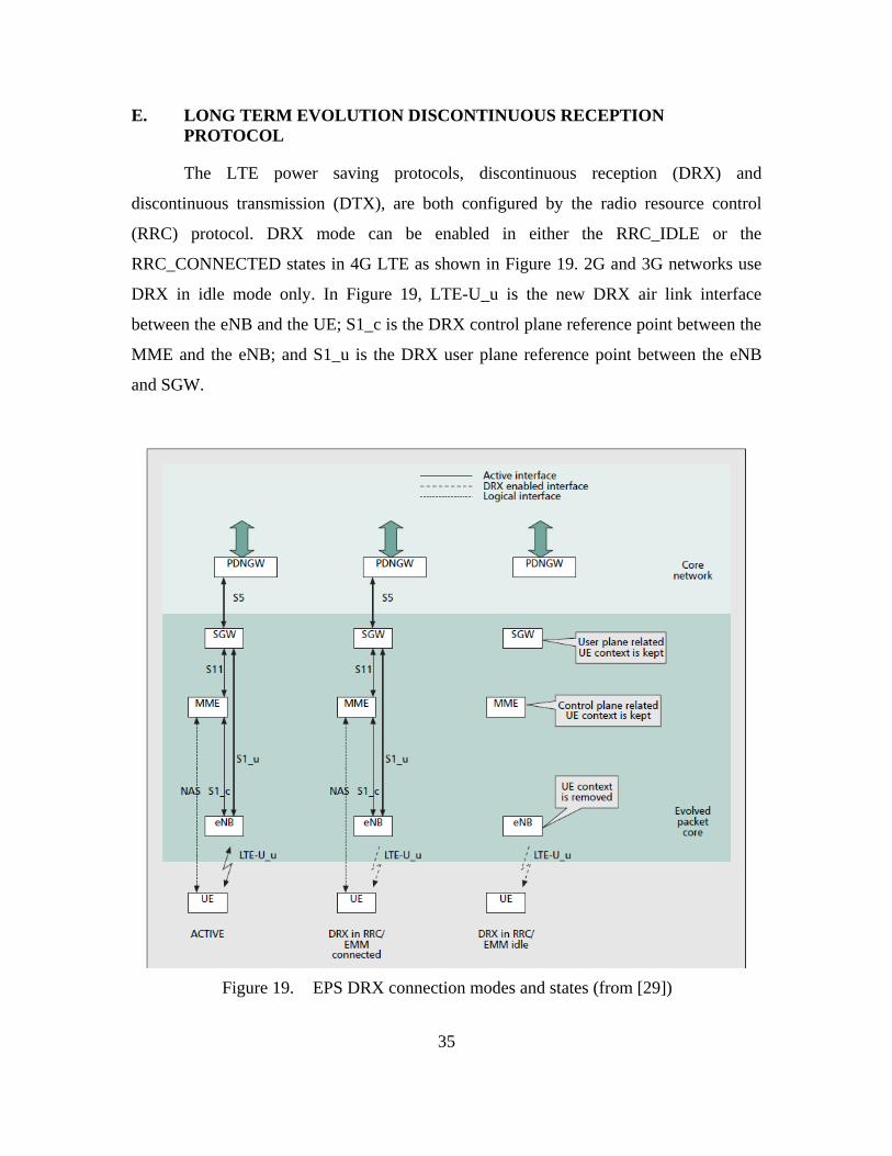
E. LONG TERM EVOLUTION DISCONTINUOUS RECEPTION
PROTOCOL ...................................................................................................35
1. Short and Long Discontinuous Reception Cycles ...........................36
2. Connected State ..................................................................................37
3. Idle State .............................................................................................37
4. User equipment Feature Group Indicators .....................................38
5. Medium Access Control Protocol Layer ..........................................39
F. RELATED WORK IN LONG TERM EVOLUTION SECURITY
VULNERABILITIES DURING DISCONTINUOUS RECEPTION
PERIOD ..........................................................................................................42
III. METHODOLOGY ....................................................................................................45
A. DESCRIPTION OF NS-3 OPEN SOURCE NETWORK
SIMULATOR .................................................................................................45
B. DESCRIPTION OF THE LENA MODULE IN NS-3 ................................45
C. USER EQUIPMENT DISCONTINUOUS RECEPTION PERIOD
ALGORITHM ................................................................................................54
IV. RESULTS ...................................................................................................................55

viii
A. NS-3 LENA MODEL SIMULATOR LIMITATIONS ...............................55
B. LIMITATIONS OF LONG TERM EVOLUTION TRACES ...................56
V. CONCLUSIONS AND FUTURE WORK ...............................................................59
A. CONCLUSIONS ............................................................................................59
B. FUTURE WORK ...........................................................................................60
LIST OF REFERENCES ......................................................................................................63
INITIAL DISTRIBUTION LIST .........................................................................................67

ix
LIST OF FIGURES
Figure 1. Network solutions from GSM to LTE (from [8]) ..............................................5
Figure 2. Circuit and packet domains (from [9]) ...............................................................6
Figure 3. Basic EPS architecture (from [9]) ......................................................................7
Figure 4. 3GPP and non-3GPP access networks (from [9]) ..............................................7
Figure 5. General protocol model for E-UTRAN interfaces (from [11]) ..........................8
Figure 6. E-UTRAN Protocol Stack (from [12]) ..............................................................9
Figure 7. LTE control plane protocol stacks (from [10]) ................................................10
Figure 8. LTE user plane protocol stacks (from [10]) .....................................................10
Figure 9. Time domain view of the LTE downlink data flow (from [4]) ........................11
Figure 10. Downlink channel mapping (from [16]) ..........................................................16
Figure 11. Uplink channel mapping (from [16]) ...............................................................16
Figure 12. Uses of LTE Identifiers (from [18]) .................................................................18
Figure 13. EPS Bearer Service Architecture (from [19]) ..................................................25
Figure 14. PDN connection and EPS bearer (from [24]) ..................................................25
Figure 15. Contention-based RACH Procedure (from [25]) .............................................28
Figure 16. EMM and ECM state transitions (from [26]) ..................................................31
Figure 17. Overview of the security architecture (from [7]) .............................................32
Figure 18. Establishment of NAS and AS security contexts during initial attach (from
[27])..................................................................................................................34
Figure 19. EPS DRX connection modes and states (from [29]) .......................................35
Figure 20. DRX Cycles and Timing (from [22])...............................................................36
Figure 21. Bits 4 and 5 of UE Feature Group Indicators (from [31]) ...............................38
Figure 22. MAC protocol data unit (from [16]) ................................................................39
Figure 23. MAC Random access response (from [16]) .....................................................39
Figure 24. Example of MAC PDU (from [16]) .................................................................41
Figure 25. Values of LCID for DL-SCH (from [16]) ........................................................41
Figure 26. Values of LCID for UL-SCH (from [16]) ........................................................41
Figure 27. Denial of service attack using C-RNTI (from [5]) ...........................................43
Figure 28. Successful Packet Injection Attack (from [5]) .................................................44
Figure 29. Overview of the LTE-EPC simulation model (from [34]) ...............................46
Figure 30. LTE radio protocol stack model for UE on the data plane (from [34]) ...........47
Figure 31. LTE radio protocol stack model for UE on the control plane (from [34]) ......48
Figure 32. LTE PHY and channel model architecture for UE (from [34]) .......................48
Figure 33. LTE radio protocol stack architecture for eNB on the data plane (from
[34])..................................................................................................................49
Figure 34. LTE radio protocol stack architecture for eNB on the control plane (from
[34])..................................................................................................................50
Figure 35. LTE PHY and channel model architecture for eNB (from [34]) .....................50
Figure 36. LTE-EPC data plane protocol stack in LENA model (from [34]) ...................51
Figure 37. EPC control plane model (from [34]) ..............................................................52
Figure 38. LTE sub-frame in LENA (from [34]) ..............................................................53

x
THIS PAGE INTENTIONALLY LEFT BLANK

xi
LIST OF TABLES
Table 1. Logical control and traffic channels provided by the MAC (after [16]) ..........12
Table 2. Physical transport channels used by the MAC (after [16]) ..............................13
Table 3. Physical control and data channels (after [16]) ................................................14
Table 4. Transport processor physical channel control information and channels
(after [16]) ........................................................................................................15
Table 5. Supported PDCCH formats (from [14]) ..........................................................17
Table 6. Description of LTE identifiers (from [18]) ......................................................20
Table 7. RNTI values (from [16]) ..................................................................................21
Table 8. RNTI usage (from [16]) ...................................................................................21
Table 9. Some of the contents of SIB1 (after [23]) ........................................................23
Table 10. Some of the contents of SIB2 (after [23]) ........................................................24
Table 11. Characteristics of RRC protocol states (after [19]) ..........................................27
Table 12. Security Termination Points (from [19]) .........................................................32
Table 13. DRX parameters (after [16]) ............................................................................40
Table 14. User equipment DRX pseudo-code (from [35]) ..............................................54

xii
THIS PAGE INTENTIONALLY LEFT BLANK
xiii
LIST OF ACRONYMS AND ABBREVIATIONS
2G second generation
3G third generation
3GPP Third Generation Partnership Project
4G fourth generation
AAA authentication, authorization and accounting
AKA authentication and key agreement
APN access point name
AS access stratum or access layer
BCH broadcast channel
BCCH broadcast control channel
BS base station
CCCH common control channel
CCE control channel elements
CDMA code division multiple access
CDMA2000 family of 3G mobile technology standards that use CDMA
C-PDU control protocol data unit
CFI control format indicator
CP cyclic prefix
C-RNTI cell radio network temporary identifier
CS circuit switching
DCCH dedicated control channel
DCI downlink control information
DL downlink or transmission path from eNB to the UE
DL-SCH downlink shared channel
DoS denial of service
D-PDU data protocol data unit
DRB data radio bearer
DRX discontinuous reception
DTCH dedicated traffic channel
DTX discontinuous transmission

xiv
DSCP DiffServ code point
ECM EPS connection management
EDGE enhanced data rates for global evolution
EMM EPS mobility management
eNB base station called evolved NodeB or eNodeB in LTE
EPC evolved packet core
ePDG evolved packet data gateway
EPS evolved packet system
E-RAB E-UTRAN radio access bearer
E-UTRA evolved UMTS terrestrial radio access
E-UTRAN evolved UMTS terrestrial radio access network
FAPI femto application platform interface
FDD frequency division duplexing
FFT fast Fourier transform
FGI feature group indicators
GBR guaranteed bit rate
GERAN GSM EDGE radio access network
GPRS general packet radio service
GPS global positioning system
GSM Global System of Mobile Communications
GTP GPRS tunneling protocol
HARQ hybrid automatic repeat-request
HI hybrid ARQ indicator
HSPA high speed packet access
HSS home subscriber server
Hz Hertz, a unit of frequency defined as one cycle per second
IMS IP multimedia subsystem
IMT-Advanced International Mobile Telecommunications Advanced
IP Internet Protocol
IPsec Internet Protocol security
ISI inter symbol interference
ITU International Telecommunications Union
xv
LCID logical channel ID
LTE Long Term Evolution
LTE-A LTE advanced
MAC medium access control protocol
MCH multicast channel
MCCH multicast control channel
MIB master information block
MBMS multimedia broadcast/multicast service
MME mobility management entity
MPLS multiprotocol label switching
MS mobile station
MTCH multicast traffic channel
Node B equivalent to the BTS (base transceiver station) in UMTS
NAS non-access stratum or layer
NPS Naval Postgraduate School
OFDM orthogonal frequency-division multiplexing
OFDMA orthogonal frequency division multiple access
PAPR peak-to-average power ratio
PBCH physical broadcast channel
PCH paging channel
PCCH paging control channel
PCFICH physical control format indicator channel
PCI physical cell identification
PDCCH physical downlink control channel
PDSCH physical downlink shared channel
P-GW packet data network gateway or PDN-GW or PGW
PHICH physical HARQ indicator channel
PDCP packet data convergence protocol
PDN packet data network
PDU protocol data unit
PHY physical layer
PLMN public land mobile network
xvi
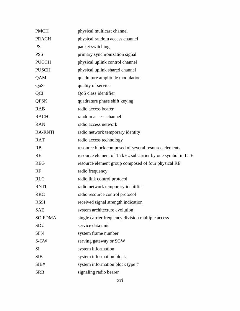
PMCH physical multicast channel
PRACH physical random access channel
PS packet switching
PSS primary synchronization signal
PUCCH physical uplink control channel
PUSCH physical uplink shared channel
QAM quadrature amplitude modulation
QoS quality of service
QCI QoS class identifier
QPSK quadrature phase shift keying
RAB radio access bearer
RACH random access channel
RAN radio access network
RA-RNTI radio network temporary identity
RAT radio access technology
RB resource block composed of several resource elements
RE resource element of 15 kHz subcarrier by one symbol in LTE
REG resource element group composed of four physical RE
RF radio frequency
RLC radio link control protocol
RNTI radio network temporary identifier
RRC radio resource control protocol
RSSI received signal strength indication
SAE system architecture evolution
SC-FDMA single carrier frequency division multiple access
SDU service data unit
SFN system frame number
S-GW serving gateway or SGW
SI system information
SIB system information block
SIB# system information block type #
SRB signaling radio bearer

xvii
SI-RNTI system information RNTI
SS subscriber station
SSS secondary synchronization signal
TCP transmission control protocol
TDD time division duplexing
TDMA time division multiple access
TFT traffic flow templates
TMSI temporary mobile subscriber identity
UCI uplink control information
UDP user datagram protocol
UE user equipment, sometimes called mobile equipment
UL uplink transmission path from the UE to the eNB
UL-SCH uplink shared channel
UMTS Universal Telecommunications System
UTRA Universal Terrestrial Radio Access
UTRAN universal terrestrial radio access network
VoIP voice over Internet Protocol
WCDMA wideband code division multiple access
WiMAX worldwide interoperability for microwave access
WLAN wireless local area network

xviii
THIS PAGE INTENTIONALLY LEFT BLANK

xix
EXECUTIVE SUMMARY
The United States government’s goal of delivering information and services to the
American people, as well as ensuring their defense and safety, depends heavily on mobile
technology. The government is planning on using the high bandwidth and efficiency of
the wireless communications technology called Long Term Evolution (LTE) to achieve
that goal.
Most researchers have focused on improving LTE’s performance and efficiency
for the past ten years and have only recently started investigating the security
vulnerabilities of LTE. The development of the LTE standards have taken into account
the security deficiencies of prior generations of wireless communications technologies,
but some researchers have theorized cyber attacks could still occur in LTE during times
when those security protocols are inactive or weak. The specific vulnerabilities in LTE
often mentioned include illegal use of user and mobile equipment, location tracking,
denial of service attacks, and data integrity attacks. However, none of the researchers has
provided any experimental data to support the claims of such vulnerabilities.
It is hypothesized that if one obtains the user identity information sent in the clear
during network attach, it could then be used to conduct a denial of service or data
integrity attack during the long-term power saving mode. Analysis of LTE standards has
revealed that the user’s equipment can be vulnerable to a cyber attack during the network
attach mode, or during the long term power saving mode, because security protocols are
either inactive or weak.
The open source ns-3 network simulator was investigated as a tool, but it was
found that the LTE model was incomplete and did not include the complete medium
access control protocol header or the data unit and the power saving algorithm. Next,
analysis of captured LTE packet traces available at the Naval Postgraduate School (NPS)
was considered. The Wireshark network protocol analyzer tool indicates a capability to
decode the LTE medium access control, radio link control and packet data convergence
protocol headers, if LTE packet traces are captured using the dissectors for those headers.

xx
However, the NPS LTE packet traces available were not in the libpcap file format
required by Wireshark and the power saving algorithm was not in effect when the traces
were recorded by a different commercial software package. As a result, it was not
possible to analyze if the security protocols were weak during the attach procedure or
during the power saving mode.
The LTE standards have parameters defined for a power saving algorithm but do
not specify how to implement the algorithm. In fact, very few device vendors have
implemented a power saving algorithm, though many currently have plans to do so in the
future. Appropriate laboratory testing equipment and software for analyzing LTE signals
are required to demonstrate a cyber attack in LTE, both of which were not available at the
time of this thesis.

xxi
ACKNOWLEDGMENTS
I would like to thank my advisors, Dr. McEachen and Dr. Garren, for their
guidance throughout the thesis process.

xxii
THIS PAGE INTENTIONALLY LEFT BLANK

1
I. INTRODUCTION
A. IMPORTANCE OF LONG TERM EVOLUTION SECURITY
VULNERABILITY INVESTIGATIONS
The Digital Government Strategy was released on May 23, 2012 [1] with the goal
of delivering “digital government information and services anywhere, anytime, on any
device.” Mobile technology is a big part of that strategy. The “Department of Defense
Mobile Device Strategy,” released in June 2012, focuses on wireless infrastructure,
mobile devices and mobile applications to advance operational effectiveness [2]. The 700
megahertz (MHz) public safety band comprises 24 MHz of spectrum designated for
public safety use. In its Third Report and Order, the Federal Communications
Commission “codified the requirement that 700 MHz public safety broadband network
operators adopt the” Third Generation Partnership Project (3GPP) Release 8 Long Term
Evolution (LTE) “or higher as a common technology platform” [3]. Most cellular service
providers have plans to migrate their current cellular technology to LTE. However, little
research has been done to date into the security vulnerabilities of LTE because most
researchers have been focused on improving its performance and efficiency.
B. SCOPE OF THESIS
LTE is an access communications network of base stations called eNodeBs
(eNBs) that allow connectivity between the mobile devices or user equipment (UE) and
the core network. To save battery power, the UE can turn off its radio transceiver
circuitry, based on various parameters exchanged during the attach procedure with its
serving eNB, using a protocol called Discontinuous Reception (DRX). The radio is
optimized for performance on the downlink from the network to the UE because the
transmitter at the base station is assumed to have plenty of power [4]. Although
processing power has increased, mobile device battery power has stayed essentially
constant, resulting in the optimization of the UE radio for power consumption instead of
efficiency on the uplink to the eNB. During the DRX period, the UE is still connected to
the network and its receiver is turned on periodically to determine if the eNB has sent any
packets to it using paging and if it should become active.

2
The development of the 3GPP LTE standards has taken into account the security
deficiencies of prior generations of wireless communications technologies. It has been
suggested in some LTE security research papers that the long DRX period is one of
several potential security vulnerabilities in LTE [5], [6]. It is hypothesized that if one
obtains the user identity information sent in the clear during network attach, it could then
be used to conduct a denial of service or data integrity attack during the long DRX
period. However, no research has been conducted to confirm such an exploit and to
determine network properties that make the DRX protocol vulnerable to cyber attacks
given LTE’s enhanced security protocols.
This thesis investigates if it is possible to demonstrate a denial of service (DoS)
attack during the LTE power-saving long DRX period using analysis and simulation.
Specifically, it will investigate if an attacker could obtain the Cell Radio Network
Temporary Identifier (C-RNTI) of a UE and use it during the long DRX period to prevent
the UE from communicating with the network. The C-RNTI is a unique and temporary
UE identifier given by the serving eNB to identify one specific radio channel from
another radio channel and one user from another user within the cell. A primary benefit
of the study would be to identify the conditions under which such an attack is possible
and to determine potential mitigation solutions.
C. THESIS METHODOLOGY
In order to determine the specific properties of the long DRX period that makes
LTE vulnerable, it is necessary to examine the radio resource control (RRC) protocols
and algorithms used during establishment and periodic maintenance of the connection
between the UE and the network. It is also important to examine the state of the mutual
authentication between the UE and eNB during the long DRX period.
This study will identify the requirements for investigating DRX vulnerabilities in
LTE and evaluate the use of the open source ns-3 network simulator. The study will not
investigate how to circumvent the five security levels in LTE developed by 3GPP [7].

3
D. THESIS ORGANIZATION
Investigation of the 3GPP LTE standards relevant for attaching to a network,
security establishment and maintenance of the connection are in Section II. Detailed
information on the RRC and DRX protocols is analyzed. The state of the connection and
what triggers the DRX period are examined. The types of LTE radio network temporary
identifiers used during a connection are explored. In addition, prior work in LTE security
vulnerabilities during the DRX period is summarized.
Section III describes the thesis methodology, including the open source ns-3
network simulator and the LTE module within it. Section IV discusses the results of the
thesis. Finally, conclusions and recommendations for further research are discussed in
Section V.

4
THIS PAGE INTENTIONALLY LEFT BLANK

5
II. LITERATURE REVIEW
A. SUMMARY DESCRIPTION OF LONG TERM EVOLUTION NETWORK
ARCHITECTURE
LTE is a fourth generation (4G) wireless communications network whose
standards were first developed by the 3GPP in 2004. LTE is designed to improve upon
the reliability, bandwidth limitations and security vulnerabilities of older cellular
technologies such as Global System for Mobile Communications (GSM), general packet
radio service (GPRS), Universal Mobile Telecommunications System (UMTS), code
division multiple access (CDMA) and high speed packet access (HSPA) [8]. Most
cellular wireless systems consist of a radio access network (RAN) and a core network as
shown in Figure 1. The LTE core network is called the evolved packet core (EPC). The
LTE access stratum (AS) network consists of coordinating base stations, known as eNBs,
which allow connectivity between the mobile devices or UE and the EPC. The access
network of eNBs is also known as the evolved UMTS terrestrial radio access (E-UTRA)
or evolved UMTS terrestrial radio access network (E-UTRAN). The evolved packet
system (EPS) is composed of the E-UTRAN and the EPC.
Figure 1. Network solutions from GSM to LTE (from [8])

6
The 3GPP community made many decisions that have affected the architecture of
the LTE network [9]. Internet Protocol (IP) is used to transport all services in LTE for
routing efficiency, which means each network functional element or network node
requires an IP address. The use of a “flat architecture” means that few network nodes are
involved in the handling of the traffic and protocol conversion is avoided. The user data
(user plane) is separated from the signaling (control plane) to make the scaling of one
independent from the other. The EPC is an evolution of the packet-switched architecture
used in third generation (3G) cellular technologies instead of the circuit-switched
architecture used in second generation (2G) cellular technologies, as shown in Figure 2.
In circuit-switching (CS), dedicated circuits are established between the calling and
called parties from source to destination in the telecommunication network. With packet-
switching (PS), data is transported in packets without the establishment of dedicated
circuits and bandwidth is shared.
Figure 2. Circuit and packet domains (from [9])
The EPC is made up of subcomponents such as the mobility management entity
(MME) for the control plane, the serving gateway (S-GW) and packet data network
gateway (P-GW) for the user plane, and the home subscriber server (HSS) as shown in
Figure 3. The EPC is linked to the external internet, private corporate or the IP
multimedia subsystem (IMS) networks. The MME handles the control plane signaling
related to UE mobility, security for E-UTRAN access, and the tracking and paging of the
UE in idle mode. The MME also maintains context information for UEs in various states
[10]. The HSS is a database that contains user-related and subscriber-related information.
It also provides support functions in mobility management, call and session setup, as well

7
as user authentication, authorization and accounting (AAA) functions. The S-GW and P-
GW transport the user plane IP data traffic between the UE and the external networks.
The S-GW serves the UE by routing the incoming and outgoing IP packets. The P-GW is
selected from access point name (APN) parameters provided by the UE or service
operator. The P-GW routes packets from the EPC to the external IP and IMS networks
using the IP address allocated to the UE during the attach procedure. Transport is through
IP and multiprotocol label switching (MPLS) backbone networks.
Figure 3. Basic EPS architecture (from [9])
3GPP specifications define how 3GPP and non-3GPP radio access networks can
connect with each other as shown in Figure 4 [9]. The network service operator can split
non-3GPP accesses into two categories. Trusted non-3GPP accesses can interact directly
with the EPC. Untrusted non-3GPP accesses use an evolved packet data gateway (ePDG)
to interact with the EPC.
Figure 4. 3GPP and non-3GPP access networks (from [9])

8
1. Radio Protocol Architecture
The LTE radio protocol architecture consists of the logically independent control
and user planes, both of which are separated into a logically independent radio network
layer and a transport network layer [11] as shown in Figure 5. The user plane contains
application data packets processed by protocols such as transmission control protocol
(TCP), user datagram protocol (UDP) and IP [12]. The control plane sends signaling
messages to control network access connections between the UE and the core network, or
the UE and the access network, and user resources. The control plane establishes the user
plane with the desired quality of service (QoS).
Figure 5. General protocol model for E-UTRAN interfaces (from [11])
The layers of the E-UTRAN protocol stack can be seen in Figure 6. A packet
received by a layer is called a service data unit (SDU) and a packet output from a layer is
called a protocol data unit (PDU). In both the user and control planes, the information is
processed by the packet data convergence protocol (PDCP), the radio link control (RLC)
protocol, the medium access control (MAC) protocol and the physical layer (PHY). The
LTE PHY is usually full duplex. The MAC layer determines how to use the transport
channels, how to pack the information in it, and what modulation and coding to configure
the PHY layer with for the correct transmit data rate [4]. When a UE is powered on, it
initiates an attach procedure to register with an eNB in the access network using the RRC

9
protocols, and to register with the MME in the core network using the non-access stratum
(NAS) protocols. The downlink flow progresses upward and uplink flow progresses
downward through the layers shown in Figure 6.
Figure 6. E-UTRAN protocol stack (from [12])
The control plane protocol stack functions are shown in Figure 7. The NAS
protocol is used for non-radio communication between the UE and the core network
MME after attachment. The NAS protocol performs authentication, registration, bearer
context activation and deactivation, as well as location registration management [13]. The
RRC protocol is used to exchange the control plane signaling messages in the AS
between the eNB and the UE [12]. In the uplink, the UE MAC coordinates measurements
from the PHY to the RRC about UE status and local conditions, and the RRC
communicates with the eNB using control messages. In the downlink from the eNB to the
UE, the RRC controls the PHY modulation and configuration settings. The MME can
communicate with the eNB through the S1-AP signaling interface protocol.

10
Figure 7. LTE control plane protocol stacks (from [10])
The user plane protocol stack functions between the eNB and UE are shown in
Figure 8. In the user plane, packets are encapsulated and tunneled between the P-GW
and the eNB using different tunneling protocols depending on the logical interface [12].
The GPRS tunneling protocol (GTP) is used for the S1 interface between the eNB and S-
GW, and the S5/S8 interface between the S-GW and P-GW. S5 is used if the two devices
are in the same network, and S8 is used if they are in different networks. GTP is used to
encapsulate user data transported through the core network and also carries UE specific
signaling traffic between various core networks.
Figure 8. LTE user plane protocol stacks (from [10])
A logical diagram of E-UTRAN protocol layers with data flow in the downlink
from network to UE is shown in Figure 9. The duration of each time slot is 0.5
milliseconds (ms), each sub-frame is two slots, and each radio frame contains 10 sub-

11
frames. Each sub-frame is also known as the transmission time interval. An uplink or
downlink physical channel corresponds to a set of resource elements (RE) carrying
information originating from the higher layers [14]. Each RE is uniquely defined by an
index pair in a time slot of a sub-frame.
Figure 9. Time domain view of the LTE downlink data flow (from [4])
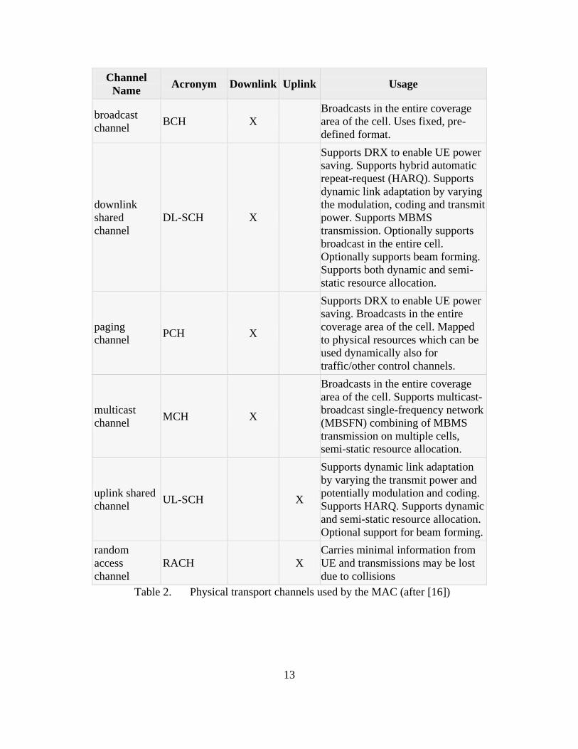
2. Physical, Logical and Transport Channels
UE and functional entities must be explicitly allocated uplink and downlink non-
overlapping resources to send and receive LTE duplex traffic. Data and signaling
messages are carried on different types of logical or transport or physical channels
depending on the kind of information they carry between the layers and by the way in
which the information is processed. A common shared channel is used for all users in a
cell (point to multipoint), whereas dedicated channels are used to communicate with only
one user (point to point). The RLC layer passes data to the MAC layer as logical channels
defined in Table 1 [15]. The MAC layer formats and sends the logical channel data to the
physical layer as transport channels defined in Table 2. The physical layer encodes the

12
transport channel data to the physical channels defined in Table 3. Table 4 shows the
control information created by the transport channel processor to support the low-level
operation of the PHY and the physical control channels used to send this information.
Channel
Name Acronym
Control
channel
Traffic
channel Downlink Uplink Usage
broadcast
control
channel
BCCH X
X
For broadcasting system
control information
paging
control
channel
PCCH X
X
For paging when the
network does not know the
location cell of the UE or to
provide system information
change notifications
common
control
channel
CCCH X
X X
For transmitting control
information between a
network and UEs having no
RRC connection
dedicated
control
channel
DCCH X
X X
For transmitting dedicated
control information bi-
directionally between a
network and a UE having
an RRC connection
dedicated
traffic
channel
DTCH
X X X
For the transfer of user
information, dedicated to
one UE
multicast
control
channel
MCCH X
X
For transmitting point-to-
multipoint control
information from the
network to the UEs that
receive multimedia
broadcast multicast service
(MBMS)
multicast
traffic
channel
MTCH
X X
For transmitting point-to-
multipoint traffic data from
the network to the UEs that
receive MBMS
Table 1. Logical control and traffic channels provided by the MAC (after [16])
13
Channel
Name Acronym Downlink Uplink Usage
broadcast
channel BCH X
Broadcasts in the entire coverage
area of the cell. Uses fixed, pre-
defined format.
downlink
shared
channel
DL-SCH X
Supports DRX to enable UE power
saving. Supports hybrid automatic
repeat-request (HARQ). Supports
dynamic link adaptation by varying
the modulation, coding and transmit
power. Supports MBMS
transmission. Optionally supports
broadcast in the entire cell.
Optionally supports beam forming.
Supports both dynamic and semi-
static resource allocation.
paging
channel PCH X
Supports DRX to enable UE power
saving. Broadcasts in the entire
coverage area of the cell. Mapped
to physical resources which can be
used dynamically also for
traffic/other control channels.
multicast
channel MCH X
Broadcasts in the entire coverage
area of the cell. Supports multicast-
broadcast single-frequency network
(MBSFN) combining of MBMS
transmission on multiple cells,
semi-static resource allocation.
uplink shared
channel UL-SCH
X
Supports dynamic link adaptation
by varying the transmit power and
potentially modulation and coding.
Supports HARQ. Supports dynamic
and semi-static resource allocation.
Optional support for beam forming.
random
access
channel
RACH
X
Carries minimal information from
UE and transmissions may be lost
due to collisions
Table 2. Physical transport channels used by the MAC (after [16])

14
Channel
Name Acronym Downlink Uplink Usage
physical
broadcast
channel
PBCH X
Within a 40 ms interval, broadcasts a limited
number of parameters essential for initial
access of the cell (downlink system
bandwidth, the physical HARQ indicator
channel structure, and the most significant
eight-bits of the system frame number) in a
master information block (MIB) which is 14
bits long.
physical
downlink
shared
channel
PDSCH X
Carries the DL-SCH and PCH.
Quadrature phase shift keying (QPSK), 16-
QAM (quadrature amplitude modulation),
and 64-QAM modulation
physical
downlink
control
channel
PDCCH X
Informs the UE about the resource allocation
of PCH and DL-SCH, and HARQ
information related to DL-SCH. Carries the
uplink scheduling grant. QPSK modulation.
physical
multicast
channel
PMCH X
Carries the MCH
QPSK, 16-QAM, and 64-QAM modulation
physical
uplink
shared
channel
PUSCH
X Carries the UL-SCH
QPSK, 16-QAM, and 64-QAM modulation
physical
uplink
control
channel
PUCCH
X
Carries HARQ, positive acknowledgments
(ACKs) or negative acknowledgments
(NACKs) in response to downlink
transmission, scheduling request (SR),
channel quality indicators (CQI) reports.
Binary phase shift keying (BPSK) and QPSK
modulation.
physical
random
access
channel
PRACH
X
Carries the random access preamble a UE
uses to access the network in non-
synchronized mode and allow the UE to
synchronize timing with the eNB
Table 3. Physical control and data channels (after [16])

15
Field Name Acronym Downlink Uplink Usage
downlink control
information DCI X
Contains transmission resource
assignments and other control
information (i.e., power, HARQ) for
a UE or group of UEs
control format
indicator CFI X
32-bit long CFI is mapped to 16 RE
in the first orthogonal frequency-
division multiplexing (OFDM)
symbol of each downlink frame
hybrid ARQ
indicator HI X
The eNB sends to the UE an ACK
(111) or NACK (000) for data sent
using the UL-SCH.
uplink control
information UCI
X
Contains SR, HARQ ACK/NACK,
CQI
physical control
format indicator
channel
PCFICH X
Carries the CFI used to dynamically
indicate the number of symbols to be
used for PDCCH
physical HARQ
indicator channel PHICH X
Carries HARQ ACK/NAKs in
response to uplink transmissions
which indicates to the UE whether
the eNB correctly received uplink
user data carried on the PUSCH.
QPSK modulation.
Table 4. Transport processor physical channel control information and channels
(after [16])
The mapping between the logical, physical and transport channels for the
downlink can be seen in Figure 10. In the uplink, the common control channel (CCCH),
dedicated control channel (DCCH) and dedicated traffic channel (DTCH) are all mapped
to the uplink shared channel (UL-SCH) as shown in Figure 11 [4].

16
Figure 10. Downlink channel mapping (from [16])
Figure 11. Uplink channel mapping (from [16])
3. Physical Downlink Control Channel
All MAC transmissions on the UL-SCH must be scheduled by the random access
channel (RACH) procedure. The physical downlink shared channel (PDSCH) carries all
user data and all multi-cast signaling messages. The physical downlink control channel
(PDCCH) carries the layer one downlink control information (DCI) message that
indicates who the data is for, as well as the type and format of data transmitted [17].

17
There can be four PDCCH formats each of which has a set number of control channel
elements (CCE) as shown in Table 5 [14]. Each CCE is composed of nine resource
element groups (REG), and each REG is composed of four physical resource elements
(RE). Multiple PDCCHs can be transmitted in a sub-frame by the eNB. The physical
control format indicator channel (PCFICH) carries information about the number of
orthogonal frequency-division multiplexing (OFDM) symbols used for transmission of
PDCCHs in a sub-frame.
PDCCH format Number of
CCE
Number of
REG
Number of PDCCH
bits
0 1 9 72
1 2 18 144
2 4 36 288
3 8 72 576
Table 5. Supported PDCCH formats (from [14])
The eNB can use one of many defined DCI formats based on the transmission
mode and the type of radio network temporary identifiers (RNTI) for the associated
PDCCH. Since the location of a specific PDCCH and type of DCI can vary based on
whether it is for a specific UE or a shared broadcast, the UE needs to search all the
possible locations in the frame for it and conduct a blind decoding of the PDCCH.
B. LONG TERM EVOLUTION RADIO NETWORK TEMPORARY
IDENTIFIERS
There are many types of radio network temporary identifiers (RNTI) used in the
LTE network as shown in Figure 12 and details of each one are given in Table 6.

18
Figure 12. Uses of LTE identifiers (from [18])

19

20
Table 6. Description of LTE identifiers (from [18])
1. Cell Radio Network Temporary Identifier
The cell radio network temporary identifier (C-RNTI) is assigned by the serving
eNB to a UE during the RRC attach procedure. The C-RNTI is an E-UTRAN specific
identifier and the EPC network has no context information about it. The C-RNTI is
transmitted in clear text [6] since there are no security protocols during the initial attach
procedure.
There are various versions of the C-RNTI [19] used by the E-UTRAN in a cell:
C-RNTI: unique identification used for identifying RRC Connection and
scheduling
Semi-persistent scheduling C-RNTI: unique identification used for semi-
persistent scheduling;
Temporary C-RNTI: identification used for the random access procedure
TPC-PUSCH-RNTI: identification used for the power control of PUSCH
TPC-PUCCH-RNTI: identification used for the power control of PUCCH
The UE may be configured by RRC with a DRX functionality that controls the
UE’s PDCCH monitoring activity for the UE’s C-RNTI or TPC-PUCCH-RNTI or TPC-
PUSCH-RNTI or semi-persistent scheduling C-RNTI [16].

21
A UE uses the same C-RNTI on all serving cells [16] in the E-UTRAN. RNTI
values used in the MAC layer are shown in Table 7.
Table 7. RNTI values (from [16])
The usage of the RNTI values by the MAC layer in the associated transport and
logical channels are shown in Table 8.
Table 8. RNTI usage (from [16])

22
C. CONNECTING TO A LONG TERM EVOLUTION NETWORK
When a UE initially powers on, it uses an initial synchronization process to search
for the correct frequency from the many different ones available on the air. Timing is
critical because a UE can be moving from the base station, and LTE requires
microsecond level precision. The speed-of-light propagation delay can cause a collision
or a timing problem [4]. Once synchronized to the correct frequency, the UE reads the
system information to find the allowable public land mobile network (PLMN) to connect
to [20]. If the PLMN value is correct, it reads more system information on network
resources. When a subscribed user is in her operator’s PLMN, it is called a home-PLMN.
Roaming allows users to move outside their home network and use the resources from
another operator’s network, called a visited-PLMN.
In order to gain access to the network’s resources or channels, the UE initiates a
random access procedure over a shared channel with the eNB using the RRC protocol. If
there are many UEs in the cell, a contention based random access procedure is used to
prevent collisions between the many requests. Alternatively, a contention free or non-
contention based random access procedure can be used whereby an eNB assigns a 6 bit
preamble code to the UE to prevent its request from colliding with other UE requests.
1. System Information Acquisition
When a UE first powers on, it attempts to acquire physical cell identification
(PCI), time slot and frame synchronization so it can read system information (SI) from a
particular network using a system information acquisition procedure. The UE detects the
PCI from the primary synchronization signal (PSS) and secondary synchronization signal
(SSS) regularly broadcast by the eNB. System information is divided into a master
information block (MIB) and a number of system information blocks (SIBs). The
contents of the MIB and SIBs are specified in [21].
The MIB defines the most essential physical layer information of the cell required
to receive further system information [19]. SystemInformationBlockType1 (SIB1)
contains information relevant when evaluating if a UE is allowed to access a cell and

23
defines the scheduling of other system information blocks.
SystemInformationBlockType2 (SIB2) contains radio resource configuration, common
and shared channel information which is common for all UEs. A 28-bit E-UTRAN cell
identifier which identifies a radio cell within a PLMN is broadcast with SIB1 [22]. The
MIB is mapped on the logical BCCH and carried on transport and physical BCH while all
other SI messages are mapped on the BCCH and dynamically carried on DL-SCH where
they can be identified through the System Information RNTI (SI-RNTI). Both the MIB
and SIB1 use a fixed schedule with a periodicity of 40 and 80 milliseconds, respectively,
while the scheduling of other SI messages is flexible and indicated by SIB1. The content
of the MIB includes the downlink channel bandwidth in terms of resource blocks (RB),
the PHICH configuration (duration and resource) and the system frame number (SFN)
[19]. Some of the cell access parameters contained in SIB1 and SIB2 are shown in Table
9 and Table 10.
PLMN identity: Up to 6 PLMN identities can be specified
Tracking area code: Range from 0 to 65546
Cell Id: 28 bits eNB identity
Cell barred: whether cell is barred or not
Intra Frequency cell reselection info: To select other cells when the target cell is
barred
CSG indication: To indicate whether this cell is a Closed Subscriber Group (CSG)
cell or not. If it is CSG cell, then CSG identity stored in the UE should match with
CSG id of the cell
q-RxLevMin: Minimum required level in the cell
Band indicator: Cell frequency band indicator
Scheduling information of other SIBs
Table 9. Some of the contents of SIB1 (after [23])
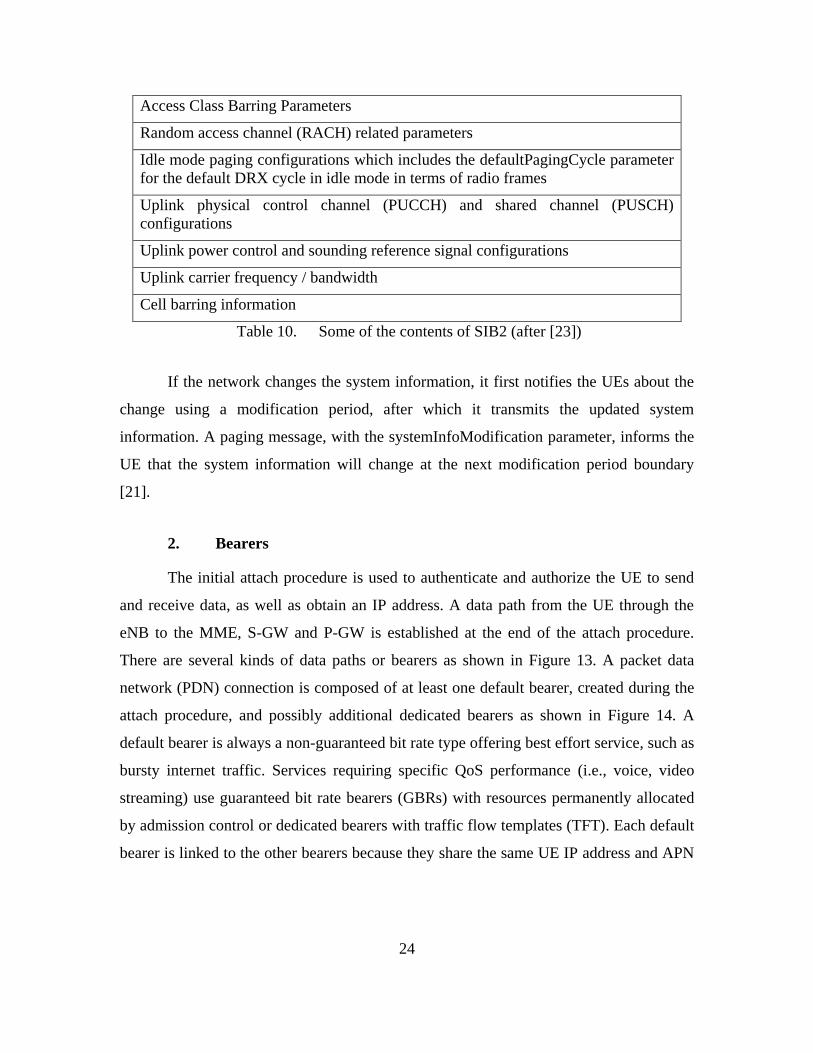
24
Access Class Barring Parameters
Random access channel (RACH) related parameters
Idle mode paging configurations which includes the defaultPagingCycle parameter
for the default DRX cycle in idle mode in terms of radio frames
Uplink physical control channel (PUCCH) and shared channel (PUSCH)
configurations
Uplink power control and sounding reference signal configurations
Uplink carrier frequency / bandwidth
Cell barring information
Table 10. Some of the contents of SIB2 (after [23])
If the network changes the system information, it first notifies the UEs about the
change using a modification period, after which it transmits the updated system
information. A paging message, with the systemInfoModification parameter, informs the
UE that the system information will change at the next modification period boundary
[21].
2. Bearers
The initial attach procedure is used to authenticate and authorize the UE to send
and receive data, as well as obtain an IP address. A data path from the UE through the
eNB to the MME, S-GW and P-GW is established at the end of the attach procedure.
There are several kinds of data paths or bearers as shown in Figure 13. A packet data
network (PDN) connection is composed of at least one default bearer, created during the
attach procedure, and possibly additional dedicated bearers as shown in Figure 14. A
default bearer is always a non-guaranteed bit rate type offering best effort service, such as
bursty internet traffic. Services requiring specific QoS performance (i.e., voice, video
streaming) use guaranteed bit rate bearers (GBRs) with resources permanently allocated
by admission control or dedicated bearers with traffic flow templates (TFT). Each default
bearer is linked to the other bearers because they share the same UE IP address and APN

25
identifier. A data radio bearer (DRB) transports the packets between a UE and an eNB.
An E-UTRAN radio access bearer (E-RAB) transports the packets between the UE and
the EPC.
P-GWS-GW Peer
Entity
UE eNB
EPS Bearer
Radio Bearer S1 Bearer
End-to-end Service
External Bearer
Radio S5/S8
Internet
S1
E-UTRAN EPC
Gi
E-RAB S5/S8 Bearer
Figure 13. EPS bearer service architecture (from [19])
Figure 14. PDN connection and EPS bearer (from [24])
3. Radio Resource Control Protocol
The radio resource control (RRC) protocol, which exists in the UE and the eNB,
is used to perform connection control and management, including establishment of the
radio bearer. RRC provides broadcast of common control information from the upper
layers and transfer of dedicated control information for a specific UE. The main services
and functions of the RRC layer [19] include:

26
Broadcast of system information related to the non-access stratum (NAS)
Broadcast of system information related to the access stratum (AS)
Paging
Establishment, maintenance and release of an RRC connection between
the UE and E-UTRAN including:
Allocation of temporary identifiers between UE and E-UTRAN
Configuration of low priority signaling radio bearers (SRB) and
high priority SRB
Configuration of the security parameters and security functions including
key management
Establishment, configuration, maintenance and release of point to point
radio bearers
Mobility functions including:
UE measurement reporting and control of the reporting for inter-
cell and inter-RAT (radio access technologies) mobility
Handover
UE cell selection and reselection and control of cell selection and
reselection
Context transfer at handover
Notification and counting for MBMS services
Establishment, configuration, maintenance and release of radio bearers for
MBMS services
QoS management functions
UE measurement reporting and control of the reporting
NAS direct message transfer to/from NAS from/to UE
The RRC functions depend upon whether the UE is in the idle or connected mode.
A UE is in the RRC_CONNECTED state when an RRC connection has been established;
otherwise it is in the RRC_IDLE state [21]. In RRC_IDLE, the UE camps on a cell after
a cell selection or reselection process monitoring information on radio link quality and
cell status [12]. In RRC_CONNECTED, the UE monitors control channels associated
with the shared data channel. The characteristics of RRC states are shown in Table 11.

27
Mode States And Transitions
RRC_IDLE
Operator’s PLMN selection
A UE specific DRX may be configured by NAS upper layer
UE monitors a paging channel to detect incoming calls,
system information
Cell selection or re-selection mobility
The UE shall have been allocated an ID which uniquely
identifies the UE in a tracking area
No RRC context stored in the eNB
RRC_CONNECTED
UE has an E-UTRAN-RRC connection and context in E-
UTRAN
E-UTRAN knows the cell which the UE belongs to
Network controlled mobility (handover and inter-RAT cell
change)
UE performs neighbor cell measurements and reports it
At PDCP/RLC/MAC level:
o UE can transmit and/or receive data to/from network
o UE monitors control signaling channel for shared
data channel to determine if data is for it
o UE reports channel quality information and feedback
information
o DRX period can be configured by the eNB according
to UE activity level for UE power saving and
efficient resource utilization
Table 11. Characteristics of RRC protocol states (after [19])
4. Random Access Channel Procedure
When the UE wants to initially attach to a LTE network, it must request a RRC
connection from the eNB using a random access channel (RACH) procedure in order to
obtain dedicated resources for a radio bearer. All MAC transmissions on the uplink
shared channel (UL-SCH) must be scheduled RACH procedures. The RACH is triggered
by five events [19]:
28
1. Initial access from disconnected state (RRC_IDLE)
2. RRC connection re-establishment or radio failure
3. Handover requiring random access procedure
4. Downlink or uplink data arrival during RRC_CONNECTED after uplink
PHY has lost synchronization (possibly due to power save operation) or
for UE positioning
5. Uplink data arrival when no dedicated scheduling request (PUCCH)
channels available
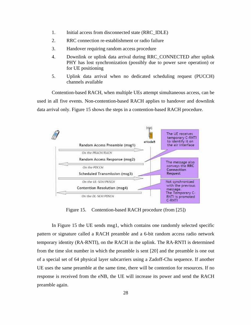
Contention-based RACH, when multiple UEs attempt simultaneous access, can be
used in all five events. Non-contention-based RACH applies to handover and downlink
data arrival only. Figure 15 shows the steps in a contention-based RACH procedure.
Figure 15. Contention-based RACH procedure (from [25])
In Figure 15 the UE sends msg1, which contains one randomly selected specific
pattern or signature called a RACH preamble and a 6-bit random access radio network
temporary identity (RA-RNTI), on the RACH in the uplink. The RA-RNTI is determined
from the time slot number in which the preamble is sent [20] and the preamble is one out
of a special set of 64 physical layer subcarriers using a Zadoff-Chu sequence. If another
UE uses the same preamble at the same time, there will be contention for resources. If no
response is received from the eNB, the UE will increase its power and send the RACH
preamble again.

29
The eNB’s random access response in msg2 is addressed to the RA-RNTI and
sent by the MAC layer on the physical downlink control channel (PDCCH) using the
downlink shared channel (DL-SCH). It indicates that resources have been reserved for
the UE. For initial access, the response includes a RA-preamble identifier, timing
alignment information, initial uplink grant, and assignment of a 16-bit temporary cell
radio network temporary identifier (C-RNTI) to the UE.
The UE sends a scheduled transmission response in msg3 with the temporary C-
RNTI requesting RRC connection, using hybrid automatic repeat-request (HARQ) and
radio link control (RLC) transparent mode on the UL-SCH. In case the assigned
temporary C-RNTI is in use by another UE, the message also contains either the
temporary mobile subscriber identity (TMSI), if the UE has previously connected to the
same network, or a random value, if the UE is connecting for the very first time. The
TMSI is randomly assigned by the network to every registered UE.
The eNB sends msg4 with a new C-RNTI which will be used for further
communication so that only the UE with it continues with the transmission while others
back-off and try again after expiration of RACH specific timers. The C-RNTI is used in
calculating the cyclic redundancy check (CRC) of PDCCH transmissions in the DL-SCH
and for scrambling in the UL-SCH [14]. If no CRC error is detected, the PDDCH is for
the UE. At the end of a successful RACH procedure, the UE is in RRC_CONNECTED
state enabling it to exchange data with the eNB using dedicated signaling radio bearer 1
(SRB1). The UE can now read the PDCCH and PDSCH. During each DL-SCH, the UE
checks the CRC with its C-RNTI. If the CRC is decoded successfully with its C-RNTI,
the message is for the UE and it can find the DCI format from the payload size in that
PDCCH.
5. Evolved Packet System Connection Management
There are two sets of states defined for the UE based on the information held by
the MME as described in [10] and summarized here. The EPS mobility management
(EMM) states of EMM-DEREGISTERED and EMM-REGISTERED are used to keep
track of the current location of a UE. The EPS connection management (ECM) states of

30
ECM-IDLE and ECM-CONNECTED describe the signaling connectivity between the
UE and the EPC. In general, the ECM and EMM states are independent of each other.
The UE enters the ECM-IDLE state when its signaling connection to the MME
has been released or broken. In the ECM-IDLE state, there is no NAS signaling
connection between the UE and the MME, and there is no context for the UE held in the
eNB. As a result, the UE and the network can become unsynchronized with different EPS
bearers. The ECM-CONNECTED state occurs when a UE is in RRC_CONNECTED
state with the eNB, has a S1 connection with the MME and the EPS bearers are
synchronized. In the ECM-CONNECTED state, the UE location is known to the MME
with an accuracy of a serving eNB identity.
The UE and MME enter the EMM-REGISTERED state by a successful
registration using the attach procedure with the eNB. After performing the detach
procedure, the state is changed to EMM-DEREGISTERED in the UE and in the MME. In
the EMM DEREGISTERED state, the EMM context in MME holds no valid location or
routing information for the UE. The UE is not reachable by a MME, as the UE location is
not known. In the EMM-DEREGISTERED state, some UE context can still be stored in
the UE and MME to avoid running an authentication and key agreement (AKA)
procedure during every attach procedure between the UE and MME.
The ECM and EMM states and transitions can be seen in Figure 16. In the EMM-
REGISTERED and ECM-IDLE state, the UE performs a periodic tracking area updating
procedure to maintain registration and enable the MME to page the UE, such as during
the discontinuous reception (DRX) period.

31
Figure 16. EMM and ECM state transitions (from [26])
D. LONG TERM EVOLUTION SECURITY
1. Security Architecture
A diagram of the 3GPP security architecture for LTE is shown in Figure 17. Both
[6] and [27] present a comprehensive survey of security architecture, vulnerabilities and
solutions in LTE and LTE-A networks. The network access security features (I) provide
users with secure access to services, and protect against attacks on the radio access link
[7]. The network domain security features (II), such as Internet Protocol security (IPsec),
enable nodes to securely exchange signaling data, user data (between AN and SN, and
within AN), and protect against attacks on the wireline network. The user domain
security features (III) secure access to mobile stations. The application domain security
features (IV) enable applications in the user and in the provider domain to securely
exchange messages. The visibility and configurability of security features (V) enables the
user to inform him whether a security feature is in operation or not and whether the use
and provision of services should depend on the security feature. The defined security
termination points in an EPS network are shown in Table 12. RRC integrity and
confidentiality protection are provided by the PDCP layer between UE and eNB after the
attach procedure and no layers below PDCP are protected [27]. Due to higher error rates

32
and longer round trip times in wireless networks, robust header compression (ROHC) is
used to reduce the amount of header information that would travel over the air. As a
result, security occurs below the ROHC since ROHC can only operate on unencrypted
packets [4]. Ciphering is used for both AS and NAS signaling messages, as well as for
AS user plane data.
Figure 17. Overview of the security architecture (from [7])
Ciphering Integrity Protection
NAS Signalling Required and terminated in
MME
Required and terminated in
MME
U-Plane Data Required and terminated in
eNB
Not Required
(NOTE 1)
RRC Signalling
(AS)
Required and terminated in
eNB
Required and terminated in
eNB
MAC Signalling
(AS)
Not required Not required
NOTE 1: Integrity protection for U-Plane is not required and thus it is not
supported between UE and Serving Gateway or for the transport of user
plane data between eNB and Serving Gateway on S1 interface.
Table 12. Security termination points (from [19])

33
The LTE system utilizes an authentication and key agreement (AKA) procedure
to achieve mutual authentication between the UE and the MME, as well as generate the
ciphering key and integrity key used to derive different session keys for the encryption
and the integrity protection [28]. Different AKA procedures are used when the UE
accesses the EPC through distinct non-3GPP access networks.
2. Access Stratum Security
The lifetime of an access stratum (AS) security context is tied to the RRC
connection because eNB keys are generated when the UE moves to connected mode and
deleted when the UE goes to idle mode [19], [27]. Temporary identities are used to avoid
the compromise of permanent identities between entities and reduce the time period
during which an attacker could use them. AS security involves integrity protection and
ciphering of RRC signaling carried by SRBs, and ciphering of user data carried by DRBs
[21]. The RACH procedure results in a RRC_CONNECTED state and establishment of
the dedicated SRB1. SRB1 is then used to transfer the initial NAS message from the UE
to the MME, which results in the eNB receiving the UE context information from the
EPC and establishing the S1 connection.
Upon receiving the UE context from the EPC, the eNB activates security using
the AS security mode command procedure. The RRC command and successful response
messages to activate security are integrity protected, while ciphering starts only after
completion of the security mode command procedure. The use of cryptographic
protection on S1-MME and X2-C is an operator’s decision [7]. Once security is activated,
all RRC messages receive integrity protection and ciphering by the PDCP layer. The eNB
does not establish SRB2 and user DRBs prior to activating security and the UE only
accepts a handover message when security has been activated. The integrity protection
algorithm is common for SRB1 and SRB2. The ciphering algorithm is common for all
radio bearers (i.e., SRB1, SRB2 and DRBs). SRB0 is not integrity protected or ciphered
[7]. S1 interface signaling protection is optional [27]. The three defined SRBs (SRB0,
SRB1 and SRB2) are used only for the transmission of RRC and NAS messages.

34
AS level security mode command procedure configures AS security (RRC and
user plane) and NAS level security mode command procedure configures NAS security.
The eNB keys are cryptographically separated from the EPC keys used for NAS
protection to make it impossible to use the eNB key to figure out an EPC key [19]. Once
NAS integrity has been activated, NAS messages without integrity protection are not
accepted by the UE or MME [7]. The NAS service request is always integrity protected
and the NAS attach request message is integrity protected if the EPS security context is
not deleted while the UE is in EMM-DEREGISTERED state. The NAS security context
has a longer lifetime than the AS security context and can also stay alive when the UE
goes to idle until the EPS security context is deleted in either the UE or MME [27].
The AS and NAS security contexts are established during initial attach as shown
in Figure 18.
Figure 18. Establishment of NAS and AS security contexts during initial attach (from
[27])
35
E. LONG TERM EVOLUTION DISCONTINUOUS RECEPTION
PROTOCOL
The LTE power saving protocols, discontinuous reception (DRX) and
discontinuous transmission (DTX), are both configured by the radio resource control
(RRC) protocol. DRX mode can be enabled in either the RRC_IDLE or the
RRC_CONNECTED states in 4G LTE as shown in Figure 19. 2G and 3G networks use
DRX in idle mode only. In Figure 19, LTE-U_u is the new DRX air link interface
between the eNB and the UE; S1_c is the DRX control plane reference point between the
MME and the eNB; and S1_u is the DRX user plane reference point between the eNB
and SGW.
Figure 19. EPS DRX connection modes and states (from [29])

36
The eNB advertises the default DRX paging cycle in
SystemInformationBlockType2 (SIB2) during the network attach procedure. The UE can
use the DRX page cycle broadcast in SIB2 or propose a DRX cycle length using the
InDeviceCoexIndication message [21]. In DRX mode, the UE powers down most of its
circuitry when there are no packets to be transmitted or received [29]. The UE’s
transceiver is turned on periodically to transmit or receive packets. During DRX, the UE
can still make periodic neighboring cell signal quality measurements and tracking area
updates that it sends in periodic uplink packets to the eNB. Whether the UE keeps in sync
with uplink transmission or not depends on whether the UE is registered with an eNB
(RRC_CONNECTED state) or not (RRC_IDLE state). The transition between the short
DRX cycle, the long DRX cycle and continuous reception is controlled either by a timer
or by explicit commands from the eNB [30].
1. Short and Long Discontinuous Reception Cycles
The DRX cycle generally consists of a periodic repetition of an active time or “on
duration” when the UE monitors the PDCCH, and an inactive time or “sleep mode” when
it does not monitor downlink channels, as shown in Figure 20.
Figure 20. DRX cycles and timing (from [22])

37
A short DRX cycle has a shorter inactive time and is generally used for bursts of
traffic where packets arrive more often with inactivity in between, such as in web
browsing. The UE monitors the physical downlink control channel (PDCCH) more
frequently during the short DRX cycle. The long DRX cycle has a longer inactive time
and is most often used when packets arrive at a lower rate or during periods of low
activity, such as during the RRC_IDLE state. The UE is usually configured to use a short
DRX cycle for a predefined time before enabling a constant long DRX cycle to reduce
the UE wake up time in case unexpected data arrives immediately after the DRX cycle is
enabled [29]. Durations for long and short DRX are configured by the RRC and the
transition is determined by eNB MAC control commands or by the UE based on an
activity timer [4].
2. Connected State
The DRX mode can be enabled in RRC_CONNECTED state by either the eNB or
UE when there are no outstanding or new packets to be transmitted or received [29]. In
this state, the S1, NAS, and RRC connections are active and the rest of the network is
unaware of the DRX data exchange on the air interface.
When the UE periodically wakes up, it checks to determine if pages have been
transmitted by the eNB on the PDCCH with a radio network temporary identifier (C-
RNTI or TPC-PUCCH-RNTI or TPC-PUSCH-RNTI or semi-persistent scheduling C-
RNTI) assigned by the network during the attach procedure. The UE will return to active
mode whenever a packet arrives from the eNB for it or whenever the UE needs to
transmit packets to the eNB.
3. Idle State
When the UE does not have packets to be received and/or transmitted for an
extended period of time, the UE will transition from the short to the long DRX period.
The eNB will initiate the release of UE’s RRC connection and request the MME to
release the UE’s S1 connection [29]. Subsequently, the eNB will remove the UE’s
context from the database, but the MME and SGW will only remove the eNB specific

38
part of the UE context. In this RRC_IDLE state, the UE is registered with EPS mobility
management (EMM) but does not have an active session, meaning the S1, NAS, and
RRC connections are non-existent [29]. The UE controls mobility by using signal quality
measurements and tracking area updates of neighboring cells.
During this long DRX period, the UE wakes up periodically to listen to downlink
transmissions and can initiate uplink traffic by requesting a RRC connection with the
serving eNB. If the S-GW detects data addressed to the UE, the MME will ask all eNBs
in the tracking area where the UE was last seen to transmit a page to the UE. If a UE
finds its temporary mobile subscriber identity (STMSI) in the page message, it will
initiate the random access procedure by sending the random access channel (RACH)
preamble to the eNB. In RRC_CONNECTED state, the UE will send a transparent
payload containing the NAS service request to the eNB, which will be forwarded to the
MME, and the UE will return to EMM_ACTIVE mode. The eNB will then enable over-
the-air encryption by sending the security mode command to the MME and establish the
default data bearer.
4. User Equipment Feature Group Indicators
During the attach procedure, the UE signals its support for DRX which is
forwarded to the MME [10]. Each bit of the feature group indicators (FGI) indicates the
UE’s support of a specific feature and is submitted to the network during the initial
registration and attach procedure as part of the UE capability transfer [22]. Bits 4 and 5
define the support of the DRX cycle as shown in Figure 21.
Figure 21. Bits 4 and 5 of UE feature group indicators (from [31])

39
5. Medium Access Control Protocol Layer
The transition between the long and short DRX cycles is determined by the
medium access control (MAC) layer control commands in the eNB or by the UE based
on information exchanged during the attach procedure. The MAC handles the broadcast
channel (BCH), downlink shared channel (DL-SCH), paging channel (PCH), uplink
shared channel (UL-SCH) and the random access channel (RACH) [16].
A MAC protocol data unit (PDU) consists of a variable size MAC header, zero or
more MAC random access responses (RAR) or payloads and optional padding as shown
in Figure 22.
Figure 22. MAC protocol data unit (from [16])
The MAC RAR contains the 16-bit temporary C-RNTI used by the UE during
RACH procedure as shown in Figure 23.
Figure 23. MAC Random access response (from [16])
The RRC MAC-MainConfig message, which is used to specify the MAC main
configuration for signaling and data radio bearers, contains a DRX-Config section [27].
Table 13 describes some of the parameters and timers specified in DRX-Config.
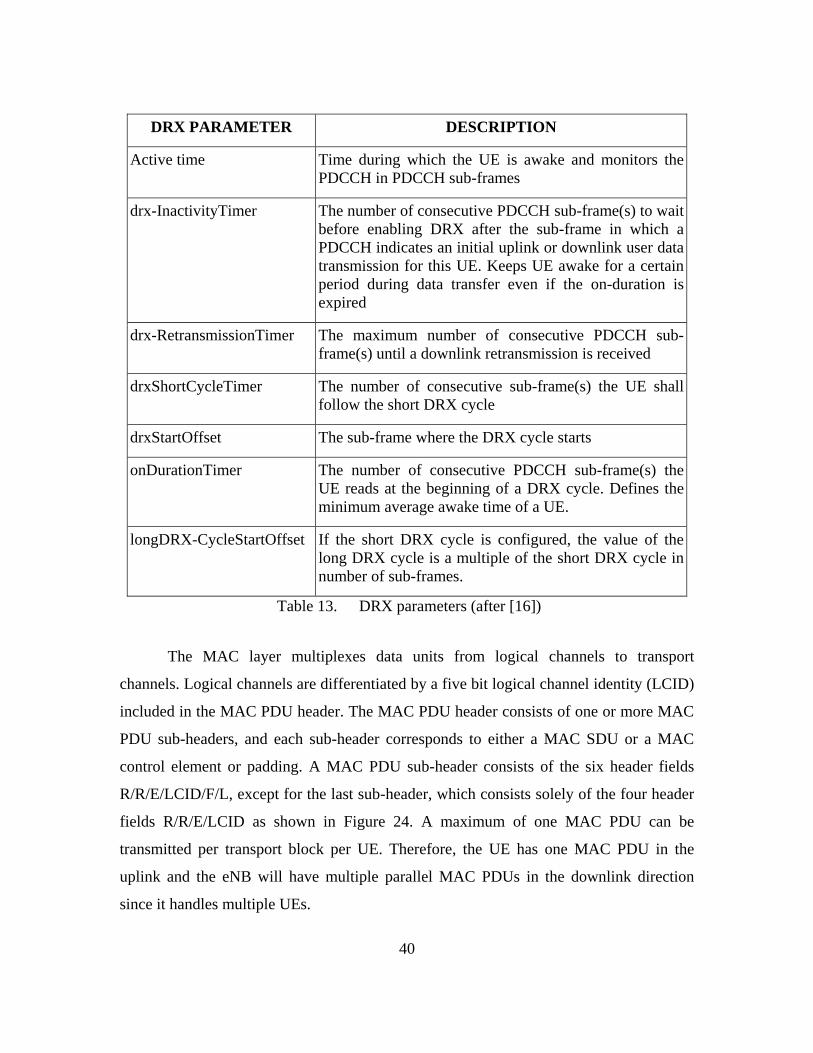
40
DRX PARAMETER DESCRIPTION
Active time Time during which the UE is awake and monitors the
PDCCH in PDCCH sub-frames
drx-InactivityTimer The number of consecutive PDCCH sub-frame(s) to wait
before enabling DRX after the sub-frame in which a
PDCCH indicates an initial uplink or downlink user data
transmission for this UE. Keeps UE awake for a certain
period during data transfer even if the on-duration is
expired
drx-RetransmissionTimer The maximum number of consecutive PDCCH sub-
frame(s) until a downlink retransmission is received
drxShortCycleTimer The number of consecutive sub-frame(s) the UE shall
follow the short DRX cycle
drxStartOffset The sub-frame where the DRX cycle starts
onDurationTimer The number of consecutive PDCCH sub-frame(s) the
UE reads at the beginning of a DRX cycle. Defines the
minimum average awake time of a UE.
longDRX-CycleStartOffset If the short DRX cycle is configured, the value of the
long DRX cycle is a multiple of the short DRX cycle in
number of sub-frames.
Table 13. DRX parameters (after [16])
The MAC layer multiplexes data units from logical channels to transport
channels. Logical channels are differentiated by a five bit logical channel identity (LCID)
included in the MAC PDU header. The MAC PDU header consists of one or more MAC
PDU sub-headers, and each sub-header corresponds to either a MAC SDU or a MAC
control element or padding. A MAC PDU sub-header consists of the six header fields
R/R/E/LCID/F/L, except for the last sub-header, which consists solely of the four header
fields R/R/E/LCID as shown in Figure 24. A maximum of one MAC PDU can be
transmitted per transport block per UE. Therefore, the UE has one MAC PDU in the
uplink and the eNB will have multiple parallel MAC PDUs in the downlink direction
since it handles multiple UEs.

41
Figure 24. Example of MAC PDU (from [16])
There is one LCID field for each MAC SDU, MAC control element or padding
included in the MAC PDU. The defined LCIDs are shown in Figure 25 and Figure 26.
Figure 25. Values of LCID for DL-SCH (from [16])
Figure 26. Values of LCID for UL-SCH (from [16])

42
F. RELATED WORK IN LONG TERM EVOLUTION SECURITY
VULNERABILITIES DURING DISCONTINUOUS RECEPTION PERIOD
It has been suggested in a few LTE security research papers that the long
discontinuous reception (DRX) period is one of several potential security vulnerabilities
in LTE [5], [6]. However, no research has been conducted to show how such an exploit
could actually be conducted during the long DRX period, nor why the LTE DRX
protocol is vulnerable to cyber attacks given its robust security architecture. Part of the
reason may be that the impact of these security vulnerabilities is dependent on the vendor
implementation of DRX algorithms. Currently, most of the Qualcomm based LTE
handsets do not fully implement the connected mode DRX feature [20].
In [5], Fosberg et al. state that the PHY data frame (transport block) is not
encrypted in both the downlink and uplink directions, making it possible for any attacker
with a receiver to detect and read the control (C-PDU) and data (D-PDU) protocol data
units of the RLC/MAC/PDCP sub-layers inside them. They assume that a passive
attacker can understand the PDUs and associate them with the C-RNTIs. Their
assumption that there is no confidentiality or integrity protection at MAC layer but there
is integrity protection on the RRC layer is correct given the information in Table 12. The
C-RNTI and related resource allocation and other PHY control information is transmitted
in the downlink without security during the RACH procedure as explained in Section
II.D.2. Since the same C-RNTI is used by the UE within a tracking area, it would provide
UE presence information for an attacker and a possible way to correlate the C-RNTI with
the user’s service level identity. Fosberg et al. claim that a potential security hole exists
during the DRX period in active mode when the UE keeps its context (e.g., C-RNTI) in
the eNB and is still allowed to transmit packets [5]. They conclude that “an adversary can
inject a C-PDU to the system by using the C-RNTI of a UE in long DRX period,” but not
a D-PDU which is protected by upper layer security mechanisms, “and the cost to launch
this attack is lower than radio jamming attack.” The possible denial of service (DoS)
attack described is shown in Figure 27.

43
Figure 27. Denial of service attack using C-RNTI (from [5])
An attacker can also passively track a UE based on the packet sequence numbers.
As Forsberg et al. state [5],
If the user plane (RLC, PDCP) or control plane (RRC, NAS) packet
sequence numbers are continuous before and after a handover, a passive
attacker can guess the mapping between the old and new C-RNTIs with a
high probability based on the continuity of the packet sequence numbers.
An eNB uses buffer status reports sent by a UE in a C-PDU for packet scheduling,
load balancing, and admission control. Foster et al. claim that during the long DRX
period, an attacker could actively impersonate the UE by sending fake buffer status
reports that report more data to send than are actually buffered. Since the UE does not
send these reports during the long DRX period, the fake buffer status report will not
conflict with real reports from an active UE as shown in Figure 28. As a result, if the eNB
thinks there is congestion in the cell, it may not accept newly arriving UEs. Their
proposed solution to these attacks is a periodic re-allocation of the C-RNTI to make it
more difficult for an attacker to detect if new UEs are arriving or if existing ones are
getting refreshed C-RNTIs. Another proposed solution is ciphering of RRC messages.

44
Figure 28. Successful packet injection attack (from [5])
Seddigh et al. [6] provide a good description of security in LTE and WiMax.
Expanding upon the information in [5], Seddigh et al. suggest two other ways a DoS
attack could be launched using the C-RNTI. The first way against a particular UE could
be accomplished by an attacker intercepting the resource scheduling information and the
C-RNTI to send an uplink control signal at the scheduled time creating a conflict at the
eNB and service problems for the real UE. The second way is by injecting C-PDU
packets during the DRX period to cause DoS attacks against newly arriving users.

45
III. METHODOLOGY
A review of the current Long Term Evolution (LTE) standards at the 3GPP
website and current work in security vulnerabilities was conducted and is summarized in
Section II. Detailed information on the radio resource control (RRC) and discontinuous
reception (DRX) protocols was gathered and analyzed. In this section, a review of the
open source ns-3 network LTE simulator is conducted to ascertain if it can be used to
demonstrate security vulnerabilities in LTE. To verify the results of the simulator, it is
also necessary to analyze captured LTE packet traces and use them as input to the
simulator.
A. DESCRIPTION OF NS-3 OPEN SOURCE NETWORK SIMULATOR
ns-3 is a free discrete-event network simulator, licensed under the GNU GPLv2
license1 and is publicly available for research, development, and educational use [32]. It
is built as a system of open source software libraries primarily developed on GNU/Linux
platforms that work together. ns-3 is distributed as source code, so the target system
needs to have a software development environment to build the libraries first before
building the user programs.
B. DESCRIPTION OF THE LENA MODULE IN NS-3
LENA is a free open source product-oriented LTE/EPC network simulator based
on the ns-3 network simulator.2 The most recent stable version of the LENA code
(version 8) gets periodically merged with the most recent official stable version of ns-3
(ns-3.19) and is available from the ns-3 website. It is actively being used for research
[33].
The following information was found in the manual for LENA [34]. The manual
includes examples of writing simulation programs using ns-3, including configuration of
various LTE and EPC model parameters. LENA supports the femto application platform
1 More information can be found at http://www.gnu.org/copyleft/gpl.html
2 More information can be found at http://networks.cttc.es/mobile-networks/software-tools/lena/

46
interface (FAPI) published by the FemtoForum3 for LTE femtocells. FAPI is a logical
specification only, and its implementation is left to the vendors. The LENA simulator is
designed to be independent from vendor-specific implementations of FAPI.
The LTE-EPC simulation model is shown in Figure 29. The LTE model includes
the radio protocol stack (RRC, PDCP, RLC, MAC, PHY) within the UE and the eNB
nodes. The EPC model includes the core network interfaces, protocols and entities within
the SGW, PGW and MME nodes, and partially within the eNB nodes.
Figure 29. Overview of the LTE-EPC simulation model (from [34])
The LTE model supports evaluation of radio resource management, QoS-aware
packet scheduling, inter-cell interference coordination and dynamic spectrum access. The
architecture of the LTE radio protocol stack model of the UE in the data plane is shown
in Figure 30 and for the control plane in Figure 31. The architecture of the PHY and
channel model of the UE is shown in Figure 32.
The channel model uses the SpectrumChannel interface in the ns-3 spectrum
module. The ns-3 Buildings module is used as a propagation model by indicating the
position of the node (i.e., whether it is indoor or outdoor, and what is its z-axis with
respect to the rooftop level). LENA considers frequency division duplexing (FDD) only
3More information can be found at http://www.smallcellforum.org/resources-technical-papers

47
and implements downlink and uplink propagation separately. A trace-based fading model
is available, but it needs a lot of memory for storing the traces. The LTE PHY model
supports antenna modeling using the ns-3 AntennaModel class with the
IsotropicAntennaModel as the default.
The LTE model includes a random access procedure, as well as the PHY, MAC,
RLC and PDCP protocol layers. It currently supports the output to file of PHY, MAC,
RLC and PDCP level key performance indicators (KPIs).
Figure 30. LTE radio protocol stack model for UE on the data plane (from [34])

48
Figure 31. LTE radio protocol stack model for UE on the control plane (from [34])
Figure 32. LTE PHY and channel model architecture for UE (from [34])

49
The architecture of the LTE radio protocol stack model of the eNB is shown in
Figure 33 and for the control plane in Figure 34. The architecture of the PHY and channel
model of the eNB is shown in Figure 35. The physical layer model includes the inter cell
interference calculation and the simulation of uplink traffic, including both packet
transmission and CQI generation.
Figure 33. LTE radio protocol stack architecture for eNB on the data plane (from [34])
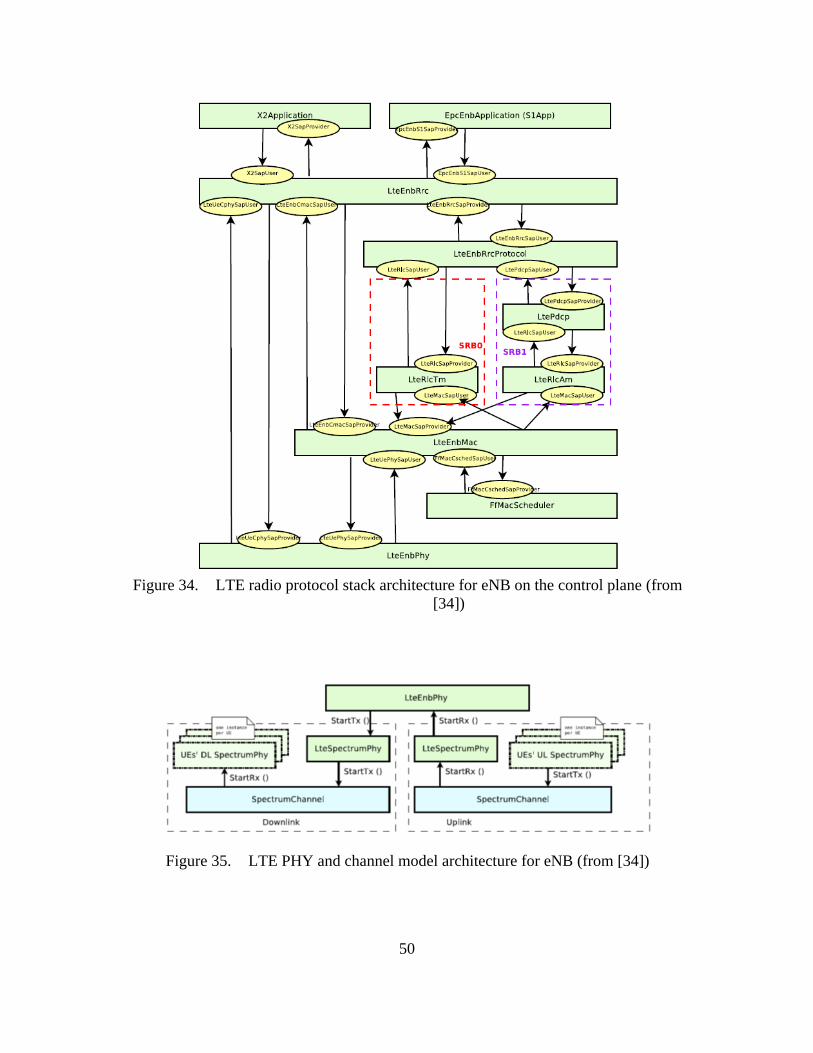
50
Figure 34. LTE radio protocol stack architecture for eNB on the control plane (from
[34])
Figure 35. LTE PHY and channel model architecture for eNB (from [34])

51
In the EPC model, the SGW and PGW functional entities are implemented within
a single node referred to as the SGW/PGW node. Simulation of end-to-end IP
connectivity over the LTE model supporting interconnection of multiple UEs to the
Internet, via a radio access network of multiple eNBs connected to the SGW/PGW node,
is supported. Only IPv4 is supported. X2-based handover between two eNBs and multiple
EPS bearers for each UE can be simulated. The end-to-end LTE-EPC data plane protocol
stack, including the 3GPP S1-U protocol and the LTE radio protocol stack layers, in the
simulator can be seen in Figure 36. The S5 or S8 interfaces are not modeled at all since a
combined SGW and PGW node is used.
Figure 36. LTE-EPC data plane protocol stack in LENA model (from [34])
The architecture of the EPC control plane model is shown in Figure 37. The S1-
AP and the S11 control interfaces are modeled simply as a direct function call between
the two objects. The X2-AP control interface is modeled more accurately using protocol
data units sent over an X2 link.
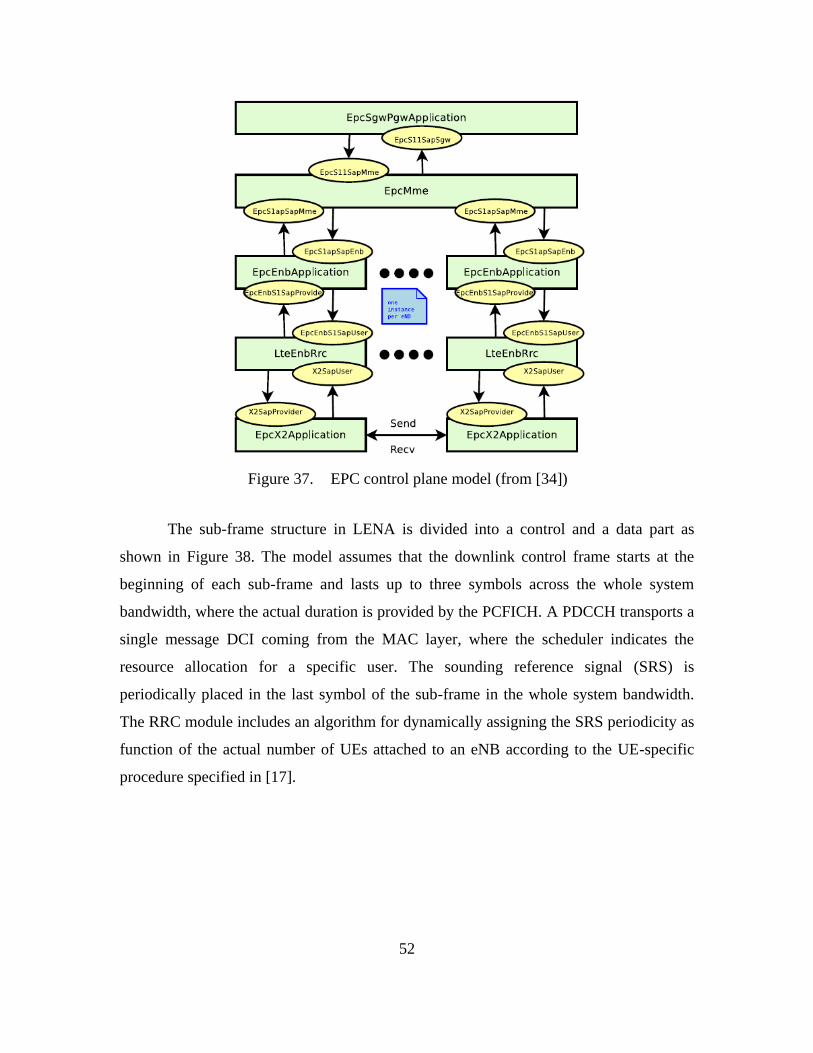
52
Figure 37. EPC control plane model (from [34])
The sub-frame structure in LENA is divided into a control and a data part as
shown in Figure 38. The model assumes that the downlink control frame starts at the
beginning of each sub-frame and lasts up to three symbols across the whole system
bandwidth, where the actual duration is provided by the PCFICH. A PDCCH transports a
single message DCI coming from the MAC layer, where the scheduler indicates the
resource allocation for a specific user. The sounding reference signal (SRS) is
periodically placed in the last symbol of the sub-frame in the whole system bandwidth.
The RRC module includes an algorithm for dynamically assigning the SRS periodicity as
function of the actual number of UEs attached to an eNB according to the UE-specific
procedure specified in [17].

53
Figure 38. LTE sub-frame in LENA (from [34])
The RRC model implemented in the simulator provides the following
functionality:
generation at the eNB and interpretation at the UE of the MIB, SIB1 and
SIB2
initial cell selection
RRC connection establishment procedure
RRC reconfiguration procedure
RRC connection re-establishment, supporting handover

54
C. USER EQUIPMENT DISCONTINUOUS RECEPTION PERIOD
ALGORITHM
There is no standardized DRX algorithm. Table 14 shows a pseudo-code
algorithm that was found for the UE [35].
Table 14. User equipment DRX pseudo-code (from [35])
if (drx-Config == setup) {
if ((Short DRX Cycle is configured/activated) &&
([(SFN * 10) + subframe number] mod (shortDRX_Cycle) ==
(drxStartOffset) mod (shortDRX_Cycle)) {
start onDurationTimer; }
if ((Long DRX Cycle is configured/activated)
&& ( [(SFN * 10) + subframe number] mod (longDRX_Cycle) == (drxStartOffset) ) {
start onDurationTimer; }
if ( (a HARQ RTT Timer expires in this subframe) &&
(data in the soft buffer of the corresponding HARQ process was not successfully decoded)
{
start the drx-RetransmissionTimer for the corresponding HARQ process; }
if ( DRX Command MAC control element is received ) {
stop onDurationTimer;
stop drx-InactivityTimer; }
if ( (drx-InactivityTimer expires) ||
(DRX Command MAC control element is received in this subframe) {
if (the Short DRX cycle is configured ) {
start or restart drxShortCycleTimer;
use the Short DRX Cycle; }
else {
use the Long DRX cycle; }
}
if ( drxShortCycleTimer expires in this subframe ) {
use the Long DRX cycle; }
if ( during the Active Time, for a PDCCH-subframe,
if the subframe is not required for uplink transmission for halfduplex FDD UE operation and
if the subframe is not part of a configured measurement gap) {
monitor the PDCCH;
if (PDCCH indicates a DL transmission ||
DL assignment has been configured for this subframe ) {
start the HARQ RTT Timer for the corresponding HARQ process;
stop the drx-RetransmissionTimer for the corresponding HARQ process; }
if (the PDCCH indicates a new transmission (DL or UL) ) {
start or restart drx-InactivityTimer; }
}
if ( not in the Active Time) {
CQI/PMI/RI on PUCCH and SRS shall not be reported; } }
55
IV. RESULTS
Using an Ubuntu 12.0 Linux desktop virtual machine (VM) within Oracle’s VM
VirtualBox, the tools and current official stable release of the ns-3 network simulator was
downloaded and built successfully using the instructions on the website.4 The tools are
slightly different for download and build of an official release from those to get and build
development copies of ns-3. User programs are written in either the C++ or Python
programming languages and link with ns-3 libraries. The minimal software requirements
to run basic simulations are a gcc/g++ installation of 3.4 or gcc-4.2 or greater, and Python
2.4 or greater. There are functions to visualize the simulations, as well as provide libpcap
traces.
A suite of test programs can be run using a Python script after installation to
ensure it was built correctly. The ns-3 documentation contains a basic tutorial to learn
how to start using it and information on using the LTE module. Example programs can be
used as a starting point for creating one’s own program in a scratch directory or a series
of related programs in a module. There is a very comprehensive tracing mechanism for
debugging and producing output of various parameters from the simulations. In
VirtualBox, a shared folder between the host computer and the ns-3 VM was created to
view and graph simulation output data on the host computer.
A. NS-3 LENA MODEL SIMULATOR LIMITATIONS
The open source ns-3 network simulator was investigated as a tool but it was
found that the LTE model was incomplete and did not include a complete medium access
control protocol or the DRX power saving algorithm in it.
A simplified random access procedure is used in the model, meaning the control
messages do not consume any actual radio resources. A protocol interference model is
used so that whenever two or more identical preambles are transmitted in the same cell
by multiple UEs during the same transmission time interval, neither of these identical
4 Installation instructions and releases of ns-3 can be found at http://www.nsnam.org/

56
preambles will be received by the eNB. This means that the contention resolution part of
the random access procedure is not modeled and the UE assumes random access was
successful once the UE’s MAC receives the random access response from the eNB and
sends the message NotifyRandomAccessSuccessful to the UE’s RRC. Automatic initial
cell selection is only available for EPC-enabled simulations, so LTE-only simulations
must use the manual attachment method with the assumption that the information
contained in the master information block is already known.
The MAC control elements, both header and PDU, are not accurately modeled in
the simulator, only RLC and PDCP PDUs are. As a result, it is not possible to get the
temporary C-RNTI from the MAC PDU. The example simulation program did print out
the C-RNTI in their log file, but it was not obtained from the MAC layer PDU.
The focus of the EPC model is mainly on the data plane and on simulations of
active users in ECM connected mode. Therefore, the EPC control plane is not accurately
modeled as specified by 3GPP. Both radio link failure and the transition to RRC idle
mode from the connected mode are missing in the simulator. Additionally, the RRC
connection release in the simulator is currently never triggered by the EPC or by the
NAS. This is unfortunate since RRC connection release is required by the DRX protocol
in the RRC_IDLE State. The long DRX procedure also gets triggered when the UE
switches from RRC connected to RRC idle modes, which is not implemented.
Security related aspects are not modeled, therefore SRB1 is always used and
SRB2 is never activated since SRB2 is always configured by the E-UTRAN after security
activation. The NAS model does not support any location update/paging procedure in idle
mode, something also needed for the DRX mode.
B. LIMITATIONS OF LONG TERM EVOLUTION TRACES
The NPS Electrical Engineering department has packet traces from LTE captured
using the commercially available Sanjole Wavejudge software. The free Wireshark
network protocol analyzer tool indicates a capability to decode the LTE medium access
control, radio link control and packet data convergence protocol headers if LTE packet

57
traces are captured using the dissectors for those headers. However, very little evidence
was available of anyone having used it successfully.
The NPS traces were not in the libpcap file format required by Wireshark and
neither was the power saving algorithm used when the traces were recorded. As a result,
it was not possible to decode the traces and demonstrate that the security protocols were
weak during the attach procedure or during the power saving mode.

58
THIS PAGE INTENTIONALLY LEFT BLANK

59
V. CONCLUSIONS AND FUTURE WORK
A. CONCLUSIONS
Most researchers have focused on improving LTE’s performance and efficiency
for the past ten years and have only recently started investigating the security
vulnerabilities of LTE [5], [6], [27], [28], [36], [37]. The development of the LTE
standards have taken into account the security deficiencies of prior generations of
wireless communications technologies, but some researchers have theorized cyber attacks
could still occur in LTE during times when those security protocols are either inactive or
weak. Both [27] and [6] present a comprehensive survey of security architecture,
vulnerabilities and solutions in LTE and LTE-A networks. The specific vulnerabilities in
LTE often mentioned include illegal use of user and mobile equipment, location tracking,
denial of service attacks and data integrity attacks. However, none of the researchers have
provided any experimental data to support the claims of such vulnerabilities.
It has been suggested in some LTE security research papers that the long DRX
period is one of several potential security vulnerabilities in LTE [5], [6]. Analysis of LTE
standards in Section II revealed that the user’s equipment can be vulnerable to a cyber
attack during the network attach mode, or during the long-term power saving mode,
because security protocols are either inactive or weak. It is hypothesized that if one
obtains the user identity information sent in the clear during network attach, it could then
be used to conduct a denial of service or data integrity attack during the long-term power
saving mode.
As discussed in Section IV, the open source ns-3 network simulator was
investigated as a tool to demonstrate the exploit, but it was found that the LTE model was
incomplete and did not include the complete MAC protocol or the DRX power saving
algorithm. Next, analysis of captured LTE packet traces available at NPS was considered.
The Wireshark network protocol analyzer tool indicates a capability to decode the LTE
medium access control, radio link control and packet data convergence protocol headers
if LTE packet traces are captured using the dissectors for those headers. However, the

60
NPS LTE packet traces available were not in the libpcap file format required by
Wireshark and neither was the power saving algorithm in effect when the traces were
recorded by the commercially available Sanjole Wavejudge software. As a result, it was
not possible to analyze if the security protocols were weak during the attach procedure or
during the power saving mode.
Several limitations of the currently available tools have made it difficult to test the
hypothesis at this time. Empirical data from actual measurements of LTE network traffic
with the DRX algorithm is needed to analyze and design an efficient mechanism for
using a UE’s C-RNTI during the long DRX period in a cyber attack. The LTE standards
have parameters defined for DRX but do not specify how to implement the algorithm. In
fact, very few device vendors have implemented DRX, though many currently have plans
to do so in the future. Appropriate laboratory testing equipment and software for
analyzing LTE signals are required to demonstrate a cyber attack in LTE, both of which
were not available at the time of this thesis.
B. FUTURE WORK
In order to successfully demonstrate the vulnerability of LTE to cyber attacks
during the long DRX period in the future, several issues need to be resolved.
First of all, algorithms for DRX at the UE, eNB and MME need to be developed
and standardized. Currently, most of the Qualcomm based LTE handsets do not fully
implement the connected mode DRX feature [20], but it is not known if they implement
the idle mode DRX feature. The LTE standards have provided for the DRX parameters to
be exchanged between the UE, eNB and MME, but have left it up to the device vendors
to implement the algorithm themselves. No open source implementations of DRX
algorithms were found, indicating that they will be proprietary algorithms developed by
the vendors. Without standardization of the algorithms, one would have to take into
account which vendor’s equipment is being used, complicating the simulations. There are
currently a lot of researchers investigating efficient DRX algorithms [38].
Second, in order to use the open source ns-3 network simulator, programs for the
transition from RRC connected to idle modes, the DRX algorithms and the AS security

61
mode command procedure would all need to be added. From discussions with the
maintainers of ns-3, the conclusion was that it would take someone working full-time a
couple of years to add all that code to the ns-3 simulator.
Finally, it would be worthwhile to investigate capturing actual traces of LTE
packets for analysis using Wireshark’s dissectors for LTE medium access control, radio
link control and packet data convergence protocol headers. Without those dissectors,
trying to decode the packets is extremely difficult, if not impossible. The captured LTE
traces are also needed to ensure validity of the LTE module in the ns-3 network
simulator.

62
THIS PAGE INTENTIONALLY LEFT BLANK

63
LIST OF REFERENCES
[1] “Digital government: Building a 21st century platform to better serve the
American people.” (2012). Federal Chief Information Officers Council,
Washington, DC. [Online]. Available:
http://www.whitehouse.gov/sites/default/files/omb/egov/digital-
government/digital-government-strategy.pdf
[2] “Department of Defense mobile device strategy.” (2012). Department of Defense,
Washington, DC. [Online]. Available:
http://www.defense.gov/news/dodmobilitystrategy.pdf
[3] “Implementing a Nationwide, Broadband, Interoperable Public Safety Network in
the 700 MHz Band.” (2011). Federal Communications Commission, Washington,
DC. [Online]. Available: http://www.gpo.gov/fdsys/pkg/FR-2011-08-
18/html/2011-20831.htm
[4] “Long term evolution protocol overview.” (2008). Freescale, Austin, TX,
Whitepaper. [Online]. Available:
http://www.freescale.com/files/wireless_comm/doc/white_paper/LTEPTCLOVW
WP.pdf
[5] D. Forsberg et al., “Enhancing security and privacy in 3GPP E-UTRAN radio
interface,” in 18th International Symposium on Personal, Indoor and Mobile
Radio Communications, Athens, Greece, 2007.
[6] N. Seddigh et al., “Security advances and challenges in 4G wireless networks,” in
Eighth Annual International Conference on Privacy Security and Trust (PST),
Ottawa, Ontario, 2010.
[7] 3GPP System Architecture Evolution (SAE); Security architecture, 3GPP
Technical Specification 33.401, version 11.7.0, 2013.
[8] M. Nohrborg. (2013, September). “LTE overview.” [Online]. Available:
http://www.3gpp.org/technologies/keywords-acronyms/98-lte
[9] F. Firmin. (2013, November). “The evolved packet core.” [Online]. Available:
http://www.3gpp.org/technologies/keywords-acronyms/100-the-evolved-packet-
core
[10] General Packet Radio Service (GPRS) enhancements for Evolved Universal
Terrestrial Radio Access Network (E-UTRAN) access, 3GPP Technical
Specification 23.401, version 10.10.0, 2013.

64
[11] Evolved Universal Terrestrial Radio Access Network (E-UTRAN); Architecture
description, 3GPP Technical Specification 36.401, version 11.2.0, 2013.
[12] “LTE Tutorial.” (2013). [Online]. Available:
http://www.tutorialspoint.com/lte/index.htm
[13] M. Lindström, “LTE-Advanced radio layer 2 and RRC aspects,” in 3GPP LTE-
Advanced Evaluation Workshop, Beijing, China, 2009.
[14] Evolved Universal Terrestrial Radio Access (E-UTRA); Physical channels and
modulation, 3GPP Technical Specification 36.211 version 11.4.0, 2013.
[15] “3GPP LTE channels and MAC layer.” (2009).
- -
[16] Evolved Universal Terrestrial Radio Access (E-UTRA); Medium Access Control
(MAC) protocol specification, 3GPP Technical Specification 36.321 version
11.3.0, 2013.
[17] Evolved Universal Terrestrial Radio Access (E-UTRA); Physical layer
procedures, 3GPP Technical Specification 36.213, version 11.4.0, 2013.
[18] “LTE identifiers.” (2011). NMC Consulting Group, Seoul, Korea. [Online].
Available:
http://www.nmcgroups.com/files/download/NMC.LTE%20Identifiers.v1.0.pdf
[19] Evolved Universal Terrestrial Radio Access (E-UTRA) and Evolved Universal
Terrestrial Radio Access Network (E-UTRAN); Overall description; Stage 2,
3GPP Technical Specification 36.300, version 11.7.0, Sept. 2013.
[20] A. Basir. (2013). “3GPP Long Term Evolution (LTE).” [Online]. Available:
http://4g-lte-world.blogspot.com/
[21] Evolved Universal Terrestrial Radio Access (E-UTRA); Radio Resource Control
(RRC); Protocol specification, 3GPP Technical Specification 36.331, version
11.5.0, Sept. 2013.
[22] A. Roessler. (2013, September). “Test ANR functionality on your LTE devices.”
[Online]. Available: http://electronicdesign.com/test-amp-measurement/test-anr-
functionality-your-lte-devices
[23] Evolved Universal Terrestrial Radio Access (E-UTRA); Radio Resource Control
(RRC); Protocol specification, 3GPP Technical Specification 36.331, version
11.5.0, 2013.
[24] F. Firmin. (2013, November). “Non-access stratum (NAS).” [Online]. Available:
http://www.3gpp.org/technologies/keywords-acronyms/96-nas
65
[25] Shisenchi. (2012, February). “Random access procedure in LTE.” [Online].
Available: http://www.teletopix.org/4g-lte/random-access-procedure-in-lte/
[26] M. Lazhar Belhouchet and M. Hakim Ebdelli, “Session 6: LTE/SAE mobility and
session management,” in ITU/BDT Arab Regional Workshop on 4G Wireless
Systems, Tunisia, 2010.
[27] C. B. Sankaran, “Network access security in next-generation 3GPP systems: A
Tutorial,” IEEE Communications Magazine, vol. 47, no. 2, Feb. 2009.
[28] J. Cao et al., “A survey on security aspects for LTE and LTE-A networks,” IEEE
Communications Surveys and Tutorials, vol. PP, no. 99, April 2013.
[29] C. Bontu and E. Illidge, “DRX mechanism for power saving in LTE,” IEEE
Communications Magazine, June 2009.
[30] P. Jodukallu. (2013, December). “Basic LTE.” [Online]. Available:
http://lteshare.blogspot.com/2013/12/DRx.html
[31] Evolved Universal Terrestrial Radio Access (E-UTRA) and Evolved Packet Core
(EPC); User Equipment (UE) conformance specification; Part 2: Implementation
Conformance Statement (ICS) proforma specification, 3GPP Technical
Specification 36.523-2, version 8.5.0, 2010.
[32] “ns-3 web page.” (2014). [Online]. Available: http://www.nsnam.org/
[33] N. Baldo et al., “A new model for the simulation of the LTE-EPC data plane,” in
International Conference on Simulation Tools and Techniques (SIMUTools),
Desenzano, Italy, 2012.
[34] “The LENA ns-3 LTE module documentation release v8.” (2014, Jan.). Centre
Tecnològic de Telecomunicacions de Catalunya. [Online]. Available:
http://networks.cttc.es/mobile-networks/software-tools/lena/
[35] “MAC.” (2014, May). [Online]. Available:
http://www.sharetechnote.com/html/MAC_LTE.html#DRX
[36] M. Aiash et al., “Providing security in 4G systems: Unveiling the challenges,” in
Sixth Advanced International Conference on Telecommunications (AICT),
Barcelona, May 2010.
[37] Y. Park and T. Park, “A survey of security threats on 4G Networks,” in Globecom
Workshops, Washington, DC, Nov. 2007.
[38] Y. Mihov et al., “Analysis and performance evaluation of the DRX mechanism
for power saving in LTE,” in 26th Convention of Electrical and Electronics
Engineers in Israel (IEEEI), Eliat, Israel, Nov. 2010.

66
THIS PAGE INTENTIONALLY LEFT BLANK

67
INITIAL DISTRIBUTION LIST
1. Defense Technical Information Center
Ft. Belvoir, Virginia
2. Dudley Knox Library
Naval Postgraduate School
Monterey, California