
Naomi GD-Rom System Universal Kit - MameChannel.it · JAMMA VIDEO STANDARD adopted by NAOMI is...
31
1ST PRINTING DEC. 00 MANUAL NO. 999-1118 SEGA ENTERPRISES, INC. USA Universal Kit Kit Installation Instructions & Service Manual Switchable FROM High Resolution 31K TO Standard (Low) Resolution 15.75K. 2 PLAYER GAME (2) 8-Way Joystick per player (2) Action Buttons per player (1) Start Button per player for a Horizontal Monitor Kit come with one (1) JVS/JAMMA Interface Board for two (2) Player Action. Naomi GD-Rom System
Transcript of Naomi GD-Rom System Universal Kit - MameChannel.it · JAMMA VIDEO STANDARD adopted by NAOMI is...

1ST PRINTING DEC. 00
MANUAL NO. 999-1118
SEGA ENTERPRISES, INC. USA
Universal KitKit Installation Instructions
& Service Manual
Switchable FROM High Resolution 31K
TO Standard (Low) Resolution 15.75K.
2 PLAYER GAME
(2) 8-Way Joystick per player
(2) Action Buttons per player
(1) Start Button per player
for a Horizontal Monitor
Kit come with one (1) JVS/JAMMA Interface Board
for two (2) Player Action.
Naomi GD-Rom System

Warranty
Your new Sega Product is covered for a period of 90 days from the date of shipment. This certifiesthat the Printed Circuit Boards, Power Supplies and Monitor are to be free of defects in workman-ship or materials under normal operating conditions. This also certifies that all Interactive ControlAssemblies are to be free from defects in workmanship and materials under normal operating condi-tions. No other product in this machine is hereby covered.
Sellers sole liability in the event a warranted part described above fails shall be, at its option, toreplace or repair the defective part during the warranty period. For Warranty claims, contact yourSega Distributor.
Should the Seller determine, by inspection that the product was caused by Accident, Misuse, Ne-glect, Alteration, Improper Repair, Installation or Testing, the warranty offered will be null and void.
Under no circumstances is the Seller responsible for any loss of profits, loss of use, or other dam-ages.
This shall be the exclusive written Warranty of the original purchaser expressed in lieu of all otherwarranties expressed or implied. Under no circumstance shall it extend beyond the period of timelisted above.

1
1P
Start Sw.
8-WaysSW2
SW1
PLAYER 1
2P
8-WaysSW2
SW1
PLAYER 2
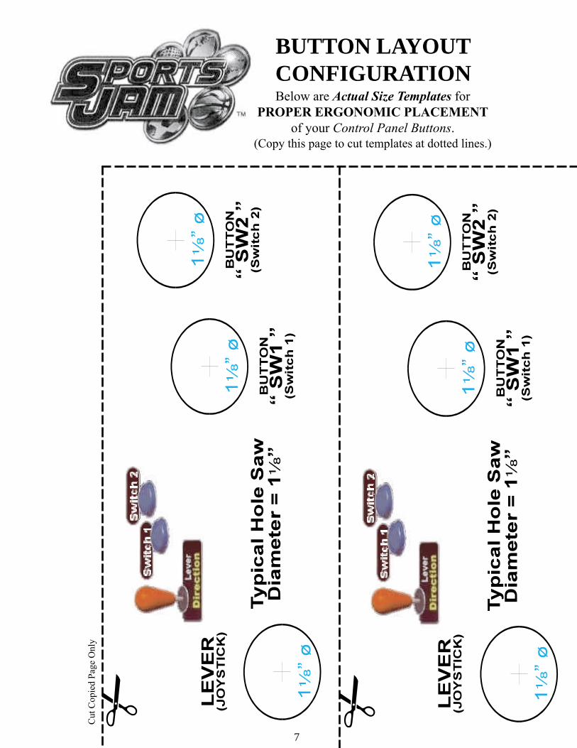
Button Layout Overview
(See Templates on Page VII)
FIG. 1Kit Overview
Transformer
Audio Board
Power Supply
Volume/Speaker/Coin MeterCable
JVS/JAMMAInterface Board
AC PowerCable
(GRN/WHT& BLK)
GD-ROM
VGA Output
JVS USB Port
Service Switches

2
INSTALLATION INSTRUCTIONS
1) First. Remove all access panels from the game. Locate the original game Logic PCB’s & Power
Supply and remove from the Cabinet by first disconnecting all harnesses from the boards. (You need
only to splice in the Main Power (110v AC) into the 3-Pin Connector (GRN/WHT/BLK).)
2) Remove all existing game harnesses (we suggest using New Jamma Harnesses (NOT contained in the
kit) to ensure reliability).
3) Locate the most convenient and open area of the cabinet to mount the Sports Jam GD-Rom System
Asm. Make sure this area is free and clear of all cable harnesses and grounds, cable clamps, etc. (See
FIG. 1, inside cover).
Vacuum out or clean bottom of cabinet of dirt & miscellaneous parts (e.g.
screws, loose coins / tokens, etc.).
Remove all exterior decals and repair any cabinet damage. Repaint
cabinet if necessary. Remove the Monitor Plexi or if your game plexi has
Silk-screened artwork, you will need to strip it off.
4) Connect the JAMMA Harnesses to the JVS-JAMMA Interface Boards. Separate the wires from each
other (i.e. Control Panel, Video, Speaker, Power Supply). Run the various harnesses to the part of the
cabinet they go to ensuring they are dressed properly & secured to the cabinet. (See FIG. 4 Pg. iv).
Locate the Volume/Speaker/Coin Meter Cable and connect to your existing Diag. Switch Bracket or
use the new one included with the kit. (See FIG. 3, Pg. iii). Note: If you are using a VGA
Compatible Monitor you can run your VGA Cable directly to the monitor or connect it to your JVS
JAMMA Interface for RGB Conversion to your JAMMA Cables.
5) Remove Marquee from cabinet and cut to fit the new Sports Jam Marquee in place.
Sports Jam uses 1 Lever (Joystick) with 2 Multi-Function Switches
(Buttons) for controls and a Start Button per player. REPLACE old
Joysticks & Buttons with the NEW ones supplied in Kit.
6) First remove all Joystick and Button assemblies from the Control Panel. Remove Lexan and Control
Panel Overlay. Proceed to clean surface of the Control Panel by removing all adhesive and dirt. Fill
in or plug up existing button holes to set up a blank work area for your (1 - 2) templates (See Pages
VII, COPY & CUT).
7) Carefully tape template on the Control Panel in configuration of 2 players; using a Center Punch,
mark your hole centers. With a 1c” Hole - Saw, proceed to drill out holes for the new Control Panel
configuration. Once drilling is complete, clean surface once again eliminating all wood chips and
dust.
8) Install the new Control Panel Overlay by carefully peeling off the paper backing and laying down on
the panel. Smooth it out, starting in the center and working your way to the edges (removing all of
the trapped air pockets). If necessary, cut the edges of the overlay excess and fold under panel.
9) Cut out the button and Joystick Holes. Install Joystick and buttons from kit into the Control Panel
and tighten down. Connect all game harness wires to switches and buttons.
3
INSTALLATION INSTRUCTIONS
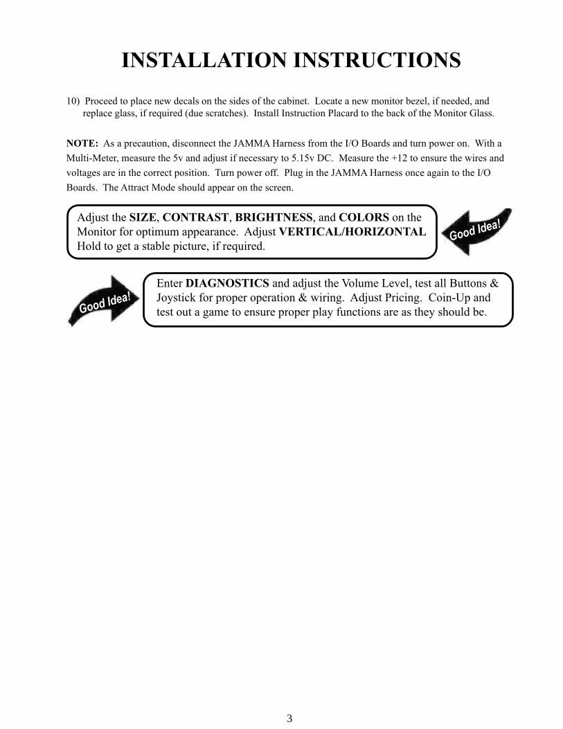
10) Proceed to place new decals on the sides of the cabinet. Locate a new monitor bezel, if needed, and
replace glass, if required (due scratches). Install Instruction Placard to the back of the Monitor Glass.
NOTE: As a precaution, disconnect the JAMMA Harness from the I/O Boards and turn power on. With a
Multi-Meter, measure the 5v and adjust if necessary to 5.15v DC. Measure the +12 to ensure the wires and
voltages are in the correct position. Turn power off. Plug in the JAMMA Harness once again to the I/O
Boards. The Attract Mode should appear on the screen.
Adjust the SIZE, CONTRAST, BRIGHTNESS, and COLORS on the
Monitor for optimum appearance. Adjust VERTICAL/HORIZONTAL
Hold to get a stable picture, if required.
Enter DIAGNOSTICS and adjust the Volume Level, test all Buttons &
Joystick for proper operation & wiring. Adjust Pricing. Coin-Up and
test out a game to ensure proper play functions are as they should be.

4
Coin Meter
Test Service
Volume JAMMA Pin R
JAMMA Pin 15JAMMA Pin 1
Yellow Wire from ExtraHarness (+5v)
JAMMA Pin 8
+_
Pin 1
Pin 5
Pin 4
To CN1 ofAmplifier Board
YE
L/R
ED
WH
T/R
ED
GR
N/R
ED
From CN2 ofAmplifier Board
From CN4 ofAmplifier Board
GRY/RED
ORG/RED
ORG/BLUE
GRY/BLUE
LeftSpeaker
RightSpeaker
Sega Naomi System SwitchBracket and SpeakerInstallation Diagrams
(Figure 3)
5
4
1
2
3
5
6
7
8
10
11
12
13
14
15
16
17
1819
20
21
A
B
C
D
E
F
H
J
K
L
M
N
P
R
S
T
U
V
X
Y
Z
a
22
23
24
4
e
d26
25 c
b
28 f
27
9
W
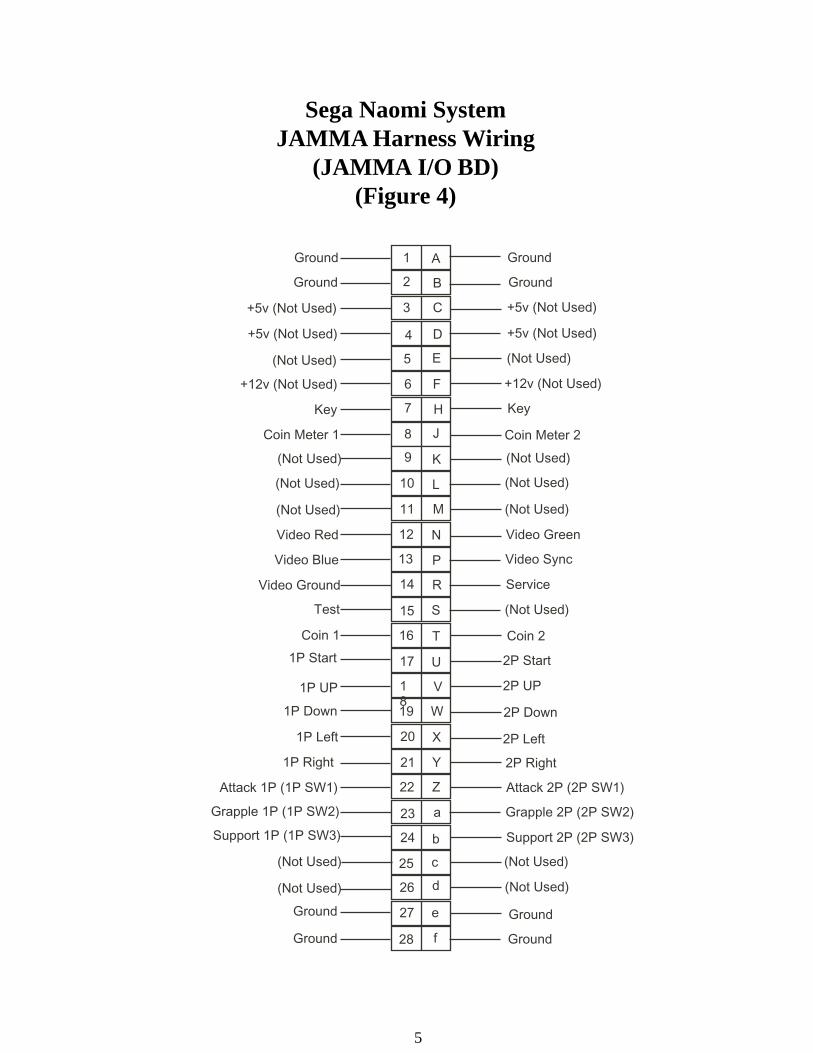
Ground
Ground
Ground
Ground
+5v (Not Used) +5v (Not Used)
+5v (Not Used) +5v (Not Used)
(Not Used) (Not Used)
+12v (Not Used) +12v (Not Used)
Key Key
Coin Meter 1 Coin Meter 2
(Not Used)
(Not Used)
(Not Used)
(Not Used)
(Not Used)
(Not Used)
Video Red
Video Blue
Video Ground
Video Green
Video Sync
Service
Test (Not Used)
Coin 1 Coin 2
1P Start 2P Start
1P UP 2P UP
2P Down1P Down
1P Left 2P Left
1P Right
Attack 1P (1P SW1)
Grapple 1P (1P SW2)
Support 1P (1P SW3)
Ground
Ground
2P Right
Attack 2P (2P SW1)
Ground
Ground
Support 2P (2P SW3)
Grapple 2P (2P SW2)
(Not Used)
(Not Used)
(Not Used)
(Not Used)
Sega Naomi SystemJAMMA Harness Wiring
(JAMMA I/O BD)(Figure 4)

6
CN4
Sega Naomi SystemFilter Board Information
Connector Description etc.
PSW2 PSW1
CN3CN2 CN1
DIPSW1
Power ConnectorsVGA LevelVideo Out
Preamp LevelAudio Out
Test Switch
ServiceSwitch
1
1
2
2
3
3
4
Setting for HighResolution 31KHZ1 -4 off
Setting for StandardResolution 15KHZ1 on 2-4 off.
7
Cut
Copie
d P
age
Only
BUTTON LAYOUTCONFIGURATIONBelow are Actual Size Templates for
PROPER ERGONOMIC PLACEMENT
of your Control Panel Buttons.
(Copy this page to cut templates at dotted lines.)

8
THIS PAGE INTENTIONALLY BLANK

9
When using the cabinet that shares the coin chute between 1P and2P (such as the NAOMI CABINET, BLAST CITY, etc.), changethe setting of the COIN CHUTE TYPE item in the COINASSIGNMENTS screen, from INDIVIDUAL to COMMON.Using these cabinets with the setting of INDIVIDUAL disables toplay from the 2P side.For more information about the COIN ASSIGNMENTS screen,see the Naomi Service Manual.When having connected the power for the first time, open theSYSTEM MENU - GAME TEST MODE - INPUT TEST screenand test the input devices; thereby make sure that they canfunction normally.This game is available only with the NAOMI GD-ROM system. Itis not available with other hardware.This game cannot support the competitor connection kit of theNAOMI CABINET. When connecting the wire to the controlpanel, therefore, connect it only to a single I/O board.
BEFORE USING THE PRODUCT, BE SURE TO READ THE FOLLOWING:
1. HANDLING PRECAUTIONS .................................................................................... 12. SPECIFICATIONS ...................................................................................................... 23. CONTENTS OF GAME .............................................................................................. 34. TEST MODE ................................................................................................................ 7 A.SYSTEM MENU B.GAME TEST MODE a.INPUT TEST Switch input test is performed. b.GAME ASSIGNMENTS Various settings such as game difficulty, etc. can be set. c.BOOKKEEPING Allows for checking data such as the number of coins inserted, operation time, game time, etc. d.BACKUP DATA CLEAR Clears the contents of BOOKKEEPING.5. GAME BOARD ......................................................................................................... 146. SOFT KIT ................................................................................................................... 16
TABLE OF CONTENTS
Use of this product is unlikely to cause physical injuries or damages toproperty. However, where special attention is required this is indicated by athick line, the word "IMPORTANT" and its sign in this manual.
Indicates that mishandling the product by disregarding thisdisplay can cause the product's intrinsic performance not to beobtained, resulting in malfunctioning.
STOP
IMPORTANT
STOP
IMPORTANT

10
To prevent electric shock or IC Board malfunctioning, be sure toturn off the power for the cabinet when installing or removing theIC Board.
Extraneous matter such as dust on the IC Board can cause the ICBoard to generate heat and result in a fire due to short circuit, etc.Ensure the IC Board surfaces are always kept clean.
Use NAOMI for the cabinets compatible with JVS. UsingNAOMI for the cabinet other than those compatible with JVS cancause generation of heat and a fire.
Be sure to connect the IC Board and connectors completely.Insufficient insertion can damage IC Board, etc.
For the IC Board circuit inspection, only the use of Logic Tester ispermitted.The use of ordinary testers is not permitted as these can damagethe IC Board.
Do not subject the IC Board to static electricity when installing theIC Board in the cabinet or when connecting wire harnessconnectors to the IC Board.
When soldering buttons, etc. to the wire harnesses, be sure toremove the wire harnesses from the IC Board so as not to subjectthe IC Board to heat.
Using NAOMI without the Shield Case can cause electric wavetrouble. Be sure to use NAOMI together with the accessory ShieldCase.
The monitor frequency corresponding to NAOMI is 15kHz or31kHz.NAOMI can not be used for the cabinet incorporating a monitor orprojector not corresponding to 15kHz or 31kHz.
1. HANDLING PRECAUTIONS
STOP
IMPORTANT
Concerning the display of JAMMA VIDEO STANDARD:JAMMA VIDEO STANDARD adopted by NAOMI is referred to as JVS. Asagainst this Standard, the conventional JAMMA STANDARD which employs56P Edge Connectors adopted by ST-V, etc. is displayed as Old JAMMASTANDARD.
The specific Manual attached to each game sometimes displays JVS as JVSTANDARD, New JAMMA STANDARD, or JAMMA 2 STANDARDAGAINST OLD JAMMA STANDARD as JAMMA STANDARD, JS, etc.
The contents herein described are subject to change without notice.

11
8WAYS
SW1
SW2
START SW
1P 2P
8WAYS
SW1
SW2
Minimum DIMM Memory Capacity
256 MB
PLAYER 1 PLAYER 2
2. SPECIFICATIONS
ON-SCREEN DISPLAY
Monitor Position
Synchronous Frequency15/31 kHz
CONTROL PANEL
HORIZONTAL
1
2
3

12
3. HOW TO PLAY THE GAME
A player plays the most popular sports in the world (8 events and 12 games). Theplayer aims to take first money and thereby to be designated as a KING OFSPORTS.
Following the 3 stages, a player ventures to play the events, one each on a stage.Then the player moves to a final stage and chooses the best event out of the finished3 events so as to be designated a KING OF SPORTS.
First Stage
Second Stage
Third Stage
Final Stage
(KING OF SPORTS)
Aims to be designated as a KING OF SPORTS.
Selects and plays an event.
Selects and plays an event.
Selects and plays an event.
Selects an event out of the finished3 events and plays it.
Introduction to the Game
Stages toward a KING OF SPORTS

13
The player tries toshoot, within a limitedtime, from the 5positions in the three-point field.
The player tries to hit ahome run into anoutfield stands.
The two players try tocompete for atouchdown.
The player tries to teeoff the ball nearest tothe pin.
The player tries toscore a goal with along shoot.
The player tries toreceive the ball backinto the target in thedisplayed court.
The two players try torally.
The player tries toscore a goal with adirect shoot.
Games and Operation (1)

14
The player tries tosprint around the tracktwo times for theshortest time.
The player tries to putt.
The player tries toscore a field goal.
The player, as a goalie,tries to save the shotsas many as possible.
Special CommandA special command is available to enable a player to select all the
games at the beginning (not one stage by one stage).
To activate the special command:
When a shutter is going to open after the coins have been inserted,
move the control stick upward, downward, rightward, and leftward,
and then press the SW1 and SW2 switches - all in this order.
Games and Operation (2)

15
When in a 1-person play:
The game is over if the player fails to satisfy the clearing condition within aspecified time interval.
When in a 2-person play:
The player who has won the two matches is a winner.If both the players have equal scores, the result of the game is decided with asudden death rule. (If the result can not be decided even with a sudden death rule,the game is over.)
Indicates a
second player.
Indicates a
present stage.
Indicates a
clearing condition.
Indicates points
of the game.
Indicates a remaining time.
Indicates a first player.
Indicates a
present stage.
Indicates a
remaining time.
Indicates the
number of wins.
Instructions on the Screen
Indicates a total
of prize money.
Indicates the number of credits.

16
This test mode mainly allows the IC Board to be checked for accurate functioning,monitor color to be adjusted as well as COIN ASSIGNMENTS and GAMEASSIGNMENTS to be adjusted.
1) Connect the power, and press the test button. Then the following SYSTEMMENU screen appears.
2) Press the service button to move the -> mark to any desired item, and press thetest button.
3) Press the service button to move the -> mark to GAME TEST MODE item, andpress the test button. Then the GAME TEST MENU screen appears thatenables to test the items specific to this game. For the details, see the followingpages.
4) After testing, select the EXIT and press the test button. The game advertisingscreen reappears.
NOTE: For more information about the SYSTEM MENU screen, see theGD-ROM Service Manual (No.: 420-6620-01).
4. TEST MODE
A. SYSTEM MENU
When settings are changed in SYSTEM ASSIGNMENTS, COIN
ASSIGNMENTS, and GAME ASSIGNMENTS of GAME TEST MODE,
be sure to exit from the test mode of SYSTEM MENU screen. The contents
of setting changes are stored in the IC on the BOARD when exiting from the
Test Mode. If the power is turned off in the Test Mode (before exiting), the
contents of setting changes are ineffective. In this case, the settings remain
unchanged.
STOP
IMPORTANT
SYSTEM MENU
RAM TEST JVS TEST SOUND TEST C.R.T. TEST SYSTEM ASSIGNMENTS COIN ASSIGNMENTS BOOKKEEPING BACKUP DATA CLEAR CLOCK SETTING
DIMM BOARD TEST GAME TEST MODE [XXXXXXXXX ]
-> EXIT
SELECT WITH SERVICE BUTTON AND PRESS TEST BUTTON
12
31
23
14
44
24
44
43
In the SYSTEM ASSIGNMENTS,CABINET TYPE is set to 2 PLAYER(S),MONITOR TYPE is set to HORIZONTAL,and SERVICE TYPE is set to COMMON.
COIN ASSIGNMENTS initial settings as follows:COIN CHUTE TYPE: COMMONCOIN/CREDTI SETTING: #1COIN CHUTE #1 (#2): 1 COIN 1 CREDIT
SEQUENCE SETTING of COIN ASSIGNMENTS functions as follows:SEQUENCE 1: Number of credits required for game start (initial value = 1 CREDIT).SEQUENCE 2: Number of credits required for CONTINUE (initial value = 1 CREDIT)SEQUENCE 3 ~ 8: NOT USED.
MEANING OF DISPLAY IN BOOKKEEPING 2/2P1 (P2) SEQ 1: Play frequency of Player 1 (Player 2)P1 (P2) SEQ 2: Frequency of CONTINUE by Player 1 (Player 2).P1 (P2) SEQ 3 ~ 8: NOT USED.

17
B. GAME TEST MODE
GAME TEST MENU Screen
Press the service button to move the -> mark to any desired item, and press thetest button. Then the corresponding screen appears.
After testing, select the EXIT and press the test button. Then the SYSTEMMENU screen reappears.
GAME TEST MENU
INPUT TEST GAME ASSIGNMENTS BOOKKEEPING BACKUP DATA CLEAR
-> EXIT
SELECT WITH SERVICE BUTTON AND PRESS TEST BUTTON

18
a. INPUT TEST
This screen tests the input devices. Make sure that each of the input devices canchange its indication from OFF to ON as you operate the corresponding device.
After testing, press the test button and the service button simultaneously. Then theGAME TEST MENU screen reappears.
INPUT TEST
START1 : OFF START1 : OFFSW_SHOT10 : OFF SW_SHOT20 : OFFSW_SHOT11 : OFF SW_SHOT21 : OFF
SW_UP1 : OFF SW_UP2 : OFFSW_DOWN1 : OFF SW_DOWN2 : OFFSW_LEFT1 : OFF SW_LEFT2 : OFFSW_RIGHT1 : OFF SW_RIGHT2 : OFFTEST-SW : OFF SERVICE-SW : OFF
PRESS SERVICE BUTTON AND TEST BUTTON TO EXIT
INPUT TEST Screen
CONTROL PANEL

19
b. GAME ASSIGNMENTS
This screen sets the game difficulty level.Press the service button to move the -> mark to the GAME DIFFICULTY item,and press the test button. Then the GAME DIFFICULTY item can change itsindication between VERY EASY, EASY, MEDIUM EASY, NORMAL, BITHARD, MEDIUM HARD, HARD, and VERY HARD.
GAME ASSIGNMENTS
GAME DIFFICULTY NORMAL
-> EXIT
SELECT WITH SERVICE BUTTON AND PRESS TEST BUTTON
After setting, select the EXIT and press the test button. Then the GAME TESTMENU screen reappears.
GAME ASSIGNMENTS Screen

20
c. BOOKKEEPING
The following three BOOKKEEPING screens (PAGE 1/3, 2/3, and 3/3) displaythe operating data.
BOOKKEEPING GAME REPORT PAGE1/3
NUMBER OF GAMES 0 1P GAMES 0 2P GAMES 0NUMBER OF CONTINUE 0 1P GAMES 0 2P GAMES 0
PLAY TIME 0D 0H 0M 0SAVERAGE PLAY TIME 0D 0H 0M 0SLONGEST PLAY TIME 0D 0H 0M 0SSHORTEST PLAY TIME 0D 0H 0M 0S
PRESS TEST BUTTON TO CONTINUE
Press the test button to migrate to the BOOKKEEPING (PAGE 2/3) screen.
This screen (TIME HISTOGRAM) shows the number of the games per everyplaying period. Use the data to set a difficulty level.
BOOKKEEPING TIME HISTOGRAM PAGE 2/30M00S ~ 0M29S 00M30S ~ 0M59S 01M00S ~ 1M29S 01M30S ~ 1M59S 02M00S ~ 2M29S 02M30S ~ 2M59S 03M00S ~ 3M29S 03M30S ~ 3M59S 04M00S ~ 4M29S 04M30S ~ 4M59S 05M00S ~ 5M29S 05M30S ~ 5M59S 06M00S ~ 6M29S 06M30S ~ 6M59S 07M00S ~ 7M29S 07M30S ~ 7M59S 08M00S ~ 8M29S 08M30S ~ 8M59S 09M00S ~ 9M29S 09M30S ~ 9M59S 0OVER 10M00S 0 PRESS TEST BUTTON TO CONTINUE
Press the test button to migrate to the BOOKKEEPING (PAGE 3/3) screen.
BOOKKEEPING Screen (1/3)
BOOKKEEPING Screen (2/3)

21
Press the test button. Then the GAME TEST MENU screen reappears.
The screen (CALLED GAMES) shows the number of games per every game.
BOOKKEEPING CALLED GAMES PAGE3/3
BASKET 0AMFB2 0GOLF 0GOLF2 0BASEBALL 0AMFB 0SOCCER 0SOCCER2 0BICYCLE 0TENNIS 0HOCKEY 0HOCKEY2 0
PRESS TEST BUTTON TO EXIT
BOOKKEEPING Screen (3/3)

22
This screen enables to clear the bookkeeping data and the ranking data.
NOTES:(1) This BACKUP DATA CLEAR screen cannot clear the game difficulty levelsetting of the GAME ASSIGNMENT screen.(2) This BACKUP DATA CLEAR screen cannot clear the coin and credit data.To clear the coin and credit data, select and execute the BACKUP DATA CLEARitem in the SYSTEM MENU screen.
d. BACKUP DATA CLEAR
To clear the backup data:Press the service button to move the -> mark to the YES (CLEAR) item, and pressthe test button. When the system completes clearing, a 'COMPLETED' messageappears on the screen. Press the test button again to return to the GAME TESTMENU screen.Not to clear the backup data:Press the service button to move the -> mark to the NO (CANCEL) item, andpress the test button. The system does not execute clearing, but returns to theGAME TEST MENU screen.
BACKUP DATA CLEAR
YES(CLEAR) -> NO (CANCEL)
SELECT WITH SERVICE BUTTON AND PRESS TEST BUTTON
BACKUP DATA CLEAR Screen

23
5. GAME BOARD
Do not expose the Game Board so as to avoid causing an accidentor malfunctioning.Static electricity discharge can damage electronic parts on the ICBoard. Before starting work by opening the Shield Case Lid, besure to touch grounded metallic surfaces to discharge physicallycharged static electricity.When replacing the Game Board, refer to the CVT Manual andInstruction Manual.
PART NO. DESCRIPTION
840-0051D-01 ASSY CASE NAO PCI DIMM BD USA840-0051D-02 ASSY CASE NAO PCI DIMM BD EXP840-0051D-03 ASSY CASE NAO PCI DIMM BD KOR840-0051D-04 ASSY CASE NAO PCI DIMM BD AUS
840-0001A-01 ASSY CASE NAOMI MAIN BD USA840-0001A-02 ASSY CASE NAOMI MAIN BD EXP840-0001A-03 ASSY CASE NAOMI MAIN BD KOR840-0001A-04 ASSY CASE NAOMI MAIN BD AUS
840-0001F ASSY CASE NAO DIMM BD COM
610-0617 GD-ROM DRIVE UNIT NAOMI
1
2
3
1 2
1
2
3
+
24
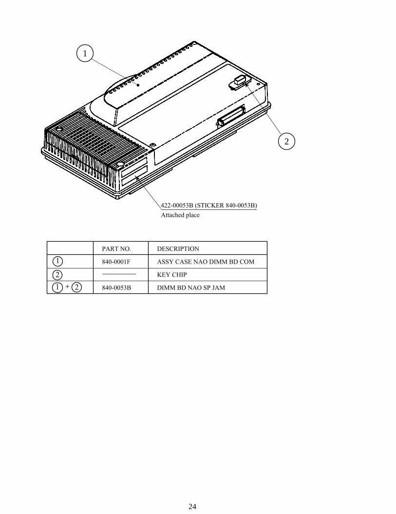
PART NO. DESCRIPTION
840-0001F ASSY CASE NAO DIMM BD COM
KEY CHIP
840-0053B DIMM BD NAO SP JAM
422-00053B (STICKER 840-0053B)
Attached place
1
2
1 2
1
2
+

25
Handling the GD-ROM Disk
Do not contaminate the disks with yourfingerprints or dust particles. Contaminateddisks may lower audio and video quality.When cleaning the disks, do not use volatilechemicals (benzine, thinner, etc.), cleaningsprays, and antistatic agents.Do not use cracked, warped, or damageddisks.Do not attach papers or seals onto the disks;do not scratch the disks.Do not use the disks with a sign of peeled seals, tapes, etc.Observing these instructions, do not insert such a non-usable diskinto the GD-ROM drive. Otherwise the inserted disk can not beejected.When cleaning a heavily contaminated disk, use clean cloth thathas been soaked in water and squeezed. Then remove moisturewith dry cloth.When holding a disk, be careful not to contaminate it with yourfingerprints.
How to Hold a Disk
With both hands:Put your thumbs and forefingers of bothhands on the disk's 4 circumference tips.
With one hand:Insert your forefinger into acentral hole and at the sametime put your thumb and middlefinger on the disk's 2circumference tips.
6. SOFT KIT
How to Handle the Key Chip
The key chip is a precision device. Handle it carefully because itmay be damaged by heat, shock, and static electricity.Use the key chip with the GD-ROM disk of the correspondinggame that has been shipped together with the key chip.
STOP
IMPORTANT
Use clean cloth to wipethe disk gently and into aradial direction.

26
PART NO. DESCRIPTION
610-0630-0003 GD SOFT KIT SP JAM ENG
GDS-0003 * NAOMI GDROM SP JAM
KEY CHIP
420-6621-0003E SERVICE MANUAL SP JAM ENG
253-5507 DISK CASE WITH IC HOLDER
1
2
3
4
1 2 3 4
1
2
3
4
+ ++

50
80
514150
50
31
838-13616
AUDIO POWER AMP 2CHJST VH 4P
TRANSFORMER 0V
120V 0V 17V
0V 17V
1
P C
WHI
TE(U
/P)
1
32
P C
560-5407
JST
VL
P C
JST
VL
+12V
GND
GND
GND
+3.3
V+5
V
GND
+3.3
V+5
V
GND
400-5397SW REGU FOR JVS
600-6743-050
600-7141-050
600-
7155
P C
838-
1368
3-91
3
21
30
10
50
50
120 Vac Input
[Extra]
5k pot
SPEAKER OUTPUTS
To PIN 8of Jamma
To ExtraYellow Wire
COIN COUNTER
JAMMA CONNECTIONS USED ARE:° VIDEO OUT° SWITCH INPUTS° SWITCH GROUND RETURNS° COIN COUNTER OUTPUT
NOTE: THERE ARE TO BE NOCONNECTIONS MADE TO THEJAMMA INTERFACE OTHER THANTHE ABOVE FOREMENTIONED.
1020304050
607080AB
CDE
NAOMI KIT UNIVERSALWIRING DIAGRAM (1/1)
CN6
Phonoplugs
71 91 72 92
10
30
50
50
3 42 5 6
30
10
50
30
10
50
61
[GD ROM DRIVE]
1 VCC
2 VCC
3 NC4 1P SW
65 1P SW
76 1P SW
87 NC8 2P SW
69 2P SW
710 2P SW
811 NC12 NC13 GND14 GND
JP1
MU
ST B
E SE
T T
O "IN
"T
O U
SE IN
PUT
S ON
CN
3
OUT
IN

VISIT OUR WEBSITE!