SEGA NAOMI Jamma Compatible Conversion...
14
SEGA ENTERPRISES, INC. USA 1ST PRINTING MARCH 99 MANUAL NO. 999-0784 TM SEGA NAOMI Jamma Compatible Conversion KIT
Transcript of SEGA NAOMI Jamma Compatible Conversion...

SEGA ENTERPRISES, INC. USA
1ST PRINTINGMARCH 99
MANUAL NO. 999-0784
TM
SEGA NAOMIJamma Compatible
Conversion KIT

Warranty
Your new Sega Product is covered for a period of 90 days from the date of shipment. This certifiesthat the Printed Circuit Boards, Power Supplies and Monitor are to be free of defects in workman-ship or materials under normal operating conditions. This also certifies that all Interactive ControlAssemblies are to be free from defects in workmanship and materials under normal operating condi-tions. No other product in this machine is hereby covered.
Sellers sole liability in the event a warranted part described above fails shall be, at its option, toreplace or repair the defective part during the warranty period. For Warranty claims, contact yourSega Distributor.
Should the Seller determine, by inspection that the product was caused by Accident, Misuse, Ne-glect, Alteration, Improper Repair, Installation or Testing, the warranty offered will be null and void.
Under no circumstances is the Seller responsible for any loss of profits, loss of use, or other dam-ages.
This shall be the exclusive written Warranty of the original purchaser expressed in lieu of all otherwarranties expressed or implied. Under no circumstance shall it extend beyond the period of timelisted above.

1
INSTALLATIONOF MACHINE
2. In the INPUT TEST mode, check each SW and VR.3. In the OUTPUT TEST mode, check each of lamps.4. In the MEMORY TEST mode, check ICs on the IC Board.
Choose MEMORY TEST in the MENU mode to allow theMEMORY test to be performed. In this test, PROGRAMRAMs, ROMs, and ICs on the IC Board are checked.
Periodically perform the following:1. MEMORY TEST2. Ascertain each setting.3. In the INPUT TEST mode, test the CONTROL device4. In the OUTPUT TEST mode, check each of lamps.
1. In the INPUT TEST mode, check each SW and VR.2. Adjust or replace each SW and VR.3. If the problem can not be solved yet, check the CONTROL’s moves.
In the MONITOR ADJUSTMENT mode, check to see if theMONITOR adjustment is appropriately made.
1. MEMORY TEST2. In the SOUND TEST mode, check the sound related ROMs.
Check such data as game play time and histogram to adjust thedifficulty level, etc
1. Check to see that each setting is as per standard setting made at the time of shipment.
MEMORY
MONITOR
DATA CHECK
CONTROLSYSTEM
When the machine is installed, perform the following:
IC BOARD
When performing installation, servicing product or changing game boards refer to individual kit instructionsfor each of the listed items below:
1 . EXPLANATION OF TEST AND DATA DISPLAY
ITEMS DESCRIPTION
In the case where plural machines are linked for communication play, if even one seat enters
the test mode, all of the linked seats will enter the test mode. Therefore, if any one of the
linked machines is in play, use care so as not to use the test mode.
The contents of the setting changes made will not be effective unless the test mode is
finished in the test mode. When the setting is changed, be sure to “EXIT” in the menu mode.
Do not press the TEST BUTTON during network check at the time of turning the power on or
exiting from the test mode. If anyone of the linked machines uses the test mode during
network check, all other Seats will continue network checking. Cause all of the Seats to
reenter the test mode and then have all of the Seats exit from the test mode simultaneously.
CAUTIONS TO BE HEEDED WHEN USING THE TEST MODE:
By operating the switch unit, periodically perform the tests and data check. When installing the machine initially orcollecting cash, or when the machine does not function correctly, perform checking in accordance with the explanationsgiven in this section. The following shows tests and modes that should be utilized as applicable.
PERIODICSERVICING

2
1 - 2 TEST MODESystem Menu. This test mode mainly allows the IC board to be checked for accurate functioning, monitor color to be
adjusted as well as COIN ASSIGNMENTS and GAME ASSIGNEMENTS to be adjusted.
The contents of settings changes in SYSTEM ASSIGNMENTS, COIN ASSIGNMENTS, and
GAME TEST MODE are stored when the test mode is EXITed. If the power is turned off
before EXITing, the contents of setting changes are ineffective. Be very careful of this
point.
3.) Bring the arrow to the item of Game TEST MODE and press the TEST button to display the GAME TEST MENU
peculiar to ZOMBIE REVENGE. See the next page onward.
4.) Upon finishing the test, bring the arrow to EXIT and press the TEST button to return to the Gam Mode.
1 - 3 GAME TEST MODE
Bring the arrow to the item of GAME TEST MODE in
the SYSTEM TEST MENU, and press the Test button to
display the TEST MENU peculiar to ZOMBIE RE-
VENGE.
Press the SERVICE button to move the arrow. Bring the
arrow the desired item and press the TEST button.
Upon finishing the test, bring the arrow to EXIT and
press the TEST button to return to the SYSTEM MENU
MODE.
SYSTEM MENUUSA VERSION
RAM TESTJVS TESTSOUND TESTSYSTEM ASSIGNMENTSCOIN ASSIGNMENTSBOOKKEEPINGBACKUP DATA CLEARCLOCK SETING
ROM BD TESTGAME TEST MODE(ZOMBIE REVENGE IN USA)
->EXITSELECT WITH SERVICE BUTTON
ANDPRESS TEST BUTTON
1.) After turning power on, press the TEST button to have the following test item menu displayed.
2.) Press the SERVICE button to move the arrow. Bring the arrow to the desired item and press the TEST button.
OPERATION REQUIREMENTS OF THIS GAME:In the SYSTEM ASSIGNMENTS,the CABINET TYPE is set to 2 PLAYER(s)and MONITOR TYPE is set to HORIZONTAL.
COIN ASSIGNMENTS intial settings<USA, EXPORT, AUSTRALIA Version>COIN CHUTE TYPE COMMONCOIN/ CREDIT SETTING #12
SEQUENCE SETTING OF COIN ASSIGNMENTSSEQUENCE 1: Number of credits required for Game Start. (intial value=1)SEQUENCE 2: Number of credits required for CONTINUE (intial value=1)SEQUENCE 3-8: NOT USED
MEANING OF DISPLAY IN BOOKEEPING (2/2)P1(P2) SEQ 1: Play frequency of Player 1 (Player 2)P1(P2) SEQ 2: Frequency of CONTINUE by Player 1 (Player 2)P1(P2) SEQ 3-8: NOT USED
(ZOMBIE REVENGE) TEST MENU
INPUT TESTSOUND TESTGAME ASSIGNMENTSSTICK SETTINGBOOKKEEPINGBACKUP DATA CLEAR
->EXITSELECT WITH SERVICE BUTTON
ANDPRESS TEST BUTTON

3
1 - 4 INPUT TEST
This test displays the state of each switch.
If this switch goes ON when activated, it is satisfactory.
Display varies depending on the JOYSTICK TYPE setting in (3) GAME ASSIGNMENTS.
1P (2P) UP-DOWN shows the minimum value when the Stick is inclined downward, and the maximum value when the
Stick is inclined upward.
1P (2P) LEFT-RIGHT sows the minimum value when the Stick is inclined to the right, and the maximum when the
Stick is inclined to the left. When the Stick is untouched, the CENTER value is displayed. If each of the center,
minimum, and maximum value is within range of 70-8F,00-0F, and F0-FF respectively, it is satisfactory.
If the value is not satisfactory, return to the MENU mode, make adjustment in (4) STICK SETTING, and reconfirm the
value in this test.
Press the test menu to have the MENU return onto the screen.
1 - 5 SOUND TEST
This allows sound and background used in the game to be checked/ tested.
Pressing the service button increase the number by one
and changes the sound.
Press the TEST button to have the MENU return to the
screen.
INPUT TEST
START1 :OFF START2 :OFFSW_SHOT 10 :OFF SW_SHOT 20 :OFFSW_SHOT 11 :OFF SW_SHOT 21 :OFFSW_SHOT 12 :OFF SW_SHOT 22 :OFF
TEST-SW :OFF SERVICE-SW :OFF1P UP - DOWN (VOLUME_0) :801P LEFT - RIGHT (VOLUME_1) :802P UP - DOWN (VOLUME_4) :802P LEFT - RIGHT (VOLUME_5) :80
PRESS TEST BUTTON TO EXIT
INPUT TEST
START1 :OFF START2 :OFFSW_SHOT 10 :OFF SW_SHOT 20 :OFFSW_SHOT 11 :OFF SW_SHOT 21 :OFFSW_SHOT 12 :OFF SW_SHOT 22 :OFF
SW_UP1 :OFF SW_UP2 :OFFSW_DOWN1 :OFF SW_DOWN2 :OFFSW_LEFT1 :OFF SW_LEFT2 :OFFSW_RIGHT1 :OFF SW_RIGHT2 :OFF
TEST-SW :OFF SERVICE-SW :OFF
PRESS TEST BUTTON TO EXIT
SOUND TEST
BGM : 00
SELECT WITH SERVICE BUTTONPRESS TEST BUTTON TO EXIT
4
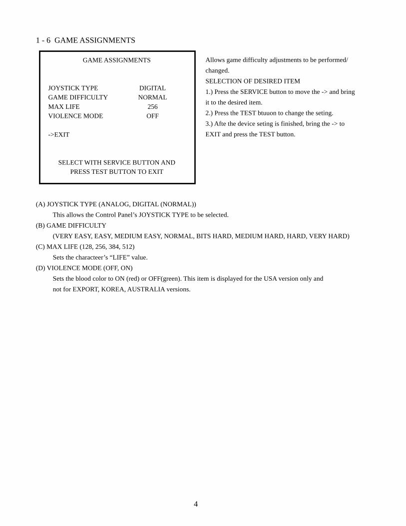
1 - 6 GAME ASSIGNMENTS
Allows game difficulty adjustments to be performed/
changed.
SELECTION OF DESIRED ITEM
1.) Press the SERVICE button to move the -> and bring
it to the desired item.
2.) Press the TEST btuuon to change the seting.
3.) Afte the device seting is finished, bring the -> to
EXIT and press the TEST button.
(A) JOYSTICK TYPE (ANALOG, DIGITAL (NORMAL))
This allows the Control Panel’s JOYSTICK TYPE to be selected.
(B) GAME DIFFICULTY
(VERY EASY, EASY, MEDIUM EASY, NORMAL, BITS HARD, MEDIUM HARD, HARD, VERY HARD)
(C) MAX LIFE (128, 256, 384, 512)
Sets the characteer’s “LIFE” value.
(D) VIOLENCE MODE (OFF, ON)
Sets the blood color to ON (red) or OFF(green). This item is displayed for the USA version only and
not for EXPORT, KOREA, AUSTRALIA versions.
GAME ASSIGNMENTS
JOYSTICK TYPE DIGITAL
GAME DIFFICULTY NORMAL
MAX LIFE 256VIOLENCE MODE OFF
->EXIT
SELECT WITH SERVICE BUTTON ANDPRESS TEST BUTTON TO EXIT

5
1 - 7 STICK SETTING
If the JOSTICK TYPE is set to DIGITAL in (3) GAME ASSIGNMENTS, the ANALOG STICK volume can be
adjusted.
ADJUSTING THE VOLUME VALUE
Starring from the untouched status of 1P (2P) DIGITAL STICK, adjust the Volume value by moving the Stick fully UP/
DOWN/LEFT/RIGHT within the maximum movable ranges.
There after, the adjustment is finished if the MENU mode returns when the TEST button is pressed in the status and
Stick is untouched.
After adjustment, be sure to check in (1) INPUT TEST to confirm that the value is satisfactory.
If the value is not staisfactory, return to STICK SETTING and adjust the Volume value. If the satisfactory value is not
obtained after adjusting several times, then, the STICK may be amlfunctioning.
In the case JOYSTICK TYPE is set to DIGITAL, the following is displayed.
Press the TEST button to have the MENU return to the screen.
NEW JAMMA ANALOG
MIN CENTER MAX1P UP - DOWN: 00 80 FF(VOLUME 0)
1P LEFT - RIGHT: 00 80 FF(VOLUME 1)
20 UP - DOWN: 00 80 FF(VOLUME 4)
20 LEFT - RIGHT: 00 80 FF(VOLUME 5 )
PRESS TEST BUTTON TO EXIT
NEW JAMMA DIGITAL
STICK TYPE IS SET DIGITAL!!
PRESS TEST BUTTON TO EXIT

6
1 - 8 BOOKKEEPINGThis test mode allows each of the CREDIT/TIME/GAME data to be ascertained.
(A) NUMBER OF GAMES 1P, 2P total game playfrequency.
(B) NUMBER OF CONTINUE
1P, 2P continue game playfrequency.(C) TOTAL COIN
Total number of times both the COIN CHUTE’S are actuated.
(D) COIN CREDIT Number of CREDITS registered by COIN insertion only.
(E) SERVICE CREDIT
The SERVICE SWITCH usage frequency.(F) TOTAL CREDIT
Total number of CREDITS.
(G) TOTAL TIME Machine’s total actuated time (excluding the test performance time).
(H) PLAY TIME
Displays total game play time.(I) AVERAGE TIME
Average Game play time.
(J) LONGEST TIME Displays the longest play time.
(K) SHORTEST TIME
Displays the shortest play time.
Press the test button to proceed to the next page.
Press the TEST button to have the MENU return to the screen.
BOOKKEEPINGGAME REPORT PAGE 1/2
NUMBER OF GAMES 0 1P GAMES 0 2P GAMES 0NUMBER OF CONTINUE 0 1P GAMES 0 2P GAMES 0
TOTAL COIN 0COIN CREDIT 0SERVICE CREDIT 0TOTAL CREDIT 0
TOTAL TIME 0D 0H 0M 0SPLAY TIME 0D 0H 0M 0SAVERAGE PLAY TIME 0D 0H 0M 0SLONGEST PLAY TIME 0D 0H 0M 0SSHORTEST PLAY TIME 0D 0H 0M 0S
PRESS TEST BUTTON TO EXIT

7
1 - 9 BACK UP DATA CLEARClears the contents of BOOKKEEPING.
When clearing bring-> to YES and when not clearing, to NO, by using the SERVICE SW and then push the TEST
button.
When clearing has been finished, COMPLETED will be dislayed.
Pressing the TEST button will have the MENU return to the screen.
BOOKKEEPINGTIME HISTOGRAM PAGE 2/2
0M00S ~ 0M29S 00M30S ~ 0M59S 01M00S ~ 1M29S 01M30S ~ 1M59S 02M00S ~ 2M29S 02M30S ~ 2M59S 04M00S ~ 4M29S 04M30S ~ 4M59S 05M00S ~ 5M29S 05M30S ~ 5M59S 06M00S ~ 6M29S 06M30S ~ 6M59S 07M00S ~ 7M29S 07M30S ~ 7M59S 08M00S ~ 8M29S 08M30S ~ 8M59S 09M00S ~ 9M29S 09M30S ~ 9M59S 0OVER
PRESS TEST BUTTON TO EXIT
BACK UP DATA CLEAR
YES (CLEAR)->NO (CANCEL)
SELECT WITH SERVICE BUTTON ANDPRESS TEST BUTTON TO EXIT
Page 2/2 displays by-play-time play frequency.

8
DIP SW SETTINGS
ASSY CASE NAO USA (840-0003D-01) : ZOMBIE USA
Ensure that the DIP SW setting is performed as designated. Failure to observe this
may cause functioning not suitable for the operation, or malfunctioning.
2. GAME BOARD
2 -1 COMPOSITION OF GAME BOARD

9
3. PARTS LIST
ITEM NO. PART NO. DESCRIPTION
1 999-0777 MARQUEE GRAPHIC ZBX KIT2 999-0779 INSTRUCTION SHEET ZBX KIT3 999-0780 SUB INSTR SHEET ZBX KIT4 999-0785 CNTRL PNL OVERLAY ZBX KIT5 999-0786 STICKER CABI SIDE L ZBX KIT6 999-0787 STICKER CABI SIDE R ZBX KIT
STICKERS AND GRAPHICS
JOYSTICKS AND BUTTONS
ITEM NO. PART NO. DESCRIPTION
1 610-6723-4C01 ASSY ANALOG JOY 4C GREEN2 58-9133-L *PUSH BUTTON GREEN3 58-9155-L *PUSH BUTTON YELLOW4 95-0733-01 *MICRO SWITCH SILVER CONTACT
KIT INSTALLATION INSTRUCTIONS
1.) Install VGA Output to Jamma Interface.
2.) Install USB connector to Naomi Filter Board Port.
3.) You can use one of the extra grounds (shown in the picture onthe following page) to go out to switched inputs. (The 5V and 12Vcan be used for whatever you like-coin meter, etc.)
MONITOR INFORMATION
You can use aStandard Resolution-15,750K x 60 (#1 ON & #2-4 OFF)
orHigh Resolution-31,000K x 10 (#1-4 OFF)
DIP SWITCH SELECTABLE(Switch #1 on NAOMI FILTER BOARD)

10
SPEAKER 1
SPEAKER 2
120 VAC in
VGA Outputto Jamma Interface
*12V Output (RED)
*Logic Ground (WHITE)
*5V Output (YELLOW)
3 2 1
5k pot(sound)
1=WHITE/RED
2=GREEN/RED
3=YELLOW/RED
*(USED FOR METER, COINDOOR, LIGHTS, ETC.)
GAME BD ZOMBIE NAO840-0003D-01
SW REGU FOR JVS400-5397
POWER AMP 2 CH838-13616
XFMR 120V 17v2Ax2560-5407
I/O Board838-13683
CONTENTS OF WIRING BAG SEEN ABOVE

Come see SEGA ENTERPRISES’ Service Department Homepage