NANOSTAR-UC3M Ground Base Station
35
1 NANOSTAR-UC3M Ground Base Station Antonio Carrera Maestro Universidad Carlos III de Madrid NANOSTAR consortium
Transcript of NANOSTAR-UC3M Ground Base Station

1
NANOSTAR-UC3M Ground Base Station Antonio Carrera Maestro
Universidad Carlos III de Madrid
NANOSTAR consortium

Project funded by the Interreg Sudoe Programme through the European Regional Development Fund (ERDF)
2

Project funded by the Interreg Sudoe Programme through the European Regional Development Fund (ERDF)
3
ABSTRACT
The main objective of this project is to design a basic ground station operating in the UHF band, which
is intended to receive signals from the nanosatellites in orbit.
The design has been divided into three blocks: antenna and receiving chain, radio and telemetry, and
pointing system. The first block receives the incoming signal and places it at an appropriate level and
frequency to carry out its ground processing. The second block carries out the demodulation and
decoding of the received signal. The third block predicts the future passes of the monitored satellites
and orientates the antenna in the desired direction to be able to establish a good communications
channel with the satellite.
The design consists of a Yagi-Uda antenna with a center frequency of 433 MHz, in conjunction with a
receiving chain consisting of a low-noise amplifier and a band-pass filter. The radio module is based
on a software defined radio. Observation predictions are performed by means of data collected from
online platforms, and the selected engine attached to the antenna has a software interface to be
controlled from the computer.
KEYWORDS: ground station, UHF, nanosatellites, antenna, radio, telemetry

Project funded by the Interreg Sudoe Programme through the European Regional Development Fund (ERDF)
4
ACKNOWLEDGMENTS
Many thanks to José Antonio García Souto for giving me the opportunity to work on this project and
for helping me during its development. I have been able to learn many new things and increase my
knowledge about nanosatellites.

Project funded by the Interreg Sudoe Programme through the European Regional Development Fund (ERDF)
5
TABLE OF CONTENTS
ABSTRACT ....................................................................................................................................3
LIST OF FIGURES ...........................................................................................................................6
APPLICABLE AND REFERENCE DOCUMENTS ..................................................................................7
INTRODUCTION AND MOTIVATION ............................................................................................ 11
STATE-OF-THE-ART ..................................................................................................................... 14
ANTENNA AND RECEIVING CHAIN .............................................................................................. 18
SIGNAL PROCESSING AND DECODING ......................................................................................... 26
TELEMETRY AND POINTING ........................................................................................................ 30
CONCLUSIONS AND FUTURE WORK ............................................................................................ 34

Project funded by the Interreg Sudoe Programme through the European Regional Development Fund (ERDF)
6
LIST OF FIGURES
Figure 1: Number of deposited patents related to cubesats [6] ......................................................... 12
Figure 2: Cubesat standardized sizes [11] ........................................................................................... 15
Figure 3: P-POD [15] ............................................................................................................................. 15
Figure 4: Example of a typical VHF-UHF ground station [13] .............................................................. 16
Figure 5: Schematic of a satnogs ground STATION [4] ........................................................................ 17
Figure 6: Yagi-Uda antenna [18] .......................................................................................................... 19
Figure 7: Radiaton pattern and SWR for the first antenna (without optimization) ............................ 20
Figure 8: Radiation pattern and SWR for the first antenna (with optimization) ................................. 20
Figure 9: Radiaton pattern and SWR for the second antenna (without optimization) ....................... 21
Figure 10: Radiation pattern and SWR for the second antenna (with optimization) .......................... 21
Figure 11: Antenna 3D printed parts [24] ............................................................................................ 24
Figure 12: LNA and bandpass filter [20][21] ........................................................................................ 25
Figure 13: SDR block diagram [27] ....................................................................................................... 26
Figure 14: RTL2832U [30] ..................................................................................................................... 27
Figure 15: GMSK decoding ................................................................................................................... 28
Figure 16: Pre-processing block ........................................................................................................... 28
Figure 17: AO-40 decoder [36] ............................................................................................................. 29
Figure 18: Geographical antenna location in Leganés [37] ................................................................. 30
Figure 19: SMOG-P pass predictions for selectedd location [38] ........................................................ 31
Figure 20: TLE for the ISS at a certain time [41] .................................................................................. 31
Figure 21: TLE-based pass predictions for SMOG-P [42] ..................................................................... 32
Figure 22: Yaesu 5500-g control interface [43] ................................................................................... 33

Project funded by the Interreg Sudoe Programme through the European Regional Development Fund (ERDF)
7
APPLICABLE AND REFERENCE DOCUMENTS
Bibliography:
[1] M.G. DIONIS. "Jordi Puig-Suari, ingeniero aeroespacial: "Hemos democratizado el espacio con
los nanosatélites"". Sinc. URL: https://www.agenciasinc.es/Entrevistas/Hemosdemocratizado-el-
espacio-con-los-nanosatelites. (access: March 15th, 2020)
[2] D. KIM. "The "Democratization of Space" and the Increasing Effects of Commercial Satellite
Imagery on Foreign Policy". CSIS. URL: https://www.csis.org/democratization-spaceand-increasing-
effects-commercial-satellite-imagery-foreign-policy. (access: March 15th, 2020).
[3] W. WELSER. "The Democratization of Space". The RAND Blog. URL:
https://www.rand.org/blog/2016/03/the-democratization-of-space.html. (access: March 16th,
2020)
[4] Anonymous. "SatNOGS Wiki". SatNOGS. URL: https://wiki.satnogs.org/Main_Page. (access:
March 24th, 2020)
[6] E. KULU. "Nanosatellite & CubeSat Database". Nanosats database. URL:
https://www.nanosats.eu/database. (access: June 6th, 2020)
[7] T. VILLELA, C. COSTA, A. BRANDAO, F. BUENO y R, LEONARDI. "Towards the thousandth CubeSat:
A statistical overview," International Journal of Aerospace Engineering, p 1-13, 2019.
[8] M. J. FUENTE, "La Universidade de Vigo sumará ya siete satélites puestos en órbita el próximo
año". La voz de Galicia. URL:
https://www.lavozdegalicia.es/noticia/sociedad/2018/11/30/universidade-vigo-sumara-
sietesatelites-puestos-orbita-proximo-ano/0003_201811G30P28992.htm. (access: June 20th, 2020)
[9] Anonymous. Guía básica de nanosatélites. Alén Space. URL: https://alen.space/es/guiabasica-
nanosatelites/. (access: March 20th, 2020)
[10] Anonymous. "CubeSat". Wikipedia. URL: https://en.wikipedia.org/wiki/CubeSat. (access:
March 14th, 2020).
[11] E. MABROUK. "What are SmallSats and CubeSats?". NASA. URL:
https://www.nasa.gov/content/what-are-smallsats-and-cubesats (access: March 26th, 2020)
[12] J. CHIN et al, "CubeSat 101: Basic Concepts and Processes for First-Time CubeSat Developers".
NASA CubeSat Launch Initiative. 2017. [Online]. Available at:
https://www.nasa.gov/sites/default/files/atoms/files/nasa_csli_cubesat_101_508.pdf
[13] C. NIETO-PEROY y R. EMAMI, "CubeSat Mission: From Design to Operation,", Applied Sciences.
2019.
[14] S. e. a. LEE, CubeSat Design Specification REV13. February 20th, 2014.

Project funded by the Interreg Sudoe Programme through the European Regional Development Fund (ERDF)
8
[15] R. NUGENT, R. MUNAKATA, A. CHIN, R. COELHO, J. PUIG-SUARI. "The CubeSat: The Picosatellite
Standard for Research and Education," en AIAA Space 2008 Conference & Exposition, 2008.
[16] R. MARTINEZ y S. COCA, "Diseño preliminar de una estación terrena basada en software radio
para aplicaciones docentes," 2008.
[17] P. MURI, C. OBULPATHI y J. MCNAIR, "Enhancing small satellite communication through
effective antenna design," in 2010-MILCOM 2010 MILITARY COMMUNICATIONS CONFERENCE, pp.
347-352, 2010 pp. 347-352.
[18] M. DERKS et al, "Design and construction of a Yagi-Uda antenna for the 433 MHz band,"
University of Twente.
[19] L. RUPESH et al, "Design and Performance Evaluation of Two-Unit YAGI-UDA Array for UHF
Satellite Communication", International Journal of Wireless & Mobile Networks (IJWMN), vol. 6, nº.
5, oct. 2014.
[20] Anonymous. "Amplifiers". Minicircuits. URL:
https://www.minicircuits.com/WebStore/Amplifiers.html. (access: April 16th, 2020)
[21] Anonymous. "RF Bandpass Filters". Minicircuits. URL:
https://www.minicircuits.com/products/RF-Bandpass-Filters.html. (access: April 19th, 2020)
[22] Anonymous. "Varilla de aluminio RS Pro, 5mm x 1m". RS.URL:
https://es.rsonline.com/web/p/varillas-y-barras-de-aluminio/1368731/. (access: April 27th, 2020)
[23] Anonymous. "Tubo Cuadrado 15x15x2000 aluminio". Mastil-Boom .URL:
https://mastilboom.es/es/cuadrado-15mm/125-tubo-cuadrado-15x15x2000-aluminio.html.
(access: April 27th, 2020)
[24] P. PAPADEAS. "453MHz-10EL8mm-2m-50-Ohm-Yagi-3D". GitLab.URL:
https://gitlab.com/librespacefoundation/satnogs/satnogs-antennas/-/blob/master/Yagi/YagiUHF-
v1/435MHz-10EL8mm-2m-50-Ohm-Yagi-3D.pdf. (access: April 28th, 2020).
[25] Anonymous. "Schwarzbeck UHA 9105 Half-Wave Tuned Dipole Antenna". The EMC Shop. URL:
https://www.theemcshop.com/schwarzbeck-dipole-antennas/2735-schwarzbeck-uha9105-half-
wave-tuned-dipole-antenna.html. (access: April 21st, 2020)
[26] Anonymous. "Software Defined Radio". Sdr-radio.com URL: https://www.sdr-radio.com/.
(access: April 27th, 2020).
[27] R. AKEELA y B. DEZFOULI, "Software-Defined Radios: Architecture, State-of-the-art and
Challenges", Computer Communications, vol. 128, pp 106-125, mar. 2018.
[28] Anonymous. "SMOG - 1". BME-GND. URL: http://gnd.bme.hu/smog#satelite. (May 5th, 2020).
[29] A. AGUDELO, P. C. BERNAL y E. A. QUINTERO, "Modulación GMSK para Transmisión de
Información a través de Líneas Eléctricas", Scientia et Technica, vol. 46, pp. 86- 90, dic. 2010.

Project funded by the Interreg Sudoe Programme through the European Regional Development Fund (ERDF)
9
[30] RTL-SDR "RTL-SDR Blog V3 Datasheet".
[31] A. LØFALDLI y R. BIRKELAND, "Implementation of a sofware defined radio prototype ground
station for CubeSats," at ESA Small Satellites Systems and Servides Symposium, jun. 2016.
[32] D. LEVENTE, "SMOG-P and ATL-1 reception," Departamento de Infocomunicaciones de Banda
Ancha y Teoría Electromagnética, Universidad de Tecnología y Economía de Budapest, Hungría,
ene. 2020. D. LEVENTE, "SMOG-P and ATL-1 reception," Jan 3, 2020.
[33] M. MWAKYANJALA, R. EMAMI and J. BEEK, "Software-defined radio transceiver for QB50
CubeSat telemetry and telecommand," at 34th AIAA International Communications Satellite
Systems Conference, oct. 2016.
[34] E. SRT TEAM, "Student Report - NANOSTAR," unpublished, private communication, 2019.
[35] K. D. VEA, "NUTS: Ground Station with GNU Radio and USRP.", Electronic and
Telecommunications Department, Norwegian University of Science and Technology, jun. 2015.
Available at:
https://ntnuopen.ntnu.no/ntnuxmlui/bitstream/handle/11250/2371557/13825_FULLTEXT.pdf?seq
uence=1&isAllowed=y
[36] D. ESTEVEZ. "Soft Viterbi decoder for AO-40 FEC". Daniel Estévez. URL:
https://destevez.net/2018/03/soft-viterbi-decoder-for-ao-40-fec/. (access: May 21st, 2020)
[37] Anónimo. "Juan Benet Building". Google Maps. URL:
https://www.google.com/maps?q=edificio+juan+benet+uc3m&gs_lcp=CgZwc3ktYWIQAzIGC
AAQFhAeOgQIABBDOgcIABCxAxBDOgIIADoFCAAQsQM6BQghEKABUMMLWMlDY
LtGaAdwAHgBgAHWAogB6iaSAQgyLjEyLjguM5gBAKABAaoBB2d3cy13aXo&uact=5&u
m=1&ie=UTF8&sa=X&ved=2ahUKEwj3w5_ZubHqAhVV5uAKHUPFBSgQ_AUoAXoECBEQAw. (access:
June 1st, 2020).
[38] Anónimo. "Live Real Time Satellite Tracking and Predictions". n2yo. URL:
https://www.n2yo.com/. (access: June 6th, 2020).
[39] D. FORD. "Live World Map of Satellite Positions". in-the-sky. URL: https://in-
thesky.org/satmap_radar.php?year=2020&month=7&day=3. (access: June 8th, 2020)
[40] T.S. KELSO. "NORAD Two-Line Element Set Format". Celestrak, URL:
https://www.celestrak.com/NORAD/documentation/tle-fmt.php. (access: June 8th, 2020).
[41] Anonymous. "Two-line element set". Wikipedia. URL:
https://en.wikipedia.org/wiki/Twoline_element_set. (access: June 9th, 2020).
[42] J.T. SATRE. "Satellite tracker based on two line elements". satellite-calculations URL:
https://www.satellite-calculations.com/TLETracker/SatTracker.htm. (access: June 9th, 2020)
[43] Yaesu, "G-5500 Instructor Manual," 2015.

Project funded by the Interreg Sudoe Programme through the European Regional Development Fund (ERDF)
10
[44] Anonymous. "SatNOGS Rotator v3". SatNOGS. URL:
https://wiki.satnogs.org/SatNOGS_Rotator_v3. (access: June 15th, 2020).
[45] Yaesu, "GS-232 A Computer Control Interface for Antenna Rotators," 2000.

Project funded by the Interreg Sudoe Programme through the European Regional Development Fund (ERDF)
11
INTRODUCTION AND MOTIVATION
The main target of this project is the design of a simple ground station to be located at UC3M, in
Leganés. The aim is to receive signals from nanosatellites in orbit and extract the information they
contain. There are already two NANOSTAR ground stations in different stages of development (ISAE-
Toulouse and Bourdeaux-INP), to which the UC3M ground station will be added. This fact offers the
possibility of creating a terrestrial network that will allow the satellites to be jointly monitored.
The final goal can be split into three independent processes, which can be set as checkpoints for the
project. These three sub-objectives are:
• Design of an UHF antenna and its receiving chain, to allow filtering and amplification of the
signal for further ground processing.
• Implementation of the software that allows the communication between the ground station
and the satellite, and signal processing to obtain the incoming information from the satellite.
• Satellite pass prediction and trajectory tracking capabilities.
The resources used in the project can be classified under the following groups: software tools,
NANOSTAR shared resources and workplace. The software tools used in each of the project blocks
are the following:
• Antenna and receiving chain design. The design and optimization of the antenna has been
carried out by means of the 4nec2 software. This is a free software that allows modeling
antennas and optimizing their performance according to their characteristic parameters.
Initially, the MATLAB Antenna Toolbox extension was also used to simulate the behaviour of
the antenna, but 4nec2 was finally selected.
• Software Defined Radio (SDR). The tool used to design the SDR configuration is GNURadio
Companion. This program is open source and allows the different components of the
designed radio to be defined in a block diagram. Similarly, the program files can be coded
using Python.
• Satellite pass prediction and trajectory tracking. In this section the information has been
obtained from different web sites. The n2yo and Celestrak platforms have been the main tools
for obtaining real-time satellite positioning data and predicting future passages. This
information has been completed by making use of other platforms such as in-the-sky.org.
The nanosats.eu database has been used as a reference for various matters in all sections. It contains
a wide variety of nanosatellites, on which filters can be applied to select certain satellites according
to specific parameters. For example, it has been used to obtain the nanosatellites operating in the
UHF band.
The workplace has been the Laboratory of the Sensors and Instrumentation Techniques Research
Group of the Department of Electronic Technology, located at the Polytechnic School of the UC3M in
Leganés.

Project funded by the Interreg Sudoe Programme through the European Regional Development Fund (ERDF)
12
One of the key factors in the irruption of CubeSats in the space industry is the remarkable reduction
of the design and implementation costs in comparison with a conventional satellite. This fact allows
new institutions such as UC3M to participate in space projects. The price of a CubeSat is around
50,000 dollars, while the price of a conventional satellite is several million dollars, even hundreds [1].
In this context, it is possible to "democratize space", involving new different institutions in this type
of projects and providing access to space to organizations with fewer resources than state agencies.
This is one of the reasons why investment in this type of satellite is increasing.
The democratization of space is a concept that is linked to the development of nanosatellites.
Technological advances and increased accessibility to launch systems have changed the status quo in
the aerospace industry [2]. Market barriers have been lowered, leading to the emergence of new
stakeholders [3]. This has led to academic institutions such as universities being able to develop their
own prototypes. The growth in the number of participants in the sector requires a new economic
model that is more flexible, so that it can adapt more easily to the arrival of new participants.
One of the main characteristics of this new philosophy is the wide availability of information. In the
previous era, information was rarely shared, and each government agency developed its own
prototypes. Today, there are many open-source platforms where documentation is available for
researchers. An example of such a platform is SatNOGS, which seeks to build a network of ground
stations around the world based on modular components [4]. To this purpose, a common software
has been developed for the stations and there is a database in which it is possible to find the
guidelines to build the different parts of the ground station.
In terms of statistics, in April 2020, a total of 1317 nanosatellites had been launched into space,
coming from 66 different countries [5]. The number of CubeSats launched into space has grown with
an exponential tendency over the years and is expected to continue [6]. The reliability of the missions
has also increased over the years, reaching around 75%, which makes the investment more feasible,
since the first years there was a much higher failure rate. The number of patents related to CubeSats
has grown over the years, reaching the number of 304 in 2017.
FIGURE 1.- NUMBER OF DEPOSITED PATENTS RELATED TO CUBESATS [6]

Project funded by the Interreg Sudoe Programme through the European Regional Development Fund (ERDF)
13
In Spain, a high number of nanosatellite projects have already been carried out with great relevance,
both at the academic and professional aspects. Among the academic projects is the one of the
University of Vigo. This project planned to send seven satellites into space by 2019 [7]. The
organization was conducted in conjunction with Alén Space and the Galician Center for Space
Innovation. Just as the University of Vigo stands out in the academic field, Alén Space is one of the
leading Spanish private companies, which offers solutions in the field of nanosatellites. This company,
based in Galicia, has a previous experience of 12 years in the nanosatellite industry and has a 100%
success rate in the missions which have been carried out [8].

Project funded by the Interreg Sudoe Programme through the European Regional Development Fund (ERDF)
14
STATE-OF-THE-ART
The space race began in the mid-20th century with the launch of the first-ever satellite in 1957 as
part of the Soviet Union's Sputnik mission. Since then, numerous countries and organizations have
continued to send satellites into space [9]. These satellites have been characterized mainly by their
large size, long development time and high cost. Therefore, the launch of these satellites has been
the exclusive competence of governmental and highly funded institutions, such as NASA or ESA.
The emergence of nanosatellites has meant a major change in space missions, mainly in terms of
economics, development time and size [9]. These changes allow many more launch initiatives to
emerge, encouraging the rise of organizations with lower budgets. In this way, research centers and
universities can carry out their own projects, both for exploration and research purposes, as well as
for educational purposes [10]. It should be noted that the reliability of this type of missions is much
lower than in the case of conventional satellites, as there are not the same resources or the same
number of people involved in the missions.
Nanosatellites are a type of satellite characterized by a weight between 1kg and 10kg [11]. This allows
their development time to be greatly reduced in comparison to conventional satellites, with missions
lasting between 5 and 15 years to missions lasting less than one year [9]. The reduction in mission
time and budget implies exposure to a higher risk of failure and a much shorter average lifetime than
conventional satellites.
Launching such satellites is another key point for the low economic cost of the missions. Generally,
the satellite is transported to the appropriate altitude by larger space vehicles, which are responsible
for placing it in the corresponding orbit [12]. The most commonly used orbit type is the Low Earth
Orbit or LEO, in which the satellite orbits at an altitude of about 500km above the Earth's surface
[10]. The used orbits are generally polar orbits, in which the satellite follows the position defined by
the meridians.
The standardization of technologies is also key for the growth in this sector. In this aspect, the
CubeSat standard is the most significant standard. The CubeSat idea was first formulated at the end
of the last century, between 1998 and 1999, at the universities of Stanford and California State
Polytechnic in the USA [10]. The first ever CubeSat was sent into space in 2003.
The CubeSat standard belongs to the group of SmallSats, which are satellites characterized by a
weight of less than 180 kg [11]. Therefore, within the previously defined group, a CubeSat must
satisfy a set of restrictions in terms of shape, weight and size. There are several possible sizes, which
are based on the aggregation of fundamental units, defined as "1U". The fundamental unit is defined
as a cube with a side of 10 cm and a mass between 1 kg and 1.33 kg. From here, it is possible to
develop satellites of a larger size, including 1.5U, 2U, 3U and 6U, as it can be seen in Figure 2.

Project funded by the Interreg Sudoe Programme through the European Regional Development Fund (ERDF)
15
FIGURE 2.- CUBESAT STANDARDIZED SIZES [11]
The defined standard also provides for a standardization of the development process. The
specification defines requirements that the satellite must satisfy to comply with the standard, which
include general, mechanical, electrical and operational requirements [13]. It also defines a set of tests
that the prototype must undergo in order to guarantee its safety. When all the tests have been
successfully completed, launch may be authorized.
An essential device for launching CubeSats is the P-POD or Poly-Picosatellite Orbital Deployer, which
has been standardized in the same way as the CubeSat. This component was created in 1999 by the
developers of the CubeSat standard [14]. The main objective was to establish a certain consistency
in the design and launch missions of this type of satellites. The P-POD is an aluminum container
capable of ejecting its payload, consisting of a maximum of 3 CubeSats. This makes it possible to
combine the launch of multiple satellites in a single trip, which reduces the individual launch cost.
Apart from the previously mentioned functionalities, it also serves as a satellite protection
mechanism and a launch mechanism [15]. Therefore, it has become one of the standard interfaces
employed in this type of space missions. An image of the P-POD is shown in Figure 3.
FIGURE 3: P-POD [15]

Project funded by the Interreg Sudoe Programme through the European Regional Development Fund (ERDF)
16
Finally, the most important part for this project is the ground station. The ground station is the
remaining key element in the existing communication channel with the satellite. After launch, it
allows the satellite's position to be tracked and the communications with the satellite to be carried
out. It consists mainly of an antenna and a radio. In some cases, the antenna may be accompanied
by a pointing system [16]. The design of the ground station must be parallel to the satellite
development, as it is a critical element for the accomplishment of the mission. For this reason, it is
important to carry out a very strict test prior to launch, because if it fails, the ability to communicate
with the satellite will be lost [12].
The ground station should operate in different frequency bands, usually VHF and UHF, to which the
S-band may be added. The antenna needs to be located in a clear place with a wide range of vision,
such as a rooftop. It should also have mechanisms that allow high receiving gain, as satellites transmit
at low power levels. To achieve this, the use of directional and orientable antennas and low noise
amplifiers is suggested [13]. The radio will be responsible for the demodulation of the received signal.
Generally, the use of amateur radio components is feasible [12].
There are many possibilities when it comes to defining the ground station architecture [16].
Traditional designs have a more inflexible design, consisting of commercial off-the-shelf components
put together. These components are the antenna, positioner, transceiver and modem. Ground
stations based on a software radio are generally more flexible, as they allow for signal processing
that is more adapted to the characteristics required by the user's needs. Figure 4 shows a typical
example of a ground station.
FIGURE 4.- EXAMPLE OF A TYPICAL VHF-UHF GROUND STATION [13]
Currently, there are terrestrial networks of ground stations such as the SatNOGS platform. This
project aims to build a global network of ground stations, through collaboration between
participants, who have web access to the telemetry received by each ground station in the network

Project funded by the Interreg Sudoe Programme through the European Regional Development Fund (ERDF)
17
[4]. There is a large amount of open-source material, accessible to any user. The stations in this
network are based on a SDR or Software Defined Radio and a Raspberry Pi. In this way, any user can
start building their own ground station and become a member of the network. Likewise, the platform
has a wiki in which the relevant guidelines are given to proceed with the development of each of the
stages of the project. The schematic of this kind of ground stations can be observed at Figure 5.
FIGURE 5: SCHEMATIC OF A SATNOGS GROUND STATION [4]
The objective of this project will be to design a basic ground station, which complies with the
mentioned flexible design criteria.

Project funded by the Interreg Sudoe Programme through the European Regional Development Fund (ERDF)
18
ANTENNA AND RECEIVING CHAIN
The first phase of development consists in designing an antenna to receive the signals from the
monitored satellites. This antenna will be accompanied by a circuit that will adapt the received signal
to the required levels so that it can be processed on the ground. In this way, at the output of the
circuit, the signal will be ready for ground processing in the following stages.
The objective is to receive signals from nanosatellites and CubeSats. This fact leads to consider
several aspects when selecting the type of antenna and receiving circuit. The most important aspects
are the following [5], [9], [17]:
• Low transmitting power and low transmitting efficiency. The typical power used in a
nanosatellite is 0dBW. Considering the attenuation due to propagation and reflections on
atmospheric elements, the expected signal level at the earth's surface is very low. Therefore,
the antenna must have a sufficiently high gain to receive the signal correctly. The typical
received signal level is -120dBW. The low efficiency of the antennas is also a factor to be
considered since the used antennas are generally deployable to remain protected during
periods of inactivity [17].
• Frequency band. Typically, CubeSats in the UHF band transmit at frequencies around 437
MHz. An alternative to this frequency would be 915 MHz. The 437 MHz band is defined as an
amateur satellite service band.
• LEO orbits. Nanosatellites and CubeSats are situated in LEO orbits with altitudes between
200km and 1000km. This is because of the low budget used in this type of project, and it
means that low transmission power is employed and the cost of putting the satellite into orbit
is lower than in other orbits. The implication of this type of orbit is that it requires a steerable
antenna. The satellite moves with a high relative velocity with respect to the Earth, so it is
essential to follow its trajectory, because in an omnidirectional station, signals of greater
magnitude would be received, and this fact would affect the correct reception of the signals.
• Polarization of the received signal. The low cost of this type of mission sometimes makes it
necessary to use very simple antennas with linear polarization, such as the λ/2 dipole. The
objective is to build a ground station that is capable of receiving as many different signals as
possible. It should be noted that apart from linear polarization, there are other types of
CubeSats that use circular polarization. Another important factor is the influence of the
transmission medium, in this case the atmosphere, which can affect the type of wave
polarization, leading to the reception of elliptically polarized waves in some cases.
Two antennas that could satisfy the above requirements have been selected: the Yagi-Uda antenna
and the helical antenna. The main difference between these two antennas is the polarization. The
Yagi-Uda antenna offers more flexibility in terms of polarization, whereas the helical antenna is
specially designed for circular polarizations. Therefore, the Yagi-Uda model has been chosen because
of the greater number of possibilities it offers and the greater ease of construction. Apart from these
advantages, it also offers benefits when it comes to orientation, as it has a simple structure that
allows it to be easily moved. Figure 6 shows the selected antenna.

Project funded by the Interreg Sudoe Programme through the European Regional Development Fund (ERDF)
19
FIGURE 6: YAGI-UDA ANTENNA [18]
Yagi-Uda antennas are defined by mathematical equations of high complexity. There are some
designs that try to simplify the parameters and use a fixed structure, but in this case the choice is to
find already designed models that can match the given specifications. The first alternative found are
tables of values, which contain the ideal lengths for a given number of reflectors and directors. The
second alternative evaluated are the models found in academic articles, which have already been
successfully tested in the past. Then, to ensure the correct antenna performance based on previous
successful cases, two antenna models operating at 433 MHz and 437 MHz have been selected. As the
type of antenna is the same in both cases, this gives the possibility to have another model available
in case the built antenna does not behave as expected.
Once the search has been completed, the 4nec2 software is used to simulate the ideal behaviour of
the antenna in the selected frequency range. In addition to simulation, the program offers a wide
range of possibilities to optimize the input parameters. There is a functionality which, by means of
the method of moments, allows for the optimization of the dimensions. The main parameter to be
enhanced is the standing wave ratio or SWR, so that the matching network is simplified as much as
possible.
Model 1: 11-element Yagi-Uda with center frequency at 433 MHz
The first model was extracted from a paper published by students from the University of Twente [18].
It is a Yagi-Uda antenna with parameters designed through numerical solutions calculated by
software. This design has an input impedance of 75 ohms and a length of less than 2 meters. The
obtained dimensions are shown in the document.
The design values of the antenna are calculated for an input impedance of 75 ohms, but in the project
the desired input impedance is 50 ohms. The behaviour of the antenna is then simulated with the
initial design for the desired 50 ohms, to extract conclusions about the general performance of the

Project funded by the Interreg Sudoe Programme through the European Regional Development Fund (ERDF)
20
antenna. Once it has been verified that the model could achieve the desired specifications, it is then
optimized. The bandwidth should be approximately 10MHz, with a gain of around 15dB. The SWR
should be close to one over the whole band.
First of all, the behaviour of the predefined values in the radiation pattern and the SWR (Standing
Wave Ratio) plots are analysed. The results are shown in Figure 7.
FIGURE 7: RADIATON PATTERN AND SWR FOR THE FIRST ANTENNA (WITHOUT OPTIMIZATION)
The SWR takes a value close to 2 in the selected band, which is then optimized for an impedance of
50 ohms and the centre frequency of 433 MHz. Figure 8 shows that, after optimization, an SWR
close to one is obtained once the dimensions have been modified, so the result is satisfactory. The
impedance of the antenna is almost 50 ohms. The only parameter that could be improved is the
gain, which is 12dB. For this purpose, an alternative model is simulated.
FIGURE 8: RADIATION PATTERN AND SWR FOR THE FIRST ANTENNA (WITH OPTIMIZATION)

Project funded by the Interreg Sudoe Programme through the European Regional Development Fund (ERDF)
21
Model 2: 13-element Cross-Yagi with center frequency at 437 MHz
This model has been developed by the Pune College of Engineering [19] in India. In this case, it is a
Cross-Yagi antenna that is designed for the same purpose of this project, as it is intended for
CubeSats.
The chosen antenna has a center frequency of 437.025 MHz, so it is well suited to the defined
conditions. The used dipole has a length of λ/2, and the reflector and director lengths are included
in a table. Then, we proceed in the same way as in the previous case. Initially, the given values are
simulated as a baseline, and then the optimization is performed. Figure 9 shows the result obtained
for the simulation without optimization.
FIGURE 9: RADIATION PATTERN AND SWR FOR THE SECOND ANTENNA (WITHOUT OPTIMIZATION)
This radiation pattern clearly shows the difference with the first model. The higher number of
directors results in an increased gain in the maximum direction, which is close to the desired 15dB.
Also, the side lobes are less prominent. The SWR increases considerably with respect to the previous
example, reaching a value of 3.38 at the center frequency of the antenna. These facts justify the need
to optimize the parameters.
FIGURE 10: RADIATION PATTERN AND SWR FOR THE SECOND ANTENNA (WITH OPTIMIZATION)

Project funded by the Interreg Sudoe Programme through the European Regional Development Fund (ERDF)
22
It can be seen from the diagram that optimization based on SWR improvement affects the gain, which
decreases slightly. It can also be seen that the side lobes are a little more pronounced than in the
previous simulation. The SWR is clearly reduced, taking a value of 1.07 at the center frequency of the
antenna. The conclusion is that the optimization provides a more adequate result for the project's
objectives, but in contrast, the gain of the antenna is sensibly reduced. Even so, the result is still
positive, as the gain has been improved with respect to the previous model, and a more uniform SWR
is achieved throughout the band. The main disadvantage of this model compared to the previous one
is that it is larger in length than the previous antenna and more complex in terms of assembly.
The next step is to design the receiving chain, which can be approached in different ways. In this case
we will choose a simple design. In this case, a preamplifier with a low noise figure will be used to
recover the signal and avoid distortion as much as possible. Afterwards, a filter will be used to select
the appropriate band, which complements the selection made by the antenna itself, due to its
reduced bandwidth. Finally, the use of a final amplifier will be considered if required.
For the selection of the LNA, a comparison of different possibilities has been made, allowing different
scenarios to be evaluated according to the required characteristics. Therefore, the amplifiers have
been classified according to their gain and the characteristic noise factor of each one, looking for a
balance between both parameters. The platform consulted to determine these amplifiers and
evaluate their characteristics is the Minicircuits website [20]. The following table shows the studied
amplifiers.
TABLE 1: STUDIED LNA [20]
Name Gain NF (Noise Factor) Band (MHz) Price
ZRL-700+ 30dB 2dB 250 – 700 $119,95
ZX60-33LNR-S+ 14,1dB 1,1dB 50 - 3000 $99,95
ZX60-3018G-S+ 20dB 2,7dB 20 - 3000 $79,95
ZX60-P103LN+ 13dB 0,6dB 50 - 3000 $69,95
The amplifiers shown in Table 2 all have the common characteristic that their impedance is equal to
50Ω and they have an SMA connector, suitable for working with radio frequency. After making the
comparison and evaluating the requirements to be covered in this first receiving stage, the amplifiers
with the smallest noise figure were chosen. Therefore, the ZX60-33LNR-S+ and ZX60-P103LN+ models
have been chosen, in this order of preference. The distinction between both amplifiers is that the
first one is intended for front-end use, while the second one has a more general purpose.
Bandpass filters are also important in this type of systems, as they allow the selection of the band to
work with for easier ground processing. The filter will be placed after the LNA in the receiving chain.

Project funded by the Interreg Sudoe Programme through the European Regional Development Fund (ERDF)
23
As with the LNAs, the Minicircuits website [21] has been used as a source of information. Table 2
shows the pre-selection of bandpass filters:
TABLE 2: BANDPASS FITERS
Name Band (MHz) Impedance (Ω) Price ($)
RBP-440+ 410 – 470 50 13,70
BPF-C450+ 400 – 510 50 31,95
SXBP-425+ 410 – 440 50 17,95
The selected filter is the RBP-440+, as it is the one with the closest frequency to the 433-437 MHz
band. This means that the return loss associated with the frequencies in the selected band reaches
the lowest filter values in that area, at around 1.43dB, with an SWR of 1.17. The phase deviation is
also very close to zero in that band. If it is proved that the selected filter is not suitable for the project,
the next option to consider would be the BPF-C450+ filter.
The interconnection wire to be used will be 50Ω coaxial cable, so that losses are minimized as far as
possible. Among the possible models considered, the RS Pro RG58 coaxial cable is the chosen one,
which is affordable in price, but requires an adapter to convert from SMA to BNC connection.
Therefore, it is possible to use connectors to switch from one output port to the other, but it should
be noted that the BNC connector is generally used for lower frequency applications. This leads to the
possibility of using SMA patch cables to interconnect microwave components such as the LNA or the
bandpass filter.
Practical implementation
The chosen antenna prototype for the station is the first model, due to its lower complexity of
assembly. Table 3 shows the dimensions obtained for the different components of the antenna,
which provide the basis for its subsequent installation.
TABLE 3: ANTENNA DIMENSIONS
Element Length (mm) Position (mm)
Reflector 343,2 -138
Dipole 328 0
Director 311,6 51,8
Director 304,6 176,1
Director 301 342,6
Director 298,4 497,3

Project funded by the Interreg Sudoe Programme through the European Regional Development Fund (ERDF)
24
Director 297,2 690,7
Director 289 897,9
Director 210 1155,5
Director 287,4 1343,5
Director 284,6 1581,8
The length defines the dimensions of each element and the position determines the location of the
components on the antenna mast, with the dipole being the coordinate reference.
To build the directors and reflectors, a 5mm diameter, 1m long aluminum bar from RS Pro [22] is
used. The obtained length of directors and reflectors is less than one meter in all cases, so it is
necessary to cut the bars precisely to obtain the right dimensions. For the antenna mast, a hollow
aluminum tube of 15x15x2000 mm [23] is used.
The components will be assembled using 3D printed parts, so that they can be adapted to the
selected dimensions. As a reference, open-source designs are available at SatNOGS, which illustrate
the construction of a Yagi antenna similar to the one chosen for this project. This material is available
at GitLab [24]. Figure 11 shows an example of assembly.
FIGURE 11: ANTENNA 3D PRINTED PARTS [24]
The chosen dipole is a Schwarzbeck UHA 9105 300-1000 MHz precision dipole [32]. Due to the
difficulty in finding a λ/2 dipole with the exact length derived from the optimization, the chosen
model is a telescopic dipole. In this way, it is possible to adjust the length manually and place it in the
desired dimensions. It is designed for the selected frequency range, so it is well adapted to the needs
of the project. The price of this dipole is very high, so if it is possible to manufacture a λ/2 dipole,
the cost could be significantly reduced.
The last step to complete the receiving chain is the connection of the selected amplifier and bandpass
filter. The selected amplifier, ZX60- 33LNR-S+ [20], has the SMA connectors already built in and

Project funded by the Interreg Sudoe Programme through the European Regional Development Fund (ERDF)
25
requires an external 5V power supply. Therefore, it is necessary to enable a socket in the area where
the amplifier is going to be placed, which can later be used by other components of the ground
station. As for the selected filter, RBP-440+ [21], the relevant SMA connectors must be attached to
the filter to work properly. Figure 12 illustrates both components.
FIGURE 12: LNA AND BANDPASS FILTER [20][21]

Project funded by the Interreg Sudoe Programme through the European Regional Development Fund (ERDF)
26
SIGNAL PROCESSING AND DECODING
The most important element of this module is the Software Defined Radio or SDR. This type of radio
allows the software definition of radio components typically defined by hardware, such as mixers,
amplifiers, or demodulators. It is implemented via software on a computer or embedded system [26].
This gives it greater flexibility in signal processing, as it is easily reconfigurable from its control
software. The structure of the receiving scheme can be seen in Figure 13.
FIGURE 13: SDR BLOCK DIAGRAM [27]
This chapter will focus on the implementation of the two modules defined above, and will proceed
as follows:
• Demodulation and synchronization. In this section, the configuration of the corresponding
radio software will be defined so that the signal can be correctly obtained. For this purpose,
the GNURadio Companion software will be used, which is a free tool for implementing
software-defined radio schemes. In this way, a block scheme adapted to the needs of the
project will be defined.
• Decoding. The aim of this section is to decode the information received from the satellite. To
do this, the bit stream extracted from the previous section will be processed according to the
protocol used in the transmission. This is done by means of GNURadio Companion, in the
same way as the previous block.
For this and the following sections, the SMOG-P satellite has been chosen as the target, which has
the characteristics described in the previous chapters. This satellite is a PocketQube that was sent to
space on December 6th, 2019 and was developed by the Budapest University of Technology and
Economics. It has its own website, where all the necessary information about its features can be
found [28]. It also provides access to software to establish communication with the satellite. This
software can be used as a reference for testing the demodulation block developed in this project and
verifying its correct operation.
The following table shows the most relevant data of the satellite under study:

Project funded by the Interreg Sudoe Programme through the European Regional Development Fund (ERDF)
27
TABLE 4: MAIN CHARACTERISTICS OF SMOG-P [5], [28]
Variable Value
Center frequency
Transmitting power
Transmission rate
Bandwidth
Modulation
Orbit
437,150 MHz
100 mW
12,5 kbps
18750 Hz
GMSK
375 km, 97º
Modulation is a key feature for this section. In this case, a GMSK or Gaussian Minimum Shift Keying
is used. This modulation is derived from MSK, which is a modulation characterised by being
continuous in phase. The switch from MSK to GMSK is achieved by using a Gaussian filter prior to
modulation, which allows the bandwidth optimization. In this way, the phase transitions involving
the change of state of the signal are smoothed [29]. This type of modulation is often used in mobile
and aerospace communication systems due to its low bandwidth and robustness.
Practical implementation
To be able to work with an SDR it is necessary to determine the adapter to be used, as there is a wide
range of USB devices which provide more advanced features as the price increases. In this project,
the selected adapter is the RTL2832U, which is one of the most common adapters in amateur radio,
and it costs around 30 euros. There is a wide range of alternative adapters in case the selected one
does not comply with the specifications.
FIGURE 14: RTL2832U [30]
The selected adapter is shown in Figure 17. Its characteristics [30] are suitable for the previously
defined requirements. It has a characteristic impedance of 50Ω. The bandwidth of the device is 2.4
MHz, and it can operate normally in the selected frequency band. It has compatibility with different
operating systems, such as Windows or Linux. This provides greater flexibility in the selection of
hardware to control the ground station.
The demodulation process depends on the employed modulation, and one of the most relevant
characteristics of SDRs is their flexibility, which allows the radio to be configured to fit a great number
of possible inputs. For this reason, it will be shown how this module would be implemented, adapted
to the satellite discussed in the previous section, by means of the GNURadio Companion software.

Project funded by the Interreg Sudoe Programme through the European Regional Development Fund (ERDF)
28
The operating philosophy of the nanosatellite sector is highly collaborative and there is a large
amount of open-source documentation available on the web. This means that there is already
available information on multiple ground stations implementing demodulation software for satellites
using GMSK modulation. The objective is to adapt these references to the needs discussed in the
previous section. The following development is based on references [31]-[34].
Initially, the required parameters for the implementation of the demodulator are determined. The
selected GMSK modulation has a characteristic index BT = 0.5 and a bit rate R = 12500 kbps. The used
bandwidth is 18750 Hz for this bit rate. Knowing this data, the demodulator is designed, which will
be a part of the final block diagram. The resulting block diagram is as follows:
FIGURE 15: GMSK DECODING
The demodulation scheme shown in Figure 15 requires the prior definition of certain variables that
will be involved in the different blocks. The operation of each block is defined below:
• Quadrature demod. In this block, the demodulation of the incoming FM signal is carried out,
allowing the conversion of possible imaginary input values into real values. The frequency
deviation parameter is defined, which in the case of MSK modulations has a value equal to a
quarter of the used bit rate [35].
• Clock recovery MM. This block has the purpose of setting the correct time to carry out the
sampling of the signal. The parameter of samples per symbol or sps is also defined. In this
case it has been given a value equal to 4.
• Binary slicer. The functionality carried out in this block is to make a hard decision and place
the corresponding 0 or 1 in the output bit stream.
Once the demodulator block has been defined, the pre and post-processing stage is added to carry
out the signal processing. Prior to demodulation, a set of transformations are performed on the
incoming signal to be able to correctly process it in the baseband. The block diagram used in this case
is as follows:
FIGURE 16: PRE-PROCESSING BLOCK

Project funded by the Interreg Sudoe Programme through the European Regional Development Fund (ERDF)
29
The different blocks shown in Figure 16 have the following functionalities:
• UHD: USRP Source. This block establishes the interface between the SDR and the input to the
software. To do this, it is necessary to select a sampling rate, which will allow the conversion
from analog to digital. Sampling must be performed at a minimum rate of 2 times the signal
bandwidth to avoid the appearance of inter symbol interference or ISI [35].
• Frequency Xlating FIR Filter. The function of this filter is to place the signal in baseband to
carry out its demodulation. This is achieved using the sampling techniques discussed in the
previous section.
Finally, the decoding is carried out. This procedure could be done using other platforms such as
MATLAB to process the demodulated bits. In this case, GNURadio is still used, as there is an open-
source version on the web that allows decoding the AO-40 FEC protocol used in the example [36].
The decoder schematic is shown below:
FIGURE 17: AO-40 DECODER [36]
Figure 17 shows the processing of the demodulated data by means of the Viterbi algorithm. Once
this procedure is finished, it is necessary to specify in the block flow where to store the data. As an
example, this data could be stored on a server, so that it is accessible at any time.
This procedure can be repeated for each target satellite to be tracked.

Project funded by the Interreg Sudoe Programme through the European Regional Development Fund (ERDF)
30
TELEMETRY AND POINTING
Ground stations can be classified according to the antenna's reception range as omnidirectional or
directional [4]. The ground station presented in this work is directional, as discussed in previous
chapters. In a ground station of this kind, it is important to be able to predict the future passes of the
observed satellite. This fact allows automating operations and working in a systematic way.
First of all, it is necessary to know the coordinates where the antenna is going to be placed to proceed
with the calculations. The chosen spot is the roof of the Juan Benet building on the UC3M Leganés
campus. Then, the map is used to find its approximate longitude and latitude coordinates. As shown
in Figure 22, the location is 40°20'02.8 "N 3°45'55.7 "W [37].
FIGURE 18: GEOGRAPHICAL ANTENNA LOCATION IN LEGANES [37]
Several web platforms have been used to obtain the satellite passing information. The n2yo website
[38] shows, through a very simple interface, the trajectory of selected orbit trajectories of satellites
projected on the Earth's surface. It also allows selecting a specific satellite to view its orbital
characteristics in conjunction with a prediction of future passes. Other platforms such as in-the
sky.org [39] or Celestrak [40] offer more complex 3D orbit visualization tools and allow a large
number of satellites to be tracked simultaneously. It is important to have different sources of
information about the position of the satellite, to obtain complementary data. Therefore, the
information extracted from these pages will be complemented.
The online availability of this documentation facilitates its compilation from the relevant web pages
to calculate the commands to be sent to the rotor. Another possibility is to install a software on the
control computer of the ground station that performs the calculations without requiring other
platforms. At this stage of the project, it is considered that with the documentation available on the
network is enough to reach a good performance. In the future, the possibility of using more precise
software could be considered.
The procedure to be followed will be described by basing the design on the SMOG-P satellite, which
is the one used in the previous section for the design of the SDR.

Project funded by the Interreg Sudoe Programme through the European Regional Development Fund (ERDF)
31
The orbit of the SMOG-P satellite is LEO, with an altitude of 375 km and an inclination of 97º. There
are two possibilities for predicting its passes. The first is to make the calculations at the ground station
based on the known parameters, but this option requires a more detailed knowledge of the mission.
The second option is to use online tracking software, which, given a location, is able to generate a
file containing information about the next future passes. In this way, the antenna can be pointed and
the satellite can be tracked at the time of passage. The selected software is the online platform n2yo
[38].
Using this software greatly simplifies the procedure. Initially, the coordinates of the antenna location
must be entered. Once the location is set, the satellites to be tracked are selected. In this case, only
the SMOG-P satellite will be followed. There is a file associated with each of the satellites available
in the database. The data shown on the file indicates different satellite identification codes and
orbital parameters, and it is accompanied by an explanation for each one.
When the option to calculate future passes is selected, a list of all available predictions for the next
10 days is displayed. The predictions are categorized according to satellite visibility conditions. Figure
19 shows an example of the result given by the web page:
FIGURE 19: SMOG-P PASS PREDICTIONS FOR SELECTEDD LOCATION [38]
Once the information presented above is known, the passing times are taken as a reference for
scheduling the rotor movements. In order to be able to follow the pass correctly, it is necessary to
take into account additional information about the orbit. This information is contained in the TLE or
Two Line Element, which is a data type that allows encoding the orbital parameters relative to a
satellite at a given time [41]. It is therefore necessary to know this information when tracking a
satellite. The TLE related to a satellite can be found on websites such as Celestrak, which is the one
that will be used as a reference in this case. An example of a TLE is shown in Figure 20.
FIGURE 20: TLE FOR THE ISS AT A CERTAIN TIME [41]
Project funded by the Interreg Sudoe Programme through the European Regional Development Fund (ERDF)
32
The data structure has three main lines, which are explained below [40]. Line 0 contains the name
that identifies the satellite. Lines 1 and 2 contain the orbital parameters. Line 1 contains, among
others, the international identifiers, and the epoch in which the satellite is located. Line 2 contains
indicators such as the eccentricity or the inclination of the orbit. Thus, the position of the satellite
can be predicted.
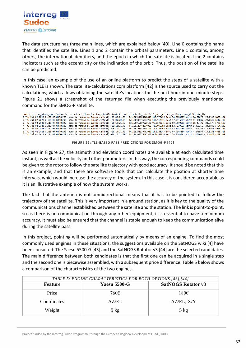
In this case, an example of the use of an online platform to predict the steps of a satellite with a
known TLE is shown. The satellite-calculations.com platform [42] is the source used to carry out the
calculations, which allows obtaining the satellite's locations for the next hour in one-minute steps.
Figure 21 shows a screenshot of the returned file when executing the previously mentioned
command for the SMOG-P satellite.
FIGURE 21: TLE-BASED PASS PREDICTIONS FOR SMOG-P [42]
As seen in Figure 27, the azimuth and elevation coordinates are available at each calculated time
instant, as well as the velocity and other parameters. In this way, the corresponding commands could
be given to the rotor to follow the satellite trajectory with good accuracy. It should be noted that this
is an example, and that there are software tools that can calculate the position at shorter time
intervals, which would increase the accuracy of the system. In this case it is considered acceptable as
it is an illustrative example of how the system works.
The fact that the antenna is not omnidirectional means that it has to be pointed to follow the
trajectory of the satellite. This is very important in a ground station, as it is key to the quality of the
communications channel established between the satellite and the station. The link is point-to-point,
so as there is no communication through any other equipment, it is essential to have a minimum
accuracy. It must also be ensured that the channel is stable enough to keep the communication alive
during the satellite pass.
In this project, pointing will be performed automatically by means of an engine. To find the most
commonly used engines in these situations, the suggestions available on the SatNOGS wiki [4] have
been consulted. The Yaesu 5500-G [43] and the SatNOGS Rotator v3 [44] are the selected candidates.
The main difference between both candidates is that the first one can be acquired in a single step
and the second one is piecewise assembled, with a subsequent price difference. Table 5 below shows
a comparison of the characteristics of the two engines.
TABLE 5: ENGINE CHARACTERISTICS FOR BOTH OPTIONS [43],[44]
Feature Yaesu 5500-G SatNOGS Rotator v3
Price
Coordinates
Weight
760€
AZ/EL
9 kg
180€
AZ/EL, X/Y
5 kg

Project funded by the Interreg Sudoe Programme through the European Regional Development Fund (ERDF)
33
Maximum vertical load
Torque (el, az)
Brake torque (el, az)
200 kg
14 kg/m, 6 kg/m
40 kg/m, 40 kg/m
Unknown
Unknown
18 kg/m, 18 kg/m
The price difference between the two models is evident. The model proposed by SatNOGS is lighter,
as it is intended to be portable in case the ground station should be moved to another location. This
is not a problem, as the idea is that the ground station remains permanently in place. An important
aspect is also the vertical load that it supports, so that there are no problems when moving the
antenna.
The Yaesu 5500-G rotor has been chosen for the project because it is easier to install, as it is available
in its totality in a single purchase. The choice of the other alternative requires individual purchase of
the various components and the assembly as a unit. The SatNOGS Rotator v3 option is therefore left
as a future alternative in case the station is registered on the platform and has access to the software
resources.
The Yaesu 5500-G engine has two possible operating modes, both of which can be useful depending
on the operation to be performed. The first option is the manual mode, which allows the antenna to
be oriented using switches on the control station. There are also two displays which indicate the
elevation and azimuth coordinates of the motor position. Figure 22 shows the layout of the
controllers:
FIGURE 22: YAESU 5500-G CONTROL INTERFACE [43]
There is also a way to control the motor externally as an alternative option. This functionality will be
used in the regular operation of the ground station, as it can be adapted to the pass prediction
defined in the previous section. To be able to do this, the Yaesu GS-232 interface [45] must be
installed, so that it can be connected to the computer via USB connector. Therefore, control software
is needed on the computer to transmit the appropriate commands so that the interface can send
them to the motor.

Project funded by the Interreg Sudoe Programme through the European Regional Development Fund (ERDF)
34
CONCLUSIONS AND FUTURE WORK
The main conclusion that can be extracted is that the design of the UHF receiving link for the
nanosatellite ground station has been completed, resulting in the three main blocks discussed below.
The first specific objective is the design of a receiving antenna operating in the UHF band. There is a
wide variety of solutions to this problem, and for this reason it has been decided to take two
previously tested solutions as a reference and adapt them to the characteristics of the project. In this
way, it can be concluded that the result allows the target band to be covered correctly, by means of
an antenna with a central frequency at 433 MHz and another at 437 MHz with different possibilities.
Regarding the design of the reception chain, the necessary components have been selected and the
signal quality delivered to the next block has been analyzed.
The second remarkable result is the signal processing system. The use of an SDR brings great flexibility
to the project and makes it possible to adapt the operation of the station to work with a single
satellite or to detect a set of satellites. Different demodulation and decoding schemes can be
implemented depending on the satellite detected, which is a great advantage. In addition, design
software is available to develop the scheme by means of a block diagram. The simulation has been
carried out on a Windows laptop, but the software will be installed on a Raspberri Pi 4 in the final
implementation. This will make it easier to use the GNU Radio Companion program, as it is optimized
to run on Linux systems.
The last of the three large blocks covers satellite tracking and pointing. In this section, the wide
availability of information on the web about the status of the various nanosatellites in orbit has been
used. The technology available allows easy and accurate calculation of future passes, which
significantly eases the task of tracking, although the information is dependent on third parties. For
pointing there are several possibilities, ranging from specific motors designed for the concrete
application to motor systems to be developed on a piece-by-piece approach. The positioning
information and the pointing system provide the necessary basis for the station to be able to track
visible satellites autonomously on a normal basis.
Once the design has been completed, installation should follow. This goal could not be completed.
The steps for implementation can be defined as follows:
• Selection of the satellite or group of satellites to be tracked, according to the conditions for
which the components are designed. Identification of the orbital parameters that allow their
tracking and the characteristics of their communications module.
• Development and installation of the antenna prototype with the receiving chain. The aim is
to test the performance in the least favorable case of the two evaluated. Alternatively, the
second designed prototype can be used.
• Integration of the antenna and the basic demodulation and decoding system for SDR testing.
For the functional tests it is suggested to perform the pointing manually.
• Software development that integrates satellite pass prediction with the action of the engine.
Installation of the receiving system and the automatic pointing system at the ground station.

Project funded by the Interreg Sudoe Programme through the European Regional Development Fund (ERDF)
35
In addition to the implementation of the design developed in this work, it is possible to add other
functionalities to the ground station. Firstly, an antenna can be added to establish a complementary
uplink to the already designed downlink. To do this, an antenna must be designed, which is suggested
to operate in the VHF band. This makes the ground station more adaptable to different scenarios and
allows it to work with different frequency bands.