NAILER/STAPLER - Power Tools Plus 57-7915 English - Rev … · Technical questions Replacement...
20
NAILER/STAPLER 057-7915-8 Owner’s Manual PRODUCT SPECIFICATIONS Rating: 120 V, 60 Hz AC Amperes: 5 A Switch: Single shot trigger with safety lock Repeat speed: Up to 20 shots per minute Staple size: T50 (1.25x0.6 mm) Crown: 3/8" (10.6 mm) Length: 1/4–5/8" (6–16 mm) Brad nail size: Gauge: 18 Length: 1/4–5/8” (6–16 mm) Magazine capacity: Up to 100 nails or staples Weight: 2 lb 3 oz (1.0 kg) Need Assistance? Call us on our toll free customer support line: 1-800-689-9928 Technical questions Replacement parts Parts missing from package Imported by Mastercraft Canada Toronto, Canada M4S 2B8
Transcript of NAILER/STAPLER - Power Tools Plus 57-7915 English - Rev … · Technical questions Replacement...

NAILER/STAPLER
057-7915-8
Owner’s Manual
PRODUCT SPECIFICATIONS
Rating: 120 V, 60 Hz AC
Amperes: 5 A
Switch: Single shot trigger with safety lock
Repeat speed: Up to 20 shots per minute
Staple size: T50 (1.25x0.6 mm) Crown: 3/8" (10.6 mm) Length: 1/4–5/8" (6–16 mm)
Brad nail size: Gauge: 18 Length: 1/4–5/8” (6–16 mm)
Magazine capacity: Up to 100 nails or staples
Weight: 2 lb 3 oz (1.0 kg)
Need Assistance? Call us on our toll free customer support line: 1-800-689-9928
Technical questions
Replacement parts
Parts missing from package
Imported by Mastercraft Canada Toronto, Canada M4S 2B8

2
Product specifications ………….……………………………………………………. 1 Table of contents ……………………………………………………………………... 2 General safety warnings …………………………………………………………….. 3–4 Eye, ear & lung protection …………………………………………………………… 3–4 Electrical safety ………………………………………………………………………. 4 Power tool safety ……………………………………………………………………... 5–6 General safety rules ………………………………………………………………….. 5 Work area ………………………………………………………………….………….. 5 Electrical safety ………………………………………………………………………. 5 Personal safety ……………………………………………………………………….. 5–6 Use and care of power tools .……………………………………………………….. 6 Service ………………………………………………………………………………… 6 Specific safety rules ………………………………………………………………….. 7 Extension cord safety ………………………………………………………….…….. 8 Symbols ……………………………………………………………………………….. 9 Know your nailer/stapler …………………………………………………………….. 10 Accessories and contents …………………………………………………………… 11 Assembly and operation …………………………………………………………….. 12–15 ON/OFF switch ……………………………………………………………………….. 12 Loading the tool with brad nails …………………………………………………….. 12–13 Loading the tool with staples ………………………………………………………... 13–14 Nailing or stapling …………………………………………………………………….. 14–15 Removing a jammed nail or staple …………………………………………………. 15 Maintenance ………………………………………………………………………….. 16 Exploded view ………………………………………………………………………... 17 Parts listing ……………………………………………………………………………. 18 Warranty ……………………………………………………………………….……… 19–20
TABLE OF CONTENTS

3
EYE, EAR & LUNG PROTECTION
This instruction manual includes the following:
General Safety Rules
Specific Safety Rules and Symbols
Functional Description
Assembly
Operation
Maintenance
Accessories
!
ALWAYS WEAR EYE PROTECTION THAT CONFORMS WITH CSA
REQUIREMENTS or ANSI SAFETY STANDARD Z87.1
FLYING DEBRIS can cause permanent eye damage. Prescription
eyeglasses ARE NOT a replacement for proper eye protection.
WARNING: Non-compliant eyewear can cause serious injury if
broken during the operation of a power tool.
SAVE THESE INSTRUCTIONS FOR REFERENCE
WARNING: Use hearing protection, particularly during extended
periods of operation of the tool, or if the operation is noisy. !
GENERAL SAFETY WARNINGS
CAUTION: Before using this tool or any of its accessories, read this
manual and follow all Safety Rules and Operating Instructions. !

4
ELECTRICAL SAFETY
WARNING: To avoid electrical hazards, fire hazards or damage to the
tool, use proper circuit protection.
This tool is wired at the factory for 120 V operation. It must be connected to
a 120 V, 15 A circuit that is protected by a time-delayed fuse or circuit
breaker. To avoid shock or fire, replace power cord immediately if it is worn,
cut or damaged in any way.
GENERAL SAFETY WARNINGS
WEAR A DUST MASK THAT IS DESIGNED TO BE USED WHEN
OPERATING A POWER TOOL IN A DUSTY ENVIRONMENT.
WARNING: Dust that is created by power sanding, sawing, grinding,
drilling, and other construction activities may contain chemicals that are known to cause cancer, birth defects, or other genetic abnormalities. These chemicals include:
Lead from lead-based paints Crystalline silica from bricks, cement, and other masonry products Arsenic and chromium from chemically treated lumber
The level of risk from exposure to these chemicals varies, according to how
often this type of work is performed. In order to reduce exposure to these
chemicals, work in a well-ventilated area, and use approved safety
equipment, such as a dust mask that is specifically designed to filter out
microscopic particles.
!
5
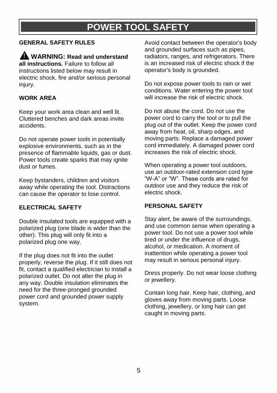
GENERAL SAFETY RULES
WARNING: Read and understand
all instructions. Failure to follow all
instructions listed below may result in electric shock, fire and/or serious personal injury. WORK AREA Keep your work area clean and well lit. Cluttered benches and dark areas invite accidents. Do not operate power tools in potentially explosive environments, such as in the presence of flammable liquids, gas or dust. Power tools create sparks that may ignite dust or fumes. Keep bystanders, children and visitors away while operating the tool. Distractions can cause the operator to lose control. ELECTRICAL SAFETY
Double insulated tools are equipped with a polarized plug (one blade is wider than the other). This plug will only fit into a polarized plug one way. If the plug does not fit into the outlet properly, reverse the plug. If it still does not fit, contact a qualified electrician to install a polarized outlet. Do not alter the plug in any way. Double insulation eliminates the need for the three-pronged grounded power cord and grounded power supply system.
Avoid contact between the operator's body and grounded surfaces such as pipes, radiators, ranges, and refrigerators. There is an increased risk of electric shock if the operator's body is grounded.
Do not expose power tools to rain or wet conditions. Water entering the power tool will increase the risk of electric shock.
Do not abuse the cord. Do not use the power cord to carry the tool or to pull the plug out of the outlet. Keep the power cord away from heat, oil, sharp edges, and moving parts. Replace a damaged power cord immediately. A damaged power cord increases the risk of electric shock.
When operating a power tool outdoors, use an outdoor-rated extension cord type “W-A” or “W”. These cords are rated for outdoor use and they reduce the risk of electric shock.
PERSONAL SAFETY
Stay alert, be aware of the surroundings, and use common sense when operating a power tool. Do not use a power tool while tired or under the influence of drugs, alcohol, or medication. A moment of inattention while operating a power tool may result in serious personal injury.
Dress properly. Do not wear loose clothing or jewellery.
Contain long hair. Keep hair, clothing, and gloves away from moving parts. Loose clothing, jewellery, or long hair can get caught in moving parts.
!
POWER TOOL SAFETY

6
PERSONAL SAFETY – cont’d
Avoid accidental start-ups. Verify that the switch is in the OFF position before plugging in the tool. Carrying a power tool with a finger on the switch or plugging in a tool that has the switch in the ON position invites accidents. Remove adjusting keys and wrenches before turning the tool ON. A wrench or key that is left attached to a rotating part of the tool may result in personal injury.
Do not overreach. Keep proper footing and balance at all times. Proper footing and balance allows the operator to maintain better control of the tool in unexpected situations. Use safety equipment. Always wear eye protection. Use a dust mask, non-skid safety shoes, a hardhat, or hearing protection when appropriate. USE AND CARE OF POWER TOOLS
Use clamps or another practical means to secure and support the workpiece to a stable platform. Holding the work in a hand or against the body is not stable, and may lead to loss of control. Do not force the tool. Use the correct tool for the application. The correct tool will do the job better and safer when used at the rate that it was designed to work at. Do not use a power tool if it cannot be turned ON or OFF using the power switch. A tool that cannot be controlled using the switch is dangerous, and must be repaired.
Disconnect the plug from the outlet before making any adjustments, changing accessories, or storing the tool. Such preventive safety measures reduce the risk of accidental start-ups. When power tools are not in use, store them out of the reach of children or untrained persons. Tools are dangerous in the hands of untrained users. Maintain tools with care. Keep cutting tools sharp and clean. Properly maintained cutting tools with sharp cutting edges are less likely to bind, and are easier to control. Inspect the tool for misalignment or binding of moving parts, broken parts, and any other condition that may affect the operation of the tool. If it is damaged, have the tool serviced before using it. Many accidents are caused by poorly maintained tools. Use only accessories that are recommended by the manufacturer for this model. Accessories that are suitable for one tool may become hazardous when used with another tool. SERVICE
Tool servicing must be performed by qualified personnel. Service or maintenance performed by non-qualified personnel could result in a risk of injury. When servicing a tool, use only identical replacement parts. Follow the instructions in the Maintenance section of this Manual. The use of unauthorized parts or failure to follow the instructions in the Maintenance section of this Manual may create a risk of electric shock or injury.
POWER TOOL SAFETY

7
WARNING: For your safety, do not
plug the tool into the power source or install nails or staples in your nailer/stapler until you have read and understood this Owner’s Manual.
DANGER: Never point the
nailer/stapler at anyone.
Always wear safety goggles or face mask. Use a dust mask along with safety goggles if the operation is dusty. Always use hearing protection, particularly during extended periods of operation. Do not wear gloves, neckties or loose clothing. Do not nail or staple any workpiece that is too small to be securely held. Always use a safe method to secure the workpiece, and use both hands to guide the tool. Never place your hands near or below the surface being nailed or stapled. Always keep your hands on the tool and not near the nail or staple mechanism. Avoid awkward hand positions where your hand could move into the path of the nail or staple. Hold the tool by its insulated gripping surfaces when performing an operation where the tool, nail or staple may contact hidden wiring or its own cord. Contact with a “live” wire will make exposed metal parts of the tool “live” and shock the operator.
Always make sure the work surface is free from nails and other foreign objects. Hitting a nail can cause the nail or staple to bend and the tool to jump. Never lay the workpiece on hard surfaces like concrete, stone, etc. Protruding nails or staples may cause the tool to jump. Always place the switch in the OFF position and remove the plug from the power source before adding or removing nails or staples from the magazine. Always place the switch in the OFF position and remove the plug from the power source before servicing the tool or removing a jammed nail or staple from the magazine.
SPECIFIC SAFETY RULES
!
!
SAVE THESE INSTRUCTIONS FOR REFERENCE
8
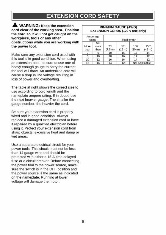
WARNING: Keep the extension
cord clear of the working area. Position the cord so it will not get caught on the workpiece, tools or any other obstructions while you are working with the power tool.
Make sure any extension cord used with this tool is in good condition. When using an extension cord, be sure to use one of heavy enough gauge to carry the current the tool will draw. An undersized cord will cause a drop in line voltage resulting in loss of power and overheating. The table at right shows the correct size to use according to cord length and the nameplate ampere rating. If in doubt, use the next heavier gauge. The smaller the gauge number, the heavier the cord. Be sure your extension cord is properly wired and in good condition. Always replace a damaged extension cord or have it repaired by a qualified electrician before using it. Protect your extension cord from sharp objects, excessive heat and damp or wet areas. Use a separate electrical circuit for your power tools. This circuit must not be less than 14 gauge wire and should be protected with either a 15 A time delayed fuse or a circuit breaker. Before connecting the power tool to the power source, make sure the switch is in the OFF position and the power source is the same as indicated on the nameplate. Running at lower voltage will damage the motor.
EXTENSION CORD SAFETY
! MINIMUM GAUGE (AWG)
EXTENSION CORDS (120 V use only)
Amperage rating
Total length
More than
Not more than
25' (7.5 m)
50' (15 m)
100' (30 m)
150' (45 m)
0 6 18 16 16 14
6 10 18 16 14 12
10 12 16 16 14 12
12 16 14 12 Not Applicable
9
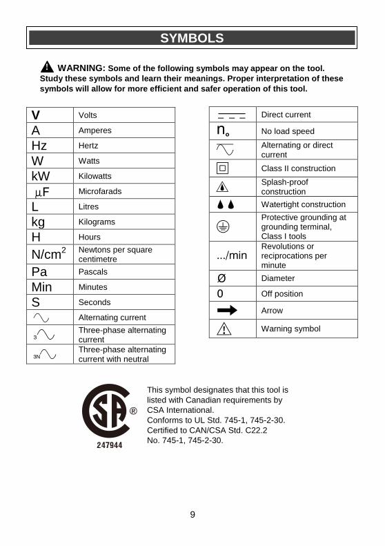
This symbol designates that this tool is
listed with Canadian requirements by
CSA International.
Conforms to UL Std. 745-1, 745-2-30.
Certified to CAN/CSA Std. C22.2
No. 745-1, 745-2-30.
V Volts
A Amperes
Hz Hertz
W Watts
kW Kilowatts
Microfarads
L Litres
kg Kilograms
H Hours
N/cm2 Newtons per square centimetre
Pa Pascals
Min Minutes
S Seconds
Alternating current
Three-phase alternating current
Three-phase alternating current with neutral
Direct current
No load speed
Alternating or direct current
Class II construction
Splash-proof construction
Watertight construction
Protective grounding at grounding terminal, Class I tools
Revolutions or reciprocations per minute
Diameter
Off position
Arrow
Warning symbol
SYMBOLS
WARNING: Some of the following symbols may appear on the tool.
Study these symbols and learn their meanings. Proper interpretation of these
symbols will allow for more efficient and safer operation of this tool.
!
10
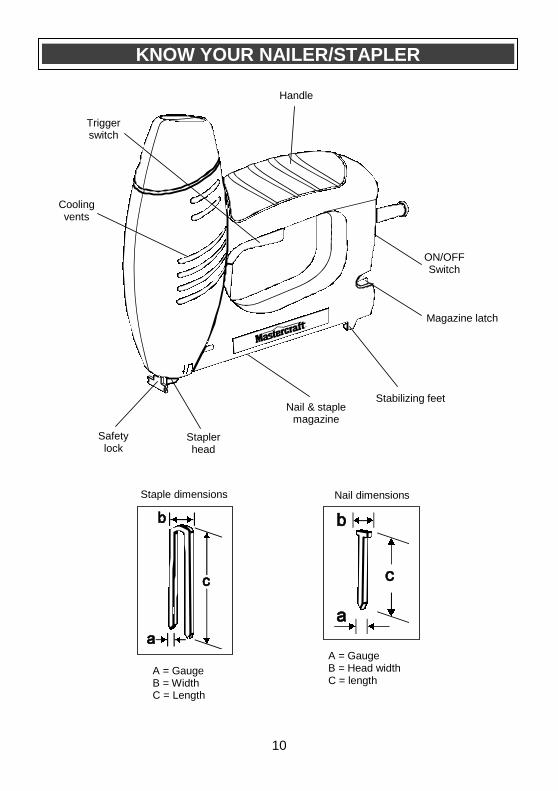
KNOW YOUR NAILER/STAPLER
A = Gauge B = Width C = Length
Staple dimensions
A = Gauge B = Head width C = length
Nail dimensions
Safety lock
Handle
Nail & staple magazine
Trigger switch
Cooling vents
Magazine latch
Stapler head
ON/OFF Switch
Stabilizing feet
11
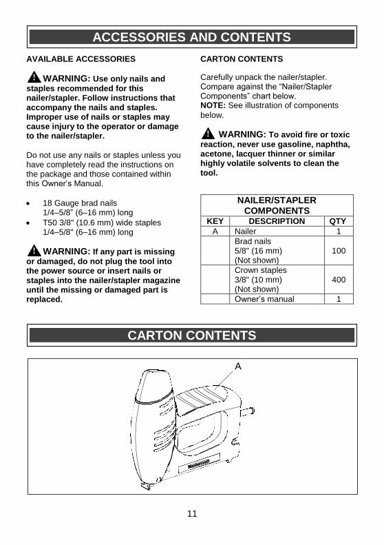
AVAILABLE ACCESSORIES
WARNING: Use only nails and
staples recommended for this nailer/stapler. Follow instructions that accompany the nails and staples. Improper use of nails or staples may cause injury to the operator or damage to the nailer/stapler.
Do not use any nails or staples unless you have completely read the instructions on the package and those contained within this Owner’s Manual.
18 Gauge brad nails 1/4–5/8” (6–16 mm) long
T50 3/8" (10.6 mm) wide staples 1/4–5/8" (6–16 mm) long
WARNING: If any part is missing
or damaged, do not plug the tool into the power source or insert nails or staples into the nailer/stapler magazine until the missing or damaged part is replaced.
CARTON CONTENTS
Carefully unpack the nailer/stapler. Compare against the “Nailer/Stapler Components” chart below. NOTE: See illustration of components
below. WARNING: To avoid fire or toxic
reaction, never use gasoline, naphtha, acetone, lacquer thinner or similar highly volatile solvents to clean the tool.
ACCESSORIES AND CONTENTS
CARTON CONTENTS
!
!
!
NAILER/STAPLER COMPONENTS
KEY DESCRIPTION QTY
A Nailer 1
Brad nails 5/8" (16 mm) (Not shown)
100
Crown staples 3/8" (10 mm) (Not shown)
400
Owner’s manual 1

12
ON/OFF SWITCH
The ON/OFF switch is located at the rear of the handle. To turn the tool ON, press the top of the ON/OFF switch (1) (Fig. 1). To turn the tool OFF, press the bottom of the ON/OFF switch (2). LOADING THE TOOL WITH BRAD NAILS
1. Turn the ON/OFF switch OFF and
remove the plug from the power source (Fig. 1).
2. Squeeze the magazine latch (1) (Fig. 2).
3. While squeezing on the magazine latch, slide the magazine out (2) as far as it will go (Fig. 3).
ASSEMBLY AND OPERATION
WARNING: For safety reasons, the operator must read the sections of this
Owner’s Manual entitled “GENERAL SAFETY WARNINGS”, “POWER TOOL SAFETY”, “SPECIFIC SAFETY RULES”, “EXTENSION CORD SAFETY” and “SYMBOLS” before using this nailer/stapler.
Verify the following every time the nailer/stapler is used:
1. Safety glasses are being worn. 2. Proper brad nails or staples are installed in the tool. 3. Workpiece is properly secured. 4. There are no “live” wires in the area where nails or staples are being driven.
Failure to adhere to these safety rules can greatly increase the chances of
injury.
!
Fig. 1
Fig. 3
Fig. 2

13
LOADING THE TOOL WITH BRAD NAILS – cont’d
4. Place a nail strip (2) into the magazine track (3) (Fig. 4).
NOTE: Place the heads of the nail strip (4)
into the magazine track first and lay the row of nails flat on the right hand side of the magazine track. 5. Slide the nail strip forward (5) to the
front of the magazine track.
6. Slide the magazine forward until the magazine latch locks the magazine into position.
NOTES:
a) If the magazine will not close properly, do not force it. Check to make sure the nail strip is properly nested flat against the right hand side of the magazine cavity. b) Make sure the magazine latch is fully engaged to prevent it from coming loose during operation. LOADING THE TOOL WITH STAPLES NOTE: This tool requires a specific type of
staples. Make sure you install T50 3/8" (10.6 mm) wide staples with a maximum length of 5/8” (16 mm). Other staples will not fit properly and may jam in the stapling mechanism. 1. Turn the ON/OFF switch to the OFF
position and remove the plug from the power source (Fig. 1).
2. Squeeze the magazine latch (1) (Fig. 2).
ASSEMBLY AND OPERATION
Fig. 4
Fig. 1
Fig. 2
14
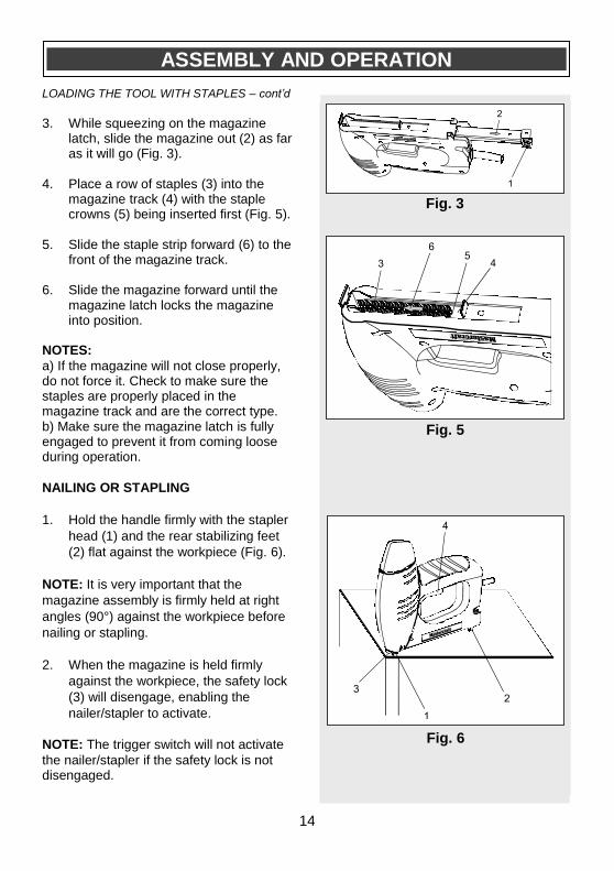
LOADING THE TOOL WITH STAPLES – cont’d 3. While squeezing on the magazine
latch, slide the magazine out (2) as far as it will go (Fig. 3).
4. Place a row of staples (3) into the
magazine track (4) with the staple crowns (5) being inserted first (Fig. 5).
5. Slide the staple strip forward (6) to the front of the magazine track.
6. Slide the magazine forward until the
magazine latch locks the magazine into position.
NOTES:
a) If the magazine will not close properly, do not force it. Check to make sure the staples are properly placed in the magazine track and are the correct type. b) Make sure the magazine latch is fully engaged to prevent it from coming loose during operation.
NAILING OR STAPLING
1. Hold the handle firmly with the stapler
head (1) and the rear stabilizing feet
(2) flat against the workpiece (Fig. 6).
NOTE: It is very important that the
magazine assembly is firmly held at right
angles (90°) against the workpiece before
nailing or stapling.
2. When the magazine is held firmly
against the workpiece, the safety lock
(3) will disengage, enabling the
nailer/stapler to activate.
NOTE: The trigger switch will not activate
the nailer/stapler if the safety lock is not disengaged.
ASSEMBLY AND OPERATION
Fig. 3
Fig. 5
Fig. 6

15
NAILING OR STAPLING – cont’d
3. Once the front of the nailer/stapler is
in the desired position, squeeze the
trigger switch (4) to drive the nail or
staple.
REMOVING A JAMMED NAIL OR
STAPLE
DANGER: Always turn the switch
OFF and remove the plug from the
power source before attempting to
remove a jammed nail or staple. This will
prevent accidental starting of the tool
which could result in serious injury.
1. Turn the switch OFF and remove the
plug from the power source.
2. Turn the tool upside down, press on
the magazine latch and slide the
magazine outward.
3. Remove unused nails or staples from
the magazine track.
4. Remove the jammed nail or staple from the mechanism with needle nose pliers.
NOTE: Remove the jammed nail or staple
immediately. Never attempt to drive a
second nail or staple once one has
jammed. Such action may damage the tool
mechanism and make removal of the
jammed nail or staple much more difficult.
ASSEMBLY AND OPERATION
!

16
GENERAL
WARNING: When servicing, use
only identical replacement parts. The
use of any other part may create a
hazard or cause damage to the product.
DO NOT use solvents when cleaning
plastic parts. Plastics are susceptible to
damage from various types of commercial
solvents and may be damaged by their
use. Use a clean cloth to remove dirt, dust,
oil, grease etc.
WARNING: Do not allow brake
fluids, gasoline, petroleum-based
products, penetrating oils, etc. to come
into contact with plastic parts. These
substances contain chemicals that can
damage, weaken or destroy plastic.
Remove accumulated dust and debris
regularly using a soft DRY brush.
WARNING: Use safety goggles when using an air jet to blow dust out of the tool.
DO NOT abuse power tools. Abusive
practices can damage the tool and the
workpiece.
WARNING: DO NOT attempt to
modify this tool or create accessories.
Any such alteration, modification or
unintended use is misuse and could
result in a hazardous condition leading
to possible serious injury. It will also
void the warranty.
LUBRICATION
All of the moving parts in this tool are
lubricated with a sufficient amount of high-
grade lubricant for the life of the unit under
normal conditions. Therefore, no further
lubrication is required.
!
!
!
MAINTENANCE
!
17
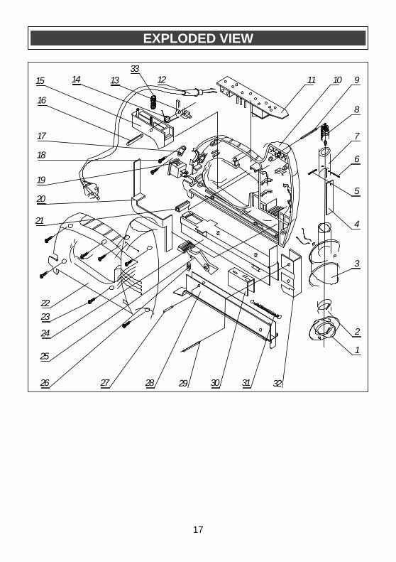
EXPLODED VIEW
0
1
2
3
4
5
6
7
8
9101115
16
17
18
19
20
21
22
23
24
25
26 27 30 31
14 13 12
28
33
29 32

18
WARNING: When servicing, use only Mastercraft® replacement parts. The use of
any other parts may create a safety hazard or cause damage to the tool. Any attempt to repair or replace electrical parts on this tool may create a safety hazard unless repairs are performed by a qualified technician. For more information, call the Toll-free Helpline, at 1-800-689-9928.
Always order by PART NUMBER, not by key number.
Key # Part # Part Name Quantity
1 J105-01 Dampening cup 1
2 J105-02 Dampening pad 1
3 J105-03 Loop 1
4 J105-04 Striking plate 1
5 J105-05 Pin 1
6 J105-06 Pin 1
7 J105-07 Solenoid core 1
8 J105-08 Tension spring 1
9 J105-09 Pin 1
10 J105-10 Left housing 1
11 J105-11 PCB 1
12 J105-12 Cord & plug 1
13 J105-13 Locking tab 1
14 J105-14 Twisted reed 1
15 J105-15 Switch trigger 1
16 J105-16 Pin 1
17 J105-17 Cord clamp 1
18 J105-18 Screw 2
19 J105-19 Switch 1
20 J105-20 Safety arm 1
21 J105-21 Steel hoop 1
22 J105-22 Right housing 1
23 J105-23 Screw 7
24 J105-24 Outer magazine channel 1
25 J105-25 Magazine lock 1
26 J105-26 Spring 1
27 J105-27 Pin 1
28 J105-28 Inner magazine channel 1
29 J105-29 Pin 1
30 J105-30 Nail pusher 1
31 J105-31 Nail pusher spring 1
32 J105-32 Nail channel 1
33 J105-33 Switch trigger spring 1
PARTS LIST
!

19
3-Year Limited Warranty This Mastercraft product is guaranteed for a period of 3 years from the date of original retail purchase against defects in workmanship and materials, except for the following components:
a) Component A: Batteries, chargers and carrying cases, which are guaranteed for a period of 2 years from the date of original retail purchase against defects in workmanship and materials;
b) Component B: Accessories which are guaranteed for a period of 1 year from the date of original retail purchase against defects in workmanship and materials.
Subject to the conditions and limitations described below, this product, if returned to us with proof of purchase within the stated warranty period and is covered under this warranty, will be repaired or replaced (with the same model, or one of equal value or specification),at our option. We will bear the cost of any repair or replacement and any costs of labour relating thereto. These warranties are subject to the following conditions and limitations:
a) A bill of sale verifying the purchase and the purchase date must be provided;
b) This warranty will not apply to any product or part thereof that is worn, broken or that has become inoperative due to abuse, misuse, accidental damage, neglect or lack of proper installation, operation or maintenance (as outlined in the applicable owner’s manual or operating instructions) or that is being used for industrial, professional, commercial or rental purposes;
c) This warranty will not apply to normal wear and tear or to expendable parts or accessories that may be supplied with the product that are expected to become inoperative or usable after a reasonable period of use;
d) This warranty will not apply to routine maintenance and consumable items such as, including but not limited to, fuel, lubricants, vacuum bags, blades, belts, sandpaper, bits, fluids, tune-ups or adjustments;
e) This warranty will not apply where damage is caused by repairs made or attempted by others (i.e.: persons not authorized by the manufacturer);
f) This warranty will not apply to any product that was sold to the original purchaser as a reconditioned or refurbished product (unless specified otherwise in writing);
Page 1 of 2

20
Rev 1.1 29/10/2009
3-Year Limited Warranty – cont’d These warranties are subject to the following conditions and limitations:
g) This warranty will not apply to any product or part thereof if any part from another manufacturer is installed therein or any repairs or alterations have been made or attempted by unauthorized persons;
h) This warranty will not apply to normal deterioration of the exterior finish, such as, including but not limited to, scratches, dents, paint chips, or to any corrosion or discoloring by heat, abrasive and chemical cleaners; and
i) This warranty will not apply to component parts sold by and identified as the product or company, which shall be covered under the product manufacturer’s warranty, if any.
Additional Limitations
This warranty applies only to the original purchaser, and cannot be transferred. Neither the retailer not the manufacturer shall be liable for any other expense, loss or damage, including, without limitation, but not limited to any indirect, incidental, consequential or exemplary damages arising in connection with the sale, use or inability to use this product. Notice to Consumer
This warranty gives you specific legal rights, and you may have other rights, which may vary from province to province. The provisions contained in this warranty are not intended to limit, modify, take away from, disclaim or exclude any statutory warranties set forth in any applicable provincial or federal legislation. Mastercraft is a superior line of products selected for their workmanship and materials. These products are designed to meet rigorous quality and performance standards, and are approved by our Quality Assurance laboratory.
TOLL-FREE HELPLINE: 1-800-689-9928
Page 2 of 2