
NACA RM E55GO2 - NASA
66
Transcript of NACA RM E55GO2 - NASA


NACA RM E55GO2
TABLE OF CONTENTS
PageSUMMARY. . . . . . . . . . . . . . . . . . . . . . . . . . . . . . 1
INTRODUCTION . . . . . . . . . . . . . . . . . . . . . . . . . . 1
PRELIMINARY CONSIDERATIONS . . . . . . . . . . . . . . . . . . . . 3Blade-Element Concept . . . . . . . . . . . . . . . . . . . . . . 3Factors Affecting Blade-Element Performance . . . . . . . . . . . 3
Incidence angle . . . ... . . . . . . . . . . . . . . . . . . . 3Total-pressure loss . . . . . . . . . . . . . . . . . . . . . . 4Deviation angle . . . . . . . . . . . . . . . . . . . . . . . . 5
Correlation Approach . . . . . 6Experimental Data Sources . . . 8
INCIDENCE-ANGLE ANALYSIS . . . . . . . . . . . . . . . . . . . . . 9Method of Correlation . . . . . . . . . . . . . . . . . . . . . . 9
NACA 65 (A10 ) -series blades . . . . . . . . . . . . . . . . . . 9
Double-circular-arc blade . . . . . . . . . . . . . . • • . 10Summary Remarks . . . . . . . . . . . . . . . . . . . . . . . . . 11
TOTAL-PRESSURE-LOSS ANALYSIS . . . . . . . . . . . . . . . . . 12Correlation of Data . . . . . . . . . . . . . . . . . . . . . . . 12Summary Remarks . . . . . . . . . . . . . . . .FA . . . . . . . . 13
DEVIATION-ANGLE ANALYSIS . . . . . . . . . . . . . . . . . . . . . 13Method of Correlation . . . . . . . . . . . . . . . . . . . . . . 14
NACA 65 (A10 ) -series blades . . . . . . . . . . . . . . . . . 15
Double-circular-arc blade . . . . . . . . . . . . . . . . . 16Summary Remarks . . . . . . . . . . . . . . . . . . . . . . . 16
APPLICATION TO DESIGN . . . . . . . . . . . . . . . . . . . . . . . 17Design Procedure . . . . . . . . . . . . . . . . . . . . . . . . 17Summary Remarks . . . . . . . . . . . . . . . . . . . . . . . . . 20
APPENDIXESA - SYMBOLS . . . . . . . . . . . . . . . . . . . . . . . . . . . 22
B - EQUATIONS FOR BLADE-ELEMENT EFFICIENCY . . . . . . ... . . . 25
REFERENCES .. . . . . . . • . . . . • . . . . . . • . • . • . 29
TABLE I - DETAILS OF SINGLE—STAGE ROTORS AND STATORS . . . . . . . 33
Restriction/Classification Cancelled
Restriction/Classification Cancelled

NACA RBI E55G02
NATIONAL ADVISORY COMMITTEE FOR AERONAUTICS
RESEARCH MEMORANDUM!
AERODYNAMIC DESIGN OF AXIAL-FLOW COMPRESSORS
VII - BLADE-ELEMENT FLOW IN ANNULAR CASCADES
By William H. Robbins, Robert J. Jackson, and Seymour Lieblein
SUMMARY
A blade-element analysis is made of annular-cascade data obtainedprimarily from single-stage compressor test installations. The parametersthat describe blade-element flow (total-pressure loss, incidence angle,and deviation angle) are discussed with reference to the many variablesaffecting these parameters. The blade-element data axe correlated over afairly wide range of inlet Mach number and cascade geometry. Two bladeshapes are considered in detail, the 65-series profile and the double-circular-arc airfoil® Compressor data at three radial positions near thetip, mean, and hub are correlated at minimum-loss incidence angle. Curvesof loss, incidence angle, and deviation angle are presented for rotor andstator blade elements® These correlation curves are presented in such amanner that they are directly related to the low-speed two-dimensional-cascade results. As far as possible, physical explanations of the flowphenomena are presented. In addition, a calculation procedure is givento illustrate how the correlation curves could be utilized in compressordesign.
INTRODUCTION
Axial-flow-compressor research has generally been directed towardthe solution of either compressor design or compressor analysis problems.In the design problem, the compressor-inlet and -outlet conditions aregiven, and the compressor geometry must be determined to satisfy theseconditions. In contrast, for the analysis problem the inlet conditionsand compressor are specified, and the outlet conditions are desired.(The analysis problem is sometimes referred to as the "direct compressorproblem.")
There are two phases of the axial-flow-compressor design problem.In the first phase it is necessary to prescribe desirable velocity dis-tributions at each radius of the compressor that will ultimately fulfillthe design requirements. A detailed discussion of the velocity-diagram
CONFI
Restriction/Classification Cancelled
Restriction/Classification Cancelled

2 CONFIDENTIAL NACA RM E55GO2
phase of the compressor design procedure is given in reference 1. Second-ly, proper blade sections are selected at each radial position and stackedin proper relation to each other to establish the design velocity diagramsat each radius. In order to satisfy the design requirements successfully,accurate blade row design data are needed. Successful analysis of a com-pressor (the analysis problem) also depends upon accurate blade-row data,not only at the design point but also over a wide range of flow conditions(ref. 2).
In general, compressor designers have relied primarily on threesources of blading information: ' (1) theoretical (potential-flow) solu-tions of the flow past airfoil cascades, (2) low-speed two-dimensional-cascade data, and (3) three-dimensional annular-cascade data. Potential-flow solutions have been used to a limited extent. In order to handlethe complex mathematics involved in the theoretical solutions, it is nec-essary to make simplifying assumptions concerning the flow field. Amongthe most important of these is the assumption of a two-dimensional flowfield with no losses. Unfortunately, in some cases these assumptions leadto invalid results unless experimental correction factors axe applied tothe computed results. These solutions are reviewed in reference 3.
A considerable amount of blade design data has been obtained fromlow Mach number .experimental two-dimensional cascades. A rather completehistory of the cascade work that has been done to date is presented inreference 4, which correlates cascade data at minimum.-loss incidence anglefor a wide range of inlet conditions and blade loadings. Low speed two-dimensional-cascade data have been applied successfully in many compressordesigns. However, with the design trends toward higher Mach numbers andhigher blade loadings, these cascade results have not always been com-pletely adequate for describing the compressor flow conditions, particu-larly in regions of the compressor where three-dimensional flow effectspredominate.
Because of such effects, it becomes essential that blade-element databe obtained in a three-dimensional compressor environment. These three-dimensional-cascade data (obtained primarily from single-stage compressors)may then be used to supplement and correct the theoretical solutions andthe two-dimensional-cascade information. Some success has been obtainedin correlating annular-cascade data with the theory and the two-dimensional-cascade results (refs. 5 to 9); however, the range of varia-bles covered in these investigations is not nearly complete.
The purpose of this report is to correlate and summarize the availa-ble compressor data on a blade-element basis for comparison with the two-dimensional-cascade data of reference 4. 'An attempt is made to Indicatethe regions of a compressor where low-speed two-dimensional-cascade datacan be applied to compressors and also to indicate the regions where cas-cade results must be modified for successful application to compressor
CONFIDENTIAL

NACA RM E55G02 CONFIDENTIAL 3
design. Two blade sections are considered in detail, the NACA 65-seriesblade and the double-circular-arc airfoil section. Particular emphasisis placed on obtaining incidence angle, deviation angle, and loss corre-lations at minimum loss for blade elements near the hub, mean, and tipradii of both rotor and stator blades. Empirical correction factors thatcan be applied to the two-dimensional-cascade design rules are given, andapplication of the design rules and correction factors to compressor de-sign is illustrated.
PRELIMINARY CONSIDERATIONS
Blade-Element Concept
In current design practice, the flow distribution at the outlet ofcompressor blade rows is determined from the flow characteristics of theindividual blade sections or elements® The blade-element approach tocompressor design is discussed in detail in references 10 and 11. Toreview briefly, axial-flow-compressor blades are evolved from a processof radial stacking of individual airfoil shapes called blade elements.The blade elements are assumed to be along surfaces of revolution gener-ated by rotating a streamline about the compressor axis; this stream sur-face of revolution may be approximated by an equivalent cone (fig, 1).Each element along the height of the blade is designed to direct the flowof air in a certain direction as required by the design velocity diagramof the blade row® The basic parameters defining the flow about a bladeelement are indicated in figure 2. Stated simply, blade-element-flow isdescribed by the variations of the loss in total pressure across the bladerow and of the air turning angle with the incidence angle (or angle ofattack).
Factors Affecting Blade-Element Performance
The flow about a given blade element in a compressor configurationis different from that in a two-dimensional cascade because of three-dimensional effects in compressor blade rows. These three-dimensionaleffects influence the magnitude of the design incidence angle, the lossin total pressure, and the deviation angle.
Incidence angle. - In the low-speed two-dimensional cascade, theminimum-loss incidence angle depends on the blade geometry (camber, so-lidity, and blade thickness), the inlet-air angle, and inlet Mach number(ref. 4)a In compressor operation, several additional factors can alterthe minimum-loss incidence angle for a given element geometry - for ex-ample, differences in testing procedure. In compressor operation, inci-dence angle, inlet-air angle, and inlet Mach number vary simultaneously,in contrast, cascades are often operated with fixed inlet-air angle and
CONFIDENTIAL

4 CONFIDENTIAL NACA RM E55GO2
inlet Mach number. Some net difference in the range characteristics and,therefore, the location of the point of minimum. loss between cascade oper-ation at constant inlet-air angle and compressor test operation (withvarying inlet-air angle) may be obtained.
In addition to these blade-element considerations, of course, thereare sources of difference arising from compressor three-dimensional ef-fects. For example, a change of minimum-loss.incidence angle has beenobserved in the compressor rotor as radial position is varied (refs. 12and 13), but .cascade and compressor blade-element minimum-loss incidenceangles have not been compared over a wide range of blade loadings and in-let Mach numbers.
Total-pressure loss. - In the two-dimensional cascade, the magnitudeof the loss in total pressure across the blade element is determined fromthe growth of the blade-surface boundary layers (profile loss). In theactual compressor, the loss in total pressure is determined not only bythe profile loss, but also by the losses induced by the three-dimensionalnature of the flow. These three-dimensional losses result from secondarymotions and disturbances generated by the casing wall boundary layers,from blade tip clearance, from radial gradients of total energy, and frominteractions of adjacent blade rows. The compressor loss picture is fur-ther complicated by the tendency of boundary-layer fluid on the compres-sor blade surfaces and in the blade wake to be displaced radially. As aconsequence of this phenomenon, the loss measured downstream of a givenblade element may not necessarily reflect the actual loss generated atthat element, but something more or less, depending on the radial loca-tion of the element.
It is expected, therefore, that the factors influencing the magni-tude of the blade-element loss in the compressor will include the factorsaffecting the profile loss (blade-surface velocity distribution, inletMach number, blade-chord Reynolds number, free-stream turbulence, andblade surface finish) and the factors affecting the three-dimensionallosses. Investigations of compressor blade-element losses based on sur-face velocity distribution, as expressed in terms of diffusion factors,are presented in references 14 and 15. The essentially secondary effectsof blade surface finish and trailing-edge thickness on compressor lossare investigated in references 16 and 17. Results of tests of blade--element performance (ref. 18) and over-all performance (refs. 19 to 21)at varying Reynolds numbers indicate that there is no significant varia-tion in loss for Reynolds numbers above approximately 2.5x10⁵ . (Sincemost of the compressor data used in this analysis are for Reynolds num-bers greater than 2.5x10⁵, no Reynolds number effects are believed toexist for the data.) The variations of compressor loss with inlet Machnumber have been established in references 12, 22, and 23. These results,however, are not complete indications of Mach number effects (shocklosses), since the corresponding variations of blade diffusion with, Mach
CONFIDENTIAL

NACA RM E55GO2 CONFIDENTIAL 5
number are not identified. An attempt to separate the variation of dif-fusion and shock losses with Vlach number by means of an analysis based onthe diffusion factor of reference 14 is presented in references 13 and 24.
Although some aspects of the compressor three-dimensional flow phe-nomena are known (refs. 25 and 26), the specific factors or parametersaffecting compressor three-dimensional losses have not been establishedfor analysis purposes. At present, the three-dimensional loss can betreated only on a gross basis as a difference between the total measuredloss and the predicted profile loss.
Deviation angle. - In the two-dimensional cascade the minimum-lossdeviation angle varies primarily with the blade geometry and the inlet-air angle. Experience with compressor operation indicates that blade-element minimum-loss deviation angle is also sensitive to three-dimensional effects. The two principal compressor effects are secondaryflows and changes in axial velocity across the blade element. Secondaryflows are treated in references 26 and 27. Corrections are establishedin reference 27 fqr the effect of secondary flows on the outlet anglesof compressor inlet guide vanes. At present, however, rotor and statorsecondary-flow effects can be treated only on a gross basis.
The effects of changes in axial-velocity ratio on the turning anglesof a fixed blade-element geometry are conclusively demonstrated in therotor investigations of reference 7. There are several origins of vary-ing axial-velocity ratio across a compressor blade element: (1) contrac-tion of the annulus area across the blade row, (2) compressibility, whichvaries axial-velocity ratio for a fixed annulus area ' and (3) differencesin the radial gradient of axial velocity at blade-row inlet and outlet,which can arise from the effects of radial pressure equilibrium (ref. 1).Although several attempts have been made to establish corrections for theeffect of change in axial-velocity ratio on deviation angle (refs® 7 and28), these proposed correction techniques have not been universally suc-cessful. The principal difficulty involved in the axial-velocity correc-tions is the inability to determine the corresponding changes in bladecirculation (i.e., tangential velocity). Values of axial-velocity ratiowere identified for the deviation angle data presented, although no at-tempt was made to apply any corrections.
Some of the secondary factors influencing deviation angle, such asinlet Mach number and Reynolds number, axe investigated in references 7,12, and 22. These results indicate that the variations of deviationangle with Mach number and Reynolds number (as in the two-dimensionalcascade) are small.
CONFIDENTT.AL

6 CONFIDENTIAL NACA RM E55GO2
Correlation Approach
In this report, annular-cascade data are compared with the two-dimensional-cascade correlations of minimum loss-incidence angle, total-pressure loss, and deviation angle (ref. 4). In this way, compressorinvestigations serve as both a verification and an extension of the two-dimensional-cascade data. Tvo--dimensional®cascade data correlations andrules, in conjunction with correction factors deduced from the three-dimensional data, can then be used for compressor design and analysis.
With this approach in mind, all available single-stage data werecollected, computed, and plotted in a form considered convenient for cor-relation. The blade and performance parameters used in the analysis aresimilar to those used in the two-dimensional-cascade correlations of ref-erence 4. Camber angle, incidence angle, and deviation angle (fig. 2)are used to define the blade camber, air approach, and air leaving direc-tions, respectively. These angles are based on tangents to blade meancamber line at the leading and trailing edges As in reference 4, theNACA 65(Al0 )-series blades are considered in terms of the equivalentcircular-arc camber line (figs. 3 and 4).
Loss in total pressure across the blade element is expressed in termsof the loss parameter E cos 2ar, where the relative total-pressure losscoefficient E is defined as the mass-averaged defect in relative totalpressure divided by the pressure equivalent of the inlet velocity head;
P2,id - P2 (1)
Pl - pl
(All symbols are defined in appendix A.) For stationary blade rows; orno change in streamline radius across the rotor, the numerator of equa-tion (1) becomes the.decrease in relative total pressure across the bladerow from inlet to outlet. The relative total-pressure-loss coefficientwas computed from stationary measurements of total pressure and total tem-perature and from the computed relative inlet ]Mach number according toreference 14. The total-pressure-loss parameter, as indicated in refer-ence 4, approximates the individual blade wake momentum-thickness ratio8/c and as such represents a significant parameter for correlating bladelosses.
CONFIDENTIAL

NACA RM E55G02 CONFIDENTIAL 7
The diffusion factor, which is used as a blade-loading parameter, isdefined in reference 14 as follows:
D - 1 - V + Vb, 2c- %2(2)
1 1
A typical example of the plotted performance parameters for a rotorblade row is shown in figure 5. The data represent the variations of theflow at fixed rotational speed. Plots for stator blade rows show similartrends of variation. As in reference 4, a reference point was establishedas the incidence angle for minimum loss (fig. 6(a)), and the blade-elementflow was analyzed at this reference point. In cases where minimum-lossincidence was not clearly defined, the reference point was taken as themean incidence of the incidence-angle range for which values of 5; at theend points are twice the minimum value (fig. 6(b)).
One of the primary objectives of this analysis is to determine dif-ferences in blade-element performance with compressor radial position.Therefore, three radial positions along the blade span (near the hub,mean radius, and tip) of each blade row are considered. The radial posi-tions at the hub and tip are approximately 10 to 15 percent of the pas-sage height away from the inner and outer walls ., respectively, which areoutside the wall boundary-layer region in all cases® 'The analysis isdirected toward correlating the loss and deviation-angle data at refer-ence incidence angle and determining the variation of reference incidenceangle with blade geometry and Mach number at the three radial po=sitions.
*In a communication to the authors ., Dr. Leroy Smith, Jr. of theGeneral Electric Company has suggested that in the presence of a changein radius across a blade element, the diffusion factor for the rotor begiven by
V, A(rVe)DR 1 -
Vl + 2cav av 1
where rav is the average radius between inlet and outlet, cav is thecorresponding average solidity, and Ve is the absolute tangential ve-locity. Other terms are as before. For the stator,
V2 A(rVe)S = 1
VT) 2cavravVl
Spot checks of hub-position velocity diagrams, where the change in radiusis the greatest for the rotors considered, showed small differences be-tween the values of D computed from equation (2) and from these modi-fied relations.
CONFIDENTIAL

8 CONFIDENTIAL NACA RM E55GO2
Experimental Data Sources
There are three sources of three-dimensional-cascade blade-elementdata: stationary annular-cascade tunnel investigations, multistage-compressor investigations, and single-stage or single-blade-row compressorinvestigations. A relatively small amount of data has been accumulatedfrom blade-row investigations conducted in stationary annular-cascade tun-nels. Tunnels of this type have been used primarily for inlet-guide-vaneinvestigations. Typical examples of annular-cascade tunnel investigationsare reported in references 18 and 29. Numerous multistage compressor in-vestigations have been conducted both in this country and abroad. Unfor-tunately, the data obtained from these investigations are too limited topermit the construction of individual blade-row-element performance curvessimilar to those illustrated in figure 5.
The data used in this investigation were obtained primarily from in-vestigations of single rotor rows or of single-stage compressors. A typ-ical single-stage compressor test installation is .shown in figure 7. Thisparticular compressor consists of a row of inlet guide vanes, a rotorblade row driven by a variable-speed motor, and a stator blade row. Adischarge throttle is installed in the outlet system to vary the compres-sor back pressure. In this manner, the compressor mass -flow rate can becontrolled. In an installation such as this, compressor performance overa range of speeds and mass flows can be obtained simply. In many cases,test rigs similar to figure 7 have been operated with only guide vanesand rotors or with rotors alone.
Many phases of -compressor research have been conducted in single-stage compressor test rigs; and, in reporting these phases, completeblade-element results are not usually presented. Therefore, it was nec-essary to collect available original data and rework them in terms of theparameters of the analysis. Since only NACA original data were availablein blade-element form, the data analysis is based mainly on single-stagecompressor investigations conducted at the Lewis laboratory. The measure-ments taken and the instrumentation used vary somewhat from compressor tocompressor; in most cases, however, it is possible from the available datato reconstruct complete experimental velocity diagrams and to determinethe blade-element performance. Radial and circumferential survey measure-ments were made after each blade row. Normally, total pressure, staticpressure, total temperature, and air direction were measured. Thepressure- and temperature-measuring devices were calibrated for the effectof Mach number.
Most of the compressor investigations that were adaptable to thisanalysis were conducted on NACA 65-series airfoil shapes and double-circular-arc airfoils. Therefore, the analysis is concerned solely withthese airfoils. The 65-series airfoil has been used extensively in sub-sonic compressors; and the double-circular--arc airfoil, which is a rela-tively simple airfoil shape, has been used effectively in transonic com-pressors. Details of the characteristics of the various blade rows used
CONFIDENTIAL
NACA RM E55GO2 CONFIDENTIAL 9
in this analysis are summarized in table I, and details of the instrumen-tation, calculation procedure, and accuracy of measurement are given inthe listed references.
INCIDENCE-ANGLE ANALYSIS
Method of Correlation
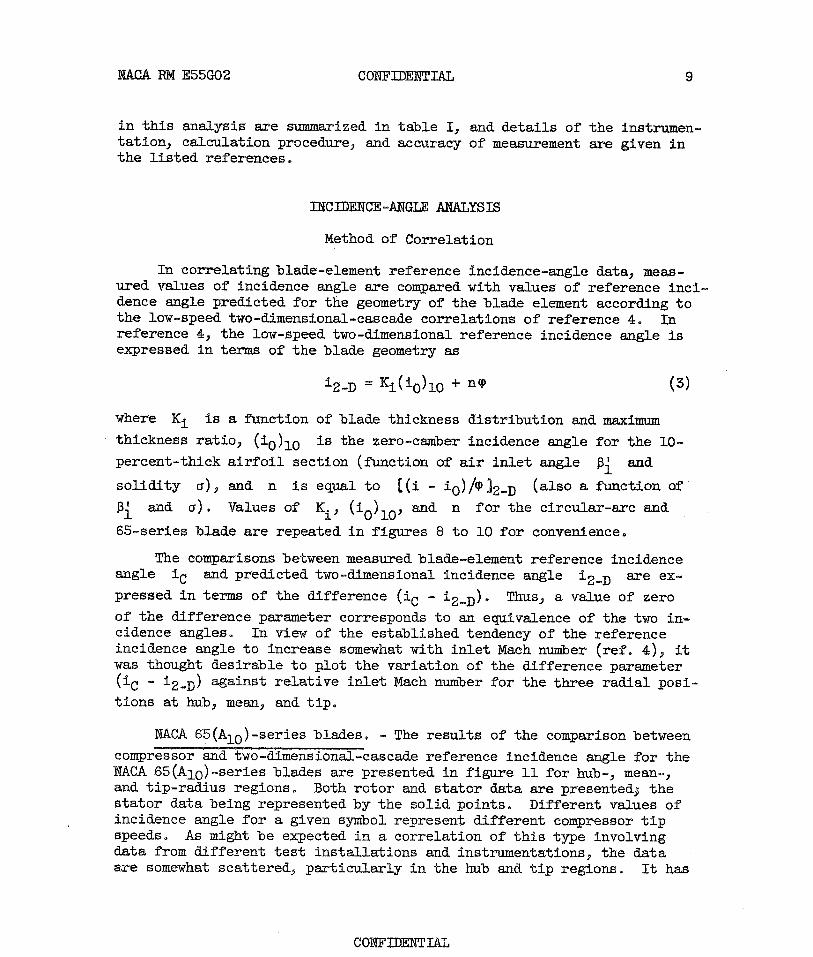
In correlating blade-element reference incidence-angle data, meas-ured values of incidence angle are compared with values of reference inci-dence angle predicted for the geometry of the blade element according tothe low-speed two-dimensional-cascade correlations of reference 4. Inreference 4, the low-speed two-dimensional reference incidence angle isexpressed in terms of the blade geometry as
i2-D = Ki (iO ) 1O + nq (3)
where Ki is a function of blade thickness distribution and maximumthickness ratio, (iO )lO is the zero-camber incidence angle for the 10-percent-thick airfoil section (function of air inlet angle and
solidity a) , and n is equal to 1(i - iO) A0,2-D (also a function of¢i and a). Values of Ki , (i0)10' and n for the circular-arc and
65-series blade are repeated in figures 8 to 10 for convenience.
The comparisons between measured blade-element reference incidenceangle iC and predicted two-dimensional incidence angle 12-D are ex-pressed in terms of the difference (i C - i2 D). Thus, a value of zeroof the difference parameter corresponds to an equivalence of the two in-cidence angles. In view of the established tendency of the referenceincidence angle to increase somewhat with inlet Mach number (ref. 4), itwas thought desirable to plot the variation of the difference parameter(iC - 12-D ) against relative inlet Mach number for the three radial posi-tions at hub, mean, and tip.
NACA 65(Alo)-series blades® - The results of the comparison between
compressor and two-dimensional-cascade reference incidence angle for theRACA 65(AlO)-series blades are presented in figure 11 for hub-, mean-,and tip-radius regions. Both rotor and stator data are presented; thestator data being represented by the solid points. Different values ofincidence angle for a given symbol represent different compressor tipspeeds. As might be expected in a correlation of this type involvingdata from different test installations and instrumentations, the dataare somewhat scattered, particularly in the hub and tip regions. It has
CONFIDENTIAL

10 CONFIDENTIAL NACA RM E55GO2
not been possible in these instances to evaluate the significance or ori-gin of the scatter. (In compressor investigations, instrumentation in-accuracy generally contributes heavily to the data scatter ., especially athub and tip.) Nevertheless, the results of the comparison are indicativeof the trends involved, and it is possible to make some generalobservations.
For the rotor mean-radius region, where three-dimensional disturb-ances are most likely a minimum, the rotor minimum.-loss incidence anglesare, on the averages about 10 smaller than the corresponding cascade-predicted values. This difference may be a reflection of some of thecompressor influences discussed previously. The data also indicate thatno essential variation of reference incidence angle with relative inletMach number exists up to values of Ml of about 0.8. The 65-series
blade, having a thick nose profile, apparently exhibits the same approx-imate constancy of minimum-loss incidence angle with Mach number as in-dicated for the British thick-nose C4-series profile in the cascade com-parisons of reference 4.
At the rotor tip' the compressor reference incidence angles are from00 to 40 less than the predicted cascade values. As in the case of therotor mean radius,, no essential variation with inlet Mach number is ob-served in the range of data covered. The lower values of rotor referenceincidence angle were generally the result of a change in the form of thevariations of loss incidence angle in the rotor, as illustrated in figure12. The change in form may be explained on the basis of a probable in-crease in rotor tip three-dimensional losses (centrifuging of bladeboundary layer, tip-clearance disturbances, etc.) with increasing inci-dence angle.
At the rotor hub, the situation is somewhat confused by the widerange of data. A tendency of the compressor incidence angles to be some-what larger than the corresponding cascade values with an average valueof about 10 or 20 is indicated.
For the stator mean radius and hub regions, close agreement betweencompressor and cascade incidence angles is indicated for the range ofMach numbers covered (to about 0.7). Considerable scatter exists in thestator data at the compressor tip; therefore, no definite conclusions canbe made concerning the variations of incidence angle.
Double-circular-arc blade. - The results of the double-circular-arcairfoil correlation are presented in figure 13, where compressor refer-ence incidence angle minus low-speed cascade-rule incidence angle (eq.(3)) is plotted against relative inlet Mach number for the hub, mean, andtip radial positions for both rotors and stators. The dashed curve rep-resents the variation obtained with a 25 0-camber double-circular-arc bladein high-speed two-dimensional cascade (ref. 4).
CONFIDENTIAL

NACA RM E55G02 CONFIDENTIAL 11
It is immediately apparent that rotor reference incidence angle atall radial positions increases with increasing Mach number. The dataindicate that the magnitude of the increase in reference incidence anglewith Mach number is larger at the hub than at the tip. The hub datapoints in figure 13 were obtained from blade elements of relatively highcamber. Both potential-flow and low-speed cascade results indicate thatthis type of configuration is associated with a negative value of refer-ence incidence angle. As inlet Mach number is increased, the rate ofchange of incidence angle in the positive direction must be fairly largein order to avoid high losses associated with blade-row choking, explainedin detail in reference 4. In contrast, at the compressor tip, since theblade cambers are generally lower (see table I), the low-speed incidenceangle is higher and the required rate of change of incidence angle withincreasing Mach number is not as large. Unfortunately, low Mach numberdata were not available to permit extrapolation of the rotor incidence-angle variations to zero Mach number (level of cascade correlation).However, it is believed that there will be very little change in the rotorincidence angle for values of Mach number below about 0.4 to 0.5. Extra-polated values of rotor reference incidence angle at zero Mach number ap-pear to be of the order of 0.5 0 at the hub, 1_.50 at the mean radius, and2.50 at the tip below cascade-rule values.
The double-circular-arc blade element in the compressor rotor exhib-its the same general incidence-angle characteristic with Mach number thatwas observed for sharp-nosed blade sections in the high-speed two-dimensional cascade (ref. 4). As indicated in reference 4, the increasein reference incidence angle with Mach number is associated with the tend-ency of the range of the blade to be reduced only on the low-incidenceside of the loss curve as Mach number is increased.
The rotor data for the double-circular-arc section, like those forthe 65-series blades, are comparable to the cascade variations at themean radius, somewhat higher at the hub at the higher Mach numbers, andnoticably lower at the tip. Apparently, the same type of three-dimensional phenomenon occurs at the tip for both blade shapes.
The available double-circular-arc stator data are too meager forany conclusions.
Summary Remarks
The variation of reference incidence angle for 65-series and double-circular-arc blade sections has been presented. No Mach number effect onreference incidence angle was observed for the 65-series blades for therange of Mach numbers considered. In contrast, the double-circular-arcblade sections exhibit a pronounced variation of reference incidenceangle over the range of Mach number investigated. Significant differences
CONFIDENTIAL

12 CONFIDENTIAL WACA RM E55GO2
between the low-speed-cascade data and the rotor data were observed atthe compressor tip. In contrast, at the mean radius and hub, the differ-ences in two-dimensional-cascade data and rotor data were relativelysmall, even though the flow field was three-dimensional.
Additional data are required to determine the variation of statorreference incidence angle, particularly for the double-circular-arc air-foil sections. Also, no information has been presented concerning theallowable incidence-angle range for efficient (low-loss) operation andthe variation of this range with inlet Mach number. Investigations ofthese phases of compressor research are very essential to fill gaps inthe compressor design and analysis procedures and warrant attention infuture research programs.
TOTAL-PRESSURE-LOSS ANALYSIS
Correlation of Data
For two-dimensional-cascade data obtained at low Mach numbers, thevalues of total-pressure-loss parameter w cos 02/2a plotted against
diffusion factor (eq. (2)) form essentially a single curve for all cas-cade configurations. The diffusion-factor correlation of loss parameterwas applied to data obtained over a range of Mach numbers from single-.stage axial-flow compressors of various geometries and design Mach num-bers. Values of total-pressure-loss parameter calculated from single-stage compressor data are plotted against diffusion factor for the hub,mean, and tip measuring stations in figure 14. Each symbol representsthe value of diffusion factor and loss parameter at reference incidenceangle at a given tip speed. Also plotted as a dashed curve is the cor-responding correlation presented in reference 4 for the low-speed two-dimensional-cascade data. The data of figure 14, which were obtainedfrom the rotor and stator configurations summarized in table I, representboth 65-series and circular-arc blade sections. The plots of figure 14essentially represent an elaboration of the loss-diffusion correlationsof reference 14.
The most important impression obtained from the rotor data plots isthe wide scatter and increasing loss trend with diffusion factor at therotor tip, while no discernible trend of variation is obtained at therotor hub and mean radii. For the rotor hub and mean radii, it can beassumed that the rotor blade-element loss parameter follows the cascadevariation but at a higher average magnitude. Unfortunately, the rangeof diffusion factor covered in the compressor tests was not sufficientto determine whether a marked rise in loss is obtained for values of dif-fusion factor greater than about 0.6 (as in the cascade).
CONFIDENTIAL

NACA RM E55GO2 CONFIDENTIAL 13
It is apparent from the loss trend and data scatter at the rotortip that a different loss phenomenon is occurring in the tip region. Itis recognized that a part of the scatter is due to the general instrumen-tation inaccuracy in the highly turbulent tip regions. In view of theusually large radial gradients of loss existing in the blade tip region,small variations in positioning radial survey probes can cause noticeabledifferences in the computed results. Nevertheless, it is obvious thatfactors other than the blade-element diffusion are influencing the tiploss. The specific three-dimensional factors or origins involved in thelow rise at the tip are not currently known. The principal conclusionreached from the plot is that the likelihood of a rising loss trend onthe rotor tip exists for values of diffusion factor greater than about0.35.
The stator losses at all radial positions in figure 14 appear to besomewhat higher than those of the two-dimensional cascade, particularlyat the higher values of diffusion factor.
Summary Remarks
Rotor and stator blade-element loss data were correlated by meansof the diffusion factor. The losses for stator and rotor blade elementsat hub and mean radii were somewhat higher than those for the two-dimensional cascade over the range of diffusion factor investigated. Atthe rotor tip, the losses were considerably higher at values of diffusionfactor above approximately 0.35.
The foregoing blade-element loss analysis is clearly incomplete.The need for additional work is indicated for such purposes as evaluatingthe origin and magnitude of the tip-region losses. The loading limitsfor rotors at other than the tip region and for stators at all blade ele-ments have not been determined, because, for the available data, the dif-fusion factors at reference incidence do not extend to sufficiently highvalues. Single-stage investigations are needed over the critical range ofReynolds number to determine the effect of Reynolds number on the blade-element loss. It is desirable to isolate the effects of velocity diffu-sion and shock waves on the loss at high Mach number operation. The losscorrelations presented should also be extended so that the data are applicable over a range of incidence angle. This would be of extreme valuein the compressor analysis problem.
DEVIATION-ANGLE ANALYSIS
In addition to design information concerning blade-element lossesand incidence angle, it is, of course, desirable to have a rather com-plete picture of the air deviation-angle characteristics of axial-f.low-compressor blade elements. Therefore, the two-dimensional-cascade cor-relation results are reviewed and supplemented with annular-cascade datain this section.
CONFIDENTIAL

14 CONFIDENTIAL NACA RM E55GO2
Method of Correlation
As in the analysis of reference incidence angle, the correlation ofblade-element deviation angle at reference incidence is presented in termsof a comparison between measured blade-element deviation angle and devia-tion angle predicted for the element according to the low-speed two--dimensional cascade correlations of reference 4. In reference 4, the low-speed two-dimensional deviation angle at reference incidence angle isexpressed in terms of blade geometry as
s2-D = x8 (80 ) 10 + b ^ (4)
where x8 is a function of maximum thickness-chord ratio and thickness
distribution, (80)10 is the zero-camber deviation angle for the 10-
percent-thick airfoil section (function of pi and v), m is a func-
tion of 01 for the different basic camber distributions, and b is an
exponent that is also a function of al.
As was shown previously, the reference incidence angle of the com-pressor blade element may differ somewhat from the corresponding two-dimensional reference incidence angle. Inasmuch as deviation angle willvary with changing reference incidence angle for a given blade geometry(depending on solidity), the two-dimensional deviation angles were cor-rected to the reference incidence angles of the compressor blade elements.The corrected deviation angle, as suggested in reference 4, is given by
m (d8o82-D = x8(80)10 + m (# + (1C - i2-D) 2-D (5)
where (dbo/di) 2-D is the slope of the two-dimensional variation of de-
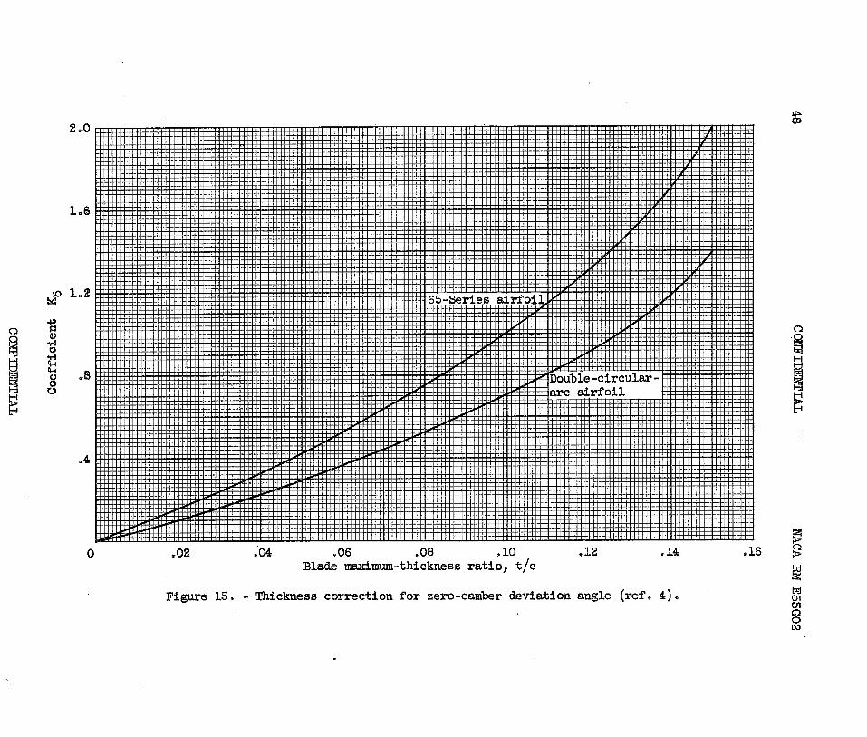
viation angle with incidence angle at reference incidence. Values ofK5.9 (80)10' m, b, and (d8o/di) 2_D for the circular-arc and 65(A10)-
series blade are repeated in figures 15 to 19 for convenience.
Deviation-angle comparisons for the double-circular-arc blade werealso made on the basis of Carter's rule for cascade blades (ref. 30)a
m82-D ° ao.5 (6)
where me is a coefficient that is a function of blade-chord angle
(fig. 20).
CONFIDENTIAL

NACA RM E55GO2 CONFIDENTIAL 15
Carter's rule, which has been used extensively in the design ofcircular-arc blades, was used as the basis for the more elaborate rule ofequation (4). In the calculations, Carter's rule was applied directly tothe compressor reference incidence angles.
The comparisons between measured blade-element reference deviationangle 80C predicted two-dimensional deviation angle s2_D are ex-
pressed in terms of the difference parameter ( sC - S2_D) against relativeinlet Mach number for the three radial positions at hub, tip, and meanradius.
NACA 65(Alo)-series blades. - Curves of compressor deviation angleminus cascade-rule deviation angle (eq. (5)) for the 65-series airfoilfor both rotors and stators are plotted against relative inlet Mach num-ber for the hub, mean, and tip radial positions in figure 21(a). Allvalues of deviation angle correspond to those at compressor reference in-cidence angle. As in the case of the incidence-angle and loss correla-tions, there is considerable scatter of data, particularly in the hub andtip regions. Some of the scatter is believed due to the effects of three-dimensional flows and changes in axial-velocity ratio across the element,but perhaps the most important factors are instrumentation differences anderrors. It is generally recognized that it is difficult to measure com-pressor air angles with an accuracy less than about +1 0 to 1.50 . The cor-relations must therefore be evaluated on an average or trend basis.
The correlation of rotor data in the mean-radius region is fairlygood; axial-velocity ratio varied between about 0.9 to 1.10. On the av-erage, the rotor mean-radius deviation angles are about 0.5 0 less than thecascade values. These results agree with previous experience (refs. 7and 8), which indicated rotor turning angles approximately 1 0 greater(i.e., deviation angles 1 0 less) than the two-dimensional-cascade results.If data points for the rotor tip having axial-velocity ratios less than0.8 are neglected, the average deviation angle is about 0.5 0 less thanthe cascade value. Axial-velocity ratio for the tip-region unflagged datavaried between 0.8 and 1.05. For the hub, on the average, the blade-element deviation angles were about 1.0 0 greater than the correspondingtwo-dimensional values. Hub axial-velocity ratios varied between 1.0 and1.2. As in the two-dimensional cascade (ref. 4), no Mach number effecton deviation angle is indicated over the range of Mach number investigatedfor all three regions.
For the stator mean-radius (Vz,2/Vz)
l - 1.0 to 1.1) and hub-radius
(Vz,2/Vz,1 - 0.85 to 1.05) regions, the average deviation angles are both
about 1.00 lower than the corresponding two-dimensional values. At thestator tip, the average blade-element value is indicated to be about 40less than the two-dimensional value. However, these data all have high
CONFIDENTIAL

16 CONFIDENTIAL NACA RM E55G02
axial-velocity ratios (from 1.1 to 1.5). It is expected that, on thebasis of constant axial velocity, the probable average blade-element de-viation angles at the stator tip might be several degrees closer to thetwo-dimensional values. (Increasing atrial-velocity ratio at essentiallyconstant circulation for the stator tends to decrease deviation angle.)As in the case of the rotor, no essential variation of deviation anglewith Mach number is detected for the stator within the range of Mach num-bers investigated.
Double-circular-arc blade..- Blade-element and two-dimensional-cascade deviation angles eq. (5)) obtained for the double-circular-arcblade are compared in figure 21(b). The scatter of data is generallyless than for the 65(A10 )-series blades, partly because of the generally
more accurate measurements taken in these investigations (all are morerecent than the data of fig. 21(a)).
On the average, at the lower Mach numbers the blade-element deviationangles were about 1.5 0 less than the two-dimensional values at the tip)1.00 greater at the hub, and equal to the two-dimensional values at themean region. Ranges of axial-velocity ratio covered for the data were0.85 to 1.05 at the tip, 0.95 to 1.5 at the hub, and 0.90 to 1.15 at themean radius. A slight increasing trend of variation with inlet Mach num-ber may be indicated at the mean radius and possibly also at the hub.
The double-circular-arc stator data available (solid symbols) are toolimited to permit any reliable conclusions to be drawn. It appears, how-ever, that at the stator mean radius, the blade-element deviation anglesmay be about 0.50 less than the two-dimensional-cascade values. This isessentially the same trend observed for the 65(A10 )-series stators at mean
radius in figure 21(a). Blade-element deviation angles appear to begreater at the tip and smaller at the hub than the two-dimensional values.Ranges of axial-velocity ratio were 1.0 to 1.25 at the tip, 0.95 to 1.27at the mean radius, and 0.9 to 1.30 at the hub.
Blade-element deviation angles and two-dimensional values predictedby Carter's rule (eq. (6)) are compared in figure 22. Inasmuch as Carter'srule results in values of two-dimensional deviation angle between 0.5 0 to1.00 smaller than obtained from the modified rule of equation (5) for therange of blade-element geometries included in the data, the agreement withthe blade-element data remains quite good.
Summary Remarks
From the comparisons of measured and predicted reference deviationangles for the NACA 65(A10 )-series and double-circular-arc blades, it
was found that the rules derived from two-dimensional-cascade data can
CONFIDENTIAL

NACA RM E55GO2 CONFIDENTIAL 17
satisfactorily predict the compressor reference blade-element deviationangle in the rotor and stator mean-radius regions for the blade configu-rations presented. Larger differences between rule and measured valueswere observed in the hub and tip regions. These differences can be at-tributed to the effects of three-dimensional flow, differences in axial-velocity ratio, and measurement inaccuracy. As in the cascade, essen-tially constant deviation angle with Mach number was indicated for theMach number range covered. Additional stator blade-element data, partic-ularly for the double--circular-arc blade, are required to establish thestator correlations more firmly.
APPLICATION TO DESIGN
Design Procedure
The foregoing correlations provide a means of establishing the ref-erence incidence angle and estimating the corresponding deviation angleand total-pressure loss for rotor and stator blade elements of compressordesigns similar to those covered in the analysis. This is accomplishedby establishing deduced curves of compressor blade-element incidence-angle and deviation-angle corrections for the low-speed two-dimensional-cascade rules of reference 4. Reference incidence and deviation anglesfor the compressor blade element are then given by
iC = i2-D + ( iC - i2 ®D) (7)
and
8C = S2-D + (50 - S2
-D) (8)
where i2-D and 82 -D are given by equations (3) and by (5) or (6),respectively. Curves of incidence-angle and deviation-angle correctionsdeduced from the rotor blade-element data of figures 11, 13, 21, and 22are shown as functions of relative inlet Mach number for several radialpositions along the blade height in figures 23 and 24„ The curves infigures 23 and 24 are faired average values of the data spread and,strictly speaking, represent bands of values. In view of the very lim-ited data available, compressor correction curves could not reliably beestablished for the stator deviation and incidence angles.
The establishing of single deduced blade-element loss curves at ref-erence incidence angle is a difficult task because of the scatter of theexperimental data, especially in the rotor tip region. Nevertheless, forcompleteness in order to illustrate the prediction procedures, curves ofaverage total-pressure-loss parameter as a function of diffusion parameter
CONFIDENTIAL
18 CONFIDENTIAL NACA RM E55G02
obtained from the data of figure 14 are shown in figure 25 for rotor andstator. The shaded portion in the figure indicates the possible band ofvalues obtainable at the rotor tip.
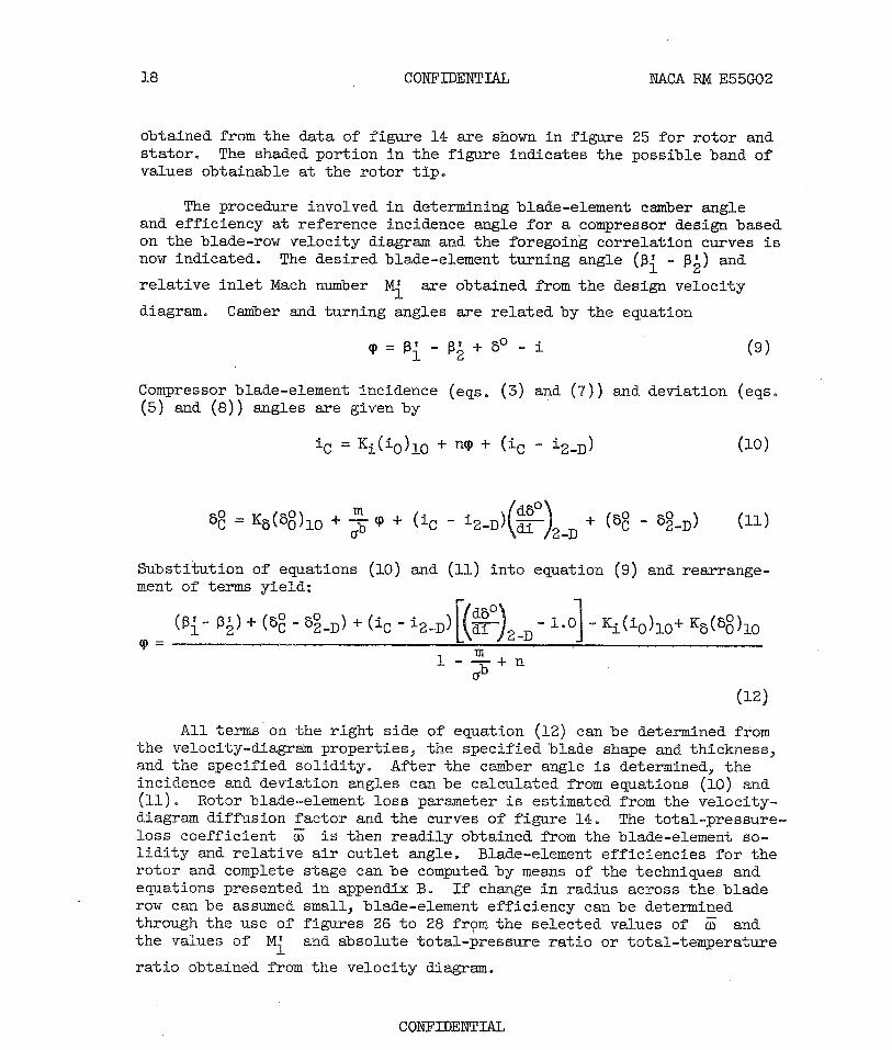
The procedure involved in determining blade-element camber angleand efficiency at reference incidence angle for a compressor design basedon the blade-row velocity diagram and the foregoing correlation curves isnow indicated. The desired blade-element turning angle (pi - 02) and
relative inlet Mach number M1 are obtained from the design velocity
diagram.. Camber and turning angles are related by the equation
(P = Ri- R2 +So -i (9)
Compressor blade-element incidence (eqs. (3) and (7)) and deviation (eqs®(5) and (8)) angles are given by
1C = Ki ('O ) lO + nP + (iC - i2-D ) (10)
0
sC - KS (s0 )10 + b + (1C 12-D ) di 2-D + (sC - s2-D ) (11)
Substitution of equations (10) and (11) into equation (9) and rearrange-ment of terms yield:
0-)(Rl° R^) + ( sC - 82-D ) + (iC - i2-D)[(!dLi)2-D - 1.01 - Ki (i0 ) 10+ K8(50)10m1 - b + ns
(12)
All terms on the right side of equation (12) can be determined fromthe velocity-diagram properties, the specified blade shape and thickness,and the specified solidity. After the camber angle is determined, theincidence and deviation angles can be calculated from equations (10) and(11). Rotor blade-element loss parameter is estimated from the velocity-diagram diffusion factor and the curves of figure 14. The total-pressure-loss coefficient E is then readily obtained from the blade-element so-lidity and relative air outlet angle. Blade-element efficiencies for therotor and complete stage can be computed by means of the techniques andequations presented in appendix B. If change in radius across the bladerow can be assumed small, blade-element efficiency can be determinedthrough the use of figures 26 to 28 from the selected values of E andthe values of Ml and absolute total-pressure ratio or total-temperature
ratio obtained from the velocity diagram.
CONFIDENTIAL
RTACA. RM E55G02 CONFIDENTIAL 19
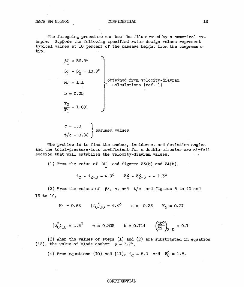
The foregoing procedure can best be illustrated by a numerical ex-ample. Suppose the following specified rotor design values representtypical values at 10 percent of the passage height from the compressortip;
01 = 56.90
R1 - X32 = 10.90
M , - 1.1 obtained from velocity-diagram1 calculations (ref. 1)
D = 0.35
T2Ti = 1.091
a = 1.0assumed values
t/c = 0.06
The problem is to find the camber, incidence, and deviation anglesand the total-pressure-loss coefficient for a double-circular-arc airfoilsection that will establish the velocity-diagram values.
(1)From the value of M1 and figures 23(b) and 24(b),
iC - i2-D = 4.00 50C - 32-D0 = - 1.50
(2)From the values of Rl, Q, and t/c and figures 8 to 10 and
15 to 19,
Ki = 0.62 (iO)lO = 4.40n = -0.22 KS = 0.37
0
(80 10 = 1.60m = 0.305 b = 0®714 = 0.1_D2
(3)When the values of steps (1) and (2) are substituted in equation(12), the value of blade camber tp = 7.70.
(4)From equations (10) and (11), i C = 5.0 and 50C = 1.8.
CONFIDENTIAL

20 CONFIDENTIAL NACA RM E55GO2
(5) For calculation of the total-pressure-loss coefficient, the dif-fusion factor (0.35) and figure 25(a) yield a value of (0.025) for theloss parameter (u; cos 0 1 )/2a, and
02 = Rl - (RlS 2 ) = 56.9 - 10.9 = 46.00
cos P 12 0.6947
Therefore,
_ w cos R2 2cr _ 0.025X22s cos R2 - 0.6947 = 0.072
(6) For a negligible change in radius across the blade element, thefollowing values can be found from figures 26 and 27:
t P
P2 = 0.962 'lad = 0.87 P2 = 1.311 1
The preceding example has been carried out for a typical transonicrotor blade section. A similar procedure can be used for stator-bladesections when adequate blade-element data become available.
Summary Remarks
The foregoing procedures and data apply only to the reference point(i.e., the point of minimum loss) on the general loss-against-incidenGe-angle variation for a given blade element. The reference minimum-lossincidence angle, which was established primarily for purposes of analysis,is not necessarily to be considered as a recommended design point for com-pressor application. The selection of the best incidence angle for a par-ticular blade element in a multistage compressor design is a function ofmany considerations, such as the location of the blade row, the designMach number, and the type and application of the design. However, attransonic inlet Mach number levels, the point of minimum loss may verywell constitute a desired design setting.
At any rate, the establishment of flow angles and blade geometry atthe reference incidence angle can serve as an anchor point for the deter-mination of conditions at other incidence-angle settings. For deviation-angle and loss variations over the complete range of incidence angles,reference can be made to available cascade data. Such low-speed cascadedata exist for the NACA 65(A10 )-series blades (ref. 31).
CONFIDENTIAL

NACA RM E55GO2 CONFIDENTIAL 21
It is recognized that many qualifications and limitations exist inthe use of the foregoing design procedure and correlation data. For bestresults, the application of the deduced variations should be restrictedto the range of blade geometries (camber, solidity, etc.) and flow condi-tions (inlet Mach number, Reynolds number, axial-velocity ratio, etc.)considered in the analysis. In some cases for compressor designs withvery low turning angle, the calculated camber angle may be negative. Forthese cases it is recommended that a zero-camber blade section be chosenand the incidence angle selected to satisfy the turning-angle require-ments. The data used in the analysis were obtained for the most partfrom typical experimental inlet stages with essentially uniform inletflow. Nevertheless, such data have beea used successfully in the designof the latter stages of multistage compressors. It should also be remem-bered that the single curves appearing in the deduced variations repre-sent essentially average or representative values of the experimentaldata spread. Also, in some cases, particularly for the stator, the avail-able data are rather limited to establish reliable correlations. Consid-erable work must yet be done to place the design curves on a firmer andwider basis. The design procedures established and trends of variationdetermined from the data, however, should prove useful in compressorblade-element design.
Lewis Flight Propulsion LaboratoryNational Advisory Committee for Aeronautics
Cleveland, Ohio, August 9, 1955
CONFIDENTIAL

22 CONFIDENTIAL NACA RM E55G02
APPENDIX A
SYMBOLS
The following symbols are used in this report:
A10 65-series mean-line designation
asstagnation velocity of sound, ft/sec
b exponent in deviation-angle relation (eq. (4)), function ofinlet-air angle
CL'o isolated-airfoil lift coefficient
c blade chord, in.
D diffusion factor, 1 -IT t V2
+ V6,ZQVtV9,2' (ref. 14)1 1
i incidence angle, angle between tangent to blade mean camber lineat leading edge and inlet-air direction, deg
Ki,KS coefficients, functions of blade maximum thickness and thicknessdistribution
M Mach number
m coefficient, function of inlet-air angle
mecoefficient, function of blade-chord angle
i-n slope parameter,
i0
CP 2-D
P total pressure, lb/sq ft
p static pressure, lb/sq ft
r radius
s blade spacing, in®
CONFIDENTIAL

23NACA RM E55G02 CONFIDENTIAL
T total temperature
t blade maximum thickness, in.
V velocity, ft/sec
(3 air angle, deg
T ratio of specific heats
TOblade-chord angle, deg
8odeviation angle, angle between tangent to mean camber line atblade trailing edge and air direction, deg
11 efficiency
8 momentum thickness, in®
a solidity, ratio of chord to spacing, c/s
cD camber angle, deg
M angular velocity, radians sec
W total-pressure-loss coefficient
Subscripts:
ad adiabatic
av average
C compressor
GV inlet guide vanes
h hub
id ideal
m mean
min minimum
R rotor
ref reference
CONFIDENTIAL

24 CONFIDENTIAL NACA RM E55G02
S stator
ST stage
t tip
z axial direction
6 tangential direction
0 zero camber
1 before blade row or stage
2 after blade row or stage
2-D low-speed two-dimensional cascade
10 blade maximum thickness-chord ratio of 10 percent
Superscript-
' relative to rotor
CONFIDENTIAL

NACA RM E55GO2 CONFIDENTIAL 25
APPENDIX B
EQUATIONS FOR BLADE-ELEMENT EFFICIENCY
By definition, for a complete stage consisting of inlet guide vanes,rotor, and stator, the adiabatic temperature-rise efficiency of the flowalong a stream surface is given by
P2- l P2 P2 P2- 1
SST = Pl ST _ Pl GV Pl R Pl S
(Bl)
2T2 - 1
T - 1
lST 1R
From the developments of reference 32 (eq. (B8) in the reference), theabsolute total-pressure ratio across a blade row P 2/P1 can be related
to the relative total-pressure ratio across the blade row PZ/P' accord-
ing to the relation
P2 Y
P2 Pl T2 Y'-1
PR121
Tl(B2)
Pl
id
where (PIIPD id is the ideal (no loss) relative total-pressure ratios
The relative total pressure is also referred to as the blade-row recoveryfactors For stationary blade rows, (i.e., inlet guide vanes and stators),(P2/Pl)id is equal to 1.0. For rotors,the ideal relative total-pressure
ratio (eq. (B4) of ref® 14) is given by
^-1
P? = 1 + L21 MT 1 - rl 2
(B3)lid ^2^ 1)in which MT is equal to the ratio of the outlet element wheel speed to
the inlet relative stagnation velocity of sound (mr2fas 1 ), and (r,1/r2)9
CONFIDENTIAL

26 CONFIDENTIAL NACA RM E55GO2
is the ratio of inlet to outlet radius of the streamline across the bladeelement® (For a flow at constant radius (cylindrical flow), (PI/Pt)
is equal to 1.0®) Thus, from equations (Bl) and (B2),
R)a—
Y Yp^ T2 Y-1 p2
_ 1 (
Pl )G IPMP^ T R pl S
_ P1 R,id"ST T2
T- 1
R
For the rotor alone, the blade-element efficiency is given by
Y-1Y
(R)R T2Y'1P2 Tl
- 1
Z-1 1 R, id
T21
Tl R
From equation (B3) of reference 14, the loss coefficient of therotating blade row (based on inlet dynamic pressure) is given by
P2
PT1 - 1
P'2
u^ p = P2 Pl id
1 Pl id Y
1 y'-11 -
1 + 1 21 (Ml)2
where m1 is based on inlet compressible dynamic pressure. For any bladeelement, then, from equation (B6),
71R
(B4)
(B5)
(B6)
CONFIDENTIAL,

NACA RM E55G02 CONFIDENTIAL 27
Y
_t(B7 )
2_ (P2'
1B7Pl
P1 id1
1 + Y21 (Mi)2
The relations presented in equations (B4), (B5), and (B7) indicatethat four quantities are required for the determination of the blade-element efficiency across the rotor or stage: the rotor absolute total-temperature ratio, the relative total-pressure-loss coefficient, (basedon inlet dynamic pressure), the relative inlet Mach number, and theideal relative total-pressure ratio. Thus; the blade-element efficien-cies for a given stage velocity diagram can be calculated if the losscoefficients of the blade elements in the various blade rows can beestimated.
For simplicity in the efficiency-estimation procedure, effects ofchanges in radius across the blade row can be assumed small (i.e.,r1 = r2 ), so that the ideal relative pressure ratio is equal to unity.
Then, equations (B4), (B5), and (B7) become, respectively,
Y
P 4pq T-1 psY
22 2
Pl GV Pl R PZ)^.
T' ST T2
- 1Tl R
Y-1
Y Y
P 4 T Y-12 2 - 1
Pl R T1 R
^R - m- 1T,Ja-1
and
- 1
(B8)
(B9)
CONFIDENTIAL

28 CONFIDENTIAL NACA RM E55G02
Y
P 2' 1r-1
12 v (B10)
P't - ^ u^l 1 -
1 1 + Y21 (Ml)2
For purposes of rapid calculation and preliminary estimates, theefficiency relations are expressed in chart form in figures 26 to 28.The relation among relative recovery factor, blade-element loss coeffi-cient, and inlet Mach number (eq. (B10)) is presented in figure 26. Achart for determining rotor blade-element efficiency from relative recov-ery factor and absolute total-temperature ratio (eq. (B9)) is given infigure 27. Lines of constant rotor absolute total-pressure ratio arealso included in the figure. Figure 28 presents the ratio of stage effi-ciency to rotor efficiency for various stator or guide-vane recoveryfactors. The ratio of stage efficiency to rotor efficiency is obtainedfrom equation (Bl) in terms of rotor absolute total-pressure ratio as
Y'-1YP2P2 P2
12ST P R Pl JGV Pl S (Bll)TIRY-1
p2 Y^P
Vl/R- 1
The charts are used as follows: For known or estimated values ofrotor total-pressure-loss coefficient ctrl and relative inlet Mach number
of the element M1',, the corresponding value of relative recovery factor
P2/P1 is determined from figure 26. From the value of rotor-element
absolute total-temperature ratio T 2/T1 (obtained from calculations of
the design velocity diagram) and the value of (P2/Pi) obtained from fig-
ure 26, the rotor element efficiency is determined from figure 27. Rotorabsolute total-pressure ratio can also be determined from the dashedlines in figure 27.
If inlet guide vanes and stators are present, the respective recov-ery factors of each blade row are first obtained from figure 26. Theproduct of the two recovery factors is then calculated and used in con-junction with the rotor absolute total-pressure ratio in figure 28 todetermine the ratio of stage efficiency to rotor efficiency. A simplemultiplication then yields the magnitude of the stage efficiency alongthe element stream surface.
CONFIDENTIAL

NACA RM E55G02 CONFIDENTIAL 29
The charts can also be used to determine gross or mass-averagedefficiencies through the use of over-all loss terms. Furthermore, thecharts can be used for the rapid determination of relative total-pressure-loss coefficient from known values of efficiency, pressure ratio, and in-let Mach number on an element or gross basis.
REFERENCES
1. Giamati, Charles C., Jr., and Finger, Harold B.: Aerodynamic Designof Axial-Flow Compressors. VIII - Design Velocity Distribution inMeridional Plane. NACA RM
2. Robbins, William H., and Dugan, James F., Jr.: Aerodynamic Design ofAxial-Flow Compressors. X - Prediction of Off-Design Performance ofMultistage Compressors. NACA RM E55DO5.
3. Roudebush, William H.: Aerodynamic Design of Axial-Flow Compressors.IV - Potential Flow in Two-bimensional Cascades. NACA RM E54H26.
4. Lieblein, Seymour: Aerodynamic Design of Axial-Flow Compressors.VI - Experimental Flow in Two-Dimensional Cascades. NACA RM
5. Bowen, John T., Sabersky, Rolf H., and Rannie, W. Duncan: Theoreticaland Experimental Investigations of Axial Flow Compressors, Pt. 2.Mech. Eng. Lab.; C.I.T., July 1949. (Navy Contract N6-ORI-102, TaskOrder IV.)
6.. Alsworth, Charles C., and Iura, Toru: Theoretical and ExperimentalInvestigations of Axial Flow Compressors. Pt. 3 - Progreso Reporton Loss Measurements in Vortex Blading, Mech. Eng. Lab., C.I.T.,July 1951. (Navy Contract N6-ORI-102, Task Order IV.)
7. Schulze, Wallace M., Erwin, John R., and Ashby, George C., Jr., NACA65-Series Compressor Rotor Performance with Varying Annulus-AreaRatio, Solidity, Blade Angle, and Reynolds Number and Comparisonwith Cascade Results. NACA RM L52L17, 1953.
8e Ashby, George C., Jr.: Comparison of Low-Speed Rotor and Cascade Per-formance for Medium-Camber NACA 65-(C
Z0 A lO)10 Compressor-Blade Sec-
tions overa Wide Range of Rotor Blade-Setting Angles at Soliditiesof 1.0 and 0.5. NACA RM L54I13, 1954.
9. Andrews, S. J., and Ogden, H.: A Detailed Experimental Comparison ofBlades Designed for Free Vortex Flow and Equivalent Untwisted Con-stant Section Blades. Rep. No. R.123, British N.G.T.E., Aug. 1952.
CONFIDENTIAL

30 CONFIDENTIAL NACA RM E55GO2
10. Bullock, Robert 0.,dynamic Design ofSystem. NACA RM
Johnsen, Irving A., and Lieblein, Seymour: Aero-Axial-Flow Compressors. III - Compressor Design
11. Lieblein, Seymour: Review of High-Performance Axial-Flow-CompressorBlade-Element Theory. NACA RM E53L22, 1954.
12. Savage, Melvyn, Erwin, John R., and Whitney, Robert P.: Investigationof an Axial-Flow Compressor Rotor Having NACA High-Speed Blade Sec-tions (A2I8b Series) at Mean Radius Relative Inlet Mach Numbers up
to 1.13. NACA RM L53GO21 1953.
13. Schwenk, Francis C., Lieblein, Seymour, and Lewis, George W., Jr.:Experimental Investigation of an Axial-Flow Compressor Inlet StageOperating at Transonic Relative Inlet Mach Numbers. III - Blade-Row Performance of Stage with Transonic Rotor and Subsonic Statorat Corrected Tip Speeds of 800 and 1000 Feet Per Second. NACA RME53G17 1 1953.
14. Lieblein, Seymour, Schwenk, Francis C., and Broderick, Robert L.:Diffusion Factor for Estimating Losses and Limiting Blade Loadingsin Axial-Flow-Compressor Blade Elements. NACA RM E53D01, 1953.
15. Savage, Melvyn: Analysis of Aerodynamic Blade-Loading-Limit Param-eters for NACA 65-(CZ
0 AlO )10 Compressor-Blade Sections at Low Speeds.
NACA RM L54LO2a, 1955.
16.Moses, Jason J., and Serovy, George K.: Effect of Blade-SurfaceFinish on Performance of a Single-Stage Axial-Flow Compressor.NACA RM E51C09, 1951.
17. Moses, J. J., and Serovy, G. K.: Some Effects of Blade Trailing-EdgeE ' Thickness on Performance of a Single-Stage Axial-Flow Compressor.
NACA RM E51F28, 1951.
18. Thurston, Sidney, and Brunk, Ralph E.: Performance of a Cascade inan Annular Vortex-Generating Tunnel over a Range of Reynolds Num-bers. NACA RM E51G30, 1951.
19.Wallner, Lewis E., and Fleming, William A.: Reynolds Number Effecton Axial-Flow Compressor Performance. NACA RM E9G11, 1949.
20.Muhlemann, E. (John Perl, trans.): Experimental Investigations onan Axial Blower Stage. Lockheed Aircraft Corp., Burbank (Calif.).
21.Roudebush, William H., and Lieblein, Seymour: Aerodynamic Design ofAxial-Flow Compressors. V - Viscous Flow in Two-Dimensional Cas-cades. NACA RM
CONFIDENTIAL

NACA RM E55GO2 CONFIDENTIAL 31
22. Dugan, Paul D., Mahoney, John J., and Benser, William A.: Effect ofMach Number on Performance of an Axial-Flow Compressor Rotor-BladeRow. NACA RM E8D29, 1948.
23. Voit, Charles H., Guentert, Donald C., and Dugan, James F.: Effectof Mach Numbers on Over-All Performance of Single-Stage Axial-FlowCompressor Designed for High Pressure Ratio. NACA RM E5OD26, 1950.
24. Robbins, William H., and Glaser, Frederick W.: Investigation of anAxial-Flow Compressor Rotor with Circular-Arc Blades Operating upto a Rotor-Inlet Relative Mach Number of 1.22. NACA RM E53D24,1953.
25. Herzig, Howard Z., and Hansen, Arthur G.: Aerodynamic Design ofAxial-Flow Compressors. XIV - Three-Dimensional Compressor FlowTheory and Real Flow Effects. NACA RM E55DO4a.
26. Hansen, Arthur G., and Herzig, Howard Z.: Aerodynamic Design ofAxial-Flow Compressors. XV - Secondary Flows and Three-DimensionalBoundary-Layer Effects. NACA RM E55D06.
27. Lieblein, Seymour, and Ackley, Richard H.: Secondary Flows in Annu-lar Cascades and Effects on Flow in Inlet Guide Vanes. NACA RME51G27, 1951.
28. Erwin, John R., and Emery, James C.: Effect of Tunnel Configurationand Testing Technique on Cascade Performance. NACA Rep. 1016, 1951.(Supersedes NACA TN 2028.)
29. Mankuta, Harry, and Guentert, Donald C.: Some Effects of Solidity onTurning Through Constant-Thickness Circular-Arc Guide Vanes in AxialAnnular Flow. NACA RM E51E07, 1951.
30. Carter, A. D. S., and Hughes, Hazel P.: A Theoretical Investigationinto the Effect of Profile Shape on the Performance of Airfoilsin Cascade. R. & M. No. 2384, British A.R.C., Mar. 1946.
31. Felix, A. Richard: Summary of 65-Series Compressor-Blade Low-SpeedCascade Data by Use of the Carpet-Plotting Technique. NACA RML54H18a, 1954.
32. Howell, A. R.: Design of Axial Flow Compressors. War EmergencyIssue No. 12 pub. by Inst. Mech. Eng. (London), 1945. (Reprintedin U. S. by A.S.M.E., Jan. 1947, pp. 452-462.)
33. Jackson, Robert J.: Effects on the Weight-Flow Range and Efficiencyof a Typical Axial-Flow Compressor Inlet Stage That Result from theUse of a Decreased Blade Camber or Decreased Guide-Vane Turning.NACA RM E52GO2, 1952.
CONFIDENTIAL

32 CONFIDENTIAL NACA RM E55GO2
34. Jackson, Robert J.: Analysis of Performance of Four Symmetrical-Diagram-Type Subsonic Inlet-Stage Axial-Flow Compressors. NACARM E53KO3, 1954.
35. Mahoney, John J., Dugan, Paul D., Budinger, Raymond E., and Goelzer,H. Fred : Investigation of Blade-Row Flow Distributions in Axial-Flow-Compressor Stage Consisting of Guide Vanes and Rotor-BladeRow. NACA RM E50G12, 1950.
36. Standahar, Raymond M., and Serovy, George K.: Some Effects of Chang-ing Solidity by Varying the Number of Blades on Performance of anAxial-Flow Compressor Stage. NACA RM E52A31, 1952.
37. Serovy, George K., Robbins, William H., and Glazer, Frederick W.:Experimental Investigation of a 0.4 Hub-Tip Diameter Ratio Axial-Flow Compressor Inlet Stage at Transonic Inlet Relative Mach Num-bers. I - Rotor Design and Over-All Performance at Tip Speedsfrom 60 to 100 Percent of Design. NACA RM E53I11, 1953.
38. Tysl, Edward R., Schwenk, Francis C., and Watkins, Thomas B.: Experi-mental Investigation of a Transonic Compressor Rotor with a 1.5-InchChord Length and an Aspect Ratio of 3.0. I - Design, Over-All Per-formance, and Rotating-Stall Characteristics. NACA RM E54L31, 1955.
39. Lewis, George W., Jr., Schwenk, Francis C., and Serovy, George K.:Experimental Investigation of a Transonic Axial-Flow-CompressorRotor with Double-Circular-Arc Airfoil Blade Sections. I - Design,Over-All Performance, and Stall Characteristics. NACA RM E53L21a,1954.
40. Sandercock, Donald M., Lieblein, Seymour, and Schwenk, Francis C.:Experimental Investigation of an Axial-Flow Compressor Inlet StageOperating at Transonic Relative Inlet Mach Numbers. IV - Stage andBlade-Row Performance of Stage with Axial-Discharge Stators. NACARM E54C26, 1954.
CONFIDENTIAL

TABLE I. - DETAILS OF SINGLE-STAGE ROTORS AND STATORS
Blade Description Outer Hub- Rotor Inlet Mach Camber angle, Chord, Solidity, Blade chord Blade maximum Refer-row "diameter, tip tip speed, number, cp, deg c, in. a angle, T, thickness enoes
in. ratio ft/sec Mil chord ratio,t/c
Hub Tip Hub Tip Hub Tip Hub Tip Hub Tip
65-Series blade section
1 Rotor 14 0.5 552,828,994 0.30-0.75 19.9 15.3 1.31 1.31 1.010 0.590 30.8 56.4 10 10 331104,1214
2 Stator 14 .55 552,1104 .26- .73 30.1 30.1 1.31 1.31 .996 .620 19.5 45.9 10 10 343 Rotor 30 .80 504,672,.840 .36- .70 30.1 30.1 2.90 2.90 1.08 .906 28.8 45.9 10 10 354 Rotor 14 .50 1104,1214 .60- .80 30.1 30.1 1.31 1.31 1.010 .590 21.1 56.0 10 10 345 Rotor 14 .50 557,743 .39- .72 30.1 30.1 1.31 1.31 .962 .608 15.2 32.0 10 10 346 Stator 14 .52 391,557,743 .22- .66 30.1 30.1 1.31 1.31 .993 .631 16.2 32.2 10 10 347 Rotor 14 .50 546 .35- .56 40.0 23.9 1.31 1.31 .955 .600 21.0 58.0 10 10 338 Rotor 14 .50 552,1104,828 .30- .86 40.0 23.9 1.31 1.31 .955 .600 21.0 58.0 10 10 339 Rotor 14 .50 552,828,1104 .30- .76 40.0 23.9 1.31 1.31 .955 .600 21.0 58.0 10 10 33
121410 Stator 14 .53 412,617,823 .25- .74 30.1 30.1 1.31 1.31 .970 .587 15.1 39.6 10 10 3411 Rotor 14 .80 669,753,8.36 .52- .75 45.2 34.1 1.35 1.35 .823 .692 21.4 35.4 6 6 3612 Rotor 14 .80 669,753,836 .49- .75 45.2 34.1 1.35 1.35 1.12 .943 21.4 35.4 6 6 3613 Rotor 14 .80 669,753,836 .49- .75 45.2 34.1 1.35 1.35 1.69 1.35 21.4 35.4 6 6 3614 Rotor 14 .80 600,736,874 .50- .92 30.3 19.4 1.46 1.82 1.20 1.20 42.5 48.8 10 8 17
Circular-arc blade section
15 Rotor 14 0.4 600,800,1000 0.33-1.06 40.3 11.4 2.00 2.00 1:778 0.963 12.1 46.7 8 5 3716 Rotor 18.0 .5 600,700,800 .38-1.07 28.3 7 1.5 1.5 1.63 1.03 23.6 46.3 10 6 38
900,100017 Rotor 14 .5 600,800,900 .37-1.17 29.4 13.7 2.09 2.32 1.28 1.04 23.0 44.1 8 5 39
100018 Rotor 14 .5 800,900 .55-1.12 29.4 13.7 2.09 2.32 .85 .66 23.0 44.1 8 5 3919 Rotor 14 .5 800,900,1000 .50-1.22 23.1 4.3 1.50 1.50 1.40 .825 17.4 51.3 10 5 24
112020 Rotor 14 .5 800,900,1000 .4 - .82 23.1 4.3 1.50 1.50 1.40 .825 17.4 51.3 10 5 24
112021 Stator 17.36 .62 600,800,900 .41- .63 52.0 52.0 3.25 3.25 1.64 1.07 10.0 10.0 7 7 4022 Stator 17.36 .60 800,1000 .53- .66 20.6 20.0 2.66 3.23 1.45 1.08 34.0 28.0 8 6 13
WEn01
Q
II
d
r
WU1

CA
Figure 1. - Compressor blade elements shown along conical surface of revolutionabout compressor axis.
W
t^
Compressor
Col
/I CD-4360

NACA RM E55G02 CONFIDENTIAL 35
Chord, C
Wake
Chord angle,yo
Spacing, sDeviation angle, So
\ V Outlet velocity, VZ
Mean camber line
Outlet-airangle, p^
Incidenceangle, i-,
Inletvelocity,V1
Inlet-air/ angle, Rl
- Axis
Camber angle, Cp
Pi - RZ = air turning angle
Figure 2m- Blade-element properties.
CONFIDENTIAL

Lentit are
65me
w
ca
H
0
N8
Figure 3. - Equivalent circular--arc mean line for NACA 65(AlC)-series blades bicncn

32
28
24
bo20
wm
16
U
L3Ne^
12
W
8
4
0
60
56
52
48
4
40
36
32
284 8 12 16 20 24
w
6-
a^
U
Nr-1
o'w
HACA RM E55CO2 CONFIDENTIAL 37
Design (isolated-airfoil) lift coefficient, CL o9
Figure 4m - Equivalent camber angles for NACA 65(c 1010) mean camber line
as equivalent circular arc (fig. 3).
C0NFIDENTIAL

A
FaOYUCdw0OMWyWwrlA
i^
38 CONFIDENTIAL NACA RM E55GO2
0 10CO
bme
6
°aY
ri9NA
2
m0Or+l 3r _
Fa YO'C0 mf^ rlU Ua.w^wri wca o0 UOE
0 1.
4-Ymu
Yrl N0a 1.0
^ NI
ri
k
FaeA8C ,
.0U
YNri
rl
N
Y14
df^
tll
ro
—N
N
0
to
0CF.01 1 7^ I I I I I J r I
-4 0 4 8 12 -4 O 4 8Incidence angle, 1, deg
Figure 5. - Examples of typical variation of blade-element performance parameters withincidence angle. Transonic rotor with double-circular-arc blade sections at tipspeed of 800 feet per second; data for blade row 17 (table I) at tip position(ref. 39).
CONFIDENTIAL

1^1cn
Nw-!Vri4-i4i
CJ
13
mm
H
ca Referenceincidenceangle,
0
Incidence angle, i, deg
(a) miniumm lass
(b) Mid-range.
Figure 6. - Definitions of reference incidence angle.
CACD

Thin-pl orif ice -
Uter, screens, and honeyconb
1-1 Figure 7. - Schematic diagram of single-stage compressor test installation.

NACA RM E55GO2 CONFIDENTIAL
41
1®2
1.0
Double
a) ®6Url4-i4-iNOU
44
.2
0 .02 .04 .06 008 ®10 .12Blade maximum-thickness ratio, t/c
Figure 8s - Thickness correction for zero-camber reference incidence angle(ref. 4)
1
®8
CONFIDENTIAL

bn
0
0
ai
Cd
U
Nz9SriU
rl
NU
N$aN
UFi
f-1N
U1
OHNN
42 CCEFIDEMIAL NACA RM E55G02
Inlet-air angle, (31, deg
Figure 9. - Zero-camber reference incidence angle for NACA 65-series and truecircular-arc blades of 10-percent thickness ratio (ref. 4).
CONF'IDER'I'IA.I,

Q0
0-0.4
_^5
-.4
0
111. JL ....
solidity, cr,MI
: --#MO.
I 1 1 14 1 1 1
4=11
TfF
Cn
0
0 1
--Al.--Al. 00
P' -,20r-iCO
-.1
0
10 20 30 40 50 60 70
Inlet-air angle, 0 1 , deg
Figure 10. - Reference-incidence-angle slope parameter for NACA 65-series blades as equiva-lent circular arcs and for true circular-arc blades (ref. 4).

44 CONFIDENTIAL NACA RM E55G02
to
raN
rt
a
to
qa
9
.Ii
9
u
r9
°
m
00
Mean Blade row®® (table I)
0 10 ® 2
® 0 O o ° o ® 3vs
LA 5® 0 6
-4 0 7® 0 8
Q 910
v 14

Is
a^
w
e^
mCO0a
to
as-w
H
WCACn
0ro
ca
Hd.
0
4H
r
Incidence angle, i, deg
Figure 12. - Typical variation of loss with incidence angle for rotorblade element near tip and in two-dimensional cascade for same bladegeometry and inlet Mach number.
4

46
COEFIDENTIAL
NACA. RYA E55GO2
12
8
to
A 4
Ne
a
A 0to
mU
-4
miU
14
EQ
Urf
U
U
c0
to
dUF(
19
HubBlade row(table I)
v 15p p O 16
o v 17v 18
ov ° a 19
® v 20_ F 21
IP
--^® 22
— High-speed
p cascade (ref. 4)
ter.
9rf
BTUf.'U
0
0U
v4 v v
Tip ' p
0
V-4
.3 .4 .5 a6 ,7 a8 .9 100 1a1 1.2
Relative inlet Mach'number, Mi
Figure 13. - Variation of compressor reference incidence angle minus two-dimensional.-cascade-rule incidence angle with relative inlet Mach number for double-circular-arc blade section.
C OBFI DENTIAL

NAACA RIB E55G02 CCNFIDElqTIAL
47
.o=
0
.10
05
0
-cum .15m pO NU
tiy .1001
Famo .05
a^u02mM
'D 0a
m-P 0 .05
H
Rotor hub4 Blade row
a v (table I)0
1
Stator hub
0
.05Stator mean
0
.05Stator tip
Diffusion factor, D
Figure 14. - Variation of total-pressure loss parameter with diffusion factor at reference incidenceangle for NACA 65(A10 )-series and double-circular-arc blade sections.
CONFIDEN'T'IAL
OD2A
1.6
t1.2
c^ o
c^
°80
o
.4
-circular-rfoil
0 .02 .04 .06 .08 .10 .12 .14
Blade maximum-thickness ratio, t/c
Figure 15. - Thickness correction for zero-camber deviation angle (ref. 4).
0.16 n
ts1v,u,
N

O
d
t4EncnCp0N
C]
boaDId
Or-i
00Cou
mrlbQ
O
Cd
N
N
UB
O
0N
0 10 20 30 40 50 60 70Inlet-air angle, al, deg
Figure 16. - Zero-camber deviation angle for NACA 65-series and true circular-arc bladesof 10-percent maximum-thickness ratio (ref. 4).
co

tmjM
0
CA0
®4
.5-arc
1r0
-Series mean line,
10 20 30 40 50 60 70Inlet-air angle, Ri,.deg
Figure 17. - Coefficient of m in deviation rule (ref. 4) .
0
4
c^
d
r
N

c^ a^
Ua^{
4r4-IUO0
c^
1. 1 .)H
cncn
0 10 20 30 40 50 60 70Inlet-air angle, 01, deg
Figure 18. m Solidity exponent b in deviation rule (ref. 4). cnN

.z 4 6 .8 1.0 1.2 1.4 1.6 1.8Solidity, x
Figure 19. - Deviation-angle slope (d8 o/di)2-D at reference incidence angle (ref. 4).
1.0
0
WU1
AN .8
1-IrdOCord
N6
mrd
O q
H OU
.4
D(DN ^
cd
a)P,
rO .2CO
N
O
N

v .32
vi
e^
4-+
X26
.24
.200
0
H
.44
840
.36
FP
WCA
iv
k:
H
N
10 20 30 40 50 60 70Blade-chord angle, r , deg
Figure 20. - Variation of mC for circular-arc compressor cascades (ref. 31). MCA

Blade row (table I) V ,2/Vz,1
w 12
Flags to right 1.2O 3 Flags to left <.8
e 4O 59 60 7p 8® 9
100 14
Hub
p v0
o pV
v
O + D' 0
8
^ 4
aoN
I C
to
w
-4
q0rl "
Tipb
p
o p
0 O 0
`^ ® ® vO v
lid
8
! 4
0
-4
-8
54
CONFIDENTIAL
HACA RM E55G02
.2 .3 .4 .5 .6 .7 .8 .9 1.0'Relative inlet Mach number, g1
(a) 65(A10) -Series blade section.
Figure 21. - Variation of compressor deviation angle minus two-dimensional-cascade deviation angle at compressor reference incidence angle withrelative inlet Inch number.
CONFIDENTIAL

4
04
CdCd
y -4
4bom
mmU ^^
0
N ^.I6o
-40U
4
s+0m 0EDa)HO00
-4
NACA RM E55GO2 CONFIDENTIAL 55
Blade row(table I)
V 15O 16
Hub 0 17° v 18
v P Q ® a 19yr c^ v v 20
v ® I 21s 22
FlagsVz^2/ Vz'1 > 1.2'® ^/
.4 .5 .6 .7 .8 99 1.0 1.1 1,2Relative inlet Mach number, "Z
(b) Circular-arc blade section.
Figure 21. - Concluded. Variation of compressor deviation angle minus two-dimensional-cascade deviation angle at compressor reference incidenceangle with relative inlet Mach number..
CONFIDENTIAL

56 CONFIDENTIAL NACA RM E55G02
4:m
A9
°0 0
0N
-4
97O
aiy
4
9
m
0vm
—4
.4 .5 a6 ,7 .8 a9 1®0 1.1 1.2Relative inlet Mach number, Mil
Figure 22. - Variation of compressor deviation angle minus deviation anglepredicted by Carter ' s rule at reference incidence angle with relativeMach number for double-circular -arc blade section.
014;6
a0
m
a^
0mma^
0v
CONFIDENTIAL

t of blade heiommressor tip
WCJl
CJ1
ON
4
UN
u bn 0m N
P,
^S A
-4 r#
- 4
0 8Y ^
v 4'
N
o oN 'FiNNH
U-4 2
(a) NACA 65(A10)-series blades.
0
d
.3 .4 .5 .6 .7 .8 .9 1.0 1.1 1.2Relative inlet Mach number, Mi
(b) Double-circulex-arc blades.
Figure 23. - Deduced variation of average rotor reference incidence angle minus low-speed two-dimensional-cascade-rule reference incidence angle with inlet Mach number.

(a) NACA 65 (A, ,) -series blades.
- .2 .3 .4 .5 .6 .7 .8 .9 1.0 1.1 1.2
Relative i n l e t Mach number, M i
(b) Double -circular-arc blades.
Figure 24. - Deduced variation of average rotor devf ation angle minus low -speed two-dimensional- s F
cascade-rule deviation angle a t compressor referelice incidence angle with re la t ive i n l e t Mach number. %!
M Ui
E n,

4-FH11P
10
THd 30, 50 2 70, 9,
m I bo NU
13
w
mm0
mmm
00H
)5
.Q(a) Rotor
NACA RM E55GO2 CONFIDENTIAL, 59
-Nm
V .l .G .J .'t .J .O •!Diffusion factor, D
(b) Stator.
Figure 25. - Deduced variation of total-pressure-loss parameter with diffusion factorat reference incidence angle for NACA 65(A lQ)-series and double-circular-arc blades.
CONFIDENTIAL

1.00
98
.96
1 .94w
a
4 .92m
mm0HP,
.9004^0
m
va ,gg
.86
.84
82
60 CONFIDENTIAL NACA RM E55GO2
Relative inletMach number,
M'1
Total-pressure-loss coefficient, w
Figure 26. - Variation of rotor relative.total-pressure ratio with total-pressure-loss coefficient and inlet Mach number.
p1 - Pi_ 1
W 11 -
Y
1 + Y21
(M1)21 Y-1
CONFIDENTIAL

1.1
a
PP.
0
CdCd
F,
dc^
mmd'uaCdm00
ma,-i+dCd
a^x
Absolute total-temperature ratio, T2/Tl
NACA RM E55G02 CONFIDENTIAL 61
Rotor adiabatic efficiency
Rad,R
Figure 27. - Variation of relative total-pressure ratio with absolutetotal-temperature ratio and efficiency for rotor.
2-1
P'
PiCT1 - 1.0
T1adT2T - 1.01
CONFIDENTIAL

62 CONFIDENTIAL NACA RM E55GO2
Stator recoveryfactor,
(P2/P1)S1.
aHCw
UNUri4-tQ-IN
0O0OP,
O
Uf7NriUMMN
N
MN
WOOi^
m
34
:19
1.0 1.2 1.4 1.6 1.8 2.0Rotor total-pressure ratio, (P2/P1)R
Figure 28. - Variation of ratio of stage to rotor efficiency withrotor absolute total-pressure ratio as function of stator recov-ery factor.
r nTTW Tn aTfi" T d T.

NACA RM E55G02
AERODYNAMIC DESIGN OF AXIAL-FLOW COMPRESSORS
VII - BLADE-ELEMENT FLOW IN ANNULAR CASCADES
/ \^4-1: J
William H. RobbinsAeronautical Research Scientist
Compressors and Turbines
Robert J. JacksonAeronautical Research Scientist
Compressors and Turbines
Seymour LiebleinAeronautical Research Scientist
Compressors . and Turbines
Approved: ,
William A. BenserAeronautical Research Scientist
Compressors and Turbines
'Robert 0. BullockAeronautical Research Scientist
Compressors and Turbines
Oscar W. ScheyChief, Compressor and Turbine
Research Division
cwk - 8/9/55
NACA-CLEVELANDRestriction/Classification Cancelled
Restriction/Classification Cancelled

NACA RM E55G02
Cascades
1.4.5
Cascades, Theory
1.4.5.1
Cascades, Experiment
1.4.5.2
Compressor Flow Theory and Experiment
3.6.1
Compressors - Axial Flow 3.6.1.1
Robbins, William H., Jackson, Robert J., and Lieblein, Seymour
AERODYNAMIC DESIGN OF AXIAL-FLOW COMPRESSORSVII - BLADE-ELEMENT FLOW IN ANNULAR CASCADES
Abstract
Annular blade-element data obtained primarily from single-stage com-pressor installations are correlated over a range of inlet Mach numbersand cascade geometry. The correlation curves are presented in such amanner that they are related directly to the low-speed two-dimensional-cascade data of part VI of this series. Thus, the data serve as both anextension and a verification of the two-dimensional-cascade data. Inaddition, the correlation results are applied to compressor design.
CON
Restriction/Classification Cancelled
Restriction/Classification Cancelled


![Low-Speed Aerodynamic Characteristics of NACA 0012 …naca.central.cranfield.ac.uk/reports/arc/rm/3726.pdf · · 2013-12-05Low-Speed Aerodynamic Characteristics of NACA 0012 Aerofoi]](https://static.fdocuments.us/doc/165x107/5aa786827f8b9a50528c845f/low-speed-aerodynamic-characteristics-of-naca-0012-naca-aerodynamic-characteristics.jpg)


