
NACA RM No. SEBHO3 - Digital Library/67531/metadc... · NACA RM No. SEBHO3 3 1176 01437 9664 1 (...
15
Transcript of NACA RM No. SEBHO3 - Digital Library/67531/metadc... · NACA RM No. SEBHO3 3 1176 01437 9664 1 (...

!I
I :
j
i
I’r
1
b ;
t
I! ;
ip i litt
i
i, $1
p
NACA RM No. SEBHO3 3 1176 01437 9664
1 (
NATIONAL ADVISORY COMMITTEX FOR AERONAUTICS . . . - _. m ,H fifJiJ@~Iz---: ~.,
for the
Air Materiel Command, U. S. Air Force
CALIBRATIONOFAIR-FLOVWFOR
J33 COMEU$%OR ZtNVXSTIWION
By Karl Kovach and Joseph R. W ithee, Jr.
Flow-metering devices used by the NACA and by the manufacturer of the 533 turbojet engine were calibrated together to determ ine whether an observed discrepancy in weight flow of approximately 4 percent for the two separate investigations m ight be due to the different devices used to meter air flow. A commercial adjustable orifice and a square-edge flat-plate orifice used by the KACA and a flow nozzle used by the manufacturer were calibrated against surveys across the throat of the nozkle. It was determ ined that over a range of weight flows from 18 to 45 pounds per second the average weight flows measured by the metering device used for the compressor test would be 0.70 percent lower than those measured by the metering device used in the engine tests and the probable variation about this mean would be f0.39 percent. The very close agreement of the metering devices shows that the greater part of the discrepancy in weight flow is attributable to the effect of inlet pressure.
INTRODUCTION
At the request of the Air Materiel C ommand, U. S. Air Force, an investigation is being conducted at the NACA Cleveland labora- tory to determ ine the performance characteristics of a series of 533 turboJet-engine comprsssors. Engine tests by the manufacturer and component tests by the NACA with the 17-blade impeller of the 533-A-23 compressor (reference 1) produced different values of weight 'flow, which-may‘have been caused by errors-in flow metering or by the fact that the two investigations had to be conducted at different inlet pressures. In order to determ ine the magnitude of

NACA RM No. SE8HO3 2
the differences resulting from the air-flow metering devices, the: commercial adjustable orifice and the submerged, flat-plate, square- edge oi-iffiii; 'used by-the XACA, and a flow nozzle used by the manu-. facturer were calibrated against weight flows from surp~ys across the nozzle throat. 'The weight flows ranged from 18 to 45 pounds per second.
Two separate systems, which were actually the two alternate inlet systems available for the J33 turbojet engine compressors, were used in the present study. One system contained a carrnnercial adjustable orifice and the other a submerged, flat-plate, square- edge orifice. The flow nozzle could be connected at the inlet of either system and air was drawn through these systems by the labor- atory exhaust facilities.' All temperaturcee were read on a cali- brated potentiometer in conjunction with a spotlight galvanometer.
Flat-plate orifice. - The 18.394-inch-diameter orifice was mounted in a 40.88-inch-diameter pipe as shown in figure 1; two l/8-inch-diameter corner static-pressure taps were located 1; inches upstream of the orifice, and two were located li inches downstream of the orifice. One upstream and one downstream tap were connected to a differential water manometer and the upstream tap was also con- nected to an absolute-reading mercury manometer. The other two taps were connected to a separate differential water manometer as a check. Two total-temperature thermocouples were located 1 pipe diameter upstream of the orifice plate on diametrically opposite sides of the pipe and extended into the pipe one-third the pipe diameter.
Adjustable orifice. - The ZO-inch adjustable orifice had an upstream and downstream static-pressure tap as an integral part of the flow-meter body. The pressure drop across the orifice was
' measured on a differential water manometer and the upstream 'tap was connected to an absolute-reading mercury manometer. A total- temperature thermocouple was located approx-imately 3 pipe diameters upstream of the orifice and extended into the pipe one-half the pipe diameter.
Flow nozzle. - The instrume,ntation of the flow nozzle is shown in figure 2. Mounted at the upstream face of.the nozzle was a wooden panel to simulate the nozzle installation in engine test8 by the manufacturer. The up&ream instrumentation consisting of
, . . , . .--,.. , .,

NACA RM No. SESHO3 3
four static-pressure taps and four total-temperature thermocouples 1_ was mounted on the wooden panel. Four static-pressure taps were
loc%ed~90°'~apart in the throat of the nozzle as shown in figure 3. All of the static-pressure taps were connected to individual water manometers.
A movable total-pressure probe (fig. 4) was located at the throat of the nozzle in the plane of the static-pressure taps. This probe could be accurately positioned at each of the 36 meaeuring stations across the nozzle throat and could be moved to any one'of four positions at 45O intervals (fig. 3).
The probe was connected to one of the static-pressure taps in the nozzle throat through a differential water manometer. A cali- brated microbarograph was used to measure the total pressure upstream of the nozzle. A fixed total-pressure probe in the throat of the nozzle indicated variations in flow during each survey.
All pressures were corrected for changes in density of the measuring fluids by the method recommended in reference 2. The precision of the measurements Is estimated to be within the follow- ing limits:
Temperature, 9. ...................... f0.5 Pressure, inches mercury absolute .............. f0.04 Pressure, inches water absolute ............... fO.l
bEi!HODS OFCOMPUTINGWEIGJZ'FI0W
Surveys across nozzle throat. - The static pressure for each run was determined by averaging the readings from the four throat static-pressure taps. The dynamic pressure at each survey station wae the difference, corrected for compressibility, between the total pressure from the survey probe and the throat static pressure. Because the first measuring station was 0.015 inch from the wall the velocity distribution between the station and the wall was not known. In this investigation a constant velocity, equal to the velocity at the station, was assumed between the station and the wall. This assumption of velocity distribution will introduce negligible varia- tions in weight flow when compared with the weight flows obtained assuming the l/7 power-law velocity distribution between the first measuring station and the wall. The nozzle-throat area was divided into annular rings by taking one-half the radial distance ,between survey stations as the boundaries for these rings. The weight flow through each $I? these annular rings was determined from the compressible-flow equation

/
I d
i%
$. I$ : .I r‘
C
NACA RM No. SE8HO3
a.. .-- . ‘.-~- ‘.
k where
W weight flow, pounds per second
A area of annular ring, square feet * P total pressure, pounds per square foot
T total temperature upstream of nozzle, OR
P static pressure, pounds per square foot
R gas constant
Y ratio of specific heats
Q gravitational constant, feet per second per second
The flows through each annular r5ng were added to obtain the total weight flow through the nozzle for each survey-probe position. The flows for the four probe posit ions were averaged to obtain the weight flow for each survey point.
Flat-plate orifice. - The weight flow through the flat-plate orifi& was computed from the standard formula (reference 3):
W = 0.668 A2 K E Y PIAP
where
K coefficient of discharge or flow coefficient including approach * factor
E area constant for thermal emsion of orifice
Y empirical expansion factor for compressible fluids ,. pl density at inlet of orifice, pounds per cubic foot
Ap pressure drop across orifice, pounds per square inch
!3 ---..- ----_.-_

E
I
I
A
/.
ii/
I
f
f
t
=
1 4
6
I; ! r;
d
$ ‘I
,)I” Ii
f
k
/
$
D
NACA RM No. SE8HO3 5
The subscript 2 indicates the ortiice. The value of E is 1.00. The value of Y was determ ined from the empirical equation
,.a*- .,- , . ‘.. ,~,,. . , ; . . . . .
y= 1.0 -[o.41+o.35($~(3
wh&e
D2 diameter of orifice, inches
Dl diameter of pipe, inchee
The value of ihe flow coefficient was obtained by extrapolating the data presented in reference 3. This value of the flow coefficient compared identically with that obtained using the data of reference 4.
Adjustable orifice. - The weight flow through the adjustable orifice was computed from charts and formulae supplied by the manufacturer.
Flow nozzle. - The weight flow through the flow nozzle was computed from the standard-orifice formula. Inasmuch as the vena contracta is negligible for such nozzles, a theoretical value $ was used instead of Y :
2
er= 6 27
: -
- 0
The approm te formula used by the manufacturer for weight-flow calculation is equivalent to the first term of the series expansion of the sta,nda& formula, and is nearly exact in the low range of nozzle pressure drops obtained in the engine teds.
Most of the runa were made with the survey probe an integral part of the nozzle, but 10 runs were made with the probe removed to determ ine the effect of the ~isturbancea'~introduced by the probe on the weight flow through the nozzle.
NACA RM No. S3BHO3 6
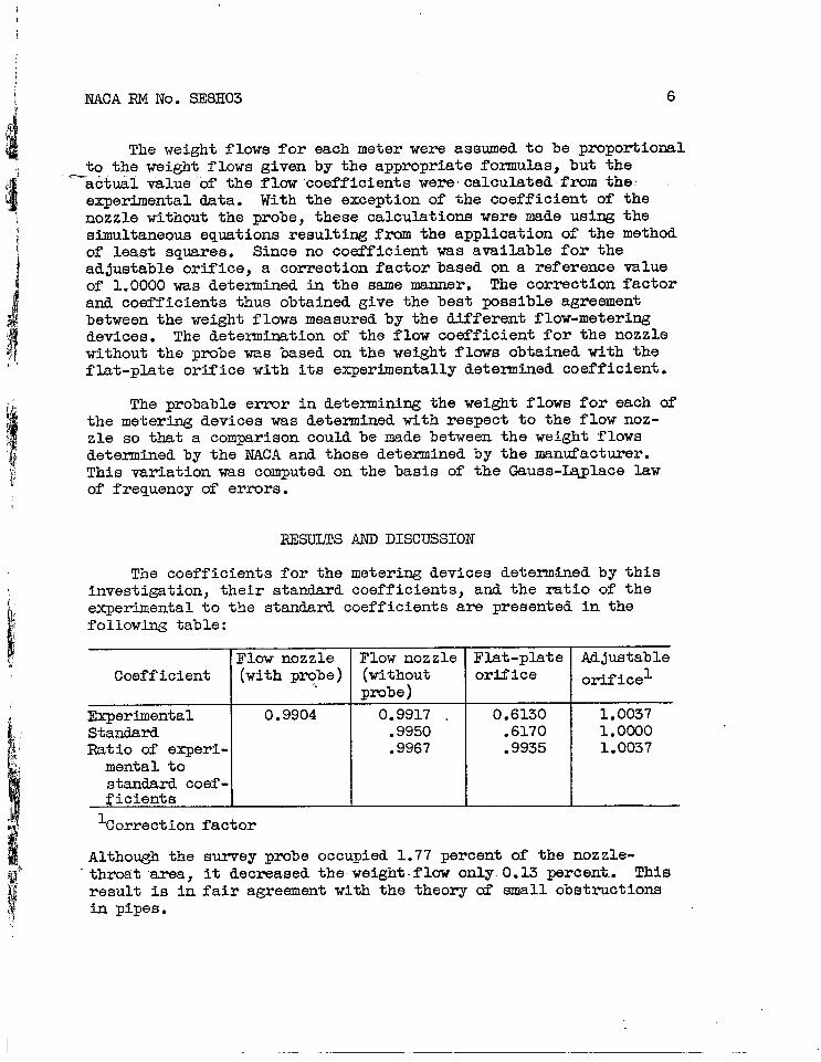
The weight flows for each meter were assumed to be proportional to the weight flows given by the appropriate formulas, but the
-a&&f valueof the flowcoefficients-were~calculated-fmm the: experimental data. With the exception of the coefficient of the nozzle without the probe, these calculations were made using the simultaneous equations resulting from the application of the method of least squares. Since no coefficient was available for the adjustable orifice, a correction factor based on a reference value of 1.0000 was determined in the same manner. The correction factor and coefficients thus obtained give the best possible agreement between the weight flows measured by the different flow-metering devices. The determination of the flow coefficient for the nozzle without the probe was based on the weight flows obtained with the flat-plate orifice with its experimentally determined coefficient.
The probable error in determining the weight flows for each of the metering devices was determined with respect to the flow noz- zle so that a comparison could be made between the weight flows determined by the NACA and those determined by the manufacturer. This variation was computed on the basis of the Gauss-@place law of frequency of errors.
RESULTS AND DISCTJSSION
The coefficients for the metering devices determ<ined by this investigation, their standard coefficients, and the ratio of the experimental to the standard coefficients are presented in the following table:
Flow nozzle Coefficient (with prqP*>
Experimental 0.9904 Standard Ratio of eqeri-
mental to standard coef - ficients
'Correction factor
Flow nozzle 1 Flat-plate (without
I orifice
pmbe) 0.9917 _ 0.6130
.9950 .6170
.9967 .9935
Adjustable orifice 1
1.0037 1.0000 1.0037
Although the survey probe occupied 1.77 percent of the nozzle- throa't'area, it decreased the.weightflow only-O.13 percent. This result is in fair agreement with the theory of small obstructions in pipes.

r--
NACA RM No. SE8HO3 7
The coefficient for the flow nozzle used by the akanufaoturer v ._ I -Y.WI 0..33 percent higher than the experimentally determined coef-
I !!I
ficient. The use of the experQnenta%iy deter&.&h correction factor , for the adjustable orifice would yield weight flows 0.37 percent ,a 1 higher than those obtained in the compressor tests. The weight flows
i measured by these two meters should, therefore, vary by only 0.70 percent. The experimentally determtied coefficient for the
li
(
flat-plate orifice was 0.65 percent lower than the coefficient determined from reference 3.
It ,, ,,/ i The flow nozzle was used as a basis for determining the prob-
1 -j ii
able variation of the weight flows measured by the other air- metering devices so that a direct comparison could be obtained between the weight flows measured in the engine and ccmpressor tests. These variations are presented in the following table:
Probable varia- tion with nozzle
Surveys across nozzle throat
Flat-plate orifice Adjustable orifice
ti.0050
M.0032 Zto.0039
The variations among the meters are within exuerimental error. Although the average weight flows measured tith the adjustable orifice are 0.70 percent lower than the weight flows measured with the flow nozzle, the probable variation about this mean is *0.39 percent. The close agreement between the flow nozzle and the adjustable orifice clearly shows that the weight-flow discrep- ancy of appromtely 4 percent between the results of the 533-A-23 compressor investigation by NACA and the engine tests conducted by the manufacturer was not caused by errors in flow metering. The greater part of the discrepancy is now attributable to the effect of inlet pressure on the compressor weight flow. As shown in reference 1, the compressor weight flow did change with inlet pressure but, because of power limitations, the maximum attainable inlet pressure was 14 inches mercury absolute as com- pared with 30 inches mercury absolute used in the engine tests.
1 5 :if ” LSUMMRYOFRESUITS ,...
Over a range of weight flows from 18 to 45 pounds per second the average weight flows measured with the adjustable orifice are
_ ..-. . ._.-

! NACA RM No. SE8HO3 8 j $
7' 0.70 percent lower than the weight flows measured with the flow noz-
b zle, the probable variation about this mean being equal to i0.39 per- "'cent. The greater-part of the discrepancy in weight flow--of approxi-
G mately 4 percent between the engine and compressor tests is therefore
i2 attributable to the effect of inlet pressure.
'! Ii !I,
i
Flight Propulsion Research Laboratory,
I National Advisory Committee for Aeronautics,
'I Cleveland, Ohio, August 3, 1948. I
j' d mAkiL4-t
Karl Kovach, Aeronautical Research
Scientist.
Approved: Robert 0. Bullock,
Aeronautical Research Scientist.
Aeronautical Engineer.
rl
Oscar W. Schey, Aeronautical Research
Scientist.
REFJBENCES .
1. Beede, William L., and Kottas, Harry: Performance of 533-A-23 Turbojet-Engine Compressor. I - Over-all Performance Charac- teristics of Compressor with 17-Blade Impeller. NACA RM No. SE8F15, U. S. Air Force, 1948.
2. Moss, Sanford A.: Measurement of Flow of Air and Gas with Nozzles. ASME Trans., APM-3, Vol. 50, No. 1, 1928, pp. l-15.

,$ NACA RM No. S$SH03 9 :J ;F
f; .a 7) _o iI
% 9 ii 4
3. Anon.: ibfoxmation on Instruments and Apparatus. Power Test Codes Pt V, ch. 4, ASME, 1940. .?- . ..r ~. :,, ., ) :,
4. Anon.: Standards for Discharge Measurement with.Standardi&d Nozzles and Orifices. NACA TM No. 952, 1940. '
i

ig - “‘. -.rv=- --cp --. ~~ :c
I Y-
Four corner static- ivp--l,3 pipe diameters ---- -* pressure taps
-1 pipe diameter~~~-
/Two total-temperature thermocouples
.’
Figure 1. - Inatrumenftrtlon of submerged flat-plate square-edge odfioe,
0

P ‘9. “Y...r”?-.
/ jy,
Total-temperat
-Wood panel
-Static-pressure taps
Fixed total-pressure probe
Movable total-pressure BurVeJ
probe
‘ ~---y-y---,= k,N$JA/
Figure 2. - Instrumentation of flaw nozzle.

.q- ~-- -- -
; !I
_-’ / ; 1)
RM No. SE8H03
L.’ m .. . . . . ./ ,... 1~ ,_(~,
j-26.50"-----(
Four static- preseure tape 900 apart
---A ,----Four mrvey-
i 29.25" --J Lx-
Section A-A
StEbtlon (in’.) st-3.tion &I station 0.b 1 0.015 I.3 4.875 25 13.875 2 .125 14 5.625 26 14.625 3 .250 15 6.375 27 15.375 4 .375 16 7.125 28 15.875 5 .625 17 7.875 29 16.375 6 .875 18 8.625 30 16.875 7 1.125 19 9.375 31 17.125 a 1.625 20 10.125 32 17.375 9 2.125 21 10.875 33 17.625
10 2.625 22 11.625 34 17.750 11 3.375 23 12.375 35 17.875 12 4.125 24 13.125 36 17.985
probe position13 450 apart
Figure 3. - Survey atatlons acrom nozzle throat.

“_ ?KK . -‘“--v+y
1 CA- c - - &inter line of : hole and tip of pointer MOO, apart; /
I
diam.
I Section H-A
Figure 4. - Movable survey total-pressure probe.

ilg *p
..,
’ I’
.I
,, $.
: .-.
%
.‘*:,.
. ..’
; a,
:
.’ ,-
,p
: ‘;
.: .
: ‘k.
‘r’
,./
/
‘4 :,
I i-
: h,
,
:, ,:(
;I,
- ,*:
;:;
‘+
.: .’
i ..L
_.
I! !‘.
:’
i !
i ‘4
1.’
*:.,-
! 3
1 .‘.
/
gi”.
;i I,.
1.
.
,(.
.,,
‘8’
.‘f
: I_


![Low-Speed Aerodynamic Characteristics of NACA 0012 …naca.central.cranfield.ac.uk/reports/arc/rm/3726.pdf · · 2013-12-05Low-Speed Aerodynamic Characteristics of NACA 0012 Aerofoi]](https://static.fdocuments.us/doc/165x107/5aa786827f8b9a50528c845f/low-speed-aerodynamic-characteristics-of-naca-0012-naca-aerodynamic-characteristics.jpg)


![CENTRAL SHEEP & WOOL RESEARCH INSTITUTE Avikanagar … · nwjHkk"k % 01437&220177 QDl ua- +91&01437&220163 dsUnzh; HksM ++ ,oa Åu vuqla/kku laLFkku vfodkuxj] rg0 ekyiqjk] ftyk&Vkd](https://static.fdocuments.us/doc/165x107/5e6a0a3a5ffd4a59d1680370/central-sheep-wool-research-institute-avikanagar-nwjhkkk-01437220177.jpg)
