NAC-2500 User Manual - NITGEN NAC-2500 Terminal User Manual DC1-0060A...( NAC-2500 ) 1.user check...
83
NAC-2500 User Manual
Transcript of NAC-2500 User Manual - NITGEN NAC-2500 Terminal User Manual DC1-0060A...( NAC-2500 ) 1.user check...
NAC-2500 User Manual
- 2 -
ⓒ Copyright 2003-2008 NITGEN Co., Ltd.
All rights reserved
To Contact Us Tel. +82-80-060-1600
(Toll Free)
Fax. +82-2-513-2191 E-mail: [email protected]
URL: http://www.nitgen.com
Reproduction of part or all of the contents in any form is prohibited
other than in accordance with the permissions.
Product specification can be changed and upgraded to improve
functionality without prior notice.
NITGEN, NITGEN logo are registered trademark of NITGEN.
- 3 -
Table of Contents
CHAPTER 1. INTRODUCTION .................................................................... 5
1.1 Product Introduction......................................................................................... 5
1.2 Product Features and Specification.................................................................. 7
CHAPTER 2. HOW TO USE....................................................................... 12
2.1 Detailed Product Parts .....................................................................................12
2.2 LCD Screen Layout........................................................................................14
2.3 Fingerprint Use.................................................................................................15
2.4 Authentication...................................................................................................16 2.4.1Fingerprint ....................................................................................................16 2.4.2Password.......................................................................................................21 2.4.3RF Card (optional)........................................................................................22 2.4.3Others: Automatic Attendance Mode............................................................23
CHAPTER 3. ENVIRONMENT SETTING................................................... 24
3.1 Menu Composition ...........................................................................................24
3.2 Entering into Menu ..........................................................................................27
3.3 Basic Menu........................................................................................................28
3.4 Detailed Menu...................................................................................................30 3.4.1 User Management........................................................................................30
- 4 -
3.4.2 Fingerprint Sensor Setting ...........................................................................45 3.4.3 UI (User Interface) Setting ..........................................................................53 3.4.4 System Setting .............................................................................................56 3.4.5 Network Setting........................................................................................65 3.4.6 Cofirmation of Terminal Information .......................................................71 3.4.7 Factory Default Setting................................................................................73
APPENDIX 1: NETWORK CONNECTION ERROR AND SOLUTIONS..... 77
APPENDIX 2: TERMINAL INITIALIZATION ERROR AND SOLUTIONS .. 79
APPENDIX 3: LAW AND REGULATION.................................................... 80
APPENDIX 4: WIEGAND PROTOCOL FORMAT ...................................... 81
APPENDIX 5 : EMERGENCY SCREEN..................................................... 83
- 5 -
Chapter 1. Introduction
1.1 Product Introduction
Overview
The use of biometrics system continuously increases in various
authentication systems and in areas that require a higher level
of security because of its ease of use and economical benefits.
Among a number of biometrics system, a fingerprint recognition
system is not only easy to use but also enables economical
product development. It takes up the most part of the market
as it allows a wide variety of application. NITGEN, a leader
in the fingerprint recognition area, has provided fingerprint
recognition solutions for the management of PC security,
knowledge, safe, access control, electronic payment and
financial clearings. Continuous R&D activities and quality
management ensure that NITGEN meets evolving needs and demands
of the market and the customers.
NITGEN access control system is a culmination of world-renowned
technologies from NITGEN including fingerprint recognition
algorithms, optical sensor, embedded design and software
applications. Unlike legacy access control systems that use
only password and ID card, it provides the ease of use and tight
security with no risk of forgetting password, stolen cards or
forgery. The system is designed to provide maximum operational
efficiency over the network by enabling remote monitoring on
terminals that have been independent so far.
NITGEN access control system allows various combinations of FR
card, password and fingerprints. It also meets the common set
of requirements and special needs in the corporate and
- 6 -
government sectors with such functions as shortened ID, 1:N
matching and voice guidelines.
The manual gives in-depth explanation as to how to use NITGEN
access control terminal (NAC-2500).
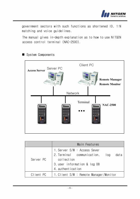
System Components
Main Features
Server PC
1. Server S/W : Access Sever 2. Terminal communication, log data
collection
3. user information & log DB 4. authentication
Client PC 1. Client S/W : Remote Manager/Monitor
Network
Server PC
Terminal
Client PC
NAC-2500
Access Server
Remote Manager Remote Monitor
- 7 -
2. user registration and other management 3. Terminal status and event monitoring
Terminal
( NAC-2500 )
1. user check and authentication 2. access door control
NITGEN access control terminal(NAC-2500) can be used alone for
full functionality or can be used in connection with the network
together with admin programs (Access Server, Remote Manager,
Remote Monitor) in order to reduce the number of terminals and
to ensure an easier and a more effective management. Server
S/Wand Client S/W can be placed within one PC.
1.2 Product Features and Specification
Product Features
NITGEN access control system (NAC-2500) has the following
features.
① access control and management on small & medium number of
users
② a combination of various authentication methods
(fingerprint, password, RF card)
③ network-based access control on terminals for multiple
users
④ easy remote management on the system (Server/Client PC can
be separated)
⑤ view on user’s access history and various additional
functions
- 8 -
⑥ real-time access monitoring
⑦ access control by period and time
⑧ SDK (S/W Developer’s Kit) for the development of
application programs such as attendance management program
(separate)
⑨ high-speed 1:N authentication
⑩ enhanced user-friendliness and ease of use (shortened ID,
Auto-on)
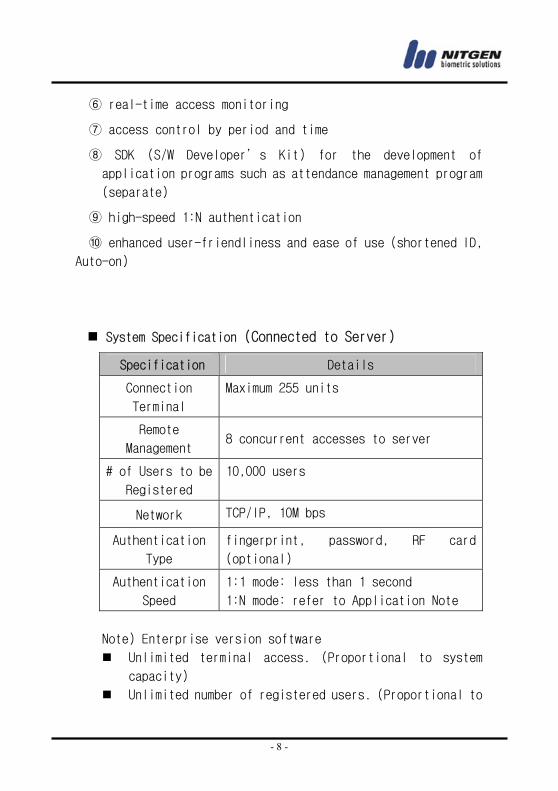
System Specification (Connected to Server)
Specification Details
Connection
Terminal
Maximum 255 units
Remote
Management 8 concurrent accesses to server
# of Users to be
Registered
10,000 users
Network TCP/IP, 10M bps
Authentication
Type
fingerprint, password, RF card
(optional)
Authentication
Speed
1:1 mode: less than 1 second
1:N mode: refer to Application Note
Note) Enterprise version software
Unlimited terminal access. (Proportional to system
capacity)
Unlimited number of registered users. (Proportional to
- 9 -
system capacity)
1:1 server authentication only.
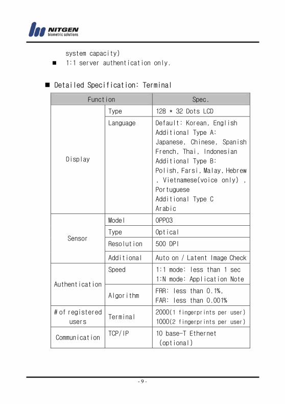
Detailed Specification: Terminal
Function Spec.
Type 128 * 32 Dots LCD
Display
Language Default: Korean, English
Additional Type A:
Japanese, Chinese, Spanish
French, Thai, Indonesian
Additional Type B:
Polish, Farsi, Malay, Hebrew
, Vietnamese(voice only) , Portuguese
Additional Type C
Arabic
Model OPP03
Type Optical
Resolution 500 DPI Sensor
Additional Auto on / Latent Image Check
Speed 1:1 mode: less than 1 sec
1:N mode: Application NoteAuthentication
Algorithm FRR: less than 0.1%,
FAR: less than 0.001%
# of registered
users Terminal
2000(1 fingerprints per user)
1000(2 fingerprints per user)
CommunicationTCP/IP 10 base-T Ethernet
(optional)
- 10 -
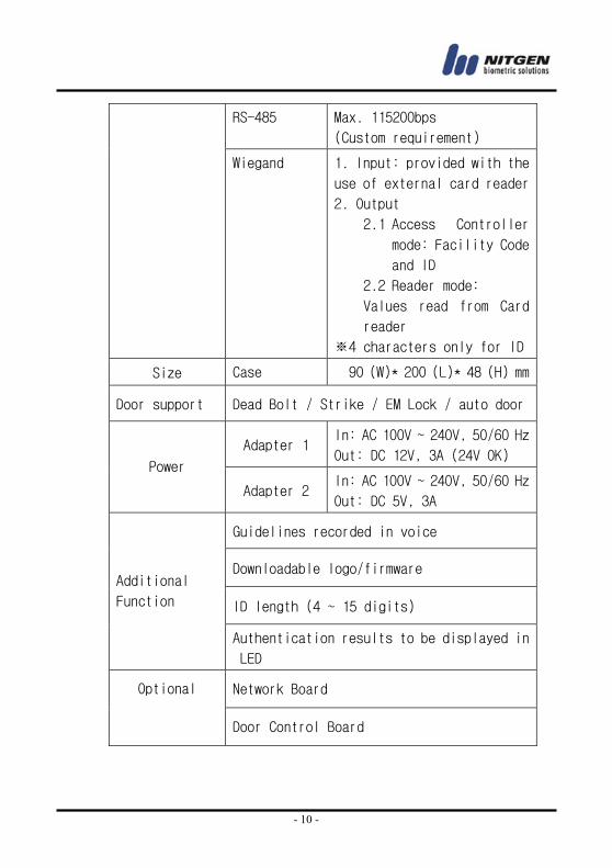
RS-485 Max. 115200bps
(Custom requirement)
Wiegand 1. Input: provided with the
use of external card reader
2. Output
2.1 Access Controller
mode: Facility Code
and ID
2.2 Reader mode: Values read from Card
reader
※4 characters only for ID
Size Case 90 (W)* 200 (L)* 48 (H) mm
Door support Dead Bolt / Strike / EM Lock / auto door
Adapter 1 In: AC 100V ~ 240V, 50/60 Hz
Out: DC 12V, 3A (24V OK) Power
Adapter 2 In: AC 100V ~ 240V, 50/60 Hz
Out: DC 5V, 3A
Guidelines recorded in voice
Downloadable logo/firmware
ID length (4 ~ 15 digits)
Additional
Function
Authentication results to be displayed in
LED
Network Board Optional
Door Control Board
- 11 -
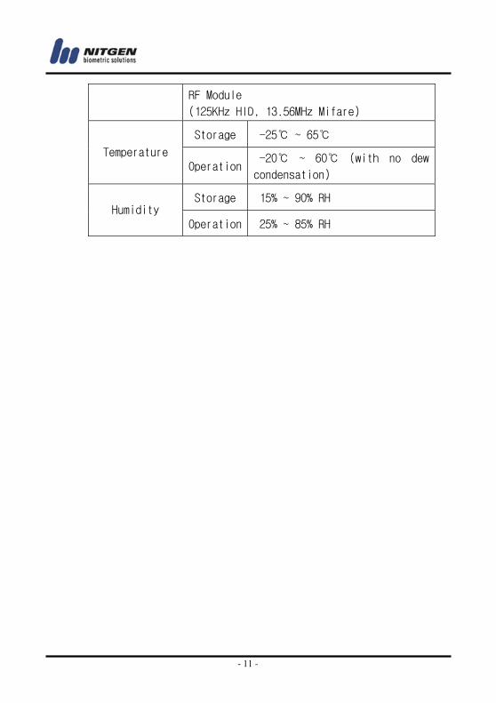
RF Module
(125KHz HID, 13.56MHz Mifare)
Storage -25℃ ~ 65℃
Temperature Operation
-20℃ ~ 60℃ (with no dew
condensation)
Storage 15% ~ 90% RH Humidity
Operation 25% ~ 85% RH
- 12 -
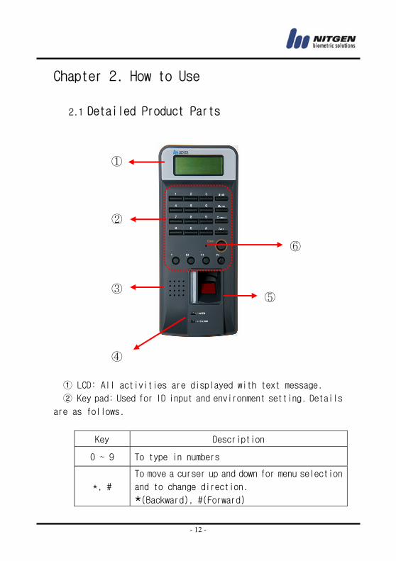
Chapter 2. How to Use
2.1 Detailed Product Parts
① LCD: All activities are displayed with text message.
② Key pad: Used for ID input and environment setting. Details
are as follows.
Key Description
0 ~ 9 To type in numbers
*, #
To move a curser up and down for menu selection
and to change direction.
*(Backward), #(Forward)
①
②
③⑤
④
⑥
- 13 -
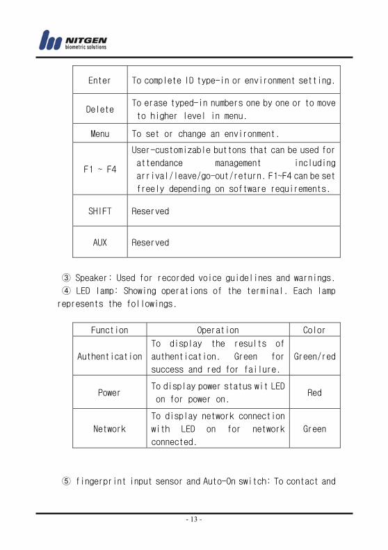
Enter To complete ID type-in or environment setting.
Delete To erase typed-in numbers one by one or to move
to higher level in menu.
Menu To set or change an environment.
F1 ~ F4
User-customizable buttons that can be used for
attendance management including
arrival/leave/go-out/return. F1~F4 can be set
freely depending on software requirements.
SHIFT Reserved
AUX Reserved
③ Speaker: Used for recorded voice guidelines and warnings.
④ LED lamp: Showing operations of the terminal. Each lamp
represents the followings.
Function Operation Color
Authentication
To display the results of
authentication. Green for
success and red for failure.
Green/red
Power To display power status wit LED
on for power on. Red
Network
To display network connection
with LED on for network
connected.
Green
⑤ fingerprint input sensor and Auto-On switch: To contact and
- 14 -
take fingerprint. With no operation of key pad, fingerprint will
be automatically input by touching the fingerprint input sensor
with a finger.
⑥ Reset switch: To reset the terminal if the terminal is not
in normal operation unexpectedly.
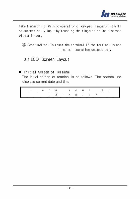
2.2 LCD Screen Layout
Initial Screen of Terminal The initial screen of terminal is as follows. The bottom line
displays current date and time.
P ㅣ a c e Y o u r F P
1 3 : 4 6 : 1 7
- 15 -
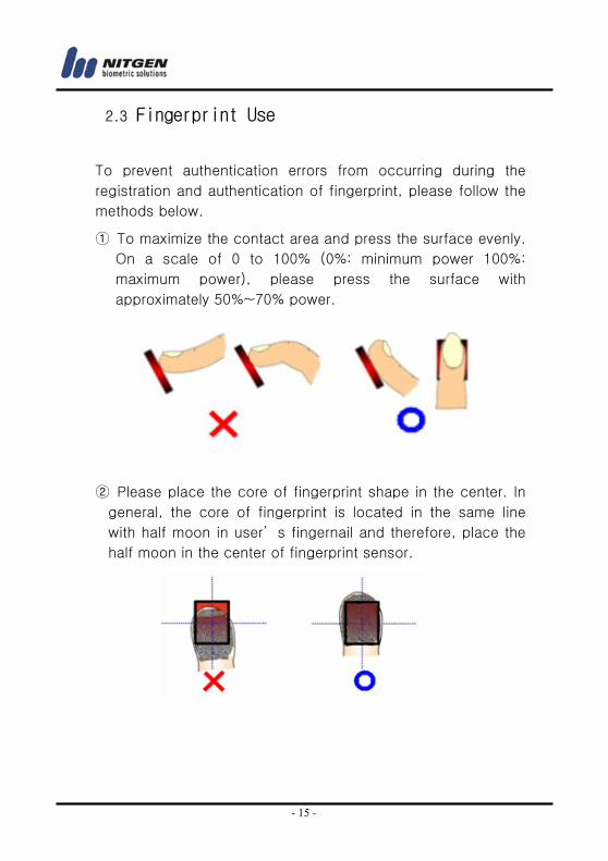
2.3 Fingerprint Use
To prevent authentication errors from occurring during the
registration and authentication of fingerprint, please follow the
methods below.
① To maximize the contact area and press the surface evenly.
On a scale of 0 to 100% (0%: minimum power 100%:
maximum power), please press the surface with
approximately 50%~70% power.
② Please place the core of fingerprint shape in the center. In
general, the core of fingerprint is located in the same line
with half moon in user’ s fingernail and therefore, place the
half moon in the center of fingerprint sensor.
- 16 -
2.4 Authentication
NITGEN Access Control System recognizes fingerprint, password,
and RF CARD (optional) for authentication. Users can get
authentication by freely choosing any method depending on
their own environment.
2.4.1Fingerprint
The following methods can be used to check access right with
fingerprints.
• 1:1 Match It is to input fingerprint after feeding an ID that is already
registered. It matches input fingerprint with an already
registered fingerprint for a specific ID on a 1:1 basis. The
time required for authentication for 1:1 match is substantially
short regardless of the number of users. There is no need to
set the mode in a system. Authentication procedure begins
when fingerprint is input after ID is typed in.
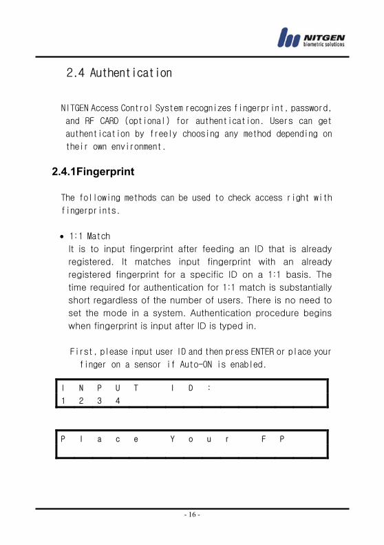
First, please input user ID and then press ENTER or place your
finger on a sensor if Auto-ON is enabled.
I N P U T I D :
1 2 3 4
P l a c e Y o u r F P
- 17 -
• 1:N Match It does authentication only with a registered fingerprint. The
authentication procedure is simple but it can take relatively
longer time than the 1:1 match when a number of users try to
access the system. There is no need to set the mode in a
system. A simple input of fingerprint will initiate the
authentication process. If it takes too long for 1:N authentication
due to too many users, please try ‘ 1:N time set’ in which
authentication is retried by typing in ID when authentication is
not completed within in the set time. Please refer to the following
details for ‘ 1:N authentication time.’
• Authentication with Shortened ID (SID) Users can select ID with characters between 4~15
depending on default setting. Shortened authentication is
designed to simplify an ID input procedure in which the
authentication begins with only a couple of characters from a
S u c c e s s !
P l a c e Y o u r F P
S u c c e s s !
- 18 -
set ID to be input. For example, if a user uses an ID of 1234
567, the 1:N match against any IDs starting with 12xxxxx is
initiated in the system when the user inputs 12 followed by a
fingerprint. There is no need to set the mode in a system.
• Authentication for attendance mode It does authentication by using function keys (F1~F4).
Before trying authentication, please press an appropriate
function key and proceed with authentication. In this case,
the result associated with the pressed function key remains
in log history which can be used for attendance data. For
example, if a user presses F1 and then inputs an ID, the
ID+F1 remain in log history. Also, if a user presses F1 only
and then proceeds with 1:N authentication, an appropriate ID
is searched to remain ‘ ID+F1’ record.
The following shows an LCD display when pressing F1.
I N P U T I D :
1
P l a c e Y o u r F P
S u c c e s s !
F 1 - I N P U T I D :
- 19 -
* In order to use attendance mode, the option of terminal is
set in by Menu-> system options(4) -> Function mode(4) ->
T&A
• Expanded attendance mode It does authentication by using extended function keys
(F11~F19, F21~F29, F31~F39, F41~F49)
Before trying authentication, please press an appropriate
function key and select approprating number with a Left key (*)
or a Right Key (#). In case of pressing the left key, it is
decressed the number of function. And in case of pressing
Left Key (*), it is incressed the number of function displayed
in LCD.
* Right key input (#)
P l a c e Y o u r F P
S u c c e s s !
F 1 - I N P U T I D :
1 2 3 4
F 1 1 - I N P U T I D :
1 2 3 4
- 20 -
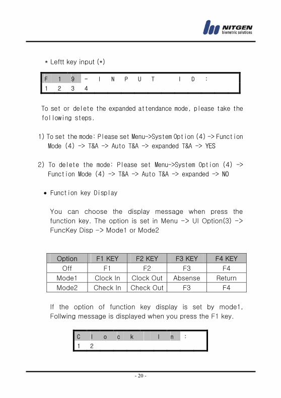
* Leftt key input (*)
To set or delete the expanded attendance mode, please take the
following steps.
1) To set the mode: Please set Menu->System Option (4) -> Function
Mode (4) -> T&A -> Auto T&A -> expanded T&A -> YES
2) To delete the mode: Please set Menu->System Option (4) ->
Function Mode (4) -> T&A -> Auto T&A -> expanded -> NO
• Function key Display
You can choose the display message when press the
function key. The option is set in Menu -> UI Option(3) ->
FuncKey Disp -> Mode1 or Mode2
Option F1 KEY F2 KEY F3 KEY F4 KEY
Off F1 F2 F3 F4
Mode1 Clock In Clock Out Absense Return
Mode2 Check In Check Out F3 F4
If the option of function key display is set by mode1,
Follwing message is displayed when you press the F1 key.
C l o c k I n :
1 2
F 1 9 - I N P U T I D :
1 2 3 4
- 21 -
* * In order to use Function key display, the option of terminal
is set by Menu-> system options(4) -> Function mode(4)
-> T&A
• Authentication failure message
The following messages are displayed depending on authentication
method and causes of failure.
An error message for matching failure.
The following message is displayed when image capturing is
failed. When the message is displayed, please check if
your fingerprint is too dry or too wet.
2.4.2Password
It checks the right to access by using 4~8 digit password and
it is used in special occasions including damaged
fingerprint.
M a t c h i N g E r r o r
T i m e o u T !
- 22 -
Password can be set up to 8 digits.
2.4.3RF Card (optional)
User identity is confirmed through a RF CARD that he or she has.
By registering RF CARD numbers in the system, the use of lost
or stolen card can be prevented. To initiate authentication
by using a RF CARD, you can either contact RF card when the
initial screen appears or contact RF card when the following
message is displayed after typing in user ID.
Please place your card in front of the fingerprint sensor when
the following message appears.
The following message appears in case of success.
I N P U T I D :
1 2 3 4
I N P U T P A s s w d
: * * * * *
C o n t a c t R F c a r d
O n S e n s o r
S u c c e s s !
- 23 -
2.4.3Others: Automatic Attendance Mode
The result of attendance can automatically remain in log history
only with general 1:N authentication. When a specific attendance
status is repeated many times, the user does not need to take
trouble to press the same function key (F1~F4) each time.
In an automatic attendance mode, the initial screen changes as
follows and when the 1:N match is tried, the authentication
result is automatically attached with the relevant attendance
status.
To set or delete the automatic attendance mode, please take the
following steps.
1) To set the mode: Please set Menu->System Option (4) -> Function
Mode (4) -> T&A -> Auto T&A -> YES
2) To delete the mode: Please set Menu->System Option (4) ->
Function Mode (4) -> T&A -> Auto T&A -> NO
2.4.4 Others : Free Scan(1:1 match only)
In free scan mode (1:1match only), 1:N match and Authentication
with Shortened ID are forbidden. The option is set by MENU -> FP
OPTION (2) -> Free Scan Mode (7) -> YES or NO
It’s possible to use all of authentications (1:1, 1:N, SID match),
if the option is set in“NO”.
F 1 - I N P U T I D :
1 2 3 4
- 24 -
Chapter 3. Environment Setting
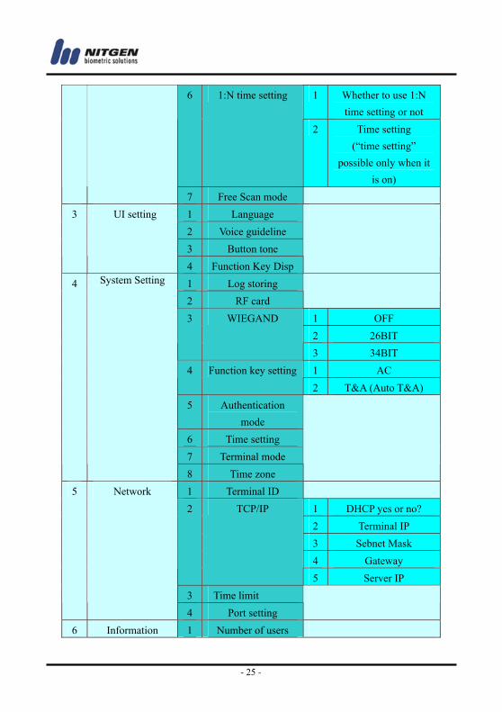
3.1 Menu Composition
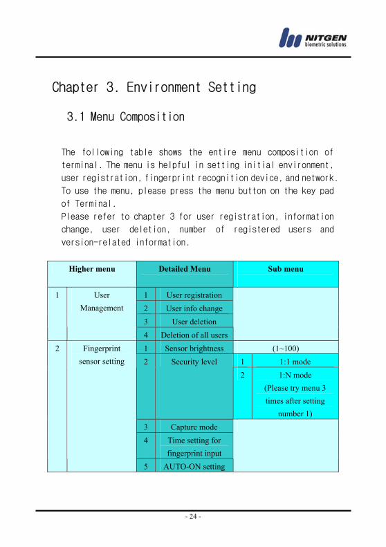
The following table shows the entire menu composition of
terminal. The menu is helpful in setting initial environment,
user registration, fingerprint recognition device, and network.
To use the menu, please press the menu button on the key pad
of Terminal.
Please refer to chapter 3 for user registration, information
change, user deletion, number of registered users and
version-related information.
Higher menu Detailed Menu
Sub menu
1 User registration 2 User info change 3 User deletion
1 User Management
4 Deletion of all users
1 Sensor brightness (1~100) 1 1:1 mode 2 Security level 2 1:N mode
(Please try menu 3 times after setting
number 1) 3 Capture mode 4 Time setting for
fingerprint input
2 Fingerprint sensor setting
5 AUTO-ON setting
- 25 -
1 Whether to use 1:N time setting or not
6 1:N time setting
2 Time setting (“time setting”
possible only when it is on)
7 Free Scan mode 1 Language 2 Voice guideline 3 Button tone
3 UI setting
4 Function Key Disp
1 Log storing 2 RF card
1 OFF 2 26BIT
3 WIEGAND
3 34BIT 1 AC 4 Function key setting2 T&A (Auto T&A)
5 Authentication mode
6 Time setting 7 Terminal mode
4 System Setting
8 Time zone
1 Terminal ID 1 DHCP yes or no? 2 Terminal IP 3 Sebnet Mask 4 Gateway
2 TCP/IP
5 Server IP 3 Time limit
5 Network
4 Port setting
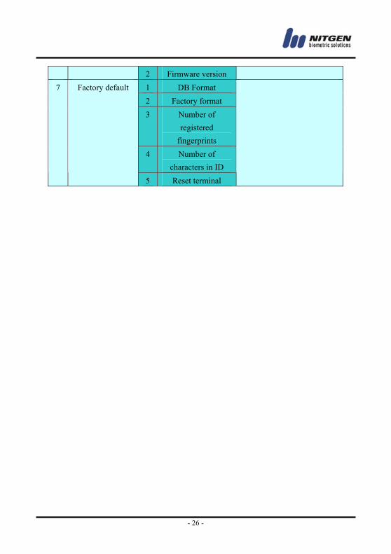
6 Information 1 Number of users
- 26 -
2 Firmware version 1 DB Format 2 Factory format 3 Number of
registered fingerprints
4 Number of characters in ID
7 Factory default
5 Reset terminal
- 27 -
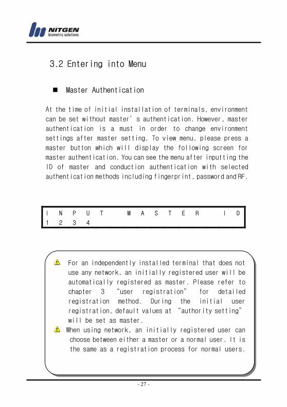
3.2 Entering into Menu
Master Authentication
At the time of initial installation of terminals, environment
can be set without master’s authentication. However, master
authentication is a must in order to change environment
settings after master setting. To view menu, please press a
master button which will display the following screen for
master authentication. You can see the menu after inputting the
ID of master and conduction authentication with selected
authentication methods including fingerprint, password and RF.
I N P U T M A S T E R I D
1 2 3 4
For an independently installed terminal that does not
use any network, an initially registered user will be
automatically registered as master. Please refer to
chapter 3 “user registration” for detailed
registration method. During the initial user
registration, default values at “authority setting”
will be set as master.
When using network, an initially registered user can
choose between either a master or a normal user. It is
the same as a registration process for normal users.
- 28 -
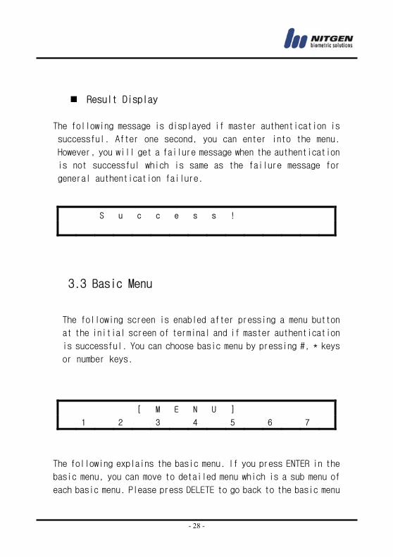
Result Display
The following message is displayed if master authentication is
successful. After one second, you can enter into the menu.
However, you will get a failure message when the authentication
is not successful which is same as the failure message for
general authentication failure.
3.3 Basic Menu
The following screen is enabled after pressing a menu button
at the initial screen of terminal and if master authentication
is successful. You can choose basic menu by pressing #, * keys
or number keys.
The following explains the basic menu. If you press ENTER in the
basic menu, you can move to detailed menu which is a sub menu of
each basic menu. Please press DELETE to go back to the basic menu
S u c c e s s !
[ M E N U ]
1 2 3 4 5 6 7
- 29 -
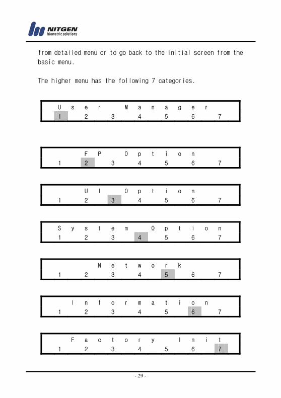
from detailed menu or to go back to the initial screen from the
basic menu.
The higher menu has the following 7 categories.
U s e r M a n a g e r
1 2 3 4 5 6 7
F P O p t i o n
1 2 3 4 5 6 7
U I O p t i o n
1 2 3 4 5 6 7
S y s t e m O p t i o n
1 2 3 4 5 6 7
N e t w o r k
1 2 3 4 5 6 7
I n f o r m a t i o n
1 2 3 4 5 6 7
F a c t o r y I n i t
1 2 3 4 5 6 7
- 30 -
3.4 Detailed Menu
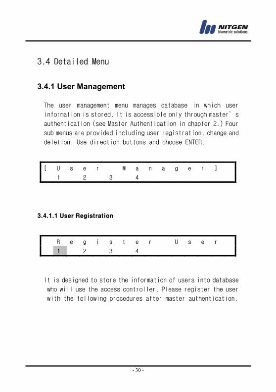
3.4.1 User Management
The user management menu manages database in which user
information is stored. It is accessible only through master’s
authentication (see Master Authentication in chapter 2.) Four
sub menus are provided including user registration, change and
deletion. Use direction buttons and choose ENTER.
3.4.1.1 User Registration
It is designed to store the information of users into database
who will use the access controller. Please register the user
with the following procedures after master authentication.
[ U s e r M a n a g e r ]
1 2 3 4
R e g i s t e r U s e r
1 2 3 4
- 31 -
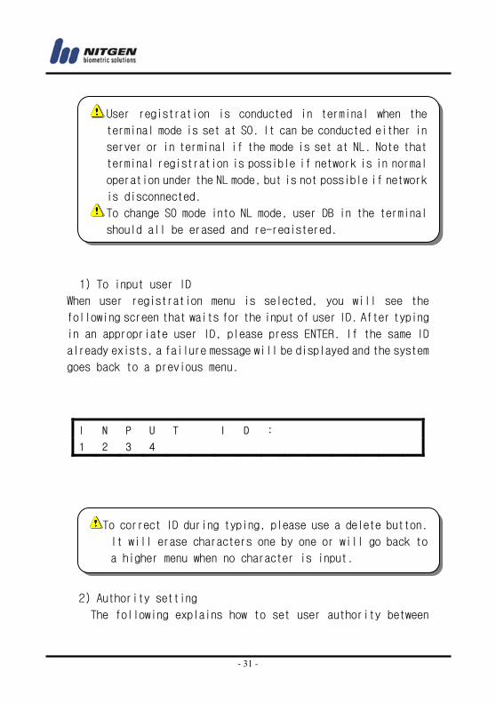
1) To input user ID
When user registration menu is selected, you will see the
following screen that waits for the input of user ID. After typing
in an appropriate user ID, please press ENTER. If the same ID
already exists, a failure message will be displayed and the system
goes back to a previous menu.
2) Authority setting
The following explains how to set user authority between
I N P U T I D :
1 2 3 4
User registration is conducted in terminal when the
terminal mode is set at SO. It can be conducted either in
server or in terminal if the mode is set at NL. Note that
terminal registration is possible if network is in normal
operation under the NL mode, but is not possible if network
is disconnected.
To change SO mode into NL mode, user DB in the terminal
should all be erased and re-registered.
To correct ID during typing, please use a delete button.
It will erase characters one by one or will go back to
a higher menu when no character is input.
- 32 -
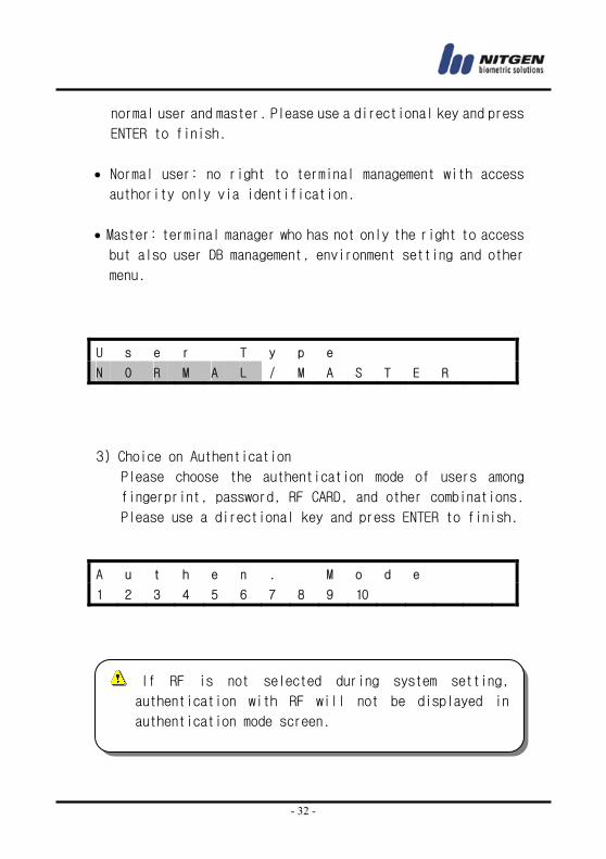
normal user and master. Please use a directional key and press
ENTER to finish.
• Normal user: no right to terminal management with access authority only via identification.
• Master: terminal manager who has not only the right to access but also user DB management, environment setting and other
menu.
3) Choice on Authentication
Please choose the authentication mode of users among
fingerprint, password, RF CARD, and other combinations.
Please use a directional key and press ENTER to finish.
U s e r T y p e
N O R M A L / M A S T E R
A u t h e n . M o d e
1 2 3 4 5 6 7 8 9 10
If RF is not selected during system setting,
authentication with RF will not be displayed in
authentication mode screen.
- 33 -
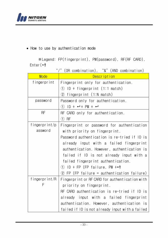
• How to use by authentication mode
※Legend: FP(fingerprint), PW(password), RF(RF CARD),
Enter( )
“/”(OR combination), “&”(AND combination)
Mode Description
fingerprint Fingerprint only for authentication.
① ID + fingerprint (1:1 match)
② fingerprint (1:N match)
password Password only for authentication.
① ID + + PW +
RF RF CARD only for authentication.
① RF
fingerprint/p
assword
Fingerprint or password for authentication
with priority on fingerprint.
Password authentication is re-tried if ID is
already input with a failed fingerprint
authentication. However, authentication is
failed if ID is not already input with a
failed fingerprint authentication.
① ID + FP (FP failure, PW + )
② FP (FP failure = authentication failure)
fingerprint/R
F
Fingerprint or RF CARD for authentication with
priority on fingerprint.
RF CARD authentication is re-tried if ID is
already input with a failed fingerprint
authentication. However, authentication is
failed if ID is not already input with a failed
- 34 -
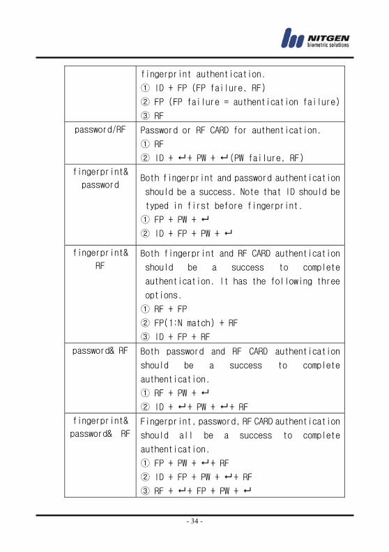
fingerprint authentication.
① ID + FP (FP failure, RF)
② FP (FP failure = authentication failure)
③ RF
password/RF Password or RF CARD for authentication.
① RF
② ID + + PW + (PW failure, RF)
fingerprint&
password Both fingerprint and password authentication
should be a success. Note that ID should be
typed in first before fingerprint.
① FP + PW +
② ID + FP + PW +
fingerprint&
RF
Both fingerprint and RF CARD authentication
should be a success to complete
authentication. It has the following three
options.
① RF + FP
② FP(1:N match) + RF
③ ID + FP + RF
password& RF Both password and RF CARD authentication
should be a success to complete
authentication.
① RF + PW +
② ID + + PW + + RF
fingerprint&
password& RF
Fingerprint, password, RF CARD authentication
should all be a success to complete
authentication.
① FP + PW + + RF
② ID + FP + PW + + RF
③ RF + + FP + PW +
- 35 -
From the above table of authentication methods, shortened ID
authentication can be used for fingerprint authentication
(see 1.6 Authentication of chapter 1.)
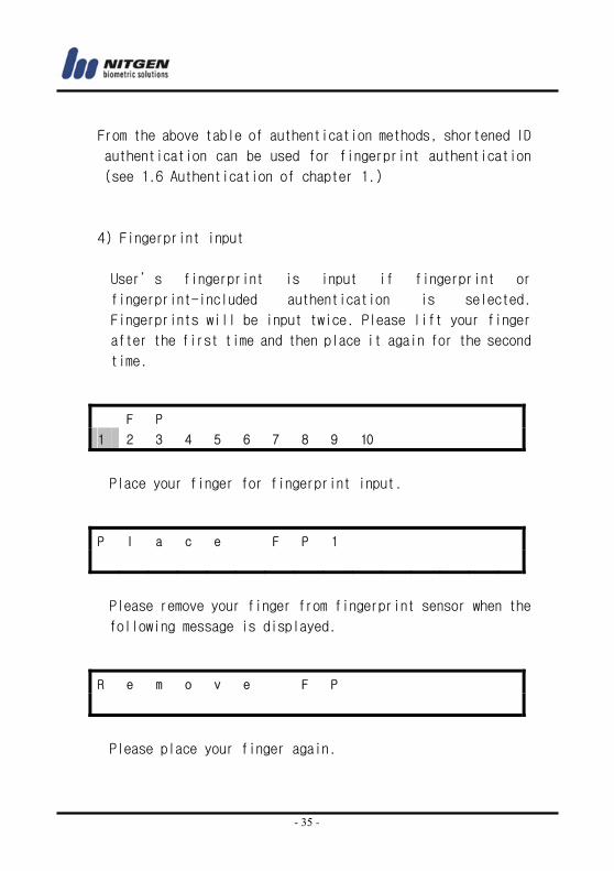
4) Fingerprint input
User’s fingerprint is input if fingerprint or
fingerprint-included authentication is selected.
Fingerprints will be input twice. Please lift your finger
after the first time and then place it again for the second
time.
Place your finger for fingerprint input.
Please remove your finger from fingerprint sensor when the
following message is displayed.
Please place your finger again.
F P
1 2 3 4 5 6 7 8 9 10
P l a c e F P 1
R e m o v e F P
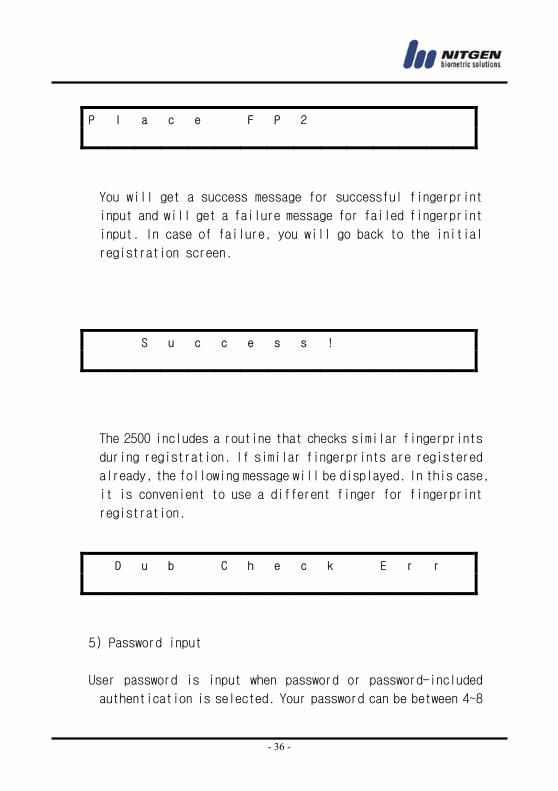
- 36 -
You will get a success message for successful fingerprint
input and will get a failure message for failed fingerprint
input. In case of failure, you will go back to the initial
registration screen.
The 2500 includes a routine that checks similar fingerprints
during registration. If similar fingerprints are registered
already, the following message will be displayed. In this case,
it is convenient to use a different finger for fingerprint
registration.
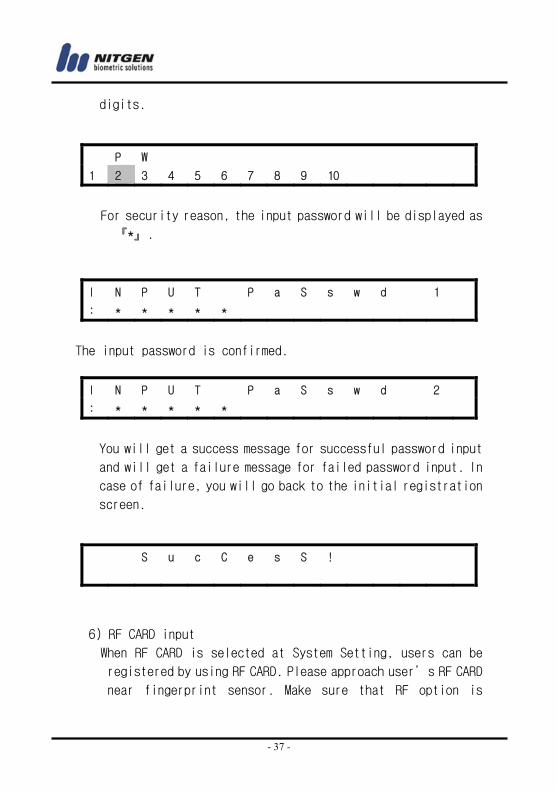
5) Password input
User password is input when password or password-included
authentication is selected. Your password can be between 4~8
P l a c e F P 2
S u c c e s s !
D u b C h e c k E r r
- 37 -
digits.
For security reason, the input password will be displayed as
『*』.
The input password is confirmed.
You will get a success message for successful password input
and will get a failure message for failed password input. In
case of failure, you will go back to the initial registration
screen.
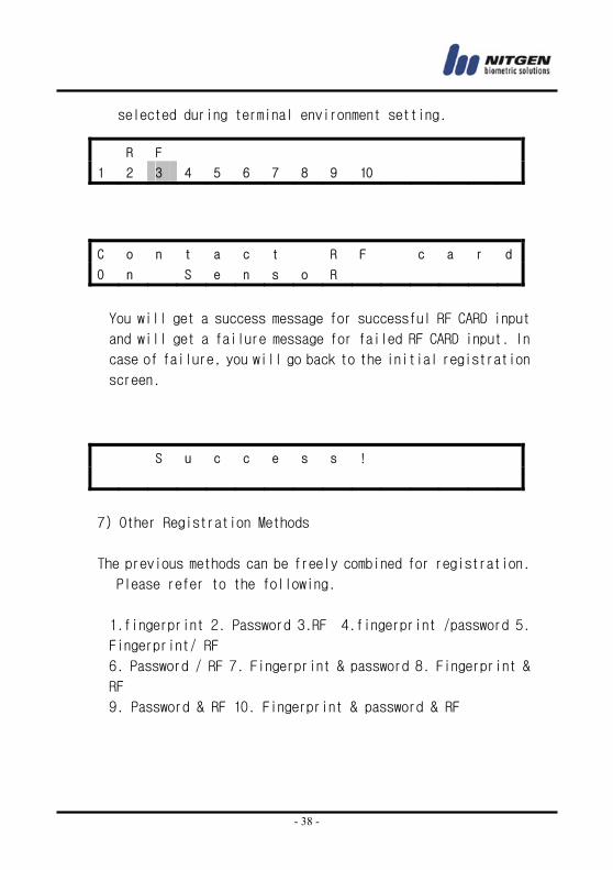
6) RF CARD input
When RF CARD is selected at System Setting, users can be
registered by using RF CARD. Please approach user’s RF CARD
near fingerprint sensor. Make sure that RF option is
P W
1 2 3 4 5 6 7 8 9 10
I N P U T P a S s w d 1
: * * * * *
I N P U T P a S s w d 2
: * * * * *
S u c C e s S !
- 38 -
selected during terminal environment setting.
You will get a success message for successful RF CARD input
and will get a failure message for failed RF CARD input. In
case of failure, you will go back to the initial registration
screen.
7) Other Registration Methods
The previous methods can be freely combined for registration.
Please refer to the following.
1.fingerprint 2. Password 3.RF 4.fingerprint /password 5.
Fingerprint/ RF
6. Password / RF 7. Fingerprint & password 8. Fingerprint &
RF
9. Password & RF 10. Fingerprint & password & RF
R F
1 2 3 4 5 6 7 8 9 10
C o n t a c t R F c a r d
O n S e n s o R
S u c c e s s !
- 39 -
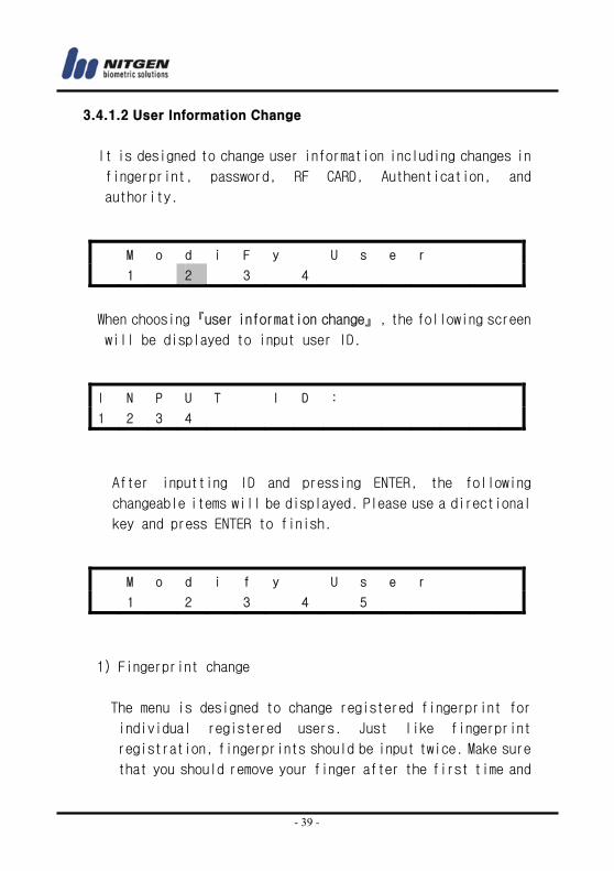
3.4.1.2 User Information Change
It is designed to change user information including changes in
fingerprint, password, RF CARD, Authentication, and
authority.
When choosing『user information change』, the following screen
will be displayed to input user ID.
After inputting ID and pressing ENTER, the following
changeable items will be displayed. Please use a directional
key and press ENTER to finish.
1) Fingerprint change
The menu is designed to change registered fingerprint for
individual registered users. Just like fingerprint
registration, fingerprints should be input twice. Make sure
that you should remove your finger after the first time and
M o d i F y U s e r
1 2 3 4
I N P U T I D :
1 2 3 4
M o d i f y U s e r
1 2 3 4 5
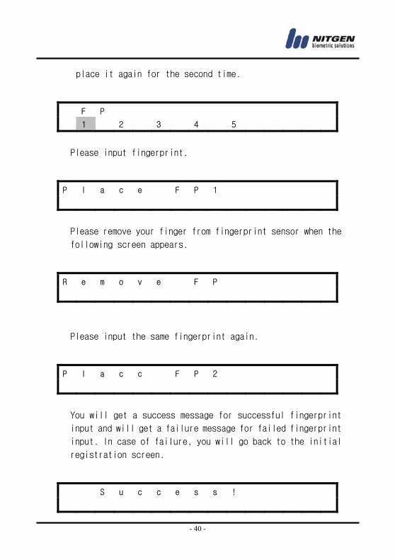
- 40 -
place it again for the second time.
Please input fingerprint.
Please remove your finger from fingerprint sensor when the
following screen appears.
Please input the same fingerprint again.
You will get a success message for successful fingerprint
input and will get a failure message for failed fingerprint
input. In case of failure, you will go back to the initial
registration screen.
F P
1 2 3 4 5
P l a c e F P 1
R e m o v e F P
P l a c c F P 2
S u c c e s s !
- 41 -
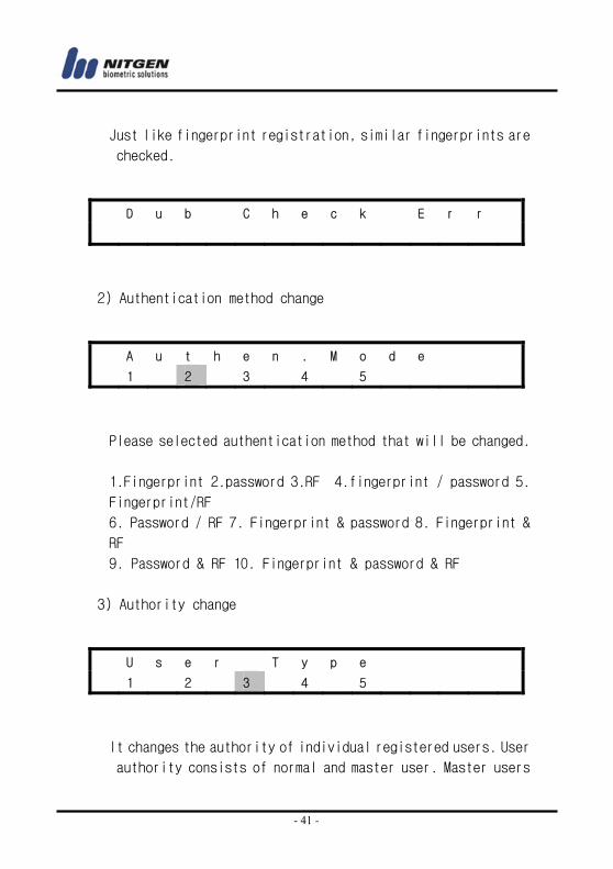
Just like fingerprint registration, similar fingerprints are
checked.
2) Authentication method change
Please selected authentication method that will be changed.
1.Fingerprint 2.password 3.RF 4.fingerprint / password 5.
Fingerprint/RF
6. Password / RF 7. Fingerprint & password 8. Fingerprint &
RF
9. Password & RF 10. Fingerprint & password & RF
3) Authority change
It changes the authority of individual registered users. User
authority consists of normal and master user. Master users
D u b C h e c k E r r
A u t h e n . M o d e
1 2 3 4 5
U s e r T y p e
1 2 3 4 5
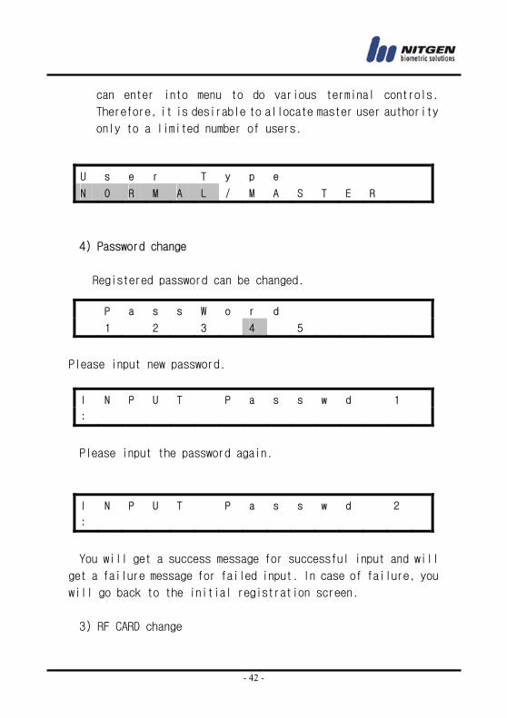
- 42 -
can enter into menu to do various terminal controls.
Therefore, it is desirable to allocate master user authority
only to a limited number of users.
4) Password change
Registered password can be changed.
Please input new password.
Please input the password again.
You will get a success message for successful input and will
get a failure message for failed input. In case of failure, you
will go back to the initial registration screen.
3) RF CARD change
U s e r T y p e
N O R M A L / M A S T E R
P a s s W o r d
1 2 3 4 5
I N P U T P a s s w d 1
:
I N P U T P a s s w d 2
:
- 43 -
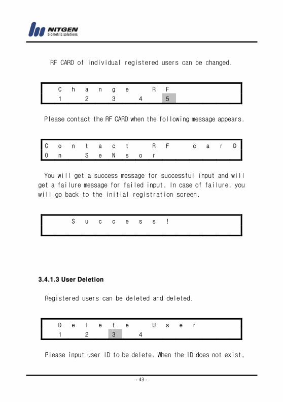
RF CARD of individual registered users can be changed.
Please contact the RF CARD when the following message appears.
You will get a success message for successful input and will
get a failure message for failed input. In case of failure, you
will go back to the initial registration screen.
3.4.1.3 User Deletion
Registered users can be deleted and deleted.
Please input user ID to be delete. When the ID does not exist,
C h a n g e R F
1 2 3 4 5
C o n t a c t R F c a r D
O n S e N s o r
S u c c e s s !
D e l e t e U s e r
1 2 3 4
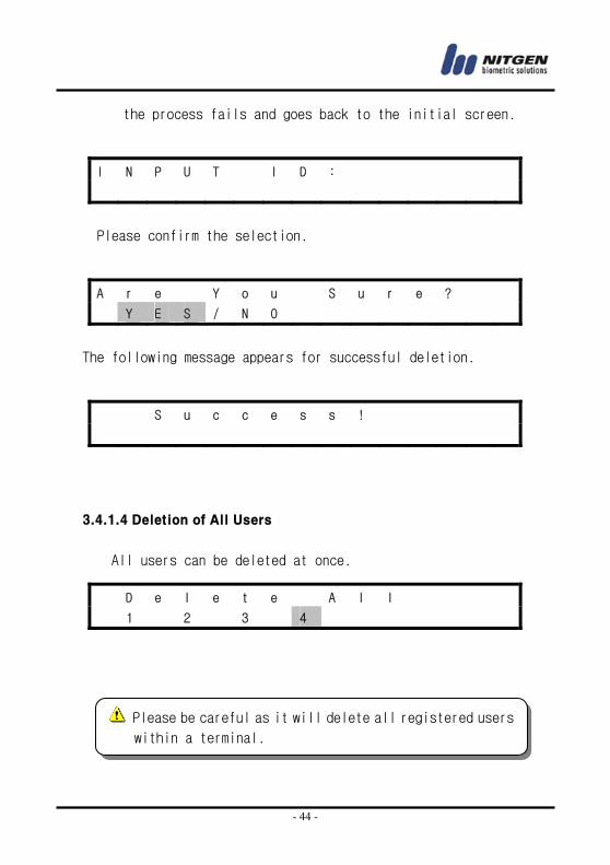
- 44 -
the process fails and goes back to the initial screen.
Please confirm the selection.
The following message appears for successful deletion.
3.4.1.4 Deletion of All Users
All users can be deleted at once.
I N P U T I D :
A r e Y o u S u r e ?
Y E S / N O
S u c c e s s !
D e l e t e A l l
1 2 3 4
Please be careful as it will delete all registered users
within a terminal.
- 45 -
When 『yes』is selected, the deleting procedure begins.
3.4.2 Fingerprint Sensor Setting
As a second option underneath the main menu, there is an option
to select fingerprint sensor. You can choose the following in the
main menu.
There are the following 7 categories within a sub menu.
3.4.2.1 Brightness
The first category is sensor brightness. It is recommended
A r e Y o u S u r e ?
Y E S / N O
S u c C e s s !
F P O p t i o n
1 2 3 4 5 6 7
F P O p t i o n
1 2 3 4 5 6 7
- 46 -
that the initial value is not changed.
3.4.2.2 Security Level
The security level will be set for 1:1 match. It is not possible
to set security level for 1:N match and when needed, only a
NITGEN after sales engineer can set the level.
Please press ENTER to go into a sub menu.
• You can set the security level for 1:1 mode by choosing 1. However, it is recommended that the value is not changed.
B r i g h t n e s s
1 2 3 4 5 6 7
B r i g h t n e s s
( 0 - 1 0 0 ) : 5 5
S e c u . L e v e l
1 2 3 4 5 6 7
S e c u . L e v e l
1

- 47 -
1 : 1 M o d e
( 1 - 9 ) : 5
S u c c e s s !
- 48 -
3.4.2.3 Capture Mode
The product provides three capture modes for fingerprint
including normal, latent and intelli. The normal mode provides
the highest speed. The latent capture is relatively slower but
can capture latent fingerprints on the surface of a sensor. The
Intelli is relatively slower in speed, yet it analyzes the
fingerprints of users to capture the optimal fingerprint image.
The initial setting is 『latent fingerprint』. Please use a
directional key and press ENTER to finish.
C a p t u r e M o d e
1 2 3 4 5 6 7
Please press ENTER to go into a sub menu.
N o r m a l / L a t e n t
/ I n t e l l i
The following message will be displayed when an appropriate
function is successfully selected.
S u c c e s s !
- 49 -
3.4.2.4 Fingerprint Input Time (1 ~ 30 seconds)
It is to set time limit for fingerprint input to a terminal.
If a fingerprint is not input within the selected time, a
failure message will be displayed to encourage a re-try.
Please press ENTER to go into a sub menu.
S e n s o r T i m e o u t
1 2 3 4 5 6 7
The values can vary between 1~30.
The default value is 『5 seconds』. Please type in an appropriate
time with number keys and press ENTER to finish.
S e n s o r T i m e o u t
( 1 - 3 0 ) : 5
S u c c e s s !
- 50 -
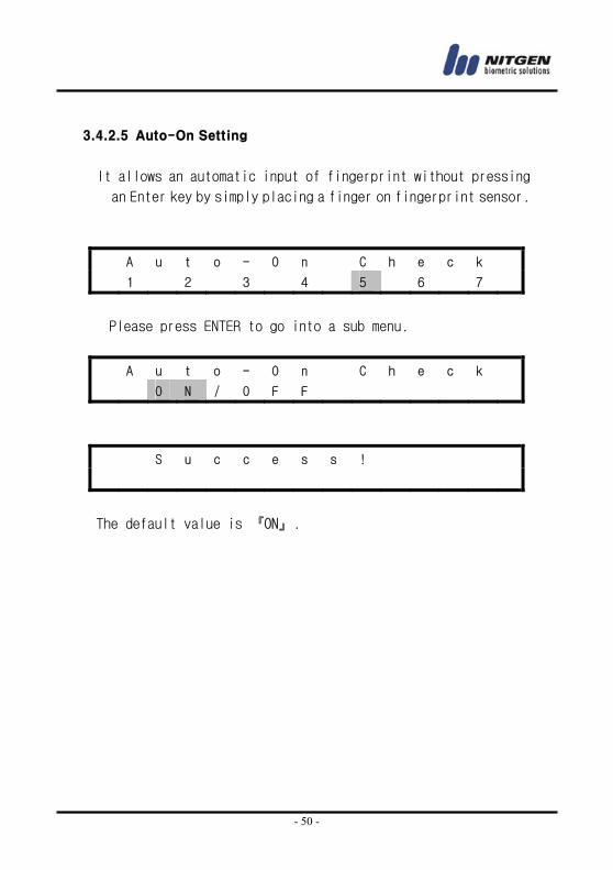
3.4.2.5 Auto-On Setting
It allows an automatic input of fingerprint without pressing
an Enter key by simply placing a finger on fingerprint sensor.
A u t o - O n C h e c k
1 2 3 4 5 6 7
Please press ENTER to go into a sub menu.
A u t o - O n C h e c k
O N / O F F
S u c c e s s !
The default value is 『ON』.
- 51 -
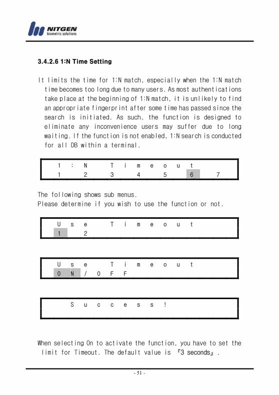
3.4.2.6 1:N Time Setting
It limits the time for 1:N match, especially when the 1:N match
time becomes too long due to many users. As most authentications
take place at the beginning of 1:N match, it is unlikely to find
an appropriate fingerprint after some time has passed since the
search is initiated. As such, the function is designed to
eliminate any inconvenience users may suffer due to long
waiting. If the function is not enabled, 1:N search is conducted
for all DB within a terminal.
1 : N T i m e o u t
1 2 3 4 5 6 7
The following shows sub menus.
Please determine if you wish to use the function or not.
U s e T i m e o u t
1 2
U s e T i m e o u t
O N / O F F
S u c c e s s !
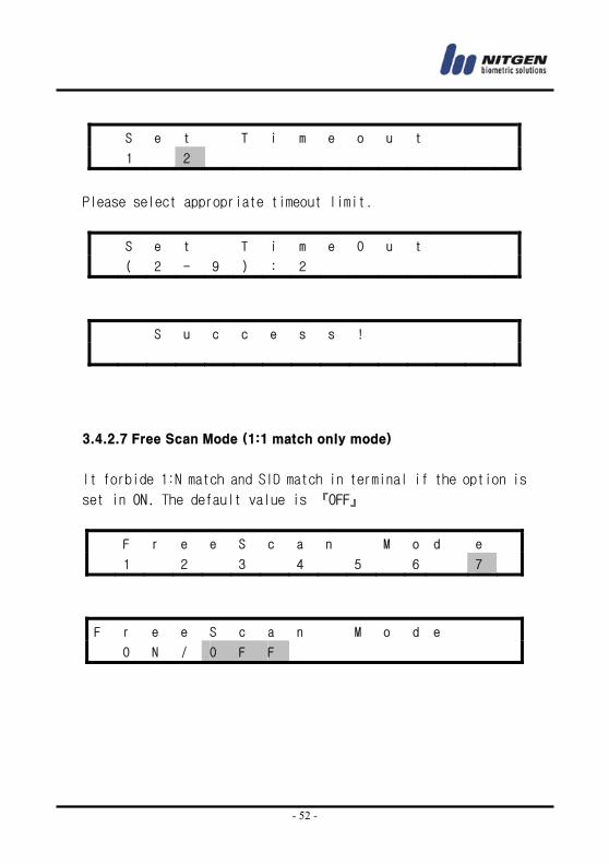
When selecting On to activate the function, you have to set the
limit for Timeout. The default value is 『3 seconds』.
- 52 -
S e t T i m e o u t
1 2
Please select appropriate timeout limit.
S e t T i m e O u t
( 2 - 9 ) : 2
S u c c e s s !
3.4.2.7 Free Scan Mode (1:1 match only mode)
It forbide 1:N match and SID match in terminal if the option is
set in ON. The default value is 『OFF』
F r e e S c a n M o d e
1 2 3 4 5 6 7
F r e e S c a n M o d e
O N / O F F
- 53 -
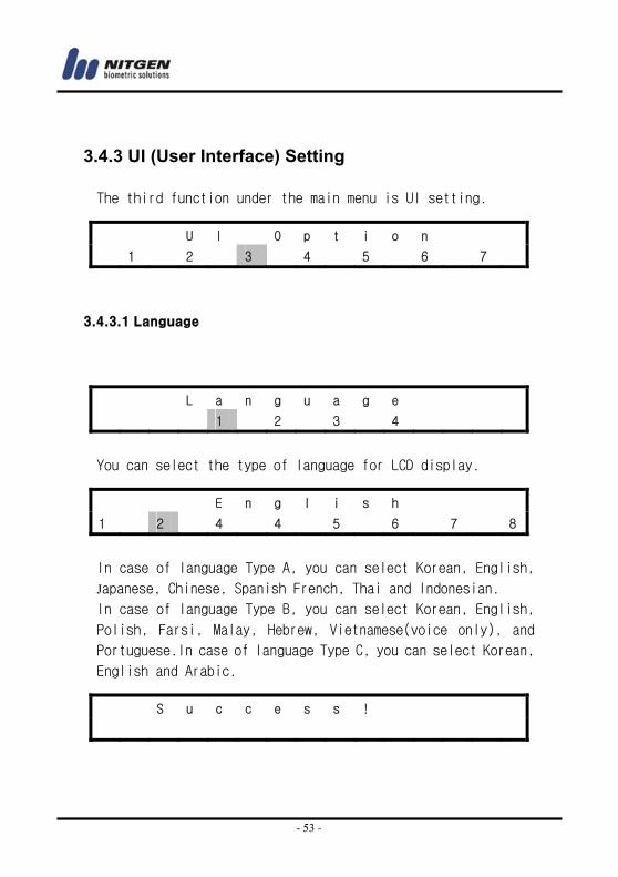
3.4.3 UI (User Interface) Setting
The third function under the main menu is UI setting.
3.4.3.1 Language
You can select the type of language for LCD display.
In case of language Type A, you can select Korean, English, Japanese, Chinese, Spanish French, Thai and Indonesian. In case of language Type B, you can select Korean, English, Polish, Farsi, Malay, Hebrew, Vietnamese(voice only), and
Portuguese.In case of language Type C, you can select Korean,
English and Arabic.
U I O p t i o n
1 2 3 4 5 6 7
L a n g u a g e
1 2 3 4
E n g l i s h
1 2 4 4 5 6 7 8
S u c c e s s !

- 54 -
3.4.3.2 Voice Guidelines
V o i c e
1 2 3 4
V o i c e
O N / O F F
S u c c e s s !
- 55 -
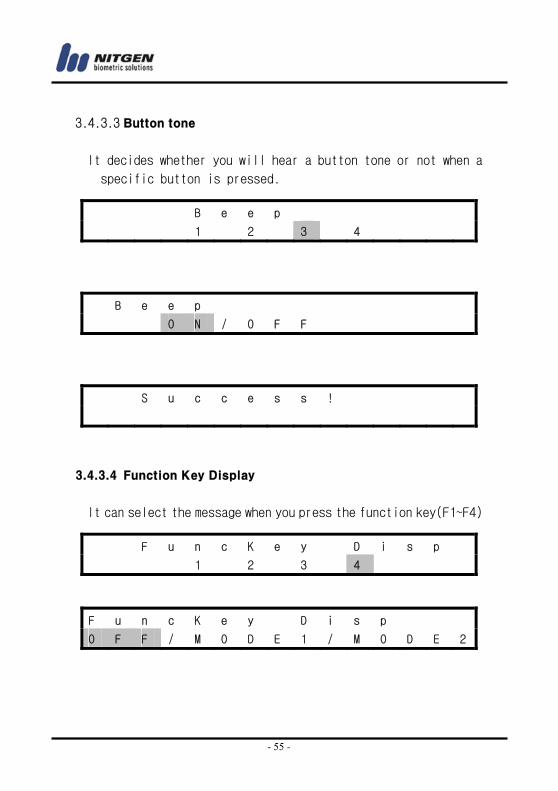
3.4.3.3 Button tone
It decides whether you will hear a button tone or not when a
specific button is pressed.
3.4.3.4 Function Key Display
It can select the message when you press the function key(F1~F4)
B e e p
1 2 3 4
B e e p
O N / O F F
S u c c e s s !
F u n c K e y D i s p
1 2 3 4
F u n c K e y D i s p
O F F / M O D E 1 / M O D E 2
- 56 -
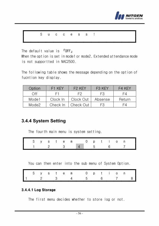
The default value is 『OFF』
When the option is set in mode1 or mode2, Extended attendance mode
is not supportted in NAC2500.
The following table shows the message depending on the option of
fucntion key display.
Option F1 KEY F2 KEY F3 KEY F4 KEY
Off F1 F2 F3 F4
Mode1 Clock In Clock Out Absense Return
Mode2 Check In Check Out F3 F4
3.4.4 System Setting
The fourth main menu is system setting.
You can then enter into the sub menu of System Option.
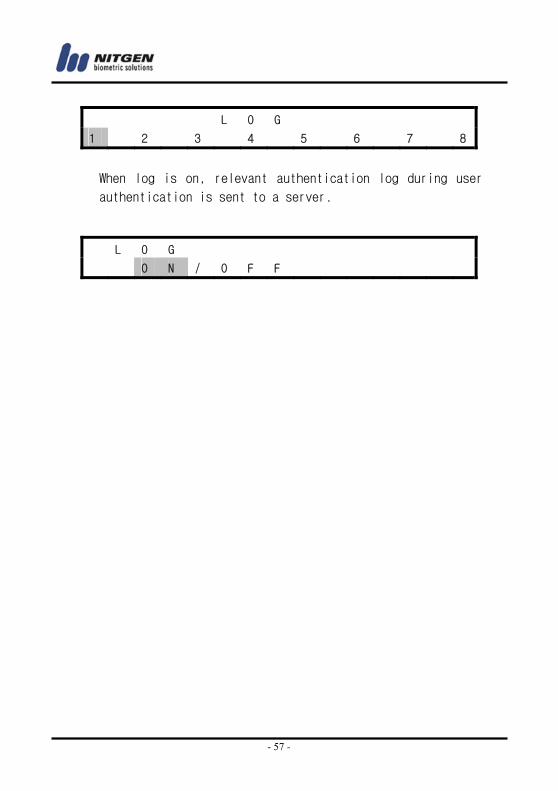
3.4.4.1 Log Storage The first menu decides whether to store log or not.
S u c c e s s !
S y s t e m O p t i o n
1 2 3 4 5 6 7
S y s t e m O p t i o n
1 2 3 4 5 6 7 8
- 57 -
When log is on, relevant authentication log during user
authentication is sent to a server.
L O G
1 2 3 4 5 6 7 8
L O G
O N / O F F
- 58 -
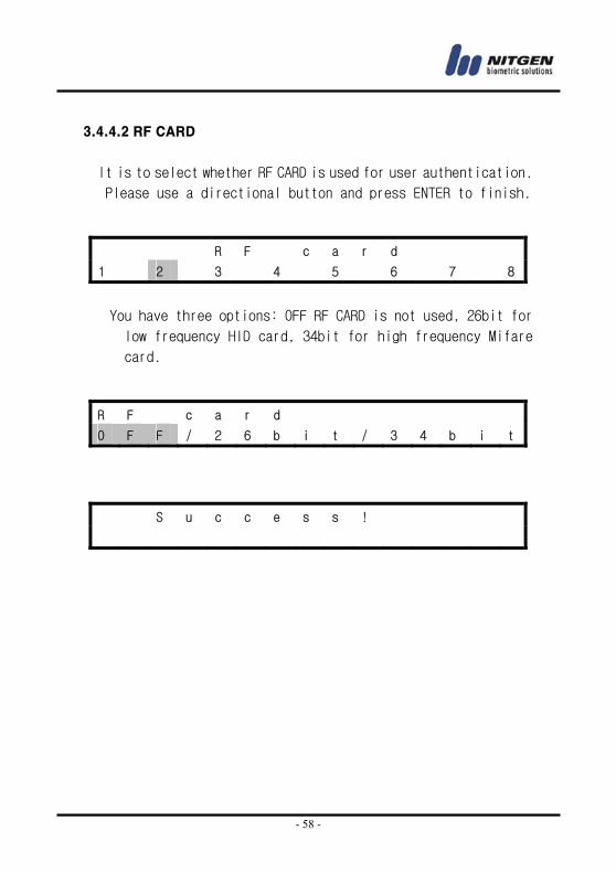
3.4.4.2 RF CARD
It is to select whether RF CARD is used for user authentication.
Please use a directional button and press ENTER to finish.
You have three options: OFF RF CARD is not used, 26bit for
low frequency HID card, 34bit for high frequency Mifare
card.
R F c a r d
1 2 3 4 5 6 7 8
R F c a r d
O F F / 2 6 b i t / 3 4 b i t
S u c c e s s !
- 59 -
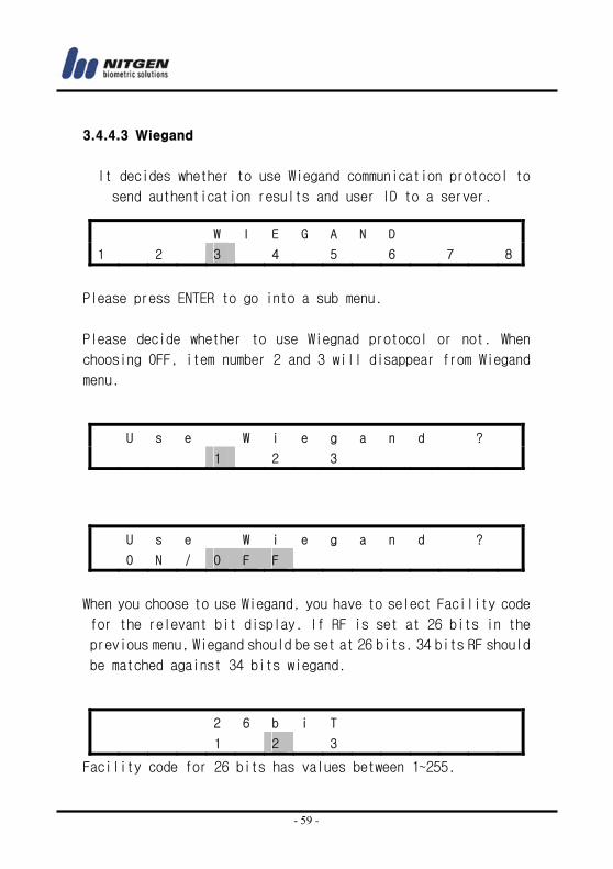
3.4.4.3 Wiegand
It decides whether to use Wiegand communication protocol to
send authentication results and user ID to a server.
Please press ENTER to go into a sub menu.
Please decide whether to use Wiegnad protocol or not. When
choosing OFF, item number 2 and 3 will disappear from Wiegand
menu.
When you choose to use Wiegand, you have to select Facility code
for the relevant bit display. If RF is set at 26 bits in the
previous menu, Wiegand should be set at 26 bits. 34 bits RF should
be matched against 34 bits wiegand.
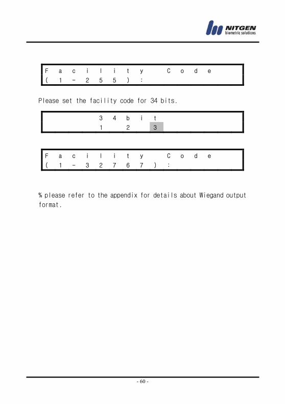
Facility code for 26 bits has values between 1~255.
W I E G A N D
1 2 3 4 5 6 7 8
U s e W i e g a n d ?
1 2 3
U s e W i e g a n d ?
O N / O F F
2 6 b i T
1 2 3
- 60 -
Please set the facility code for 34 bits.
% please refer to the appendix for details about Wiegand output
format.
F a c i l i t y C o d e
( 1 - 2 5 5 ) :
3 4 b i t
1 2 3
F a c i l i t y C o d e
( 1 - 3 2 7 6 7 ) :
- 61 -
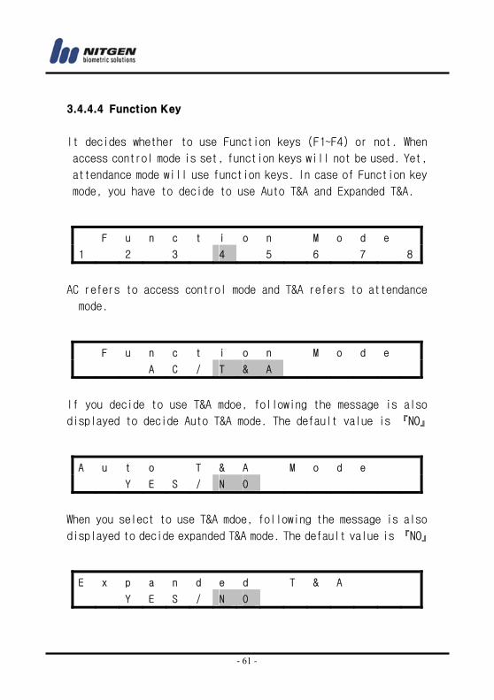
3.4.4.4 Function Key
It decides whether to use Function keys (F1~F4) or not. When
access control mode is set, function keys will not be used. Yet,
attendance mode will use function keys. In case of Function key
mode, you have to decide to use Auto T&A and Expanded T&A.
AC refers to access control mode and T&A refers to attendance
mode.
If you decide to use T&A mdoe, following the message is also
displayed to decide Auto T&A mode. The default value is 『NO』
When you select to use T&A mdoe, following the message is also
displayed to decide expanded T&A mode. The default value is 『NO』
F u n c t i o n M o d e
1 2 3 4 5 6 7 8
F u n c t i o n M o d e
A C / T & A
A u t o T & A M o d e
Y E S / N O
E x p a n d e d T & A
Y E S / N O
- 62 -
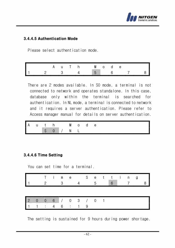
3.4.4.5 Authentication Mode
Please select authentication mode.
There are 2 modes available. In SO mode, a terminal is not
connected to network and operates standalone. In this case,
database only within the terminal is searched for
authentication. In NL mode, a terminal is connected to network
and it requires a server authentication. Please refer to
Access manager manual for details on server authentication.
3.4.4.6 Time Setting
You can set time for a terminal.
The setting is sustained for 9 hours during power shortage.
A u T h M o d e
1 2 3 4 5 6 7 8
A u t h M o d e
S O / N L
T i m e S e t t i n g
1 2 3 4 5 6 7 8
2 0 0 6 / 0 3 / 0 1
1 1 : 4 6 : 1 9
- 63 -
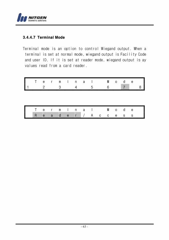
3.4.4.7 Terminal Mode
Terminal mode is an option to control Wiegand output. When a
terminal is set at normal mode, wiegand output is Facility Code
and user ID. If it is set at reader mode, wiegand output is ay
values read from a card reader.
T e r m i n a l M o d e
1 2 3 4 5 6 7 8
T e r m i n a l M o d e
R e a d e r / A c c e s s
- 64 -
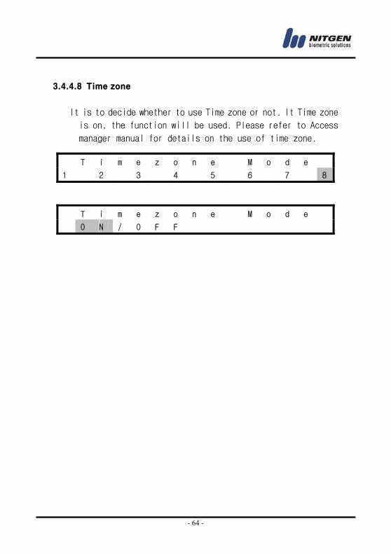
3.4.4.8 Time zone
It is to decide whether to use Time zone or not. It Time zone
is on, the function will be used. Please refer to Access
manager manual for details on the use of time zone.
T i m e z o n e M o d e
1 2 3 4 5 6 7 8
T i m e z o n e M o d e
O N / O F F
- 65 -
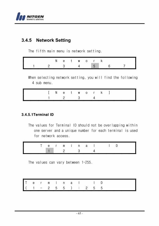
3.4.5 Network Setting
The fifth main menu is network setting.
When selecting network setting, you will find the following
4 sub menu.
3.4.5.1Terminal ID
The values for Terminal ID should not be overlapping within
one server and a unique number for each terminal is used
for network access.
The values can vary between 1~255.
N e t w o r k
1 2 3 4 5 6 7
[ N e t w o r k ]
1 2 3 4
T e r m i n a l I D
1 2 3 4
T e r m i n a l I D
( 1 - 2 5 5 ) : 2 5 5
- 66 -
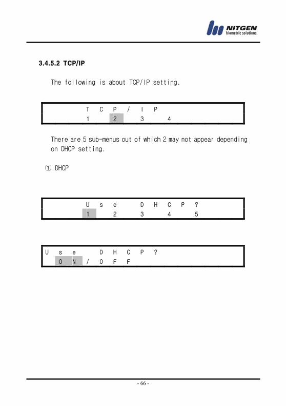
3.4.5.2 TCP/IP
The following is about TCP/IP setting.
There are 5 sub-menus out of which 2 may not appear depending
on DHCP setting.
① DHCP
T C P / I P
1 2 3 4
U s e D H C P ?
1 2 3 4 5
U s e D H C P ?
O N / O F F
- 67 -
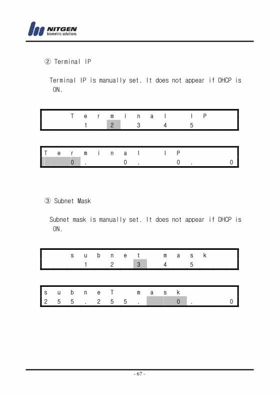
② Terminal IP
Terminal IP is manually set. It does not appear if DHCP is
ON.
③ Subnet Mask
Subnet mask is manually set. It does not appear if DHCP is
ON.
T e r m i n a l I P
1 2 3 4 5
T e r m i n a l I P
0 . 0 . 0 . 0
s u b n e t m a s k
1 2 3 4 5
s u b n e T m a s k
2 5 5 . 2 5 5 . 0 . 0
- 68 -
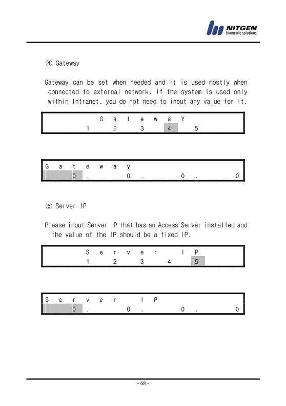
④ Gateway
Gateway can be set when needed and it is used mostly when
connected to external network. If the system is used only
within Intranet, you do not need to input any value for it.
⑤ Server IP
Please input Server IP that has an Access Server installed and
the value of the IP should be a fixed IP.
G a t e w a Y
1 2 3 4 5
G a t e w a y
0 . 0 . 0 . 0
S e r v e r I P
1 2 3 4 5
S e r v e r I P
0 . 0 . 0 . 0
- 69 -
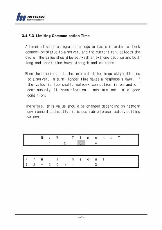
3.4.5.3 Limiting Communication Time
A terminal sends a signal on a regular basis in order to check
connection status to a server, and the current menu selects the
cycle. The value should be set with an extreme caution and both
long and short time have strength and weakness.
When the time is short, the terminal status is quickly reflected
to a server. In turn, longer time makes a response slower. If
the value is too small, network connection is on and off
continuously if communication lines are not in a good
condition.
Therefore, this value should be changed depending on network
environment and mostly, it is desirable to use factory setting
values.
N / W T i m e o u T
1 2 3 4
N / W T I m e o u T
( 2 - 2 0 ) : 3
- 70 -
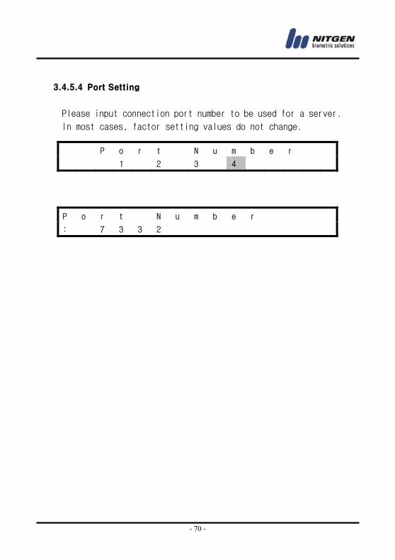
3.4.5.4 Port Setting
Please input connection port number to be used for a server.
In most cases, factor setting values do not change.
P o r t N u m b e r
1 2 3 4
P o r t N u m b e r
: 7 3 3 2
- 71 -
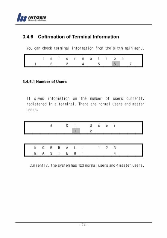
3.4.6 Cofirmation of Terminal Information
You can check terminal information from the sixth main menu.
3.4.6.1 Number of Users
It gives information on the number of users currently
registered in a terminal. There are normal users and master
users.
Currently, the system has 123 normal users and 4 master users.
I n f o r m a t i o n
1 2 3 4 5 6 7
# O f U s e r
1 2
N O R M A L : 1 2 3
M A S T E R : 4
- 72 -
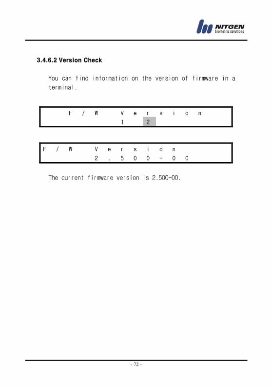
3.4.6.2 Version Check
You can find information on the version of firmware in a
terminal.
The current firmware version is 2.500-00.
F / W V e r s i o n
1 2
F / W V e r s i o n
2 . 5 0 0 - 0 0
- 73 -
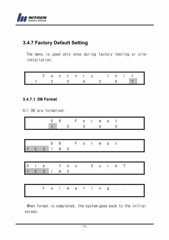
3.4.7 Factory Default Setting
The menu is used only once during factory testing or site
installation.
3.4.7.1 DB Format
All DB are formatted.
When format is completed, the system goes back to the initial
screen.
F a c t o r y I n i t
1 2 3 4 5 6 7
D B F o r m a t
1 2 3 4 5
D B F o r m a t
Y E S / N O
A r e Y o u S u r e ?
Y E S / N O
F o r m a t i n g . .
- 74 -
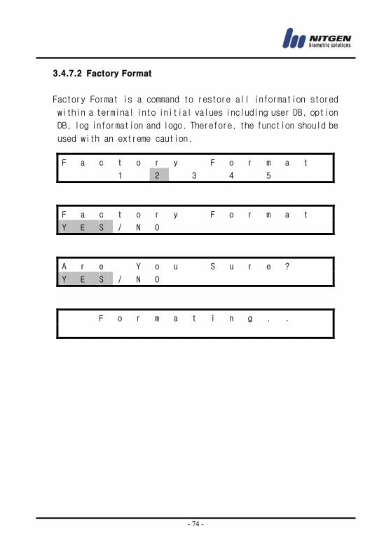
3.4.7.2 Factory Format
Factory Format is a command to restore all information stored
within a terminal into initial values including user DB, option
DB, log information and logo. Therefore, the function should be
used with an extreme caution.
F a c t o r y F o r m a t
1 2 3 4 5
F a c t o r y F o r m a t
Y E S / N O
A r e Y o u S u r e ?
Y E S / N O
F o r m a t i n g . .
- 75 -
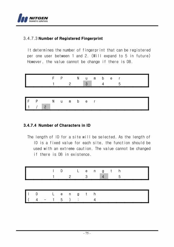
3.4.7.3 Number of Registered Fingerprint
It determines the number of fingerprint that can be registered
per one user between 1 and 2. (Will expand to 5 in future)
However, the value cannot be change if there is DB.
3.4.7.4 Number of Characters in ID
The length of ID for a site will be selected. As the length of
ID is a fixed value for each site, the function should be
used with an extreme caution. The value cannot be changed
if there is DB in existence.
F P N u m b e r
1 2 3 4 5
F P N u m b e r
1 / 2
I D L e n g t h
1 2 3 4 5
I D L e n g t h
( 4 - 1 5 ) : 4
- 76 -
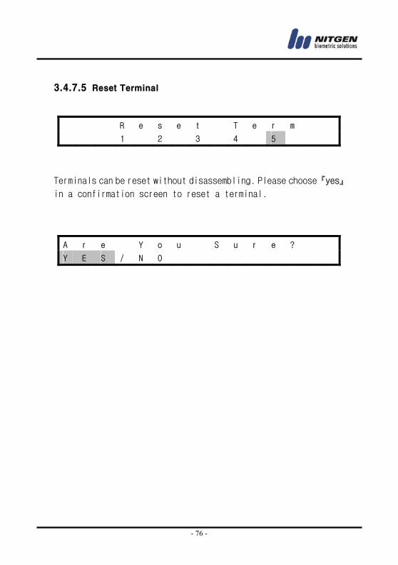
3.4.7.5 Reset Terminal
Terminals can be reset without disassembling. Please choose 『yes』
in a confirmation screen to reset a terminal.
R e s e t T e r m
1 2 3 4 5
A r e Y o u S u r e ?
Y E S / N O
- 77 -
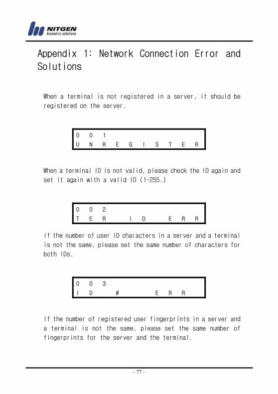
Appendix 1: Network Connection Error and
Solutions
When a terminal is not registered in a server, it should be
registered on the server.
When a terminal ID is not valid, please check the ID again and
set it again with a valid ID (1~255.)
If the number of user ID characters in a server and a terminal
is not the same, please set the same number of characters for
both IDs.
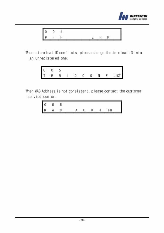
If the number of registered user fingerprints in a server and
a terminal is not the same, please set the same number of
fingerprints for the server and the terminal.
0 0 1
U N R E G I S T E R
0 0 2
T E R I D E R R
0 0 3
I D # E R R
- 78 -
When a terminal ID conflicts, please change the terminal ID into
an unregistered one.
When MAC Address is not consistent, please contact the customer
service center.
0 0 4
# F P E R R
0 0 5
T E R I D C O N F LICT
0 0 6
M A C A D D R ERR
- 79 -
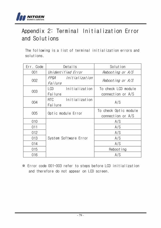
Appendix 2: Terminal Initialization Error
and Solutions
The following is a list of terminal initialization errors and
solutions.
Err. Code Details Solution
001 Unidentified Error Rebooting or A/S
002 FPGA Initialization
Failure Rebooting or A/S
003 LCD Initialization
Failure
To check LCD module
connection or A/S
004 RTC Initialization
Failure A/S
005 Optic module Error To check Optic module
connection or A/S
010 A/S
011 A/S
012 A/S
013 A/S
014 A/S
015 Rebooting
016
System Software Error
A/S
※ Error code 001~003 refer to steps before LCD initialization
and therefore do not appear on LCD screen.
- 80 -
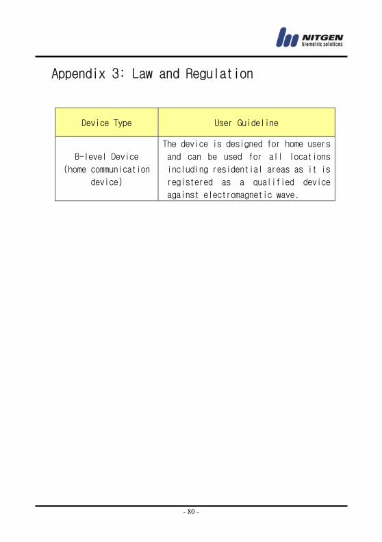
Appendix 3: Law and Regulation
Device Type User Guideline
B-level Device
(home communication
device)
The device is designed for home users
and can be used for all locations
including residential areas as it is
registered as a qualified device
against electromagnetic wave.
- 81 -
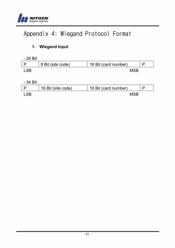
Appendix 4: Wiegand Protocol Format
1. Wiegand Input - 26 Bit P 8 Bit (site code) 16 Bit (card number) P LSB MSB - 34 Bit P 16 Bit (site code) 16 Bit (card number) P LSB MSB
- 82 -
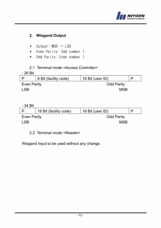
2. Wiegand Output
Output: MSB → LSB
Even Parity: Odd number 1
Odd Parity: Even number 1
2.1 Terminal mode <Access Controller> - 26 Bit P 8 Bit (facility code) 16 Bit (user ID) P Even Parity Odd Parity LSB MSB - 34 Bit P 16 Bit (facility code) 16 Bit (user ID) P Even Parity Odd Parity LSB MSB
2.2 Terminal mode <Reader>
Wiegand Input to be used without any change.
- 83 -
Appendix 5 : EMERGENCY Screen
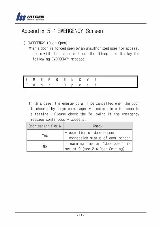
1) EMERGENCY (Door Open)
When a door is forced open by an unauthorized user for access,
doors with door sensors detect the attempt and display the
following EMERGENCY message.
In this case, the emergency will be cancelled when the door
is checked by a system manager who enters into the menu in
a terminal. Please check the following if the emergency
message continuously appears.
Door sensor Y or N Check
Yes - operation of door sensor
- connection status of door sensor
No If warning time for “door open” is
set at 0 (see 2.4 Door Setting)
E M E R G E N C Y !
D o o r O p e n !