N 0) MISTY PICTURE - Defense Technical Information Center · AFWL-TR-87-1 14 AW-R 87-114 N PHETS...
90
AFWL-TR-87-1 14 AW-R 87-114 N PHETS LIGHTNING HARDENING PROGRAM: 0) MISTY PICTURE EVENT G. P. Chapman, et al Mission Research Corporation 1720 Randolph Road, SE Albuquerque, NM 87106 June 1988 DTI ELECT JUL 1 41988 Final Report S DU Approved for public release; distribution unlimited. V AIR FORCE WEAPONS LABORATORY Air Force Systems Command Kirtland Air Force Base, NM 87117-6008
-
Upload
nguyentruc -
Category
Documents
-
view
214 -
download
1
Transcript of N 0) MISTY PICTURE - Defense Technical Information Center · AFWL-TR-87-1 14 AW-R 87-114 N PHETS...

AFWL-TR-87-1 14 AW-R87-114
N PHETS LIGHTNING HARDENING PROGRAM:0) MISTY PICTURE EVENT
G. P. Chapman, et al
Mission Research Corporation1720 Randolph Road, SEAlbuquerque, NM 87106
June 1988 DTIELECTJUL 1 41988
Final Report S DU
Approved for public release; distribution unlimited.
V AIR FORCE WEAPONS LABORATORYAir Force Systems CommandKirtland Air Force Base, NM 87117-6008

AFWL -TR-87-114
This final report was prepared by Mission Research Corporation,Albuquerque, New Mexico, under Contract F29601-85-C-0009, Job Order 672AO911,with the Air Force Weapons Laboratory, Kirtland Air Force Base, New Mexico.Mr David H. Hilland (NTAT) was the Laboratory Project Officer-in-Charge.
When Government drawings, specifications, or other data are used for anypurpose other than in connection with a definitely Government-related procure-ment, the United States Government incurs no responsibility or any obligationwhatsoever. The fact that the Government may have formulated or in any waysupplied the said drawings, specifications, or other data, is not to beregarded by implication, or otherwise in any manner construed, as licensingthe holder, or any other person or corporation; or as conveying any rights orpermission to manufacture, use, or sell any patented invention that may in anyway be related thereto.
This report has been authored by a contractor of the United StatesGovernment. Accordingly, the United States Government retains a nonexclusive,royalty-free license to publish or reproduce the material contained herein, orallow others to do so, for the United States Government purposes.
This report has been reviewed by the Public Affairs Office and isreleasable to the National Technical Information Service (NTIS). At NTIS, itwill be available to the general public, including foreign nationals.
If your address has changed, if you wish to be removed from our mailinglist, or if your organization no longer employs the addressee, please notifyAFWL/NTAT, Kirtland Air Force Base, NM 87117-6008 to help us maintain acurrent mailing list.
This report has been reviewed and is approved for publication.
iS19DAVID H. HILLANDProject Officer
FOR THE COMMANDER
KENNETH N. COLEERJCapt, USAF Lt Co UChief, Technology Br Chie aft & Missiles Div
DO NOT RETURN COPIES OF THIS REPORT UNLESS CONTRACTUAL OBLIGATIONS OR NOTICEON A SPECIFIC DOCUMENT REQUIRES THAT IT BE RETURNED. U
... ...~~UR I
.. . . .. ..

UNCLASSI FIEDSECURITY CLASSIFICATION OF THIS 3AT T ABITO
REPORT DOCUMENTATION PAGEIa. REPORT SECURITY CLASSIFICATION lb. RESTRICTIVE MARKINGS
Unclassified2a. SECURITY CLASSIFICATION AUTHORITY 3 DiSTRIBUTiON/AVAiLABILITY OF REPORT
Approved for public release; distribution
2b. DECLASSIFICATIONY DOWNGRADING SCHEDULZ unlimited.
4. PERFORMING ORGANIZATION REPORT NUMBER(S) 5. MONITORING ORGANIZATION REPORT NUMBER(S)
AMRC-R-919 AFWL-TR-87-114
6a. NAME OF PERFORMING ORGANIZATION 6b OFFICE SYMBOL 7a NAME OF MONITORING ORGANIZATION
Mission Research Corporation (if apicable) Air Force Weapons Laboratory
6c. ADDRESS (City, State, and ZIPCode) 7b ADDRESS (City, State, and ZIP Code)
1720 Randolph Road, SE Kirtland Air Force Base,Albuquerque, New Mexico 87105 New Mexico 87117-6008
Ba. NAME OF FUNDING/SPONSORING 8b. OFFICE SYMBOL 9 PROCUREMENT INSTRUMENT IDENTIFICATION NUMBERORGANIZATION (if a plicable) F 9 0 - 5 C 0 0F29601 -85-C-0009
Bc. ADDRESS (City, State, and ZIP Code) 10 SOURCE OF FUNDING NUMBERSPROGRAM PROJECT TASK WORK UNIT
ELEMENT NO. NO. INO ACCESSION NO V
64312F 672A 09 1111 TITLE (Include Security Classification)
PHETS LIGHTNING HARDENING PROGRAM- Misty Picture Event
12. PERSONAL AUTHOR(S)Chapman, G.P,; Gardner, R.L.; Lu, G.S.; Rison, W.; and Gurbaxani, S.H.
13a. TYPE OF REPORT 13b. TIME COVERED 114. DATE OF REPORT (Year, Month, Day) S. PAGE COUNTFinal FROM Jan 87 To Nov 87 1 788, June 1'92
16. SUPPLEMENTARY NOTATION G. S. LU is employed by the Defense Nuclear Agency/FCIE, KAFB, NM;W. Rison is employed by the New Mexico Institute of Mining and Technology, Socorro, NM; and_ W_ Rrhrbni il, with thp Ameriran Science Foundation. Inc., PO Box 14353, Albug. NM.
17 COSATI CODES I- . SUBJECT TERMS (Continue on reverse if necessar and identify by block number)FIELD GROUP SUB-GROUP ;Lightning; H1igh explosives04 02 Lightning protection, Instrumentation
Surge protection Sensors.[
19. ABSTRACT (Continue on reverse of necesslary and identify by block number)
-.The Permanent High Explosive Test Site (PHETS) testbed electrical topology and data floware presented along with various equipments used in the topology. Using this information,recommendations are made to harden the test~bed instrumentation to electrical transients.These transients may be caused by lightning or electrostatic discharge. Specific attention
is given to the junction box design, the shorting blocks, use of shielded cables, protectionof the sensors, and the instrumentation bunker/container. Additional attention is given tothe protection of personnel from lightning effects. Also it is recommended the optimumdesign is of a Faraday cage concept that completely encases the instrumentation from sensorto permanent recording medium. The optimum design should be prototyped and tested usingthe Precision TestLbed and current injection before general application to the PHETS.
20. DISTRIBUTION/AVAILABILITY OF ABSTRACT 21 ABSTRACT SECURITY CLASSIFICATION
C3UNCLASSIFIED/UNLIMITED MKSAME AS RPT 0DTIC USERS Unclassified22a. NAME OF RESPONSIBLE INDIVIDUAL 22b. TkLEPHONE (Include Area Code) 22c OFFICE SYMBOLDavid H. Hilland I 505) 844-9791 AFWL/NTAT
DO FORM 1473,l84 MAR 3 APR eaition may be used until exh~austed. SECURITY CLASSIFICATION OF THIS PAGEAll other editions are obsolete.
UNCLASSIFIED
. . . ' I- .pv v " .- W w '" w" ' *"- -' *< *. ' . A \A", '' \ - . " ~I Ax ,r x. '

UNCLASSIFIED111CURITY CLASUIPICAIION OPTHIws PAGE
UNCLASSIFIEDSECUMITY CLASSIFICATION OF THIS PAGE

PREFACE
The Misty Picture high explosive test and previous high explosive tests have
suffered the loss of sensors to lightning caused transients. This report is
the result of Department of Defense (DOD) efforts to determine ways to prevent Ithese losses. The information presented here comes from extensive observation
of the Misty Picture high explosive event at the northern end of White Sands
Missile Range. Additional considerations include damage or the potential for
damage due to electrostatic phenomena to all parts of the instrumentation sys-
tem, to personnel, and to expensive non essential hardware. This information
will be available to all DOD personnel and their contractors and to all
testing personnel from foreign governments.
Appreciation is due to numerous personnel of the Defense Nuclear Agency, the
White Sands Missile Range, the Air Force Weapons Laboratory, and several con-
tractors for their valuable inputs to this effort. Special appreciation is
due to Mr. David Hilland of the Air Force Weapons Laboratory for his knowl-
edgeable support of this effort.
Acce.Ito;I For
NrsC CR42DL T Aq LI
DTIC I T I-
.... .... .... .... ................
H- .. ....- ... ........ .... . .
vI "U ;0'u .
! ICOPYI
iii/iv,
-kok %krw or e- 4- or *.W 4- . r

CONTENTS
Section Page
1.0 INTRODUCTION 1
1.1 PURPOSE 11.2 BACKGROUND 11.3 OVERVIEW 4
2.0 TOPOLOGY 6
2.1 TESTBED 62.2 DATA FLOW 11
3.0 EQUIPMENT LIST 25
3.1 TRANSDUCERS 253.1.1 Pressure gages 253.1.2 Strain gages 253.1.3 Stress gages 273.1.4 Accelerometers 273.1.5 Velocity gages 273.1.6 Soil stress gages 273.1.7 Time-of-arrival crystals 273.1.8 Displacement gages 27
3.2 TRANSMISISON SYSTEM 28
3.2.1 DNA quad 283.2.2 DNA 20 pair 283.3.3 Optical fiber 283.3.4 Coaxial cable 28
3.3 DIESEL GENERATOR 28
3.4 UNINTERRUPTIBLE POWER SUPPLIES (UPS) 31
3.5 INSTRUMENTATION AMPLIFIERS 31
3.6 TRANSIENT DATA RECORDER (TDR) 32
4.0 RECOMMENDATIONS 33
4.1 SPECIFIC EXAMPLES 35
4.11 Commercial power conditioning 354.1.2 ANFO charge container 35
V

CONTENTS (Concluded)
Section Page
4.2 INSTRUMENTATION BUNKER/INSTRUMENTATION CONTAINER 36
4.3 JUNCTION BOXES 37
4.4 SHORTING BLOCKS 37
4.5 GENERIC TOPOLOGY 38
5.0 CONCLUSIONS 42
REFERENCES 44
BIBLIOGRAPHY 45
DEFINITIONS 46
APPENDIXES
A. FIELD MILL SYSTEM 49
B. EXAMPLES OF SHIELDED CABLE SPECIFICATIONS 59
C. EARTH GROUND TESTING 73
vi
-~~~~~~~~~~~~~, .S*41 ...................................
FIGURES
Figure Page
1 Location of the PHETS site. 2
2 Location of the MP test on the PHETS site. 3
3 Instrumentation bunker without berm. 7
4 West Instrumentation Park. 8
5 Administration Park. 9
6 Playback Park. 10
7 Typical data flow. 12
8 Timing and firing cable layout. 13
9 Commercial power distribution at PHETS. 15
10 Field mill signal cable layout. 16
11 Fiber optic cable layout. 17
12 Typical signal path from transducer to instrumentation bunker. 18
13 Power cable entering bunker. 20
14 Shield defeating ground wire and properly installed ground 21wi re.
15 Two equipment boxes connected by coaxial cable by three methods. 22
16 The grounding trees for independent systems showing a largeloop when trees are connected. 24
17 Typical wheatstone bridge circuit. 26
18 DNA quad cable. 29
19 DNA 20-pair cable. 30
20 A hardened analogue to Figure 12. 39
21 Wire bundle protected. by overhead ground wire. 41
vii
C-C-.'.

FIGURES (Concluded)
FigurePae
A-I Field mill theory. 49
A-2 Printer output (three locations). 51
A-3 Signal monitoring box (located in Administration trailer). 52
A-4 Field mill signal cables. 53
A-5 Field mill installation. 54
C-I 8 ft ground rod. 75
C-2 EB-5 ground well. 77
C-3 WB-2 ground well. 78
C-4 EB-5 bunker. 79
C-5 WB-2 bunker. 80
viii

1.0 INTRODUCTION
1.1 PURPOSE
The purpose of this report is to describe the Permanent High Explosive Test
Site (PHETS), its topology, its hardware, and lightning hardening and
shielding efforts. Also, recommendations are made for near-term and far-
term improvements to the test site.
1.2 BACKGROUND
The MISTY PICTURE (MP) high explosive (HE) test sponsored by the Defense
Nuclear Agency (DNA) provided the nuclear weapons effects for measuring
vulnerability and survivability of defense systems. The effects provided
were ground shock, airblast, and simulated thermal environments. The data
produced by this test enhance the knowledge of particular phenomenology and
increase and refine the effects database.
The MP HE test was conducted at White Sands Missile Range (WSMR), 41 road
miles southeast of Socorro, New Mexico and approximately 20 miles (32 km)
south of the northern boundary of WSMR (Fig. 1). The location of PHETS is
shown by Fig. 2. Ground zero (GZ) was located 500 ft southeast of the
MINOR SCALE (MS) GZ. This location allowed the reuse of nearby roads, the
instrumentation parks, the instrumentation radials, and most of the diag-
nostic camera bunkers. Because the crater of the previous test site was
meticulously filled-in and repacked, it was possible to reuse the site fnr
similar tests by moving the GZ only a nominal distance.
In previous HE tests of similar or smaller magnitude, sensors and
transducers were lost for various reasons, but the prevalent cause was
transients caused by lightning. In October 1983, 274 sensors were damaged
or destroyed in the DIRECT COURSE (DC) test. In June 1985, 135 sensors
were damaged or destroyed in the MS test. And in May 1987, 102 sensors
were damaged or destroyed in the MP test.
w ' |" 1 -k ' '- " ' ' ' ' ' F

HE TESTSOCORRO AREA
_________________________________STALLION0
RANGE PHETS
CENTER
NEW MEXICO
ALBUQUERQUE
WHITHIT SANDSSMRMISSISLEL RANGEA
SOCORRO
Figure 1. Location of the PHETS site.
2
%-

A0
BRV LAUNCH
o oAREA TRINITY SITE
00
0 McDONALD RANCH
NORTHNORTH INSTR. PARK
PARK ------ MISTY
PCUEGZ
YARD \0 EARKINT
0 4000 8000 PR
6m 1ii-WSCALE IN FEET SOUTH INSTR.0 1 2 BTH0 PARK
SCALE IN km PLAN
Figure 2. Location of the MP test on the PHETS site.
3

1.3 OVERVIEW
This report has been written in 5 sections to detail the hardening effort.
The remainder of the report is, in summary:
a. Section 2.0 - TOPOLOGY
This section describes the electrical topology of the PHETS; including the
detailed testbed, the data collection system, the special subsystems, the
individual shelters used for environmental control and any other hardware
that may contribute to the lightning threat.
b. Section 3.0 - EQUIPMENT LISTS
This section lists most of the component hardware in a linear fashion as
the data would flow from the transducer to the data recording system.
c. Section 4.0 - RECOMMENDATIONS
This section describes. the changes in procedures or hardware that are
recommended. These changes should be ones that increase hardware hardness
to electrical surges/transients, increase personnel safety, and enhance
data quality.
d. Section 5.0 - CONCLUSIONS
This section briefly discusses the value of this lightning hardening
effort.
e. LIST OF DEFINITIONS
This list gives several definitions of various terms and hardware germainto the treatment of lightning and electrostatic caused transients. Also,
included are terms that help define PHETS hardware that is either vulner-
able to damage or that may cause damage as a consequence of high current/
voltage effects.
4
f. REFERENCES AND BIBLIOGRAPHY
Many references are given that are not used in this report. This has been
done so that the reader who wishes to more thoroughly understand the theory
of lightning and its consequences may find relative documentation. Also
given are references to electromagnetic shielding.
g. APPENDICES
There are three appendices. Appendix A gives the theory and operation of
the field mill system, an extremely important system for giving lightning
potential warning 24 h/day. Appendix B gives detailed specifications on
the two most used cables in the instrumentation topology. Appendix C gives
the results and analyses of the earth grounding survey/testing; this
information consists of ground resistance and earth resistivity.
5

2.0 TOPOLOGY
2.1 TESTBED
The airblasts of tests conducted at the WSMR instrumentation parks prior to
the MS and MP tests were too strong for the standard instrumentation
trailers. As a result, two things were done for the MS and MP tests.
Eleven hardened bunkers (Fig. 3) were placed near the charge between the 3
and 10 lb/in 2 overpressure levels to allow remote digital recording of the
various sensor outputs. In addition to the hardened bunkers, there are
four instrumentation parks generally aligned with the cardinal compass
directions. At each of the parks is a bermed structure similar to a
quonset hut which houses a Recording Oscilloscope Sealed Environment System
(ROSES). (The ROSES name comes from the use of this unit at the Nevada
Test Site (NTS). This unit was used primarily as a cabling node and was Inot sealed in the NTS sense. Also, a large trailer located at the West
Instrumentation Park was used to record analog data. This trailer was
placed inside the Instrumentation Park's bermed structure (Fig. 4). The
North, South, and East Instrumentation Parks contained the ROSES only.
The recording facilities at both the bunkers and parks were unmanned and
were configured to operate remotely. The closest manned site was the old
DIRECT COURSE administration park, which was used for the MP Timing and
Firing (T&F) Park. DNA provided 1365 digital and 243 analog channels for
recording the MP experimental data. All of the digital recordings were
made at the instrumentation bunkers. Some other manned instrumentation
trailers, such as, the thermal radiation simulator (TRS) control and helium
control trailers, were also located at the T&F Park. This park is located
about 11,200 ft west of the GZ and was exposed to about 0.7 lb/in 2
overpressures.
The Administration Park of MISTY PICTURE (Fig. 5) was the same one used
for MINOR SCALE. It is located on the northeast corner of the intersection
between Route 7 and Route 20. This is northwest of MP GZ. Co-located with
the Administration Park is the Playback Park (Fig. 6). This trailer with
]6

wU 0z
I- zz<
0
zz<0
z w_
ce:I- 0
Z Z
LLL
00
:) w0
IxV),
zCce4
w
U-_
<~CLv

Rif.
ROSES
Figure 4. West Instrumentation Park.
8

CL z <
K 2 at
XV.-
<

CC
ui :-j
iSit
* LA
0 0U
4LA
LUU
U.0
II -00
z F
-J-
z a
10

its uninterruptable power supply was located on the Northeast edge of the
Administration Park (Fig. 5).
At the Playback Park, all of the digital data were collected from each of
the bunkers within minutes of the detonation at GZ. This was done by using
fiber optic links to each bunker which transmitted the digitized data from
each test channel digitizer to a VAX computer located at the Playback
Park. Note: As the PHETS matures, the Playback Park will be named the
Command and Control Center to reflect the integration of the Timing and
Firing Park into the Playback Park located on the Northeastern boundary of
the Administration Park.
2.2 DATA FLOW
Data from transducers in the testbed are transmitted through cables to
recording equipment in the instrumentation containers inside the instrumen-
tation bunkers. The analog data are converted to digital form and the
information is stored in the transient data recorder (TDR) in the instru-
mentation container. These data are then interrogated by a PDP-N-23 digi-
tal microcomputer co-located with the TDR and by a VAX 750 minicomputer
located in the Playback Park. In addition, the VAX is used to get quick
look data. Both of these systems have recording media for saving the
data. The data are then reduced to a useful form. Thus, it is seen that
there are four parts to the data acquisition system: transducers to mea-
sure the physical parameters; a transmission system (cables and signal
conditioners); recording devices; and data reduction processes. Figure 7
shows the typical data flow process.
Figure 8 shows the T&F cable layout without complete detail but is repre-
sentative of requirements. The fanout, of which there are several, pro-
vides T&F information to cameras, thermal radiation simulators, time of
arrival detonation system (TOADS), etc. The T&F system provides the data
for initiating the explosive, the start time for recorders, time codes for
recording with data, etc.
11

<uJ
<LL I-< Lwzu z d < Z (Y
z eLa<U I- a<LLLJZ u z-
z <Ix
3:
LU
-j0c
LU
UU 0<U
0WjLLJ Ix.
0 0 UJU 0
0U LU-j 0 L
<J LUu0
U LU
0 xLUY.< (
-J
w CL
12

zz(A < I-
z a.
< -L za. ww
z xI
0 L
z U (A
zz0 m-
00 , z -
C%43

.a77
Figure 9 shows the commercial power distribution layout on the testbed.
There are five substations associated with the commercial power. This sys-
tem allows distant transients, usually lightning caused, to enter the
testbed area.
Figure 10 shows the signal wiring layout for the Field Mill system. The
power for the remote Field Mill units came from surge protected commercial
power at the Administrative, North, and South Parks. Appendix A com-
pletely describes the Field Mill system and the associated warning sirens.
Figure 11 shows the fiber optic cable layout. The cable has a metal shield
for environmental protection. This system has two-way communications with
each instrumentation container. The software associated with the VAX mini
computer has the capability to interrogate the data contained within each
Instrumentation Container to include TDR setup configuration, TDR data,
recorded data, etc. The objective of this system is to get near real time
quick-look data from all the recorded experiments soon after the high
explosive detonation.
Figure 12 shows the expansion of the data flow block diagram to show the
explicit topology of a typical data channel. The usual configuration is
for several of these data channels to be interconnected in a tree struc-
ture. As long as the tree structure (i.e., no loops) is maintained there
is no additional susceptibility due to the additional channels.
Following Fig. 12, the data path starts as the signals from the transducer
bridge are sent along four wires inside a shield. This cable is called a
DNA Quad. The shield is typically not connected to the sensor. The quad
carries the signal to the junction box where other quads from other sensors
are connected to a terminal strip for connection to several 20-pair cables
that take the signals to the Bunker. A junction box is only a weather pro-
tection device and is used for a convenient disconnect point. From an
electromagnetic point of view it is entirely open. Quad shields enter the
box, further defeating any possible shielding effectiveness. The junction
box is often grounded.
14-- --- -- --

0
~ BRV LAUNCH
00 ARE TRINITY SITE0 V'
0$
PAR McDNAL RANCH
NORTN. PARKT NSA PR
SCL INONL FEETH
SCALE IN kmIPLANTPPAR
MISTY
Figue 9 Corrnrcil pwerdisribtio;atPCE.
CABL
SS SUSATO AR EAS S ,'.JIN
STLINTRINITY SITE
PMIST PICTURE 20
WES INSTRUMENTATIONOPARARK
I ADIN O T& F6.27km FILD IRLL PARK
TTIIN FIWSTRKI.8Gk
WEST~MST PKCUR TOS.K1.6k
WEST ~ ~ ES INTOEATTKR.6 MEN STOUT NTUETTO
WEST PK TO NORTH PK 2.19 km PARK
Figure 10. Field mill signal cable- layout.
16

- u.4-
zz
UU Yz 0l
z zw <
zzz L
zz
LU I -_
z
I- w
CL
U. LA .
w
vi z <J
(/</
0o coWW
4 CL
_j L.L17
< Cl ?,.. ~ 'f* ~ C. .A- p.%~ ~~~~~~~~~ <A ' A. A % 1 AA ~ ~ %' AAA

-Wwnr - - - Me
LU (A Du~j
o~LU C C
CLLU _
-z 0
Lo
z0
-"4o)
13 LI.
DU <
zo o-4-
4-
CC
z < V-)C
-" D
zI- <
C
CY
18

There are connectors on the 20-pair cable side of the junction box that
provide circumferential shielding. These cables are often disconnected and
replaced with grounding blocks to provide lightning protection. Unfortu-
nately, the grounding block interconnects all of the sensor wires on that
junction box to a 90-i ground. This interconnection allows catastrophic
failure of many of the sensors due to a lightning strike on a single
sensor,
As the 20-pair cables continue, the entire cable, including ground wires,
enters the bunker, thus defeating the shield there. That shield is further
defeated by the power cable, including its neutral and ground wires entry
into the bunker. This is shown in Fig. 13. Figure 13 is an example of a
particularly bad grounding practice called a shield defeating ground wire.
(Ref. 1). This type of wire, shown schematically in Fig. 14a, effectively
turns the shield inside out, allowing currents that would flow normally on
the exterior of the shield to flow into its interior. This type of wiring,
which occurs throughout the test site, should be replaced by the more
effective concept of a completely enclosed shield Fig. 14b (Ref. 1).
Another type of protection used at PHETS is the termination of a shield
before it enters an electronics box to prevent ground loops. This is not a
good practice. Examining the three diagrams in Fig. 15 shows why this is
not good practice. In Figure 15a, there is a ground loop formed by the A
cable shield and ground. However, the currents generated flow only on the
shield. The only currents transferred to the loads are those transferred
through the cable shield. In Figure 15b, the circumferential bonds have
been replaced by pigtails as a labor saving device. There are two circuits
in this case (Fig. 15b). The first circuit is the loop formed by the cen-
ter conductor, two loads and a ground. The second circuit is the shield,
the inductors (which are the pigtails), and a ground wire. At early times,
the pigtail inductance is large and there is very little current in the 0
shield; it flows in the load circuit. As the load impedance dominates, the
current begins to flow in the shield (where it should). In other words, an
early time spike is generated in the loads because of the pigtail.
19
.' W V

Z d
CO
I-
z
I-j
z w
LCC
20.

.
u SHIELD EXTERIOR
EQUIPMENT BOXGROUNDED TO
SHIELD INTERIOR
(a). Ground wire defeating shield.
(b). Proper installation (shield not broken).
Figure 14. Shield defeating ground wire and properly installed ground wire.
21

EQUIPMENT CIRCUMFERENTIAL BOND EQUIPMENTBOX BOX
r FFL I ILEAD GROUND PLANE
(a). Proper installation of coaxial cable between two grounded equipment boxes.
EQUIPMENT EQUIPMENTBOX ? PIGTAIL PIGTAIL BOX
f,50171 5 0-4
LEAD ELEAGROUND PLANE
(b). Replacement of the circumferential bonds shown In "a" with plgtails.
EQUIEQENTMBOXBOXPEN- 7 OPEN PIGTAILBO
LEAD FLEA
(c). Remtoval of one pigtail to prevent ground loops.
Figure 15. Two equipment boxes connected by coaxial cable by three methods.
22
- - -----'- . *q % .

Finally, one of the pigtails has been removed, effectively preventing the
current to flow from the shield and forcing it into the loads inside the
boxes. This configuration effectively defeats the shield. The practice of
terminating shields early and leaving the signal wires bare, even for a
short distance, should be stopped at PHETS and replaced with a complete,
integrated shield.
Finally, there are two large grounding systems within PHETS, the data flow
system and the T&F system. These two systems are shown conceptually in
Fig. 16. While the intent is to keep these two systems separate, they can
be inadvertently combined into one or more kilometer sized loops. This can
be done by locally grounding a sensor and by grounding the local T&F sig-
nal. If two experimenters do this once there is a problem. If only one
experimenter does it once, there is not likely to be a problem because of
the large ground impedance. It is recognized that there is an attempt to
minimize this problem by using isolation transformers in the T&F system.
23
I

z
vi0
0
0 S
L.
24U

3.0 EQUIPMENT LIST
3.1 TRANSDUCERS
Transducers or gages are used to sense the physical environment, convert
that sense to an electrical signal, and to send that signal to a recording
device. There are several types of transducers used at PHETS:
" Pressure gages
" Strain gages
• Stress gages
• Accelerometers
" Velocity gages
" Soil stress gages
" Time-of-arrival (TOA) crystals
• Displacement gages
Nearly all of these transducers use a typical wheatstbne bridge circuit
(Fig. 17).
3.1.1 Pressure gages--The pressure gages include: bar gages, kulite/
endevco gages, the internally strain-gaged(ISG) kilobar stress sensors, and
column-based airblast (CBA) gages. The bar gage is useful for pressures at
or above 15 k/in 2 (103 MPa). The combined kulite and endevco gages form
the kulite/endevco integrated sensor transducer. They are used to measure tran-
sient air pressure in the range of 2 to 50,000 lb/in 2 (14 to 345,000 MPa).
The ISG is a rugged, low-sensitivity, high-range transducer designed for
direct-coupled measurement of shock stresses of 0 to 10 kbars (0 to
1,000 MPa). The CBA operates on the principle of elastic compression of a
column and is used to measure airblast pressures of over 87 k/in 2 (600 MPa)
in the free field.
3.1.2 Strain gages--The strain gages used are the steel strain gages and
the concrete strain gages. Both gages are active gages and are based on
25

S.-
C.,1T(jLLw
26I
%.TM NINO
principle that the resistance of the gage changes in direct proportion to
the change in strain level. Steel strain gages are designed for use on
reinforcing bars and steel plates. Concrete strain gages may be used to
measure strains within concrete members.
3.1.3 Stress gages--The stress gages are: the WAN Gage, the NS Gage, the
triaxial interface pressure gage to measure both normal and shear stress.
All of these measure normal stress at the structure/soil interface and are
embedded in concrete structures. Both WAM and NS gages utilize a strain
gage on the sensitive element.
3.1.4 Accelerometers--The Endevco free field or structural accelerometers
use an internal strain-gaged sensing element to measure acceleration
motions. They are set in epoxy or in aluminum canisters for free-field
placement or on mounting blocks for structural measurements.
3.1.5 Velocity gages--The velocity gages include two models of the
variable reluctance velocity gage and the mutual inductance particle velo-
cimeter (MIPV) gage. These are variable reluctance, pendulum-type trans-
ducers that measure uniaxial velocity from 0 to 1,000 ft/s (0 to 305 m/s).
3.1.6 Soil Stress gages--The soil stress gages include: the low range
sensing elements (SE) gage, the high range (HRSE) gage, the column-based
soil stress (CBS) gage, and the flatpack gage.
3.1.7 Time-of-arrival crystals--These include piezoelectric crystals which
provide shock wave time-of-arrival data. They provide termination voltage S
to TOADS channels.
3.1.8 Displacement gages--These gages include the linear variable
differential transformer (LVDT) and the celesco pull wire gages. The LVDT 0
gages measure linear displacement up to 5 in (127 mm). Typically, this N.includes relative structural motions and strain measurements in structural
members. The celesco pull wire gage is a pull wire potentiometer; i.e. a
clock spring-loaded yo-yo with an electrical output. It is used to measure
27
LA..'e
the linear distance between any points initially separated by more than 6
in (150 mm) and where relative movement includes significant lateral
components.
3.2 TRANSMISSION SYSTEM
3.2.1 DNA quad shielded cable --The four-conductor, No. 22 American Wire
Gage (AWG), shielded cable was the single most used cable in the MISTY
PICTURE test (Fig. 18). During the MP test there were no DNA approved or
furnished connectors for this cable. The experimenter provided terminal
hardware if it was required. Downstream from the transducer the quad was
always attached to a terminal strip either in a junction box or in the
instrumentation bunker. See Appendix B for quad detailed specification.
3.2.2 DNA 20-pair shielded cables--The 20-pair, No. 22 AWG shielded cable
(Fig. 19) was most often used in the MP test to connect junction boxes to
the instrumentation bunker (Fig. 7). When the junction box was not used,
the quad cable was run to a terminal strip on the outside wall of the
instrumentation container.
3.2.3 Fiber optics cable--A bundle of eight fibers within a steel jacket
was used for two-way communication and data delivery between the Playback
Park and the instrumentation bunker.
3.2.4 Coaxial cable--The RG-II/U, RG-213, and RG-58/Li coaxial cables were
used for various subsystems.
3.3 DIESEL GENERATOR
An ONAN (a division of Studebaker) 60 kw, model SF-60-MD/CIED diesel
generator provided the needed power. The generator operates either at
120-208 or 240-416 V, 104 or 280 A, and 50-60 Hz.
28
* . V-"

z zpaa
zz
40:
29

0-4 z0
-o
0-1~
4:4
-44
Zw
4:4
30

3.4 UNINTERRUPTIBLE POWER SUPPLIES (UPS)
The RTE Deltec 7000 Series uninterruptible power system used in the
instrumentation containers consists of a rectifier/battery charger, a
DC-to-AC static inverter, a static transfer switch, and a system status
display panel. When combined with a battery reservoir, the unit will pro-
tect the critical load against power outages and low line voltage for the
duration of the battery discharge time. In addition, the UPS provides
electrical isolation from the primary AC source to help reduce the effects
of electrical noise.
The Powerbase 1000 built by Solidstate Controls, Inc., is a 3.0 kVA,
3-phase uninterruptible power system used at the Playback park. The system
contains a rectifier, static inverter, battery charger and batteries. It
conditions the quality of AC power to the equipment, thus protecting
against line voltage and frequency problems. Upon power failure or tran-
sient, the batteries supply DC power to the inverter and the inverter con-
verts this DC power to AC power. This sequence occurs without any power
interruption to protected equipment and will continue until utility power
is restored or until the protected batteries are exhausted (15 min of bat-
tery life is available at full load).
3.5 INSTRUMENTATION AMPLIFIERS
The Pacific Instruments, Incorporated Modei 8656 transducer conditioning
amplifier is installed in-line in data channels entering the instru-
mentation containers. The Model 8658 signal conditioning amplifier pro-
vides excitation, conditioning, balance, calibration, amplification, and
filtering for strain gages and one, two, or four arm resistive trans-
ducers. The model 8658 is also useful with potentiometric transducers,
thermocouples, and other low level signal sources. Each channel is a -
plug-in module with front panel controls for gain, balance, and exci-
tation. Monitor jacks are installed for measuring amplifier output and
excitation. A light emitting diode (LED) indicator allows transducer
balance without external instrumentation. S
31
The Ectron Model 753A signal conditioner/amplifier is an AC line powered
plug-in unit containing a high performance differential DC amplifier,
active filter, and signal conditioning functions which include constant
voltage or constant current transducer excitation, and balance and cali-
bration with a front panel plug-in conditioner subassembly. All modules
install from the front of the enclosure. Each channel is configurable to
changing input requirements; one, two, and four arm bridge circuits, as
well as potentiometers. This model has individually isolated, regulated
and adjustable constant voltage/constant current transducer excitation. On
the front panel are mounted monitor jacks for excitation and amplifier out-
put. Bridge completion, balance and calibration resistors are mounted on a
separate front panel removable plug-in subassembly. The Model 753A was
specifically designed to accurately process low level signals in elec-
trically noisy environments by providing excellent common mode rejection
and EMI immunity.
3.6 TRANSIENT DATA RECORDER
The Pacific Instruments, Incorporated Model 9822-2189 transient data
recorder is designed to condition, sample, digitize and store in nonvol-
atile complementary metal-oxide semiconductor (CMOS) memory, high-speed
analog data. Data acquisition, recording and playback control functions
are bus-structured for direct interface to a digital computer. Ten chan-
nels mount in a 7-in high rack enclosure which is line-powered and includes
interface logic. The TDR consists of a sample-and-hold amplifier, 12 bit
analog-to digital converter, control logic and 64K words of CMOS memory
(memory is expandable to 128K). It digitizes an analog signal at a pro-
grammed sample rate and stores each sample in successive locations in
memory. The memory includes battery back-up to retain data in the event of
power loss.
32
I

4.0 RECOMMENDATIONS
A lightning protection system can be designed to protect against a direct
strike and/or against effects or currents induced in the system by the
fields produced by a nearby lightning strike. Complete protection against
direct strikes requires enclosing the total test area in a conductive
enclosure or Faraday cage. This is impossible for the overall PHETS area.
For volumes of much smaller size, special penetration protection is
required. For example, power filters for the electrical power penetrations
of the instrumentation bunkers.
Therefore, the feasible protection system for PHETS should protect items of
high value from direct strikes by diverting the surge current away from the
high value items (including personnel) to earth ground and by shielding
nearby items from transients. This type of protection should be provided
for all of the parks, the explosive container, the instrumentation bunkers,
the transducers (to the extent possible), and the interconnecting cabling.
When the explosive is in place; i.e., as soon as the ammonium nitrate and
fuel oil (ANFO) is being mixed and delivered to the ground zero container,
personnel should be evacuated to safe areas during potentially hazardous
conditions. The field mill system and visual observation are essential in
making the evacuation decision.
The instrumentation system consists of essentially three parts: (1)
sensors/transducers which produce the desired electronic signals, (2) the
digitizing/recording instrumentation, and (3) the interconnecting cables.
The following are some considerations when designing a lightning protection
scheme.
Conducting loops must be avoided, since magnetic induction will cause
currents to flow through such loops. Ideally, all parts of the system
should be designed so there are no potential differences which could cause
arcing. This is practically impossible for the PHETS because of the long
33
WVUJ

cable runs between instruments, but there are good engineering practices
and designs which can reduce vulnerability. The use of voltage limiting
devices will limit transients to harmless levels.
The bermed instrumentation bunkers containing the instrumentation
containers are ideally designed for protecting personnel but, because of
the various conductive penetrations, are not sufficiently protective of the
instrumentation (Ref. 2). Obvious efforts have been made to enhance the
bunkers' protective design by using waveguides for instrumentation cabling
coming into the bunkers and minimizing air flow and personnel openings.
Fortunately, much of this is done to protect against blast but has the
synergistic effect of improving the Faraday cage effect.
To utilize the advantage of the waveguides it will be necessary to
circumferentially bond the incoming data cable shields to the waveguide. A
point of interest here is the practice of using the quad cable shield for
the guard into the amplifiers and, hence, negating the ability to use the
shield for lightning protection. The use of a five conductor cable in
place of the quad is a possible solution to this problem. An alternative
is to filter each signal wire at its point of entry into the bunker and to
provide electrical surge arresters. Additionally, the electrical power
line should be filtered at its point of entry into the bunker and electri-
cal surge arresters should be provided. If this is done, then all of the
protection for the diesel generator will be against blast and shock only
since the incoming power line will be no different (electrically) than a
commercial power source. Once these practices are put in place, it is
essential they not be circumvented by unprotected penetrations, such as,
unfiltered radio and telephone lines.
For the instrumentation parks, the current practice of using isolation
transformers and motor generators for utility and instrumentation power is
satisfactory. The shortcoming at the instrumentation parks is the use of
unconditioned power for trailers and other nontest related items, i.e.,
those items used in preparation for the test but removed or disconnected
prior to the test. These items should have individual circuit protection
to prevent damage during the pretest period.
34
- * - i .-. - -- !- = ! ] . i " t ' , -

4.1 SPECIFIC EXAMPLES
4.1.1 Commercial Power Conditioning--There were several incidents of
lightning induced transients coming through the commercial power system.
These transients damaged individual microcomputers, a weather video moni-
tor, telephones, the Field Mill sensor units, the Field Mill monitor/relay
/computer system, and possibly other unreported equipment. The Field Mill
system was modified to include power conditioning and surge arresters. This
corrective action was taken two weeks prior to the MISTY PICTURE test, and
no more problems occurred.
All equipment using raw commercial power should be protected by surge
arresters. This includes all experiments and experimenters using com-
puters, data reduction systems, test equipment, etc., anywhere on the test
site. This is especially applicable to the Administrative Park where all
experimenters have assigned space. The preferred solution is that all of
the power used in the Administrative Park be conditioned power. The tele-
phone system should have appropriate surge protection.
4.1.2 ANFO Charge Container--The charge container for MISTY PICUTRE was
protected by a lightning protection system. This system was madeup of a
top-mounted lightning arrester connected to 12 down conductors which, in
turn, were connected to a counterpoise laidout circumferentially around the
base of the hemispheric charge container and attached to 12 equally spaced,
8-ft-long earth ground rods.
Good practice requires that the earth ground rods, counterpoise, and down -
conductors be placed at least 6 ft from the protected item, (Ref. 3). In
this case, it should be at least 6 ft from the charge container's outer
wall. This distance was experimentally arrived at to minimize the chance
of arcing from the grounding system to some conductor on the container wall
or inside the container. Upon observation of the ANFO filling procedure,
it appeared the trucks were able to stand-off more than 6 ft during the
loading process.
35

There were three systems installed on or in the charge container that
caused concern. The most worrisome of these was the detonation cord
(detcord) that ran from the booster at tije center-base of the hemisphere to
the outer wall of the container. Four detcords were spaced equally around
the circumference of the hemisphere. For mechanical protection each of the
four detcords had an aluminum shield. Prior to filling the container with
explosive, the four detcords were put in place with several feet of the
detcord coiled and taped to the container's outer wall.
The TOADS system was a second cause of concern. This system requires an
array of wires imbedded within the ANFO mixture and has piezoelectric
crystals spaced along the wires. This system is not directly wired to the
booster, but comes very close to the booster.
The third system of concern was the stress/strain gages installed on the
wall of the charge container. This system was used to measure the pres-
sures on the container wall by the ANFO and is probably the least dangerous
of the three concerns.
A nonconducting detcord should be used. Wherever any conductor penetrates
the container wall, there should be a down-conductor screen that directs
any lightning caused current to earth ground with minimum surge
impedance/potential buildup.
4.2 INSTRUMENTATION BUNKER/INSTRUMENTATION CONTAINER
The existing installed configuration provides a large conducting shield
with waveguide tubes for the signal line entry, personnel entry and pres-
surization equalization (Figs. 3 and 13). The lower ventilation pipe is
also designed as a waveguide, but its purpose as a waveguide is defeated by
the diesel generator power line passing through it (Fig. 13). The upper
ventilation pipe is of much shorter length, but it is estimated that it
provides a satisfactory waveguide cutoff.
36
- AM A .

The shield topology should be completed by terminating ground wires on the
outside of the bunker, the closing of unnecessary penetrations, and the use
o. filters. The power cable should be brought into the bunker through a
power filter and this should eliminate the noise now transmitted to the
instrumentation container. (The instrumentation container is used for
environmental control and provides no electrical isolation as it is
grounded at four places to the bunker.) This would then permit proper
grounding of the instrumentation to the interior of the bunker to eliminate
shock hazards.
4.3 JUNCTION BOXES
The junction-box (J-Box) design contributes to noise and lightning
susceptibility. The J-Boxes should be designed so they are Faraday cages
and provide a shunt for currents on cable shields around the interior of
the J-Box. Circumferential grounding at the box should be used to maintain
shield integrity and no ground wires should be allowed to penetrate the
J-Box. Surge protection could be included in the J-Boxes to protect sen-
sors. The ideal location for surge protection is nearer the sensor than
several hundreds of feet away at the J-box location, but with the J-Box
under Field Command control, the capability to protect all but the sensor
that is struck is much greater. Also, this allows a more compact design
for the protective equipment.
4.4 SHORTING BLOCKS
Shorting blocks have been used for lightning protection, but they have the
disadvantage of coupling the transients from one or a few sensors to all
other sensors sharing the same shorting block. This probably will occur
because the typical earth ground using an 8-ft-long grounding rod has
approximately 90-a resistance and the threat level currents are not shorted
to ground as intended. Until now, the best protection has been simply to
disconnect the sensor when there is a lightning threat or when no work is
being performed. This technique certinly works in most instances but is
labor intensive and time critical.
37
The disconnect process certainly does protect the sensor but is of little
use if the sensor is buried or is hardwired to the J-Box or even to the
instrumentation bunker as is often the case within 10 days to 2 weeks prior
to the test date. Also, even if the sensors are able to be disconnected,
there may be more than can be reasonably disconnected in the warning time
allowed for a fast moving thunderstorm.
The best solution is the appropriately designed J-Box coupled with
appropriate transient protection which will eliminate the need for the dis-
connects. This will be to the advantage of the experimenters since they
will have much less handling of the sensor wiring causing broken wires and
connectors and sometimes safety problems.
The shorting block's best use is to discharge static buildup on cables that
have not been used for several hours, e.g., overnight.
4.5 GENERIC TOPOLOGY
The most important recommendation for the grounding and shielding effort is
that of maintaining a layered topology approach to shielding. This is more
important then transient protection, but both may be included to enhance
lightning protection. Figure 20 shows a hardened equivalent of the the
sensor to bunker topology diagram in Fig. 12. As noted, the entire
exterior is a continuous shield, except for particular penetrations. Small
openings in the bunker will not cause difficulty if there are no cables
running through them.
The first opening is at the transducer itself. The shield is not connected
to the sensor at this point. Transient protection is recommended as near
the sensor as possible. In this version of the hardened system an addi-
tional wire has been added to the quad, making it a five conductor shielded
cable. The reason for the additional wire is to provide an additional
reference or neutral wire for the amplifiers. Since this wire is appar-
ently required inside the bunker, it must be treated as a signal wire, not
a shield as has been done in the past.
38

LJLJ
00
zz
z M0< CL
0. 0 U.01 0 ca-
0< u%
0 0)
0 z <zC0 0~ 0'
0. LL
0CL CO
0< LU
z~~ U--<LU
UJ U
CC\
0 CC.
LUUSji - Jp
0
0U aI -a U L
0 a. V)UU
uLL
= 0I
z 39

The junction box becomes a completely sealed system rather than the open
structure it is now. Designs have been examined by MRC for junction boxes
with varying degrees of transient protection built into the junction box.
How much of this is necessary can only be determined by testing.
The 20-pair cables are now complete cables with connectors on both ends.
The shield is then properly connected to the bunker and junction box. Note
that this configuration is similar to Fig. 20. Loops should be minimized
by tying bundles together to minimize field coupling and overhead ground
wires should be used to protect cables from direct strikes. This last can
be shown in Fig. 21, and is used by power companies and the New Mexico
Institute of Mining and Technology at their lightning facility to protect
from direct strikes.
The bunker itself is also hardened to prevent noise or large currents from
entering. The power cable now enters through a commercial power filter,
rather than entering through the vent. Nothing now blocks the vent. Fiber
optic cable shields are terminated the same way as cable shields. In par-
ticular, cable shields remain integral with the exterior shield as they
should.
Mission Research Corporation recommends that a complete hardened system be
constructed in prototype form and in accordancp with these practices. It
may be most efficient to do this in concert with the Precision Test Bed,
but the prototype should be as complete as possible, including hardening
the bunker. Complete current injection testing must be accomplished to
assure some coupling mode has not been overlooked.
40

E~ OVERHEAD BARE WIREABOUT 2 BUNDLE
DIAMETERSABOVE THE BUNDLE
O000 0 0 TIED BUNDLE
00
Figure 21. Wire bundle protected by overhead ground wire.
41

5.0 CONCLUSIONS
Personnel safety is paramount and above all other concerns. In the past no
personnel have been injured by lightning caused effects, but one time is
too many. To this end the greatest potential for widespread injury and
damage lies with the explosive container. Proper grounding with minimum
standoff distances to prevent arching have been presented in this report
and previous reports. Also, recommendations have been made to reduce the
danger by using less conductive or nonconductivc detcord shielding.
For all other- areas of concern to personnel and equipment safety, the field
mill system correlated with visual observations is an excellent way to give
warning to personnel. The personnel take any preplanned equipment pro-
tection action and then evacuate the danger zone.
For facilities such as the Administrative Park, Playback Park, T&F Park,
etc., personnel safety is best served by an overhead matrix of conductive
wires. This technique is especially protective to individuals in the open
between trailers.
For equipment protection in the trailer areas, it is necessary to protect
against conductive transients. This type of protection is done with var-
ious surge and shunting schemes/hardware as presented in this report and in
the references. Items to be protected include: microcomputers, tele-
phones, support hardware, etc. This type of protection is essential to
equipments connected to the commercial power system.
A facsimile of the data system starting with the sensor and flowing back to
the instrumentation containers should be tested in the precision testbed.
Additionally, some direct injection testing of the cables, junction boxes,
ports-of-entry, etc. should be done, and the instrumentation bunker
shielding should be tested (with penetrations installed) to determine what
frequencies are attenuated and to what magnitude they are attenuated.
42

The ultimate protection of equipment and personnel within, where
applicable, is the Faraday cage topology referred to and described in this
report. Where this concept is not reasonable then techniques such as dis-
connecting various sections of the system during threat periods, the use of
overhead neutrals, the use transient overflow devices, avoiding conductive
loops and inductive alignments, etc. must be practiced.
Finally, all personnel must be informed and trained to follow proper
procedures and to recognize the compromising designs and situations to be
avoided.
43
b
43
SP . 'Ifw

REFERENCES
1. Lee, K. S. H., ed., EMP Interaction: Principles, Techniques and Refer-ence Data, Hemisphere Publishing Company, 1986 (Revised).
2. Rison, W., Lightning Warning and Protection for DNA High Explosive TestBed, Mission Research Corporation, AMRC-R-794, Albuquerque, N. M.,March 1986.
3. Military Handbook - Grounding, Bonding and Shielding, for ElectronicEquipments and Facilities, Department of Defense, MIL-HDBK-419, 21April 1986.
I
J
44]-
" t.

BIBLIOGRAPHY
A Manual on Ground Resistance Testing for Users of "Megger" Ground
Testers, James G. Biddle Co., Philadelphia, PA., 1947.
Chalmers, J. A., Atmospheric Electricity, 2nd Edition, Pergamon Press,New York, 1967.,
Chapman, G., et al., USAF Handbook for the Design and Construction ofHEMP/Tempest Shielded Facilities, Mission Research Corporation, AMRC-R-739, Albuquerque, N. M., December 1986.
Feynman, R. P. et al., The Feynman Lectures of Physics, Addison-WesleyPublishing Company, Reading, Massachusetts, 1964.
Gardner, R. L., et al., Preliminary Applications of Lightning HardeningTechniques to PHETS, Mission Research Corporation, AMRC-R-876,Albuquerque, N. M., May 1987.
Gardner, R. L., Program Plan and Schedule for Subtask 03-04/00, PHETSLightning Hardening Program, Mission Research Corporation, AMRC-N-361,Albuquerque, N. M., March 1987.
Golde, R. H., ed., Lightning, Academic Press, New York, N.Y., 1977.
Malan, D. J., Physics of Lightning, The English Universities PressLtd., London, 1963.
Military Standard - Grounding, Bonding and Shielding, Department ofDefense, MIL-STD-188-124A, 02 February 1984.
Moore, C. B., et al., A Study of Lightning Protection Systems, reportto the Atmospheric Science Program of the Office of Naval Research,1981.
Morrison, R., Grounding and Shielding Techniques in Instrumentation,Third Edition, John Wiley & Sons, New York, N. Y., 1986.
Proceedings of the Minor Scale Symposium 24-28 February 1986, ProjectOfficer's Report, Defense Nuclear Agency, 15 July 1986.
45

DEFINITIONS
Berm--earthen buildup, usually above grade, around a man-made structure.
Booster--an assembly of metal parts and explosive charge provided to augmentthe explosive component of a fuse, to cause detonation of the main explosivecharge of the munition.
Channel--a path along which digital or analog information may flow. A chan-nel may be single (simplex) or multiplexed (allowing concurrent transmissionof more than one information stream on a single channel).
Characteristic Impedance (Surge Impedance)--the impedance that, v;hIen con-nected to the output terminals of a transmission line of any length, makesthe line appear to be infinitely long, for there are then no standing waveson the line, and the ratio of voltage to current is the same for each pointon the line.
Conductor--a wire, cable, or other body; or medium that is suitable for car- p
rying electric current. Conductors may be signal-carrying or excitationcarrying.
Detonator--a device, such as a percussion/blasting cap employing a sensitiveprimary explosive, used to detonate a high-explosive charge.
Digitize--to convert an analog measure of a quantity into a numerical value.
Drain--metallic conductor frequently used in contact with foil-type, signal- ,.
cable shielding to provide a low-resistance ground return at any point alongthe shield.
Faraday Cage--a closed, or nearly closed hollow conductor (can be very largeor very small), usually grounded, within which apparatus is placed to shieldit from electrical fields.
Fiducial Time--time of detonation.
Filter (Electric Filter; Electric Wave Filter)--any transmission networkused in electrical systems for the selective enhancement of a given class ofinput signals; a network that transmits alternating currents of desired fre-quencies while substantially attenuating all other frequencies.
Free Field--a field in empty space not interacting with other fields orsources.
Fuse--a device with explosive components designed to initiate a train of .
fire or detonation in an item of ammunition by an action such as hydrostatic
pressure, electrical energy, chemical energy, impact, or a combination ofthese.
Gas Tube--an electron tube into which a small amount of gas of vapor isadmitted after the tube has been evacuated; ionization of gas molecules dur-ing operation greatly increases current flow.
46
'S~~~~~4 * _"k. .. . .

Grounding--intentional electrical connection to a reference conductionplane, which may be the earth, or may be a specific array of interconnectedelectrical conductors referred to as the grounding conductor.
IRIG--Inter-Range Instrumentation Group, absolute time supplied to any noderequiring such.
Isolation Transformer--a transformer inserted in a system to separate one
seciton of the system from undesired influences of other sections.
Lead--a wire used to connect two points in a circuit.
Lightning Protection--means, such as lightning rods and lightning arresters,of protecting electrical systems, buildings, and other property from light-ning.
Motor-Generator Set--a motor and one or more generators that are coupledmechanically for use in changing one power-source voltage to other desiredvoltages or frequencies.
Piezoelectric--having the ability to generate a voltage when mechanicalforce is applied, or to produce a mechanical force when a voltage isapplied.
Signal Conditioner--unit to process the form or mode of a signal to make itintelligible to or compatible with a given device, such as a data transmis-sion line. Signal conditioning manipulations include pulse shaping, pulseclipping, digitizing, and linearizing.
Standing Wave (Stationary Wave)--a wave in which the ratio of an instantane-ous value at one point to that at any other point does not vary with time.
Standing Wave Ratio--any transmission line such as a waveguide or an acous-tic transmission system, unless terminated by its characteristic impedance,will exhibit a superposition of standing and progressive waves. Thestanding-wave ratio is a measure of the relative amplitudes of the two typesof wave and is defined as the ratio of the maximum amplitude of pressure (orvoltage) to the minimum amplitude of pressure (or voltage) measured alongthe path of the waves. Thus, at a given frequency in a uniform waveguidethe standing-wave ratio is the ratio of the maximum to the minimum (orinverse) amplitudes of corresponding components of the field (or the voltageor current) along the waveguide in the direction of propagation.
Surge Arrester (Lightning Arrester)--a protective device designed primarilyfor connection between a conductor of an electrical system and ground tolimit the magnitude of transient overvoltages on equipment.
Surge Suppressor--a circuit that responds to the rate of change of a currentor voltage to prevent a rise above a predetermined value; it may includeresistors, capacitors, coils, gas tubes, and semiconducting disks.
Transducer--any device or element which converts an input signal into anoutput signal of a different form.
47

Transient--a pulse, damped oscillation, or other temporary phenomenon occur-
ring in a system prior to reaching steady-state condition.
TPD--Transient Protection Device.
Transient Response--behavior of system following a sudden change in itsinput.
Uninterruptible Power Supply (UPS)--incorporates complex equipment that mustbe planned and specified carefully before purchase. These systems, consis-ting of solid-state rectifier-inverters (often backed up by engine-gener-ators), are used to supply power to computers, on-line data processors, pro-cess controllers, and other critical loads, to prevent costly power inter-ruptions. The heart of the UPS is the rectifier-inverter unit, or module,which accepts ac line power and delivers transient-free ac power to the cri-tical load. A battery supplies power, for up to several minutes, to theinverter When the ac line power source is interrupted. Rectifier inverterunits are employed in many combinations to supply a critical load--singly,in parallel, with a bypass switch, backed up by engine-generator sets, etc.The particular combination selected is determined by the magnitude of thecritical load power, the pattern of anticipated ac line interruption, andthe sensitivity and critical nature of the load,
Wheatstone Bridge--a four-am bridge circuit, all arms of which are predomi-nantly resistive; it is used to measure the electrical resistance of anunknown resistor by comparing it with a known standard resistance.
Zener Breakdown (Zener Effect)--nondestructive breakdown in a semiconductor,occurring when the electric field across the barrier region becomes highenough to produce a form of field emission that suddenly increases the num-ber of carriers in this region.
Zener Diode--a semiconductor breakdown diode, usually constructed of sili-con, in which reverse-voltage breakdown is based on the Zener effect.
48

APPENDIX A
FIELD MILL SYSTEM
A-1. THEORY OF OPERATION
Consider the effect of an electric field, whether it be the fine-weather
field or the field due to a thundercloud, on a horizontal metal plate A
exposed to the field. Charges of equal magnitude but of opposite sign are
induced on the upper and lower surfaces of the plate (Fig Al-a). When the
plate is connected to earth (Fig. Al-b) through a resistance R the lower
charge will flow to ground while the upper charge remains on the plate
since it is bound by the electric field.
B+ + + + 4-+
A A + +
R I+
a. Charged plate. b. Grounded charged plate. c. Two grounded plates.
Figure A-i. Field Mill theory.
4
49
?p

Now move a second plate B, which is earthed (Fig. A-ic) over the top of the
original plate but without touching plate A. Plate B screens A from the.
lines of force, so the charge on the latter is no longer bound and starts
flowing to earth through the resistance R. A potential difference V is
produced across R. When plate B is rapidly moved back and forth above
plate A, so as to shield and uncover it alternately, an alternating poten-
tial whose amplitude is proportional to the field intensity will be gener-
ated across R.
Field mills use the above principles for measuring electrostatic fields.
The screening plates are, however, not moved manually, but are motor driven
and consist of vaned discs which on rotation alternately screen and open
the detecting electrodes. The alternating voltage V generated across R is
approximately sinusoidal. This waveform is amplified and recorded and may
then be printed. A printed record is shown in Fig. A-2 (Typical Field Mill
Chart).
The PHETS field mill monitoring system consists of a signal monitoring box
and a Hewlett Packard think jet printer. The signal monitoring box (Fig.
A-3) is connected to the analog outputs of three E-100 field mills (Fig.
A-4, field mill topography and Fig. A-5, field mill installation). The box
has terminals for three relay closures which can be connected to auto-
matically turn on sirens or other remote warning devices. There is an
override switch on the front panel so this automatic feature can be dis-
abled. When the override switch is down the relays will be open regardless
of the atmospheric electric field strength. When the override switch is up
the relays will close when the fields exceed 1500 V/m.
The signal monitoring box display consists of three indicator lights -
green, amber and red. When the atmospheric electric fields at all of the
mills are below 500 V/m, the green light will be on. When the field at any
mill is between 500 V/m and 1500 V/m, the yellow light will go on and the
printer will start printing. When the field at any mill is between
1500 V/m and 2500 V/m, the red light will come, the printer will continue
printing, and an audible alarm will sound once a minute. At this level,
50
eI,

cccz~
a
2 E-
02
Z ow00
0 -
.2 2N
I 0
hLi
41 .4-C. Ila
00 m0 CA
CE- .4 -
04 04 04 r
PE - 161.04 99 f -
E- 04Go CJ h
z0
hi 0
151

LLI
0-
(A@ .
<a
ulno
LW-
<~CC
U, 0~
I- 3<z ~u
F - 4-
71I-
LL 0U
0 7
0
C)
z-k
-C,
LLI
52
< U
zz. zF- w
F- U a.
zz
z CL
DW U-
< LL.
< S-
Ul E
CL, E 000
-V E wm
z Ul)53
LU ,6; C

41
LOCATE STAND FARTHER THAN ADISTANCE 2h FROM STRUCTURE OF HEIGHT h
FIELD MILL -'-'
3 ft -4 in
BASE
CONCRETE PAD
GRADE rI = 12 in
SIGNAL & POWER
~18 in I
ADMINISTRATION PARK I,
GROUNDING ROD6' DEEP V
Figure A-5. Field mill installation.
54

the relays to turn on the sirens will close unless the override switch is
down. When the field at any mill exceeds 2500 V/m, the red light will
flash. After the fields have dropped below alarm levels, the alarms will
stay on for an additional 30 min. The alarms may be turned off manually
by pushing the reset button.
When the yellow light goes on and the printer starts printing, the operator
should note the weather conditions to determine if a thunderstorm may be
building or moving in. When the red light and the audible alarm go on, the
operator should decide, based on observations of the weather, whether to
allow the sirens to turn on (override switch up) or to keep the sirens off
(override switch down).
Display Status Action
Green Light None
Yellow LIght, Printer ON Observe weather, prepare for
possible thunderstorm
Red Light on, Audible Alarm, Observe weather; determine whether
to activate sirens (override switch up)
or to disable sirens (override switch
down)
Note: On the field mill chart for the North Instrumentation Park the
lightning strike crosses the dashed zero line. For this system, this indi-
cates the strike was probably within 460 m (1500 ft) of the field mill
location.
55
a .. .. "t p ' ~ a .. . * *A a

Operation Sequence
Upon arrival at Administration Trailer:
1. Monitor Box - Switch from alarm to off.
2. Printer - Turn off power.
3. Monitor - Reset.
4. Printer - Turn on power.
5. Monitor - Reset (this will cause printer to print a Header containing
date and time).
6. If at any time during the day the printer data becomes unintelligible,
perform steps 2 thru 5.
7. During duty period (daytime) the system may detect a sufficient
electric field to give alarm--this is indicated by either a yellow/amber
light or red light on the monitor panel. The printer will also start
printing. The operator should go outside and observe the sky. If the sky
looks threatening, then the alarm switch should be switched to alarm. This
action will cause two sirens (one at North Park and one at South Park) to
sound if the field mill system is sensing a sufficiently strong electric
field.
8. The system is designed to continue giving warning for 30 min after the
last warning threshold was detected. If the operator's observation is that
the storm is over, than all clear may be given before completion of the
30 min period. This is accomplished by performing steps 2 through 4.
9. Just before departure from the Administration Trailer:
a. Repeat steps 2 through 5 above.
b. Monitor Box - switch from off to alarm. p
c. Ensure guards know how to turn off sirens.
56

A-2. SIRENS
The sirens (two each, one at North Park and one at South Park) are
Penetrator 50 rotating directional sirens. A 50 HP motor producing sound
through direct drive rotor-stator design that radiates effectively in a
360 deg pattern.
PENETRATOR 50 SPECIFICATIONS
Rated sound output at 100 ft* (db) (c scale) 135
Sound range at 70 dB (ft) 9000
Total circular coverage (sq.miles) 9.0
Output frequencies (Hz) 465-698
Sound dispersal 60 Above horizon6' Below horizon
Rotation speed (r/m) 3 ± 0.5
Length, width, height (ft) 8 x 6 x 8
Weight (crated) (ibs) 2000
*Free field (nonreflective) measurement, add +3 dbc reflective sound
in typical installations.
NOTE: The decibel rating of the ACA equipment discussed herein is based ontesting done by independent laboratories under ideal conditions. Testresults may vary depending on various factors, including weather condi-tions.
57/58
%A

APPENDIX B
EXAMPLES OF SHIELDED CABLE SPECIFICATIONS
FOUR-CONDUCTOR, NO. 22 AWG, SHIELDED CABLE
B-i. GENERAL DESCRIPTION
This specification contains requirements for a four-conductor, No. 22 AWG,
shielded cable with polyurethane sheath.
a. Construction
Four Singles: No. 34 AWG tinnedNo. 22 AWG, 7 strands Copper shield.(minimum), Polypropylene BraidInsulation. ApproximateO.D. = 0.058 in 3 Polyurethane
) seat h
Polyester barrier tapeView of outer end
Nonhygorscopic fillers of cable onshipping reel
View of outer end of
Color Code: Conductor No. Color cable on shipping reel
1 White2 Black3 Red4 Green
59
-~~~~~~ le , ..
'

Ar. P, M A .- WI %7 ;72 ,
b. Application--this cable is designed for continuous operation at
potentials up to 600 V RMS (850 V peak), and to withstand the following
range of environmental conditions:
Temperature: Nonflexing (Shipping and Storage): up to +175 0F
flexing (Installation and Operation: -200 to +175 0F
Geophysical: Water, crude oil, drilling mud, sand, gravel, and liq-
uid or set cement grout.
c. Testing--Measurements and tests shall be performed in accordance
with the methods defined in DOD/DNA-NV-STD-7. Testing quantities shall be
in accordance with Table B-i, Testing Chart, of this specification. Sam-
pling shall consist of representative specimens (as specified in DOD/DNA-
NV-STD-7) taken from two production lengths, separated by at least one such
length, in each 50,000 ft or less, processed as a production lot.
B-2. DETAILS OF CONSTRUCTION
a. Insulated Wires (Conductor plus color coded insulation)
(1) Conductors--No. 22 AWG, 7 strands (minimum), tinned soft
copper in accordance with MIL-W-16878. Approximate O.D. = 0.030 in.
S6
60
Table B-I. Testing Chart.
Quantity
Characteristic Requirement 100% Sampling
Single-Insulated Wire:
Voltage Withstand Test 2500 VDC or 1500 VRMS- or - 5000 VDC or 3000 VRMS X
Spark Test- or -
Impulse Dielectric 15 KV (pulse)
Cold Bend Test -850F (max.); Mandrel diame-ter, 2 in (max.); then passVoltage Withstand Test (inwater)
Finished Cable:
Conductor DC Resistance 17.1 z (max.)/1000 ft of
finished cable X
Voltage WiVhstand Test 2500 VDC or 1500 VRMS X
Insulation Resistance 200 M2 (min.).1000 ftof finished cable w
Test (after Voltage With-stand Test)
Capacitance: Single 40 pF (max.)/ft of finished(Insulated Wire) to ground cable X
Spark Test (Cable Sheath) 4500 VDC or 3000 VRMS X
Marking Durability 150 Cycles (300 strokes)(min.) X
Cold Bend Test -200F, 6 h, Mandrel diameter= 6 in (max.); then passVoltage Withstand Test
, between conductors X
Physical Properties of As specified in Section B-2* Cable Sheath d.(1) this specification X
61
(2) Insulation--A layer of propylene/ethylene copolymer in
accordance with REA PE-210, Appendix A in solid colors and in accordance
with the Munsell color charts for color coding, shall be applied as smooth,
tight fitting and continuous sheath over the conductor. The wall thickness
shall be 0.012 in minimum at any point. Concentricity shall be 70 percent
minimum. (Approximate O.D. = 0.058 in.)
b. Cable Assembly--The coior code shall be in accordance with Sec-
tion B-la. of this specification. The length of lay and the relative posi-
tion of each of the four wires shall be the same throughout the length of
any one cable.
(1) Central Member--A nonhygroscopic filler of solid rod, mul-
timonofilament, or twisted film, having an effective diameter of approxi-
mately 0.24 in, shall be used as the cable's central member.
(2) First Layer--Four insulated wires shall be cabled together
with a left-hand lay length of 1.5 to 2.0 in. Four nonhygroscopic fillers
of solid rod, multimonofilament, or twisted film shall be used to fill the
interstices and make the cable cross section circular. (Approximate O.0. =
0.140 in.)V
(3) Barrier Tape--A polyester tape of 0.001 in nominal
thickness and in accordance with MIL-I-631, Type G, Subform Tf, shall be
applied as a smooth snug, spiral wrap over the cable bundle (in either lay
direction) and shall lap itself between 40 and 48 percent. The lay angle
shall be greater than 25 deg. (Approximate O.D. = 0.145 in.)
c. Overall Shield--A braid of No. 34 AWG (0.0063 in) tinned soft
copper wires in accordance witn ASTM B-33 shall be applied over the poly-
ester barrier tape. The coverage shall exceed 93 percent and the braid
angle shall be between 40 and 50 deg. (Approximate O.D. 0.170 in.)
62

d. Cable Sheath--A sneath of black, polyurethane elastomer based on
chemically modified polytetramethyleneether glycolmethylene bis (4 phenyl- 'r
diisocyanate) having the following physical properties after application to
the cable shall be applied as a smooth, tight fitting and continuous sheath
over the overall shield. The wall thickness shall be .028 in minimum aver-
age and 0.025 in, minimum at any point. Concentricity shall be 70 percent
minimum. (Finished cable O.D. = 0.235 ± 0.015 in.).
(1) Physical Properties of cable sheath--
Durometer A (3 s) 82/88 S
Tensile Mdulus 340lb/in 2 at 10% elongation, min. 800lb/in 2 at 100% elongation, mi. 1600lb/in 2 at 300% elongation, min. 5000
% elongation at break, min. 450Set after 200% elongation, max. 22%Tear Strength, min. lb/in 130 %Brittle Point <-80°F %Tensile Strength, max. change -20%after conditioning(168//0/95:T-70/95 (ASTM 0-618)
e. Sheath Marking--The following identification shall be marked on
the cable sheath at intervals of not more than five feet, using ink of a
contrasting color. Characters shall be 1/16 in, minimum height.
"Manufacturer's Name 198_DOD/DNA-MC-12 No. 22 AWG 040265BS (QUAD)"
I-.
- -5
'4'
"p
63
lo

B-3 APPLICABLE DOCUMENTS
a. U.S. Department of Defense/Defense Nuclear Agency
Specifications--DOD/DNA-NV-STD-7, specification for testing methods for
Multiconductor Cable.
b. American Society for Testing and Materials Specifications
(ASTM)--ASTM B-3-63 (Reapproved 1969), specification for soft or annealed
Copper Wire. ASTM B-33-63 (Reapproved 1969), specification for tinned soft
or annealed Copper Wire for electrical purposes. ASTM D-618-61, condi-
tioning plastics and electrical insulating materials for testing.
c. Military Specifications--MIL-I-631D (November 1961), (Amendment
5, June 20, 1968), insulation, electrical, synthetic resin composition non-
rigid. MIL-W-16878D (January 16, 1961), (Amendment 1, June 15, 1967),
wire, electrical, insulated high temperature.
d. Rural Electrification Administration Specifications--REA PE-210
(April, 1967), Crystalline Propylene/Ethylene Copolymer Ray Material.
e. Commercial Standards--Munsell color charts for color coding.
B-4. TWENTY SHIELDED PAIR, NO. 22, CABLE
a. General Description--The cable consists of 20-pair shielded (40
conductor), No. 22 AWG, with a polyvinyl chloride (PVC) inner sheath, an
overall shield, and a gray PVC outer sheath.
64

(1) Construction--View of outer end of cable reeled for
shipping
Twenty Pairs: Polyester TapeNo. 22 AWG, Stranded, over Twisted PairTinned Copper, with (Vendor Option)Polypropylene Insulation Auiu ol oy
I Aluminum Foil, Poly-
No. 22 AWG, Stranded, ester Tape ShieldTinned Copper DrainfWire Adhesive Polyester
Tape over Shield
Gray Polyvinyl Chloride(PVC) Outer Sheath Non-hygroscopic
Filler Central
Overall Shield Braid Memberof Soft Bare Copper Poyester Tape
Binder over First
GaLayer, optional
4 Polyester TapeGray PVC Sheath Binder over Cableover Binder Tape
-- 0.815 In Approx.
Finished Cable O.D.
Color Code:
Pair No. Color with Color Pair No. Color with Color
I White Blue 11 Black Blue
2 White Orange 12 Black Orange
3 White Green 13 Black Green4 White Brown 14 Black Brown
5 White Slate 15 Black Slate6 Red Blue 16 Yellow Blue7 Red Orange 17 Yellow Orange
8 Red Green 18 Yellow Green
9 Red Brown 19 Yellow Brown
10 Red Slate 20 Yellow Slate
65

(2) Application--This cable is designed for continuous opera-
tion at potentials up to 600 VAC, and to withstand the following range of
environmental conditions:
Temperature: Nonflexing (Shipping and Storage) up to +165 0F
Flexing (Installation and Operation) -20OF to +165 0 F
Geophysical: Water, crude oil, drilling mud, sand gravel, and liquid or
set cement grout.
B-5 TESTING
Single Insulated Wires Quantity
Characteristic Requirement 100% Sampling
Zero faults before cabling:Impulse Dielectric Test
15,000 V (pulse) X
or - Spark Test 6,000 VDC or 2,000 VAC Any 1of 3
or - voltage WithstandTest in Water 6,000 VDC or 2,000 VAC op-
tions
Cold Bend Test -220F or colder; Mandrel dia. :2 in (max.); then pass VoltageWithstand Test (in water) X
Heat Resistance Test +266 0F (min.); 96 h. Mandreldia. = 2 in (max.); then passVoltage Withstand Test (in water) X
66
i ,. m

- , .b . - - -#. VN
B-5 TESTING (Concluded)
Finished Cable Quantity
Characteristic Requirement 100% Sampling
DC Resistance Maximum ohms per 1000 ft:at 68OF 17.1 S; each insulated wire X
15.0 SI; each drain wire X
Voltage Withstand Test 6,000 VDC or 2,000 VAC: Eachinsulated conductor, and eachpair shield X
Insulation Resistance Before Voltage DC Withstand TestTest or after Voltage AC Withstand
Test, measured megohms of: Eachinsulated wire shall exceed10,000,000 divided by feetincluded in measurement. Each Xcomplex shield (drain wire) shallexceed 100,000 divided by feetincluded in measurement X
Cable Jacket: 6,000 VDC or 2,000 VAC XSpark Test
Visual Examination Conformance to specified dimen-sional tolerances, and allaspects of good workmanshipapplicable to cable. X
a. Testing Methods--Measurements and tests shall be performed in
accordance with the methods defined in DOD/DNA-NV-STD-7...
b. Testing Qauntities--Designated 100 percent tests or measurements
shall be performed on the entire length of every piece of this cable
offered for shipment. Designated sampling tests or measurements shall oe
performed on specimens taken from two production lengths, separated by at
least one such length, in each 50,000 ft or less processed as a production
lot.
67

.1 -m
The specimens for sampling tests may consist of entire reel-lengths of
cable, or shorter lengths cut from the cable offered for shipment. The
length of specimen(s) actually used shall be as required to perform each
test in the manner prescribed, and with the resolution specified in DOD/
DNA-NV-STD-7.
c. Source Inspection Requirements--Source inspection(s) shall be
performed by the purchaser or the purchaser's authorized representative to
verify that the cables offered for shipment meet the requirements of this
specification, and he shall have the right to select the cables to be
tested and to witness any part or all of the specimen preparation or test-
ing. He also shall have a right to permanent possession of a copy of all
test and measurement data obtained from an inspection lot offered for final
inspection whether or not he witnesses the testing or records the informa- S
tion himself.
B-6 DETAILS OF CONSTRUCTION
a. Insulated Wire--(40 Required)
(1) Conductor--The conductor shall be No. 22 AWG, 7 strands/
0.0100 in diameter, tinned soft copper in accordance with Federal
Specification QQ-W-343. (Approximate O.D. = 0.030 in.)
(2) Insulation--A layer of propylene/ethylene copolymer in
accordance with REA-PE-210, Appendix A, in solid colors in accordance with
the EIA Standard RS-359 for Color Coding, shall be applied as a smooth,
tightly-fitting, continuous sheath over the conductor. The nominal wall
thickness shall be 0.012 in ± 0.002 in. Concentricity shall be not less
than 70 percent. (Approximate O.D. = 0.054 in.)
Color Code: 5-White, 5-Red, 5-Black, 5-Yellow, 4-Blue, 4-Orange, 4-Green,
4-Brown, 4-Slate.
68
A. A.',% ~ A'J ~A

b. Drain Wire--The drain wire shall be No. 22 AWG, 7 strands/0.0100in diameter, tinned soft copper in accordance with Federal Specification
QQ-W-343. (Approximate O.D. = 0.030 in.)
c. Pair Complex--(Twenty Required)
(1) Pair Assembly--Two No. 22 AWG insulated wires in accordance
with Section B-6a. of this specification shall be twisted together with a
right-hand lay length of 0.70 to 1.00 in. Color code shall be as specified
in Section B-4a.(1) of this specification.
(2) Separator--A polyester tape of 0.0005 in nominal thickness,
in accordance with MIL-I-631, Type G, Subform T(f), may be applied, as a
vendor option, in a right-hand direction with a minimum lap of 15 percent.
(3) Drain Wire--One No. 22 AWG drain wire, in accordance with
Section B-6b., shall be applied in one interstice.
(4) Shield--A shield of aluminum foil of 0.00035 in thickness
on a polyester tape of 0.001 in nominal thickness, per MIL-I-631, Type G,
Subform T(f), shall be applied with the aluminum foil side inward in a
right-hand lay direction and shall lap at a minimum of 15 percent.
(Approximate O.D. = 0.114 in.)
(5) Complex Jacket--A polyester tape of 0.0015 in nominal
thickness, in accordance with MIL-I-631, Type G, Subform T(f), having a
pressure-sensitive coating on one side, shall be applied with the adhesive
inside as a smooth spiral wrap over the shield. The tape shall lap at a
minimum of 25 percent and be applied in a right-hand lay direction.
(Approximate 0.0. = 0.120 in.)
d. Cable Assembly--Cabling shall be done using equipment (such as
planetary) which imparts no twist to the individual complexes. The color-
coded pair complexes shall be arranged as specified in Section B-4a.(1) of
this specification.
69
(1) Central Member--A nonhygroscopic filler of solid rod,
multimonofilament, or twisted film, having an effective diameter of 0.147
to 0.153 in, shall be used as the central member of the cable.
(2) First Layer--Pairs No. 1 through No. 7 shall be cabled
around the central member at 3.5 to 4.5 in right-hand lay. A polyester
tape binder may be used at the manufacturer's option. (Approximate O.D.
0.366 in.)
(3) Second Layer--Pairs No. 8 through No. 20 shall be cabled
around the first layer at 6.5 to 8.0 in left-hand lay. (Approximate O.D. =
0.580 in.)
(4) Binder Tape--A polyester tape of 0.001 in nominal thickness
and in accordance with MIL-I-631, Type G, Subform T(f) shall be applied as
a smooth spiral wrap over the second layer of cabled pairs. The tape shall
be applied (in either lay direction) and shall lap at a minimum of 40
percent. (Approximate O.D. = 0.585 in.)
e. Inner Sheath--A layer of gray polyvinyl chloride in accordance
with MIL-I-631, Type F, Grade a, Class I, shall be applied as a smooth,
tightly-fitting, and continuous sheath over the tape-wrapped cable. The
nominal wall thickness shall be 0.040 in ± 0.005 in. Concentricity shall
be not less then 70 percent. (Approximate O.D. = 0.665 in.)
f. Overall Shield--A braid of No. 34 AWG (0.0063 in diameter) bare
soft copper wires in accordance with ASTM B 3 shall be applied over the
inner sheath. Braid construction shall be in accordance with one of the
following alternates. -'
No. of carriers: 24 36 48
No. of ends: 15 10 8
Picks per inch: 5.3 to 5.8 8.0 to 8.7 10.6 to 11.6
70

Engineering information: Braid coverage is between 93 and 97 percent.
Braid angle is between 43 and 46 deg.
(Approximate O.D. = 0.695 in.)
g. Outer Sheath--A layer of gray polyvinyl chloride in accordance
with MIL-I-631, Type F, Grade a, Class I shall be applied as a smooth,
tightly-fitting, and continuous sheath over the outer shield braid. The
nominal wall thickness shall be 0.060 in ± 0.006 in. Concentricity shall
be not less than 80 percent. The manufacturer shall extrude to wall thick-
ness in lieu of cable O.D. (Approximate Cable O.D. = 0.815 in.)
h. Cable Identification--The following identification shall be
marked on the cable jacket at intervals of not more than 5 ft, using ink of
a contrasting color. Characters shall be at least 1/8 inch high:
"DOD/DNA-MP-21, Rev. 1, 20 SHLD PR No. 22, Name of Manufacturer,
Month and Year of Manufacture."
B-7. APPLICABLE DOCUMENTS
a. Department of Defense/Defense Nuclear Agency (DOD/DNA)
Specification--
DOD/DNA-NV-STD-7 Test Methods for Multiconductor Cables
(Latest Revision)
b. American Society for Testing and Materials (ASTM) Standards--
ASTM B 3-74 Standard Specification for Soft or
(Reapproved 1980) Annealed Copper Wire
c. Federal Specification--
QQ-W-343E (Nov. 13, 1981) Wire, Electrical, Copper
(Amendment 1: Jan. 24, 1984) (Uninsulated)
71

d. Military (MIL) Specification--
MIL-I-631D (November 1961) Insulation, Electrical,
(Amendment 5: June 20, 1968) Synthetic-Resin Composition,
Nonrigid
e. Rural Electrification Administration (REA) Specification--
REA PE-210 (April 1967) Crystalline Propylene/Ethylene
Copolymer Raw Material
f. Commercial Standard--
Electronic Industries Associa- EIA Standard Colors for Color
tion (EIA) Standard RS-359-68 Identification and Coding
Reapproved 1978)
,
fr
' " " " #' W" " ' r " i - • . . . . . • % .. .. 72#

APPENDIX C
EARTH GROUND TESTING
Earth grounding is defined as the process by which an electrical connection
is made to the earth. The earth electrode subsystem is that network of
rods, wires, or other configuration of metals which establishes electrical
contact between the elements of the facility and the earth. This system
should achieve .he following objectives:
• Provide a path to earth for the discharge of lightning strokes in
a manner that protects the structure, its occupants, and the
equipment inside.
" Restrict the step-and-touch potential gradient in areas acces-
sible to persons to a level below the hazardous threshold even
under lightning discharge or power fault conditions.
Assist in the control of noise in signal and control circuits by
minimizing voltage differentials between the signal reference
networks of separate facilities.
Table C-1 provides a matrix of the purposes, requirements, and design fac-
tors considered for a facility ground system.
According to handbook (Ref. 3) tables for resistivity values of earthing
mediums, a sand and gravel medium such as found at the PHETS facility has
resistivity bounds of 5 x 10 a-cm to 105 -cm. Using the test data shown
in Fig. C-i it is possible to determine the earth resistivity near the
surface, i.e., less than 610 cm (20 ft) deep.
For a vertical, buried rod the empirical expression for resistance to earth
is
0.366 2 log -e (C-1)
73

K? ~ ~ ~ ~ ~ ~ ~ ~ ~ ~~~V wJ C29 Nf 3W ) W .V~f~. "\ < ~w :"i" ...
IC .- 2)2 0-
4 W0 M-
c) a) 'a -00-
L. m. 0 C
73 V..0 > C 1 -.
u ~ L CL a) 0 - 0C4 -
C~~~ C0 3 W E )
01 0w~. L
0) LV.0 W- m Q 2 ) (1
01 u)l'' 0 ~ 4
L
L .47) 0 4.O a)V4 0 Q
4j- tZI. U > 0
e ~~~~2 V1400 004 -
a .4010) 4.00 .21 t)~
4-74
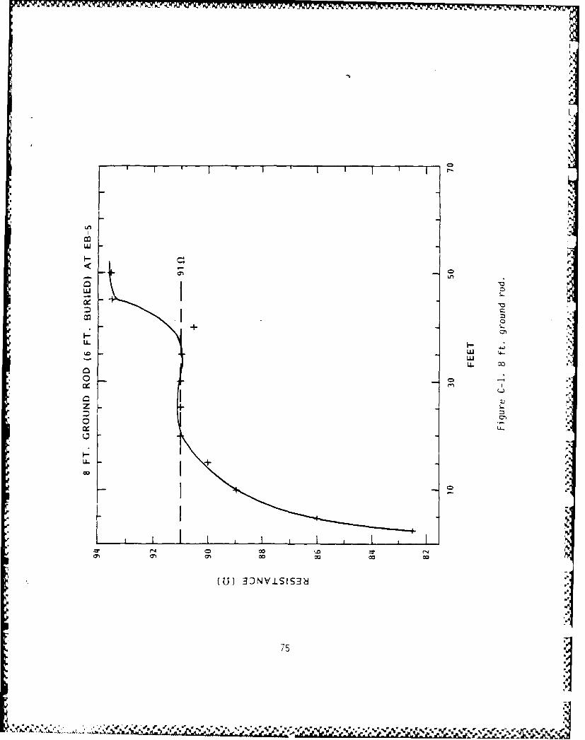
LU
a:
LL.
LL.
0) 00co
(U 0 0 -I3
* Z75

where
R = resistancep = earth resistivity, in 2-cm2 = rod length, in cmd = rod diameter, in cm
The measured resistance, using the "Megger" ground tester, of the 1.9 cm
(3/4 in) diameter copper plated steel rod driven 188 cm (74 in) into the
ground was 91 Q. Hence, the earth resistivity
RZ
P 0. 366 log 3X or p = 18,905 R-cm (C-2)
For the 46-m (150 ft) earth ground well at EB-5, the measured resistance
was 2.6 a (see Fig. C-2). For the 46-m (150 ft) earth ground well at WB-2,
the measured resistance was 3.5 s (see Fig. C-3).
Using the greater resistance of these two, then the resistivity using the
vertical rod (Eq. C-2) formula is
p = 11,334 Q-cm (C-3)
From these values we see that useful values for resistivity are 19 x
103 Q-cm for near surface installations and 11 x 103 Q-cm for deep buried
earth grounds at the PHETS facility.
Figures C-4 and C-5 show the measured resistance data for the East Bunker-5
and West Bunker-2, each disconnected from the 46-m (150 ft) earth ground
well.
If it is assumed that a buried circular plate is a good approximation for
the bermed cylinder then the emperical formula
R = 0.125 re + (C-4)re 2.5h+re)
is applicable where
R = resistance, in Qp = earth resistivity, in -cmh = depth of burial, in cmre = effective radius, in cm
76

L.4
z'
ILL ccII
-LJ
z0co-
co -7
I I
I-71

I XT XI I IR
z00
LI
Ln0
Ln~
wr
0 wb
oo~ wD
wk
I-r

- T7
z '~W~
zn LfL
D LL
C7
I- I-(A
LUU
uS
79 1Sv

C)i
z -
LU
ZC
800

reV / (C-5)
where
rDL (C-6)
-- 7 t2
where D = bermed cylinder diameter
L = bermed cylinder length
then
R =7.5 S
when h = 213 cm (7 ft)
p = 19 x 103 a-cm
Now, from the points at which the measured values for EB-5 and WB-2 have a
very steep slope (worst case)
R =5a
then
p 12,163 a-cm
In summary, the resistances are as follows:
" for the 46 m (150 ft) earth ground wells at any PHETS location
the resistance to earth is approximately 3.5 a and the earthresistivity is approximately 11 x 103 a-cm
* for a copper plated steel rod driven approximately 183 cm (6 ft)
into the ground the resistance to earth is approximately 91 Q
and the earth resistivity is approximately 19"x 10a S-cm
p .8

for the bermed instrumentation bunker treated as a buried flat
plate the resistance to earth is approximately 5 a and the earth
resistivity is approximately 12 x 103 a-cm
The primary conclusion here is that the stand alone bermed instrumentation
bunker provides a resistance to earth less than the 10 a required by
MIL-STD-188-124A and hence, the 46-m (150 ft) earth ground wells are not
needed.
8
82 '
•pV.~'- , 9 . % ~'~ R? - .N .-..