MV5 - Jag Valvejagvalve.com/wp-content/uploads/2012/06/5_MV5_Fully-Welded_Ball... · MV5-I....
18
Copyright © 2008 MIR VALVE. All Rights Reserved. MV5 C C opy opy rig rig ht ht © 2 © 2 008 008 MI MI R V R V ALV ALV E. E. All All Ri Ri ght ght s R s R ese ese rve rve d. d. Copyright © 2008 MIR VALVE All Rights Reserved Copyright © 2008 MIR VALVE. All Rights Reserved. Malaysia’s 1st API 6D Ball & Gate Valves & Actuators Manufacturer License No. 6D-0840 Cert. No. 224939
Transcript of MV5 - Jag Valvejagvalve.com/wp-content/uploads/2012/06/5_MV5_Fully-Welded_Ball... · MV5-I....

Copyright © 2008 MIR VALVE. All Rights Reserved.
MV5
C C Copyopyopyrigrigright ht ht © 2© 2© 2008008008 MI MI MIR VR VR VALVALVALVE. E. E. AllAllAll Ri Ri Rightghtghts Rs Rs Reseeseeserververved.d.d.Copyright © 2008 MIR VALVE All Rights ReservedCopyright © 2008 MIR VALVE. All Rights Reserved. Ma
la
ys
ia’s
1
st
A
PI
6D
B
al
l
&
Ga
te
V
al
ve
s
&
Ac
tu
at
or
s
Ma
nu
fa
ct
ur
er
License No. 6D-0840
Cert. No. 224939
elena.palla
Text Box
This brochure is currently being updated. Please contact MIR VALVE for clarification.

MIR VALVE Sdn. Bhd. (MIR VALVE) was incorporated on 27 December, 2006, obtained its Manufacturing License on 5 July 2007 and commenced business operations on 1 August 2007.
MIR VALVE is the 1st Malaysian company to design, manufacture and supply a complete range of API 6D Ball & Gate Valves and actuators for the oil, gas, petrochemical and power industries.
Our proud achievement of making the mission possible was through much hard work and dedication of the experienced and qualified personnel and concerted assistance from AST S.p.A, our established Italian technology partner cum shareholder (20% shareholding), via a 20-year Technology Agreement.
Our modern plant is located at Lot 3-4, Jalan Tanjung Keramat 26/35, Section 26, Shah Alam, Selangor, Malaysia, which is only 30 minutes drive from Kuala Lumpur city centre. Both the KLIA International Airport and Port of Klang are 45 minutes drive from the plant.
Our manufacturing and quality management systems have obtained ISO 9001:2000 certification (Certificate No: 224939) from Bureau Veritas. The American Petroleum Institute (API) has awarded us an API License (License No: 6D-0840) for our manufactured ball and gate valves to carry the API monogram.
Copyright © 2008 MIR VALVE. All Rights Reserved. 1
OUR PROMISE
Our principal business charter is customer satisfaction. Our commitment is to provide our valued customers with products and services of the highest quality, on-time delivery and competitive price. We are fully committed to provide the same high level of attention for any phase of the product life; from quotation to field service.
INTRODUCTIONINTRODUCTION
sugasini.thargiah
Typewriter
MV5

PRODUCT RANGE
ClassSize
150 300 400 600 900 1500
2”3”4”6”8”
10”12”14”16”18”20”22”24”26”28”30”32”34”36”40”42”46”48”56”60”
MV5-I
MV5-E
APPLICATION
MIR fully-welded ball valves are designed and manufactured in accordance with the API 6D Standards. The fully-welded body design reduces the number of potential leak paths that can be found in the bolted design.
The welded body configuration also allows for a considerable reduction in weight, especially if the welded ends version is selected.
Our fully-welded ball valves are well suited for oil and gas transmission and distribution systems, both onshore and offshore.
Copyright © 2008 MIR VALVE. All Rights Reserved. 2
GENERAL INFORMATIONGENERAL INFORMATION
sugasini.thargiah
Typewriter
MV5

Pressure
Leakage Check
Ball in Closed Position
Pressure
Pressure
Leakage Check
Ball in Closed Position
BODY CONSTRUCTION
The body is made of welded forged hot formed rings. Non Destructive Tests are performed as per ASME VIII Div. 1, App. 12 on the circumferential weld joints of the body. A dye penetrant test is performed on the welded joints.
SEAT SEAL
The floating seats are free to move slightly along the longitudinal axis of the valve. The valve is bidirectional. The initial seal, at extremely low pressure differential or vacuum conditions, is obtained through the force of the springs acting on the floating seats.
Line pressure, behind the seat ring, supplements the seat spring load to force the seat tightly against the ball.The soft sealing between the seat and the ball is achieved by a plastic insert. The seats are of a self-relieving design.
BLOCK AND BLEED
With the ball in a closed position and the pressure applied to one side of the ball, the liquid/gas can be relieved through the drain valve (API 6D sect. 5).
BODY DRAIN
The body drain is located in the lowest part of the body cavity and it is achieved by means of a 1/4 NPT drain valve with safety plug.
DOUBLE BLOCK-AND-BLEED(fully closed position)
With the ball in a closed position and the pressure simultaneously applied to both sides of the ball, the liquid/gas can be relieved through the drain valve (API 6D sect. 5).
Copyright © 2008 MIR VALVE. All Rights Reserved. 3
MV5-I
STANDARD DESIGNSTANDARD DESIGN
sugasini.thargiah
Typewriter
MV5
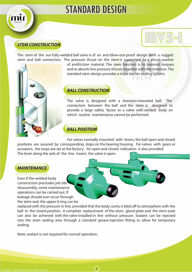
STEM CONSTRUCTION
The stem of the our fully-welded ball valve is of an anti-blow-out-proof design with a rugged stem and ball connection. The pressure thrust on the stem is supported by a thrust washer
BALL CONSTRUCTION
The valve is designed with a trunnion-mounted ball. The connection between the ball and the stem is designed to provide a large safety factor to a valve with welded body on which routine maintenance cannot be performed.
BALL POSITION
For valves normally mounted with levers, the ball open and closed positions are assured by corresponding stops on the bearing housing. For valves with gears or actuators, the stops are set at the factory. An open and closed indication is also provided. The lever along the axle of the line means the valve is open.
MAINTENANCE
Even if the welded body construction precludes job site disassembly, some maintenance operations can be carried out. If leakage should ever occur through the stem seal, the upper 0-ring can be replaced with the pressure in line, provided that the body cavity is bled off to atmosphere with the ball in the closed position. A complete replacement of the stem, gland plate and the stem seals can also be achieved with the valve installed in line without pressure. Sealant can be injected into the stem sealing area through a standard grease injection fitting to allow for temporary sealing.
Note: sealant is not required for normal operation.
Copyright © 2008 MIR VALVE. All Rights Reserved. 4
of antifriction material. The stem function is to transmit torques and to absorb line pressure thrusts together with the trunnion. The standard stem design provides a triple barrier sealing system.
MV5-I
STANDARD DESIGNSTANDARD DESIGN
sugasini.thargiah
Typewriter
MV5

Trunnion Design
1c. Body 2c. Closure 4. Ball 5. Stem 7b. Wrench 6a. Inner Seat Ring 9. Gland Plate 10. Gland Bushing 39a. Drain
118. Seat Ring 119. Seat Insert 123. Stem Key 127. Lower Trunnion Plate 131. Gland Plate Capscrew 132. Adapter Plate Capscrew 134. Stem O-Ring 135. Seat Gasket O-Ring 136. Gland Plate O-Ring
142. Seat Spring 150. Upper Thrust Washer 165. Bearing Housing 168. Stem Bearing 169. Lower Trunnion 189. Stem Grease Fi�ng 266. Stop Pin
The valve is designed for use with various material combina�ons depending on customer’sservice condi�on.
1c1c
189
142
135
118
119
4
20
169
1272c
39a
136
168
5
9
131
123
266
150
165
134
132
10
74
73
7b
Copyright © 2008 MIR VALVE. All Rights Reserved. 5
MV5-IAVAILABLE SIZE < NPS 6
VALVE ASSEMBLY & CROSS SECTIONVALVE ASSEMBLY & CROSS SECTION
sugasini.thargiah
Typewriter
MV5

12 2
1
BODY CONSTRUCTION
SEAT SEAL
The floating seats are free to move slightly along the longitudinal axis of the valve. The valve is bidirectional. The initial seal, at extremely low pressure differential or vacuum conditions, is obtained through the force of the springs acting on the floating seats. Line pressure, behind the seat ring, supplements the seat spring load to force the seat tightly against the ball. The sealing is performed by both a primary metal-to-metal seal and a secondary protected 0-ring seal. The soft sealing between the seat and the ball is achieved by an elastomeric 0-ring or a plastic 0-ring or insert, depending on the service conditions.
A grease injection system is provided for emergency seat sealing. In addition to the seat grease fittings, a check valve installed into the body prevents the escape of internal fluid.
DOUBLE-PISTON EFFECT SEAT DESIGN (DPE)
The seat design allows for both seats to seal with pressure acting from the same side of the valve. In the event of one seat becoming damaged, the user has the added advantage of the opposite seat sealing. There is a double barrier in both directions. Sealing is assured regardless of the direction of flow through the valve; if the upstream seat (1) becomes damaged and leaks, pressure entering the body cavity acts on the downstream seat (2) sealing the downstream seat tightly against the ball.Note: The D.P.E. feature and the Double Block and Bleed (D.B.B.) feature are not to be confused with each other.
Copyright © 2008 MIR VALVE. All Rights Reserved. 8
The body is made of welded forged rolled rings, rolled plates or casting parts depending on material availability and customer’s specifications. A wide selection of procedures cover the request for the welding of the various materials and joints. The welding is performed by our qualified personnel according to ASME IX. Non Destructive Tests are performed as per ASME VIII Div.1, App. 12 on the circumferential weld joints of the body. A dye penetrant test is performed on the welded joints. The compact shape of the body allows for an easy absorption of the bending loads coming from the pipeline.
MV5-E
STANDARD DESIGNSTANDARD DESIGN
sugasini.thargiah
Typewriter
MV5

DOUBLE BLOCK-AND-BLEED(fully closed position)
With the ball in a closed position and the pressure applied to both sides of the ball the liquid/gas can be relieved through the drain valve (API 6D sect. 5).
STEM CONSTRUCTION
BALL CONSTRUCTION
ACTUATOR
All MIR valves are manufactured with an adapter plate to enable the fitting of electric, hydraulic or pneumatic actuators. The mounting of actuators on new valves is performed within the MIR plant, assuring the integrity of the completed assembly. Modification of a manual valve to accept an actuator can be performed under the supervision of qualified MIR VALVE technicians.
The stem of our MV5 valve is of anti-blow-out design with a rugged stem and ball connection. The pressure thrust on the stem is supported by a thrust washer in antifriction material. The stem function is to trans-mit torque only. The stem design incorporates a triple barrier sealing system which is provided as standard.
The valve is designed with a trunnion-mounted ball. The two hubs rotate in a pair of self- lubricating bearings. The side thrust, coming from the line pressure against the closed ball is totally absorbed by the body through the upper and lower bearing retainers. The stem is separated from the ball. The absence of the side load on the stem assures low operating torque and long trouble free service life. The slot and tongue connection between the ball and the stem is designed to guarantee low stresses in the ball hub, thus giving the advantage of a large safety factor to a valve with welded body on which maintenance cannot be performed.
Copyright © 2008 MIR VALVE. All Rights Reserved. 9
MV5-E
STANDARD DESIGNSTANDARD DESIGN
sugasini.thargiah
Typewriter
MV5

BALL POSITION
The ball open and closed positions are assured by corresponding stops on the adapter plate. The valve is normally mounted with the actuator stops or gear stops set at the factory as primary stops. An open and closed indication is also provided.
INTERNAL COATING AND PROCESSES
The internal trim parts (ball, seats, stem) are usually electroless nickel plated (E.N.P.). The process provides corrosion resistance and low wear to the parts during operation. MIR VALVE operates its own in-house electroless nickel plating (ENP) facility. ASTM B656 and ASTM B733 are the standards for process and plating control. Strict quality control procedures for critical process conditions and for the plated components maintain plating consistency. Depending on the type of fluid, a variety of corrosion resistant and hard overlays can be applied in the critical sealing areas. All welding, as well as, internal and external coating are supported by detailed procedures.
BODY DRAIN
The body drain is located at the lowest part of the body cavity and it is achieved by means of a 1/2” (for valves up to 36”) or 1” (for larger valves) NPT drain valve with safety plug.
MAINTENANCE
Even if the welded body construction precludes job site disassembly, some maintenance operations can be performed. If leakage should ever occur through the stem seal, the upper 0-ring can be replaced with pressure in the line, provided that the body cavity is bled off to atmosphere with the ball in closed position.
A complete replacement of the stem, gland plate and the stem seals can also be achieved with the valve installed in line without pressure.
Sealant injection fittings are a standard feature on our MV5 valves, in order to provide emergency seat sealing. Sealant can also be injected into the stem sealing area through a standard grease injection fitting to allow for temporary sealing. Flushing through the relief valve and drain valve connections is possible, provided that there is no pressure in the line.Note : Sealant is not required for a normal operation.
Copyright © 2008 MIR VALVE. All Rights Reserved. 10
MV5-E
STANDARD DESIGNSTANDARD DESIGN
sugasini.thargiah
Typewriter
MV5
ExtensionLength
Pressure
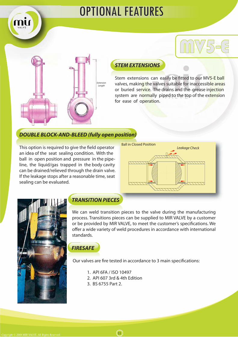
STEM EXTENSIONS
Stem extensions can easily be fitted to our MV5-E ball valves, making the valves suitable for inaccessible areas or buried service. The drains and the grease injection system are normally piped to the top of the extension for ease of operation.
DOUBLE BLOCK-AND-BLEED (fully open position)
This option is required to give the field operator an idea of the seat sealing condition. With the ball in open position and pressure in the pipe-line, the liquid/gas trapped in the body cavity can be drained/relieved through the drain valve. If the leakage stops after a reasonable time, seat sealing can be evaluated.
TRANSITION PIECES
.
FIRESAFE
Pressure
SS
Leakage CheckBall in Closed Position
Copyright © 2008 MIR VALVE. All Rights Reserved. 11
We can weld transition pieces to the valve during the manufacturing process. Transitions pieces can be supplied to MIR VALVE by a customer or be provided by MIR VALVE, to meet the customer’s specifications. We offer a wide variety of weld procedures in accordance with international standards.
MV5-E
Our valves are fire tested in accordance to 3 main specifications:
1. API 6FA / ISO 10497 2. API 607 3rd & 4th Edition 3. BS 6755 Part 2.
OPTIONAL FEATURESOPTIONAL FEATURES
sugasini.thargiah
Typewriter
MV5

2
142176
135143
6a137
1396b
37133
154
139
4151
152149
148
140
45178
175
174
149
5
124
123
150
134
10
132
160
131
266
9
189134
10
Bearing Retainer Design
er
1. Body2. Closure4. Ball5. Stem
6b. Outer Seat Ring6a. Inner Seat Ring
9. Gland Plate10. Gland Bushing37. Seat Stop Wash39. Drain Valve45. Seat Grease Fi�ng123.Stem Key124.Stem Key Capscrew
131. Gland Key Capscrew 132. Adapter Plate Capscrew 133. Puller Bushing Capscrew 134. Stem O-Ring 135. Seat Gasket O-Ring 136. Gland Plate O-Ring 137. Seal O-Ring 139. Seat Spring Pin 140. Bearing Retainer Pin 142. Cylindrical Spring 143. Seat Lock Ring 148. Bearing Retainer 149. Bearing
s
�ng
150.Upper Thrust Washer151.Lower Thrust Washer152.Spacer154.Relief Valve160.Adapter Plate174.Support Legs175.Li�ing Lug176.Grease U-Gasket178.Check Valve189.Stem Grease Fi266.Stop Pin
Copyright © 2008 MIR VALVE. All Rights Reserved. 12
The valve is designed for use with various material combina�ons depending on customer’s service condi�on.
MV5-EAVAILABLE SIZE > NPS 6
VALVE ASSEMBLY & CROSS SECTIONVALVE ASSEMBLY & CROSS SECTION
sugasini.thargiah
Typewriter
MV5

SUBSEA SERVICE
Our valves design takes into consideration of the restrictive criteria used in the definition of safety coefficients (pressure retaining components, E.S.D. valve stem connection) and in the corrosion protection of internal and external surfaces.
SOUR GAS SERVICE
A careful selection of the following materials is provided:
Carbon steel of low sulphur content, welding hardness within NACE limits, UT and LP Non Destructive Examination and relevant selection of seals materials.
MODULE READY FOR SUBSEA INSTALLATION
We can provide a valve package including the valve, actuator and transition pieces fully assembled, tested and inspected.
Copyright © 2008 MIR VALVE. All Rights Reserved. 19
SPECIAL APPLICATIONSSPECIAL APPLICATIONS
sugasini.thargiah
Typewriter
MV5
DESIGN SPECIFICATIONSDESIGN SPECIFICATIONS
Design :
API 6D / ISO 14313 ASME VIII-2, AD-132.1 MESC , PETRONAS, EPEMI
Body Thickness :
ANSI B16.34
Maximum Allowable Structure Torque (Mast) Sizing :
API 6D / ISO 14313 ASME VIII-2, AD-132.1 Guarantees the weakest point of drive train is external of valve’s body
Bolting :
ASME VIII-2, AD-132.1, ASME B16.34
Fire Safe :
ISO 10497 / API 6FA / BS 6755 PT.2
Top Works :
EN ISO 5211
Face To Face Dimension :
API 6D ANSI B16.10
End Connection :
Flange End - ASME B16.5 Weld End - ASME B16.25 Hub End - PROPRIETARY
Copyright © 2008 MIR VALVE. All Rights Reserved. 20
sugasini.thargiah
Typewriter
MV5

VALVE TESTING
PRESSURE TESTING TO API 6D
Leakage Rates Standard Performance Tests Visual & dimensional check High pressure hydrostatic shell test High pressure hydrostatic seats test Low pressure air seats test Stem torque check
ASMECLASS psi bar kg/cm² psi bar kg/cm² psi bar kg/cm² psi bar kg/cm²
150 275 19 19.3 413 28.5 29 303 20.9 21 100 6 7300 720 50 51 1080 75 77 792 55 56 100 6 7600 1440 99 101 2160 148.5 152 1584 108.9 111 100 6 7900 2160 149 152 3240 223.5 228 2376 163.9 167 100 6 71500 3600 248 253 5400 372 380 3960 272.8 278 100 6 72500 5988 413 421 8982 619.5 632 6587 454.3 463 100 6 7
RATING (1) BODY TEST H.P. SEAT TEST AIR SEAT TEST
(1) Please consult MIR VALVE personnel.
Conversion Factors 1 bar = 14.50 psi & 1 bar = 0,981 kg/cm² & 1 bar = 100 kpa 1kg/cm² = 14.22 psi 1 F = ( 1.8 x C ) + 32 & 1 C = ( F - 32 ) / 1.8
Type Part Sequence Duration (1) Description
A 1.5 x P.R (2) NPS 6 ~ NPS 10 5 Minutes
B 1.5 x P.R (2) NPS 12 ~ NPS 18 15 Minutes
C 1.5 x P.R (2) NPS 20 ~ NPS 60 30 Minutes
A Atmospheric
B Atmospheric
C 1.1 x P.R (2)
A 1.1 x P.R (2)
B Atmospheric
C Atmospheric
A Atmospheric
B Atmospheric
C 80 psig (5.5 bars)
A 80 psig (5.5 bars)
B Atmospheric
C Atmospheric
5 Minutes
5 Minutes
5 Minutes
5 Minutes
Shell hydrostatic test with valve half-open as follows ;*obtain hydrostatic test pressure* reduce pressure by 50% reset hydrostatic test pressure after stabilization and hold it for the duration.
Seat seal test at "C" end towards body "B"
Seat seal test at "A" end towards body "B"
Seat air seal teat at "C" end towards body "B"
Seat air seal teat at "A" end towards body "B"
Area Pressure (1)
HYDR
OSTA
TIC
SEAT
SHEL
L
AIR
(3)
(1) Minimum values (2) P.R. = Pressure Rating (3) Supplementary test to be carried out on request Blue = Liquid Yellow = Air
Standard
API 6D ISO 5208 Rate A ISO 5208 Rate D (1)
Soft-Seated Metal-Seated Cryogenic
Rating & Test Pressures At Ambient Temperature
ENGINEERING DATAENGINEERING DATA
Copyright © 2008 MIR VALVE. All Rights Reserved. 21
sugasini.thargiah
Typewriter
MV5

QUALITY STANDARDS
American Petroleum Institure - API API 6D API 6FA API 598 API 607 API 605
International Organization for Standardisation - ISO ISO 9001:2000 ISO 14313ISO 5211 ISO 10497
American Society of Mechanical Engineering - ASME ASME B 16.5 ASME B 16.10 ASME B 16.25ASME B 16.34 ASME B 31.3 ASME B 31.8ASME B 46.1
ENGINEERING DATAENGINEERING DATA
Copyright © 2008 MIR VALVE. All Rights Reserved. 22
sugasini.thargiah
Typewriter
MV5
CARBON STEEL
LOW ALLOY STEEL
BODY AND TRIM MATERIAL
BOLTS & NUTS
MATERIAL SPECIFICATIONSMATERIAL SPECIFICATIONS
Copyright © 2008 MIR VALVE. All Rights Reserved. 23
sugasini.thargiah
Typewriter
MV5

SEAT INSERT & SEALS MATERIAL OPERATING LIMITS
PLATING / COATING
NACE REQUIREMENT
MIN. MAX SEAT INSERT SEAT INSERT SEAL SEAL
NYLON®SMX -40 120 2500 N/A NPS 60 N/ANYLON 12-G ( LAURAMID) -60 100 2500 N/A NPS 60 N/ANYLON 6 ( DEVLON-V API) -60 140 2500 N/A NPS 60 N/APEEK -60 220 2500 N/A NPS 36 N/APTFE GLASS FILLED (25%) -100 200 600 N/A NPS 24 N/APTFE CARBON FILLE D (25%) -100 180 300 N/A NPS 24 N/APCTFE -196 150 2500 N/A NPS 36 N/AHNBR - Therban -40 150 600 2500 NPS 60 NPS 60FKM A ( VITON A) -29 180 600 2500 NPS 60 NPS 60FKM GLT (VITON GLT) -40 180 600 2500 NPS 60 NPS 60FKM AED ( VITON AED) -29 180 600 2500 NPS 60 NPS 60PTFE+ELGILOY SPRINGS -196 200 N/A 2500 N/A NPS 36FIRE SAFE GRAPHITE -240 520 N/A 2500 N/A NPS 60
SIZEMATERIAL
TEMPERATURE OC PRESSURE CLASS
MATERIAL SPECIFICATIONSMATERIAL SPECIFICATIONS
Copyright © 2008 MIR VALVE. All Rights Reserved. 24
sugasini.thargiah
Typewriter
MV5
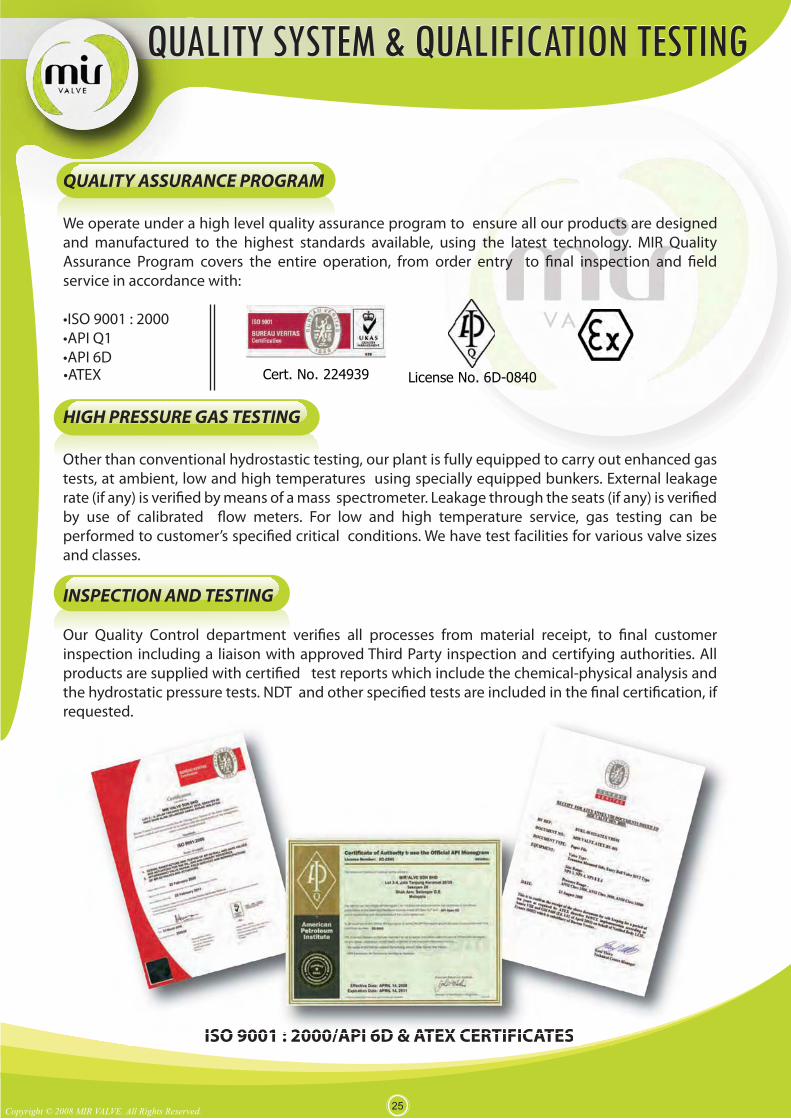
QUALITY ASSURANCE PROGRAM
We operate under a high level quality assurance program to ensure all our products are designed and manufactured to the highest standards available, using the latest technology. MIR Quality Assurance Program covers the entire operaservice in accordance with:
HIGH PRESSURE GAS TESTING
tests, at ambient, low and high temperatures using specially equipped bunkers. External leakage
and classes.
INSPECTION AND TESTING
inspection including a liaison with approved Third Party inspection and certifying authorities. All
requested.
Copyright © 2008 MIR VALVE. All Rights Reserved.25
ISO 9001 : 2000/API 6D & ATEX CERTIFICATES
QUALITY SYSTEM & QUALIFICATION TESTINGQUALITY SYSTEM & QUALIFICATION TESTING
inspection including a liaison with approved Third Party inspection and certifying authorities. Allproducts are supplied with certi ed test reports which include the chemical-physical analysis and
requested.
ISO 9001 : 2000/API 6D & ATEX CERTIFICATES
quested.
ISO 9001 : 2000/API 6D & ATEX CERTIFICATES
License No. 6D-0840Cert. No. 224939
sugasini.thargiah
Typewriter
MV5