Multicolor femtosecond pump-probe system with single ...
10
Review of Scientific Instruments ARTICLE scitation.org/journal/rsi Multicolor femtosecond pump-probe system with single-electron sensitivity at low temperatures and high magnetic fields Cite as: Rev. Sci. Instrum. 90, 123003 (2019); doi: 10.1063/1.5126157 Submitted: 30 August 2019 • Accepted: 30 November 2019 • Published Online: 19 December 2019 C. Traum, 1 P. Henzler, 1 S. Lohner, 1 H. Becker, 1 D. Nabben, 1 P. Gumbsheimer, 1 C. Hinz, 1 J. F. Lippmann, 1 S. Mahapatra, 2,a) K. Brunner, 2 D. V. Seletskiy, 1,3 and A. Leitenstorfer 1,b) AFFILIATIONS 1 Department of Physics and Center for Applied Photonics, University of Konstanz, D-78464 Konstanz, Germany 2 Institute of Physics, EP3, University of Würzburg, D-97074 Würzburg, Germany 3 Department of Engineering Physics, Polytechnique Montréal, Montréal, Québec H3T 1J4, Canada a) Current address: Department of Physics, Indian Institute of Technology Bombay, Mumbai, India. b) Email: [email protected] ABSTRACT We present an ultrafast spectroscopy system designed for temporal and spectral resolution of transient transmission changes after excitation of single electrons in solid-state quantum structures. The system is designed for optimum long-term stability, offering the option of hands-off operation over several days. Pump and probe pulses are generated in a versatile Er:fiber laser system where visible photon energies may be tuned independently from 1.90 eV to 2.51 eV in three parallel branches. Bandwidth-limited pulse durations between 100 fs and 10 ps are available. The solid-state quantum systems under investigation are mounted in a closed-cycle superconducting magnet cryostat providing temperatures down to 1.6 K and magnetic fields of up to 9 T. The free-standing cryomagnet is coupled to the laser system by means of a high- bandwidth active beam steering unit to eliminate residual low-frequency mechanical vibrations of the pulse tube coolers. High-NA objective lenses inside the sample chamber are employed for focusing femtosecond laser pulses onto the sample and recollection of the transmission signal. The transmitted probe light is dispersed in a grating monochromator equipped with a liquid nitrogen-cooled CCD camera, enabling a frame rate of 559 Hz. In order to eliminate spurious background effects due to low-frequency changes in the thermal equilibrium of the sample, we operate with a lock-in scheme where, instead of the pump amplitude, the pump-probe timing is modulated. This feature is provided without any mechanical action by an electro-optic timing unit inside the femtosecond Er:fiber system. The performance of the instrument is tested with spectrally resolved pump-probe measurements on a single negatively charged CdSe/ZnSe quantum dot under a magnetic field of 9 T. Selective initialization and readout of charge and spin states is carried out via two different femtosecond laser pulses. High-quality results on subpicosecond intraband relaxation dynamics after single-electron excitation motivate a broad variety of future experiments in ultrafast quantum optics and few-fermion quantum dynamics. Published under license by AIP Publishing. https://doi.org/10.1063/1.5126157 ., s I. INTRODUCTION Derivation of the modern postulates of quantum physics has been largely completed by the first part of the 20th century, marking the first quantum revolution in science. 1 Termed “second quantum revolution”, it is the contemporary motivation to engineer quan- tum systems in order to carry out certain practical tasks, the most sought-after being quantum computation and quantum information processing. The race for the quantum computer is still in its infancy, and the question of the best candidate system is far from being settled. Regardless of the details, however, all approaches require cryogenic temperatures to combat the detrimental effects of deco- herence. At this time, superconducting Josephson junctions rep- resent the platform coming closest to real-world applications but require operational temperatures below 100 mK 2 and therefore a sophisticated cooling apparatus. Among other top contenders, there Rev. Sci. Instrum. 90, 123003 (2019); doi: 10.1063/1.5126157 90, 123003-1 Published under license by AIP Publishing Konstanzer Online-Publikations-System (KOPS) URL: http://nbn-resolving.de/urn:nbn:de:bsz:352-2-fvc5xkrzg3sf1
Transcript of Multicolor femtosecond pump-probe system with single ...

Review ofScientific Instruments ARTICLE scitation.org/journal/rsi
Multicolor femtosecond pump-probe systemwith single-electron sensitivity at lowtemperatures and high magnetic fields
Cite as: Rev. Sci. Instrum. 90, 123003 (2019); doi: 10.1063/1.5126157Submitted: 30 August 2019 • Accepted: 30 November 2019 •Published Online: 19 December 2019
C. Traum,1 P. Henzler,1 S. Lohner,1 H. Becker,1 D. Nabben,1 P. Gumbsheimer,1 C. Hinz,1 J. F. Lippmann,1S. Mahapatra,2,a) K. Brunner,2 D. V. Seletskiy,1,3 and A. Leitenstorfer1,b)
AFFILIATIONS1Department of Physics and Center for Applied Photonics, University of Konstanz, D-78464 Konstanz, Germany2Institute of Physics, EP3, University of Würzburg, D-97074Würzburg, Germany3Department of Engineering Physics, Polytechnique Montréal, Montréal, Québec H3T 1J4, Canada
a)Current address: Department of Physics, Indian Institute of Technology Bombay, Mumbai, India.b)Email: [email protected]
ABSTRACTWe present an ultrafast spectroscopy system designed for temporal and spectral resolution of transient transmission changes after excitationof single electrons in solid-state quantum structures. The system is designed for optimum long-term stability, offering the option of hands-offoperation over several days. Pump and probe pulses are generated in a versatile Er:fiber laser system where visible photon energies may betuned independently from 1.90 eV to 2.51 eV in three parallel branches. Bandwidth-limited pulse durations between 100 fs and 10 ps areavailable. The solid-state quantum systems under investigation are mounted in a closed-cycle superconducting magnet cryostat providingtemperatures down to 1.6 K and magnetic fields of up to 9 T. The free-standing cryomagnet is coupled to the laser system by means of a high-bandwidth active beam steering unit to eliminate residual low-frequency mechanical vibrations of the pulse tube coolers. High-NA objectivelenses inside the sample chamber are employed for focusing femtosecond laser pulses onto the sample and recollection of the transmissionsignal. The transmitted probe light is dispersed in a grating monochromator equipped with a liquid nitrogen-cooled CCD camera, enablinga frame rate of 559 Hz. In order to eliminate spurious background effects due to low-frequency changes in the thermal equilibrium of thesample, we operate with a lock-in scheme where, instead of the pump amplitude, the pump-probe timing is modulated. This feature is providedwithout any mechanical action by an electro-optic timing unit inside the femtosecond Er:fiber system. The performance of the instrument istested with spectrally resolved pump-probe measurements on a single negatively charged CdSe/ZnSe quantum dot under a magnetic field of9 T. Selective initialization and readout of charge and spin states is carried out via two different femtosecond laser pulses. High-quality resultson subpicosecond intraband relaxation dynamics after single-electron excitation motivate a broad variety of future experiments in ultrafastquantum optics and few-fermion quantum dynamics.
Published under license by AIP Publishing. https://doi.org/10.1063/1.5126157., s
I. INTRODUCTION
Derivation of the modern postulates of quantum physics hasbeen largely completed by the first part of the 20th century, markingthe first quantum revolution in science.1 Termed “second quantumrevolution”, it is the contemporary motivation to engineer quan-tum systems in order to carry out certain practical tasks, the mostsought-after being quantum computation and quantum information
processing. The race for the quantum computer is still in its infancy,and the question of the best candidate system is far from beingsettled. Regardless of the details, however, all approaches requirecryogenic temperatures to combat the detrimental effects of deco-herence. At this time, superconducting Josephson junctions rep-resent the platform coming closest to real-world applications butrequire operational temperatures below 100 mK2 and therefore asophisticated cooling apparatus. Among other top contenders, there
Rev. Sci. Instrum. 90, 123003 (2019); doi: 10.1063/1.5126157 90, 123003-1
Published under license by AIP Publishing
Konstanzer Online-Publikations-System (KOPS) URL: http://nbn-resolving.de/urn:nbn:de:bsz:352-2-fvc5xkrzg3sf1

Review ofScientific Instruments ARTICLE scitation.org/journal/rsi
exist both atomic and solid-state approaches, with one of the lat-ter types being the Loss-DiVincenzo quantum computer, based onsingle-electron quantum dot (QD) gates.3 Quantum dot (QD)approaches require less aggressive cooling strategies; however, theysuffer from shorter decoherence times in comparison with, e.g.,atomic-based counterparts.1
In our studies, we ask the question whether certain quantumprocessing tasks may be carried out in solid-state systems on ultra-fast time scales, thus not being limited by dephasing on picosec-ond to nanosecond time scales? Quantum emitters, especially thosebased on II-VI semiconductor heterostructures, are characterized bystrong confinement potentials and large dipole moments that renderthem attractive platforms for studying light-matter interactions.4–6
Of special interest is the reduced screening found in these materialsystems. It leads to strong carrier exchange interactions that lift thedegeneracy of the electronic fine structure and allow for addressingsingle electronic states by femtosecond laser pulses. As a result, ultra-fast relaxation dynamics of distinct charge and spin configurationscan be studied by femtosecond pump-probe spectroscopy.7–9 More-over, we have already demonstrated quantum-dot based operationof a single-photon addition to a bright multimode coherent state.10
While we are currently developing strategies to extend such func-tionality efficiently toward few-photon coherent inputs,11 detailedinvestigations on single quantum systems are often challenged byweak signals potentially distorted by thermal artifacts.8,10
Here, we present an instrumental platform specifically designedfor high-precision three-color pump-probe spectroscopy on singlequantum emitters inside a low-temperature magnetic cryostat. Theschematic setup of the system is illustrated in Fig. 1, presentingthe main components from left to right, i.e., in the same order inwhich they are detailed in Secs II and III of this presentation. Sec-tion II describes the highly stable three-color Er:fiber laser systemdesigned for ultrafast selective initialization and readout of singlequantum-confined electronic states. It features the implementationof a specially developed pump-probe scheme for suppression of par-asitic artifacts in differential transmission signals. The closed-cyclesuperconducting magnetic cryostat and its spatial coupling to thelaser system by means of a broadband active beam stabilization arepresented in Sec. III. Along with describing the sample structurecontaining single negatively charged CdSe/ZnSe QDs, a comprehen-sive stability analysis of the magnetic cryostation and the demon-stration of shot-noise limited optical detection of differential trans-mission signals are the subject of this section. The overall perfor-mance of the experimental system is demonstrated in Sec. IV for thecase of two-color pump-probe spectroscopy on a single CdSe/ZnSequantum dot, where ultrafast buildup of inversion in the QD
FIG. 1. Schematic of the main components of the instrumentation system, specif-ically developed for ultrafast three-color pump-probe spectroscopy on singlequantum emitters situated inside a modern semiautomated magnetic cryostat.
amplifier is time resolved while in an external magnetic field ofB = 9 T. Finally, a conclusion and outlook are given in Sec. V.
II. LASER SYSTEM AND METHODOLOGYA detailed description of the Er:fiber laser and the nonlinear
frequency conversion stages is given in Sec. II A. The pump-probescheme developed for passive suppression of parasitic artifacts intransient transmission signals of single quantum systems is pre-sented in Sec. II B. This feature requires active modulation of thepump-pulse timing at switching times faster than the interpulse dis-tance of 25 ns. Its technical implementation is also subject of thissection.
A. Highly versatile three-color femtosecond Er:fibersystem
As sketched in Fig. 2, a soliton-mode-locked Er:fiber ring-oscillator12 represents the front end of our laser system. Built entirelyfrom polarization-maintaining single-mode fibers (PMSMFs) andpassively mode-locked by a semiconductor saturable absorber mir-ror, it generates a highly stable near-infrared train of femtosecondpulses at a repetition rate of frep = 40 MHz. The output spectrumis centered around a photon energy of Eph = 0.79 eV and features aspectral bandwidth of ∆E = 5.7 meV. An Er:fiber preamplifier scalesthe output power to Pavg = 10 mW and seeds three parallel Er:fiberamplifier branches that are precisely synchronized due to the highpassive stability of the all-fiber approach. A portion of the outputcontaining laser pulses with an energy of 25 pJ is used to directly seedthe probe branch. The remaining pulse energy seeds the two pump
FIG. 2. Schematic of the three-color femtosecond laser system with built-in pump-probe timing modulation. An Er:fiber oscillator followed by an Er:fiber preamplifieroutputs a near-infrared pulse train at a repetition rate of frep = 40 MHz at a cen-ter photon energy of Eph = 0.79 eV. This beam seeds three synchronized laserbranches (probe, pump I, and pump II). Each branch consists of a femtosec-ond Er:fiber amplifier with consecutive coherent supercontinuum generation in ahighly nonlinear fiber. Efficient conversion into the visible range is implementedby second harmonic generation in periodically poled LiNbO3 crystals. The fan-outdesign of the poling period enables flexible tuning of the photon energy. The outputspectra of visible laser pulses are modified in two 4f-shapers equipped with a spa-tial light modulator (probe) and a pair of razor blades (pump I) in their respectiveFourier planes. The timing modulation is implemented by means of a free-spacedelay line (short and long path) controlled via a fiber-coupled electro-optical router(EOR). URF denotes the driving voltage of the EOR. Neutral density filters (NDs,one adjustable) ensure identical seed power in both arms of the delay line.
Rev. Sci. Instrum. 90, 123003 (2019); doi: 10.1063/1.5126157 90, 123003-2
Published under license by AIP Publishing
Review ofScientific Instruments ARTICLE scitation.org/journal/rsi
branches, preceded by a timing modulation stage, which is describedin detail in Sec. II B. Each laser branch contains a nonlinear Er:fiberamplifier, providing output pulses with at least 45 kW peak power.This value enables efficient and particularly coherent frequency con-version13 in highly nonlinear germanosilicate bulk fibers. Featuringa reduced core radius for an enhanced nonlinearity and a carefullydesigned dispersion profile, these elements are capable of generatingbroadband near-infrared pulses with tailor-cut output spectra.14 Thehigh photon energy output of the dispersive branch of the supercon-tinuum can be optimized to cover the entire spectral range betweenEph = 0.86 eV and 1.40 eV. A spectral bandwidth of up to ∆E= 540 meV permits the generation of near-infrared few-cycle pulseswith pulse durations down to tP = 5.8 fs.15 Consecutive second-harmonic generation in periodically poled LiNbO3 crystals (PPLNs)converts the near-infrared laser light into the visible spectral range,while spectral compression due to sum frequency mixing guaranteesconversion efficiencies in excess of 30%.16 The fan-out design of thepoling period of the PPLNs allows for flexible tuning of the outputpulse photon energy within a spectral range between Eph = 1.90 eVand 2.51 eV. The three laser branches are equipped with differentPPLN lengths to allow for generation of bandwidth-limited pulseswith different durations, as required for various experiments. Theprobe branch generates light pulses with spectral widths between ∆E= 21 meV and 37 meV in order to read out a broad energy intervalin transient transmission spectroscopy. As shown in Sec. III D, thesinc-shaped spectral intensity leads to a photon energy-dependentshot-noise level. This effect is avoided by transforming into a flat-top spectrum by means of spectrally dependent attenuation in aspatial light modulator (SLM) situated in the Fourier plane of a 4fshaper. Controlled by a custom-designed self-learning algorithm, amodulated output spectrum is depicted in Fig. 8(c). The minimaltemporal duration of the probe pulses is tP = 100 fs. Output spec-tra generated in the pump I branch are as narrow as ∆E = (1.0± 0.2) meV. The spectral bandwidth can be further reduced by tworazor blades in the Fourier plane of a second 4f shaper, providinga minimal width of ∆E = 0.2 meV independent of central photonenergy. These pulses target the selective initialization of single con-fined electronic states and are perfectly suited for high-resolutionsingle-dot photoluminescence excitation (PLE) spectroscopy, as pre-sented in Fig. 9. Representing a compromise between selective opti-cal excitation of spectrally narrow electronic resonances in singlequantum systems and maintaining a femtosecond temporal resolu-tion in ultrafast pump-probe spectroscopy, branch pump II provideslaser pulses with bandwidths ranging from 3 meV to 6 meV. Thisinterval corresponds to pulse durations between tP = 400 fs and800 fs. The average output power of each of the three laser branchesis larger than Pavg > 3 mW (75 pJ), which easily allows us to drive typ-ical quantum emitters beyond the linear absorption regime. There-fore, we typically operate with substantial attenuation in ultrafastpump-probe spectroscopy on single QDs.
B. Suppression of parasitic artifacts by pump-probetiming modulation
In a typical pump-probe experiment, the spectrally resolved rel-ative differential transmission ∆T/T of the probe pulses is measured.∆T/T is defined as the normalized difference between the transmis-sion through the sample previously excited by a pump pulse and
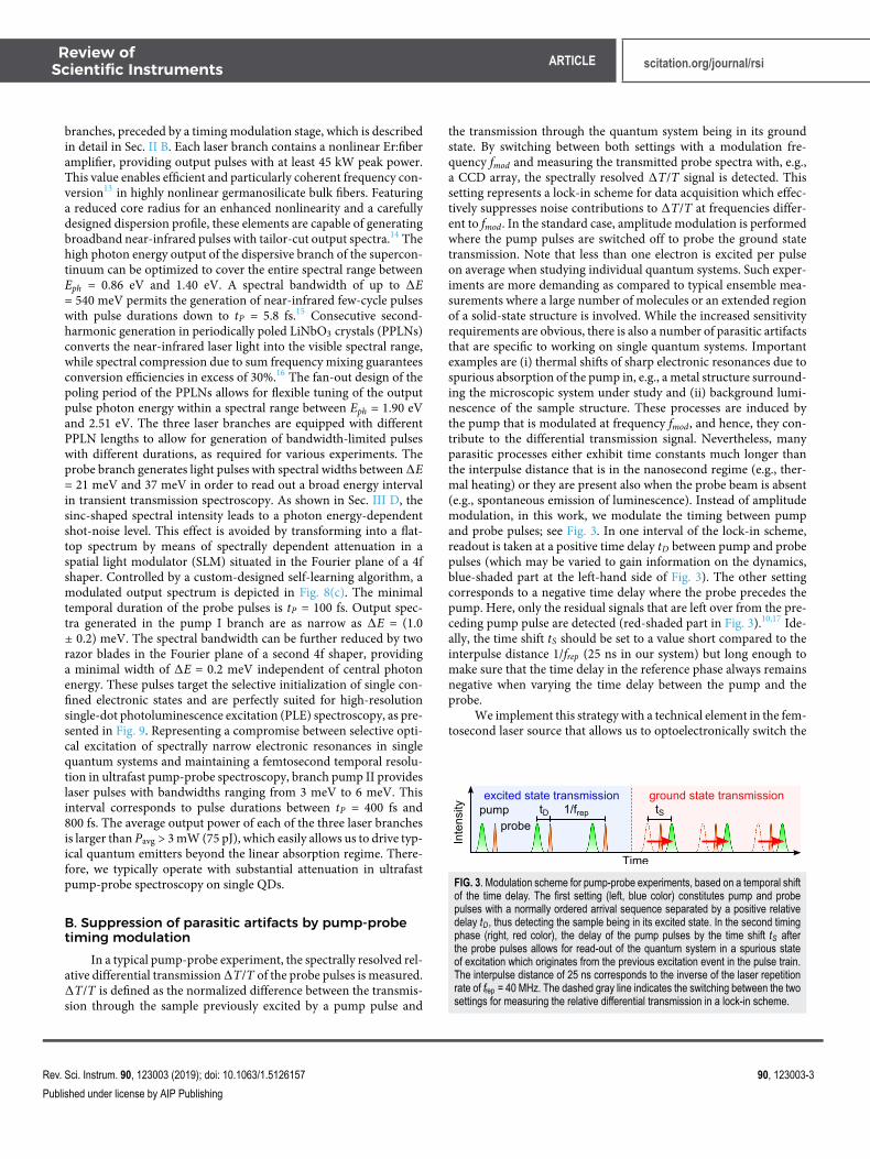
the transmission through the quantum system being in its groundstate. By switching between both settings with a modulation fre-quency fmod and measuring the transmitted probe spectra with, e.g.,a CCD array, the spectrally resolved ∆T/T signal is detected. Thissetting represents a lock-in scheme for data acquisition which effec-tively suppresses noise contributions to ∆T/T at frequencies differ-ent to fmod. In the standard case, amplitude modulation is performedwhere the pump pulses are switched off to probe the ground statetransmission. Note that less than one electron is excited per pulseon average when studying individual quantum systems. Such exper-iments are more demanding as compared to typical ensemble mea-surements where a large number of molecules or an extended regionof a solid-state structure is involved. While the increased sensitivityrequirements are obvious, there is also a number of parasitic artifactsthat are specific to working on single quantum systems. Importantexamples are (i) thermal shifts of sharp electronic resonances due tospurious absorption of the pump in, e.g., a metal structure surround-ing the microscopic system under study and (ii) background lumi-nescence of the sample structure. These processes are induced bythe pump that is modulated at frequency fmod, and hence, they con-tribute to the differential transmission signal. Nevertheless, manyparasitic processes either exhibit time constants much longer thanthe interpulse distance that is in the nanosecond regime (e.g., ther-mal heating) or they are present also when the probe beam is absent(e.g., spontaneous emission of luminescence). Instead of amplitudemodulation, in this work, we modulate the timing between pumpand probe pulses; see Fig. 3. In one interval of the lock-in scheme,readout is taken at a positive time delay tD between pump and probepulses (which may be varied to gain information on the dynamics,blue-shaded part at the left-hand side of Fig. 3). The other settingcorresponds to a negative time delay where the probe precedes thepump. Here, only the residual signals that are left over from the pre-ceding pump pulse are detected (red-shaded part in Fig. 3).10,17 Ide-ally, the time shift tS should be set to a value short compared to theinterpulse distance 1/frep (25 ns in our system) but long enough tomake sure that the time delay in the reference phase always remainsnegative when varying the time delay between the pump and theprobe.
We implement this strategy with a technical element in the fem-tosecond laser source that allows us to optoelectronically switch the
FIG. 3. Modulation scheme for pump-probe experiments, based on a temporal shiftof the time delay. The first setting (left, blue color) constitutes pump and probepulses with a normally ordered arrival sequence separated by a positive relativedelay tD, thus detecting the sample being in its excited state. In the second timingphase (right, red color), the delay of the pump pulses by the time shift tS afterthe probe pulses allows for read-out of the quantum system in a spurious stateof excitation which originates from the previous excitation event in the pulse train.The interpulse distance of 25 ns corresponds to the inverse of the laser repetitionrate of frep = 40 MHz. The dashed gray line indicates the switching between the twosettings for measuring the relative differential transmission in a lock-in scheme.
Rev. Sci. Instrum. 90, 123003 (2019); doi: 10.1063/1.5126157 90, 123003-3
Published under license by AIP Publishing
Review ofScientific Instruments ARTICLE scitation.org/journal/rsi
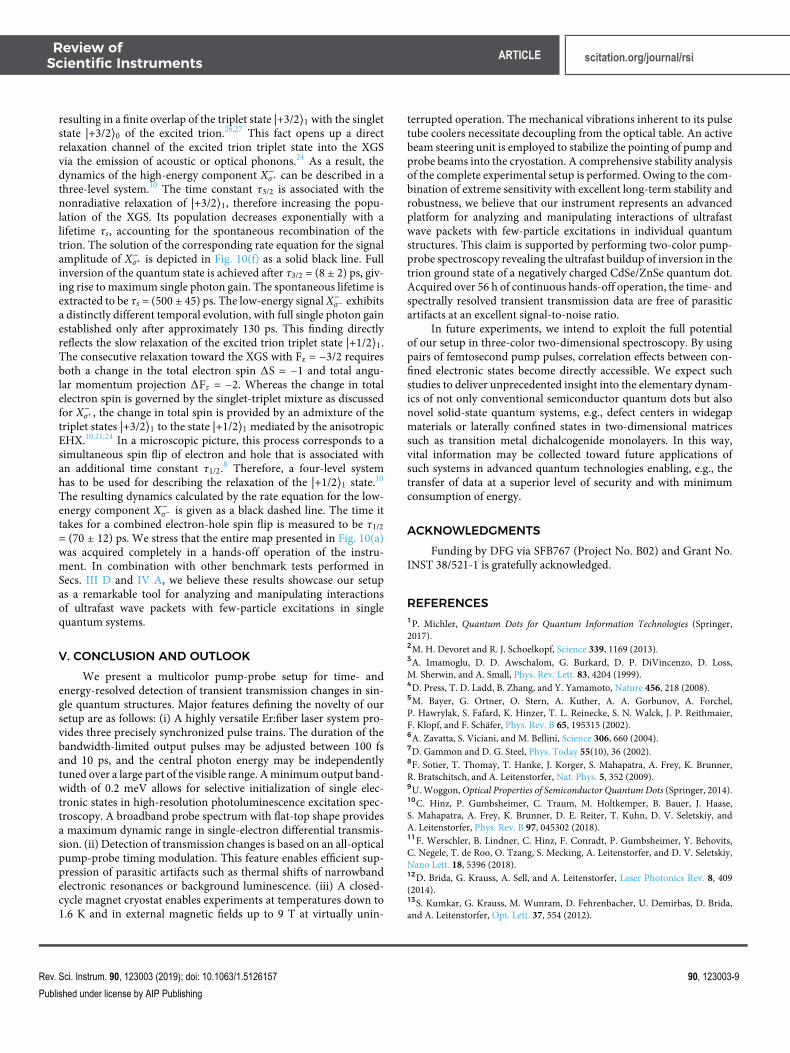
timing between pump and probe pulse trains by an interval of tS= 700 ps, i.e., without any mechanical movement and at a speedfaster than the interpulse distance. The scheme is depicted in theright upper corner of Fig. 2. After a beam splitter separating thepump and probe branches, a fiber-coupled electro-optic router(EOR) is located in the pump branch. Depending on the drivingvoltage URF , this element guides the incoming seed laser pulses forboth pumps I and II to one of its two fiber exits (see Fig. 2). A free-space collimator is spliced to each path, and each beam is coupledback into the fiber path after a different propagation length in freespace. The optical path difference between the short path (blue pathin Fig. 3, left panel in Fig. 4) and the long path (red, right panel) cor-responds to a pump-probe timing jump of tS = 700 ps. Free spacepropagation is exploited here in order to ensure identical dispersionin both passes. Finally, both optical paths are recombined by meansof a 50:50 fiber coupler, ensuring that the propagating laser pulsesare equally distributed to the two pump branches I and II of the lasersystem. Figure 4(a) shows an oscilloscope trace with 400 MHz band-width that is triggered by the probe branch and registers the pumppulse train. The temporal evolution of the switching voltage URF ofthe EOR is depicted in green. For URF = −2.8 V, the pump pulsestravel along the short path of the free-space delay line (blue). Whenswitching the driving voltage to URF = 2.8 V, the long path is selected(red) where the pump-probe timing is increased by tS = 700 ps.The EOR bandwidth of 3.4 GHz permits the pulse-by-pulse modu-lation of the pump arm and therefore operation up to the Nyquistlimit. To obtain clean measurements, the properties of the pumppulses have to be as independent as possible from the choice of thedelay line path they propagate through. Therefore, the fiber lengthsof both paths are adjusted to be exactly the same. Furthermore,two variable neutral density (ND) filters located in both free-spacepaths compensate for any difference in optical losses, balancing theintensity transmitted through the delay unit with a high degree ofprecision. Figure 4(b) compares the spectral densities of the visiblepump pulses in absolute units between the output of the short path(blue) and the long path (red). The maximum of the absolute spec-tral difference (green) amounts to 37 μW/THz, which correspondsto a relative spectral deviation of 1.4% between the spectra.
FIG. 4. (a) Visible pump pulse trains as detected with a Si photodiode by an oscil-loscope triggered to the probe pulses. Short (blue) and long path (red) pulse trainsare delayed with respect to each other by the action of the EOR. When the switch-ing voltage URF (green) is set from −2.8 V to 2.8 V, the pump pulses experiencean abrupt time shift of tS = 700 ps. (b) Spectra of pump pulses propagating alongshort and long paths of the delay line. The residual difference of both spectra isplotted in green.
Note that the repetition rate of our laser system could be eas-ily reduced by placing a fiber-coupled electro-optic modulator, e.g.,after the preamplifier.12 In this way, also quantum systems returningto their ground state on relatively long time scales beyond severalnanoseconds could be studied in detail.
III. LOW-TEMPERATURE MAGNETIC CRYOSTAT,SAMPLES, AND SIGNAL DETECTION
The second major component of our scientific instrument isthe closed-cycle superconducting magnetic cryostat. Section III Adescribes the coupling of pump and probe pulses to the cryomag-net and the spectrally resolved detection of transmitted probe pulses.Typical sample structures containing single CdSe/ZnSe quantumdots are presented in Sec. III B. A comprehensive stability analysis ofthe cryostation is carried out in Sec. III C, and the shot-noise-limitedanalysis of differential transmission is covered by Sec. III D.
A. Optical-to-cryomagnet interface and signaldetection
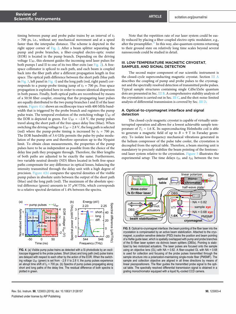
The closed-cycle magnetic cryostat is capable of virtually unin-terrupted operation and allows for a lowest achievable sample tem-perature of TL = 1.6 K. Its superconducting Helmholtz coil is ableto generate a magnetic field of up to B = 9 T in Faraday geom-etry. To isolate low-frequency mechanical vibrations generated inthe helium compressor of the pulse tube cooler, the cryostation isdecoupled from the optical table. Therefore, a beam steering unit ismandatory to precisely stabilize the beam pointing of the femtosec-ond laser system relative to the cryostation. Figure 5 illustrates theexperimental setup: The time delays tD1 and tD2 between the two
FIG. 5. Optical-to-cryomagnet interface: the beam pointing of the fiber laser into thecryostation is compensated by an active beam stabilization. Attached to the cryo-magnet, a position sensitive detector (PSD) tracks the position and beam pointingof a HeNe guide laser, which is spatially overlapped with pump and probe branchesof the Er:fiber laser system via dichroic beam splitters (DBSs). Pointing is stabi-lized by two motorized actuators. The laser pulses are focused onto the sampleusing an objective lens (OL) with NA = 0.82. A fiber-coupled OL with NA = 0.68is used for collection and focusing of the probe pulses transmitted through thesample structure into a polarization-maintaining single-mode fiber (PMSMF). Thesample and collection objective are aligned in all three directions by means oflinear piezopositioners. The fiber guides the transmitted probe signal to the opti-cal table. The spectrally resolved differential transmission signal is obtained in agrating monochromator equipped with a liquid N2-cooled CCD camera.
Rev. Sci. Instrum. 90, 123003 (2019); doi: 10.1063/1.5126157 90, 123003-4
Published under license by AIP Publishing

Review ofScientific Instruments ARTICLE scitation.org/journal/rsi
pump (light green and dark green) and probe pulse trains (orange)are implemented by means of computer-controlled linear mechan-ical delay stages, located in the optical path of the probe and onepump branch (not shown). A first dichroic beam splitter (DBS) spa-tially overlaps the femtosecond laser pulses with a HeNe guide laser(red). All four beams are then directed toward the cryostation by twopiezo-driven actuators attached to the optical table. Located in ambi-ent conditions on top of the cryomagnet, a second DBS separatesthe guide laser from pump and probe beams, sending the formerinto a position-sensitive detector (PSD). Tracking the beam point-ing of the guide laser with two quadrant photodiodes, it generatesan error signal processed by a proportional-integral-derivative con-troller of a bandwidth of 8 kHz. The signal is fed back to the motor-ized actuators that compensate for any drifts in the beam pointing ofpump and probe pulses in the cryostation by stabilizing the error sig-nals for the beam position and pointing direction detected with thePSD. The femtosecond laser pulses are reflected into the transmis-sion microscope situated in the variable temperature insert (VTI).A low-temperature objective lens (OL) with NA = 0.82 focuses thepump and probe beams onto the sample structure. Light transmittedthrough the sample structure is collected by a fiber-coupled low-temperature objective lens with NA = 0.68. Both sample and col-lection objective may be aligned in x, y, and z directions by meansof linear closed-loop piezopositioners with nanometer resolution.The transmitted laser pulses are guided back to the optical table by apolarization-maintaining single-mode fiber (PMSMF). After block-ing the pump by a dichroic filter with a >105 contrast, the probepulses are dispersed in an aberration-minimized grating spectrome-ter. 1340 spectral channels are detected by a liquid nitrogen-cooledCCD camera at a spectral resolution of 100 μeV, a quantum effi-ciency of 95%, and a 1760 Hz frame readout rate. The polarizationstate of the transmitted light is detected with a combination of linearpolarizer and half-wave plate, both located in front of the entranceslit of the spectrograph.
B. Single CdSe/ZnSe quantum dots embedded intonanophotonic structures
In order to demonstrate the performance of our system, weinvestigate CdSe/ZnSe QDs embedded into nanophotonic structuresto maximize the interaction with transmitted probe photons. Asillustrated in Fig. 6(a), single QDs are formed by self-assembledCdSe islands (red cones), which show diameters between 3 nm and6 nm with heights ranging from 2 nm to 4 nm.18 They are enclosed
FIG. 6. (a) Sketch of the nanophotonic sample structure: Single quantum dots areformed by self-assembled CdSe islands (red cones) in an epitaxial 100-nm-thickZnSe film (yellow). (b) For optical addressing and enhancement of light-matterinteraction, these structures are embedded into a circular aluminum (Al) nanoaper-ture (dark gray) with a diameter of approximately 250 nm processed on top of acrystalline silicon dioxide (SiO2) substrate.
into an epitaxially grown ZnSe matrix of 100 nm thickness. This epi-layer is removed from the original substrate by a lift-off process andoptically contacted to a 120 μm-thick crystalline quartz (SiO2) sub-strate. A Ga+-based focused ion beam is used to pattern the epilayerinto ZnSe discs (yellow), which subsequently are embedded into alu-minum (Al, dark gray) by means of a sequence of evaporation andetching steps.6 As sketched in Fig. 6(b), the resulting structure repre-sents a nanoaperture containing single QDs. Its diameter of 250 nmis adjusted to exploit the extraordinary transmission properties ofthese subwavelength structures. Together with reducing the effec-tive beam radius of the incident laser light, this feature enhancesthe light-matter interaction.19 Furthermore, the nanoapertures arefabricated with nearly perfect circular shape (not shown), render-ing them applicable for polarization-sensitive measurements. Eachstructure contains on average 10 QDs, whose electronic resonancesare spectrally separable due to the intrinsic size dispersion of the self-assembled CdSe islands. This fact allows for optical addressing ofsingle QDs.
C. Stability analysis of the magnetic cryostationThe mechanical stability of the cryostation is quantified by
detecting the probe transmission through an aluminum nanoaper-ture of a diameter of 250 nm. The sample temperature is set to TL= 1.6 K. The sampling frequency of the transmission signal is set to4 kHz. To characterize the influence of (i) the active beam stabiliza-tion and (ii) the helium compressor on the probe transmission, weswitch on or off one or both of the components. The upper graphof Fig. 7(a) (black) shows the transmission signal when both com-ponents are switched off. Its relative standard deviation amounts to
FIG. 7. (a) Analysis of the average probe power transmitted through a nanoaper-ture with a diameter of 250 nm sitting at a temperature of TL = 1.6 K inside thecryostation with a readout rate of 4 kHz. In the upper graph, the He compressorand beam stabilization are switched off (black). Upon activation of the beam sta-bilization, the noise amplitude reduces drastically (central graph, red). Switchingon the compressor induces acoustic noise, detected as a periodic modulation ofthe transmitted power (lower graph, blue). (b) Relative amplitude noise spectrumof the transmitted signal when the He compressor and beam stabilization are bothoperating. The modulation frequency fmod = 279.3 Hz selected for the experimentsis marked by a vertical red line. (c) Relative deviation of probe power over a timeperiod of 50 h (blue). The temporal evolution of the average input power is shownin green.
Rev. Sci. Instrum. 90, 123003 (2019); doi: 10.1063/1.5126157 90, 123003-5
Published under license by AIP Publishing

Review ofScientific Instruments ARTICLE scitation.org/journal/rsi
2.3%. Upon activation of the high-bandwidth active beam steering(center graph, red), the relative standard deviation of the transmis-sion reduces by nearly a factor of 8 to a value of 0.3%. Switching onthe He compressor induces low-frequency disturbances. Originatingfrom the pressure buildup in the pulse tubes installed next to the VTIof the cryomagnet, this motion cannot be compensated by the activebeam stabilization. The mechanical vibrations translate into a peri-odic modulation of the transmitted power [lower graph in Fig. 7(a),blue] where the relative amplitude of most fluctuations remains ator below 5% of the maximum signal. The operation frequency ofthe pulsed tube at 1.4 Hz and its higher harmonics are clearly dis-cernible in Fig. 7(b), where the relative intensity noise (RIN) of thetransmitted signal is shown when the compressor and beam stabi-lization are both switched on. Spectrally broad peaks between 20 Hzand 800 Hz are due to the mechanical resonance frequencies ofthe optical transmission microscope assembly, held at the bore ofthe cryomagnet by arms of a length of approximately 1 m. Despitethese features, the overall shape of the RIN signal exhibits a hyper-bolic frequency dependence, thus providing a clear motivation forhigh-frequency readout. In our implementation, the modulation fre-quency fmod is carefully set to 279.3 Hz (red vertical line) to avoidhigher harmonics of the operation frequency visible throughout theentire spectral range. Furthermore, this frequency represents theoptimal compromise between the noise amplitude of the transmittedsignal and the relative read-out noise of the CCD camera. To under-line the option for long-term hands-free operation of our system,the transmission signal is depicted over a time interval of 50 h as ablue graph in Fig. 7(c). The excellent stability of the average inputlaser power is shown in green. This analysis proves that uninter-rupted operation without any adjustment of our system is possibleover several days, thus enabling an unprecedented signal-to-noiseratio in nonlinear and ultrafast studies on single-electron quantumsystems.
D. Shot-noise-limited detection of spectrally resolveddifferential transmission
The noise properties of the probe pulse train transmittedthrough the nanoaperture are now analyzed with the spectrometerand the CCD camera. We record the intensity in two spectral chan-nels A (green) and B (violet) normalized by the respective meantransmission Tmean at a frame rate of fmeas = 558.6 Hz over a timeinterval of 142 s [left-hand side of Fig. 8(a)]. Both pixels are sepa-rated by an energy interval of 3.3 meV that is larger than the spec-tral width of the expected differential transmission features inducedby the quantum system [compare Fig. 8(b)]. The spectral positionsof channels A and B are marked in Fig. 8(c). The noise in bothchannels is dominated by the amplitude fluctuations induced bythe acoustic vibrations of the cryosystem. For comparison, the rel-ative intensity difference of both time traces A–B is plotted in bluein Fig. 8(a). A histogram of the likelihood for specific readout val-ues A–B is given in light blue at the right-hand side of Fig. 8(a). Itturns out that the width of a Gaussian normal distribution σΣ (solidblue line) fitted to these data is virtually identical to the distributionσS (dashed red) expected when assuming a Poissonian statistics ofthe difference of the photoelectron number detected in each readoutevent. Obviously, the signal A–B is limited by shot noise only. Thisfinding demonstrates a high degree of correlation of the technical
FIG. 8. (a) Left-hand side: Time traces of probe spectral intensities, acquired inCCD channels A (green) and B (violet) at a frame rate of fmeas = 558.6 Hz. Thechannels are separated in energy by 3.3 meV, and their spectral positions aremarked in the upper graph of (c). The relative difference of both channels A–B isplotted in blue. The corresponding signal histogram is depicted in light blue at theright-hand side. The width of a fitted Gaussian normal distribution (σ∑, solid blue)originates almost entirely from fundamental shot noise (σS, dashed red), under-lining the strong correlation of acoustic noise in intensity traces A and B. (b) Tworelative differential transmission spectra obtained under nominally identical inte-gration conditions are depicted as solid blue lines. 4 × 10⁴ individual probe pulsespectra were detected at a modulation frequency of fmod = 279.3 Hz, resulting in anintegration time of 142 s, respectively, and the time delay tD was set to 100 ps. At aphoton energy of 2.147 eV, a spectrally narrow feature can be assigned to the stim-ulated emission from the QD. By subtraction of a spline interpolation (red dashedline), the spectrally broad background originating from acoustic noise induced bythe cryostation is removed from the data (red solid line). (c) Root-mean-square ofspectrally resolved relative differential transmission (blue dots), entirely dictated byfundamental shot noise (red dashed line). The spectral intensity of probe pulses(orange with shading, upper graph) leads to an energy-dependent noise floor witha minimum value of 1.6 × 10⁻⁵. Transforming the probe pulse spectrum into a flat-top by means of pulse shaping with an SLM (see Sec. II A) results in an energyindependent noise floor within an energy interval of 34 meV (lower graph).
noise in the transmission signals A and B: the transverse mechanicalvibrations of the nanoaperture with respect to the confocal posi-tion of the probe are modulating the transmitted spectrum onlyin its total amplitude with negligible deviations between differentfrequency positions. Therefore, the vibration-induced distortions ofthe transmitted probe spectra may be clearly distinguished from thespectrally narrowband signals from the quantum system we want
Rev. Sci. Instrum. 90, 123003 (2019); doi: 10.1063/1.5126157 90, 123003-6
Published under license by AIP Publishing

Review ofScientific Instruments ARTICLE scitation.org/journal/rsi
to detect. Figure 8(b) shows two relative differential transmissionspectra as blue lines that were taken under nominally identical con-ditions. Each dataset is averaged over 4 × 10⁴ readouts of the CCDthat were acquired at a modulation frequency of fmod = 279.3 Hz.The time delay between pump and probe pulses is set to tD = 100 ps.At a probe photon energy of 2.147 eV, a narrowband spectral featureemerges. It originates from stimulated emission of single photonsby the quantum system.8 Due to the strong correlated noise con-tributed by acoustic vibrations, the signature is situated on top of apositive or negative background, which varies owing to the strongbut correlated contribution due to the technical vibrations. There-fore, we perform a least-square fit to the broadband backgroundbased on a spline interpolation of third order (dashed red line) andsubtract it from the data. The resulting background-corrected rel-ative differential transmission spectra are centered around zero inthe regions where no specific signal features occur. An example isshown as a solid red line in Fig. 8(b). Implemented in the experimentas real-time procession of acquired ∆T/T-spectra, this procedureestablishes a balanced detection of the narrowband changes in thequantum system in the differential transmission that is limited onlyby shot noise. The upper graph of Fig. 8(c) depicts the calculatedroot-mean-square value (rms) of the relative differential transmis-sion signal (blue dots), resolved for all pixels on the CCD sensor.The integration time of 142 s leads to a noise floor of 1.6 × 10⁻⁵
in the center of the spectrum where the photon flux per channelis maximum. The theoretical shot noise limit is indicated by thered dots, taking into account the spectral shape of the transmittedfJ-probe pulse (orange with shading). It turns out that our signalsare shot-noise-limited over the entire spectral range of the probeafter subtraction of the correlated acoustic noise. The pronouncedvariation of the spectral intensity of the transmitted probe pulsesleads to a strong dependence of the noise floor. In experiments onsingle-electron systems, however, only a fraction of the power avail-able from our femtosecond laser source may be used for probingin order to remain in a linear limit. This fact allows us to activelytransform the spectral intensity of the probe pulses into a flat-topdistribution via shaping the intensity amplitude in a 4f configura-tion containing an SLM (see Sec. II A). The resulting spectrum ispresented as an orange graph with shading in the lower graph ofFig. 8(c). As expected, the corresponding noise level remains con-stant within a wide interval of photon energy covering 34 meV.On the other side, the constant flux of probe power also allows usto operate at the optimum level of input intensity for all spectralchannels that is set by the saturation level of the CCD array per read-out event. In this way, we ensure that the maximum noise perfor-mance is reached over the entire spectral width covered by the probepulses.
IV. ULTRAFAST PUMP-PROBE SPECTROSCOPY ONSINGLE CdSe/ZnSe QUANTUM DOTS
The sensitivity of our experimental setup is demonstrated in atwo-color pump-probe experiment on a single CdSe/ZnSe QD in amagnetic field of 9 T. To this end, the precise knowledge of the elec-tronic structure of the QD outlined in Sec. IV A is a crucial prerequi-site. Consecutively, the femtosecond dynamics of two photo-excitedcharge and spin configurations are described in Sec. IV B.
A. Optical characterization of the electronic structure
Photoluminescence (PL) and photoluminescence excitation(PLE) spectra of a single negatively charged CdSe/ZnSe QD in amagnetic field of B = 9 T in Faraday geometry may be found in Fig. 9.The sample temperature is set to TL = 1.6 K. The QD is opticallyexcited by σ+ (i.e., right-handed) circularly polarized laser pulses atan average power of Pexc = 3 μW. The red solid line depicts the PLspectrum of the QD under a pump photon energy of Epu = 2.278 eV.Centered around an energy of 2.1817 eV, two Zeeman componentsof the fundamental trion emission X− are separated by 0.8 meV.As illustrated in the gray box, X− represents the radiative recom-bination of the trion ground state |±3/2⟩0 (XGS), consisting of twoelectrons and one hole in the lowest energy shells in the conduction(s) and valence (S) bands, respectively. The twofold energy degen-eracy is lifted by the external magnetic field. We denote a specificquantum state of the trion as |Fz⟩S = |S2, Sz⟩|jz⟩. F = S + j is theoverall angular momentum, consisting of the total electron spin S= s1 + s2 and the hole spin j. Sz and jz are projections along the z-axis, respectively, with z∥B. After recombination of the photoexcitedelectron-hole pair, the QD returns to its Zeeman-split ground stateconsisting of one single electron in its s-shell |±1/2⟩. Consequently,for the XGS where S = 0, the PL emission consists of a line doubletwith a low-energy component X−σ− and its high-energy counterpartX−σ+ that exhibit left- and right-handed circular polarization, respec-tively.20 Redshifted by an energy of 4.7 meV, a weaker doublet orig-inates from radiative recombination of charged biexciton groundstates into excited trion triplet states.21 These resonances are not dis-cussed in the present work. The PLE spectrum recorded by integrat-ing over the entire X− emission and varying the pump photon energy
FIG. 9. Stationary characterization of a single negatively charged CdSe/ZnSequantum dot (QD) in a magnetic field of B = 9 T and at a lattice temperature ofTL = 1.6 K. The red solid line shows the photoluminescence (PL) of a single QD,centered at EX− = 2.18 eV. The twofold degeneracy of the fundamental trion reso-nance X− is lifted by the magnetic field. A photoluminescence excitation spectrum(X−-PLE, green solid line) of energy resolution 0.2 meV reveals optical transitionsat higher energy (E − EX−). These measurements are performed using pumppulses generated in the pump I branch of the laser system with an average powerof Ppu = 3 μW. An example spectrum is represented by the black dashed graph.Spectral intensities of the probe and pump II pulses used for the ultrafast two-colorpump-probe experiments are shown in red and green dashed lines with shading,respectively. The inset graph qualitatively sketches excited and read-out opticaltransitions of the QD.
Rev. Sci. Instrum. 90, 123003 (2019); doi: 10.1063/1.5126157 90, 123003-7
Published under license by AIP Publishing

Review ofScientific Instruments ARTICLE scitation.org/journal/rsi
is depicted in solid green. The energy resolution of only 200 μeVis given by the spectrally narrowband excitation pulse generatedin the pump I branch (example spectrum given as a black dashedgraph). This measurement was obtained in a fully automated way bymotorized scanning of both the poling period of the fan-out PPLNcrystal used for second harmonic generation (SHG) (coarse adjust-ment of wavelength) and the angle of the diffraction grating in the4f-shaper (fine spectral selection, see Sec. II A). The PLE trace showsthree main absorption features. We concentrate on the line doubletcentered around an energy of 2.278 eV. These resonances are iden-tified as optical transitions of the QD from its ground state into thetriplet state of the excited trion, consisting of a charge configura-tion where two electrons are in the p-shell and s-shell, respectively,and one hole resides in the P-shell.10,22 σ+-polarized pump photonsare coupling to two of the four excited trion triplet states, namely,|+1/2⟩1 and |+3/2⟩1 (see the gray box). The corresponding opticaltransitions are separated by 1.0 meV due to a combined action ofelectron-hole exchange (EHX) and magnetic field.21,23
B. Femtosecond few-fermion dynamics in a strongmagnetic field
The central photon energy of the σ+-polarized pump pulses isnow tuned to 2.278 eV. Owing to the pulse duration of tpu = 600 fs,the spectral bandwidth covers both excited trion triplet states |+1/2⟩1and |+3/2⟩1 (see the dashed green line with shading in Fig. 9). Theaverage excitation power is set to Ppu = 3 μW. The photon energyof the linearly polarized probe is tuned to 2.180 eV, simultane-ously coupling to the low- and high-energy Zeeman components ofthe fundamental trion resonance (red dashed line with shading inFig. 9). The average probe power is set to Ppr = 1 μW at a pulse dura-tion of tpr = 100 fs. An external magnetic field of B = 9 T in Faradaygeometry is applied, and the sample is cooled down to a tempera-ture of TL = 1.6 K. Figure 10(a) depicts the color-coded spectrallyresolved differential transmission ∆T/T of a single QD for pump-probe time delays tD between −50 ps and 300 ps. ∆T/T spectra forrepresentative time delays are given in detail in Figs. 10(b)–10(e).For large negative delays tD ≪ 0 ps where the probe pulses precedethe pump pulses, no pump-induced changes are expected in the sig-nal. This is directly reflected in Fig. 10(b), underscoring the absenceof any long-lived parasitic (e.g., thermally induced) artifacts due tothe timing modulation explained in Sec. II B. For −5 ps < tD < 0 ps,a delay-dependent frequency modulation centered around the low-energy component of X− is caused by the perturbed dephasing of theprobe-induced polarization. The effect is successfully captured bythe numerical solution of dynamical Bloch equations for a two-levelsystem [orange solid line in Fig. 10(c)].8,10 For positive time delays,we observe a striking feature with two spectral components X−σ− andX−σ+ at energies of the Zeeman components of X−. The correspond-ing PL spectrum is depicted in Fig. 10(b) as a red dashed line. Thepositive differential transmission originates from two microscopiceffects: (i) Coulomb interactions between photoexcited carriers shiftelectronic resonances of the quantum system quasi-instantaneously,resulting in a steep increase in signal amplitude on a time scaleof less than 1 ps. (ii) Intraband scattering of hot carriers leads torelaxation toward the XGS. This state represents an inverted sys-tem providing optical gain limited to stimulated emission of a singlephoton that may be triggered by the probe pulse. As illustrated in
FIG. 10. (a) Spectrally resolved differential transmission ∆T/T of a single nega-tively charged CdSe/ZnSe QD as a function of time delay tD between pump andprobe pulses. The magnetic field strength is set to B = 9 T, and the sample temper-ature is TL = 1.6 K. The photon energy of the σ+ polarized pump pulses is tunedto excite trion triplet states in the QD with the average power of Ppu = 3 μW. Probepulses are linearly polarized with an average power of Ppr = 1 μW, and the photonenergy is centered on the fundamental trion resonance X−. (b) ∆T/T spectrum fortD =−50 ps. The red dashed graph shows the X− PL of the QD. (c) ∆T/T spectrumfor tD = −2 ps. The spectral modulation is due to a perturbed free induction decay.A model fit based on the numerical solution of two-level optical Bloch equationsis depicted in orange. (d) and (e) show ∆T/T spectra for tD = 30 ps and 130 ps,where single photon gain of low- and high-energy Zeeman-components X−σ− andX−σ+ is maximal, respectively. For positive time delays, fits for ∆T/T signals X−σ−and X−σ+ obtained from rate equations are given in (f) as black solid and dashedlines.
Fig. 9, the dynamics of the low-energy component X−σ− at a photonenergy of 2.1813 eV reflects the carrier relaxation from excited triontriplet state |+1/2⟩1, whereas the signal X−σ+ at an energy of 2.1821 eVmonitors the relaxation of the state |+3/2⟩1.10,22,24 By comparing theamplitudes of both signals in ∆T/T spectra for tD = 30 ps and 130 pspresented in Figs. 10(d) and 10(e), a markedly different relaxationdynamics of the triplet states toward the XGS is evident. First, therelaxation of the excited trion triplet state |+3/2⟩1 is discussed. Itsrelaxation toward the singlet-type XGS with a total angular momen-tum projection of Fz = +3/2 requires a change in total electron spinfrom 1 to 0, which might be a relatively slow process.24,25 In QDswith an elongated confinement potential, however, the anisotropicelectron-electron exchange (EEX) mixes triplet and singlet states,
Rev. Sci. Instrum. 90, 123003 (2019); doi: 10.1063/1.5126157 90, 123003-8
Published under license by AIP Publishing
Review ofScientific Instruments ARTICLE scitation.org/journal/rsi
resulting in a finite overlap of the triplet state |+3/2⟩1 with the singletstate |+3/2⟩0 of the excited trion.26,27 This fact opens up a directrelaxation channel of the excited trion triplet state into the XGSvia the emission of acoustic or optical phonons.24 As a result, thedynamics of the high-energy component X−σ+ can be described in athree-level system.10 The time constant τ3/2 is associated with thenonradiative relaxation of |+3/2⟩1, therefore increasing the popu-lation of the XGS. Its population decreases exponentially with alifetime τs, accounting for the spontaneous recombination of thetrion. The solution of the corresponding rate equation for the signalamplitude of X−σ+ is depicted in Fig. 10(f) as a solid black line. Fullinversion of the quantum state is achieved after τ3/2 = (8 ± 2) ps, giv-ing rise to maximum single photon gain. The spontaneous lifetime isextracted to be τs = (500 ± 45) ps. The low-energy signal X−σ− exhibitsa distinctly different temporal evolution, with full single photon gainestablished only after approximately 130 ps. This finding directlyreflects the slow relaxation of the excited trion triplet state |+1/2⟩1.The consecutive relaxation toward the XGS with Fz = −3/2 requiresboth a change in the total electron spin ∆S = −1 and total angu-lar momentum projection ∆Fz = −2. Whereas the change in totalelectron spin is governed by the singlet-triplet mixture as discussedfor X−σ+ , the change in total spin is provided by an admixture of thetriplet states |+3/2⟩1 to the state |+1/2⟩1 mediated by the anisotropicEHX.10,21,24 In a microscopic picture, this process corresponds to asimultaneous spin flip of electron and hole that is associated withan additional time constant τ1/2.8 Therefore, a four-level systemhas to be used for describing the relaxation of the |+1/2⟩1 state.10
The resulting dynamics calculated by the rate equation for the low-energy component X−σ− is given as a black dashed line. The time ittakes for a combined electron-hole spin flip is measured to be τ1/2= (70 ± 12) ps. We stress that the entire map presented in Fig. 10(a)was acquired completely in a hands-off operation of the instru-ment. In combination with other benchmark tests performed inSecs. III D and IV A, we believe these results showcase our setupas a remarkable tool for analyzing and manipulating interactionsof ultrafast wave packets with few-particle excitations in singlequantum systems.
V. CONCLUSION AND OUTLOOKWe present a multicolor pump-probe setup for time- and
energy-resolved detection of transient transmission changes in sin-gle quantum structures. Major features defining the novelty of oursetup are as follows: (i) A highly versatile Er:fiber laser system pro-vides three precisely synchronized pulse trains. The duration of thebandwidth-limited output pulses may be adjusted between 100 fsand 10 ps, and the central photon energy may be independentlytuned over a large part of the visible range. A minimum output band-width of 0.2 meV allows for selective initialization of single elec-tronic states in high-resolution photoluminescence excitation spec-troscopy. A broadband probe spectrum with flat-top shape providesa maximum dynamic range in single-electron differential transmis-sion. (ii) Detection of transmission changes is based on an all-opticalpump-probe timing modulation. This feature enables efficient sup-pression of parasitic artifacts such as thermal shifts of narrowbandelectronic resonances or background luminescence. (iii) A closed-cycle magnet cryostat enables experiments at temperatures down to1.6 K and in external magnetic fields up to 9 T at virtually unin-
terrupted operation. The mechanical vibrations inherent to its pulsetube coolers necessitate decoupling from the optical table. An activebeam steering unit is employed to stabilize the pointing of pump andprobe beams into the cryostation. A comprehensive stability analysisof the complete experimental setup is performed. Owing to the com-bination of extreme sensitivity with excellent long-term stability androbustness, we believe that our instrument represents an advancedplatform for analyzing and manipulating interactions of ultrafastwave packets with few-particle excitations in individual quantumstructures. This claim is supported by performing two-color pump-probe spectroscopy revealing the ultrafast buildup of inversion in thetrion ground state of a negatively charged CdSe/ZnSe quantum dot.Acquired over 56 h of continuous hands-off operation, the time- andspectrally resolved transient transmission data are free of parasiticartifacts at an excellent signal-to-noise ratio.
In future experiments, we intend to exploit the full potentialof our setup in three-color two-dimensional spectroscopy. By usingpairs of femtosecond pump pulses, correlation effects between con-fined electronic states become directly accessible. We expect suchstudies to deliver unprecedented insight into the elementary dynam-ics of not only conventional semiconductor quantum dots but alsonovel solid-state quantum systems, e.g., defect centers in widegapmaterials or laterally confined states in two-dimensional matricessuch as transition metal dichalcogenide monolayers. In this way,vital information may be collected toward future applications ofsuch systems in advanced quantum technologies enabling, e.g., thetransfer of data at a superior level of security and with minimumconsumption of energy.
ACKNOWLEDGMENTSFunding by DFG via SFB767 (Project No. B02) and Grant No.
INST 38/521-1 is gratefully acknowledged.
REFERENCES1P. Michler, Quantum Dots for Quantum Information Technologies (Springer,2017).2M. H. Devoret and R. J. Schoelkopf, Science 339, 1169 (2013).3A. Imamoglu, D. D. Awschalom, G. Burkard, D. P. DiVincenzo, D. Loss,M. Sherwin, and A. Small, Phys. Rev. Lett. 83, 4204 (1999).4D. Press, T. D. Ladd, B. Zhang, and Y. Yamamoto, Nature 456, 218 (2008).5M. Bayer, G. Ortner, O. Stern, A. Kuther, A. A. Gorbunov, A. Forchel,P. Hawrylak, S. Fafard, K. Hinzer, T. L. Reinecke, S. N. Walck, J. P. Reithmaier,F. Klopf, and F. Schäfer, Phys. Rev. B 65, 195315 (2002).6A. Zavatta, S. Viciani, and M. Bellini, Science 306, 660 (2004).7D. Gammon and D. G. Steel, Phys. Today 55(10), 36 (2002).8F. Sotier, T. Thomay, T. Hanke, J. Korger, S. Mahapatra, A. Frey, K. Brunner,R. Bratschitsch, and A. Leitenstorfer, Nat. Phys. 5, 352 (2009).9U. Woggon, Optical Properties of Semiconductor QuantumDots (Springer, 2014).10C. Hinz, P. Gumbsheimer, C. Traum, M. Holtkemper, B. Bauer, J. Haase,S. Mahapatra, A. Frey, K. Brunner, D. E. Reiter, T. Kuhn, D. V. Seletskiy, andA. Leitenstorfer, Phys. Rev. B 97, 045302 (2018).11F. Werschler, B. Lindner, C. Hinz, F. Conradt, P. Gumbsheimer, Y. Behovits,C. Negele, T. de Roo, O. Tzang, S. Mecking, A. Leitenstorfer, and D. V. Seletskiy,Nano Lett. 18, 5396 (2018).12D. Brida, G. Krauss, A. Sell, and A. Leitenstorfer, Laser Photonics Rev. 8, 409(2014).13S. Kumkar, G. Krauss, M. Wunram, D. Fehrenbacher, U. Demirbas, D. Brida,and A. Leitenstorfer, Opt. Lett. 37, 554 (2012).
Rev. Sci. Instrum. 90, 123003 (2019); doi: 10.1063/1.5126157 90, 123003-9
Published under license by AIP Publishing

Review ofScientific Instruments ARTICLE scitation.org/journal/rsi
14A. Sell, G. Krauss, R. Scheu, R. Huber, and A. Leitenstorfer, Opt. Express 17,1070 (2009).15S. Baumann, W. Paul, T. Choi, C. P. Lutz, A. Ardavan, and A. J. Heinrich,Science 350, 417 (2015).16K. Moutzouris, F. Adler, F. Sotier, D. Träutlein, and A. Leitenstorfer, Opt. Lett.31, 1148 (2006).17H. Shigekawa, O. Takeuchi, and M. Aoyama, Sci. Technol. Adv. Mater. 6, 582(2005).18S. Mahapatra, K. Brunner, and C. Bougerol, Appl. Phys. Lett. 91, 153110 (2007).19C. Genet and T. W. Ebbesen, Nature 445, 39 (2007).20I. A. Akimov, T. Flissikowski, A. Hundt, and F. Henneberger, Phys. Status Solidi201, 412 (2004).
21I. A. Akimov, K. V. Kavokin, A. Hundt, and F. Henneberger, Phys. Rev. B 71,075326 (2005).22J. Huneke, I. D’Amico, P. Machnikowski, T. Thomay, R. Bratschitsch, A. Leit-enstorfer, and T. Kuhn, Phys. Rev. B 84, 115320 (2011).23K. V. Kavokin, Phys. Status Solidi 195, 592 (2003).24M. E. Ware, E. A. Stinaff, D. Gammon, M. F. Doty, A. S. Bracker, D. Gershoni,V. L. Korenev, S. C. Badescu, Y. Lyanda-Geller, and T. L. Reinecke, Phys. Rev. Lett.95, 177403 (2005).25S. C. Badescu, Y. B. Lyanda-Geller, and T. L. Reinecke, Phys. Rev. B 72, 161304(2005).26K. V. Kavokin, Phys. Rev. B 69, 075302 (2004).27M. M. Glazov and V. D. Kulakovskii, Phys. Rev. B 79, 195305 (2009).
Rev. Sci. Instrum. 90, 123003 (2019); doi: 10.1063/1.5126157 90, 123003-10
Published under license by AIP Publishing