Multi-conductor Lighting Busbar System - E-Line_DL.pdf · Multi-conductor Lighting Busbar System...
21
ISO 9001 14001 Q U A L I T Y A N D E N V I R O N M E N T A L M A N A G E M E N T S Y S T E M S www.eae.com.tr Akcaburgaz Mahallesi, 119. Sokak, No:10 34510 Esenyurt-Istanbul-Turkey Tel: +90 (212) 866 20 00 Faks: +90 (212) 886 24 20 T E ME 04 IEC 60439-2 s Multi-conductor Lighting Busbar System 25-32-40 A ATA MATBAACILIK / A.C.E./ 612 40 66 Catalogue 07-Eng. / 02 1.000 pcs. 19/02/2011 EAE has full right to make any revisions or chances on this catalogue without any prior notice.
-
Upload
truongnguyet -
Category
Documents
-
view
219 -
download
0
Transcript of Multi-conductor Lighting Busbar System - E-Line_DL.pdf · Multi-conductor Lighting Busbar System...

ISO9001
14001
QUALI
TY
AN
DEN
VIR
ONMENTAL MANAGEM
EN
TS
YSTEM
S
www.eae.com.tr
Akcaburgaz Mahallesi,
119. Sokak, No:10 34510
Esenyurt-Istanbul-Turkey
Tel: +90 (212) 866 20 00
Faks: +90 (212) 886 24 20
T E
ME 04
IEC 60439-2 s
Multi-conductor Lighting Busbar System
25-32-40 A
ATA
MA
TB
AA
CIL
IK /
A.C
.E./
61
2 4
0 6
6C
ata
log
ue
07-E
ng
. /
02 1.0
00 p
cs. 1
9/0
2/2
011
EA
E h
as fu
ll ri
gh
t to
make a
ny r
evis
ion
s o
r ch
an
ces o
n t
his
cata
log
ue w
ith
ou
t an
y p
rio
r n
otice.

w w w . e a e . c o m . t r
2-3
4
5
6-7
8
9-10
11-12
3
4-15
6
17
18
19
20
1
1
1
Introduction
Order Code System
Technical Characteristics
Standard Components
Special Straight Length
Feeder Boxes
Tap-Off Plugs
Tap-Off Boxes
Support Systems
DL Joint Installation
DL Tap-Off Plug Installation
EC Certificate of Conformity
Product Overview
Project Design Form
CONTENTS
3000
330
330
750
750 750 750
750 750 420
420
2 3
E L E K T R İ K E L E K T R İ K
E DLLINEGeneral Characteristics
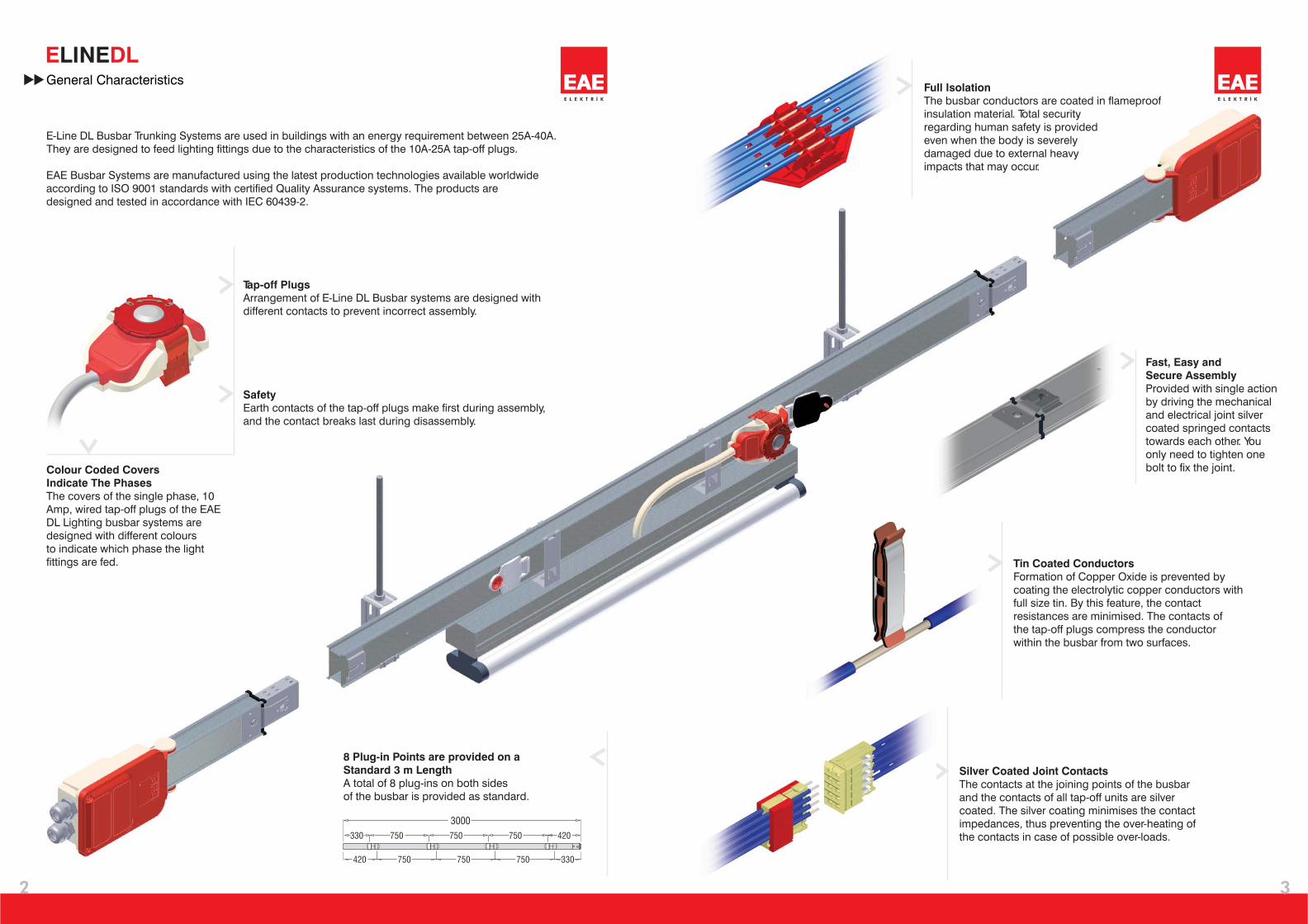
Silver Coated Joint Contacts
The contacts at the joining points of the busbar
and the contacts of all tap-off units are silver
coated. The silver coating minimises the contact
impedances, thus preventing the over-heating of
the contacts in case of possible over-loads.
Tin Coated Conductors
Formation of Copper Oxide is prevented by
coating the electrolytic copper conductors with
full size tin. By this feature, the contact
resistances are minimised. The contacts of
the tap-off plugs compress the conductor
within the busbar from two surfaces.
Fast, Easy and
Secure Assembly
Provided with single action
by driving the mechanical
and electrical joint silver
coated springed contacts
towards each other. You
only need to tighten one
bolt to fix the joint.
8 Plug-in Points are provided on a
Standard 3 m Length
A total of 8 plug-ins on both sides
of the busbar is provided as standard.
Full Isolation
The busbar conductors are coated in flameproof
insulation material. Total security
regarding human safety is provided
even when the body is severely
damaged due to external heavy
impacts that may occur.
Safety
Earth contacts of the tap-off plugs make first during assembly,
and the contact breaks last during disassembly.
Colour Coded Covers
Indicate The Phases
The covers of the single phase, 10
Amp, wired tap-off plugs of the EAE
DL Lighting busbar systems are
designed with different colours
to indicate which phase the light
fittings are fed.
Tap-off Plugs
Arrangement of E-Line DL Busbar systems are designed with
different contacts to prevent incorrect assembly.
E-Line DL Busbar Trunking Systems are used in buildings with an energy requirement between 25A-40A.
They are designed to feed lighting fittings due to the characteristics of the 10A-25A tap-off plugs.
EAE Busbar Systems are manufactured using the latest production technologies available worldwide
according to ISO 9001 standards with certified Quality Assurance systems. The products are
designed and tested in accordance with IEC 60439-2.

2 5 2 5 B --
25 A 2
32 A 3
40 A 4
25 A 2
32 A 3
40 A 4
Busbar
Current Rating 1
Busbar
Current Rating 2
DL T DSS
STD
X
B1
B2
B1
B2
4
E L E K T R İ K
E DLLINEBUSBAR TYPE
BUSBAR CURRENT RATING 1
BUSBAR CURRENT RATING 2
COMPONENT
CONDUCTOR CONFIGURATION
COMPONENT REFERENCES
Order Code System
Busbar Type
2 Conductors 2
3 Conductors 3
4 Conductors 4
5 Conductors 5
2 Conductors 2
3 Conductors 3
4 Conductors 4
5 Conductors 5
1st
Conductor Configuration
2nd
Conductor Configuration
UNPAINTED / PAINTED
UNPAINTED
PAINTED
-
B
Paint
Standard Length
Special Length
Feeder Box
End Feeder Box
Underfloor Feeder
Underfloor End Feeder

5
E L E K T R İ K
E DLLINE
V
Hz
kA
kA
m / m
m / m
m / m
W / m
mm²
mm²
mm²
kg/m
kg/m
50/60
kA
rms
R
X
Z
I²R
20
1
DL 2424 DL 3434 DL 4444
�
�
�
IEC 60439 1-2
f
IP 55
Icw
Ip
2.50
4.00
21
5.42
2.02
5.61
3.85
3.20
18.30
3.20
1.40
1.50
4.00
6.50
21
2.90
1.27
3.17
5.65
6.00
18.30
6.00
1.60
1.72
AIn 25 32 40
3.00
5.00
21
4.46
1.62
4.47
5.24
4.00
18.30
4.00
1.43
1.55
10001000Ui 1000
Voltage Drop Calculation
U=
U=
I.2L (R.cos
3.I.L (R.cos
V
V
).10
).10
-3
-3
+X.sin�
+X.sin�
The maximum permitted load for the support of light fittings of the system is 15 kg. concentrated or
20 kg. distributed for a recommended support span of every 2 meters without any deformation of
the housing.
For three phase ;
�
�
��
� �
�
����
����
��
��
�
�
U =
I =
L =
=
R =
X = Reactance
m
m
m
m
�
�
�
�
V
A
mt
1.00
0.50
0.25
�
�
Voltage drop of a busbar system can be calculated with the following formula taking into account the “ ”
load distribution constant.
For single phase;
�
Load Distribution Constant
Load concentrated at the
end of line. Line fed from
one end of the line.
Distributed load. Line fed
from one end of the line.
Distributed load. Line fed
from both ends of the line.
Voltage Drop
Rated Current
Length of Line
Load Distribution Constant
Resistance
Technical Characteristics
Rated Current
Standards
Rated Insulation Voltage
Rated Frequency
Protection Degree
Short-Circuit (1 sec)
Short-Circuit (Peak)
Short Circuit(Peak)Tested 1 msec.
Resistance
Reactance
Impedance
Joule Losses At In
L1, L2, L3, N (Cross Section)
PE (Housing)
PE (Conductor)
Weight (4 Conductors)
Weight (5 Conductors)

E L E K T R İ K
Standard Elements
CPE
6
E DLLINE
3000
330
330
750
750 750 750
750 750 420
420
CPE

7
E L E K T R İ K
E DLLINE
DL 2424 2x25 A Busbar
DL 3434 2x32 A Busbar
DL 4444 2x40 A Busbar
84165
84167
84169
4+4
4+4
4+4
25
32
40
84177
84179
84181
DL 2422 2x25 A Busbar
DL 3432 2x32 A Busbar
DL 4442 2x40 A Busbar
4+2
4+2
4+2
25
32
40
DL 2222 2x25 A Busbar
DL 3232 2x32 A Busbar
DL 4242 2x40 A Busbar
84189
84191
84193
25
32
40
2+2
2+2
2+2
DL 2525 2x25 A Busbar
DL 3535 2x32 A Busbar
DL 4545 2x40 A Busbar
5+5
5+5
5+5
84201
84203
84205
25
32
40
DL 2523 2x25 A Busbar
DL 3533 2x32 A Busbar
DL 4543 2x40 A Busbar
5+3
5+3
5+3
84213
84215
84217
25
32
40
DL 2323 2x25 A Busbar
DL 3333 2x32 A Busbar
DL 4343 2x40 A Busbar
84225
84227
84229
25
32
40
3+3
3+3
3+3
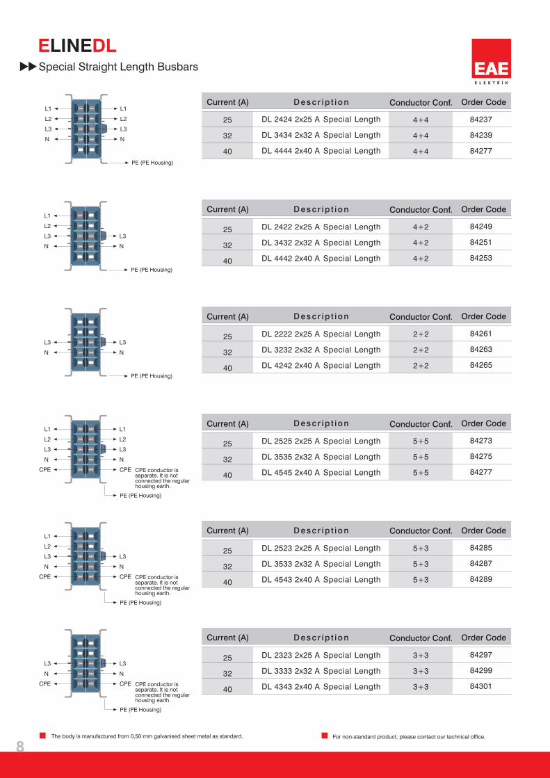
For non-standard product, please contact our technical office.
PE (PE Housing)
PE (PE Housing)
CPE conductor isseparate. It is notconnected the regularhousing earth.
CPE conductor isseparate. It is notconnected the regularhousing earth.
CPE conductor isseparate. It is notconnected the regularhousing earth.
PE (PE Housing)
PE (PE Housing)
PE (PE Housing)
Standard Elements
The body is manufactured from 0,50 mm galvanised sheet metal as standard.
PE (PE Housing)
Current (A) Conductor Conf.D es c r ip t io n Order Code
Current (A) Conductor Conf.D es c r ip t io n Order Code
Current (A) Conductor Conf.D es c r ip t io n Order Code
Current (A) Conductor Conf.D es c r ip t io n Order Code
Current (A) Conductor Conf.D es c r ip t io n Order Code
Current (A) Conductor Conf.D es c r ip t io n Order Code
E L E K T R İ K
84249
84251
84253
4+2
4+2
4+2
25
32
40
5+5
5+5
5+5
84273
84275
84277
25
32
40
5+3
5+3
5+3
84285
84287
84289
25
32
40
84297
84299
84301
25
32
40
3+3
3+3
3+3
84261
84263
84265
25
32
40
2+2
2+2
2+2
8
E DLLINE
84237
84239
84277
4+4
4+4
4+4
25
32
40
PE (PE Housing)
PE (PE Housing)
PE (PE Housing)
DL 2525 2x25 A
DL 3535 2x32 A
DL 4545 2x40 A
Special Length
Special Length
Special Length
DL 2523 2x25 A
DL 3533 2x32 A
DL 4543 2x40 A
Special Length
Special Length
Special Length
DL 2323 2x25 A
DL 3333 2x32 A
DL 4343 2x40 A
Special Length
Special Length
Special Length
DL 2222 2x25 A
DL 3232 2x32 A
DL 4242 2x40 A
Special Length
Special Length
Special Length
Special Straight Length Busbars
DL 2424 2x25 A
DL 3434 2x32 A
DL 4444 2x40 A
Special Length
Special Length
Special Length
CPE conductor isseparate. It is notconnected the regularhousing earth.
CPE conductor isseparate. It is notconnected the regularhousing earth.
CPE conductor isseparate. It is notconnected the regularhousing earth.
PE (PE Housing)
PE (PE Housing)
PE (PE Housing)
Current (A) Conductor Conf.D es c r ip t io n Order Code
Current (A) Conductor Conf.D es c r ip t io n Order Code
Current (A) Conductor Conf.D es c r ip t io n Order Code
Current (A) Conductor Conf.D es c r ip t io n Order Code
Current (A) Conductor Conf.D es c r ip t io n Order Code
Current (A) Conductor Conf.D es c r ip t io n Order Code
For non-standard product, please contact our technical office.The body is manufactured from 0,50 mm galvanised sheet metal as standard.
DL 2422 2x25 A
DL 3432 2x32 A
DL 4442 2x40 A
Special Length
Special Length
Special Length

E L E K T R İ K
E DLLINE
Max diameter of feeder cable is Ø 11 mm.
9
84347
84419
84877
84349
84421
84887
84345
84417
84853
DL 2525-
-
-
DL 2523
DL 2323 DL 2424
DL 2422 DL 2222
DL 2525-
-
-
DL 2523
DL 2323 DL 2424
DL 2422 DL 2222
DL 2525-
-
-
DL 2523
DL 2323 DL 2424
DL 2422 DL 2222
DL 3535-
-
-
DL 3533
DL 3333 DL 3434
DL 3432 DL 3232
DL 3535-
-
-
DL 3533
DL 3333 DL 3434
DL 3432 DL 3232
DL 3535-
-
-
DL 3533
DL 3333 DL 3434
DL 3432 DL 3232
DL 4545-
-
-
DL 4543
DL 4343 DL 4444
DL 4442 DL 4242
DL 4545-
-
-
DL 4543
DL 4343 DL 4444
DL 4442 DL 4242
DL 4545-
-
-
DL 4543
DL 4343 DL 4444
DL 4442 DL 4242
32
32
32
40
40
40
25
25
25
For non-standard product, please contact our technical office.The body is manufactured from 0,50 mm galvanised sheet metal as standard.
158
158
164
164
7538
38
Standard Elements
Order CodeBusbarsD es c r ip t io n
Feeder Box
Current (A)
DL 2525 - B1
Feeder Box
DL 3535 - B1
Feeder Box
DL 4545 - B1
Feeder Box
CPE conductor isseparate. It is notconnected the regularhousing earth.
PE (PE Housing)
Feeder Box
* With PE Conductor and M25 Gland as standard.
End Closer is supplied together with the feeder unit.
End Feeder Box
DL 2525 - B2
End Feeder Box
DL 3535 - B2
End Feeder Box
DL 4545 - B2
End Feeder Box
Order CodeBusbarsD es c r ip t io nCurrent (A)
* With PE Conductor and M25 Gland as standard.
CPE conductor isseparate. It is notconnected the regularhousing earth.
PE (PE Housing)
End Feeder Box
DL 2525 - FD
Flexible Elbow
DL 3535 - FD
Flexible Elbow
DL 4545 - FD
Flexible Elbow
Order CodeBusbarsD es c r ip t io nCurrent (A)
Flexible Elbow
Flexible Elbow

10
E L E K T R İ K
E DLLINE
65004
65013
65008
65017
65000
65009
DL 2525
DL 2523
DL 2323
DL 2424
DL 2422
DL 2222
DL 2525
DL 2523
DL 2323
DL 2424
DL 2422
DL 2222
DL 3535
DL 3533
DL 3333
DL 3434
DL 3432
DL 3232
DL 3535
DL 3533
DL 3333
DL 3434
DL 3432
DL 3232
DL 4545
DL 4543
DL 4343
DL 4444
DL 4442
DL 4242
DL 4545
DL 4543
DL 4343
DL 4444
DL 4442
DL 4242
32
32
40
40
25
25
158 164 7571
71
158 16471
71
Standard Elements
DL 2525 - B2
Underfloor End
Feeder Unit
DL 3535 - B2
Underfloor End
Feeder Unit
DL 4545 - B2
Underfloor End
Feeder Unit
Underfloor End Feeder Box (Movable Neck)
Current (A) BusbarsD es c r ip t io n
* With PE Conductor and M25 Gland as standard.
* With PE Conductor and M25 Gland as standard.
End Closer is supplied together with the feeder unit.
DL 2525 - B1
Underfloor
Feeder Unit
DL 3535 - B1
Underfloor
Feeder Unit
DL 4545 - B1
Underfloor
Feeder Unit
Underfloor Feeder Box (Movable Neck)
Current (A) BusbarsD es c r ip t io n Order Code
Order Code
Feeder Box
End Feeder Box
CPE conductor isseparate. It is notconnected the regularhousing earth.
CPE conductor isseparate. It is notconnected the regularhousing earth.
PE (PE Housing)
PE (PE Housing)
Max diameter of feeder cable is Ø 11 mm.
The body is manufactured from 0,50 mm galvanised sheet metal as standard.
For non-standard product, please contact our technical office.

DL 16 FS
DL 16 K
11
E L E K T R İ K
E DLLINE
DL 10 B
-
-
-
-
-
-
-
L1, N, PE
L2, N, PE
L3, N, PE
L1, L2, L3, N, PE
L1, N, PE
L2, N, PE
L3, N, PE
L1, L2, L3, N, PE
84453
84455
84457
L1, N, PE
L2, N, PE
L3, N, PE
16
16
84465
84467
84469
84479
75013
75011
75003
75001
10
66,5
105
69,5
66,5
105
69,5
Tap Off Plugs
Without Fuses.
Max diameter
of feeder cable
is Ø 11 mm.
With 5 x 20 fuse
holders. Max
diameter of feeder
cable is Ø 11 mm.
PhaseCable Length Properties
1 m. TTR
1 m. TTR
1 m. TTR
Cable
Cable
Cable
With Black Cover
With Yellow Cover
With Blue Cover
* Plugs with different length cable available upon request.
Current (A) Order Code
DL 16 - FS L1
DL 16 - FS L2
DL 16 - FS L3
DL 16 - FS L123
Tap Off Plug
Tap Off Plug
Tap Off Plug
Tap Off Plug
DL 16 - K L1
DL 16 - K L2
DL 16 - K L3
DL 16 - K L123
Tap Off Plug
Tap Off Plug
Tap Off Plug
Tap Off Plug
D es c r ip t io n
DL 10 - B L1*
DL 10 - B L2*
DL 10 - B L3*
Tap Off Plug
Tap Off Plug
Tap Off Plug
Current (A) Order CodePhaseCable Length PropertiesD es c r ip t io n

DL 16 - FS -CPE
DL 16 - K - CPE
12
E L E K T R İ K
Tap off Plugs (Clean Earth)
E DLLINE
DL 10 - B - CPE
-
-
-
-
-
-
-
-
L1, N, CPE
C
C
C
L2, N, PE
L3, N, PE
L1, L2, L3, N, PE
L1, N, CPE
L2, N, CPE
L3, N, CPE
L1, L2, L3, N, CPE
80002
80010
80024
L1, N, CPE
L2, N, CPE
L3, N, CPE
16
16
84493
83459
83457
83447
67352
67351
67350
67349
10
66,5
105
69,5
66,5
105
69,5
Plug with Fuse Holder / Plug with Clips (CPE)
PhaseCable Length PropertiesCurrent (A) Order CodeD es c r ip t io n
Current (A) Order CodePhaseCable Length PropertiesD es c r ip t io n
DL 16 - FS - L1
DL 16 - FS - L2
DL 16 - FS - L3
DL 16 - FS - L123
CPE
CPE
CPE
CPE
Tap Off Plug
Tap Off Plug
Tap Off Plug
Tap Off Plug
DL 16 - K - L1
DL 16 - K - L2
DL 16 - K - L3
DL 16 - K - L123
CPE
CPE
CPE
CPE
Tap Off Plug
Tap Off Plug
Tap Off Plug
Tap Off Plug
DL 10 - B - L1*
DL 10 - B - L2*
DL 10 - B - L3*
CPE
CPE
CPE
Tap Off Plug
Tap Off Plug
Tap Off Plug
Without Fuses.
Max diameter
of feeder cable
is Ø 11 mm.
With 5 x 20 fuse
holders. Max
diameter of feeder
cable is Ø 11 mm.
With Black Cover
With Yellow Cover
With Blue Cover
Tap off Plugs (CPE)
* Plugs with different length cable available upon request.
1 m. TTR
1 m. TTR
1 m. TTR
Cable
Cable
Cable
13
E L E K T R İ K
E DLLINE
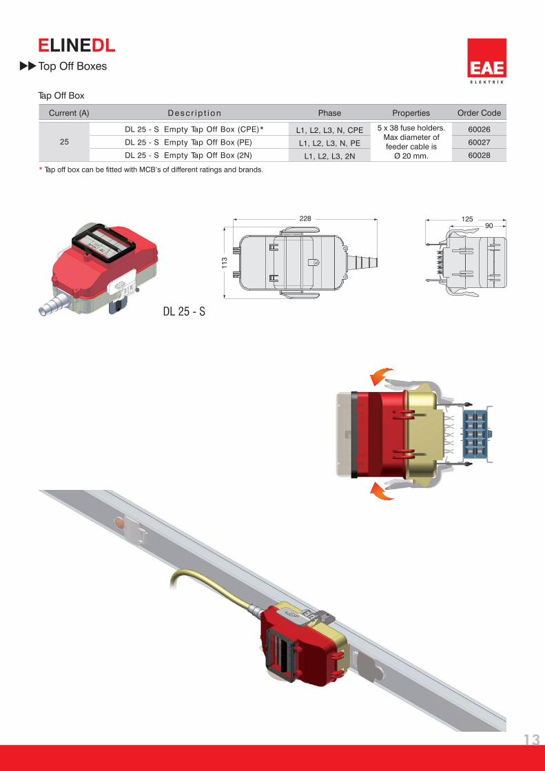
25
60026
60027
60028
L1, L2, L3, N, CPE
L1, L2, L3, N, PE
2L1, L2, L3, N
DL 25 - S
2281
13
12590
Top Off Boxes
Tap Off Box
* Tap off box can be fitted with MCB’s of different ratings and brands.
Current (A)
DL 25 S
DL 25 S (PE)
DL 25 - S (2N)
-
-
Empty Tap Off Box (CPE)*
Empty Tap Off Box
Empty Tap Off Box
D es c r ip t io n Order CodePropertiesPhase
5 x 38 fuse holders.
Max diameter of
feeder cable is
Ø 20 mm.

14
E L E K T R İ K
E DLLINE
72535
92
5619DL-TP
98699
55
4020
ø 7,5
Fixing
Order CodeD es c r ip t io n
Order CodeD es c r ip t io n
KA - TPU Fixing unit “U” type
DL Fixing Unit

15
E L E K T R İ K
E DLLINE
80
3037
ø 7,5
98525
95
3540
ø 9
ø 12
98698
Fixing
KA - TP Lighting fixture fixing unit
KA-TPL Fixing unit “L” type
D es c r ip t io n
D es c r ip t io n
Order Code
Order Code
1
1a
16
E L E K T R İ K
E DLLINE
3
2
4
CLICK
3a
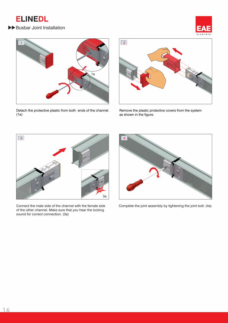
Busbar Joint Installation
Connect the male side of the channel with the female side
of the other channel. Make sure that you hear the locking
sound for correct connection. (3a)
Complete the joint assembly by tightening the joint bolt. (4a)
Detach the protective plastic from both ends of the channel.(1a)
Remove the plastic protective covers from the system
as shown in the figure.

17
E L E K T R İ K
E DLLINE
2
4a 4b
4
3
1
2a
DL Tap Off Plug Fixing
Turn the locking button on the busbar to OPEN ( )
position (Figure 1).
Turn the locking knob to OPEN ( )position.
Clips are open now. Insert the plug while aligning
contacts correctly to the busbar (Figure 2 & 3).
After fixing the plug to the busbar properly, turn the locking
knob to LOCK ( ) position as shown on
(Figure 4).

18
E L E K T R İ K
E DLLINEDirective
EC DECLARATION OF CONFORMITY
E L E K T R İ K
EAE Elektrik A.S.
Product Group
Standar :d
Manufacturer
E-Line DL Busbar Energy Distribution System
IEC 60439-1
IEC 60439-2
EAE Elektrik Asansor End. Insaat San. ve Tic. A.S.
Akcaburgaz Mahallesi, 119. Sokak, No:10 34510 Esenyurt-Istanbul-Turkey
Tel: +90 (212) 866 20 00 Fax: +90 (212) 886 24 20 http://www.eae.com.tr
EAE Elektrik Asansor End. Insaat San. ve Tic. A.S.
Akcaburgaz Mahallesi, 119. Sokak,
No:10 34510 Esenyurt-Istanbul
This is to attest, under our sole responsibility, that the aforementioned products conforms with
the regulations and guidelines of the following standards.
Date
09 January 2008
According to EC - Directive
2006/95/EEC “Low - Voltage - Directive”
Type Tests
1- Temperature Rise
2- Dielectric Characteristics
3- Short Circuit Resistance
4- Continuity of the Protective Circuit
5- Creepage Distances
6- Mechanical Operation
7- Protection Class
8- Electrical Characteristics
9- Structural Strength
10- Crush Strength
11- Insulation Material Thermal Strength
E L E K T R İ K
E DLLINE
19
E L E K T R İ K
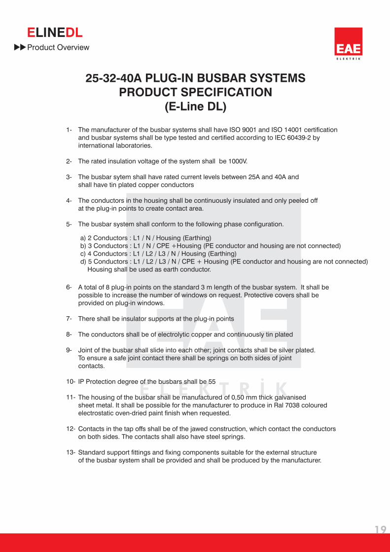
25-32-40A PLUG-IN BUSBAR SYSTEMS
PRODUCT SPECIFICATION
(E-Line DL)
Product Overview
1-
2-
3-
4-
5-
6-
7-
8-
9-
10-
11-
12-
13-
The manufacturer of the busbar systems shall have ISO 9001 and ISO 14001 certification
and busbar systems shall be type tested and certified according to IEC 60439-2 by
international laboratories.
The rated insulation voltage of the system shall be 1000V.
The busbar sytem shall have rated current levels between 25A and 40A and
shall have tin plated copper conductors
The conductors in the housing shall be continuously insulated and only peeled off
at the plug-in points to create contact area.
The busbar system shall conform to the following phase configuration.
a) 2 Conductors : L1 / N / Housing (Earthing)
b) 3 Conductors : L1 / N / CPE +Housing (PE conductor and housing are not connected)
c) 4 Conductors : L1 / L2 / L3 / N / Housing (Earthing)
d) 5 Conductors : L1 / L2 / L3 / N / CPE + Housing (PE conductor and housing are not connected)
Housing shall be used as earth conductor.
A total of 8 plug-in points on the standard 3 m length of the busbar system. It shall be
possible to increase the number of windows on request. Protective covers shall be
provided on plug-in windows.
There shall be insulator supports at the plug-in points
The conductors shall be of electrolytic copper and continuously tin plated
Joint of the busbar shall slide into each other; joint contacts shall be silver plated.
To ensure a safe joint contact there shall be springs on both sides of joint
contacts
IP Protection degree of the busbars shall be 55
The housing of the busbar shall be manufactured of 0,50 mm thick galvanised
sheet metal. It shall be possible for the manufacturer to produce in Ral 7038 coloured
electrostatic oven-dried paint finish when requested.
Contacts in the tap offs shall be of the jawed construction, which contact the conductors
on both sides. The contacts shall also have steel springs.
Standard support fittings and fixing components suitable for the external structure
of the busbar system shall be provided and shall be produced by the manufacturer.
.

20
E L E K T R İ K
E DLLINEQ
uantit
yC
om
po
nen
t
Co
mp
on
en
t Lis
t
Item
Project Design Form
Ple
ase d
ub
licate
th
is p
ag
e fo
r yo
ur
ow
n u
se.
Nam
e:
Date
:
Sig
natu
re:
Prepared by
Co
mp
an
y:
Pro
ject
:
Pro
ject
No
: