MS_uC / fue1 / V01 6- 1 TIMx - Timer Programming Microcontroller TIMx - Timer Autumn term 2012.
Upload
vernon-fildesCategory
view
226download
1
3- 1
RTC - Real Time Clock
MS_uC / dnd / V08
Programming MicrocontrollerCAN – Analog Digital Converter
Autumn term 2008
32K Byte 32K Byte Burst FlashBurst Flash
64K or 96K 64K or 96K Byte SRAM Byte SRAM
256K or 512K 256K or 512K Byte Burst Byte Burst
FlashFlash
OTP OTP MemMem
UARTUARTI2CI2CSPISPITIMTIMRTCRTC
EXT. EXT. Bus Bus
GPIOGPIO
USB USB 2.0FS 2.0FS
CAN CAN 2.0B 2.0B
Enet Enet MAC MAC
PFPFQ Q
BC BC
DMADMA
INTINTR R
CntlCntl
ARM96ARM966E 6E CORE CORE
w/DSPw/DSP96 MHz 96 MHz
CLK CLK CntlCntl
ADCADC
LVD LVD BODBOD
PLLPLL JTAJTAGG
ETMETM99
STR912FW44
3- 2
RTC - Real Time Clock
MS_uC / dnd / V08
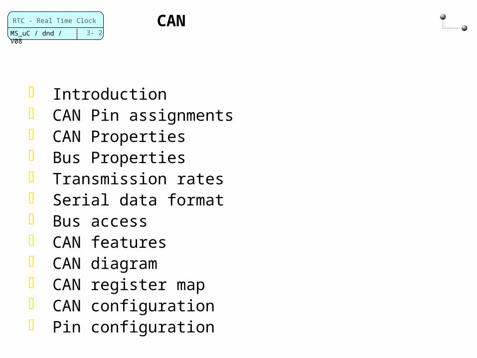
CAN
Introduction CAN Pin assignments CAN Properties Bus Properties Transmission rates Serial data format Bus access CAN features CAN diagram CAN register map CAN configuration Pin configuration

3- 3
RTC - Real Time Clock
MS_uC / dnd / V08
CAN (Controller Area Network) has been developed in 1981 Robert Bosch GmbH and Intel
CAN was originally planed for the car industry CAN is also established in the automation and medicinal industry
The CiA (CAN in Automation) has defined many industrial standards www.can‑cia.org
Introduction
3- 4
RTC - Real Time Clock
MS_uC / dnd / V08
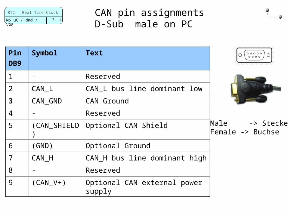
CAN pin assignmentsD-Sub male on PC
PinDB9
Symbol Text
1 - Reserved
2 CAN_L CAN_L bus line dominant low
3 CAN_GND CAN Ground
4 - Reserved
5 (CAN_SHIELD)
Optional CAN Shield
6 (GND) Optional Ground
7 CAN_H CAN_H bus line dominant high
8 - Reserved
9 (CAN_V+) Optional CAN external power supply
Male -> SteckerFemale -> Buchse
3- 5
RTC - Real Time Clock
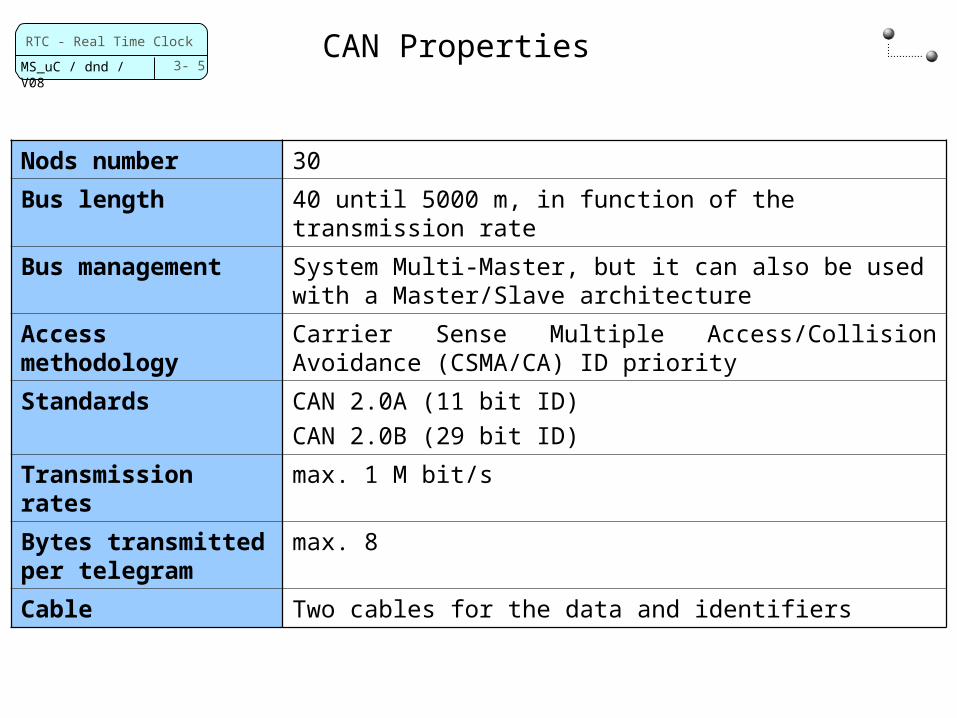
MS_uC / dnd / V08CAN Properties
Nods number 30
Bus length 40 until 5000 m, in function of the transmission rate
Bus management System Multi-Master, but it can also be used with a Master/Slave architecture
Access methodology
Carrier Sense Multiple Access/Collision Avoidance (CSMA/CA) ID priority
Standards CAN 2.0A (11 bit ID)CAN 2.0B (29 bit ID)
Transmission rates
max. 1 M bit/s
Bytes transmitted per telegram
max. 8
Cable Two cables for the data and identifiers

3- 6
RTC - Real Time Clock
MS_uC / dnd / V08
BUS properties
The data are transmitted in a differential way Reduction of the ambiance noise
The bus contains the following levels Dominant (logical low level) Recessive (logical high level)
CAN-L (Dominant low)
CAN-H (Dominant high)
CAN Node 1
CAN Node 2
12
0
12
0
3- 7
RTC - Real Time Clock
MS_uC / dnd / V08
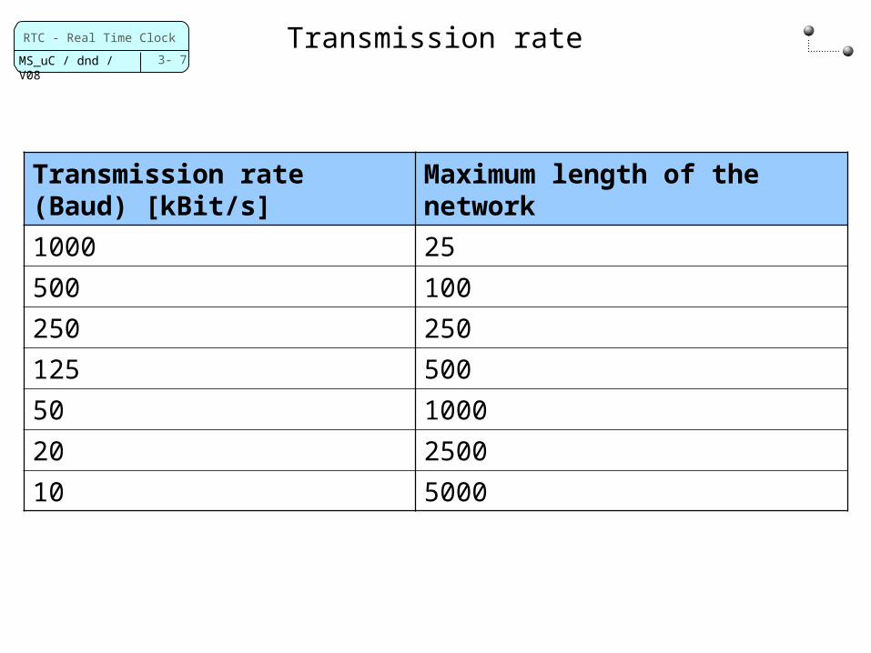
Transmission rate
Transmission rate (Baud) [kBit/s]
Maximum length of the network
1000 25
500 100
250 250
125 500
50 1000
20 2500
10 5000
3- 8
RTC - Real Time Clock
MS_uC / dnd / V08
SO
F
Ident
RT
R
IDE
r0
DLC Data CRC
arbitration field
control field
data field CRC field
ack field
AC
K
EOF IFS
11 0..64 15 7 3 4
Bus idle
Bus idle
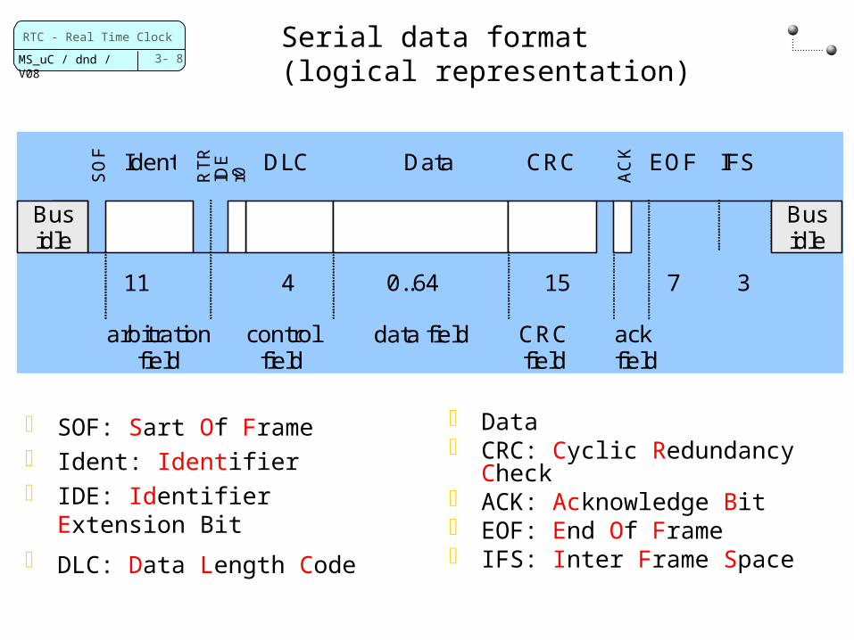
Serial data format (logical representation)
SOF: Sart Of Frame Ident: Identifier IDE: Identifier Extension Bit
DLC: Data Length Code
Data CRC: Cyclic Redundancy
Check ACK: Acknowledge Bit EOF: End Of Frame IFS: Inter Frame Space
3- 9
RTC - Real Time Clock
MS_uC / dnd / V08
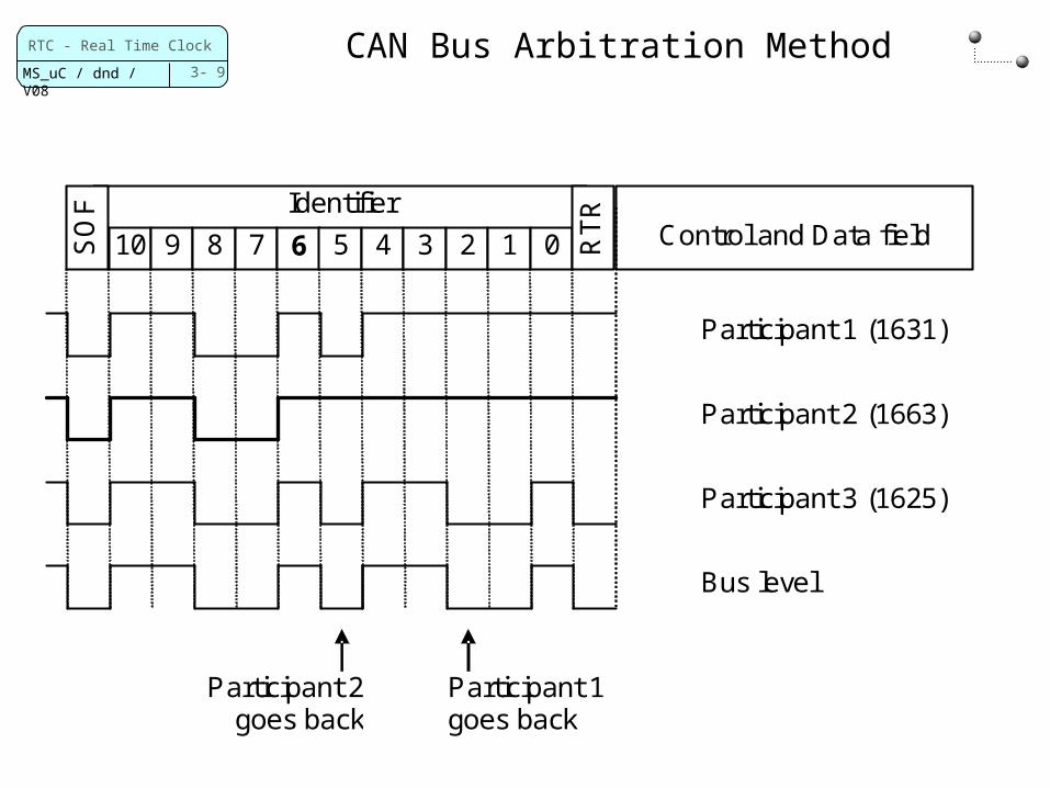
CAN Bus Arbitration Method
Identifier
SO
F
10 9 8 7 6 5 4 3 2 1 0 RT
R
Control and Data field
Participant 1 (1631)
Participant 2 (1663)
Participant 3 (1625)
Bus level
Participant 2 goes back
Participant 1 goes back

3- 10
RTC - Real Time Clock
MS_uC / dnd / V08
CAN features
Support CAN protocol version 2.0 part A and B Bit rates up to 1 MBits/s 32 Message Objects Each Message Object has its own identifier mask Programmable FIFO Mask able interrupt Disable Automatic Re-Transmission mode for Timer
Triggered CAN applications Programmable loop-back mode for test operation Two 16-bit module interfaces to the APB bus
3- 11
RTC - Real Time Clock
MS_uC / dnd / V08
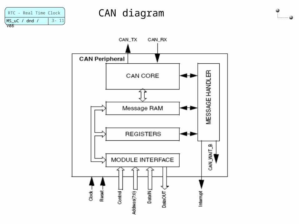
CAN diagram
3- 12
RTC - Real Time Clock
MS_uC / dnd / V08
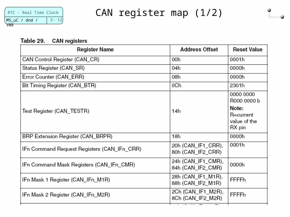
CAN register map (1/2)
3- 13
RTC - Real Time Clock
MS_uC / dnd / V08
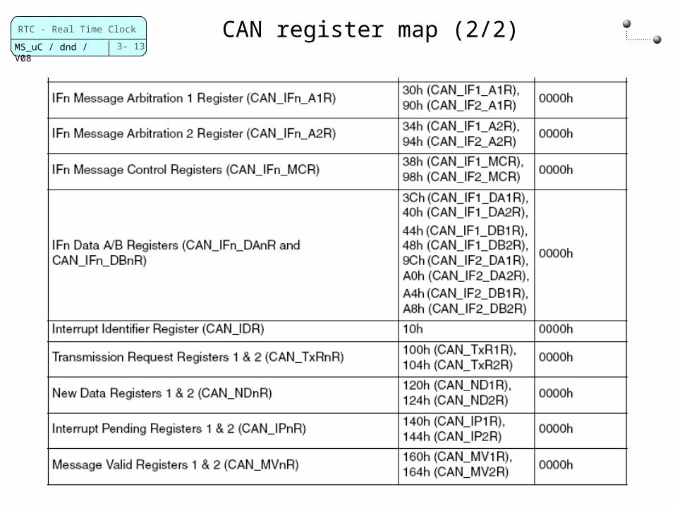
CAN register map (2/2)
3- 14
RTC - Real Time Clock
MS_uC / dnd / V08
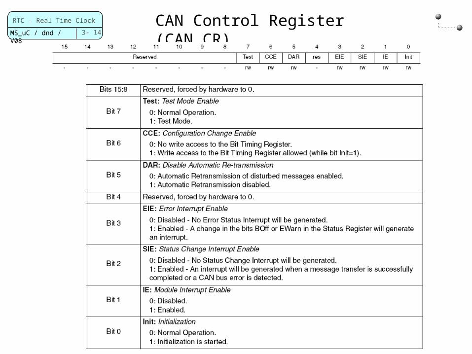
CAN Control Register (CAN_CR)
3- 15
RTC - Real Time Clock
MS_uC / dnd / V08
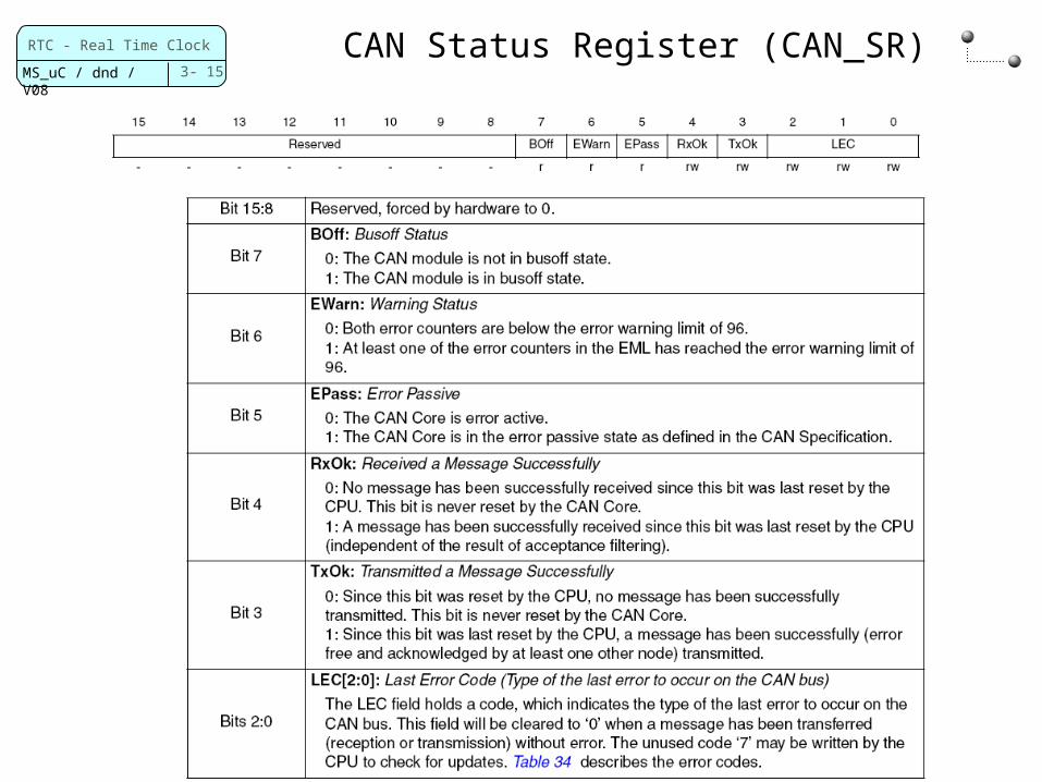
CAN Status Register (CAN_SR)
3- 16
RTC - Real Time Clock
MS_uC / dnd / V08
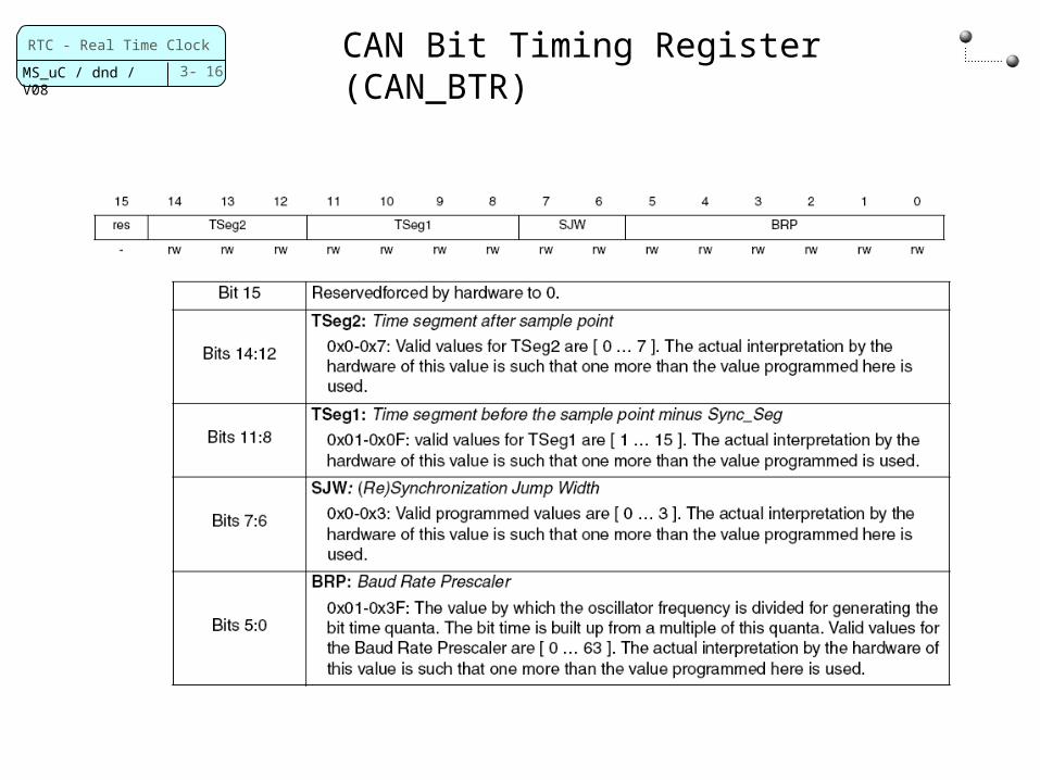
CAN Bit Timing Register (CAN_BTR)
3- 17
RTC - Real Time Clock
MS_uC / dnd / V08
CAN Configuration (1/2)
Configure the operating mode Register: CAN_CR The library function: CAN_Init
Structure variable member: CAN_ConfigParameters
Configure the bit rate Register: CAN_BTR The library function: CAN_Init
Structure variable member: CAN_Bitrate
Configure the transmit and receive messages Message interface register sets The bibliotheca functions
CAN_SetTxMsgObj and CAN_SetRxMsgObj
3- 18
RTC - Real Time Clock
MS_uC / dnd / V08
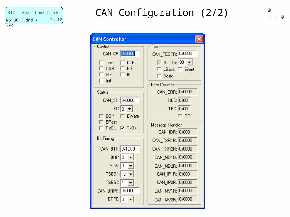
CAN Configuration (2/2)

3- 19
RTC - Real Time Clock
MS_uC / dnd / V08
Pin connections of CAN (1/2)
STR91x ARM966 manual 12274.pdf, 4.1 pin functions page 36
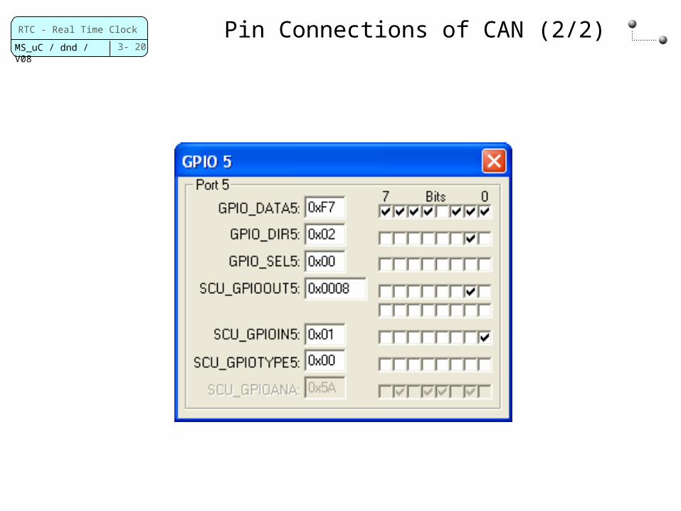
P5.0 CAN_RX Alternate Input 1P5.1 CAN_TX Alternate Output 2
Use CAN port of MCBSTR9. Which port?
3- 20
RTC - Real Time Clock
MS_uC / dnd / V08
Pin Connections of CAN (2/2)