
MSE307 Engineering Alloys 2014-15 L5: Phase Metallurgy of Titanium Alloys · 2015-02-15 · MSE307...
8
MSE307 Engineering Alloys 2014-15 L5: Phase Metallurgy of Titanium Alloys D. Dye a a Rm G03b, Department of Materials, Imperial College London, London SW7 2AZ, UK. [email protected] We turn now to a four-lecture primer on titanium al- loys. We will focus on titanium alloys for high integrity aerospace applications, but will pause briefly towards the end to consider commercially pure (CP) titanium in chem- ical plant, armour applications and biomedical alloys. The first two lectures focus on the phases and the generation of microstructures through processing, whilst the second two lectures consider mechanical behaviour and fatigue phe- nomena. For books, the following are recommended 1. L¨ utjering and Williams. Titanium, Springer, 2007. 2. Collings. The physical metallurgy of titanium alloys, ASM, 1984. 3. Donachie, Titanium: A technical guide, ASM, 2000. The primary reference is L¨ utiering and Williams. All three books are in the library. 5.1. Production of titanium from the oxide Titanium is produced by the Kroll Process, in which titanium tetrachloride is reduced by magnesium. TiO 2 is the 4th most abundant metallic element in the earth’s crust and is usually mined from sand deposits, e.g. in Australia. It is widely used for pigment in everything from paint to cosmetics and so refined white TiO 2 powder is cheap and extremely common. The TiO 2 is then reacted with carbon in chlorine gas; TiO 2 + 2Cl 2 + C/2C → TiCl 4 + CO 2 /2CO (1) This is performed in a fluidised bed; the inclusion of carbon in the process acts to provide a thermodynamic boost, reducing the amount of heat that must be supplied. This is more efficient from a CO 2 standpoint than burning fossil fuels in power stations or using natural gas to heat the reaction vessel, and will continue to be so until a CO 2 - free source of power is available. The product TiCl 4 is gaseous (boiling point 136 ◦ C and so the opportunity is taken to purify the titanium tetrachloride of other metal and titanium chlorides using fractional distillation. The Kroll process, Figure 1, then reduces this product using flowing magnesium metal at around 800-850 ◦ C; TiCl 4 + 2Mg → Ti + 2MgCl 2 (2) The magnesium chloride salt is then electrolysed to pro- duce Mg and Cl 2 , which are then recycled to make a closed- loop process. The Mg is mostly tapped off during the re- duction run. At the end of the Kroll process, the Mg and Figure 1: (Top) Schematic of a fluidised bed chlorinator for the pro- duction of TiCl 4 . (Bottom) Schematic of a Kroll reaction vessel (left), together with (right) a second Kroll vessel for collection of the Mg and MgCl 2 that are removed during vacuum distillation after the main Kroll reduction run. From L¨ utiering and Williams, Figures 3.1 and 3.3. MgCl 2 are separated by vacuum distillation. The product Ti is a porous, partially sintered ‘sponge’ of titanium, Fig- ure 2. It is manually subdivided and crushed to produce particles a few cm in size. As discussed in the melting and forging lecture, the sponge is then crushed and consolidated into briquettes, which are melted by vacuum arc remelting (VAR), Fig- ure 3. The VAR ingot is then remelted a further two times, prior to breakdown forging to reduce the β phase grain size, followed finally by finish forging, usually in the α + β phase field. In practice, there are usually substan- tially more forging steps than this, but this is an adequate simplified description of the processing. The Kroll process costs about 125 MWhr/tonne, or about £4/kg at 2003 prices just in power. The production cost is around £6/kg, although the market prices fluc- tuates significantly depending on market conditions. Over Lecture Notes for MSE307 February 15, 2015
Transcript of MSE307 Engineering Alloys 2014-15 L5: Phase Metallurgy of Titanium Alloys · 2015-02-15 · MSE307...
MSE307 Engineering Alloys 2014-15 L5: Phase Metallurgy of Titanium Alloys
D. Dyea
aRm G03b, Department of Materials, Imperial College London, London SW7 2AZ, UK. [email protected]
We turn now to a four-lecture primer on titanium al-loys. We will focus on titanium alloys for high integrityaerospace applications, but will pause briefly towards theend to consider commercially pure (CP) titanium in chem-ical plant, armour applications and biomedical alloys. Thefirst two lectures focus on the phases and the generation ofmicrostructures through processing, whilst the second twolectures consider mechanical behaviour and fatigue phe-nomena. For books, the following are recommended
1. Lutjering and Williams. Titanium, Springer, 2007.2. Collings. The physical metallurgy of titanium alloys,
ASM, 1984.3. Donachie, Titanium: A technical guide, ASM, 2000.
The primary reference is Lutiering and Williams. All threebooks are in the library.
5.1. Production of titanium from the oxide
Titanium is produced by the Kroll Process, in whichtitanium tetrachloride is reduced by magnesium. TiO2
is the 4th most abundant metallic element in the earth’scrust and is usually mined from sand deposits, e.g. inAustralia. It is widely used for pigment in everything frompaint to cosmetics and so refined white TiO2 powder ischeap and extremely common. The TiO2 is then reactedwith carbon in chlorine gas;
TiO2 + 2Cl2 + C/2C→ TiCl4 + CO2/2CO (1)
This is performed in a fluidised bed; the inclusion of carbonin the process acts to provide a thermodynamic boost,reducing the amount of heat that must be supplied. Thisis more efficient from a CO2 standpoint than burning fossilfuels in power stations or using natural gas to heat thereaction vessel, and will continue to be so until a CO2-free source of power is available. The product TiCl4 isgaseous (boiling point 136◦C and so the opportunity istaken to purify the titanium tetrachloride of other metaland titanium chlorides using fractional distillation.
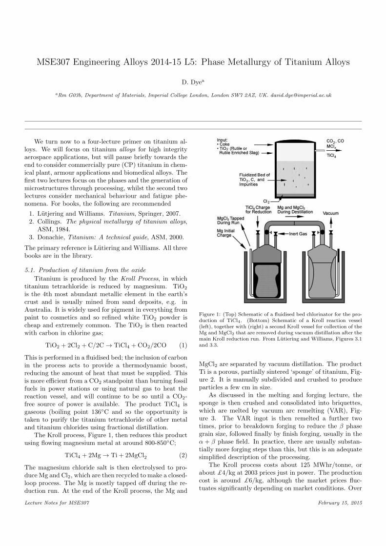
The Kroll process, Figure 1, then reduces this productusing flowing magnesium metal at around 800-850◦C;
TiCl4 + 2Mg→ Ti + 2MgCl2 (2)
The magnesium chloride salt is then electrolysed to pro-duce Mg and Cl2, which are then recycled to make a closed-loop process. The Mg is mostly tapped off during the re-duction run. At the end of the Kroll process, the Mg and
Figure 1: (Top) Schematic of a fluidised bed chlorinator for the pro-duction of TiCl4. (Bottom) Schematic of a Kroll reaction vessel(left), together with (right) a second Kroll vessel for collection of theMg and MgCl2 that are removed during vacuum distillation after themain Kroll reduction run. From Lutiering and Williams, Figures 3.1and 3.3.
MgCl2 are separated by vacuum distillation. The productTi is a porous, partially sintered ‘sponge’ of titanium, Fig-ure 2. It is manually subdivided and crushed to produceparticles a few cm in size.
As discussed in the melting and forging lecture, thesponge is then crushed and consolidated into briquettes,which are melted by vacuum arc remelting (VAR), Fig-ure 3. The VAR ingot is then remelted a further twotimes, prior to breakdown forging to reduce the β phasegrain size, followed finally by finish forging, usually in theα + β phase field. In practice, there are usually substan-tially more forging steps than this, but this is an adequatesimplified description of the processing.
The Kroll process costs about 125 MWhr/tonne, orabout £4/kg at 2003 prices just in power. The productioncost is around £6/kg, although the market prices fluc-tuates significantly depending on market conditions. Over
Lecture Notes for MSE307 February 15, 2015
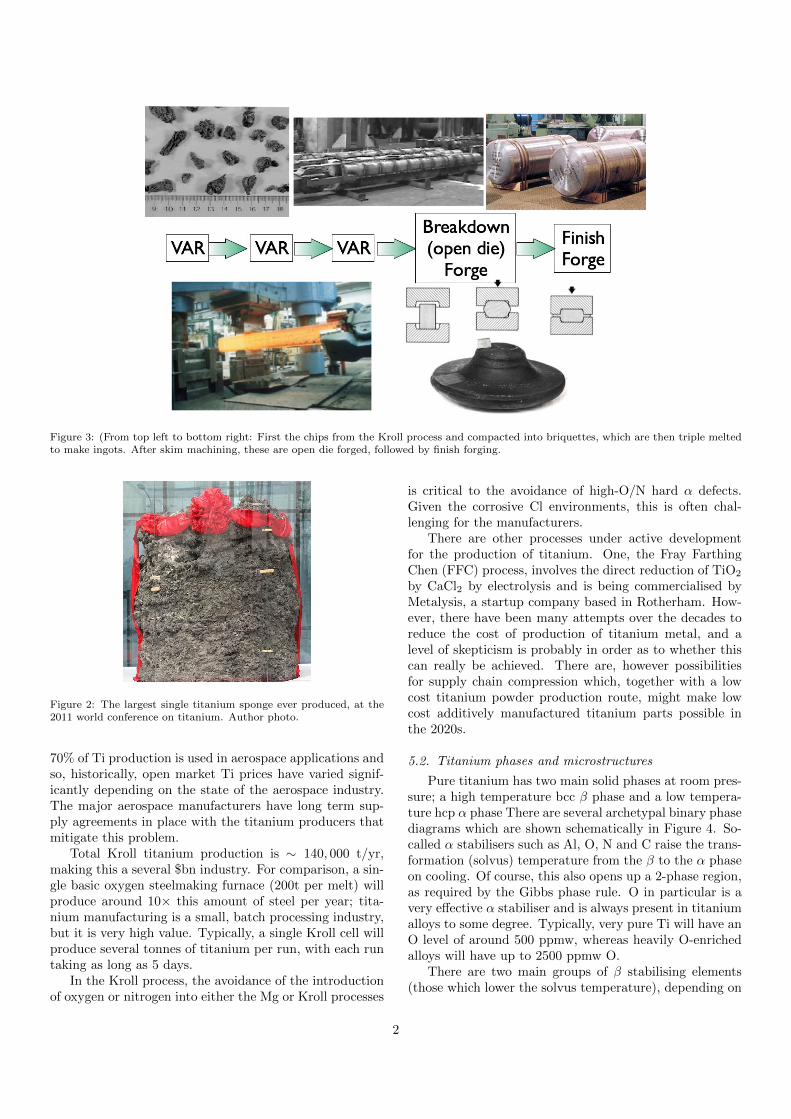
Figure 3: (From top left to bottom right: First the chips from the Kroll process and compacted into briquettes, which are then triple meltedto make ingots. After skim machining, these are open die forged, followed by finish forging.
Figure 2: The largest single titanium sponge ever produced, at the2011 world conference on titanium. Author photo.
70% of Ti production is used in aerospace applications andso, historically, open market Ti prices have varied signif-icantly depending on the state of the aerospace industry.The major aerospace manufacturers have long term sup-ply agreements in place with the titanium producers thatmitigate this problem.
Total Kroll titanium production is ∼ 140, 000 t/yr,making this a several $bn industry. For comparison, a sin-gle basic oxygen steelmaking furnace (200t per melt) willproduce around 10× this amount of steel per year; tita-nium manufacturing is a small, batch processing industry,but it is very high value. Typically, a single Kroll cell willproduce several tonnes of titanium per run, with each runtaking as long as 5 days.
In the Kroll process, the avoidance of the introductionof oxygen or nitrogen into either the Mg or Kroll processes
is critical to the avoidance of high-O/N hard α defects.Given the corrosive Cl environments, this is often chal-lenging for the manufacturers.
There are other processes under active developmentfor the production of titanium. One, the Fray FarthingChen (FFC) process, involves the direct reduction of TiO2
by CaCl2 by electrolysis and is being commercialised byMetalysis, a startup company based in Rotherham. How-ever, there have been many attempts over the decades toreduce the cost of production of titanium metal, and alevel of skepticism is probably in order as to whether thiscan really be achieved. There are, however possibilitiesfor supply chain compression which, together with a lowcost titanium powder production route, might make lowcost additively manufactured titanium parts possible inthe 2020s.
5.2. Titanium phases and microstructures
Pure titanium has two main solid phases at room pres-sure; a high temperature bcc β phase and a low tempera-ture hcp α phase There are several archetypal binary phasediagrams which are shown schematically in Figure 4. So-called α stabilisers such as Al, O, N and C raise the trans-formation (solvus) temperature from the β to the α phaseon cooling. Of course, this also opens up a 2-phase region,as required by the Gibbs phase rule. O in particular is avery effective α stabiliser and is always present in titaniumalloys to some degree. Typically, very pure Ti will have anO level of around 500 ppmw, whereas heavily O-enrichedalloys will have up to 2500 ppmw O.
There are two main groups of β stabilising elements(those which lower the solvus temperature), depending on
2
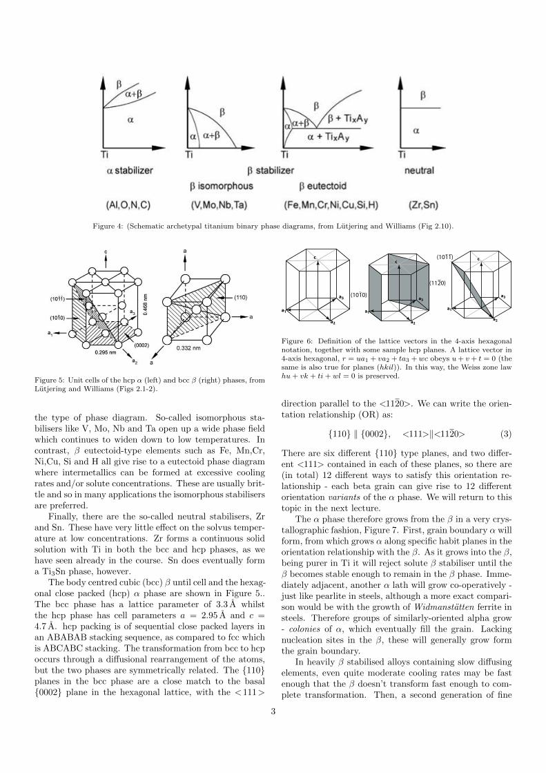
Figure 4: (Schematic archetypal titanium binary phase diagrams, from Lutjering and Williams (Fig 2.10).
Figure 5: Unit cells of the hcp α (left) and bcc β (right) phases, fromLutjering and Williams (Figs 2.1-2).
the type of phase diagram. So-called isomorphous sta-bilisers like V, Mo, Nb and Ta open up a wide phase fieldwhich continues to widen down to low temperatures. Incontrast, β eutectoid-type elements such as Fe, Mn,Cr,Ni,Cu, Si and H all give rise to a eutectoid phase diagramwhere intermetallics can be formed at excessive coolingrates and/or solute concentrations. These are usually brit-tle and so in many applications the isomorphous stabilisersare preferred.
Finally, there are the so-called neutral stabilisers, Zrand Sn. These have very little effect on the solvus temper-ature at low concentrations. Zr forms a continuous solidsolution with Ti in both the bcc and hcp phases, as wehave seen already in the course. Sn does eventually forma Ti3Sn phase, however.
The body centred cubic (bcc) β until cell and the hexag-onal close packed (hcp) α phase are shown in Figure 5..The bcc phase has a lattice parameter of 3.3 A whilstthe hcp phase has cell parameters a = 2.95 A and c =4.7 A. hcp packing is of sequential close packed layers inan ABABAB stacking sequence, as compared to fcc whichis ABCABC stacking. The transformation from bcc to hcpoccurs through a diffusional rearrangement of the atoms,but the two phases are symmetrically related. The {110}planes in the bcc phase are a close match to the basal{0002} plane in the hexagonal lattice, with the <111>
a1
c
a2
a3
a1
c
a2
a3(1010)
(1120)
a1
c
a2
a3
(1011)
Figure 6: Definition of the lattice vectors in the 4-axis hexagonalnotation, together with some sample hcp planes. A lattice vector in4-axis hexagonal, r = ua1 + va2 + ta3 +wc obeys u+ v+ t = 0 (thesame is also true for planes (hkil)). In this way, the Weiss zone lawhu+ vk + ti+ wl = 0 is preserved.
direction parallel to the <1120>. We can write the orien-tation relationship (OR) as:
{110} ‖ {0002}, <111>‖<1120> (3)
There are six different {110} type planes, and two differ-ent <111> contained in each of these planes, so there are(in total) 12 different ways to satisfy this orientation re-lationship - each beta grain can give rise to 12 differentorientation variants of the α phase. We will return to thistopic in the next lecture.
The α phase therefore grows from the β in a very crys-tallographic fashion, Figure 7. First, grain boundary α willform, from which grows α along specific habit planes in theorientation relationship with the β. As it grows into the β,being purer in Ti it will reject solute β stabiliser until theβ becomes stable enough to remain in the β phase. Imme-diately adjacent, another α lath will grow co-operatively -just like pearlite in steels, although a more exact compari-son would be with the growth of Widmanstatten ferrite insteels. Therefore groups of similarly-oriented alpha grow- colonies of α, which eventually fill the grain. Lackingnucleation sites in the β, these will generally grow formthe grain boundary.
In heavily β stabilised alloys containing slow diffusingelements, even quite moderate cooling rates may be fastenough that the β doesn’t transform fast enough to com-plete transformation. Then, a second generation of fine
3
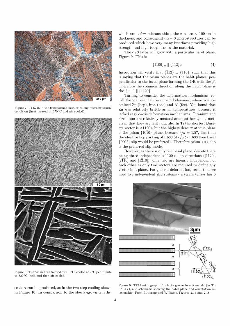
Figure 7: Ti-6246 in the transformed beta or colony microstructuralcondition (heat treated at 970◦C and air cooled).
Figure 8: Ti-6246 in heat treated at 910◦C, cooled at 2◦C per minuteto 820◦C, held and then air cooled.
scale α can be produced, as in the two-step cooling shownin Figure 10. In comparison to the slowly-grown α laths,
which are a few microns thick, these α are < 100 nm inthickness, and consequently α− β microstructures can beproduced which have very many interfaces providing highstrength and high toughness to the material.
The α/β laths will grow with a particular habit plane,Figure 9. This is
{1100}α ‖ {112}β (4)
Inspection will verify that {112} ⊥ {110}, such that thisis saying that the prism planes are the habit planes, per-pendicular to the basal plane forming the OR with the β.Therefore the common direction along the habit plane isthe {111} ‖ {1120}.
Turning to consider the deformation mechanisms, re-call the 2nd year lab on impact behaviour, where you ex-amined Zn (hcp), iron (bcc) and Al (fcc). You found thatZn was relatively brittle as all temperatures, because itlacked easy c-axis deformation mechanisms. Titanium andzirconium are relatively unusual amongst hexagonal met-als in that they are fairly ductile. In Ti the shortest Burg-ers vector is <1120> but the highest density atomic planeis the prism {1010} plane, because c/a = 1.57, less thanthe ideal for hcp packing of 1.633 (if c/a > 1.633 then basal{0002} slip would be preferred). Therefore prism <a> slipis the preferred slip mode.
However, as there is only one basal plane, despite therebeing three independent <1120> slip directions ([1120],[2110] and [1210]), only two are linearly independent ofeach other as only two vectors are required to define anyvector in a plane. For general deformation, recall that weneed five independent slip systems - a strain tensor has 6
Figure 9: TEM micrograph of α laths grown in a β matrix (in Ti-6Al-4V), and schematic showing the habit plane and orientation re-lationship. From Lutiering and Williams, Figures 2.17 and 2.18.
4

independent components, the hydrostatic strain plus fiveshape changes that can be realised by plasticity (von Misescriterion). Therefore we need three further slip systemsinvolving c-axis deformation in order for our hexagonalcrystal to be ductile.
In commercially pure titanium these are provided bytwinning, but the conventional wisdom is that alloying α-Ti with Al promotes c+ a slip at the expense of twinning,and for this reason nearly all commercial Ti alloys contain∼ 6 wt.% Al. Nevertheless, micro twins are still sometimesobserved in alloyed α-Ti, and some workers suggest thattwinning may occur during the hot forming of titaniumalloys.
For a grain oriented with its c-axis along the loadingaxis, both <a> and pure <c> slip would have zero Schmidfactor, and so the additional slip systems must be providedby <c+a> slip. For the same reason, the slip plane cannotbe the {1010}, and so the actual operative slip mode isfound to be the < 1123> {1122} - this being preferredto the {1011} as this slip plane is closer to 45◦ from thec-axis.
As the Burgers vector is greater and U = 12Gb
2, thispyramidal <c + a> slip has about 3× greater critical re-solved shear stress (CRSS) than prism <a> slip. Thisleads to the finding that only a few grains will actuallyundergo <c + a> slip, but these are vital to the ductilityof the alloy.
In β-Ti, the usual bcc slip systems of <111> along the{110}, {112} or {123} planes apply.
Therefore, titanium is quite plastically anisotropic; thereare hard-oriented and soft-oriented grains. In addition, ina lamellar structure, there will be one <1120>α that isnear parallel to a < 111>β (Figure yy), and so one di-
Type Slip Slip # Slip SystemsDirection Plane Total Independent
<a> <1120> {0002} 3 2<c+ a> <1123> {1122} 6 5
Table 1: Preferred slip modes in the hexagonal α phase.
Figure 10: Unit cell of the α phase showing the slip planes and slipdirections occurring. From Lutiering and Williams, Figure 2.6.
rection in which this composite is relatively permeable todislocations, whereas all other directions will be hard.
5.3. Binary phase diagrams
We turn now to look at some real binary phase dia-grams in the titanium system, Figure 11. First, Ti-Al isan alpha stabiliser and raises the β solvus temperature. Itdoesn’t however, ever give rise to a very wide two phaseα + β field - which is desired for forging operations. Inaddition, beyond about 6 or 7 wt.% Al (∼ 12 at.%), weenter the two phase α + α2-Ti3Al region at temperaturesof around 550–650◦C, which is sufficiently high that, atlong ageing times, α2 can form. This is significant as α2
formation is generally considered to be undesirable as itis thought to give rise to a loss in ductility and fatigueresistance, as we shall see later.
In addition, notice the γ−TiAl phase, which is the ba-sis for gamma titanium aluminides. These are being in-troduced into jet engine applications after more than 30years’ development as high temperature materials in the450-650◦C range, where they have better density-correctedstrengths than nickel superalloys but do not suffer fromproblems of burn resistance like titanium alloys. One issuein their development has been that the high temperatureequilibria around 1100-1200◦C with the α2 phase have benquite tricky to determine.
Turning to the Ti-Sn diagram, we see that Sn has al-most no effect on the β solvus, and so tin is termed a neu-tral stabiliser. Hence it is quite widely used in titaniumalloys for solution strengthening of the α phase. However,notice that there is a Ti3Sn phase. It is found that Snwill tend to segregate to the Al site in the TI3Al α2 phase,which we have already noted is usually undesirable. There-fore Sn levels in titanium alloys are usually limited to a fewwt.%.
Mo is the archetypal isomorphous β stabiliser, having adramatic effect on the β solvus temperature. Notice thatat low temperatures, because Mo is a slow diffuser, thebinary phase diagram is not provided. In addition, thesolubility of Mo in α-Ti is very small - which is why it isa strong β stabiliser.
Cr is occasionally used, along with Fe, as a cheaperalternative β stabiliser than Mo, and at a lower densitypenalty. However, these have β eutectoid phase diagrams.So, whilst Cr reduced the β solvus and has limited solu-bility in the β phase, there is a eutectoid with the α TiCr2phase. Therefore enough other β stabilisers - such as Mo -must also be included to stabilise the β phase to room tem-perature, suppressing formation of the intermetallic phase.
5.4. Beta stabilisation
A ready-reckoner exists for summing-up the overall ex-tent of β stabilisation that different β stabilisers contributein a complex alloy. This is based upon establishing howmuch of each element is required to stabilise the β phaseto room temperature on quenching model binary alloys,
5
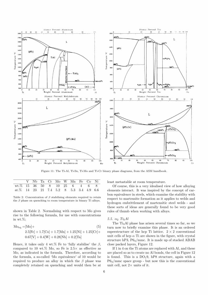
Figure 11: The Ti-Al, Ti-Sn, Ti-Mo and Ti-Cr binary phase diagrams, from the ASM handbook.
V Nb Ta Cr Mo W Mn Fe Co Niwt.% 15 36 50 8 10 25 6 4 6 8at.% 14 23 21 7.4 5.2 8 5.3 3.4 4.9 6.6
Table 2: Concentration of β stabilising elements required to retainthe β phase on quenching to room temperature in binary Ti alloys.
shown in Table 2. Normalising with respect to Mo givesrise to the following formula, for use with concentrationsin wt.%;
Moeq =[Mo]+ (5)
2.5[Fe] + 1.7[Co] + 1.7[Mn] + 1.25[Ni] + 1.25[Cr]+
0.67[V] + 0.4[W] + 0.28[Nb] + 0.2[Ta]
Hence, it takes only 4 wt.% Fe to ‘fully stabilise’ the β,compared to 10 wt.% Mo, so Fe is 2.5× as effective asMo, as indicated in the formula. Therefore, according tothe formula, a so-called ‘Mo equivalence’ of 10 would berequired to produce an alloy in which the β phase wascompletely retained on quenching and would then be at
least metastable at room temperature.Of course, this is a very idealised view of how alloying
elements interact. It was inspired by the concept of car-bon equivalence in steels, which examine the stability withrespect to martensite formation as it applies to welds andhydrogen embrittlement of martensitic steel welds - andthese sorts of ideas are generally found to be very goodrules of thumb when working with alloys.
5.5. α2 Ti3Al
The Ti3Al phase has arisen several times so far, so weturn now to briefly examine this phase. It is an orderedsuperstructure of the hcp Ti lattice. 2 × 2 conventionalunit cells of hcp α Ti are shown in the figure, with crystalstructure hP3, P63/mmc. It is made up of stacked ABABclose packed layers, Figure 12.
If 1 in 4 on the Ti atoms are replaced with Al, and theseare placed so as to create no Al bonds, the cell in Figure 12is found. This is a DO19, hP8 structure, again with aP63/mmc space group - but now this is the conventionalunit cell, not 2× units of it.
6
½
½
½ ½
½
½
½
½½
½
½
½
Figure 12: (Top) 2×2 of the hcp (A3 or hP3, P63/mmc) α Ti crystalstructure. (Bottom) A single conventional unit cell of the α2 crystalstructure (DO19 or hP8, again with P63/mmc).
Therefore it is possible to imagine taking α-Ti contain-ing 25 at.% Al, randomly distributed on the lattice, andobserving it order into the α2 lattice, without any long-scale diffusion taking place. Of course, in a real titaniumsuch high Al concentrations will not be found, and so toform α some clustering of the Al atoms must take placefor the α2 phase to form - a spinodal decomposition. Al-ternately, it might be possible for Ti of only 11 at.% Al toorder and form two sublattices - this topic is still a topicof current research. Either way, in alloys with > 8 wt.%Al, Ti3Al α2 formation has been observed many times.
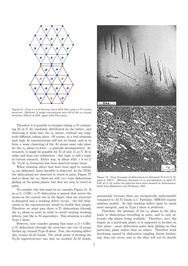
When titanium alloys that have been aged to containα2 are deformed, lower ductility is observed. In the TEM,the dislocations are observed to travel in pairs, Figure ??and to shear the α2; these are still <a>-type dislocationsgliding on the prism planes, but they are seen to travel inpairs.
To consider why this must be so, consider Figure 14. Ifan a/3 <1120> α-Ti dislocation is passed that moves theatoms on the central row in the figure, then the structureis disrupted and a stacking defect occurs - the full dislo-cation in the superstructure would be double that length.Therefore we must pass these α-Ti dislocations throughthe α2 phase in pairs in order to avoid creating stackingdefects, just like in Ni superalloys. This situation is calledType I shear.
However, now consider passing that same a/3 <1120>α-Ti dislocation through the structure one row of atomsfurther up, termed Type II shear. Now, the stacking defectalso creates Al-Al bonds. The whole point of forming theTi3Al superstructure was that we avoided Al-Al bonds,
Figure 13: (Top) Example of dislocations in deformed Ti-8 wt.% Al,aged at 500◦C. (Bottom) Example of α2 precipitation in aged Ti-8.65 wt.% Al, where the particles have been sheared by deformation.Both from Blakcburn and Williams, 1967.
presumably because these are energetically unfavourablecompared to Al-Ti bonds (c.f. Enthalpy, MSE104 regularsolution model). So this stacking defect must be muchmore energetic, and so Type I shear is preferred.
Therefore, the presence of the α2 phase in the alloyleads to dislocations travelling in pairs, and to only al-ternate slip planes being available. Therefore, once slipbegins on a particular plane, is is supposed to localise onthat plane - more dislocation pairs keep gliding on thatparticular plane rather than on others. Therefore workhardening caused by dislocation tangling (forest harden-ing) does not occur, and so the alloy will not be ductile
7

Figure 14: (Top) Type I and (Bottom) Type II shear in Ti3Al α2.Passing a single a/3 < 1120> α Ti dislocation creates a stackingdefect in each case, but in the case of Type II shear, where Al-Albonds are created, it is more more energetic.
according to Considere’s criterion. On the fracture plane,the fracture mechanism is observed to be microvoid coa-lescence and growth, not cleavage, but the lack of workhardening has given rise to strain localisation.
This is actually a general point; it is very important inengineering microstructures of materials at the nanoscalenot to create mechanisms by which the localisation of de-formation can occur. When it does, this generally leads toa catastrophic loss of ductility.
This mechanism is the reason why α2 phase formationis generally considered to be undesirable in titanium alloys.
5.6. Alpha stabilisation
Finally, there is a similar ready-reckoner for the degreeof alpha stabilisation of an alloy, the aluminium-equivalence(in wt.%);
Aleq = [Al] +1
6[Zr] +
1
3[Sn] + 10[O+C+2N] (6)
This equation, due to Rosenberg, attempts to focus on theeffect of α stabilisers on the solvus, but also the effect onthe α phase boundary. Notice that Sn, is includes, as whencombined with Al, it acts to stabilise the α phase, whilston its own it is neutral. Hence, there are limits to the util-ity of binary diagrams in understanding mutlicomponentsystems.
The other thing to notice in this equation is that Ois an extremely effective α stabiliser, which reinforces theproblem with the avoidance of hard α defects arising priorto melting.
Often, both α and β stabilisers will be used. Thisacts to increase the size of the α+ β phase field, wideningthe temperature interval over which α + β forging can beperformed. Of course, this also permits more solid solutionstrengthening to be utilised in each phase.
Generally, it is said that Zr, Hf and Sn raise the α/βtransformation temperature but do not affect the fractionvery much. It is said that the Al-equivalence should bekept below 10 to avoid the production of Ti3X hcp α2,but there are many exceptions to this guideline.
5.7. Summary
In this lecture we have introduced Ti alloys. We havefound that titanium is expensive and time consuming toproduce. It is truly a multi-$bn cottage industry, withonly a few suppliers in the world. The key feature of thephase metallurgy is the α/β phase transformation, whichdominates the microstructures produced. We have dividedthe alloying elements into β stabilisers (Mo,Fe and others),and α stabilisers (Al, O and friends), and we have hadan interesting discussion about the crystallography anddeformation mechanisms, and the effect of the α2 phase.
— END OF LECTURE —
8