MS-1762 Disassembly guide - MSI NotebookGT70(MS-1762)Disassembly Guide 3、HDD MODULE 3.1:...
27
GT70 (MS-1762) Disassembly Guide ■ 1、BATTERY PACK ■ 2、BOTTOM DOOR ASSY ■ 3、HDD MODULE ■ 4、THERMAL-KIT、CPU AND DRAM ■ 5、ODD MODULE ■ 6、SEPARATE UPPER CASE AND LOWER CASE ■ 7、LOWER CASE ASSY ■ 8、UPPER CASE ASSY ■ 9、LCD MODULE ASSY
Transcript of MS-1762 Disassembly guide - MSI NotebookGT70(MS-1762)Disassembly Guide 3、HDD MODULE 3.1:...

GT70 (MS-1762) Disassembly Guide
■ 1、BATTERY PACK
■ 2、BOTTOM DOOR ASSY
■ 3、HDD MODULE
■ 4、THERMAL-KIT、CPU AND DRAM
■ 5、ODD MODULE
■ 6、SEPARATE UPPER CASE AND LOWER CASE
■ 7、LOWER CASE ASSY
■ 8、UPPER CASE ASSY
■ 9、LCD MODULE ASSY

GT70(MS-1762)Disassembly Guide
1、BATTERY PACK
1.1:Move the “Unlock’ button base on left picture
shows.
1.2:Release the “Release” button and move the
battery pack base on left picture.
Component P/N Qty
Battery Pack S9N-3496200-M47 1

GT70(MS-1762)Disassembly Guide
2、BOTTOM DOOR ASSY
2.1:Remove the 12 screws (M2.5*7mm). Then
remove the Bottom door.
Attention: the screw driver touque is: 1.8-2.2 gf-cm
Component P/N Qty
Bottom door E2P-761J211-Y31 1
Screw E43-1257002-G68 12

GT70(MS-1762)Disassembly Guide
3、HDD MODULE
3.1: Remove the 4 screws (M2.5*5mm); then
remove the two HDD Module according to the
direction as pic shows.
Attention: the screw driver torque is 1.8-2.2Kgf-cm
Component P/N Qty
Screw E43-1255002-G68 4
3.2: Remove the 4 screws (M3*4mm) that stabilize
the two HDD brackets, then remove the HDD
bracket.
Attention: the screw driver torque is 1.8-2.2Kgf-cm
Component P/N Qty
Screw E43-1304009-G68 4
HDD Bracket 307-6F10112-C22 2
HDD Module S71-2475702-W36 2

GT70(MS-1762)Disassembly Guide
4、THERMAL-KIT、CPU AND DRAM
4.1: :Remove the 1 screw(M2.5*5mm) and FAN
cable, after that remove the Fan.
Attention:the screw driver torque is 1.8-2.2Kgf-cm
Component P/N Qty
Screw E43-1255002-G68 1
FAN E33-0800182-MC22 1
6
4.2: Remove the 3 screws (M2.5*5mm) and 4
spring screws, after that remove the two Heatsink.
Attention:the screw driver torque is 1.8-2.2Kgf-cm
Component P/N Qty
Screw E43-1255002-G68 3
Heatsink E31-0405764-Y31 1
Heatsink E31-0900332-TA9 1
4.3:Open the CPU Slot with Screw Driver, then
remove CPU Module as below.
Component P/N Qty
CPU A13-2320186-I06 1
4
72
1
56
3
GT70(MS-1762)Disassembly Guide
4、THERMAL-KIT、CPU AND DRAM
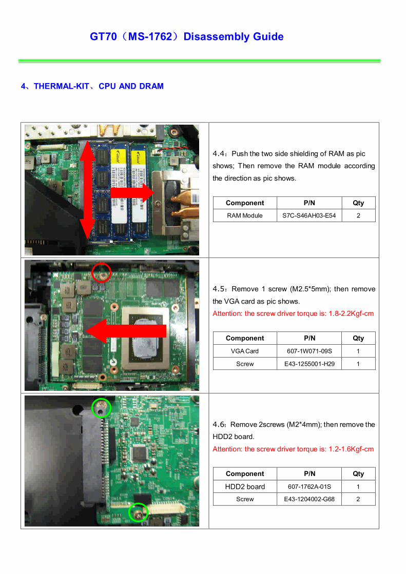
4.4:Push the two side shielding of RAM as pic
shows; Then remove the RAM module according
the direction as pic shows.
Component P/N Qty
RAM Module S7C-S46AH03-E54 2
4.5:Remove 1 screw (M2.5*5mm); then remove
the VGA card as pic shows.
Attention: the screw driver torque is: 1.8-2.2Kgf-cm
Component P/N Qty
VGA Card 607-1W071-09S 1
Screw E43-1255001-H29 1
4.6:Remove 2screws (M2*4mm); then remove the
HDD2 board.
Attention: the screw driver torque is: 1.2-1.6Kgf-cm
Component P/N Qty
HDD2 board 607-1762A-01S 1
Screw E43-1204002-G68 2

GT70(MS-1762)Disassembly Guide
5、ODD MODULE
5.1:Remove the ODD Module according to the
direction as pic shows.
5.2:Remove ODD Bezel as below.
Component P/N Qty
ODD Bezel E2P-761F212-Y31 1
5.3:Remove 2pcs (M2*3mm) Screws; Then remove
ODD Bracket as below.
Attention:the screw driver torque is 1.0-1.5Kgf-cm
Component P/N Qty
Screw E43-1203003-G68 2
ODD Bracket E2M-7611311-C22 1
ODD Module S7D-2270066-H44 1

GT70(MS-1762)Disassembly Guide
6、SEPARATE UPPER CASE AND LOWER CASE
6.1:Before remove K/B, firstly remove the Middle
Cover. Care the Sensor board FPC below the
cover. Remove the Sensor board
6.2:Remove the left and right hinge caps.
Component P/N Qty
Left Hinge cap E2P-7610222-Y31 1
Right Hinge cap E2P-7610321-Y31 1
6.3:Remove the LVDS cable as pic shows.

GT70(MS-1762)Disassembly Guide
6、SEPARATE UPPER CASE AND LOWER CASE
6.4:Remove MIC cable, then remove 1 screw
(M2*3mm); last remove the two side wireless card
antenna as pic shows.
Attention: the screw driver torque is: 1.8-2.2Kgf-cm
Component P/N Qty
WLAN Module S57-08000C0-I06 1
Screw E43-1203003-G68 1
6.5 : Remove the 2 screws (M2.5*7mm) that
stabilize the left LCD hinge.
Attention: the screw driver torque is 3.0-3.5Kgf-cm
Component P/N Qty
Screw E43-1257002-G68 2
6.6 : Remove the 2screws (M2.5*7mm) that
stabilize the right LCD hinge.
Attention: the screw driver torque is 3.0-3.5Kgf-cm
Component P/N Qty
Screw E43-1257002-G68 2
MIC Cable

GT70(MS-1762)Disassembly Guide
6、SEPARATE UPPER CASE AND LOWER CASE
6.7:Remove the 5 screws (M2*4mm) that stabilize
the keyboard. Then remove the Keyboard.
Attention: the screw driver torque is 1.2-1.6Kgf-cm
Component P/N Qty
Screw E43-1204002-G68 5
6.8 : Firstly push connector according to the
direction as pic shows; then remove the cable.
Component P/N Qty
Keyboard S1N-3EUS271-SA0 1
6.9:Remove the small keyboard cable.

GT70(MS-1762)Disassembly Guide
6、SEPARATE UPPER CASE AND LOWER CASE
6.10:Remove 6 screws (M2.5*7mm).
Attention: the screw driver torque is 1.8-2.2Kgf-cm
Component P/N Qty
Screw E43-1255002-G68 6
6.11:Remove the 2 screws (M2.5*7mm) , then
remove the upper case.
Attention: the screw driver torque is 1.8-2.2Kgf-cm
Component P/N Qty
Screw E43-1257002-G68 2
6.12:Remove the Touchpad FFC.

GT70(MS-1762)Disassembly Guide
7、LOWER CASE ASSY
7.1:Remove the Speaker cable.
7.2:Remove the Audio and USB FFC.
USB
Audio

GT70(MS-1762)Disassembly Guide
7、LOWER CASE ASSY
7.3 : Remove the 2 screws (M2.5*5mm).then
remove the Audio board.
Attention: the screw driver torque is 1.8-2.2Kgf-cm
Component P/N Qty
screw E43-1255002-G68 2
Audio board 607-1762B-01S 1
7.4 : Remove the 2screws (M2.5*5mm).then
remove the USB board.
Attention: the screw driver torque is 1.8-2.2Kgf-cm
Component P/N Qty
Screw E43-1255002-G68 2
USB board 607-1762E-01S 1
7.5:Remove the 1screw (M2*4mm).then remove
the HDD1 board.
Attention: the screw driver torque is 1.2-1.6Kgf-cm
Component P/N Qty
Screw E43-1204002-G68 1
HDD1 board 607-1762C-01S 1

GT70(MS-1762)Disassembly Guide
7、LOWER CASE ASSY
7.6 : : Remove the 1screw (M2.5*5mm).then
remove the main board from Lower case.
Attention: the screw driver torque is 1.8-2.2Kgf-cm
Component P/N Qty
Screw E43-1255002-G68 1
Main Board 607-17621-01S 1
7.7:Remove the ODD board.
Component P/N Qty
ODD board 607-1762F-01S 1
7.8:Remove the Speaker and woofer module from
lower case.
Component P/N Qty
Woofer S33-S030110-F33 1
Speaker Module S33-A020230-F33 1
Lower Case 307-761D216-Y31 1

GT70(MS-1762)Disassembly Guide
8、UPPER CASE ASSY
8.1:Remove 2 screws (M2*3mm), then remove the
T/P board.
Attention: the screw driver torque is 1.2-1.6Kgf-cm
Component P/N Qty
screw E43-1204002-G68 2
Touchpad board 607-1762D-01S 1
Upper Case 307-761C215-Y31 1
8.2::Remove the T/P iron shielding.
8.3:Release the connector that stabilize the T/P
Cable, then remove the T/P module.
Component P/N Qty
Touchpad Module S78-3700680-SD2 1

GT70(MS-1762)Disassembly Guide
9、 LCD MODULE ASSY
9.1:Remove the 4 cover rubber.
Component P/N Qty
Rubber E2Y-6911711-Y40 4
9.2 Remove the 2 rubbers and 2 screws
(M2.5*5mm), then remove the LCD bezel, should
begin from the two sides, then the upside to
downside.
Attention: the screw driver torque is 1.8-2.2Kgf-cm
Component P/N Qty
Screw E43-1255002-G68 2
Rubber E2Y-6320931-Y40 2
LCD Bezel 307-761B215-U22 1

GT70(MS-1762)Disassembly Guide
9、 LCD MODULE ASSY
9.3 : Remove the 3 screws (M2.5*5mm) that
stabilize the left hinge.
Attention: the screw driver torque is 3.0-3.5Kgf-cm
Component P/N Qty
screw E43-1255002-G68 3
Hinge L E2M-7610512-G60 1
9.4 : Remove the 3 screws (M2.5*5mm) that
stabilize the right hinge.
Attention: the screw driver torque is 3.0-3.5Kgf-cm
Component P/N Qty
Screw E43-1255002-G68 3
Hinge R E2M-7610412-G60 1
9.5:Remove the 6 screws (M2.5*5mm).
Attention: the screw driver torque is 1.8-2.2Kgf-cm
Component P/N Qty
screw E43-1255002-G68 6

GT70(MS-1762)Disassembly Guide
9、 LCD MODULE ASSY
9.6:Remove the camera cable, and then remove
the display module from LCD cover.
9.7:Remove the LVDS cable from display module.
Component P/N Qty
LVDS Cable K19-3031003-H39 1

GT70(MS-1762)Disassembly Guide
9、 LCD MODULE ASSY
9.8:Remove the 6 screws (M2*3mm).
Attention: the screw driver torque is 1.2-1.6Kgf-cm
Component P/N Qty
Display Module S1J-7E0A004-CC1 1
LCD BRACKET-L E2M-7610311-C22 1
LCD BRACKET-R E2M-7610211-C22 1
Screw E43-1203003-G68 6
9.9:Remove the CMOS camera module according
to the sequence as pic shows.
Component P/N Qty
Camera Module S1F-0005160-B36 1

GT70(MS-1762)Disassembly Guide
9、 LCD MODULE ASSY
9.10:Remove the MIC Module as left picture show.
Component P/N Qty
MIC Module S34-2101260-N44 1
9.11:Remove the WIRELESS L-Antenna board
from LCD Cover.
Component P/N Qty
L-Antenna S79-1801240-V03 1
9.12:Remove the WIRELESS R-Antenna board
from LCD Cover.
Component P/N Qty
R-Antenna S79-1801250-V03 1
LCD Cover 307-761A214-Y31 1

GT70((MS-1762) screws specification
Photo Screw specification Label
(M2.5*L7MM)black
(M2.5*L5MM)white
(M2*L3MM)white
(M2*L4MM) white

GT70 (MS-1762) screws specification
■ 1、BOTTOM ASSY total 12pcs screws
■ specification:
Photo Screw specification label
(M2.5*L7MM) black

GT70 (MS-1762) screws specification
■ 2、THERMAL-KIT total 8pcs screws
■ specification:
Photo Screw specification label
(M2.5*L5MM) white
8
7
23
1
6
5
4

GT70 (MS-1762) screws specification
■ 3、WIRELESS CARD and Keyboard total 6pcs screws
■ specification:
Photo Screw specification label
(M2*L4MM) white
(M2*L3MM)white

GT70 (MS-1762) screws specification
■ 4、UPCASE ASSY total 4pcs screws
■ specification:
Photo Screw specification Label
(M2.5*L7MM) black

GT70 (MS-1762) screws specification
■ 5、LCD MODULE ASSY total 12pcs screws
■ specification:
Photo Screw specification label
(M2.5*L5MM) white
(M2*L3MM)white

GT70 (MS-1762) screws specification
■ 6、Audio and USB board total 4pcs screws
■ specification:
Photo Screw specification label
(M2.5*L5MM) white