MS-16GB Disassembly guide - forum-en.msi.com · cx61/cr61 (ms-16gb) disassembly guide 1、battery...
28
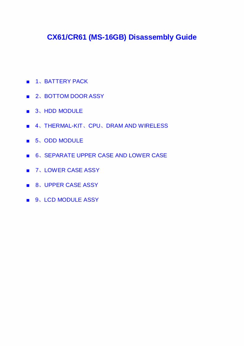
CX61/CR61 (MS-16GB) Disassembly Guide ■ 1、BATTERY PACK ■ 2、BOTTOM DOOR ASSY ■ 3、HDD MODULE ■ 4、THERMAL-KIT、CPU、DRAM AND WIRELESS ■ 5、ODD MODULE ■ 6、SEPARATE UPPER CASE AND LOWER CASE ■ 7、LOWER CASE ASSY ■ 8、UPPER CASE ASSY ■ 9、LCD MODULE ASSY
Transcript of MS-16GB Disassembly guide - forum-en.msi.com · cx61/cr61 (ms-16gb) disassembly guide 1、battery...
CX61/CR61 (MS-16GB) Disassembly Guide
■ 1、BATTERY PACK
■ 2、BOTTOM DOOR ASSY
■ 3、HDD MODULE
■ 4、THERMAL-KIT、CPU、DRAM AND WIRELESS
■ 5、ODD MODULE
■ 6、SEPARATE UPPER CASE AND LOWER CASE
■ 7、LOWER CASE ASSY
■ 8、UPPER CASE ASSY
■ 9、LCD MODULE ASSY
CX61/CR61 (MS-16GB)Disassembly Guide
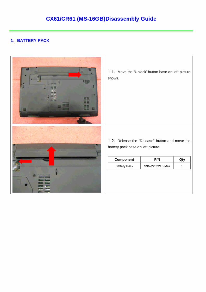
1、BATTERY PACK
1.1:Move the “Unlock’ button base on left picture
shows.
1.2:Release the “Release” button and move the
battery pack base on left picture.
Component P/N Qty
Battery Pack S9N-2262210-M47 1
CX61/CR61 (MS-16GB)Disassembly Guide
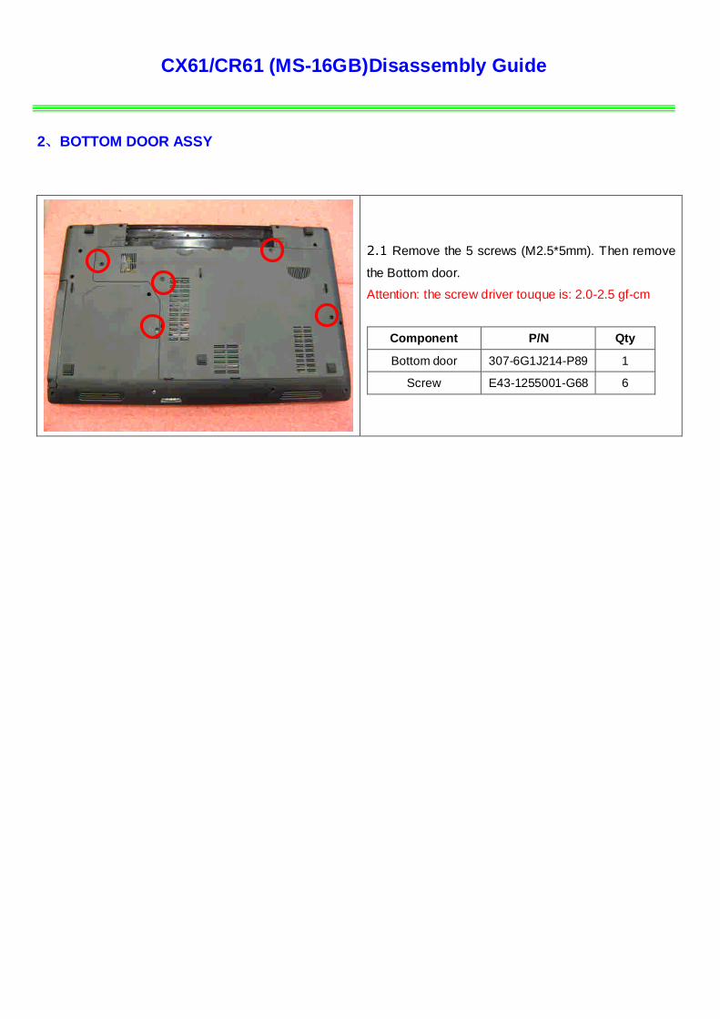
2、BOTTOM DOOR ASSY
2.1 Remove the 5 screws (M2.5*5mm). Then remove
the Bottom door.
Attention: the screw driver touque is: 2.0-2.5 gf-cm
Component P/N Qty
Bottom door 307-6G1J214-P89 1
Screw E43-1255001-G68 6
CX61/CR61 (MS-16GB)Disassembly Guide
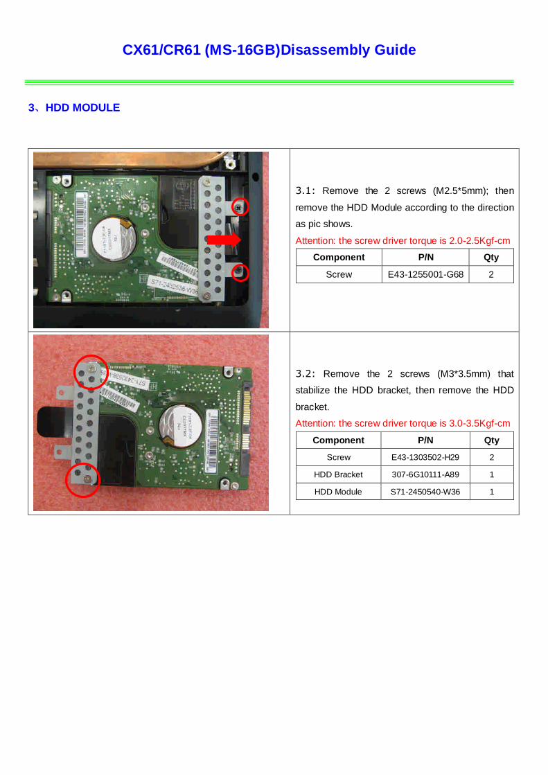
3、HDD MODULE
3.1: Remove the 2 screws (M2.5*5mm); then
remove the HDD Module according to the direction
as pic shows.
Attention: the screw driver torque is 2.0-2.5Kgf-cm
Component P/N Qty
Screw E43-1255001-G68 2
3.2: Remove the 2 screws (M3*3.5mm) that
stabilize the HDD bracket, then remove the HDD
bracket.
Attention: the screw driver torque is 3.0-3.5Kgf-cm
Component P/N Qty
Screw E43-1303502-H29 2
HDD Bracket 307-6G10111-A89 1
HDD Module S71-2450540-W36 1
CX61/CR61 (MS-16GB)Disassembly Guide
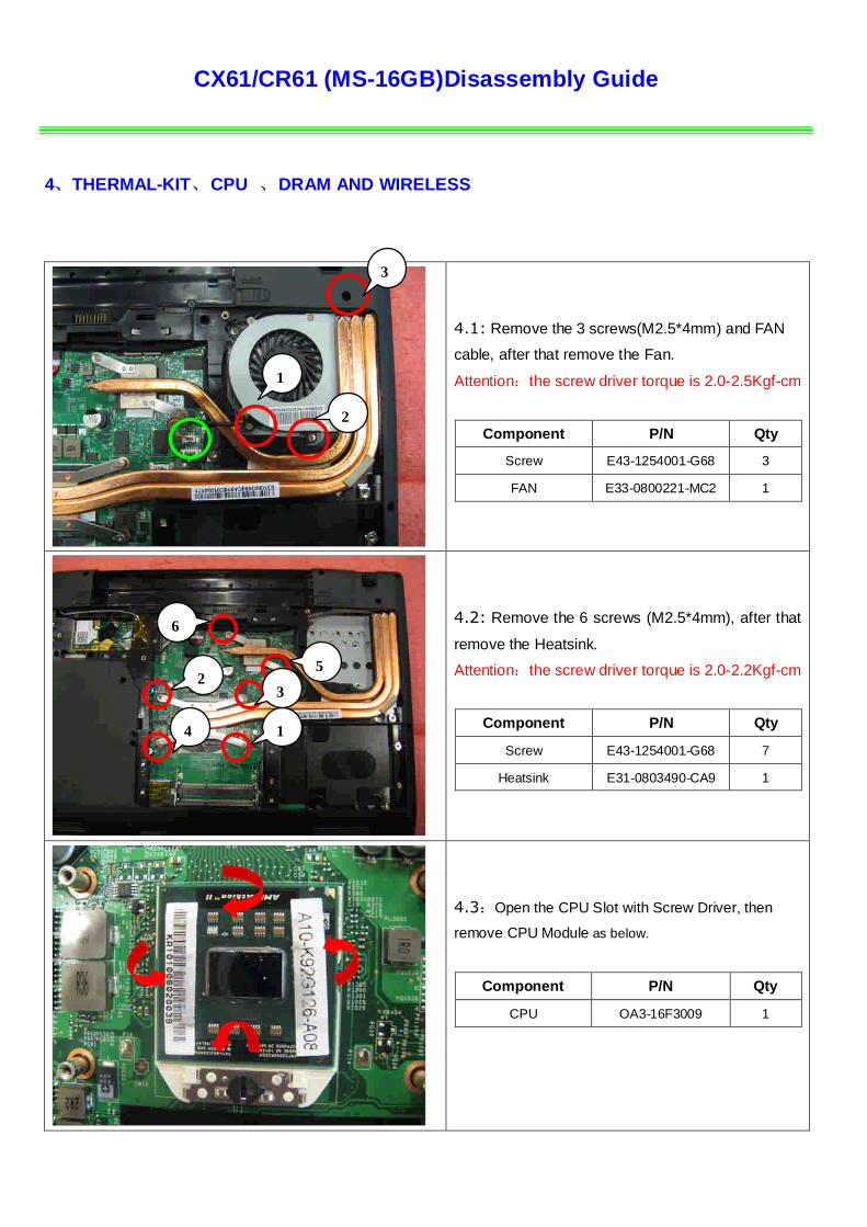
4、THERMAL-KIT、CPU 、DRAM AND WIRELESS
4.1: Remove the 3 screws(M2.5*4mm) and FAN
cable, after that remove the Fan.
Attention:the screw driver torque is 2.0-2.5Kgf-cm
Component P/N Qty
Screw E43-1254001-G68 3
FAN E33-0800221-MC2 1
4.2: Remove the 6 screws (M2.5*4mm), after that
remove the Heatsink.
Attention:the screw driver torque is 2.0-2.2Kgf-cm
Component P/N Qty
Screw E43-1254001-G68 7
Heatsink E31-0803490-CA9 1
4.3:Open the CPU Slot with Screw Driver, then
remove CPU Module as below.
Component P/N Qty
CPU OA3-16F3009 1
1
3
2
1
25
4
6
3
CX61/CR61 (MS-16GB)Disassembly Guide
4、THERMAL-KIT、CPU 、DRAM AND WIRELESS
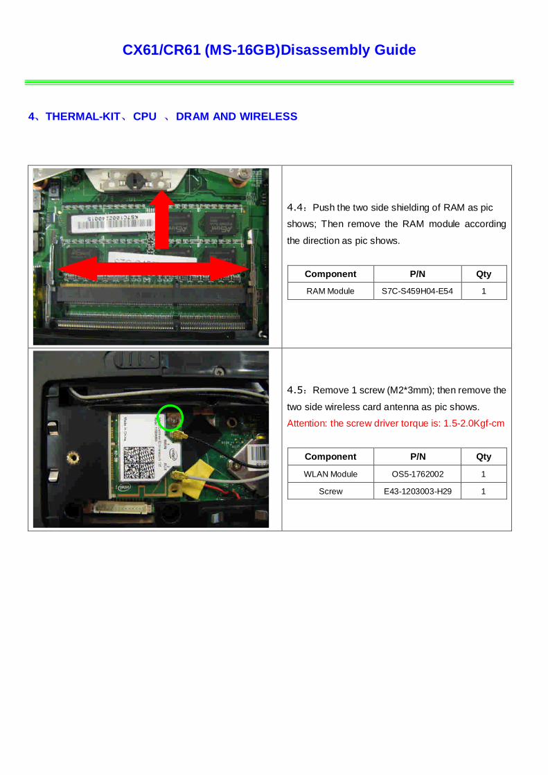
4.4:Push the two side shielding of RAM as pic
shows; Then remove the RAM module according
the direction as pic shows.
Component P/N Qty
RAM Module S7C-S459H04-E54 1
4.5:Remove 1 screw (M2*3mm); then remove the
two side wireless card antenna as pic shows.
Attention: the screw driver torque is: 1.5-2.0Kgf-cm
Component P/N Qty
WLAN Module OS5-1762002 1
Screw E43-1203003-H29 1
CX61/CR61 (MS-16GB)Disassembly Guide
5、ODD MODULE
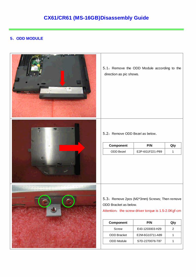
5.1:Remove the ODD Module according to the
direction as pic shows.
5.2:Remove ODD Bezel as below.
Component P/N Qty
ODD Bezel E2P-6G1F221-P89 1
5.3:Remove 2pcs (M2*3mm) Screws; Then remove
ODD Bracket as below.
Attention:the screw driver torque is 1.5-2.0Kgf-cm
Component P/N Qty
Screw E43-1203003-H29 2
ODD Bracket E2M-6G10711-A89 1
ODD Module S7D-2270076-T87 1
CX61/CR61 (MS-16GB)Disassembly Guide
6、SEPARATE UPPER CASE AND LOWER CASE
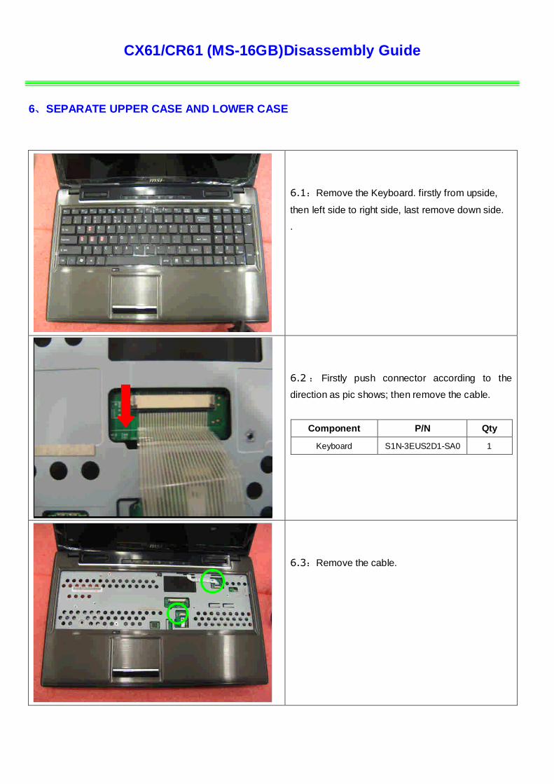
6.1:Remove the Keyboard. firstly from upside,
then left side to right side, last remove down side.
.
,
6.2 : Firstly push connector according to the
direction as pic shows; then remove the cable.
Component P/N Qty
Keyboard S1N-3EUS2D1-SA0 1
6.3:Remove the cable.

CX61/CR61 (MS-16GB)Disassembly Guide
6、SEPARATE UPPER CASE AND LOWER CASE
6.4:Remove 5 screws (M2*3.5mm).
Attention: the screw driver torque is 1.5-2.0Kgf-cm
Component P/N Qty
Screw E43-1203501-H29 5
6.5:Remove 2 screws (M2.5*5mm).
Attention: the screw driver torque is 2.0-2.5Kgf-cm
Component P/N Qty
Screw E43-1255001-G68 3
6.6:Remove the 15 screws (M2.5*5mm) .
Attention: the screw driver torque is 2.0-2.5Kgf-cm
Component P/N Qty
Screw E43-1255001-G68 15

CX61/CR61 (MS-16GB)Disassembly Guide
6、SEPARATE UPPER CASE AND LOWER CASE
6.7:Remove the LVDS, speaker and MIC cable.
6.8:Remove the power cable as pic shows.
6.9:Remove the 2 screws (M2.5*5mm). then
remove the upper case.
Attention: the screw driver torque is 2.0-2.5Kgf-cm
Component P/N Qty
Screw E43-1255001-G68 2

CX61/CR61 (MS-16GB)Disassembly Guide
7、LOWER CASE ASSY
7.1 Remove the 3screws (M2.5*4mm).then
remove the USB board.
Attention: the screw driver torque is 2.0-2.5Kgf-cm
Component P/N Qty
screw E43-1254001-H29 3
USB board 607-16GBB-A10 1
7.2 : Remove the 3 screws (M2.5*4mm).then
remove the main board.
Attention: the screw driver torque is 2.0-2.5Kgf-cm
Component P/N Qty
screw E43-1254001-H29 3
Main board 607-16GB1-A10 1
CX61/CR61 (MS-16GB)Disassembly Guide
7、LOWER CASE ASSY
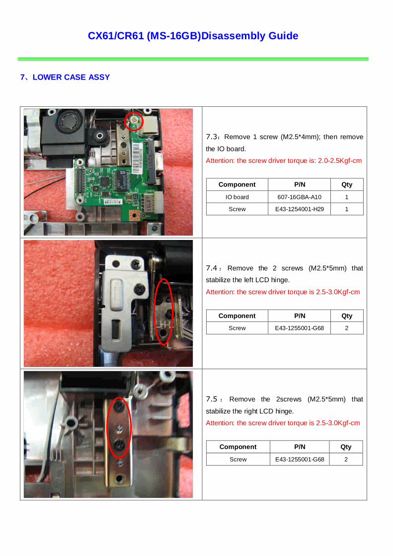
7.3:Remove 1 screw (M2.5*4mm); then remove
the IO board.
Attention: the screw driver torque is: 2.0-2.5Kgf-cm
Component P/N Qty
IO board 607-16GBA-A10 1
Screw E43-1254001-H29 1
7.4 : Remove the 2 screws (M2.5*5mm) that
stabilize the left LCD hinge.
Attention: the screw driver torque is 2.5-3.0Kgf-cm
Component P/N Qty
Screw E43-1255001-G68 2
7.5 : Remove the 2screws (M2.5*5mm) that
stabilize the right LCD hinge.
Attention: the screw driver torque is 2.5-3.0Kgf-cm
Component P/N Qty
Screw E43-1255001-G68 2
CX61/CR61 (MS-16GB)Disassembly Guide
7、LOWER CASE ASSY
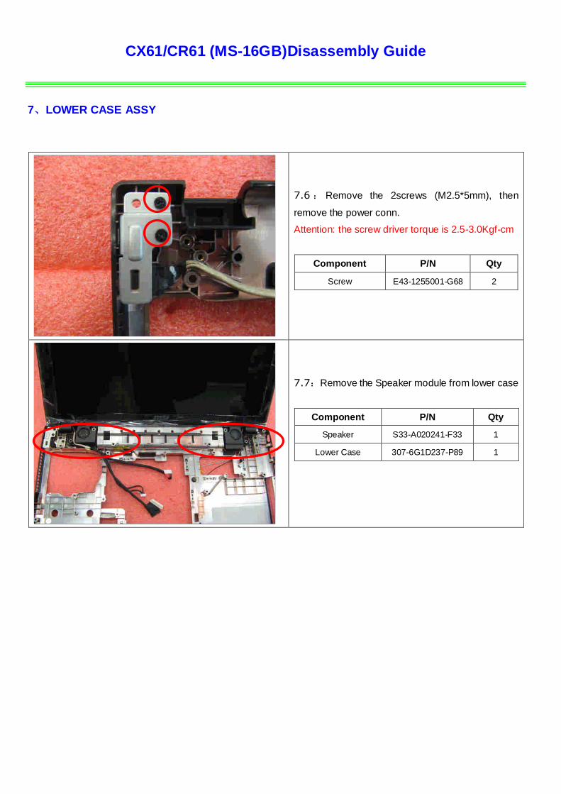
7.6 : Remove the 2screws (M2.5*5mm), then
remove the power conn.
Attention: the screw driver torque is 2.5-3.0Kgf-cm
Component P/N Qty
Screw E43-1255001-G68 2
7.7:Remove the Speaker module from lower case
Component P/N Qty
Speaker S33-A020241-F33 1
Lower Case 307-6G1D237-P89 1
CX61/CR61 (MS-16GB)Disassembly Guide
8、UPPER CASE ASSY
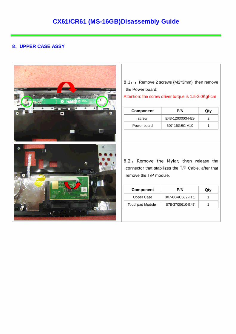
8.1::Remove 2 screws (M2*3mm), then remove
the Power board.
Attention: the screw driver torque is 1.5-2.0Kgf-cm
Component P/N Qty
screw E43-1203003-H29 2
Power board 607-16GBC-A10 1
8.2 : Remove the Mylar, then release the
connector that stabilizes the T/P Cable, after that
remove the T/P module.
Component P/N Qty
Upper Case 307-6G4C562-TF1 1
Touchpad Module S78-3700610-E47 1
CX61/CR61 (MS-16GB)Disassembly Guide
9、 LCD MODULE ASSY
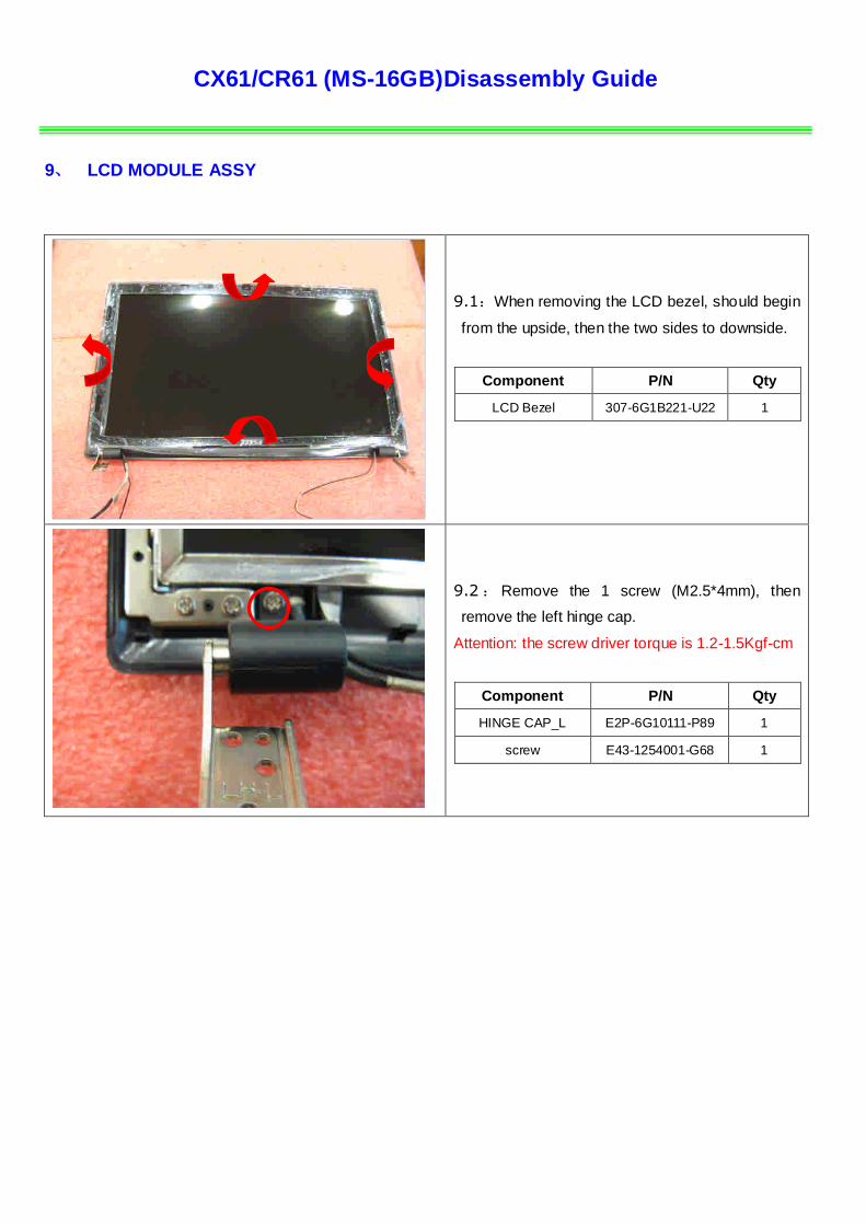
9.1:When removing the LCD bezel, should begin
from the upside, then the two sides to downside.
Component P/N Qty
LCD Bezel 307-6G1B221-U22 1
9.2 : Remove the 1 screw (M2.5*4mm), then
remove the left hinge cap.
Attention: the screw driver torque is 1.2-1.5Kgf-cm
Component P/N Qty
HINGE CAP_L E2P-6G10111-P89 1
screw E43-1254001-G68 1
CX61/CR61 (MS-16GB)Disassembly Guide
9、 LCD MODULE ASSY
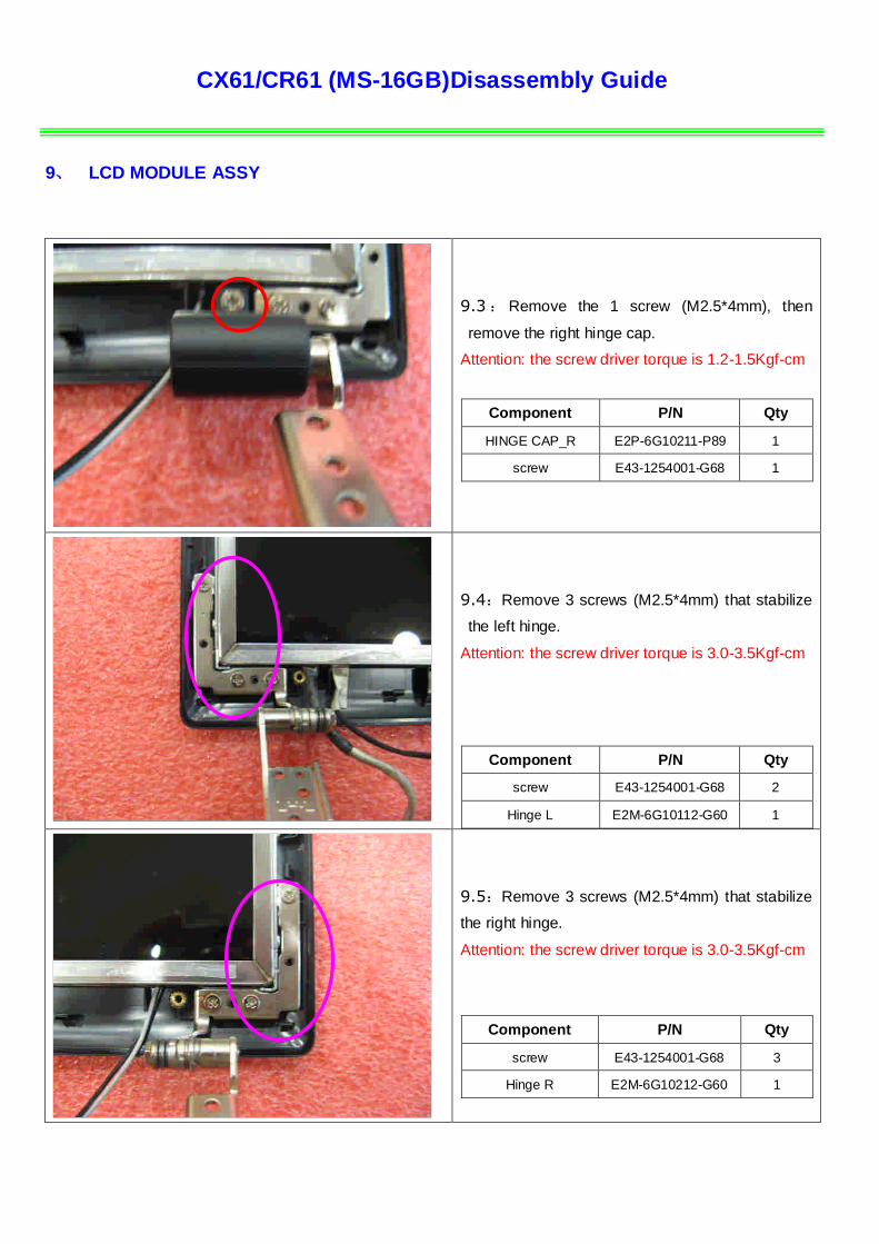
9.3 : Remove the 1 screw (M2.5*4mm), then
remove the right hinge cap.
Attention: the screw driver torque is 1.2-1.5Kgf-cm
Component P/N Qty
HINGE CAP_R E2P-6G10211-P89 1
screw E43-1254001-G68 1
9.4:Remove 3 screws (M2.5*4mm) that stabilize
the left hinge.
Attention: the screw driver torque is 3.0-3.5Kgf-cm
Component P/N Qty
screw E43-1254001-G68 2
Hinge L E2M-6G10112-G60 1
9.5:Remove 3 screws (M2.5*4mm) that stabilize
the right hinge.
Attention: the screw driver torque is 3.0-3.5Kgf-cm
Component P/N Qty
screw E43-1254001-G68 3
Hinge R E2M-6G10212-G60 1
CX61/CR61 (MS-16GB)Disassembly Guide
9、 LCD MODULE ASSY
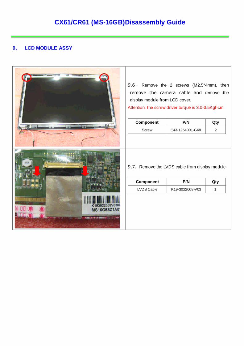
9.6 : Remove the 2 screws (M2.5*4mm), then
remove the camera cable and remove the
display module from LCD cover.
Attention: the screw driver torque is 3.0-3.5Kgf-cm
Component P/N Qty
Screw E43-1254001-G68 2
9.7:Remove the LVDS cable from display module
Component P/N Qty
LVDS Cable K19-3022008-V03 1
CX61/CR61 (MS-16GB)Disassembly Guide
9、 LCD MODULE ASSY
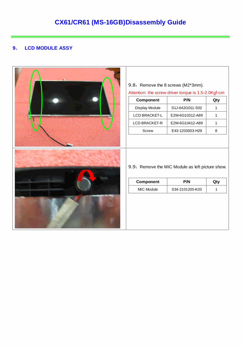
9.8:Remove the 8 screws (M2*3mm).
Attention: the screw driver torque is 1.5-2.0Kgf-cm
Component P/N Qty
Display Module S1J-642G011-S02 1
LCD BRACKET-L E2M-6G10312-A89 1
LCD BRACKET-R E2M-6G10412-A89 1
Screw E43-1203003-H29 8
9.9:Remove the MIC Module as left picture show.
Component P/N Qty
MIC Module S34-2101200-K03 1
CX61/CR61 (MS-16GB)Disassembly Guide
9、 LCD MODULE ASSY
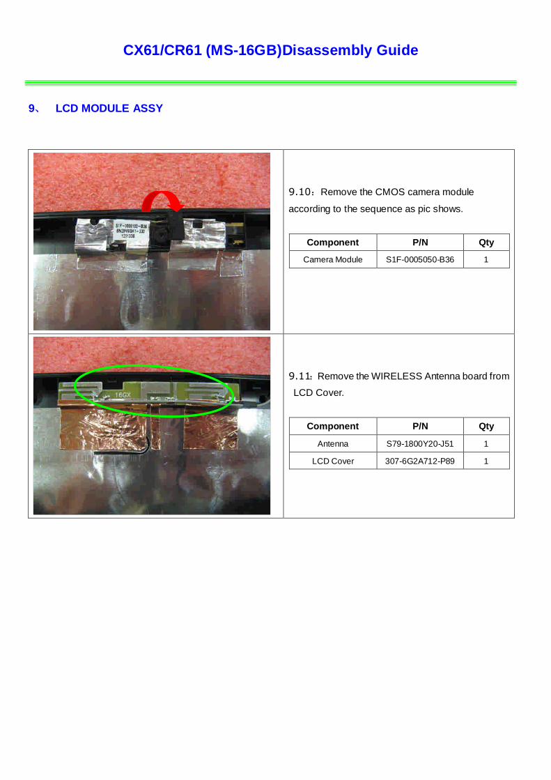
9.10:Remove the CMOS camera module
according to the sequence as pic shows.
Component P/N Qty
Camera Module S1F-0005050-B36 1
9.11:Remove the WIRELESS Antenna board from
LCD Cover.
Component P/N Qty
Antenna S79-1800Y20-J51 1
LCD Cover 307-6G2A712-P89 1
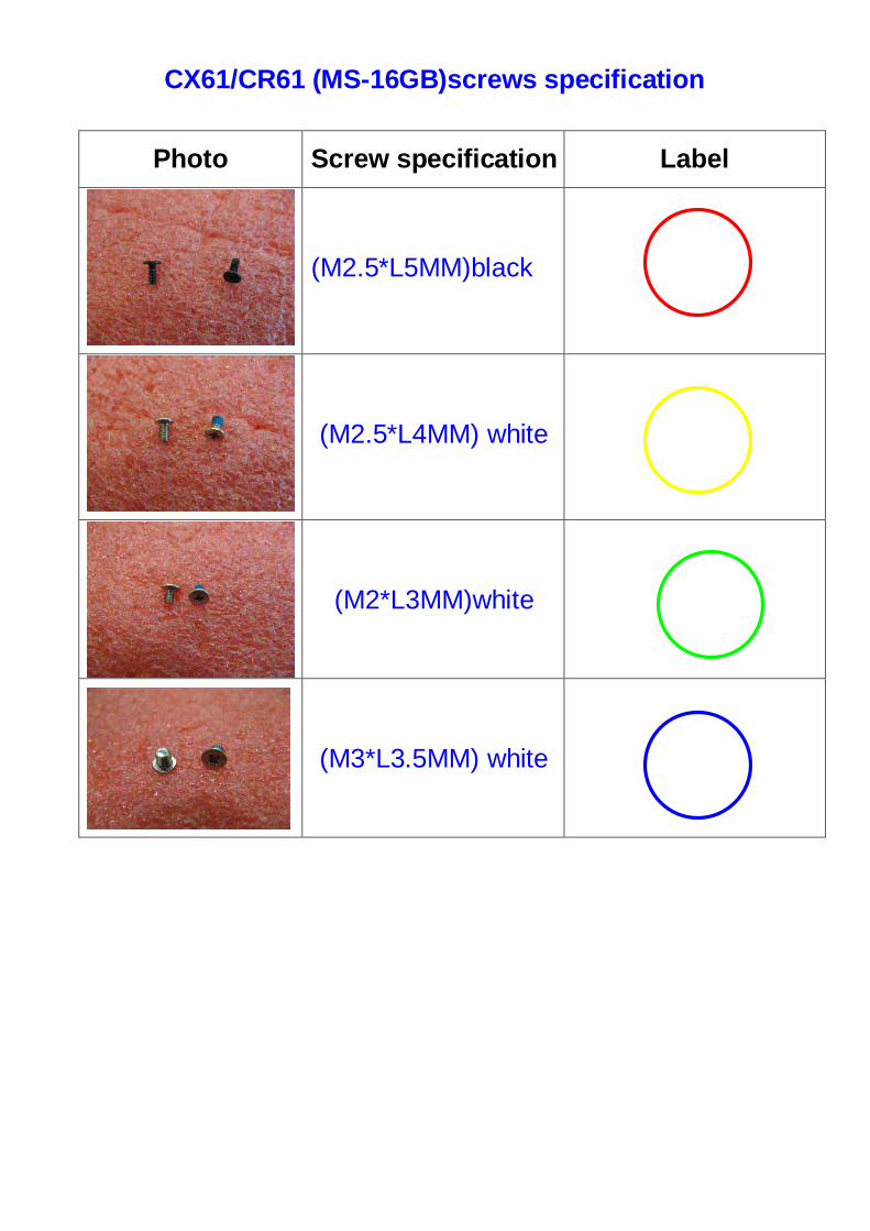
CX61/CR61 (MS-16GB)screws specification
Photo Screw specification Label
(M2.5*L5MM)black
(M2.5*L4MM) white
(M2*L3MM)white
(M3*L3.5MM) white
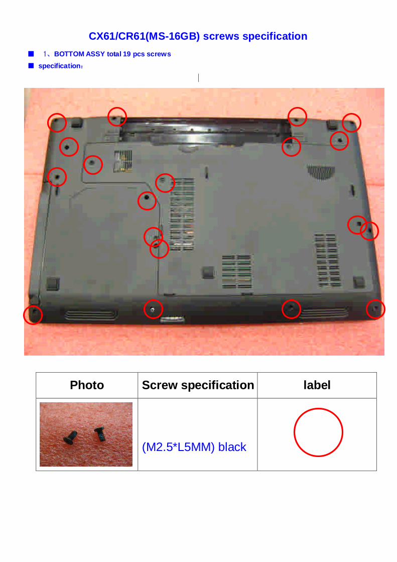
CX61/CR61(MS-16GB) screws specification
■ 1、BOTTOM ASSY total 19 pcs screws
■ specification:
Photo Screw specification label
(M2.5*L5MM) black
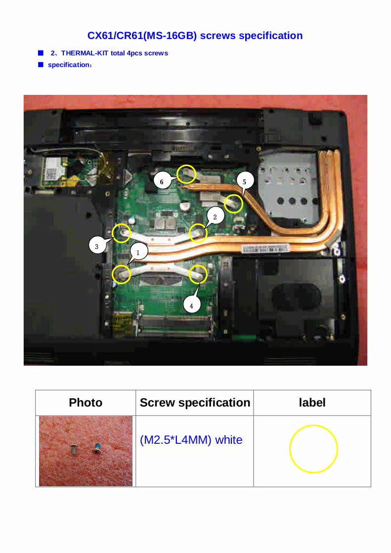
CX61/CR61(MS-16GB) screws specification
■ 2、THERMAL-KIT total 4pcs screws
■ specification:
Photo Screw specification label
(M2.5*L4MM) white
3
4
2
1
56

CX61/CR61(MS-16GB) screws specification
■ 3、WIRELESS CARD and HDD ASSY total 3pcs screws
■ specification:
Photo Screw specification label
(M3*L3.5MM) white
(M2*L3MM)white
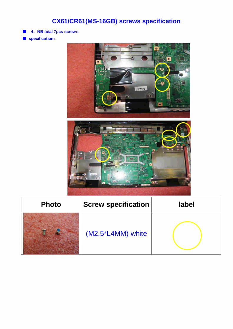
CX61/CR61(MS-16GB) screws specification
■ 4、NB total 7pcs screws
■ specification:
Photo Screw specification label
(M2.5*L4MM) white
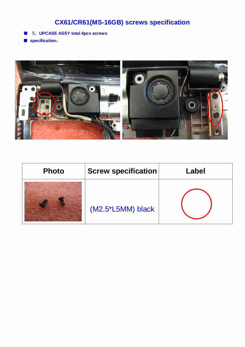
CX61/CR61(MS-16GB) screws specification
■ 5、UPCASE ASSY total 4pcs screws
■ specification:
Photo Screw specification Label
(M2.5*L5MM) black
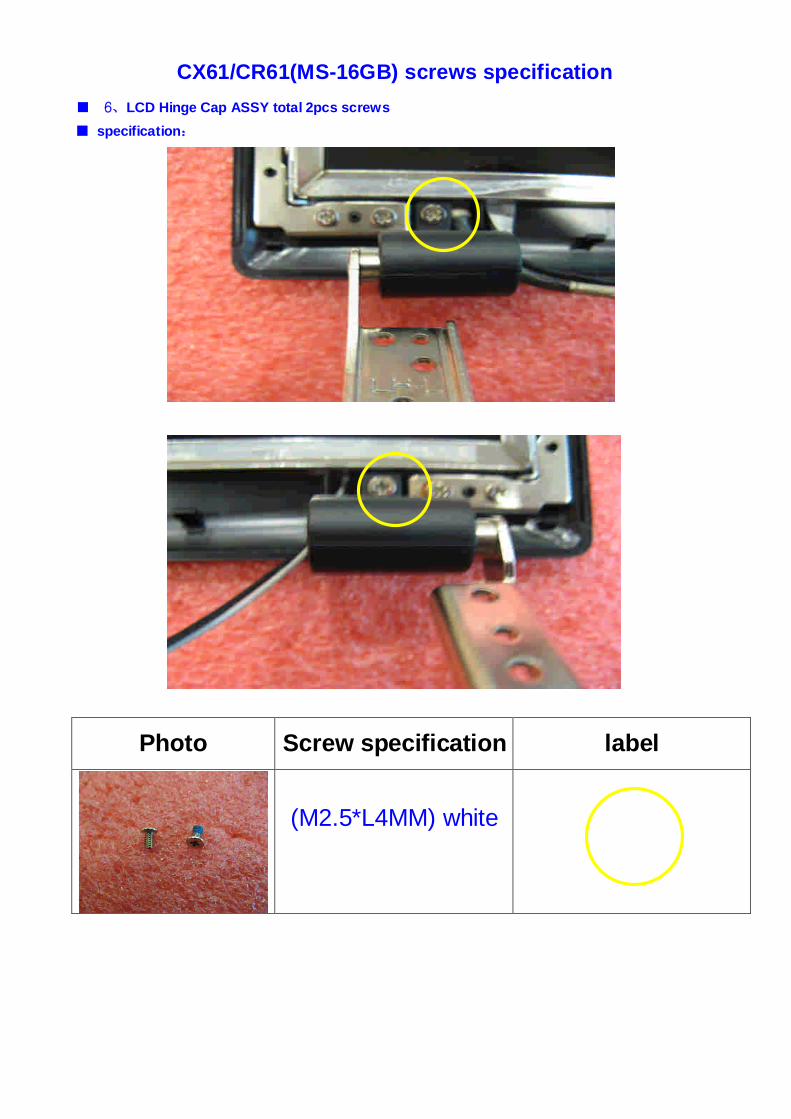
CX61/CR61(MS-16GB) screws specification
■ 6、LCD Hinge Cap ASSY total 2pcs screws
■ specification:
Photo Screw specification label
(M2.5*L4MM) white
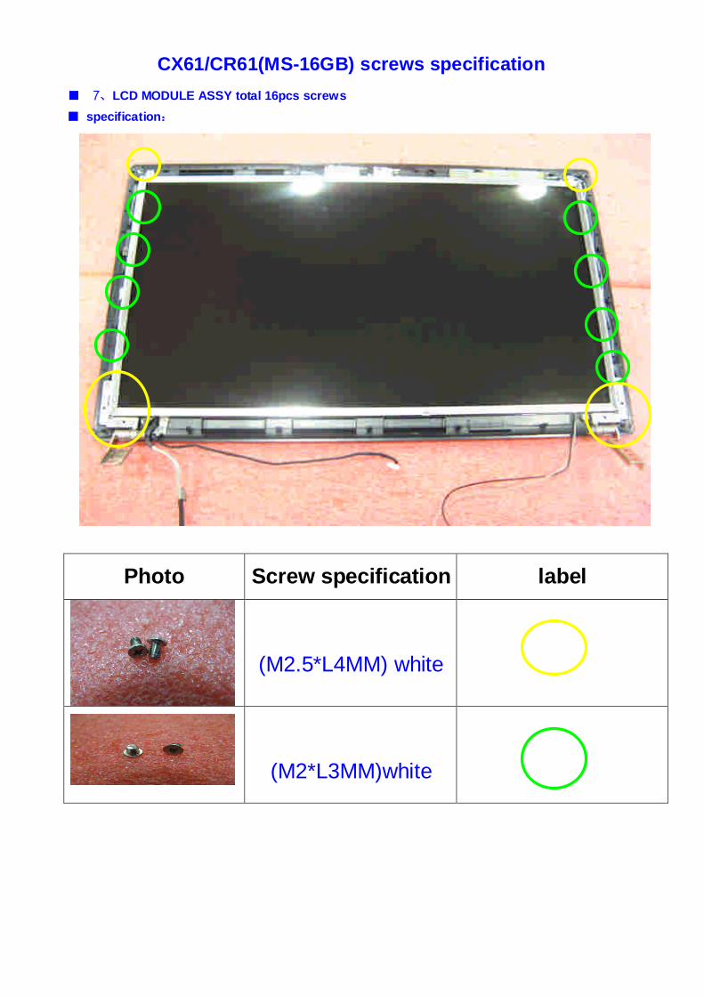
CX61/CR61(MS-16GB) screws specification
■ 7、LCD MODULE ASSY total 16pcs screws
■ specification:
Photo Screw specification label
(M2.5*L4MM) white
(M2*L3MM)white